EP4425673A1 - Power battery pack and electric device - Google Patents
Power battery pack and electric device Download PDFInfo
- Publication number
- EP4425673A1 EP4425673A1 EP23892762.8A EP23892762A EP4425673A1 EP 4425673 A1 EP4425673 A1 EP 4425673A1 EP 23892762 A EP23892762 A EP 23892762A EP 4425673 A1 EP4425673 A1 EP 4425673A1
- Authority
- EP
- European Patent Office
- Prior art keywords
- pressure relief
- groove
- plate
- battery pack
- power battery
- Prior art date
- Legal status (The legal status is an assumption and is not a legal conclusion. Google has not performed a legal analysis and makes no representation as to the accuracy of the status listed.)
- Pending
Links
Images



Classifications
-
- H—ELECTRICITY
- H01—ELECTRIC ELEMENTS
- H01M—PROCESSES OR MEANS, e.g. BATTERIES, FOR THE DIRECT CONVERSION OF CHEMICAL ENERGY INTO ELECTRICAL ENERGY
- H01M50/00—Constructional details or processes of manufacture of the non-active parts of electrochemical cells other than fuel cells, e.g. hybrid cells
- H01M50/30—Arrangements for facilitating escape of gases
- H01M50/35—Gas exhaust passages comprising elongated, tortuous or labyrinth-shaped exhaust passages
- H01M50/367—Internal gas exhaust passages forming part of the battery cover or case; Double cover vent systems
-
- H—ELECTRICITY
- H01—ELECTRIC ELEMENTS
- H01M—PROCESSES OR MEANS, e.g. BATTERIES, FOR THE DIRECT CONVERSION OF CHEMICAL ENERGY INTO ELECTRICAL ENERGY
- H01M10/00—Secondary cells; Manufacture thereof
- H01M10/60—Heating or cooling; Temperature control
- H01M10/61—Types of temperature control
- H01M10/613—Cooling or keeping cold
-
- H—ELECTRICITY
- H01—ELECTRIC ELEMENTS
- H01M—PROCESSES OR MEANS, e.g. BATTERIES, FOR THE DIRECT CONVERSION OF CHEMICAL ENERGY INTO ELECTRICAL ENERGY
- H01M10/00—Secondary cells; Manufacture thereof
- H01M10/60—Heating or cooling; Temperature control
- H01M10/65—Means for temperature control structurally associated with the cells
- H01M10/655—Solid structures for heat exchange or heat conduction
- H01M10/6554—Rods or plates
-
- H—ELECTRICITY
- H01—ELECTRIC ELEMENTS
- H01M—PROCESSES OR MEANS, e.g. BATTERIES, FOR THE DIRECT CONVERSION OF CHEMICAL ENERGY INTO ELECTRICAL ENERGY
- H01M10/00—Secondary cells; Manufacture thereof
- H01M10/60—Heating or cooling; Temperature control
- H01M10/65—Means for temperature control structurally associated with the cells
- H01M10/655—Solid structures for heat exchange or heat conduction
- H01M10/6556—Solid parts with flow channel passages or pipes for heat exchange
-
- H—ELECTRICITY
- H01—ELECTRIC ELEMENTS
- H01M—PROCESSES OR MEANS, e.g. BATTERIES, FOR THE DIRECT CONVERSION OF CHEMICAL ENERGY INTO ELECTRICAL ENERGY
- H01M10/00—Secondary cells; Manufacture thereof
- H01M10/60—Heating or cooling; Temperature control
- H01M10/65—Means for temperature control structurally associated with the cells
- H01M10/658—Means for temperature control structurally associated with the cells by thermal insulation or shielding
-
- H—ELECTRICITY
- H01—ELECTRIC ELEMENTS
- H01M—PROCESSES OR MEANS, e.g. BATTERIES, FOR THE DIRECT CONVERSION OF CHEMICAL ENERGY INTO ELECTRICAL ENERGY
- H01M50/00—Constructional details or processes of manufacture of the non-active parts of electrochemical cells other than fuel cells, e.g. hybrid cells
- H01M50/20—Mountings; Secondary casings or frames; Racks, modules or packs; Suspension devices; Shock absorbers; Transport or carrying devices; Holders
- H01M50/204—Racks, modules or packs for multiple batteries or multiple cells
-
- H—ELECTRICITY
- H01—ELECTRIC ELEMENTS
- H01M—PROCESSES OR MEANS, e.g. BATTERIES, FOR THE DIRECT CONVERSION OF CHEMICAL ENERGY INTO ELECTRICAL ENERGY
- H01M50/00—Constructional details or processes of manufacture of the non-active parts of electrochemical cells other than fuel cells, e.g. hybrid cells
- H01M50/20—Mountings; Secondary casings or frames; Racks, modules or packs; Suspension devices; Shock absorbers; Transport or carrying devices; Holders
- H01M50/289—Mountings; Secondary casings or frames; Racks, modules or packs; Suspension devices; Shock absorbers; Transport or carrying devices; Holders characterised by spacing elements or positioning means within frames, racks or packs
-
- H—ELECTRICITY
- H01—ELECTRIC ELEMENTS
- H01M—PROCESSES OR MEANS, e.g. BATTERIES, FOR THE DIRECT CONVERSION OF CHEMICAL ENERGY INTO ELECTRICAL ENERGY
- H01M50/00—Constructional details or processes of manufacture of the non-active parts of electrochemical cells other than fuel cells, e.g. hybrid cells
- H01M50/30—Arrangements for facilitating escape of gases
- H01M50/35—Gas exhaust passages comprising elongated, tortuous or labyrinth-shaped exhaust passages
-
- H—ELECTRICITY
- H01—ELECTRIC ELEMENTS
- H01M—PROCESSES OR MEANS, e.g. BATTERIES, FOR THE DIRECT CONVERSION OF CHEMICAL ENERGY INTO ELECTRICAL ENERGY
- H01M50/00—Constructional details or processes of manufacture of the non-active parts of electrochemical cells other than fuel cells, e.g. hybrid cells
- H01M50/30—Arrangements for facilitating escape of gases
- H01M50/342—Non-re-sealable arrangements
- H01M50/3425—Non-re-sealable arrangements in the form of rupturable membranes or weakened parts, e.g. pierced with the aid of a sharp member
-
- Y—GENERAL TAGGING OF NEW TECHNOLOGICAL DEVELOPMENTS; GENERAL TAGGING OF CROSS-SECTIONAL TECHNOLOGIES SPANNING OVER SEVERAL SECTIONS OF THE IPC; TECHNICAL SUBJECTS COVERED BY FORMER USPC CROSS-REFERENCE ART COLLECTIONS [XRACs] AND DIGESTS
- Y02—TECHNOLOGIES OR APPLICATIONS FOR MITIGATION OR ADAPTATION AGAINST CLIMATE CHANGE
- Y02E—REDUCTION OF GREENHOUSE GAS [GHG] EMISSIONS, RELATED TO ENERGY GENERATION, TRANSMISSION OR DISTRIBUTION
- Y02E60/00—Enabling technologies; Technologies with a potential or indirect contribution to GHG emissions mitigation
- Y02E60/10—Energy storage using batteries
Definitions
- the present application relates to the technical field of power batteries, in particular to a power battery pack and an electrical apparatus.
- a battery is an apparatus which can convert chemical energy into electrical energy
- a battery pack is a component unit of the battery, and a plurality of battery cells are arranged in the battery pack.
- pressure of the battery pack can only be relieved by means of the pressure relief valve of the whole pack, or the battery pack is isolated into one pressure relief cavity for pressure relief, overall pressure relief of the battery pack may increase probability of heat spread to battery cells in neighboring modules, and overall thermal runaway is easily caused.
- the technical problem to be solved by the present application is to overcome the defect in the prior art that overall pressure relief of a battery pack increases probability of heat spread of battery cells in neighboring modules, and therefore, the present application provides a power battery pack which reduces heat spread of battery cells in neighboring modules.
- a power battery pack comprising a supporting plate and a module.
- the supporting plate is provided with a pressure relief groove, the pressure relief groove has a plurality of pressure relief cavities arranged in sequence along a length direction thereof, and each pressure relief cavity is provided with at least one pressure relief hole in each side wall on each of two opposite sides of the pressure relief groove.
- the module comprises a plurality of battery cells arranged in sequence, each cell corresponds to a pressure relief cavity, and each cell is provided with an explosion-proof valve which is partially positioned in the pressure relief cavity.
- a thermal insulation pad is arranged between every two neighboring battery cells, the thermal insulation pad extends into the pressure relief groove and abuts against an inner wall of the pressure relief groove, so that every two neighboring thermal insulation pads partition one pressure relief cavity in the pressure relief groove.
- the supporting plate has a structure of a plate body, a part of the plate body of the supporting plate is inwardly recessed to form the pressure relief groove, and the module is attached to another part, which protrudes relative to the pressure relief groove, of the plate body of the supporting plate.
- an area of a cross section of the pressure relief hole gradually decreases in a direction from the inner wall to the outer wall of the pressure relief groove, and the cross section of the pressure relief hole is a section perpendicular to a central axis of the pressure relief hole.
- a one-way membrane structure or a one-way valve is arranged at the pressure relief hole.
- the power battery pack further comprises a first cooling plate, wherein the first cooling plate is provided with an avoidance groove, a baffle is provided at one end of the avoidance groove, the pressure relief groove penetrates through the avoidance groove, the baffle shields one end of the pressure relief groove, the pressure relief hole is arranged to avoid the avoidance groove, and the first cooling plate is connected to the supporting plate.
- the first cooling plate comprises: a runner plate, provided with a first groove; and a cooling flat plate, provided with a second groove, wherein the cooling flat plate is buckled on the runner plate, so that the second groove is positioned opposite to the first groove to form the avoidance groove.
- the power battery pack further comprises a second cooling plate, wherein the second cooling plate and the first cooling plate are oppositely arranged on two opposite sides of the module.
- the power battery pack further comprises a bottom protective plate, wherein the bottom protective plate abuts against an outer wall of a groove bottom of the pressure relief groove, so that a pressure relief channel is formed along each of two opposite sides, in a width direction, of the pressure relief groove.
- the present application further provides an electrical apparatus, comprising a power battery pack, wherein the power battery pack is configured as the power battery pack according to any one of the above.
- Power battery pack 110. Supporting plate; 111. Pressure relief groove; 113. Pressure relief hole; 115. Pressure relief channel; 117. Pressure relief cavity; 120. Module; 121. Battery cell; 123. Thermal insulation pad; 125. Explosion-proof valve; 127. Module end plate; 130. Bottom protective plate; 140. Box body; 141. Transverse partition plate; 143. Longitudinal partition plate; 1401. Side clearance; 150. Spacer; 160. Module pressure relief valve; 170. Electrical assembly; 180. Box pressure relief valve; 191. First cooling plate; 1911. Runner plate; 1913. Cooling flat plate; 193. Second cooling plate; Avoidance groove, 1901; Baffle, 1903.
- a power battery pack 100 includes a supporting plate 110 and a module 120.
- the supporting plate 110 is provided with a pressure relief groove 111
- the pressure relief groove 111 has a plurality of pressure relief cavities 117 arranged in sequence along a length direction thereof, and each pressure relief cavity 117 is provided with at least one pressure relief hole 113 in each side wall on each of two opposite sides of the pressure relief groove 111.
- the module 120 includes a plurality of battery cells 121 arranged in sequence, each battery cell 121 corresponds to a pressure relief cavity 117, and each battery cell 121 is provided with an explosion-proof valve 125 which is partially positioned in the pressure relief cavity 117.
- the supporting plate 110 has a uniform thickness.
- the pressure relief groove 111 extends from a first side of the supporting plate 110 to an opposite second side, wherein the first side is opposite to the second side.
- the pressure relief groove 111 has a groove bottom and two opposite side walls, and the pressure relief hole 113 is formed in the side wall and close to the groove bottom.
- the plurality of pressure relief holes 113 are formed in sequence along a length direction of the pressure relief groove 111.
- the module 120 includes the plurality of battery cells 121, and the explosion-proof valve 125 is arranged at a bottom of each battery cell 121.
- the plurality of battery cells 121 are arranged along the length direction of the pressure relief groove 111, and the explosion-proof valve 125 of each battery cell 121 is opposite to the pressure relief groove 111.
- the module 120 and the pressure relief cavity 117 formed by the pressure relief groove 111 can accommodate part of the explosion-proof valve 125, and an opening position of the pressure relief hole 113 is away from the explosion-proof valve 125.
- a thermal insulation pad 123 is arranged between every two neighboring battery cells 121, the thermal insulation pad 123 extends into the pressure relief groove 111 and abuts against an inner wall of the pressure relief groove 111, so that every two neighboring thermal insulation pads 123 partition one sealed pressure relief cavity 117 in the pressure relief groove 111.
- the bottom of the thermal insulation pad 123 protrudes to form a protruding structure, and the protruding structure of the thermal insulation pad 123 is attached to the side walls and the bottom wall on two sides of the pressure relief groove 111, so as to form an independent pressure relief cavity 117 for a single battery cell.
- pressure relief holes 113 are also present in the pressure relief cavities 117 corresponding to the neighboring battery cells 121, as the pressure relief cavities 117 corresponding to the neighboring battery cells 121 are sealed, it is difficult for the high-temperature gas to enter, and the high-temperature gas is discharged along the pressure relief channels 115 on both sides.
- the supporting plate 110 has a structure of a plate body, a part of the plate body of the supporting plate 110 is inwardly recessed to form the pressure relief groove 111, and the module 120 is attached to another part, which protrudes relative to the pressure relief groove 111, of the plate body of the supporting plate 110.
- the pressure relief groove 111 may be formed by the supporting plate 110 being recessed toward one side of the plate surface, and two opposite sides of the pressure relief groove 111 are protruded relative to the pressure relief groove 111.
- the protruded parts have flat surfaces and may be used for bonding with the battery cells 121 of the module 120.
- an area of a cross section of the pressure relief hole 113 gradually decreases in a direction from the inner wall to an outer wall of the pressure relief groove 111, and the cross section of the pressure relief hole 113 is a section perpendicular to a central axis of the pressure relief hole 113.
- the area of the cross section of the pressure relief hole 113 gradually decreases from the inner side wall to the outer part of the pressure relief groove 111, so that the pressure relief hole 113 has a structure of a bell. Specifically, the area of the cross section of the pressure relief hole 113 close to the inner side wall of the pressure relief groove 111 is greater than that far from the inner side wall of the pressure relief groove 111.
- the cross section of the pressure relief hole 113 is a plane perpendicular to the central axis of the pressure relief hole 113.
- the pressure relief hole 113 may be a strip-shaped hole, and the bell-mouth shape of the pressure relief hole 113 will increase difficulty for the hot gas to enter the pressure relief cavity 117 corresponding to the pressure relief hole 113 from the outside, so that, when thermal runaway occurs to a single battery cell 121, the hot gas is not discharged to the neighboring battery cell 121.
- a one-way membrane structure or a one-way valve is arranged at the pressure relief hole 113.
- the one-way membrane structure is made of mica, and the gas in the pressure relief cavity 117 can break through the one-way membrane structure and be discharged to the outside, but cannot return to the pressure relief cavity.
- the one-way membrane structure can also be replaced by the one-way valve, so that the gas can only be discharged to the outside from the pressure relief cavity 117 through the one-way membrane structure, and not discharged to the pressure relief cavity 117 through the one-way membrane structure. Therefore, the difficulty for the hot gas to enter the pressure relief cavity 117 corresponding to the pressure relief hole 113 from the outside can also be increased.
- the power battery pack further includes a first cooling plate 191, the first cooling plate 191 is provided with an avoidance groove 1901, a baffle 1903 is arranged at one end of the avoidance groove 1901, the pressure relief groove 111 penetrates through the avoidance groove 1901, the baffle 1903 shields one end of the pressure relief groove 111, the pressure relief hole 113 is arranged to avoid the avoidance groove 1901, and the first cooling plate 191 is connected to the supporting plate 110.
- the first cooling plate 191 may be a water cooling plate, and the first cooling plate 191 may be adhered to the supporting plate 110 by means of a heat-conducting structure to cool the battery cell 121.
- the avoidance grooves 1901 in the first cooling plate 191 correspond to the pressure relief grooves 111 one by one, and the first cooling plate 191 can be connected to the supporting plate 110 in an adhesive manner.
- the avoidance groove 1901 is sleeved outside the pressure relief groove 111, and the pressure relief hole 113 is arranged to avoid the side wall of the avoidance groove 1901, so that the gas can be discharged from the pressure relief hole 113.
- the baffle 1903 is arranged at one end of the avoidance groove 1901, the baffle 1903 can block one end of the pressure relief groove 111, and the other end of the pressure relief groove 111 can abut against the side wall of a box body 140, and therefore, the pressure relief groove 111 can form a sealing groove.
- the module 120 can be cooled by the first cooling plate 191, and quality of the power battery pack 100 can be improved.
- the first cooling plate 191 may be flanged by a seal to prevent other impurities from being discharged into space between the supporting plate 110 and the bottom protective plate 130.
- a module pressure relief valve 160 and a box pressure relief valve 180 may be arranged on a side wall of the box body 140.
- the first cooling plate 191 includes: a runner plate 1911 and a cooling flat plate 1913, wherein the runner plate 1911 is provided with a first groove; and the cooling flat plate 1913 is provided with a second groove, the cooling flat plate 1913 is buckled on the runner plate 1911, so that the second groove is positioned opposite to the first groove to form the avoidance groove 1901.
- the cooling flat plate 1913 can be used to support the supporting plate 110.
- the runner plate 1911 and the cooling flat plate 1913 can be made of aluminum, and the supporting plate 110 can be made of a steel plate.
- the power battery pack further includes a second cooling plate 193, the second cooling plate 193 and the first cooling plate 191 are oppositely arranged on two opposite sides of the module 120.
- the second cooling plate 193 may be a water cooling plate or a flat plate.
- the second cooling plate 193 is bonded to the module 120, and the second cooling plate 193 and the first cooling plate 191 are arranged oppositely, so as to form dual cooling on the module 120, and achieve a better cooling effect.
- the power battery pack further includes a bottom protective plate 130, the supporting plate 110 is arranged on the bottom protective plate 130, and a pressure relief channel 115 is formed between the bottom protective plate 130 and the supporting plate 110.
- the bottom protective plate 130 and the supporting plate 110 are respectively have a structure of a plate, the plate surface of the bottom protective plate 130 can be a plane, and the outer surface of the bottom wall of the pressure relief groove 111 also has a plane, so that the bottom wall of the pressure relief groove 111 is conveniently bonded with the bottom protective plate 130.
- the outer surface of the groove bottom of the pressure relief groove 111 of the supporting plate 110 is attached to the bottom protective plate 130, and parts of the supporting plate 110 located at the two opposite sides of the pressure relief groove 111 respectively protrude in a direction away from the bottom protective plate 130, so as to form the pressure relief channel 115 between the supporting plate 110 and the bottom protective plate 130.
- the pressure relief hole 113 has a shape of a bell mouth, so that the hot gas entering the pressure relief channel 115 is prevented or reduced from entering other pressure relief cavities 117 and the hot gas can be discharged along the pressure relief channels 115 on two sides.
- the pressure relief channel 115 is arranged on at least one side of the two opposite sides of the pressure relief groove 111, and the pressure relief channel 115 extends from the first side to the second side of the supporting plate 110, the protruding part of the supporting plate 110 relative to the pressure relief groove 111 is arranged away from the bottom protective plate 130, and a bottom clearance is formed with the bottom protective plate 130 and bottom clearances on the two opposite sides of the pressure relief groove 111 form the pressure relief channel 115.
- the protruding part of the supporting plate 110 relative to the pressure relief groove 111 has a convex plane abutting against the battery cell 121, which enables the module 120 to be supported on the supporting plate 110.
- the groove bottom of the groove can also be a plane, which is beneficial for the supporting plate 110 to be supported on the bottom protective plate 130.
- the bottom protective plate 130 can protect the module 120, and the one-way membrane structure or the one-way valve can isolate the explosion-proof valve 125 from external space, and in this way, the hot gas can be directly discharged to the atmosphere outside the pressure relief cavity 117 if thermal runaway occurs to a single battery cell 121.
- the power battery pack further includes a box body 140, a transverse partition plate 141 is arranged in the box body 140, the transverse partition plate 141 separates an accommodating cavity and a side clearance 1401 in the box body 140, the module 120 is arranged in the accommodating cavity, and an electrical assembly 170 is arranged in the side clearance 1401.
- the box body 140 has a cubic structure, the transverse partition plate 141 and a longitudinal partition plate 143 are arranged in the box body 140, the longitudinal partition plate 143 separates two areas in the accommodating cavity, and each area is provided with a module 120.
- the power battery pack further includes a spacer 150 and a module pressure relief valve 160
- the spacer 150 is arranged in the side clearance 1401, the spacer 150 is buckled with the pressure relief groove 111, an end surface of one end of the spacer 150 abuts against the transverse partition plate 141, and an end surface of the other opposite end of the spacer 150 abuts against the inner wall of the box body 140
- the module pressure relief valve 160 is arranged on the box body 140, and the module pressure relief valve 160 is arranged corresponding to the pressure relief groove 111, and the electrical assembly 170 abuts against the spacer 150.
- the spacer 150 is used to extend the pressure relief groove 111 corresponding to the battery cell 121 in the side clearance 1401.
- the module pressure relief valve 160 corresponding to the pressure relief groove 111 is arranged on the box body 140, the module pressure relief valve 160 can relieve pressure of the gas entering the pressure relief groove 111.
- the power battery pack further includes a box pressure relief valve 180, the box pressure relief valve 180 is arranged on the box body 140, and the box pressure relief valve 180 is adapted to relieve pressure of the box body 140.
- the box pressure relief valve 180 can relieve pressure of flue gas discharged from a clearance of the independent channel.
- the battery pack mainly includes the bottom protective plate 130, the supporting plate 110, the module 120, the box body 140, the spacer 150, the electrical assembly 170, a high and low voltage connector, the pressure relief valve, the first cooling plate 191, and the second cooling plate 193.
- the box body 140 is provided with a cross beam 141 and a longitudinal beam 143 in the middle.
- a basic installation process is inverted installation: after the box body 140 is pre-installed with the pressure relief valve, the water cooling pipe connector and other parts, the second cooling plate 193 is installed first, a heat-conducting structural adhesive is applied to a sub-channel position of the second cooling plate 193, the assembled module 120 is lifted into the box for laminating and curing; then, electrical parts and the water cooling pipeline in the box body 140 are installed, the structural adhesive is applied to a corresponding position of a contact surface between the bottom of the battery cell 121 and the supporting plate 110, a bottom assembly in which the supporting plate 110 is welded to the bottom protective plate 130 is then installed, bolt fastening/FDS fastening is performed, and laminating and curing are performed.
- the single supporting plate 110 can also be first bonded to the bottom of the module 120, and after curing as a whole, the whole is lifted into the box for bonding and curing through lifting holes in a lifting plate, and then the first cooling plate 191 is installed after the structural adhesive is applied to the contact surface between the supporting plate 110 and the bottom protective plate 130, and finally the bottom protective plate 130 is installed.
- This mode is a full bonding mode.
- the spacer 150 may be separately installed at the end, or may be integrated onto the box body 140. After installation, an independent channel of the module 120 has a clearance that cannot be completely sealed, and the flue gas discharged from the fame does not pass through the narrow clearance, and the pressure is relieved by the box pressure relief valve 180 in the space of the box body 140.
- the module 120 is basically composed of the battery cells 121, the thermal insulation pads 123 between the battery cells 121, the partition plates, module end plates 127, a CCS assembly, and a CCS assembly protective cover.
- the CCS assembly is composed of a busbar, an FPC and a bracket, or a busbar, an FFC and a PET fixing membrane.
- the supporting plate 110 is made of a thin spring steel, and a thickness of the supporting plate 110 is 0.3 mm to 0.8 mm, or the supporting plate 110 is made of a low-strength energy-absorbing plate, and is pre-welded to the bottom protective plate 130.
- the explosion-proof valve 125 of the battery cell is located right in the pressure relief groove 111 to form the pressure relief groove 111 with the independent pressure relief cavity 117.
- the side wall of the pressure relief groove 111 is provided with holes, an opening position is far away from the explosion-proof valve, and a shape of the hole can be a bell mouth under stretching treatment, so as to reduce influences of thermal runaway of a battery cell on neighboring battery cells.
- the bottom of the thermal insulation pad 123 is made to have a protruding structure, and the protrusion of the thermal insulation pad is attached to the side wall of the pressure relief groove 111, so as to form an independent battery cell pressure relief cavity 117 for a single battery cell.
- the high-temperature gas can only be discharged to the pressure relief channel 115 through the pressure relief holes 113 in the side wall; the influence on the neighboring battery cells: the pressure relief channel 115 and the battery cell 121 are protected by the supporting plate 110, which reduces spread of heat.
- the pressure relief channel 115 is provided with an independent pressure relief valve, the pressure relief channel 115 is formed by the pressure relief spacer 150 arranged on the box body, and the pressure relief channel 115 is basically sealed, so that the electrical assembly, the water cooling pipeline and other parts in the box can be effectively protected.
- the box pressure relief valve 180 is additionally installed on the box body 140, which can be used to relieve the pressure of the flue gas discharged from the clearance of the independent channel.
- one side of the second cooling plate 193 facing the bottom protective plate 130 is provided with a heat-conducting structure, wherein the heat-conducting structure can be attached to the second cooling plate 193 and the module 120, which is beneficial to heat dissipation of the module 120.
- the heat-conducting structure includes a heat-conducting adhesive film, and the heat-conducting adhesive film is attached to a side of the second cooling plate 193 facing the bottom protective plate 130.
- the heat-conducting structural adhesive can be made of a polyurethane heat-conducting structural adhesive or a modified epoxy heat-conducting structural adhesive, and the heat-conducting structural adhesive is film-shaped and has a good heat-conducting effect.
- An electrical apparatus includes a power battery pack 100, and the power battery pack 100 is configured as the power battery pack 100 according to any one of the above.
- the power battery pack 100 may include the module 120, and the module 120 may include a plurality of battery cells 121.
- the terms “install”, “mutually connect”, “connect” are to be understood in a broad sense, for example, which may refer to a fixed connection or a detachable connection or an integral connection; which may refer to a mechanical connection or an electric connection; which may refer to a direct connection or an indirect connection by means of intermediate components or a communication within two elements.
- install may refer to a fixed connection or a detachable connection or an integral connection; which may refer to a mechanical connection or an electric connection; which may refer to a direct connection or an indirect connection by means of intermediate components or a communication within two elements.
Landscapes
- Chemical & Material Sciences (AREA)
- Chemical Kinetics & Catalysis (AREA)
- Electrochemistry (AREA)
- General Chemical & Material Sciences (AREA)
- Engineering & Computer Science (AREA)
- Manufacturing & Machinery (AREA)
- Battery Mounting, Suspending (AREA)
Abstract
Description
- The present application claims priority to
Chinese Patent Application No. 202223470196.X, filed with the Chinese Patent Office on Dec. 23, 2022 - The present application relates to the technical field of power batteries, in particular to a power battery pack and an electrical apparatus.
- A battery is an apparatus which can convert chemical energy into electrical energy, and a battery pack is a component unit of the battery, and a plurality of battery cells are arranged in the battery pack.
- At present, for a battery pack with a battery cell with a bottom discharge pressure relief valve, pressure of the battery pack can only be relieved by means of the pressure relief valve of the whole pack, or the battery pack is isolated into one pressure relief cavity for pressure relief, overall pressure relief of the battery pack may increase probability of heat spread to battery cells in neighboring modules, and overall thermal runaway is easily caused.
- Therefore, the technical problem to be solved by the present application is to overcome the defect in the prior art that overall pressure relief of a battery pack increases probability of heat spread of battery cells in neighboring modules, and therefore, the present application provides a power battery pack which reduces heat spread of battery cells in neighboring modules.
- In order to solve the above problem, the present application provides a power battery pack, comprising a supporting plate and a module. The supporting plate is provided with a pressure relief groove, the pressure relief groove has a plurality of pressure relief cavities arranged in sequence along a length direction thereof, and each pressure relief cavity is provided with at least one pressure relief hole in each side wall on each of two opposite sides of the pressure relief groove. The module comprises a plurality of battery cells arranged in sequence, each cell corresponds to a pressure relief cavity, and each cell is provided with an explosion-proof valve which is partially positioned in the pressure relief cavity.
- Optionally, a thermal insulation pad is arranged between every two neighboring battery cells, the thermal insulation pad extends into the pressure relief groove and abuts against an inner wall of the pressure relief groove, so that every two neighboring thermal insulation pads partition one pressure relief cavity in the pressure relief groove.
- Optionally, the supporting plate has a structure of a plate body, a part of the plate body of the supporting plate is inwardly recessed to form the pressure relief groove, and the module is attached to another part, which protrudes relative to the pressure relief groove, of the plate body of the supporting plate.
- Optionally, an area of a cross section of the pressure relief hole gradually decreases in a direction from the inner wall to the outer wall of the pressure relief groove, and the cross section of the pressure relief hole is a section perpendicular to a central axis of the pressure relief hole.
- Optionally, a one-way membrane structure or a one-way valve is arranged at the pressure relief hole.
- Optionally, the power battery pack further comprises a first cooling plate, wherein the first cooling plate is provided with an avoidance groove, a baffle is provided at one end of the avoidance groove, the pressure relief groove penetrates through the avoidance groove, the baffle shields one end of the pressure relief groove, the pressure relief hole is arranged to avoid the avoidance groove, and the first cooling plate is connected to the supporting plate.
- Optionally, the first cooling plate comprises: a runner plate, provided with a first groove; and a cooling flat plate, provided with a second groove, wherein the cooling flat plate is buckled on the runner plate, so that the second groove is positioned opposite to the first groove to form the avoidance groove.
- Optionally, the power battery pack further comprises a second cooling plate, wherein the second cooling plate and the first cooling plate are oppositely arranged on two opposite sides of the module.
- Optionally, the power battery pack further comprises a bottom protective plate, wherein the bottom protective plate abuts against an outer wall of a groove bottom of the pressure relief groove, so that a pressure relief channel is formed along each of two opposite sides, in a width direction, of the pressure relief groove.
- The present application further provides an electrical apparatus, comprising a power battery pack, wherein the power battery pack is configured as the power battery pack according to any one of the above.
- The present application has the following advantages:
- 1. The battery cell and the pressure relief cavity formed by the pressure relief groove can accommodate part of the explosion-proof valve, and an opening position of the pressure relief hole is far away from the explosion-proof valve, so that, when thermal runaway occurs to a single cell, a high temperature gas can only be discharged through pressure relief holes in the side wall, which can effectively protect an electrical assembly, a water cooling pipeline and other parts in the box.
- 2. The thermal insulation pad is attached to the inner wall of the pressure relief groove to form an independent pressure relief cavity, which can achieve a good protection effect.
- 3. The pressure relief hole has a shape of a bell mouth or a one-way valve or a one-way membrane structure is arranged at the pressure relief hole, which can reduce the influence of thermal runaway on neighboring battery cells.
- 4. The first cooling plate is arranged at the bottom, which can achieve a cooling effect on the battery cell and improve cooling efficiency.
- 5. The second cooling plate is arranged at the top, and the second cooling plate is cooperated with the first cooling plate, which can achieve a dual cooling effect on the module, and further improve the cooling efficiency.
- 6. By adding the bottom protective plate, the supporting plate is not only further supported, the pressure relief channel can also be formed, so that the hot gas can be discharged from the pressure relief channel, which is conducive to treatment of the discharged gas, thus optimizing the ambient air.
- In order to more clearly illustrate technical solutions in specific embodiments of the present application or in the prior art, the accompanying drawings to be used in the description of the specific embodiments or the prior art will be briefly introduced below, and it will be apparent that the accompanying drawings in the following description are some of the embodiments of the present application, and those of ordinary skill in the art can also obtain other drawings from these drawings without creative work.
-
FIG. 1 is a schematic diagram of an explosion structure of a power battery pack in an embodiment of the present application; -
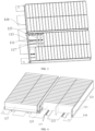
FIG. 2 is a schematic diagram of a three-dimensional structure of a supporting plate of a power battery pack in an embodiment of the present application; -
FIG. 3 is a schematic diagram of a three-dimensional structure of a power battery pack in an embodiment of the present application; -
FIG. 4 is a schematic diagram of a three-dimensional structure of a pressure relief groove of a power battery pack in an embodiment of the present application; -
FIG. 5 is a schematic diagram of an explosion structure of a power battery pack in another embodiment of the present application; -
FIG. 6 is a schematic diagram of a three-dimensional structure of a first cooling plate of a power battery pack in an embodiment of the present application; -
FIG. 7 is a schematic diagram of a top view structure of a runner plate of a power battery pack in another embodiment of the present application; -
FIG. 8 is a schematic diagram of a top view structure of a cooling flat plate of a power battery pack in another embodiment of the present application; -
FIG. 9 is a schematic diagram of a three-dimensional structure of a power battery pack without a second cooling plate in another embodiment of the present application. - 100. Power battery pack; 110. Supporting plate; 111. Pressure relief groove; 113. Pressure relief hole; 115. Pressure relief channel; 117. Pressure relief cavity; 120. Module; 121. Battery cell; 123. Thermal insulation pad; 125. Explosion-proof valve; 127. Module end plate; 130. Bottom protective plate; 140. Box body; 141. Transverse partition plate; 143. Longitudinal partition plate; 1401. Side clearance; 150. Spacer; 160. Module pressure relief valve; 170. Electrical assembly; 180. Box pressure relief valve; 191. First cooling plate; 1911. Runner plate; 1913. Cooling flat plate; 193. Second cooling plate; Avoidance groove, 1901; Baffle, 1903.
- The technical solutions in the present application will be clearly and completely described below in conjunction with the drawings. Apparently, the described embodiments are part of, but not all of, the embodiments of the present application. Based on the embodiments of the present application, all other embodiments obtained by those of ordinary skill in the art without creative work are included in the protection scope of the present application.
- As shown in
FIGs. 1 to 3 , apower battery pack 100 includes a supportingplate 110 and amodule 120. The supportingplate 110 is provided with apressure relief groove 111, thepressure relief groove 111 has a plurality ofpressure relief cavities 117 arranged in sequence along a length direction thereof, and eachpressure relief cavity 117 is provided with at least onepressure relief hole 113 in each side wall on each of two opposite sides of thepressure relief groove 111. Themodule 120 includes a plurality ofbattery cells 121 arranged in sequence, eachbattery cell 121 corresponds to apressure relief cavity 117, and eachbattery cell 121 is provided with an explosion-proof valve 125 which is partially positioned in thepressure relief cavity 117. - The supporting
plate 110 has a uniform thickness. Thepressure relief groove 111 extends from a first side of the supportingplate 110 to an opposite second side, wherein the first side is opposite to the second side. Thepressure relief groove 111 has a groove bottom and two opposite side walls, and thepressure relief hole 113 is formed in the side wall and close to the groove bottom. The plurality ofpressure relief holes 113 are formed in sequence along a length direction of thepressure relief groove 111. Themodule 120 includes the plurality ofbattery cells 121, and the explosion-proof valve 125 is arranged at a bottom of eachbattery cell 121. When themodule 120 is placed on the supportingplate 110, the plurality ofbattery cells 121 are arranged along the length direction of thepressure relief groove 111, and the explosion-proof valve 125 of eachbattery cell 121 is opposite to thepressure relief groove 111. When thebattery cell 121 abuts against the supportingplate 110, themodule 120 and thepressure relief cavity 117 formed by thepressure relief groove 111 can accommodate part of the explosion-proof valve 125, and an opening position of thepressure relief hole 113 is away from the explosion-proof valve 125. When thermal runaway occurs to asingle battery cell 121, as a sealed and independentpressure relief cavity 117 is already formed at the position of the explosion-proof valve 125 of the runaway battery cell, a high-temperature gas can only be discharged to both sides through thepressure relief holes 113 in the side wall of thepressure relief groove 111. Therefore, an electrical assembly, a water cooling pipeline and other parts in the box can be effectively protected. - Optionally, as shown in
FIGs.3 and 4 , athermal insulation pad 123 is arranged between every two neighboringbattery cells 121, thethermal insulation pad 123 extends into thepressure relief groove 111 and abuts against an inner wall of thepressure relief groove 111, so that every two neighboringthermal insulation pads 123 partition one sealedpressure relief cavity 117 in thepressure relief groove 111. - As shown in
FIG.4 , the bottom of thethermal insulation pad 123 protrudes to form a protruding structure, and the protruding structure of thethermal insulation pad 123 is attached to the side walls and the bottom wall on two sides of thepressure relief groove 111, so as to form an independentpressure relief cavity 117 for a single battery cell. Althoughpressure relief holes 113 are also present in thepressure relief cavities 117 corresponding to the neighboringbattery cells 121, as thepressure relief cavities 117 corresponding to the neighboringbattery cells 121 are sealed, it is difficult for the high-temperature gas to enter, and the high-temperature gas is discharged along thepressure relief channels 115 on both sides. - Optionally, the supporting
plate 110 has a structure of a plate body, a part of the plate body of the supportingplate 110 is inwardly recessed to form thepressure relief groove 111, and themodule 120 is attached to another part, which protrudes relative to thepressure relief groove 111, of the plate body of the supportingplate 110. - Optionally, the
pressure relief groove 111 may be formed by the supportingplate 110 being recessed toward one side of the plate surface, and two opposite sides of thepressure relief groove 111 are protruded relative to thepressure relief groove 111. The protruded parts have flat surfaces and may be used for bonding with thebattery cells 121 of themodule 120. - Optionally, an area of a cross section of the
pressure relief hole 113 gradually decreases in a direction from the inner wall to an outer wall of thepressure relief groove 111, and the cross section of thepressure relief hole 113 is a section perpendicular to a central axis of thepressure relief hole 113. - The area of the cross section of the
pressure relief hole 113 gradually decreases from the inner side wall to the outer part of thepressure relief groove 111, so that thepressure relief hole 113 has a structure of a bell. Specifically, the area of the cross section of thepressure relief hole 113 close to the inner side wall of thepressure relief groove 111 is greater than that far from the inner side wall of thepressure relief groove 111. The cross section of thepressure relief hole 113 is a plane perpendicular to the central axis of thepressure relief hole 113. Thepressure relief hole 113 may be a strip-shaped hole, and the bell-mouth shape of thepressure relief hole 113 will increase difficulty for the hot gas to enter thepressure relief cavity 117 corresponding to thepressure relief hole 113 from the outside, so that, when thermal runaway occurs to asingle battery cell 121, the hot gas is not discharged to the neighboringbattery cell 121. - Optionally, a one-way membrane structure or a one-way valve is arranged at the
pressure relief hole 113. The one-way membrane structure is made of mica, and the gas in thepressure relief cavity 117 can break through the one-way membrane structure and be discharged to the outside, but cannot return to the pressure relief cavity. In addition, the one-way membrane structure can also be replaced by the one-way valve, so that the gas can only be discharged to the outside from thepressure relief cavity 117 through the one-way membrane structure, and not discharged to thepressure relief cavity 117 through the one-way membrane structure. Therefore, the difficulty for the hot gas to enter thepressure relief cavity 117 corresponding to thepressure relief hole 113 from the outside can also be increased. - Optionally, as shown in
FIG.5 , the power battery pack further includes afirst cooling plate 191, thefirst cooling plate 191 is provided with anavoidance groove 1901, abaffle 1903 is arranged at one end of theavoidance groove 1901, thepressure relief groove 111 penetrates through theavoidance groove 1901, thebaffle 1903 shields one end of thepressure relief groove 111, thepressure relief hole 113 is arranged to avoid theavoidance groove 1901, and thefirst cooling plate 191 is connected to the supportingplate 110. - The
first cooling plate 191 may be a water cooling plate, and thefirst cooling plate 191 may be adhered to the supportingplate 110 by means of a heat-conducting structure to cool thebattery cell 121. Theavoidance grooves 1901 in thefirst cooling plate 191 correspond to thepressure relief grooves 111 one by one, and thefirst cooling plate 191 can be connected to the supportingplate 110 in an adhesive manner. Theavoidance groove 1901 is sleeved outside thepressure relief groove 111, and thepressure relief hole 113 is arranged to avoid the side wall of theavoidance groove 1901, so that the gas can be discharged from thepressure relief hole 113. Thebaffle 1903 is arranged at one end of theavoidance groove 1901, thebaffle 1903 can block one end of thepressure relief groove 111, and the other end of thepressure relief groove 111 can abut against the side wall of abox body 140, and therefore, thepressure relief groove 111 can form a sealing groove. Themodule 120 can be cooled by thefirst cooling plate 191, and quality of thepower battery pack 100 can be improved. - The
first cooling plate 191 may be flanged by a seal to prevent other impurities from being discharged into space between the supportingplate 110 and the bottom protective plate 130. Corresponding to thepressure relief groove 111, a modulepressure relief valve 160 and a boxpressure relief valve 180 may be arranged on a side wall of thebox body 140. - Optionally, as shown in
FIGs. 6, 7 and8 , thefirst cooling plate 191 includes: arunner plate 1911 and a coolingflat plate 1913, wherein therunner plate 1911 is provided with a first groove; and the coolingflat plate 1913 is provided with a second groove, the coolingflat plate 1913 is buckled on therunner plate 1911, so that the second groove is positioned opposite to the first groove to form theavoidance groove 1901. - The cooling
flat plate 1913 can be used to support the supportingplate 110. Therunner plate 1911 and the coolingflat plate 1913 can be made of aluminum, and the supportingplate 110 can be made of a steel plate. - As shown in
FIG. 5 , the power battery pack further includes asecond cooling plate 193, thesecond cooling plate 193 and thefirst cooling plate 191 are oppositely arranged on two opposite sides of themodule 120. - The
second cooling plate 193 may be a water cooling plate or a flat plate. Thesecond cooling plate 193 is bonded to themodule 120, and thesecond cooling plate 193 and thefirst cooling plate 191 are arranged oppositely, so as to form dual cooling on themodule 120, and achieve a better cooling effect. - Optionally, as shown in
FIG.5 , the power battery pack further includes a bottom protective plate 130, the supportingplate 110 is arranged on the bottom protective plate 130, and apressure relief channel 115 is formed between the bottom protective plate 130 and the supportingplate 110. - It can be understood that the bottom protective plate 130 and the supporting
plate 110 are respectively have a structure of a plate, the plate surface of the bottom protective plate 130 can be a plane, and the outer surface of the bottom wall of thepressure relief groove 111 also has a plane, so that the bottom wall of thepressure relief groove 111 is conveniently bonded with the bottom protective plate 130. The outer surface of the groove bottom of thepressure relief groove 111 of the supportingplate 110 is attached to the bottom protective plate 130, and parts of the supportingplate 110 located at the two opposite sides of thepressure relief groove 111 respectively protrude in a direction away from the bottom protective plate 130, so as to form thepressure relief channel 115 between the supportingplate 110 and the bottom protective plate 130. Thepressure relief hole 113 has a shape of a bell mouth, so that the hot gas entering thepressure relief channel 115 is prevented or reduced from entering otherpressure relief cavities 117 and the hot gas can be discharged along thepressure relief channels 115 on two sides. - The
pressure relief channel 115 is arranged on at least one side of the two opposite sides of thepressure relief groove 111, and thepressure relief channel 115 extends from the first side to the second side of the supportingplate 110, the protruding part of the supportingplate 110 relative to thepressure relief groove 111 is arranged away from the bottom protective plate 130, and a bottom clearance is formed with the bottom protective plate 130 and bottom clearances on the two opposite sides of thepressure relief groove 111 form thepressure relief channel 115. The protruding part of the supportingplate 110 relative to thepressure relief groove 111 has a convex plane abutting against thebattery cell 121, which enables themodule 120 to be supported on the supportingplate 110. The groove bottom of the groove can also be a plane, which is beneficial for the supportingplate 110 to be supported on the bottom protective plate 130. - Of course, if the bottom protective plate 130 is removed, only the supporting
plate 110 can protect themodule 120, and the one-way membrane structure or the one-way valve can isolate the explosion-proof valve 125 from external space, and in this way, the hot gas can be directly discharged to the atmosphere outside thepressure relief cavity 117 if thermal runaway occurs to asingle battery cell 121. - Optionally, as shown in
FIGs. 1 and9 , the power battery pack further includes abox body 140, atransverse partition plate 141 is arranged in thebox body 140, thetransverse partition plate 141 separates an accommodating cavity and aside clearance 1401 in thebox body 140, themodule 120 is arranged in the accommodating cavity, and anelectrical assembly 170 is arranged in theside clearance 1401. - The
box body 140 has a cubic structure, thetransverse partition plate 141 and alongitudinal partition plate 143 are arranged in thebox body 140, thelongitudinal partition plate 143 separates two areas in the accommodating cavity, and each area is provided with amodule 120. - Optionally, as shown in
FIG. 9 , the power battery pack further includes aspacer 150 and a modulepressure relief valve 160, thespacer 150 is arranged in theside clearance 1401, thespacer 150 is buckled with thepressure relief groove 111, an end surface of one end of thespacer 150 abuts against thetransverse partition plate 141, and an end surface of the other opposite end of thespacer 150 abuts against the inner wall of thebox body 140; the modulepressure relief valve 160 is arranged on thebox body 140, and the modulepressure relief valve 160 is arranged corresponding to thepressure relief groove 111, and theelectrical assembly 170 abuts against thespacer 150. - The
spacer 150 is used to extend thepressure relief groove 111 corresponding to thebattery cell 121 in theside clearance 1401. As the modulepressure relief valve 160 corresponding to thepressure relief groove 111 is arranged on thebox body 140, the modulepressure relief valve 160 can relieve pressure of the gas entering thepressure relief groove 111. - Optionally, as shown in
FIG. 5 , the power battery pack further includes a boxpressure relief valve 180, the boxpressure relief valve 180 is arranged on thebox body 140, and the boxpressure relief valve 180 is adapted to relieve pressure of thebox body 140. - The box
pressure relief valve 180 can relieve pressure of flue gas discharged from a clearance of the independent channel. - The battery pack mainly includes the bottom protective plate 130, the supporting
plate 110, themodule 120, thebox body 140, thespacer 150, theelectrical assembly 170, a high and low voltage connector, the pressure relief valve, thefirst cooling plate 191, and thesecond cooling plate 193. - As shown in
FIG. 9 , thebox body 140 is provided with across beam 141 and alongitudinal beam 143 in the middle. A basic installation process is inverted installation: after thebox body 140 is pre-installed with the pressure relief valve, the water cooling pipe connector and other parts, thesecond cooling plate 193 is installed first, a heat-conducting structural adhesive is applied to a sub-channel position of thesecond cooling plate 193, the assembledmodule 120 is lifted into the box for laminating and curing; then, electrical parts and the water cooling pipeline in thebox body 140 are installed, the structural adhesive is applied to a corresponding position of a contact surface between the bottom of thebattery cell 121 and the supportingplate 110, a bottom assembly in which the supportingplate 110 is welded to the bottom protective plate 130 is then installed, bolt fastening/FDS fastening is performed, and laminating and curing are performed. Of course, after themodule 120 is installed, the single supportingplate 110 can also be first bonded to the bottom of themodule 120, and after curing as a whole, the whole is lifted into the box for bonding and curing through lifting holes in a lifting plate, and then thefirst cooling plate 191 is installed after the structural adhesive is applied to the contact surface between the supportingplate 110 and the bottom protective plate 130, and finally the bottom protective plate 130 is installed. This mode is a full bonding mode. Thespacer 150 may be separately installed at the end, or may be integrated onto thebox body 140. After installation, an independent channel of themodule 120 has a clearance that cannot be completely sealed, and the flue gas discharged from the fame does not pass through the narrow clearance, and the pressure is relieved by the boxpressure relief valve 180 in the space of thebox body 140. - The
module 120 is basically composed of thebattery cells 121, thethermal insulation pads 123 between thebattery cells 121, the partition plates,module end plates 127, a CCS assembly, and a CCS assembly protective cover. The CCS assembly is composed of a busbar, an FPC and a bracket, or a busbar, an FFC and a PET fixing membrane. - The supporting
plate 110 is made of a thin spring steel, and a thickness of the supportingplate 110 is 0.3 mm to 0.8 mm, or the supportingplate 110 is made of a low-strength energy-absorbing plate, and is pre-welded to the bottom protective plate 130. The explosion-proof valve 125 of the battery cell is located right in thepressure relief groove 111 to form thepressure relief groove 111 with the independentpressure relief cavity 117. The side wall of thepressure relief groove 111 is provided with holes, an opening position is far away from the explosion-proof valve, and a shape of the hole can be a bell mouth under stretching treatment, so as to reduce influences of thermal runaway of a battery cell on neighboring battery cells. At the same time, the bottom of thethermal insulation pad 123 is made to have a protruding structure, and the protrusion of the thermal insulation pad is attached to the side wall of thepressure relief groove 111, so as to form an independent battery cellpressure relief cavity 117 for a single battery cell. When thermal runaway occurs to a single battery cell, as a sealed independent battery cellpressure relief cavity 117 is already formed at the position of the pressure relief valve of the runaway battery cell, the high-temperature gas can only be discharged to thepressure relief channel 115 through thepressure relief holes 113 in the side wall; the influence on the neighboring battery cells: thepressure relief channel 115 and thebattery cell 121 are protected by the supportingplate 110, which reduces spread of heat. Although the neighboring battery cells also have exhaust holes in the side wall of the pressure relief cavity, as thepressure relief cavity 117 of the neighboring battery cells is internally sealed, the high-temperature gas is difficult to enter, and the bell mouth shape of thepressure relief hole 113 also increases the difficulty for the hot gas to enter, so that the hot gas is discharged along thepressure relief channel 115. Thepressure relief channel 115 is provided with an independent pressure relief valve, thepressure relief channel 115 is formed by thepressure relief spacer 150 arranged on the box body, and thepressure relief channel 115 is basically sealed, so that the electrical assembly, the water cooling pipeline and other parts in the box can be effectively protected. In addition to the pressure relief valve of the independent channel, the boxpressure relief valve 180 is additionally installed on thebox body 140, which can be used to relieve the pressure of the flue gas discharged from the clearance of the independent channel. - Optionally, one side of the
second cooling plate 193 facing the bottom protective plate 130 is provided with a heat-conducting structure, wherein the heat-conducting structure can be attached to thesecond cooling plate 193 and themodule 120, which is beneficial to heat dissipation of themodule 120. - Optionally, the heat-conducting structure includes a heat-conducting adhesive film, and the heat-conducting adhesive film is attached to a side of the
second cooling plate 193 facing the bottom protective plate 130. The heat-conducting structural adhesive can be made of a polyurethane heat-conducting structural adhesive or a modified epoxy heat-conducting structural adhesive, and the heat-conducting structural adhesive is film-shaped and has a good heat-conducting effect. - An electrical apparatus includes a
power battery pack 100, and thepower battery pack 100 is configured as thepower battery pack 100 according to any one of the above. When thepower battery pack 100 is applied to the electrical apparatus, thepower battery pack 100 may include themodule 120, and themodule 120 may include a plurality ofbattery cells 121. - Based on the above description, the present application has the following advantages:
- 1. The explosion-
proof valve 125 of thebattery cell 121 is opposite to thepressure relief groove 111, thebattery cell 121 and thepressure relief cavity 117 formed by thepressure relief groove 111 can accommodate part of the explosion-proof valve, the opening position of thepressure relief hole 113 is far away from the explosion-proof valve, so that, when thermal runaway occurs to asingle battery cell 121, as the sealed and independentpressure relief cavity 117 is already formed at the position of the explosion-proof valve 125 of the runaway battery cell, a high-temperature gas can only be discharged through thepressure relief holes 113 in the side wall, which can effectively protect the electrical assembly, the water cooling pipeline and other parts in the box. - 2. The
thermal insulation pad 123 is attached to the inner wall of thepressure relief groove 111 to form the independentpressure relief cavity 117, which can achieve a good protection effect. - 3. The
pressure relief hole 113 has a shape of a bell mouth or a one-way valve or a one-way membrane structure is arranged at thepressure relief hole 113, which can reduce the influence of thermal runaway on neighboring battery cells. - 4. The
first cooling plate 191 is arranged at the bottom, which can achieve a cooling effect on the battery cell and improve cooling efficiency. - 5. The
second cooling plate 193 is arranged at the top, and thesecond cooling plate 193 is cooperated with thefirst cooling plate 191, which can achieve a dual cooling effect on themodule 120, and further improve the cooling efficiency. - 6. By adding the bottom protective plate 130, the supporting
plate 110 is not only further supported, thepressure relief channel 115 can also be formed, so that the hot gas can be discharged from thepressure relief channel 115, which is conducive to treatment of the discharged gas, thus optimizing the ambient air. - In the description of the present application, it should be noted that the orientations or positional relationships indicated by the terms "center", "upper", "lower", "left", "right", "vertical", "horizontal", "inner", "outer", etc. are based on those shown in the accompanying drawings, and are intended only to facilitate the description of the present application and to simplify the description, and are not intended to indicate or imply that the apparatus or element referred to must have a particular orientation, be constructed and operated in a particular orientation, and therefore are not to be construed as a limitation of the present application. Furthermore, the terms "first", "second" and "third" are used for descriptive purposes only and are not to be understood as indicating or implying relative importance.
- In the description of the present application, it is to be noted that, unless otherwise expressly specified and limited, the terms "install", "mutually connect", "connect" are to be understood in a broad sense, for example, which may refer to a fixed connection or a detachable connection or an integral connection; which may refer to a mechanical connection or an electric connection; which may refer to a direct connection or an indirect connection by means of intermediate components or a communication within two elements. For those of ordinary skill in the art, the specific meanings of the above terms in the present application can be understood according to specific circumstances.
- In addition, the technical features involved in different embodiments of the present application described below may be combined with each other as long as they do not conflict with each other.
- Apparently, the above embodiments are merely examples for clarity of illustration and are not limitations of the embodiments. For those of ordinary skill in the art, other variations or modifications in different forms can be made on the basis of the above description. It is not necessary or possible to exhaustively list all embodiments here. And obvious variations or modifications thereof are intended to remain within the scope of protection of the present application.
Claims (10)
- A power battery pack (100), comprising:a supporting plate (110), provided with a pressure relief groove (111), the pressure relief groove (111) having a plurality of pressure relief cavities (117) arranged in sequence along a length direction thereof, and each pressure relief cavity (117) being provided with at least one pressure relief hole (113) in each side wall on each of two opposite sides of the pressure relief groove (111); anda module (120), comprising a plurality of battery cells (121) arranged in sequence, each battery cell (121) corresponding to one pressure relief cavity (117), and each battery cell (121) being provided with an explosion-proof valve (125) which is partially positioned in the pressure relief cavity (117).
- The power battery pack (100) according to claim 1, wherein a thermal insulation pad (123) is arranged between every two neighboring battery cells (121), the thermal insulation pad (123) extending into the pressure relief groove (111) and abutting against an inner wall of the pressure relief groove (111), so that every two neighboring thermal insulation pads (123) partition one pressure relief cavity (117) in the pressure relief groove (111).
- The power battery pack (100) according to claim 1, wherein the supporting plate (110) has a structure of a plate body, a part of the plate body of the supporting plate (110) being inwardly recessed to form the pressure relief groove (111), and the module (120) being attached to aother part, which protrudes relative to the pressure relief groove (111), of the plate body of the supporting plate (110).
- The power battery pack (100) according to any one of claims 1 to 3, wherein an area of a cross section of the pressure relief hole (113) gradually decreases in a direction from an inner wall to an outer wall of the pressure relief groove (111), the cross section of the pressure relief hole (113) being a section perpendicular to a central axis of the pressure relief hole (113).
- The power battery pack (100) according to any one of claims 1 to 3, wherein a one-way membrane structure or a one-way valve is arranged at the pressure relief hole (113).
- The power battery pack (100) according to any one of claims 1 to 3, further comprising a first cooling plate (191), wherein the first cooling plate (191) is provided with an avoidance groove (1901), a baffle (1903) is provided at one end of the avoidance groove (1901), the pressure relief groove (111) penetrates through the avoidance groove (1901), the baffle (1903) shields one end of the pressure relief groove (111), the pressure relief hole (113) is arranged to avoid the avoidance groove (1901), and the first cooling plate (191) is connected to the supporting plate (110).
- The power battery pack (100) according to claim 6, wherein the first cooling plate (191) comprises:a runner plate (1911), provided with a first groove; anda cooling flat plate (1913), provided with a second groove, the cooling flat plate (1913) being buckled on the runner plate (1911), so that the second groove is positioned opposite to the first groove to form the avoidance groove (1901).
- The power battery pack (100) according to claim 6, further comprising a second cooling plate (193), wherein the second cooling plate (193) and the first cooling plate (191) are oppositely arranged on two opposite sides of the module (120).
- The power battery pack (100) according to any one of claims 1 to 3, further comprising a bottom protective plate (130), wherein the bottom protective plate (130) abuts against an outer wall of a groove bottom of the pressure relief groove (111), so that a pressure relief channel (115) is formed along each of two opposite sides, in a width direction, of the pressure relief groove (111).
- An electrical apparatus, comprising a power battery pack (100), wherein the power battery pack (100) is configured as the power battery pack (100) according to any one of claims 1 to 9.
Applications Claiming Priority (2)
| Application Number | Priority Date | Filing Date | Title |
|---|---|---|---|
| CN202223470196.XU CN219067128U (en) | 2022-12-23 | 2022-12-23 | Power battery pack and electrical device |
| PCT/CN2023/141654 WO2024131988A1 (en) | 2022-12-23 | 2023-12-25 | Power battery pack and electric device |
Publications (2)
| Publication Number | Publication Date |
|---|---|
| EP4425673A1 true EP4425673A1 (en) | 2024-09-04 |
| EP4425673A4 EP4425673A4 (en) | 2025-04-23 |
Family
ID=86372210
Family Applications (1)
| Application Number | Title | Priority Date | Filing Date |
|---|---|---|---|
| EP23892762.8A Pending EP4425673A4 (en) | 2022-12-23 | 2023-12-25 | POWER SUPPLY BATTERY PACK AND ELECTRICAL DEVICE |
Country Status (4)
| Country | Link |
|---|---|
| US (1) | US20260058298A1 (en) |
| EP (1) | EP4425673A4 (en) |
| CN (1) | CN219067128U (en) |
| WO (1) | WO2024131988A1 (en) |
Families Citing this family (11)
| Publication number | Priority date | Publication date | Assignee | Title |
|---|---|---|---|---|
| CN219067128U (en) * | 2022-12-23 | 2023-05-23 | 蜂巢能源科技股份有限公司 | Power battery pack and electrical device |
| CN220138605U (en) * | 2023-06-28 | 2023-12-05 | 蜂巢能源科技股份有限公司 | Battery pack |
| KR20250008235A (en) * | 2023-07-07 | 2025-01-14 | 주식회사 엘지에너지솔루션 | Battery pack |
| CN220627997U (en) * | 2023-07-24 | 2024-03-19 | 惠州亿纬锂能股份有限公司 | Cooling system and battery pack |
| WO2025045155A1 (en) * | 2023-08-29 | 2025-03-06 | 蜂巢能源科技股份有限公司 | Battery pack, battery pack assembly, and power device |
| WO2025060391A1 (en) * | 2023-09-18 | 2025-03-27 | 惠州亿纬锂能股份有限公司 | Battery pack and vehicle |
| CN221327956U (en) * | 2023-10-31 | 2024-07-12 | 欣旺达动力科技股份有限公司 | Battery packs and electrical equipment |
| CN120613537A (en) * | 2024-03-06 | 2025-09-09 | 宁德时代新能源科技股份有限公司 | Battery pack, battery module, battery unit and power-consuming device |
| CN118431663B (en) * | 2024-07-03 | 2024-11-19 | 浙江晶科储能有限公司 | Battery pack and energy storage system |
| CN223156112U (en) * | 2024-07-31 | 2025-07-25 | 武汉亿纬储能有限公司 | Liquid cooling plate and battery |
| CN119786844B (en) * | 2024-09-27 | 2025-10-31 | 比亚迪股份有限公司 | Battery fixing plate, battery pack and electric equipment |
Family Cites Families (10)
| Publication number | Priority date | Publication date | Assignee | Title |
|---|---|---|---|---|
| CN107134557B (en) * | 2017-06-16 | 2023-06-09 | 宁波利维能储能系统有限公司 | Battery module and battery module |
| CN207677016U (en) * | 2017-06-16 | 2018-07-31 | 宁波利维能储能系统有限公司 | Heat dissipation structure of battery module cells |
| DE102017212223A1 (en) * | 2017-07-18 | 2019-01-24 | Bayerische Motoren Werke Aktiengesellschaft | BATTERY OF AN ELECTRICALLY DRIVEN MOTOR VEHICLE |
| DE102019207084A1 (en) * | 2019-05-15 | 2020-11-19 | Audi Ag | Battery module, high-voltage battery and motor vehicle |
| JP7403561B2 (en) * | 2021-03-23 | 2023-12-22 | 寧徳時代新能源科技股▲分▼有限公司 | Battery case, battery, power consumption device, battery manufacturing method and device |
| EP4456300A4 (en) * | 2022-01-25 | 2025-04-02 | Contemporary Amperex Technology (Hong Kong) Limited | Battery, electric device, and battery manufacturing method and device |
| CN217334327U (en) * | 2022-05-16 | 2022-08-30 | 小米汽车科技有限公司 | Battery pack and vehicle |
| CN219163626U (en) * | 2022-12-23 | 2023-06-09 | 蜂巢能源科技股份有限公司 | Battery pack and power device |
| CN219067128U (en) * | 2022-12-23 | 2023-05-23 | 蜂巢能源科技股份有限公司 | Power battery pack and electrical device |
| KR102795117B1 (en) * | 2023-03-31 | 2025-04-10 | 삼성에스디아이 주식회사 | Battery module |
-
2022
- 2022-12-23 CN CN202223470196.XU patent/CN219067128U/en active Active
-
2023
- 2023-12-25 EP EP23892762.8A patent/EP4425673A4/en active Pending
- 2023-12-25 US US18/850,343 patent/US20260058298A1/en active Pending
- 2023-12-25 WO PCT/CN2023/141654 patent/WO2024131988A1/en not_active Ceased
Also Published As
| Publication number | Publication date |
|---|---|
| WO2024131988A1 (en) | 2024-06-27 |
| EP4425673A4 (en) | 2025-04-23 |
| US20260058298A1 (en) | 2026-02-26 |
| CN219067128U (en) | 2023-05-23 |
Similar Documents
| Publication | Publication Date | Title |
|---|---|---|
| EP4425673A1 (en) | Power battery pack and electric device | |
| KR102386917B1 (en) | Battery module and its manufacturing method | |
| CN211350900U (en) | battery module | |
| EP3790070B1 (en) | Battery pack, method for manufacturing same, and vehicle | |
| CN216529223U (en) | a battery pack | |
| US20230108623A1 (en) | Battery pack and vehicle | |
| KR20220051147A (en) | Battery module and its manufacturing method | |
| EP2738834B1 (en) | Battery pack | |
| KR20220092581A (en) | Devices using battery modules, battery packs and secondary batteries | |
| EP4447197A1 (en) | Battery cooling system, battery pack, and vehicle | |
| KR102922440B1 (en) | Battery Pack With Improved Battery Cell Lifetime And Device Including It | |
| US12476325B2 (en) | Cell assembly unit and battery pack including the same | |
| CN212230472U (en) | Power battery pack and vehicle with the same | |
| KR20240123299A (en) | Battery module and battery pack including the same | |
| US11296385B2 (en) | Battery module and battery pack | |
| CN113036276B (en) | Battery Packs and Electric Vehicles | |
| JP7387204B2 (en) | Battery packs and devices containing them | |
| EP4372891A1 (en) | Battery device and preparation method therefor | |
| CN222530669U (en) | Battery Pack | |
| KR102767703B1 (en) | Battery pack and device including the same | |
| EP4525144A1 (en) | Battery pack | |
| KR20240114910A (en) | Battery pack | |
| CN212257515U (en) | Electric core isolation device of power battery pack of portable battery-replacing electric vehicle and power battery pack | |
| JP7638338B2 (en) | Battery pack | |
| CN223079195U (en) | Battery pack |
Legal Events
| Date | Code | Title | Description |
|---|---|---|---|
| STAA | Information on the status of an ep patent application or granted ep patent |
Free format text: STATUS: UNKNOWN |
|
| STAA | Information on the status of an ep patent application or granted ep patent |
Free format text: STATUS: THE INTERNATIONAL PUBLICATION HAS BEEN MADE |
|
| PUAI | Public reference made under article 153(3) epc to a published international application that has entered the european phase |
Free format text: ORIGINAL CODE: 0009012 |
|
| STAA | Information on the status of an ep patent application or granted ep patent |
Free format text: STATUS: REQUEST FOR EXAMINATION WAS MADE |
|
| 17P | Request for examination filed |
Effective date: 20240529 |
|
| AK | Designated contracting states |
Kind code of ref document: A1 Designated state(s): AL AT BE BG CH CY CZ DE DK EE ES FI FR GB GR HR HU IE IS IT LI LT LU LV MC ME MK MT NL NO PL PT RO RS SE SI SK SM TR |
|
| A4 | Supplementary search report drawn up and despatched |
Effective date: 20250320 |
|
| RIC1 | Information provided on ipc code assigned before grant |
Ipc: H01M 50/244 20210101ALI20250314BHEP Ipc: H01M 50/30 20210101AFI20250314BHEP |
|
| GRAP | Despatch of communication of intention to grant a patent |
Free format text: ORIGINAL CODE: EPIDOSNIGR1 |
|
| STAA | Information on the status of an ep patent application or granted ep patent |
Free format text: STATUS: GRANT OF PATENT IS INTENDED |
|
| INTG | Intention to grant announced |
Effective date: 20260129 |
|
| DAV | Request for validation of the european patent (deleted) | ||
| DAX | Request for extension of the european patent (deleted) | ||
| GRAS | Grant fee paid |
Free format text: ORIGINAL CODE: EPIDOSNIGR3 |
|
| GRAA | (expected) grant |
Free format text: ORIGINAL CODE: 0009210 |
|
| STAA | Information on the status of an ep patent application or granted ep patent |
Free format text: STATUS: THE PATENT HAS BEEN GRANTED |