EP4425664A1 - Battery module having improved structure for preventing thermal propagation - Google Patents
Battery module having improved structure for preventing thermal propagation Download PDFInfo
- Publication number
- EP4425664A1 EP4425664A1 EP23872999.0A EP23872999A EP4425664A1 EP 4425664 A1 EP4425664 A1 EP 4425664A1 EP 23872999 A EP23872999 A EP 23872999A EP 4425664 A1 EP4425664 A1 EP 4425664A1
- Authority
- EP
- European Patent Office
- Prior art keywords
- module
- pair
- thermal barrier
- busbar
- cover
- Prior art date
- Legal status (The legal status is an assumption and is not a legal conclusion. Google has not performed a legal analysis and makes no representation as to the accuracy of the status listed.)
- Pending
Links
Images


Classifications
-
- H—ELECTRICITY
- H01—ELECTRIC ELEMENTS
- H01M—PROCESSES OR MEANS, e.g. BATTERIES, FOR THE DIRECT CONVERSION OF CHEMICAL ENERGY INTO ELECTRICAL ENERGY
- H01M50/00—Constructional details or processes of manufacture of the non-active parts of electrochemical cells other than fuel cells, e.g. hybrid cells
- H01M50/20—Mountings; Secondary casings or frames; Racks, modules or packs; Suspension devices; Shock absorbers; Transport or carrying devices; Holders
- H01M50/233—Mountings; Secondary casings or frames; Racks, modules or packs; Suspension devices; Shock absorbers; Transport or carrying devices; Holders characterised by physical properties of casings or racks, e.g. dimensions
- H01M50/24—Mountings; Secondary casings or frames; Racks, modules or packs; Suspension devices; Shock absorbers; Transport or carrying devices; Holders characterised by physical properties of casings or racks, e.g. dimensions adapted for protecting batteries from their environment, e.g. from corrosion
-
- H—ELECTRICITY
- H01—ELECTRIC ELEMENTS
- H01M—PROCESSES OR MEANS, e.g. BATTERIES, FOR THE DIRECT CONVERSION OF CHEMICAL ENERGY INTO ELECTRICAL ENERGY
- H01M10/00—Secondary cells; Manufacture thereof
- H01M10/60—Heating or cooling; Temperature control
- H01M10/65—Means for temperature control structurally associated with the cells
- H01M10/658—Means for temperature control structurally associated with the cells by thermal insulation or shielding
-
- H—ELECTRICITY
- H01—ELECTRIC ELEMENTS
- H01M—PROCESSES OR MEANS, e.g. BATTERIES, FOR THE DIRECT CONVERSION OF CHEMICAL ENERGY INTO ELECTRICAL ENERGY
- H01M50/00—Constructional details or processes of manufacture of the non-active parts of electrochemical cells other than fuel cells, e.g. hybrid cells
- H01M50/20—Mountings; Secondary casings or frames; Racks, modules or packs; Suspension devices; Shock absorbers; Transport or carrying devices; Holders
- H01M50/296—Mountings; Secondary casings or frames; Racks, modules or packs; Suspension devices; Shock absorbers; Transport or carrying devices; Holders characterised by terminals of battery packs
-
- H—ELECTRICITY
- H01—ELECTRIC ELEMENTS
- H01M—PROCESSES OR MEANS, e.g. BATTERIES, FOR THE DIRECT CONVERSION OF CHEMICAL ENERGY INTO ELECTRICAL ENERGY
- H01M50/00—Constructional details or processes of manufacture of the non-active parts of electrochemical cells other than fuel cells, e.g. hybrid cells
- H01M50/50—Current conducting connections for cells or batteries
- H01M50/502—Interconnectors for connecting terminals of adjacent batteries; Interconnectors for connecting cells outside a battery casing
- H01M50/503—Interconnectors for connecting terminals of adjacent batteries; Interconnectors for connecting cells outside a battery casing characterised by the shape of the interconnectors
-
- H—ELECTRICITY
- H01—ELECTRIC ELEMENTS
- H01M—PROCESSES OR MEANS, e.g. BATTERIES, FOR THE DIRECT CONVERSION OF CHEMICAL ENERGY INTO ELECTRICAL ENERGY
- H01M50/00—Constructional details or processes of manufacture of the non-active parts of electrochemical cells other than fuel cells, e.g. hybrid cells
- H01M50/50—Current conducting connections for cells or batteries
- H01M50/502—Interconnectors for connecting terminals of adjacent batteries; Interconnectors for connecting cells outside a battery casing
- H01M50/505—Interconnectors for connecting terminals of adjacent batteries; Interconnectors for connecting cells outside a battery casing comprising a single busbar
-
- H—ELECTRICITY
- H01—ELECTRIC ELEMENTS
- H01M—PROCESSES OR MEANS, e.g. BATTERIES, FOR THE DIRECT CONVERSION OF CHEMICAL ENERGY INTO ELECTRICAL ENERGY
- H01M50/00—Constructional details or processes of manufacture of the non-active parts of electrochemical cells other than fuel cells, e.g. hybrid cells
- H01M50/50—Current conducting connections for cells or batteries
- H01M50/502—Interconnectors for connecting terminals of adjacent batteries; Interconnectors for connecting cells outside a battery casing
- H01M50/507—Interconnectors for connecting terminals of adjacent batteries; Interconnectors for connecting cells outside a battery casing comprising an arrangement of two or more busbars within a container structure, e.g. busbar modules
-
- H—ELECTRICITY
- H01—ELECTRIC ELEMENTS
- H01M—PROCESSES OR MEANS, e.g. BATTERIES, FOR THE DIRECT CONVERSION OF CHEMICAL ENERGY INTO ELECTRICAL ENERGY
- H01M50/00—Constructional details or processes of manufacture of the non-active parts of electrochemical cells other than fuel cells, e.g. hybrid cells
- H01M50/50—Current conducting connections for cells or batteries
- H01M50/502—Interconnectors for connecting terminals of adjacent batteries; Interconnectors for connecting cells outside a battery casing
- H01M50/514—Methods for interconnecting adjacent batteries or cells
- H01M50/517—Methods for interconnecting adjacent batteries or cells by fixing means, e.g. screws, rivets or bolts
-
- H—ELECTRICITY
- H01—ELECTRIC ELEMENTS
- H01M—PROCESSES OR MEANS, e.g. BATTERIES, FOR THE DIRECT CONVERSION OF CHEMICAL ENERGY INTO ELECTRICAL ENERGY
- H01M50/00—Constructional details or processes of manufacture of the non-active parts of electrochemical cells other than fuel cells, e.g. hybrid cells
- H01M50/50—Current conducting connections for cells or batteries
- H01M50/502—Interconnectors for connecting terminals of adjacent batteries; Interconnectors for connecting cells outside a battery casing
- H01M50/521—Interconnectors for connecting terminals of adjacent batteries; Interconnectors for connecting cells outside a battery casing characterised by the material
- H01M50/526—Interconnectors for connecting terminals of adjacent batteries; Interconnectors for connecting cells outside a battery casing characterised by the material having a layered structure
-
- H—ELECTRICITY
- H01—ELECTRIC ELEMENTS
- H01M—PROCESSES OR MEANS, e.g. BATTERIES, FOR THE DIRECT CONVERSION OF CHEMICAL ENERGY INTO ELECTRICAL ENERGY
- H01M50/00—Constructional details or processes of manufacture of the non-active parts of electrochemical cells other than fuel cells, e.g. hybrid cells
- H01M50/50—Current conducting connections for cells or batteries
- H01M50/543—Terminals
- H01M50/547—Terminals characterised by the disposition of the terminals on the cells
- H01M50/55—Terminals characterised by the disposition of the terminals on the cells on the same side of the cell
-
- H—ELECTRICITY
- H01—ELECTRIC ELEMENTS
- H01M—PROCESSES OR MEANS, e.g. BATTERIES, FOR THE DIRECT CONVERSION OF CHEMICAL ENERGY INTO ELECTRICAL ENERGY
- H01M50/00—Constructional details or processes of manufacture of the non-active parts of electrochemical cells other than fuel cells, e.g. hybrid cells
- H01M50/50—Current conducting connections for cells or batteries
- H01M50/543—Terminals
- H01M50/564—Terminals characterised by their manufacturing process
- H01M50/567—Terminals characterised by their manufacturing process by fixing means, e.g. screws, rivets or bolts
-
- H—ELECTRICITY
- H01—ELECTRIC ELEMENTS
- H01M—PROCESSES OR MEANS, e.g. BATTERIES, FOR THE DIRECT CONVERSION OF CHEMICAL ENERGY INTO ELECTRICAL ENERGY
- H01M50/00—Constructional details or processes of manufacture of the non-active parts of electrochemical cells other than fuel cells, e.g. hybrid cells
- H01M50/50—Current conducting connections for cells or batteries
- H01M50/572—Means for preventing undesired use or discharge
- H01M50/584—Means for preventing undesired use or discharge for preventing incorrect connections inside or outside the batteries
- H01M50/59—Means for preventing undesired use or discharge for preventing incorrect connections inside or outside the batteries characterised by the protection means
- H01M50/591—Covers
-
- H—ELECTRICITY
- H01—ELECTRIC ELEMENTS
- H01M—PROCESSES OR MEANS, e.g. BATTERIES, FOR THE DIRECT CONVERSION OF CHEMICAL ENERGY INTO ELECTRICAL ENERGY
- H01M2220/00—Batteries for particular applications
- H01M2220/20—Batteries in motive systems, e.g. vehicle, ship, plane
-
- H—ELECTRICITY
- H01—ELECTRIC ELEMENTS
- H01M—PROCESSES OR MEANS, e.g. BATTERIES, FOR THE DIRECT CONVERSION OF CHEMICAL ENERGY INTO ELECTRICAL ENERGY
- H01M2220/00—Batteries for particular applications
- H01M2220/30—Batteries in portable systems, e.g. mobile phone, laptop
-
- H—ELECTRICITY
- H01—ELECTRIC ELEMENTS
- H01M—PROCESSES OR MEANS, e.g. BATTERIES, FOR THE DIRECT CONVERSION OF CHEMICAL ENERGY INTO ELECTRICAL ENERGY
- H01M50/00—Constructional details or processes of manufacture of the non-active parts of electrochemical cells other than fuel cells, e.g. hybrid cells
- H01M50/20—Mountings; Secondary casings or frames; Racks, modules or packs; Suspension devices; Shock absorbers; Transport or carrying devices; Holders
- H01M50/204—Racks, modules or packs for multiple batteries or multiple cells
- H01M50/207—Racks, modules or packs for multiple batteries or multiple cells characterised by their shape
- H01M50/209—Racks, modules or packs for multiple batteries or multiple cells characterised by their shape adapted for prismatic or rectangular cells
-
- H—ELECTRICITY
- H01—ELECTRIC ELEMENTS
- H01M—PROCESSES OR MEANS, e.g. BATTERIES, FOR THE DIRECT CONVERSION OF CHEMICAL ENERGY INTO ELECTRICAL ENERGY
- H01M50/00—Constructional details or processes of manufacture of the non-active parts of electrochemical cells other than fuel cells, e.g. hybrid cells
- H01M50/20—Mountings; Secondary casings or frames; Racks, modules or packs; Suspension devices; Shock absorbers; Transport or carrying devices; Holders
- H01M50/271—Lids or covers for the racks or secondary casings
-
- H—ELECTRICITY
- H01—ELECTRIC ELEMENTS
- H01M—PROCESSES OR MEANS, e.g. BATTERIES, FOR THE DIRECT CONVERSION OF CHEMICAL ENERGY INTO ELECTRICAL ENERGY
- H01M50/00—Constructional details or processes of manufacture of the non-active parts of electrochemical cells other than fuel cells, e.g. hybrid cells
- H01M50/50—Current conducting connections for cells or batteries
- H01M50/502—Interconnectors for connecting terminals of adjacent batteries; Interconnectors for connecting cells outside a battery casing
-
- H—ELECTRICITY
- H01—ELECTRIC ELEMENTS
- H01M—PROCESSES OR MEANS, e.g. BATTERIES, FOR THE DIRECT CONVERSION OF CHEMICAL ENERGY INTO ELECTRICAL ENERGY
- H01M50/00—Constructional details or processes of manufacture of the non-active parts of electrochemical cells other than fuel cells, e.g. hybrid cells
- H01M50/50—Current conducting connections for cells or batteries
- H01M50/543—Terminals
-
- Y—GENERAL TAGGING OF NEW TECHNOLOGICAL DEVELOPMENTS; GENERAL TAGGING OF CROSS-SECTIONAL TECHNOLOGIES SPANNING OVER SEVERAL SECTIONS OF THE IPC; TECHNICAL SUBJECTS COVERED BY FORMER USPC CROSS-REFERENCE ART COLLECTIONS [XRACs] AND DIGESTS
- Y02—TECHNOLOGIES OR APPLICATIONS FOR MITIGATION OR ADAPTATION AGAINST CLIMATE CHANGE
- Y02E—REDUCTION OF GREENHOUSE GAS [GHG] EMISSIONS, RELATED TO ENERGY GENERATION, TRANSMISSION OR DISTRIBUTION
- Y02E60/00—Enabling technologies; Technologies with a potential or indirect contribution to GHG emissions mitigation
- Y02E60/10—Energy storage using batteries
Definitions
- the present invention relates to a battery module, which is capable of effectively preventing the thermal propagation of thermal runaway occurring in a battery cell within the battery module to other surrounding battery modules.
- secondary batteries can be recharged, and they have been heavily researched and developed in recent years due to their potential for miniaturization and large capacity.
- the demand for secondary batteries as an energy source is increasing rapidly due to the technological development and increasing demand for mobile devices, electric vehicles, and energy storage systems, which are emerging in response to the need for environmental protection.
- Secondary batteries are categorized into coin-type cells, cylindrical cells, prismatic cells, and pouch-type cells based on the shape of the cell case.
- an electrode assembly mounted inside the battery case is a chargeable/dischargeable power generator consisting of a laminated structure of electrodes and separators.
- the present invention aims to provide a battery module that can more effectively block conductive dust, gases, and flames that are emitted in large quantities from high-voltage terminals by keeping the thermal barrier firmly in place in the event of thermal runaway in the battery module.
- the present invention relates to a battery module which, in one example, includes a module housing accommodating a plurality of battery cells; a pair of high-voltage terminals provided on the front of the module housing; a pair of module lifting holes provided between the pair of high-voltage terminals; a thermal barrier that wraps around part of a front of the module housing including the pair of high-voltage terminals, with a pair of fastening holes penetrating through an upper surface of the thermal barrier; and a pair of fastening members respectively penetrating through the pair of module lifting holes and pair of fastening holes to secure the thermal barrier to the module housing.
- the pair of module lifting holes are formed on an upper surface of pair of module lifting ribs that each create an open space on the front of the module housing, while forming a step relative to an upper surface of the module housing.
- the thermal barrier may form a bent shape that wraps around an upper surface and a front surface of the pair of high-voltage terminals.
- a width of the thermal barrier may correspond to a front width of the module housing.
- each fastening member may include a nut inserted inside the module lifting rib, a washer placed on the upper surface of the module lifting rib, and a bolt that screws into the nut through the fastening hole, the washer, and the module lifting hole.
- the nut is installed inside the module lifting rib in a manner that prevents it from rotating together with the rotation of the bolt.
- each fastening member may be a rivet installed through a respective fastening hole and a respective module lifting hole.
- a heat-resistant silicone may be applied to a contact surface between the thermal barrier and the module housing.
- the battery module further includes a busbar, and a busbar cover that wraps around the busbar, wherein ends of the busbar are mechanically fixed to the pair of high-voltage terminals of adjacent module housing, respectively.
- the busbar cover may include a lower busbar cover in which the busbar is seated, and is provided with a connection hole exposing the busbar to the pair of high-voltage terminals; and an upper busbar cover for wrapping around the busbar in combination with the lower busbar cover, and is provided with a pair of cover fastening holes corresponding to the module lifting holes.
- the lower busbar cover and the upper busbar cover may be mutually coupled by a hook structure.
- thermal barrier may wrap around the busbar cover.
- each fastening member may be fastened to a respective module lifting hole through a respective fastening hole in the thermal barrier and through a respective cover fastening hole in the busbar cover.
- Such a fastening member may be a nut inserted into the interior of the module lifting rib, and a bolt threaded to the nut through the respective fastening hole in the thermal barrier, through the respective cover fastening hole, and through the respective module lifting hole, or a rivet installed through the respective fastening hole in the thermal barrier, through the respective cover fastening hole, and through the respective module lifting hole.
- a concave stepped surface may be formed corresponding to the step formed by a respective one of the pair of module lifting ribs relative to the upper surface of the module housing.
- the battery module of the present invention with the above configuration can mechanically secure the thermal barrier by utilizing the module lifting holes already provided in the module housing for handling heavy battery modules.
- the thermal barrier may remain firmly in place, effectively blocking or delaying heat propagation to other battery modules in the vicinity.
- the battery module of the present invention enables even more effective prevention of heat propagation.
- the present invention relates to a battery module which, in one example, includes a module housing accommodating a plurality of battery cells; a pair of high-voltage terminals provided on the front of the module housing; a pair of module lifting holes provided between the high-voltage terminals; a thermal barrier that wraps around part of the front of the module housing including the high-voltage terminals, with fastening holes penetrating through its upper surface; and a fastening member installed by penetrating through the module lifting hole and fastening hole to secure the thermal barrier to the module lifting hole.
- the battery module of the present invention can mechanically fix the thermal barrier by utilizing the module lifting holes already provided in the module housing for handling heavy battery modules.
- the thermal barrier can remain firmly in place, effectively blocking or delaying heat propagation to other battery modules in the vicinity.
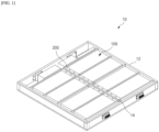
- FIG. 1 is a drawing illustrating an example of a battery pack 10 in which a plurality of battery modules 100 of the present invention is mounted.
- the battery pack 10 includes a pack case 12 made into a framed structure that forms a space for accommodating the plurality of battery modules 100 while protecting the mounted battery modules 100 and ensuring structural rigidity of the battery pack 10.
- the battery pack 10, exemplarily shown in FIG. 1 has a total of eight battery modules 100 mounted on it, with the fronts of the battery modules 100 arranged to face toward a center frame 14 that runs across the center of the pack case 12.
- a high-voltage terminal 120 for connecting a busbar 500 is arranged on the front of the battery module 100, and a thermal barrier 200 for protecting it is mounted on the battery module 100.
- FIG. 2 illustrates one battery module 100 mounted on the battery pack 10 of FIG. 1 , with the thermal barrier 200 shown in FIG. 1 omitted.
- the battery module 100 contains a plurality of battery cells (the battery cells inside are not shown in the drawing), and the plurality of battery cells are connected to each other in a series and/or parallel circuit such that charging and discharging occurs at a prescribed voltage and current.
- High-voltage terminals 120 are provided on the exterior of the battery module 100 as input and output terminals for the plurality of electrically connected battery cells.
- FIG. 3 is an enlarged view of the front of a module housing 110 in which a thermal barrier 200 is mounted.
- the module housing 110 is a portion of the body of the battery module 100 that accommodates a plurality of battery cells, and is provided with a pair of high-voltage terminals 120 on the front of the module housing 110.
- a pair of module lifting holes 132 are provided between the high-voltage terminals 120 consisting of positive electrode and negative electrode as a pair. Since the battery module 100 mounted with a plurality of battery cells can be quite heavy, a lifting device is utilized to perform storage or removal operations for the battery pack 10. For handling such a battery module 100, module lifting holes 132 are provided in the module housing 110, and for balance, a pair of module lifting holes 132 are provided at the front and rear of the module housing 110.
- the thermal barrier 200 is a bulkhead member for blocking a large amount of conductive dust, gas, and flame that is emitted at high temperature and pressure toward the high-voltage terminal 120 in the event of a thermal runaway within the battery module 100.
- the thermal barrier 200 is shaped to wrap around a front portion of the module housing 110 and is made of a flame-retardant material that can withstand high temperatures, for example, a mica material.
- the upper surface of the thermal barrier 200 has a fastening hole 210 formed through it for fixing to the module housing 110.
- the fixation of the thermal barrier 200 to the module housing 110 is accomplished by the fastening member 300, and conventionally, the thermal barrier 200 is fixed to the module housing 110 by attaching the thermal barrier 200 with an adhesive tape or heat-resistant silicone.
- the attachment method is simple, it has the disadvantage of insufficient fixing force of the thermal barrier 200, especially when the thermal barrier 200 is moved out of its position by a high-temperature/pressure spillage, thus it is difficult to trust the reliable blocking function.
- the mechanical fixity of the thermal barrier 200 is greatly improved by the fastening member 300 being installed through the module lifting hole 132 and the fastening hole 210.
- module lifting holes 132 are formed in the upper surface of module lifting ribs 130, which forms an open space for the front of module housing 110 while forming a step relative to the upper surface of module housing 110.
- thermal barrier 200 has a bent shape that wraps around the upper surface and front surface of the high-voltage terminal 120. Both sides of the thermal barrier 200 are open for the withdrawal of the busbar 500, i.e., for the connection of the busbar 500 to other adjacent battery modules 100, but by wrapping around the upper surface and front surface of the high-voltage terminal 120, the emission and spread of spillage is prevented as much as possible. Further, it may be desirable for the width of the thermal barrier 200 to have a length corresponding to the front width of the module housing 110 to ensure maximum coverage area.
- the nut 310 is preferably installed on the interior of the module lifting rib 130 with a structure that does not rotate with the rotation of the bolt 314.
- the nut 310 may be a square nut, and as the nut 310 is semi-fixedly installed on the interior of the module lifting rib 130, the torque of the bolt 314 is solely connected to the nut 310 by screw fastening. With this fastening structure, the fastening member 300 can be easily installed even when the module lifting hole 132 is blocked by the thermal barrier 200.
- the nut 310 can also be a square nut, as shown in FIG. 4 .
- the fastening member 300 may be configured with rivets 320 that are installed through the fastening holes 210 and module lifting holes 132 (see FIG. 10 ).
- a nail-like rivet 320 may be driven through the fastening hole 210 and the module lifting hole 132, and then a rivet gun may be used to complete the rivet fastening.
- the rivet fastening has the disadvantage that it cannot be repeatedly fastened and disassembled, so it may be desirable to select the appropriate fastening member 300 in consideration of the need for disassembly.
- the fastening member 300 may be engaged after the heat-resistant silicone 330 is applied to the contact surface of the thermal barrier 200 and the module housing 110 (see FIG. 10 ).
- the combination of the adhesion of the heat-resistant silicone 330 and the fastening force of the fastening member 300 ensures that the thermal barrier 200 is very firmly secured to the module housing 110.
- a second embodiment of the present invention includes a busbar cover 400 to protect the busbar 500.
- eight battery modules 100 are arranged with the faces of the eight battery modules facing toward a center frame 14 that runs across the center of the pack case 12, whereby the thermal barrier 200 is disposed side-by-side adjacent to the center frame 14.
- both sides of the thermal barrier 200 are open for connection to the busbar 500, so that ejecta from a thermally runaway battery module 100 is effectively blocked for battery modules 100 beyond the center frame 14, but is less effective for battery modules 100 connected in series with the thermal barrier 200.
- the high-voltage terminals 120 and busbar 500 of adjacent battery modules 100 are susceptible to damage by a high-temperature ejecta, and thermal propagation by deposition of ejecta is also a concern.
- FIG. 6 is a drawing of a busbar cover 400 provided in a second embodiment of the present invention
- FIG. 7 is a drawing of a structure in which the busbar cover 400 is mounted to the battery module 100.
- the battery module 100 includes a busbar 500 and a busbar cover 400 that encloses the entirety of the busbar 500, with both ends of the busbar 500 protected by the busbar cover 400 being electrically coupled to each other by being mechanically fixed to high-voltage terminals 120 of an adjacent module housing 110.
- the busbar cover 400 is a two-piece consisting of a lower busbar cover 410 and upper busbar cover 420.
- the lower busbar cover 410 is a substructure that supports and seats the bottom surface of the busbar 500, and includes a connection hole 412 that exposes the busbar 500 to the high-voltage terminals 120 of the module housing 110.
- the upper busbar cover 420 is a superstructure coupled to the lower busbar cover 410 to enclose the busbar 500, and includes cover fastening holes 422 corresponding to the module lifting holes 132.
- the busbar cover 400 is configured to wrap around the entire busbar 500, the busbar 500 is assembled to the module housing 110 in the order of seating the busbar 500 on the lower busbar cover 410, fixing the busbar 500 to the high-voltage terminal 120 through the connection hole 412 of the lower busbar cover 410, and then coupling the upper busbar cover 420.
- FIG. 8 is a drawing illustrating a battery module 100 including a thermal barrier 200 and a busbar cover 400
- FIG. 9 is a cross-sectional view cut through line "A-A" in FIG. 8
- the busbar cover 400 is coupled to a pair of high-voltage terminals 120 one by one, and extends to a length that can be connected to the high-voltage terminals 120 of an adjacent battery module 100.
- the thermal barrier 200 then couples over the busbar cover 400 to wrap around it.
- the fixation of the busbar cover 400 and the thermal barrier 200 is done simultaneously.
- both the busbar cover 400 and the thermal barrier 200 are fixed together for the same module lifting hole 132 of the module housing 110.
- the fastening member 300 is fastened to the module lifting hole 132 through the fastening hole 210 of the thermal barrier 200 and the cover fastening hole 422 of the busbar cover 400. Since the busbar cover 400 and the thermal barrier 200 can be fixed at once with a single fastening member 300, the assembly process is improved and the number of parts is reduced, which helps to improve cost.
- the storing space of the busbar 500 and the fixing position of the busbar cover 400 are separated from each other. That is, the cover fastening hole 422 of the upper busbar cover 420 is not connected to the storing space of the busbar 500, thereby ensuring sealing of the high-voltage terminal 120.
- the fastening member 300 in the second embodiment may be a nut 310 inserted into the interior of the module lifting rib 130, a bolt 314 screwed into the nut 310 through the fastening hole 210, the cover fastening hole 422, and the module lifting hole 132, or a rivet 320 installed through the fastening hole 210, the cover fastening hole 422, and the module lifting hole 132.
- the upper busbar cover 420 interposed between the thermal barrier 200 and the module lifting holes 132, there is less need for additional washers 312 to prevent loosening of the screws.
- FIG. 10 is a drawing illustrating another exemplary embodiment of the thermal barrier 200.
- rivet 320 as a fastening member 300 and heat-resistant silicone 330 for additional assembly rigidity are shown.
- the thermal barrier 200 shown in FIGS. 7 through 10 has a concave stepped surface 220 formed around the fastening hole 210.
- the stepped surface 220 of the thermal barrier 200 may be sized to correspond to the step that the module lifting ribs 130 make with respect to the upper surface of the module housing 110.
- Such a stepped surface 220 of the thermal barrier 200 may reduce the gap between the thermal barrier 200 and the high-voltage terminal 120, which may improve the protection around the high-voltage terminal 120.
Landscapes
- Chemical & Material Sciences (AREA)
- Chemical Kinetics & Catalysis (AREA)
- Electrochemistry (AREA)
- General Chemical & Material Sciences (AREA)
- Engineering & Computer Science (AREA)
- Manufacturing & Machinery (AREA)
- Battery Mounting, Suspending (AREA)
- Connection Of Batteries Or Terminals (AREA)
- Secondary Cells (AREA)
- Gas Exhaust Devices For Batteries (AREA)
Abstract
Description
- The present invention relates to a battery module, which is capable of effectively preventing the thermal propagation of thermal runaway occurring in a battery cell within the battery module to other surrounding battery modules.
- This application claims the benefit of priority to
Korean Patent Application No. 10-2022-0124004, filed on September 29, 2022 - Unlike primary batteries, secondary batteries can be recharged, and they have been heavily researched and developed in recent years due to their potential for miniaturization and large capacity. The demand for secondary batteries as an energy source is increasing rapidly due to the technological development and increasing demand for mobile devices, electric vehicles, and energy storage systems, which are emerging in response to the need for environmental protection.
- Secondary batteries are categorized into coin-type cells, cylindrical cells, prismatic cells, and pouch-type cells based on the shape of the cell case. In a secondary battery, an electrode assembly mounted inside the battery case is a chargeable/dischargeable power generator consisting of a laminated structure of electrodes and separators.
- Since secondary batteries are required for continuous use over a long period, it is necessary to effectively control the heat generated during the charging and discharging process. If the cooling of the secondary battery is not carried out smoothly, the temperature rise can lead to an increase in current, and the increase in current causes the temperature to rise again, creating a feedback chain reaction that eventually leads to the catastrophic condition of thermal runaway.
- Additionally, when secondary batteries form a group in the form of modules or packs, the occurrence of thermal runaway in one secondary battery can lead to a thermal propagation phenomenon where the surrounding batteries get successively overheated. That is, when thermal runaway occurs in a battery module within the battery pack, a large amount of conductive dust, gas, and flames are emitted from the high-voltage terminals of the battery module. As a result, dust accumulates on the high-voltage terminals of other neighboring battery modules, and heat transfer by gas and flame triggers the phenomenon of thermal propagation.
- To prevent this thermal propagation, measures were taken to add a flame-retardant thermal barrier to prevent the transfer of ejecta and high heat to adjacent battery modules. However, there has been a problem in that the thermal barrier often gets dislocated from its proper position due to the high-temperature, high-pressure substances ejected from the battery module, thus failing to function effectively.
- The present invention aims to provide a battery module that can more effectively block conductive dust, gases, and flames that are emitted in large quantities from high-voltage terminals by keeping the thermal barrier firmly in place in the event of thermal runaway in the battery module.
- However, the technical problems to be solved by the present invention are not limited to the above-described problem, and other problems not mentioned can be clearly understood by those skilled in the art from the following description of the present invention.
- The present invention relates to a battery module which, in one example, includes a module housing accommodating a plurality of battery cells; a pair of high-voltage terminals provided on the front of the module housing; a pair of module lifting holes provided between the pair of high-voltage terminals; a thermal barrier that wraps around part of a front of the module housing including the pair of high-voltage terminals, with a pair of fastening holes penetrating through an upper surface of the thermal barrier; and a pair of fastening members respectively penetrating through the pair of module lifting holes and pair of fastening holes to secure the thermal barrier to the module housing.
- In an exemplary embodiment of the invention, the pair of module lifting holes are formed on an upper surface of pair of module lifting ribs that each create an open space on the front of the module housing, while forming a step relative to an upper surface of the module housing.
- Additionally, the thermal barrier may form a bent shape that wraps around an upper surface and a front surface of the pair of high-voltage terminals.
- Furthermore, a width of the thermal barrier may correspond to a front width of the module housing.
- Furthermore, each fastening member may include a nut inserted inside the module lifting rib, a washer placed on the upper surface of the module lifting rib, and a bolt that screws into the nut through the fastening hole, the washer, and the module lifting hole.
- Here, it may be preferable that the nut is installed inside the module lifting rib in a manner that prevents it from rotating together with the rotation of the bolt.
- Alternatively, each fastening member may be a rivet installed through a respective fastening hole and a respective module lifting hole.
- Additionally, a heat-resistant silicone may be applied to a contact surface between the thermal barrier and the module housing.
- In another exemplary embodiment of the invention, the battery module further includes a busbar, and a busbar cover that wraps around the busbar, wherein ends of the busbar are mechanically fixed to the pair of high-voltage terminals of adjacent module housing, respectively.
- The busbar cover may include a lower busbar cover in which the busbar is seated, and is provided with a connection hole exposing the busbar to the pair of high-voltage terminals; and an upper busbar cover for wrapping around the busbar in combination with the lower busbar cover, and is provided with a pair of cover fastening holes corresponding to the module lifting holes.
- Furthermore, the lower busbar cover and the upper busbar cover may be mutually coupled by a hook structure.
- Additionally, it may be preferable for the thermal barrier to wrap around the busbar cover.
- Here, each fastening member may be fastened to a respective module lifting hole through a respective fastening hole in the thermal barrier and through a respective cover fastening hole in the busbar cover.
- Such a fastening member may be a nut inserted into the interior of the module lifting rib, and a bolt threaded to the nut through the respective fastening hole in the thermal barrier, through the respective cover fastening hole, and through the respective module lifting hole, or a rivet installed through the respective fastening hole in the thermal barrier, through the respective cover fastening hole, and through the respective module lifting hole.
- Additionally, around each of the pair of fastening holes in the thermal barrier, a concave stepped surface may be formed corresponding to the step formed by a respective one of the pair of module lifting ribs relative to the upper surface of the module housing.
- The battery module of the present invention with the above configuration can mechanically secure the thermal barrier by utilizing the module lifting holes already provided in the module housing for handling heavy battery modules. Thus, even if a thermal runaway occurs in the battery module and a large amount of spillage from the high-voltage terminals occurs, the thermal barrier may remain firmly in place, effectively blocking or delaying heat propagation to other battery modules in the vicinity.
- Furthermore, by protecting the high-voltage terminals and busbar with a flame-retardant cover, the battery module of the present invention enables even more effective prevention of heat propagation.
- However, the technical effects that can be obtained through the present invention are not limited to those described above, and other effects not mentioned will be apparent to one of ordinary skill in the art from the following description of the invention.
- The following drawings accompanying this specification illustrate preferred exemplary embodiments of the present invention and are intended to serve as a further understanding of the technical ideas of the present invention in conjunction with the detailed description of the invention that follows, so the present invention is not to be construed as limited to what is shown in such drawings.
-
FIG. 1 drawing illustrating an example of a battery pack with a plurality of battery modules of the present invention mounted. -
FIG. 2 is a drawing illustrating a battery module without a thermal barrier. -
FIG. 3 is an enlarged front view of a battery housing where a thermal barrier is mounted. -
FIG. 4 is an exploded perspective view illustrating a mounting structure of a thermal barrier. -
FIG. 5 is a drawing illustrating a battery module with a thermal barrier mounted. -
FIG. 6 is a drawing illustrating a busbar cover provided in another exemplary embodiment of the present invention. -
FIG. 7 is a drawing illustrating the structure in which a busbar cover is mounted on a battery module. -
FIG. 8 is a drawing illustrating a battery module including a thermal barrier and a busbar cover. -
FIG. 9 is a cross-sectional view cut along line "A-A" ofFIG. 8 . -
FIG. 10 is a drawing illustrating another exemplary embodiment of the thermal barrier. - The present invention may have various modifications and various examples, and specific examples are illustrated in the drawings and described in detail in the description.
- However, it should be understood that the present invention is not limited to specific embodiments, and includes all modifications, equivalents or alternatives within the spirit and technical scope of the present invention.
- The terms "comprise," "include" and "have" are used herein to designate the presence of characteristics, numbers, steps, actions, components or members described in the specification or a combination thereof, and it should be understood that the possibility of the presence or addition of one or more other characteristics, numbers, steps, actions, components, members or a combination thereof is not excluded in advance.
- In addition, when a part of a layer, a film, a region or a plate is disposed "on" another part, this includes not only a case in which one part is disposed "directly on" another part, but a case in which a third part is interposed there between. In contrast, when a part of a layer, a film, a region or a plate is disposed "under" another part, this includes not only a case in which one part is disposed "directly under" another part, but a case in which a third part is interposed there between. In addition, in this application, "on" may include not only a case of disposed on an upper part but also a case of disposed on a lower part.
- The present invention relates to a battery module which, in one example, includes a module housing accommodating a plurality of battery cells; a pair of high-voltage terminals provided on the front of the module housing; a pair of module lifting holes provided between the high-voltage terminals; a thermal barrier that wraps around part of the front of the module housing including the high-voltage terminals, with fastening holes penetrating through its upper surface; and a fastening member installed by penetrating through the module lifting hole and fastening hole to secure the thermal barrier to the module lifting hole.
- With this configuration, the battery module of the present invention can mechanically fix the thermal barrier by utilizing the module lifting holes already provided in the module housing for handling heavy battery modules. Thus, even if a thermal runaway occurs in the battery module and a large amount of spillage is generated from the high-voltage terminals, the thermal barrier can remain firmly in place, effectively blocking or delaying heat propagation to other battery modules in the vicinity.
- Hereinafter, specific embodiments of a pack case according to the present invention will be described in detail with reference to the accompanying drawings. For reference, the directions of front, back, up, down, left and right designating relative positions used in the following description are for the purpose of understanding the invention, and refer to the directions shown in the drawings unless otherwise specified.
-
FIG. 1 is a drawing illustrating an example of abattery pack 10 in which a plurality ofbattery modules 100 of the present invention is mounted. Thebattery pack 10 includes apack case 12 made into a framed structure that forms a space for accommodating the plurality ofbattery modules 100 while protecting the mountedbattery modules 100 and ensuring structural rigidity of thebattery pack 10. Thebattery pack 10, exemplarily shown inFIG. 1 , has a total of eightbattery modules 100 mounted on it, with the fronts of thebattery modules 100 arranged to face toward acenter frame 14 that runs across the center of thepack case 12. A high-voltage terminal 120 for connecting abusbar 500 is arranged on the front of thebattery module 100, and athermal barrier 200 for protecting it is mounted on thebattery module 100. -
FIG. 2 illustrates onebattery module 100 mounted on thebattery pack 10 ofFIG. 1 , with thethermal barrier 200 shown inFIG. 1 omitted. Thebattery module 100 contains a plurality of battery cells (the battery cells inside are not shown in the drawing), and the plurality of battery cells are connected to each other in a series and/or parallel circuit such that charging and discharging occurs at a prescribed voltage and current. High-voltage terminals 120 are provided on the exterior of thebattery module 100 as input and output terminals for the plurality of electrically connected battery cells. -
FIG. 3 is an enlarged view of the front of amodule housing 110 in which athermal barrier 200 is mounted. Themodule housing 110 is a portion of the body of thebattery module 100 that accommodates a plurality of battery cells, and is provided with a pair of high-voltage terminals 120 on the front of themodule housing 110. - Further, a pair of
module lifting holes 132 are provided between the high-voltage terminals 120 consisting of positive electrode and negative electrode as a pair. Since thebattery module 100 mounted with a plurality of battery cells can be quite heavy, a lifting device is utilized to perform storage or removal operations for thebattery pack 10. For handling such abattery module 100,module lifting holes 132 are provided in themodule housing 110, and for balance, a pair ofmodule lifting holes 132 are provided at the front and rear of themodule housing 110. - The
thermal barrier 200 is a bulkhead member for blocking a large amount of conductive dust, gas, and flame that is emitted at high temperature and pressure toward the high-voltage terminal 120 in the event of a thermal runaway within thebattery module 100. For this purpose, thethermal barrier 200 is shaped to wrap around a front portion of themodule housing 110 and is made of a flame-retardant material that can withstand high temperatures, for example, a mica material. Furthermore, the upper surface of thethermal barrier 200 has afastening hole 210 formed through it for fixing to themodule housing 110. - The fixation of the
thermal barrier 200 to themodule housing 110 is accomplished by thefastening member 300, and conventionally, thethermal barrier 200 is fixed to themodule housing 110 by attaching thethermal barrier 200 with an adhesive tape or heat-resistant silicone. Although the attachment method is simple, it has the disadvantage of insufficient fixing force of thethermal barrier 200, especially when thethermal barrier 200 is moved out of its position by a high-temperature/pressure spillage, thus it is difficult to trust the reliable blocking function. In comparison, in the present invention, the mechanical fixity of thethermal barrier 200 is greatly improved by thefastening member 300 being installed through themodule lifting hole 132 and thefastening hole 210. - Referring to
FIG. 3 ,module lifting holes 132 are formed in the upper surface ofmodule lifting ribs 130, which forms an open space for the front ofmodule housing 110 while forming a step relative to the upper surface ofmodule housing 110. And,thermal barrier 200 has a bent shape that wraps around the upper surface and front surface of the high-voltage terminal 120. Both sides of thethermal barrier 200 are open for the withdrawal of thebusbar 500, i.e., for the connection of thebusbar 500 to otheradjacent battery modules 100, but by wrapping around the upper surface and front surface of the high-voltage terminal 120, the emission and spread of spillage is prevented as much as possible. Further, it may be desirable for the width of thethermal barrier 200 to have a length corresponding to the front width of themodule housing 110 to ensure maximum coverage area. -
FIG. 4 is an exploded perspective view illustrating the mounting structure of thethermal barrier 200, andFIG. 5 is a drawing illustrating thebattery module 100 with thethermal barrier 200 mounted. Themodule lifting ribs 130, in which themodule lifting holes 132 are formed, form an open space relative to the front of themodule housing 110, which allows for easy installation of afastening member 300 even when the front and upper surface are blocked by the bentthermal barrier 200. - Referring to
FIG. 4 , thefastening member 300 includes anut 310 that is inserted into the interior of themodule lifting rib 130, awasher 312 disposed on the upper surface of themodule lifting rib 130, abolt 314 that threads through thefastening hole 210 and thewasher 312 of thethermal barrier 200 and through themodule lifting hole 132 to be screwed into thenut 310. - Here, the
nut 310 is preferably installed on the interior of themodule lifting rib 130 with a structure that does not rotate with the rotation of thebolt 314. For example, thenut 310 may be a square nut, and as thenut 310 is semi-fixedly installed on the interior of themodule lifting rib 130, the torque of thebolt 314 is solely connected to thenut 310 by screw fastening. With this fastening structure, thefastening member 300 can be easily installed even when themodule lifting hole 132 is blocked by thethermal barrier 200. Note that thenut 310 can also be a square nut, as shown inFIG. 4 . - Alternatively, to reduce costs and improve processes by reducing the number of parts in the
fastening member 300, thefastening member 300 may be configured withrivets 320 that are installed through the fastening holes 210 and module lifting holes 132 (seeFIG. 10 ). For example, a nail-like rivet 320 may be driven through thefastening hole 210 and themodule lifting hole 132, and then a rivet gun may be used to complete the rivet fastening. However, unlike thebolts 314 andnuts 310, the rivet fastening has the disadvantage that it cannot be repeatedly fastened and disassembled, so it may be desirable to select theappropriate fastening member 300 in consideration of the need for disassembly. - And, to provide additional assembly rigidity of the
thermal barrier 200, thefastening member 300 may be engaged after the heat-resistant silicone 330 is applied to the contact surface of thethermal barrier 200 and the module housing 110 (seeFIG. 10 ). The combination of the adhesion of the heat-resistant silicone 330 and the fastening force of thefastening member 300 ensures that thethermal barrier 200 is very firmly secured to themodule housing 110. - A second embodiment of the present invention includes a
busbar cover 400 to protect thebusbar 500. Referring toFIG. 1 , eightbattery modules 100 are arranged with the faces of the eight battery modules facing toward acenter frame 14 that runs across the center of thepack case 12, whereby thethermal barrier 200 is disposed side-by-side adjacent to thecenter frame 14. - As described above, both sides of the
thermal barrier 200 are open for connection to thebusbar 500, so that ejecta from a thermallyrunaway battery module 100 is effectively blocked forbattery modules 100 beyond thecenter frame 14, but is less effective forbattery modules 100 connected in series with thethermal barrier 200. The high-voltage terminals 120 andbusbar 500 ofadjacent battery modules 100 are susceptible to damage by a high-temperature ejecta, and thermal propagation by deposition of ejecta is also a concern. - By protecting the high-
voltage terminals 120 and thebusbar 500 of thebattery module 100 with a flame-retardant cover, the second embodiment of the present invention enables more effective thermal propagation prevention to be realized.FIG. 6 is a drawing of abusbar cover 400 provided in a second embodiment of the present invention, andFIG. 7 is a drawing of a structure in which thebusbar cover 400 is mounted to thebattery module 100. - Referring to the drawings, the
battery module 100 includes abusbar 500 and abusbar cover 400 that encloses the entirety of thebusbar 500, with both ends of thebusbar 500 protected by thebusbar cover 400 being electrically coupled to each other by being mechanically fixed to high-voltage terminals 120 of anadjacent module housing 110. - Here, the
busbar cover 400 is a two-piece consisting of alower busbar cover 410 andupper busbar cover 420. Thelower busbar cover 410 is a substructure that supports and seats the bottom surface of thebusbar 500, and includes aconnection hole 412 that exposes thebusbar 500 to the high-voltage terminals 120 of themodule housing 110. Theupper busbar cover 420 is a superstructure coupled to thelower busbar cover 410 to enclose thebusbar 500, and includes cover fastening holes 422 corresponding to the module lifting holes 132. - Since the
busbar cover 400 is configured to wrap around theentire busbar 500, thebusbar 500 is assembled to themodule housing 110 in the order of seating thebusbar 500 on thelower busbar cover 410, fixing thebusbar 500 to the high-voltage terminal 120 through theconnection hole 412 of thelower busbar cover 410, and then coupling theupper busbar cover 420. In this regard, it may be desirable from an assembly standpoint to configure thelower busbar cover 410 and theupper busbar cover 420 to be coupled to each other in a one-touch manner by means of ahook 414 structure. -
FIG. 8 is a drawing illustrating abattery module 100 including athermal barrier 200 and abusbar cover 400, andFIG. 9 is a cross-sectional view cut through line "A-A" inFIG. 8 . Thebusbar cover 400 is coupled to a pair of high-voltage terminals 120 one by one, and extends to a length that can be connected to the high-voltage terminals 120 of anadjacent battery module 100. In addition, thethermal barrier 200 then couples over thebusbar cover 400 to wrap around it. By this double covering of the high-voltage terminals 120, the outward discharge of the ejecta is further prevented for thebattery module 100 experiencing thermal runaway, and the inflow of the ejecta is further inhibited for other neighboringbattery modules 100. - And, in the second embodiment, the fixation of the
busbar cover 400 and thethermal barrier 200 is done simultaneously. In other words, both thebusbar cover 400 and thethermal barrier 200 are fixed together for the samemodule lifting hole 132 of themodule housing 110. Referring toFIG. 9 , thefastening member 300 is fastened to themodule lifting hole 132 through thefastening hole 210 of thethermal barrier 200 and thecover fastening hole 422 of thebusbar cover 400. Since thebusbar cover 400 and thethermal barrier 200 can be fixed at once with asingle fastening member 300, the assembly process is improved and the number of parts is reduced, which helps to improve cost. - Furthermore, in the
busbar cover 400, the storing space of thebusbar 500 and the fixing position of thebusbar cover 400 are separated from each other. That is, thecover fastening hole 422 of theupper busbar cover 420 is not connected to the storing space of thebusbar 500, thereby ensuring sealing of the high-voltage terminal 120. - The
fastening member 300 in the second embodiment, as in the first embodiment, may be anut 310 inserted into the interior of themodule lifting rib 130, abolt 314 screwed into thenut 310 through thefastening hole 210, thecover fastening hole 422, and themodule lifting hole 132, or arivet 320 installed through thefastening hole 210, thecover fastening hole 422, and themodule lifting hole 132. However, with theupper busbar cover 420 interposed between thethermal barrier 200 and themodule lifting holes 132, there is less need foradditional washers 312 to prevent loosening of the screws. It is also possible to apply heat-resistant silicone 330 to the contact surface of thethermal barrier 200 and themodule housing 110 for additional assembly rigidity of thethermal barrier 200. -
FIG. 10 is a drawing illustrating another exemplary embodiment of thethermal barrier 200. Referring toFIG. 10 ,rivet 320 as afastening member 300 and heat-resistant silicone 330 for additional assembly rigidity are shown. Further, thethermal barrier 200 shown inFIGS. 7 through 10 has a concave steppedsurface 220 formed around thefastening hole 210. The steppedsurface 220 of thethermal barrier 200 may be sized to correspond to the step that themodule lifting ribs 130 make with respect to the upper surface of themodule housing 110. Such a steppedsurface 220 of thethermal barrier 200 may reduce the gap between thethermal barrier 200 and the high-voltage terminal 120, which may improve the protection around the high-voltage terminal 120. - The present invention has been described in more detail above with reference to the drawings and embodiments. However, it is to be understood that the configurations shown in the drawings or embodiments described herein are only one embodiment of the invention and do not represent all of the technical ideas of the invention, and that there may be various equivalents and modifications that may replace them at the time of filing the present application.
-
- 10: BATTERY PACK
- 12: PACK CASE
- 14: CENTER FRAME
- 100: BATTERY MODULE
- 110: MODULE HOUSING
- 120: HIGH-VOLTAGE TERMINAL
- 130: MODULE LIFTING RIB
- 132: MODULE LIFTING HOLE
- 200: THERMAL BARRIER
- 210: FASTENING HOLE
- 220: STEPPED SURFACE
- 300: FASTENING MEMBER
- 310: NUT 312: WASHER
- 314: BOLT
- 320: RIVET
- 330: HEAT-RESISTANT SILICONE
- 400: BUSBAR COVER
- 410: LOWER BUSBAR COVER
- 412: CONNECTION HOLE
- 414: HOOK
- 420: UPPER BUSBAR COVER
- 422: COVER FASTENING HOLE
- 500: BUSBAR
Claims (15)
- A battery module comprising:a module housing accommodating a plurality of battery cells;a pair of high-voltage terminals provided on a front of the module housing;a pair of module lifting holes provided between the pair of high-voltage terminals;a thermal barrier that wraps around part of the front of the module housing including the pair of high-voltage terminals, with a pair of fastening holes penetrating through an upper surface of the thermal barrier; anda pair of fastening members respectively penetrating through the pair of module lifting holes and pair of fastening holes to secure the thermal barrier to the module housing.
- The battery module of claim 1, wherein the pair of module lifting holes are formed on an upper surface of a pair of module lifting ribs that each create an open space on the front of the module housing, while forming a step relative to an upper surface of the module housing.
- The battery module of claim 2, wherein the thermal barrier forms a bent shape that wraps around an upper surface and a front surface of the pair of high-voltage terminals.
- The battery module of claim 3, wherein a width of the thermal barrier corresponds to a front width of the module housing.
- The battery module of claim 2, wherein each fastening member comprises:a nut inserted inside a respective module lifting rib,a washer placed on the upper surface of the respective module lifting rib, anda bolt that screws into the nut through the respective fastening hole in the thermal barrier, the washer, and the respective module lifting hole.
- The battery module of claim 5, wherein the nut is installed inside the respective module lifting rib in a manner that prevents it from rotating with the rotation of the bolt.
- The battery module of claim 2, wherein each fastening member is a rivet installed by penetrating through a respective fastening hole and a respective module lifting hole.
- The battery module of claim 1, wherein a heat-resistant silicone is applied to a contact surface between the thermal barrier and the module housing.
- The battery module of claim 3, further comprising:a busbar, and a busbar cover that wraps around the busbar,wherein ends of the busbar are mechanically fixed to the pair of high-voltage terminals of adjacent module housing, respectively.
- The battery module of claim 9, wherein the busbar cover comprises:a lower busbar cover in which the busbar is seated, and is provided with a connection hole exposing the busbar to the pair of high-voltage terminals; andan upper busbar cover for wrapping around the busbar in combination with the lower busbar cover, and is provided with a pair of cover fastening holes corresponding to the pair of module lifting holes.
- The battery module of claim 10, wherein the lower busbar cover and the upper busbar cover are mutually coupled by a hook structure.
- The battery module of claim 10, wherein the thermal barrier wraps around the busbar cover.
- The battery module of claim 12, wherein each fastening member is fastened to a respective module lifting hole through a respective fastening hole in the thermal barrier and a respective cover fastening hole in the busbar cover.
- The battery module of claim 13, wherein each fastening member is a nut inserted into the interior of a respective module lifting rib, and a bolt threaded to the nut through the respective fastening hole in the thermal barrier, through the respective cover fastening hole, and through the respective module lifting hole, or a rivet installed through the respective fastening hole in the thermal barrier, through the respective cover fastening hole, and through the respective module lifting hole.
- The battery module of claim 3, wherein around each of the pair of fastening holes in the thermal barrier, a concave stepped surface is formed corresponding to the step formed by a respective one of the pair of module lifting ribs relative to the upper surface of the module housing.
Applications Claiming Priority (2)
| Application Number | Priority Date | Filing Date | Title |
|---|---|---|---|
| KR1020220124004A KR20240044683A (en) | 2022-09-29 | 2022-09-29 | Battery module with improved thermal propagation preventing structure |
| PCT/KR2023/014601 WO2024071882A1 (en) | 2022-09-29 | 2023-09-25 | Battery module having improved structure for preventing thermal propagation |
Publications (2)
| Publication Number | Publication Date |
|---|---|
| EP4425664A1 true EP4425664A1 (en) | 2024-09-04 |
| EP4425664A4 EP4425664A4 (en) | 2025-01-01 |
Family
ID=90478613
Family Applications (1)
| Application Number | Title | Priority Date | Filing Date |
|---|---|---|---|
| EP23872999.0A Pending EP4425664A4 (en) | 2022-09-29 | 2023-09-25 | BATTERY MODULE WITH IMPROVED STRUCTURE TO PREVENT HEAT SPREAD |
Country Status (6)
| Country | Link |
|---|---|
| US (1) | US20250030097A1 (en) |
| EP (1) | EP4425664A4 (en) |
| JP (1) | JP7819317B2 (en) |
| KR (1) | KR20240044683A (en) |
| CN (1) | CN118355553A (en) |
| WO (1) | WO2024071882A1 (en) |
Families Citing this family (1)
| Publication number | Priority date | Publication date | Assignee | Title |
|---|---|---|---|---|
| KR20260020745A (en) * | 2024-08-05 | 2026-02-12 | 주식회사 엘지에너지솔루션 | Battery pack |
Family Cites Families (11)
| Publication number | Priority date | Publication date | Assignee | Title |
|---|---|---|---|---|
| JP5453013B2 (en) | 2009-08-07 | 2014-03-26 | 三洋電機株式会社 | Pack battery |
| JP6056499B2 (en) * | 2013-01-21 | 2017-01-11 | 株式会社豊田自動織機 | Battery case |
| JP6723770B2 (en) | 2016-03-10 | 2020-07-15 | 三洋電機株式会社 | Battery pack and vehicles equipped with this battery pack |
| KR102387356B1 (en) * | 2019-02-21 | 2022-04-14 | 주식회사 엘지에너지솔루션 | Battery module including terminal connecting structure provided with floating nut and battery pack including the same |
| KR102486895B1 (en) * | 2019-08-01 | 2023-01-10 | 쓰리엠 이노베이티브 프로퍼티즈 컴파니 | Thermal barrier materials for rechargeable electrical energy storage systems |
| KR102811566B1 (en) | 2019-11-15 | 2025-05-22 | 주식회사 엘지에너지솔루션 | High voltage battery module comprising external bridge busbar |
| KR20220109057A (en) * | 2021-01-28 | 2022-08-04 | 에스케이온 주식회사 | Battery module |
| KR102924945B1 (en) * | 2021-02-19 | 2026-02-09 | 에스케이온 주식회사 | Battery pack |
| KR20220124004A (en) | 2021-03-02 | 2022-09-13 | 숭실대학교산학협력단 | Preferred music prediction method using automatic music classification and graph embedding, recording medium and apparatus for performing the same |
| KR20220126441A (en) | 2021-03-09 | 2022-09-16 | 주식회사 엘지에너지솔루션 | Battery module and battery pack including same |
| KR102857910B1 (en) | 2021-05-11 | 2025-09-09 | 주식회사 엘지에너지솔루션 | Battery module and battery pack including the same |
-
2022
- 2022-09-29 KR KR1020220124004A patent/KR20240044683A/en active Pending
-
2023
- 2023-09-25 WO PCT/KR2023/014601 patent/WO2024071882A1/en not_active Ceased
- 2023-09-25 US US18/713,555 patent/US20250030097A1/en active Pending
- 2023-09-25 EP EP23872999.0A patent/EP4425664A4/en active Pending
- 2023-09-25 CN CN202380014940.3A patent/CN118355553A/en active Pending
- 2023-09-25 JP JP2024532319A patent/JP7819317B2/en active Active
Also Published As
| Publication number | Publication date |
|---|---|
| KR20240044683A (en) | 2024-04-05 |
| JP2024542661A (en) | 2024-11-15 |
| US20250030097A1 (en) | 2025-01-23 |
| CN118355553A (en) | 2024-07-16 |
| JP7819317B2 (en) | 2026-02-24 |
| WO2024071882A1 (en) | 2024-04-04 |
| EP4425664A4 (en) | 2025-01-01 |
Similar Documents
| Publication | Publication Date | Title |
|---|---|---|
| EP3664187B1 (en) | Cylindrical battery cell assembly with improved space utilization and safety, and battery module comprising same | |
| EP2600463B1 (en) | Battery module | |
| KR102660518B1 (en) | Battery module | |
| EP2482361A1 (en) | Battery pack | |
| EP2339672A1 (en) | Battery module and battery pack using same | |
| US20110091749A1 (en) | Battery Pack | |
| EP3319146A1 (en) | Battery system | |
| KR102880677B1 (en) | Battery module and, battery pack and vehicle including same | |
| EP4425664A1 (en) | Battery module having improved structure for preventing thermal propagation | |
| JP2024069418A (en) | Battery module and battery pack including same | |
| US20230282931A1 (en) | Battery pack | |
| EP4175021B1 (en) | Battery pack and automobile including same | |
| US12500292B2 (en) | Battery pack and vehicle comprising the same | |
| US20240322360A1 (en) | Battery pack | |
| KR20230026280A (en) | Battery pack and device including the same | |
| US20240063491A1 (en) | Battery pack and device including the same | |
| US20250329868A1 (en) | Battery module | |
| US20250337092A1 (en) | Battery system including improved cell cover | |
| EP4496090A2 (en) | Battery pack | |
| EP4693674A1 (en) | Battery module | |
| CN116806389A (en) | Battery pack and device comprising same | |
| KR20250099982A (en) | Battery pack and device including the same | |
| CN121688258A (en) | Battery shell, battery monomer and battery pack |
Legal Events
| Date | Code | Title | Description |
|---|---|---|---|
| STAA | Information on the status of an ep patent application or granted ep patent |
Free format text: STATUS: THE INTERNATIONAL PUBLICATION HAS BEEN MADE |
|
| PUAI | Public reference made under article 153(3) epc to a published international application that has entered the european phase |
Free format text: ORIGINAL CODE: 0009012 |
|
| STAA | Information on the status of an ep patent application or granted ep patent |
Free format text: STATUS: REQUEST FOR EXAMINATION WAS MADE |
|
| 17P | Request for examination filed |
Effective date: 20240527 |
|
| AK | Designated contracting states |
Kind code of ref document: A1 Designated state(s): AL AT BE BG CH CY CZ DE DK EE ES FI FR GB GR HR HU IE IS IT LI LT LU LV MC ME MK MT NL NO PL PT RO RS SE SI SK SM TR |
|
| REG | Reference to a national code |
Ref country code: DE Ref legal event code: R079 Free format text: PREVIOUS MAIN CLASS: H01M0050240000 Ipc: H01M0010658000 |
|
| A4 | Supplementary search report drawn up and despatched |
Effective date: 20241202 |
|
| RIC1 | Information provided on ipc code assigned before grant |
Ipc: H01M 50/543 20210101ALN20241126BHEP Ipc: H01M 50/502 20210101ALN20241126BHEP Ipc: H01M 50/209 20210101ALN20241126BHEP Ipc: H01M 50/505 20210101ALN20241126BHEP Ipc: H01M 50/271 20210101ALN20241126BHEP Ipc: H01M 50/591 20210101ALI20241126BHEP Ipc: H01M 50/526 20210101ALI20241126BHEP Ipc: H01M 50/517 20210101ALI20241126BHEP Ipc: H01M 50/507 20210101ALI20241126BHEP Ipc: H01M 50/296 20210101ALI20241126BHEP Ipc: H01M 50/567 20210101ALI20241126BHEP Ipc: H01M 50/503 20210101ALI20241126BHEP Ipc: H01M 50/24 20210101ALI20241126BHEP Ipc: H01M 10/658 20140101AFI20241126BHEP |
|
| DAV | Request for validation of the european patent (deleted) | ||
| DAX | Request for extension of the european patent (deleted) | ||
| GRAP | Despatch of communication of intention to grant a patent |
Free format text: ORIGINAL CODE: EPIDOSNIGR1 |
|
| STAA | Information on the status of an ep patent application or granted ep patent |
Free format text: STATUS: GRANT OF PATENT IS INTENDED |
|
| RIC1 | Information provided on ipc code assigned before grant |
Ipc: H01M 10/658 20140101AFI20260109BHEP Ipc: H01M 50/24 20210101ALI20260109BHEP Ipc: H01M 50/503 20210101ALI20260109BHEP Ipc: H01M 50/567 20210101ALI20260109BHEP Ipc: H01M 50/296 20210101ALI20260109BHEP Ipc: H01M 50/507 20210101ALI20260109BHEP Ipc: H01M 50/517 20210101ALI20260109BHEP Ipc: H01M 50/526 20210101ALI20260109BHEP Ipc: H01M 50/591 20210101ALI20260109BHEP Ipc: H01M 50/271 20210101ALN20260109BHEP Ipc: H01M 50/505 20210101ALN20260109BHEP Ipc: H01M 50/209 20210101ALN20260109BHEP Ipc: H01M 50/502 20210101ALN20260109BHEP Ipc: H01M 50/543 20210101ALN20260109BHEP |
|
| INTG | Intention to grant announced |
Effective date: 20260217 |
|
| RIC1 | Information provided on ipc code assigned before grant |
Ipc: H01M 10/658 20140101AFI20260210BHEP Ipc: H01M 50/24 20210101ALI20260210BHEP Ipc: H01M 50/503 20210101ALI20260210BHEP Ipc: H01M 50/567 20210101ALI20260210BHEP Ipc: H01M 50/296 20210101ALI20260210BHEP Ipc: H01M 50/507 20210101ALI20260210BHEP Ipc: H01M 50/517 20210101ALI20260210BHEP Ipc: H01M 50/526 20210101ALI20260210BHEP Ipc: H01M 50/591 20210101ALI20260210BHEP Ipc: H01M 50/271 20210101ALN20260210BHEP Ipc: H01M 50/505 20210101ALN20260210BHEP Ipc: H01M 50/209 20210101ALN20260210BHEP Ipc: H01M 50/502 20210101ALN20260210BHEP Ipc: H01M 50/543 20210101ALN20260210BHEP |
|
| P01 | Opt-out of the competence of the unified patent court (upc) registered |
Free format text: CASE NUMBER: UPC_APP_0009404_4425664/2026 Effective date: 20260311 |