EP4425654A1 - Battery cell, battery and electric device - Google Patents
Battery cell, battery and electric device Download PDFInfo
- Publication number
- EP4425654A1 EP4425654A1 EP23745942.5A EP23745942A EP4425654A1 EP 4425654 A1 EP4425654 A1 EP 4425654A1 EP 23745942 A EP23745942 A EP 23745942A EP 4425654 A1 EP4425654 A1 EP 4425654A1
- Authority
- EP
- European Patent Office
- Prior art keywords
- shell
- end cap
- battery cell
- annular protrusion
- battery
- Prior art date
- Legal status (The legal status is an assumption and is not a legal conclusion. Google has not performed a legal analysis and makes no representation as to the accuracy of the status listed.)
- Pending
Links
- 238000003466 welding Methods 0.000 claims description 32
- 230000004308 accommodation Effects 0.000 claims description 28
- 239000000155 melt Substances 0.000 claims description 14
- 230000000712 assembly Effects 0.000 claims description 9
- 238000000429 assembly Methods 0.000 claims description 9
- XEEYBQQBJWHFJM-UHFFFAOYSA-N Iron Chemical compound [Fe] XEEYBQQBJWHFJM-UHFFFAOYSA-N 0.000 description 4
- 238000010586 diagram Methods 0.000 description 4
- 229910000838 Al alloy Inorganic materials 0.000 description 3
- 239000000463 material Substances 0.000 description 3
- RYGMFSIKBFXOCR-UHFFFAOYSA-N Copper Chemical compound [Cu] RYGMFSIKBFXOCR-UHFFFAOYSA-N 0.000 description 2
- 239000011149 active material Substances 0.000 description 2
- XAGFODPZIPBFFR-UHFFFAOYSA-N aluminium Chemical compound [Al] XAGFODPZIPBFFR-UHFFFAOYSA-N 0.000 description 2
- 229910052782 aluminium Inorganic materials 0.000 description 2
- 238000004891 communication Methods 0.000 description 2
- 229910052802 copper Inorganic materials 0.000 description 2
- 239000010949 copper Substances 0.000 description 2
- 239000003792 electrolyte Substances 0.000 description 2
- 238000004134 energy conservation Methods 0.000 description 2
- 229910052742 iron Inorganic materials 0.000 description 2
- VNWKTOKETHGBQD-UHFFFAOYSA-N methane Chemical compound C VNWKTOKETHGBQD-UHFFFAOYSA-N 0.000 description 2
- 230000009467 reduction Effects 0.000 description 2
- 238000007789 sealing Methods 0.000 description 2
- 239000010935 stainless steel Substances 0.000 description 2
- 229910001220 stainless steel Inorganic materials 0.000 description 2
- JLVVSXFLKOJNIY-UHFFFAOYSA-N Magnesium ion Chemical compound [Mg+2] JLVVSXFLKOJNIY-UHFFFAOYSA-N 0.000 description 1
- FKNQFGJONOIPTF-UHFFFAOYSA-N Sodium cation Chemical compound [Na+] FKNQFGJONOIPTF-UHFFFAOYSA-N 0.000 description 1
- JDZCKJOXGCMJGS-UHFFFAOYSA-N [Li].[S] Chemical compound [Li].[S] JDZCKJOXGCMJGS-UHFFFAOYSA-N 0.000 description 1
- 230000009471 action Effects 0.000 description 1
- 238000007599 discharging Methods 0.000 description 1
- 238000003487 electrochemical reaction Methods 0.000 description 1
- 230000007613 environmental effect Effects 0.000 description 1
- 239000000446 fuel Substances 0.000 description 1
- 239000002737 fuel gas Substances 0.000 description 1
- 239000007789 gas Substances 0.000 description 1
- 230000003993 interaction Effects 0.000 description 1
- 229910001425 magnesium ion Inorganic materials 0.000 description 1
- 230000007246 mechanism Effects 0.000 description 1
- 238000012986 modification Methods 0.000 description 1
- 230000004048 modification Effects 0.000 description 1
- 239000003345 natural gas Substances 0.000 description 1
- 239000007773 negative electrode material Substances 0.000 description 1
- 239000007774 positive electrode material Substances 0.000 description 1
- 229910001415 sodium ion Inorganic materials 0.000 description 1
- 238000004804 winding Methods 0.000 description 1
Images

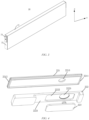


Classifications
-
- H—ELECTRICITY
- H01—ELECTRIC ELEMENTS
- H01M—PROCESSES OR MEANS, e.g. BATTERIES, FOR THE DIRECT CONVERSION OF CHEMICAL ENERGY INTO ELECTRICAL ENERGY
- H01M50/00—Constructional details or processes of manufacture of the non-active parts of electrochemical cells other than fuel cells, e.g. hybrid cells
- H01M50/10—Primary casings; Jackets or wrappings
- H01M50/147—Lids or covers
- H01M50/166—Lids or covers characterised by the methods of assembling casings with lids
- H01M50/169—Lids or covers characterised by the methods of assembling casings with lids by welding, brazing or soldering
-
- H—ELECTRICITY
- H01—ELECTRIC ELEMENTS
- H01M—PROCESSES OR MEANS, e.g. BATTERIES, FOR THE DIRECT CONVERSION OF CHEMICAL ENERGY INTO ELECTRICAL ENERGY
- H01M50/00—Constructional details or processes of manufacture of the non-active parts of electrochemical cells other than fuel cells, e.g. hybrid cells
- H01M50/10—Primary casings; Jackets or wrappings
- H01M50/147—Lids or covers
- H01M50/148—Lids or covers characterised by their shape
-
- H—ELECTRICITY
- H01—ELECTRIC ELEMENTS
- H01M—PROCESSES OR MEANS, e.g. BATTERIES, FOR THE DIRECT CONVERSION OF CHEMICAL ENERGY INTO ELECTRICAL ENERGY
- H01M50/00—Constructional details or processes of manufacture of the non-active parts of electrochemical cells other than fuel cells, e.g. hybrid cells
- H01M50/40—Separators; Membranes; Diaphragms; Spacing elements inside cells
- H01M50/471—Spacing elements inside cells other than separators, membranes or diaphragms; Manufacturing processes thereof
- H01M50/48—Spacing elements inside cells other than separators, membranes or diaphragms; Manufacturing processes thereof characterised by the material
- H01M50/486—Organic material
-
- H—ELECTRICITY
- H01—ELECTRIC ELEMENTS
- H01M—PROCESSES OR MEANS, e.g. BATTERIES, FOR THE DIRECT CONVERSION OF CHEMICAL ENERGY INTO ELECTRICAL ENERGY
- H01M50/00—Constructional details or processes of manufacture of the non-active parts of electrochemical cells other than fuel cells, e.g. hybrid cells
- H01M50/50—Current conducting connections for cells or batteries
- H01M50/543—Terminals
- H01M50/547—Terminals characterised by the disposition of the terminals on the cells
- H01M50/548—Terminals characterised by the disposition of the terminals on the cells on opposite sides of the cell
-
- H—ELECTRICITY
- H01—ELECTRIC ELEMENTS
- H01M—PROCESSES OR MEANS, e.g. BATTERIES, FOR THE DIRECT CONVERSION OF CHEMICAL ENERGY INTO ELECTRICAL ENERGY
- H01M50/00—Constructional details or processes of manufacture of the non-active parts of electrochemical cells other than fuel cells, e.g. hybrid cells
- H01M50/10—Primary casings; Jackets or wrappings
- H01M50/102—Primary casings; Jackets or wrappings characterised by their shape or physical structure
- H01M50/103—Primary casings; Jackets or wrappings characterised by their shape or physical structure prismatic or rectangular
-
- H—ELECTRICITY
- H01—ELECTRIC ELEMENTS
- H01M—PROCESSES OR MEANS, e.g. BATTERIES, FOR THE DIRECT CONVERSION OF CHEMICAL ENERGY INTO ELECTRICAL ENERGY
- H01M50/00—Constructional details or processes of manufacture of the non-active parts of electrochemical cells other than fuel cells, e.g. hybrid cells
- H01M50/10—Primary casings; Jackets or wrappings
- H01M50/147—Lids or covers
- H01M50/148—Lids or covers characterised by their shape
- H01M50/15—Lids or covers characterised by their shape for prismatic or rectangular cells
-
- H—ELECTRICITY
- H01—ELECTRIC ELEMENTS
- H01M—PROCESSES OR MEANS, e.g. BATTERIES, FOR THE DIRECT CONVERSION OF CHEMICAL ENERGY INTO ELECTRICAL ENERGY
- H01M50/00—Constructional details or processes of manufacture of the non-active parts of electrochemical cells other than fuel cells, e.g. hybrid cells
- H01M50/40—Separators; Membranes; Diaphragms; Spacing elements inside cells
- H01M50/471—Spacing elements inside cells other than separators, membranes or diaphragms; Manufacturing processes thereof
- H01M50/477—Spacing elements inside cells other than separators, membranes or diaphragms; Manufacturing processes thereof characterised by their shape
-
- Y—GENERAL TAGGING OF NEW TECHNOLOGICAL DEVELOPMENTS; GENERAL TAGGING OF CROSS-SECTIONAL TECHNOLOGIES SPANNING OVER SEVERAL SECTIONS OF THE IPC; TECHNICAL SUBJECTS COVERED BY FORMER USPC CROSS-REFERENCE ART COLLECTIONS [XRACs] AND DIGESTS
- Y02—TECHNOLOGIES OR APPLICATIONS FOR MITIGATION OR ADAPTATION AGAINST CLIMATE CHANGE
- Y02E—REDUCTION OF GREENHOUSE GAS [GHG] EMISSIONS, RELATED TO ENERGY GENERATION, TRANSMISSION OR DISTRIBUTION
- Y02E60/00—Enabling technologies; Technologies with a potential or indirect contribution to GHG emissions mitigation
- Y02E60/10—Energy storage using batteries
Definitions
- the present application relates to the technical field of batteries, and in particular to a battery cell, a battery and a power consuming device.
- the endurance mileage of electric vehicle is an important factor to their development.
- the energy density of battery needs to be increased.
- the present application provides a battery cell, a battery and a power consuming device, in order to increase the energy density of battery.
- a first aspect of the present application provides a battery cell including a shell and an end cap assembly, the shell being provided with an opening, and the end cap assembly including an end cap, an insulating member and an inner terminal, wherein the end cap is arranged at the opening, and a surface of the end cap close to the shell is provided with an annular protrusion extending in a circumferential direction of the end cap; the annular protrusion shrinks inwards relative to an edge of the end cap to form a flange between an outer side of the annular protrusion and the edge of the end cap, the flange being arranged on a shell wall of the shell, and the annular protrusion extending into the shell; and the insulating member is arranged in a groove enclosed by the annular protrusion, and the inner terminal is arranged on the insulating member.
- the annular protrusion is provided on an inner surface of the end cap to form the groove to avoid taking up the space in cavity, thereby increasing the energy density of the battery cell.
- the flange in a thickness direction of the end cap, includes a melt region close to the shell and a non-melt region away from the shell, the melt region being connected to the shell by means of laser welding.
- the portion of the flange away from the shell forms the non-melt region, so that the distance between a laser welding apparatus and the terminal, which avoids damage to the terminal during welding.
- the melt region has a smaller thickness than the non-melt region.
- the configuration of the non-melt region to have a larger thickness can better avoid damage to the terminal during welding.
- the thickness of the melt region ranges from 0.1 mm to 0.5 mm, and the thickness of the non-melt region ranges from 0.5 mm to 3.5 mm. This configuration can avoid damage to the terminal during laser welding while ensuring the strength of connection between the end cap 221 and the shell.
- an outer wall of the annular protrusion is at least partially attached to an inner wall of the shell.
- the arrangement of the outer wall of the annular protrusion to be at least partially attached to the inner wall of the shell can improve the sealing performance of the inner cavity of the battery cell.
- the arrangement of the outer wall of the annular protrusion to be attached to the inner wall of the shell can prevent laser from entering the shell through the gap between the annular protrusion and the shell and thus causing damage to the electrode assembly.
- the outer wall of the annular protrusion in the thickness direction of the end cap, includes a first section and a second section, the first section being attached to the inner wall of the shell, and the second section being inclined inwards relative to the inner wall of the shell.
- the arrangement of the second section to be inclined inwards can guide the entry of the end cap into the shell, thereby improving the efficiency of entry into the shell.
- the first section includes a welding region close to the flange and a buffer region away from the flange, the welding region being connected to the shell by means of laser welding. In this way, during laser welding, the laser consumes its energy when passing through the gap in the buffer region, which avoids damage to the internal electrode assembly.
- the welding region has a smaller thickness than the buffer region.
- the configuration of the buffer region to have a larger thickness can further prevent laser from entering the inner cavity and thus causing damage to the internal electrode assembly.
- the thickness of the welding region ranges from 0.1 mm to 1.5 mm, and the thickness of the buffer region ranges from 1.5 mm to 3.5 mm. This configuration can avoid taking up excessive space in the inner cavity due to the thickness of the annular protrusion while preventing laser from entering the inner cavity and thus causing damage to the electrode assembly.
- the battery cell further includes an electrode assembly arranged in the shell, the electrode assembly including a main body portion and tabs protruding from the main body portion, the insulating member including a first accommodation recess that is recessed towards a side away from the electrode assembly, and the tabs being arranged in the first accommodation recess and electrically connected to the inner terminal.
- the insulating member further includes a second accommodation recess.
- the second accommodation recess is arranged in a bottom face of the first accommodation recess and recessed towards the side away from the electrode assembly, and the inner terminal is arranged in the second accommodation recess.
- the arrangement of the insulating member to be provided with the first accommodation recess for accommodating the tabs can avoid taking up the space due to the connection of the tabs with the inner terminal, thereby further increasing the energy density of the battery cell.
- the shell includes two openings arranged opposite each other, and the battery cell includes two end cap assemblies corresponding to the two openings.
- the two end cap assemblies are respectively provided with two outer terminals. This may facilitate interconnection of multiple battery cells.
- a second aspect of the present application provides a battery including the battery cell described above.
- a third aspect of the present application provides a power consuming device, which includes the battery cell or battery described above for supplying electric energy.
- the technical terms “first”, “second”, etc. are merely used for distinguishing different objects, and are not to be construed as indicating or implying relative importance or implicitly indicating the number, particular order or primary-secondary relationship of the indicated technical features.
- the phrase “multiple” means two or more, unless otherwise explicitly and specifically defined.
- a and/or B may include: only A exists, both A and B exist, and only B exists.
- the character "/" herein generally indicates an "or" relationship between the associated objects.
- multiple means two or more (including two), similarly the term “multiple groups” means two or more groups (including two groups), and the term “multiple pieces” means two or more pieces (including two pieces).
- the technical terms such as “mount”, “couple”, “connect”, and “fix” should be understood in a broad sense. For example, they may be a fixed connection, a detachable connection, or an integrated connection; may be a mechanical connection or an electric connection; and may be a direct connection, or may be an indirect connection by means of an intermediate medium, or may be communication between interiors of two elements or interaction between the two elements.
- mount may be a fixed connection, a detachable connection, or an integrated connection
- the specific meanings of the foregoing terms in the embodiments of the present application can be understood according to specific circumstances.
- An existing battery cell generally includes a shell, an end cap, and an electrode assembly which is accommodated in the shell.
- the end cap is arranged at the opening of the shell, so that the end cap and the shell enclose together to form a closed cavity to allow the electrode assembly to be arranged in the cavity in a closed manner.
- the inner surface of the end cap includes a protrusion in the thickness direction, and when the end cap is mounted at the opening of the shell, the protrusion extends into the shell to take up part of the space in the cavity and then cause loss of energy density of the battery cell.
- the inventor of the present application has proposed to form a groove in an inner surface of an end cap to avoid taking up the space in the cavity, thereby increasing the energy density of a battery cell.
- a battery cell disclosed in an embodiment of the present application may be used in, but not limited to, vehicles, ships, aircrafts or other power consuming devices. It is possible to use a power system, which is composed of a battery cell, a battery and the like, of the power consuming device disclosed in the present application.
- the embodiments of the present application provide a power consuming device which uses a battery cell and/or a battery as a power source.
- the power consuming device may be, but not limited to, a cell phone, a tablet, a notebook computer, an electric toy, an electric tool, an electric scooter, an electric vehicle, a ship, a spacecraft, etc.
- the electric toy may include a stationary or mobile electric toy, such as a game console, an electric vehicle toy, an electric ship toy and an electric airplane toy.
- the spacecraft may include an airplane, a rocket, a space shuttle, a spaceship, etc.
- FIG. 1 is a schematic diagram of a structure of a vehicle 1000 according to some embodiments of the present application.
- the vehicle 1000 may be a fuel vehicle, a gas vehicle or a new energy vehicle.
- the new energy vehicle may be a battery electric vehicle, a hybrid electric vehicle, an extended-range vehicle, etc.
- a battery 100 is provided inside the vehicle 1000, and the battery 100 may be arranged at the bottom, the front or the back of the vehicle 1000.
- the battery 100 may be configured to supply power to the vehicle 1000.
- the battery 100 may serve as an operating power supply for the vehicle 1000.
- the vehicle 1000 may further include a controller 200 and a motor 300.
- the controller 200 is configured to control the battery 100 to power the motor 300 to meet working power requirements during starting, navigation or traveling of the vehicle 1000, for example.
- the battery 100 may not only serve as an operating power supply for the vehicle 1000, but also serve as a driving power supply for the vehicle 1000, in place of or partially in place of fuel or natural gas, to supply driving power to the vehicle 1000.
- FIG. 2 is an exploded view of a battery 100 according to some embodiments of the present application.
- the battery 100 includes a case 10 and battery cells 20.
- the battery cells 20 are accommodated in the case 10.
- the case 10 is configured to provide an accommodation space for the battery cells 20, and the case 10 may be of various structures.
- the case 10 may include a first portion 11 and a second portion 12, the first portion 11 and the second portion 12 being fitted to each other in a covering manner, and the first portion 11 and the second portion 12 jointly defining the accommodation space for accommodating the battery cells 20.
- the second portion 12 may be of a hollow structure with one end open, the first portion 11 may be of a plate-like structure, and the first portion 11 is fitted to the open side of the second portion 12 in a covering manner, such that the first portion 11 and the second portion 12 jointly define the accommodation space.
- both the first portion 11 and the second portion 12 may be of a hollow structure with one side open, and the open side of the first portion 11 is fitted to the open side of the second portion 12 in a covering manner.
- the case 10 formed by the first portion 11 and the second portion 12 may be in various shapes such as a cylinder and a cuboid.
- multiple battery cells 20 may be provided, and the multiple battery cells 20 may be in series connection, in parallel connection or in series-parallel connection.
- the series-parallel connection means that some of the multiple battery cells 20 are in series connection and some are in parallel connection.
- the multiple battery cells 20 may be directly combined together in series connection, in parallel connection or in series-parallel connection, and then a unit consisting of the multiple battery cells 20 is accommodated in the case 10.
- the battery 100 may also be formed in such a way that multiple battery cells 20 are firstly in series connection, in parallel connection or in series-parallel connection to form a battery module, and then multiple battery modules are in series connection, in parallel connection or in series-parallel connection to form a unit and are accommodated in the case 10.
- the battery 100 may further include other structures.
- the battery 100 may further include a busbar component configured to achieve electrical connection between the multiple battery cells 20.
- the case 10 may be a part of the battery 100, and the case 10 is detachably mounted to the power consuming device.
- the case 10 may also be a space which is formed by a structural member in the power consuming device to accommodate the battery cells 20.
- the case 10 is a space which is formed by a vehicle frame to accommodate the battery cells 20.
- Each battery cell 20 may be a secondary battery or a primary battery; or may be a lithium-sulfur battery, a sodium-ion battery or a magnesium-ion battery, but is not limited thereto.
- the battery cell 20 may be cylindrical, flat, rectangular, or in other shapes.
- FIG. 3 is a schematic perspective view of a structure of a battery cell 20 according to some embodiments of the present application.
- the battery cell 20 includes a shell 21, an end cap assembly 22, an outer terminal 23, an electrode assembly 24 (as shown in FIG. 13 ) and other functional components.
- the electrode assembly 24 is a component of the battery cell 20 where an electrochemical reaction occurs.
- the electrode assembly 24 is mainly formed by winding or stacking a positive electrode plate and a negative electrode plate, and a separator is commonly provided between the positive electrode plate and the negative electrode plate.
- the portions of the positive electrode plate and the negative electrode plate having an active material form a main body portion 241 of the electrode assembly 24, and the portions of the positive electrode plate and the negative electrode plate having no active material respectively form tabs 242.
- a positive active material and a negative active material react with an electrolyte, and the tabs 242 are connected to the terminal to form a current loop.
- the shell 21 is an assembly that creates an internal environment of the battery cell 20 in which the electrode assembly 24, the electrolyte and other components can be accommodated. One or more electrode assemblies 24 can be held in the shell 21.
- the shell 21 may be made of various materials, such as copper, iron, aluminum, stainless steel, an aluminum alloy, and plastic, which will not be specially limited in the embodiments of the present application.
- the end cap assembly 22 refers to a component that is fitted to an opening of the shell 21 in a covering manner to isolate the internal environment of the battery cell 20 from the external environment. Without limitation, the end cap assembly 22 may be shaped to adapt to the shape of the shell 21 to match the shell 21.
- the outer terminal 23 is arranged on the end cap assembly 22 and connected to the inner terminal 223 for electrical connection with the outside.
- the battery cell 20 includes the shell 21 and the end cap assembly 22.
- the shell 21 is provided with an opening.
- the end cap assembly 22 includes an end cap 221, an insulating member 222 and an inner terminal 223.
- the end cap 221 is arranged at the opening, and a surface of the end cap 221 close to the shell 21 is provided with an annular protrusion 2211 extending in a circumferential direction of the end cap 221.
- the annular protrusion 2211 shrinks inwards relative to an edge of the end cap 221 to form a flange 2212 between an outer side of the annular protrusion 2211 and the edge of the end cap 221.
- the flange 2212 is arranged on a shell wall of the shell 21, and the annular protrusion 2211 extends into the shell 21.
- the insulating member 222 is arranged in a groove enclosed by the annular protrusion 2211.
- the inner terminal 223 is arranged on the insulating member 222.
- the shell 21 is a square shell.
- the shell 21 is provided with two openings in communication with each other in a length direction Y, and two end cap assemblies 22 are respectively fitted to the two openings in a covering manner.
- the two end cap assemblies 22 are respectively provided with two outer terminals 23, the two outer terminals 23 are respectively connected to the two inner terminals 223 of the two end cap assemblies 22, and the two inner terminals 223 are respectively connected to a positive tab and a negative tab of the electrode assembly 24.
- the shell 21 may also be provided with only one opening, the end cap assembly 22 is fitted to the opening in a covering manner, and then the end cap assembly 22 is provided with two outer terminals 23 spaced apart from each other.
- the end cap assembly 22 includes an end cap 221, an insulating member 222 and an inner terminal 223.
- a surface of the end cap 221 close to the shell 21 is provided with an annular protrusion 2211 extending in a circumferential direction of the end cap.
- the annular protrusion 2211 shrinks inwards relative to an edge of the end cap 221 to form a flange 2212 between an outer side of the annular protrusion 2211 and the edge of the end cap 221.
- the annular protrusion 2211 shrinks inwards relative to the edge of the end cap 221 in the circumferential direction.
- the interior of the annular protrusion 2211 forms a groove in which the insulating member 222 is arranged to reduce the space to be occupied by the end cap assembly 22.
- the distance between the bottom face of the groove formed by the annular protrusion 2211 and the outer surface of the end cap 221 is greater than the distance between the end face of the flange 2212 and the outer surface of the end cap 221. That is to say, although the groove is formed in the inner surface of the end cap 221, the bottom face of the groove and the end face of the flange 2212 are not coplanar, which ensures the strength of the end cap 221.
- the end cap 221 is shaped to adapt to the shape of the opening of the shell 21, and in this embodiment, the opening of the shell 21 is square, and then the end cap 221 is also square.
- the annular protrusion 2211 is also square.
- the end cap 221 may be made of a material (e.g., an aluminum alloy) with a certain hardness and strength. In this way, the end cap 221 is less likely to deform when being pressed or collided, so that the battery cell 20 can have higher structural strength and then have improved safety performance.
- the end cap 221 may be further provided with a pressure relief mechanism that is configured to release the internal pressure when the internal pressure or temperature of the battery cell 20 reaches a threshold.
- the end cap 221 may also be made of various materials, such as copper, iron, aluminum, stainless steel, an aluminum alloy, and plastic, which will not be specially limited in the embodiments of the present application.
- the insulating member 222 may be configured to isolate electrical connection components in the shell 21 from the end cap 221 to reduce the risk of short circuit.
- the insulating member may be made of plastic, rubber, etc.
- the flange 2212 of the end cap 221 abuts against the shell wall of the shell 21, the annular protrusion 2211 extends into the shell 21, and the flange 2212 and the annular protrusion 2211 are both connected to the shell 21 to achieve connection between the end cap 221 and the shell 21.
- the inner surface of the end cap 221 is provided with the annular protrusion to form the groove, which reduces the occupied space of the internal cavity of the shell 21, thereby increasing the energy density of the battery cell 20.
- the annular protrusion 2211 can still be connected to the shell wall of the shell 21 to ensure the strength of connection between the end cap 221 and the shell 21.
- the outer wall of the annular protrusion 2211 is at least partially attached to the inner wall of the shell 21.
- the outer wall of the annular protrusion 2211 is at least partially attached to the inner wall of the shell 21.
- the end cap 221 is connected to the shell 21 by means of laser welding, in the melt portion R as shown in FIG. 12 , it can be seen that the portion of the annular protrusion 2211 close to the flange 221 is melted and connected to the inner wall of the shell 21.
- the arrangement of the outer wall of the annular protrusion 2211 to be at least partially attached to the inner wall of the shell 21 can improve the sealing performance of the inner cavity of the battery cell 20. Moreover, the arrangement of the outer wall of the annular protrusion 2211 to be attached to the inner wall of the shell 21 can prevent laser from entering the shell 21 through the gap between the annular protrusion 2211 and the shell 21 and thus causing damage to the electrode assembly 24.
- the outer wall of the annular protrusion 2211 in the thickness direction of the end cap 221, includes a first section 2211A and a second section 2211B, the first section 2211A being attached to the inner wall of the shell 21, and the second section 2211B being inclined inwards relative to the inner wall of the shell 21.
- the arrangement of the second section 2211B to be inclined inwards may guide the entry of the end cap 221 into the shell, thereby improving the efficiency of entry into the shell.
- the distance G between an end portion of the second section 2211B and the inner wall of the shell 21 is in the range of 1 mm ⁇ G1 ⁇ the width P of the annular protrusion 2211.
- the arrangement of the second section 2211B to be inclined inwards may guide the entry of the end cap 221 into the shell, thereby improving the efficiency of entry into the shell.
- the battery cell 20 further includes an electrode assembly 24 arranged in shell 21.
- the electrode assembly 24 includes a main body portion 241 and tabs 242 extending from the main body portion 241.
- the insulating member 222 includes a first accommodation recess 2221 recessed towards the side away from the electrode assembly 24.
- the tabs 242 are arranged in the first accommodation recess 2221 and electrically connected to the inner terminal 223.
- the arrangement of the insulating member 222 to be provided with the first accommodation recess 2221 for accommodating the tabs 242 can avoid taking up the space due to the connection of the tabs 242 with the inner terminal 223, thereby further increasing the energy density of the battery cell 20.
- the insulating member 222 further includes a second accommodation recess 2222 that is arranged on the bottom face of the first accommodation recess 2221 and recessed towards the side away from the electrode assembly 24, and the inner terminal 223 is arranged in the second accommodation recess 2222.
- the second accommodation recess 2222 is recessed, relative to the bottom face of the first accommodation recess 2221, towards the side away from the electrode assembly 24. As shown in FIG. 6 , after the inner terminal 223 is placed in the second accommodation recess 2222, the surface of the inner terminal 223 is flush with the bottom face of the first accommodation recess 2221. In this way, the inner terminal 223 does not need to take up excessive space.
- the end cap 221 is provided with a first terminal hole 2213
- the insulating member 222 is provided with a second terminal hole 2223 coaxially arranged with the first terminal hole 2213
- the inner terminal 223 sequentially passes through the second terminal hole 2223 and the first terminal hole 2213 and is then connected to the outer terminal 23.
- the terminals include the inner terminal 223 and the outer terminal 23.
- the terminals are offset to one side relative to the center of the battery cell 20. This arrangement facilitates reduction of the length of an adapter plate when the tabs 242 of the electrode assembly 24 extend from one side in the height direction Z and need to be connected to the inner terminal 223 by means of the adapter plate.
- the arrangement of the terminals to be offset to one side facilitates the arrangement of an explosion-proof valve and other components on the end cap 221.
- the flange 2212 in the thickness direction of the end cap 221, includes a melt region T1 close to the shell 21 and a non-melt region T2 away from the shell 21, the melt region T1 being connected to the shell 21 by means of laser welding.
- the melt region T1 of the flange 2212 close to the shell 21 is melted under the laser action and then connected to the shell 21, and the portion of the flange 2212 away from the shell 21 forms a non-melt region T2, so that the distance between a laser welding apparatus and the terminal is increased, which avoids damage to the terminal during welding.
- the melt region T1 has a smaller thickness than the non-melt region T2.
- the configuration of the non-melt region T2 to have a larger thickness can better avoid damage to the terminal during welding.
- the thickness of the melt region T1 ranges from 0.1 mm to 0.5 mm, and the thickness of the non-melt region T2 ranges from 0.5 mm to 3.5 mm. This thickness configuration can avoid damage to the terminal during laser welding while ensuring the strength of connection between the end cap 221 and the shell 21.
- the first section 2211A of the annular protrusion 2211 includes a welding region H1 close to the flange 2212 and a buffer region H2 away from the flange 2212, the welding region H1 being connected to the shell 21 by means of laser welding. As shown in FIG. 12 , in this way, during laser welding, even if the annular protrusion 2211 is not completely attached to the shell 21, laser can consume its energy when passing through the gap in the buffer region H2, which avoids damage to the internal electrode assembly 24.
- this configuration increases the thickness of the annular protrusion 2211 and then increases the clamping area during assembly, thereby improving the assembly efficiency.
- the annular protrusion 2211 has an increased thickness, the end portion of the second section 2211B close to the first section 2211A can be further arranged towards one side of the first section 2211A, so that the area of the gap between the second section 2211B and the inner wall of the shell 21 is increased, thereby further improving the efficiency of entry into the shell.
- the welding region H1 has a smaller thickness than the buffer region H2.
- the configuration of the buffer region H2 to have a larger thickness can prevent laser from entering the inner cavity and thus causing damage to the internal electrode assembly.
- the thickness of the welding region H1 ranges from 0.1 mm to 1.5 mm, and the thickness of the buffer region H2 ranges from 1.5 mm to 3.5 mm. This configuration can prevent laser from entering the inner cavity and thus causing damage to the electrode assembly 24, and avoid taking up excessive space in the inner cavity due to the thickness of the annular protrusion 2211.
- the shell 21 includes two openings arranged opposite each other, and the battery cell 20 includes two end cap assemblies 22 corresponding to the two openings.
- the two end cap assemblies 22 are respectively provided with two outer terminals 23. This may facilitate interconnection of multiple battery cells 20.
- the present application provides a battery 100 including the battery cell 20 described above.
- the present application further provides a power consuming device, which includes the battery cell 20 and/or the battery 100 described above for supplying electric energy.
Landscapes
- Chemical & Material Sciences (AREA)
- Chemical Kinetics & Catalysis (AREA)
- Electrochemistry (AREA)
- General Chemical & Material Sciences (AREA)
- Sealing Battery Cases Or Jackets (AREA)
- Battery Mounting, Suspending (AREA)
Abstract
Description
- The present application is based on and claims priority to
Chinese patent application No. 202220226628.3 filed on January 27, 2022 - The present application relates to the technical field of batteries, and in particular to a battery cell, a battery and a power consuming device.
- Achieving energy conservation and emission reduction is the key to the sustainable development of automotive industry. Electric vehicles have become an important part of the sustainable development of the automotive industry due to their advantages in energy conservation and environmental protection.
- For the electric vehicles, the endurance mileage of electric vehicle is an important factor to their development. In order to increase the endurance mileage of electric vehicle, the energy density of battery needs to be increased.
- In view of the problem described above, the present application provides a battery cell, a battery and a power consuming device, in order to increase the energy density of battery.
- A first aspect of the present application provides a battery cell including a shell and an end cap assembly, the shell being provided with an opening, and the end cap assembly including an end cap, an insulating member and an inner terminal, wherein the end cap is arranged at the opening, and a surface of the end cap close to the shell is provided with an annular protrusion extending in a circumferential direction of the end cap; the annular protrusion shrinks inwards relative to an edge of the end cap to form a flange between an outer side of the annular protrusion and the edge of the end cap, the flange being arranged on a shell wall of the shell, and the annular protrusion extending into the shell; and the insulating member is arranged in a groove enclosed by the annular protrusion, and the inner terminal is arranged on the insulating member.
- In the technical solution of the present application, in the battery cell, the annular protrusion is provided on an inner surface of the end cap to form the groove to avoid taking up the space in cavity, thereby increasing the energy density of the battery cell.
- In some embodiments, in a thickness direction of the end cap, the flange includes a melt region close to the shell and a non-melt region away from the shell, the melt region being connected to the shell by means of laser welding. The portion of the flange away from the shell forms the non-melt region, so that the distance between a laser welding apparatus and the terminal, which avoids damage to the terminal during welding.
- In some embodiments, the melt region has a smaller thickness than the non-melt region. The configuration of the non-melt region to have a larger thickness can better avoid damage to the terminal during welding.
- In some embodiments, the thickness of the melt region ranges from 0.1 mm to 0.5 mm, and the thickness of the non-melt region ranges from 0.5 mm to 3.5 mm. This configuration can avoid damage to the terminal during laser welding while ensuring the strength of connection between the
end cap 221 and the shell. - In some embodiments, an outer wall of the annular protrusion is at least partially attached to an inner wall of the shell. The arrangement of the outer wall of the annular protrusion to be at least partially attached to the inner wall of the shell can improve the sealing performance of the inner cavity of the battery cell. Moreover, the arrangement of the outer wall of the annular protrusion to be attached to the inner wall of the shell can prevent laser from entering the shell through the gap between the annular protrusion and the shell and thus causing damage to the electrode assembly.
- In some embodiments, in the thickness direction of the end cap, the outer wall of the annular protrusion includes a first section and a second section, the first section being attached to the inner wall of the shell, and the second section being inclined inwards relative to the inner wall of the shell. During assembly of the end cap, since the second section firstly enters the shell, the arrangement of the second section to be inclined inwards can guide the entry of the end cap into the shell, thereby improving the efficiency of entry into the shell.
- In some embodiments, the first section includes a welding region close to the flange and a buffer region away from the flange, the welding region being connected to the shell by means of laser welding. In this way, during laser welding, the laser consumes its energy when passing through the gap in the buffer region, which avoids damage to the internal electrode assembly.
- In some embodiments, the welding region has a smaller thickness than the buffer region. The configuration of the buffer region to have a larger thickness can further prevent laser from entering the inner cavity and thus causing damage to the internal electrode assembly.
- In some embodiments, the thickness of the welding region ranges from 0.1 mm to 1.5 mm, and the thickness of the buffer region ranges from 1.5 mm to 3.5 mm. This configuration can avoid taking up excessive space in the inner cavity due to the thickness of the annular protrusion while preventing laser from entering the inner cavity and thus causing damage to the electrode assembly.
- In some embodiments, the battery cell further includes an electrode assembly arranged in the shell, the electrode assembly including a main body portion and tabs protruding from the main body portion, the insulating member including a first accommodation recess that is recessed towards a side away from the electrode assembly, and the tabs being arranged in the first accommodation recess and electrically connected to the inner terminal.
- In some embodiments, the insulating member further includes a second accommodation recess. The second accommodation recess is arranged in a bottom face of the first accommodation recess and recessed towards the side away from the electrode assembly, and the inner terminal is arranged in the second accommodation recess. The arrangement of the insulating member to be provided with the first accommodation recess for accommodating the tabs can avoid taking up the space due to the connection of the tabs with the inner terminal, thereby further increasing the energy density of the battery cell.
- In some embodiments, the shell includes two openings arranged opposite each other, and the battery cell includes two end cap assemblies corresponding to the two openings. The two end cap assemblies are respectively provided with two outer terminals. This may facilitate interconnection of multiple battery cells.
- A second aspect of the present application provides a battery including the battery cell described above.
- A third aspect of the present application provides a power consuming device, which includes the battery cell or battery described above for supplying electric energy.
- The aforementioned description is merely an overview of the technical solutions of the present application. To understand the technical means of the present application more clearly to implement the technical solutions according to the content of the specification, and to make the above and other objectives, features and advantages of the present application more readily understandable, the detailed description of embodiments of the present application will be specifically described below.
- To describe the technical solutions of the embodiments of the present application more clearly, the drawings required in the embodiments of the present application will be illustrated briefly below. Obviously, the drawings illustrated below merely show some embodiments of the present application, and for those of ordinary skill in the art, other drawings can be obtained on the basis of these drawings without any creative efforts.
-
FIG. 1 is a schematic diagram of a structure of a vehicle according to some embodiments of the present application; -
FIG. 2 is a schematic exploded view of a structure of a battery according to some embodiments of the present application; -
FIG. 3 is a schematic perspective view of a structure of a battery cell according to some embodiments of the present application; -
FIG. 4 is a schematic exploded view of a structure of an end cap assembly of a battery cell according to some embodiments of the present application; -
FIG. 5 is a front view of an end cap assembly according to some embodiments of the present application; -
FIG. 6 is a cross-sectional view along line A-A of the end cap assembly shown inFIG. 5 ; -
FIG. 7 is a schematic partial enlarged view of a structure of part M inFIG. 6 ; -
FIG. 8 is a side view of an end cap assembly according to some embodiments of the present application; -
FIG. 9 is a front view of a battery cell according to some embodiments of the present application; -
FIG. 10 is a cross-sectional view along line B-B of the battery cell shown inFIG. 9 ; -
FIG. 11 is a schematic partial enlarged view of a structure of part N inFIG. 10 ; -
FIG. 12 is a schematic diagram of welding of the end cap assembly shown inFIG. 11 ; and -
FIG. 13 is a schematic diagram of a structure of some embodiments of an electrode assembly in a battery cell. - In the drawings, the figures are not drawn to scale.
-
- 1000. vehicle;
- 100. battery; 200. controller; 300. motor;
- 10. case; 11. first portion; 12. second portion;
- 20. battery cell; 21. shell; 22. end cap assembly; 221. end cap; 2211. annular protrusion; 2211A. first section; 2211B. second section; 2212. flange; 2213. first terminal hole; 222. insulating member; 2221. first accommodation recess; 2222. second accommodation recess; 2223. second terminal hole; 223. inner terminal; 23. outer terminal; 24. electrode assembly; 241. main body portion; 242. tab.
- Unless otherwise defined, all technical and scientific terms used herein have the same meanings as those commonly understood by those skilled in the art to which the present application belongs. The terms used herein are merely for the purpose of describing specific embodiments, but are not intended to limit the present application. The terms "include/comprise" and "has/have" and any variations thereof in the specification and the claims of the present application and in the foregoing brief description of the drawings are intended to cover non-exclusive inclusions.
- In the description of the embodiments of the present application, the technical terms "first", "second", etc. are merely used for distinguishing different objects, and are not to be construed as indicating or implying relative importance or implicitly indicating the number, particular order or primary-secondary relationship of the indicated technical features. In the description of the embodiments of the present application, the phrase "multiple" means two or more, unless otherwise explicitly and specifically defined.
- The phrase "embodiment" mentioned herein means that the specific features, structures or characteristics described with reference to the embodiment can be encompassed in at least one embodiment of the present application. The phrase at various locations in the specification does not necessarily refer to the same embodiment, or an independent or alternative embodiment exclusive of other embodiments. Those skilled in the art understand explicitly or implicitly that the embodiments described herein may be combined with other embodiments.
- In the description of the embodiments of the present application, the term "and/or" is merely intended to describe the associated relationship of associated objects, indicating that three relationships may exist. For example, A and/or B may include: only A exists, both A and B exist, and only B exists. In addition, the character "/" herein generally indicates an "or" relationship between the associated objects.
- In the description of the embodiments of the present application, the term "multiple" means two or more (including two), similarly the term "multiple groups" means two or more groups (including two groups), and the term "multiple pieces" means two or more pieces (including two pieces).
- In the description of the embodiments of the present application, the orientation or position relationship indicated by the technical terms "central", "longitudinal", "transverse", "length", "width", "thickness", "upper", "lower", "front"; "rear", "left", "right", "vertical", "horizontal", "top", "bottom", "inner", "outer", "clockwise", "counterclockwise", "axial", "radial", "circumferential", etc. are based on the orientation or position relationship shown in the drawings and are merely intended to facilitate and simplify the description of the embodiments of the present application, rather than indicating or implying that the device or element referred to must have a particular orientation or be constructed and operated in a particular orientation, and therefore not to be construed as limiting the embodiments of the present application.
- In the description of the embodiments of the present application, unless otherwise explicitly specified and defined, the technical terms such as "mount", "couple", "connect", and "fix" should be understood in a broad sense. For example, they may be a fixed connection, a detachable connection, or an integrated connection; may be a mechanical connection or an electric connection; and may be a direct connection, or may be an indirect connection by means of an intermediate medium, or may be communication between interiors of two elements or interaction between the two elements. For those of ordinary skill in the art, the specific meanings of the foregoing terms in the embodiments of the present application can be understood according to specific circumstances.
- An existing battery cell generally includes a shell, an end cap, and an electrode assembly which is accommodated in the shell. The end cap is arranged at the opening of the shell, so that the end cap and the shell enclose together to form a closed cavity to allow the electrode assembly to be arranged in the cavity in a closed manner. In the related art known to the inventor, the inner surface of the end cap includes a protrusion in the thickness direction, and when the end cap is mounted at the opening of the shell, the protrusion extends into the shell to take up part of the space in the cavity and then cause loss of energy density of the battery cell.
- To solve the problem described above, the inventor of the present application has proposed to form a groove in an inner surface of an end cap to avoid taking up the space in the cavity, thereby increasing the energy density of a battery cell.
- A battery cell disclosed in an embodiment of the present application may be used in, but not limited to, vehicles, ships, aircrafts or other power consuming devices. It is possible to use a power system, which is composed of a battery cell, a battery and the like, of the power consuming device disclosed in the present application.
- The embodiments of the present application provide a power consuming device which uses a battery cell and/or a battery as a power source. The power consuming device may be, but not limited to, a cell phone, a tablet, a notebook computer, an electric toy, an electric tool, an electric scooter, an electric vehicle, a ship, a spacecraft, etc. The electric toy may include a stationary or mobile electric toy, such as a game console, an electric vehicle toy, an electric ship toy and an electric airplane toy. The spacecraft may include an airplane, a rocket, a space shuttle, a spaceship, etc.
- For ease of description of the following embodiments, an example in which a power consuming device according to an embodiment of the present application is a
vehicle 1000 is taken for description. - Referring to
FIG. 1, FIG. 1 is a schematic diagram of a structure of avehicle 1000 according to some embodiments of the present application. Thevehicle 1000 may be a fuel vehicle, a gas vehicle or a new energy vehicle. The new energy vehicle may be a battery electric vehicle, a hybrid electric vehicle, an extended-range vehicle, etc. Abattery 100 is provided inside thevehicle 1000, and thebattery 100 may be arranged at the bottom, the front or the back of thevehicle 1000. Thebattery 100 may be configured to supply power to thevehicle 1000. For example, thebattery 100 may serve as an operating power supply for thevehicle 1000. Thevehicle 1000 may further include acontroller 200 and amotor 300. Thecontroller 200 is configured to control thebattery 100 to power themotor 300 to meet working power requirements during starting, navigation or traveling of thevehicle 1000, for example. - In some embodiments of the present application, the
battery 100 may not only serve as an operating power supply for thevehicle 1000, but also serve as a driving power supply for thevehicle 1000, in place of or partially in place of fuel or natural gas, to supply driving power to thevehicle 1000. - Referring to
FIG. 2, FIG. 2 is an exploded view of abattery 100 according to some embodiments of the present application. Thebattery 100 includes a case 10 andbattery cells 20. Thebattery cells 20 are accommodated in the case 10. The case 10 is configured to provide an accommodation space for thebattery cells 20, and the case 10 may be of various structures. In some embodiments, the case 10 may include a first portion 11 and asecond portion 12, the first portion 11 and thesecond portion 12 being fitted to each other in a covering manner, and the first portion 11 and thesecond portion 12 jointly defining the accommodation space for accommodating thebattery cells 20. Thesecond portion 12 may be of a hollow structure with one end open, the first portion 11 may be of a plate-like structure, and the first portion 11 is fitted to the open side of thesecond portion 12 in a covering manner, such that the first portion 11 and thesecond portion 12 jointly define the accommodation space. Alternatively, both the first portion 11 and thesecond portion 12 may be of a hollow structure with one side open, and the open side of the first portion 11 is fitted to the open side of thesecond portion 12 in a covering manner. Of course, the case 10 formed by the first portion 11 and thesecond portion 12 may be in various shapes such as a cylinder and a cuboid. - In the
battery 100,multiple battery cells 20 may be provided, and themultiple battery cells 20 may be in series connection, in parallel connection or in series-parallel connection. The series-parallel connection means that some of themultiple battery cells 20 are in series connection and some are in parallel connection. Themultiple battery cells 20 may be directly combined together in series connection, in parallel connection or in series-parallel connection, and then a unit consisting of themultiple battery cells 20 is accommodated in the case 10. Of course, thebattery 100 may also be formed in such a way thatmultiple battery cells 20 are firstly in series connection, in parallel connection or in series-parallel connection to form a battery module, and then multiple battery modules are in series connection, in parallel connection or in series-parallel connection to form a unit and are accommodated in the case 10. Thebattery 100 may further include other structures. For example, thebattery 100 may further include a busbar component configured to achieve electrical connection between themultiple battery cells 20. - The case 10 may be a part of the
battery 100, and the case 10 is detachably mounted to the power consuming device. Alternatively, the case 10 may also be a space which is formed by a structural member in the power consuming device to accommodate thebattery cells 20. For example, when thebattery cells 20 is used in thevehicle 1000, the case 10 is a space which is formed by a vehicle frame to accommodate thebattery cells 20. - Each
battery cell 20 may be a secondary battery or a primary battery; or may be a lithium-sulfur battery, a sodium-ion battery or a magnesium-ion battery, but is not limited thereto. Thebattery cell 20 may be cylindrical, flat, rectangular, or in other shapes. - Referring to
FIG. 3, FIG. 3 is a schematic perspective view of a structure of abattery cell 20 according to some embodiments of the present application. As shown inFIG. 3 , thebattery cell 20 includes ashell 21, anend cap assembly 22, anouter terminal 23, an electrode assembly 24 (as shown inFIG. 13 ) and other functional components. - The
electrode assembly 24 is a component of thebattery cell 20 where an electrochemical reaction occurs. Theelectrode assembly 24 is mainly formed by winding or stacking a positive electrode plate and a negative electrode plate, and a separator is commonly provided between the positive electrode plate and the negative electrode plate. The portions of the positive electrode plate and the negative electrode plate having an active material form amain body portion 241 of theelectrode assembly 24, and the portions of the positive electrode plate and the negative electrode plate having no active material respectively formtabs 242. During the charging and discharging of thebattery 100, a positive active material and a negative active material react with an electrolyte, and thetabs 242 are connected to the terminal to form a current loop. - The
shell 21 is an assembly that creates an internal environment of thebattery cell 20 in which theelectrode assembly 24, the electrolyte and other components can be accommodated. One ormore electrode assemblies 24 can be held in theshell 21. Theshell 21 may be made of various materials, such as copper, iron, aluminum, stainless steel, an aluminum alloy, and plastic, which will not be specially limited in the embodiments of the present application. - The
end cap assembly 22 refers to a component that is fitted to an opening of theshell 21 in a covering manner to isolate the internal environment of thebattery cell 20 from the external environment. Without limitation, theend cap assembly 22 may be shaped to adapt to the shape of theshell 21 to match theshell 21. - As shown in
FIG. 4 , theouter terminal 23 is arranged on theend cap assembly 22 and connected to theinner terminal 223 for electrical connection with the outside. - Referring to
FIGS. 3 to 8 , thebattery cell 20 includes theshell 21 and theend cap assembly 22. Theshell 21 is provided with an opening. Theend cap assembly 22 includes anend cap 221, an insulatingmember 222 and aninner terminal 223. Theend cap 221 is arranged at the opening, and a surface of theend cap 221 close to theshell 21 is provided with anannular protrusion 2211 extending in a circumferential direction of theend cap 221. Theannular protrusion 2211 shrinks inwards relative to an edge of theend cap 221 to form aflange 2212 between an outer side of theannular protrusion 2211 and the edge of theend cap 221. Theflange 2212 is arranged on a shell wall of theshell 21, and theannular protrusion 2211 extends into theshell 21. The insulatingmember 222 is arranged in a groove enclosed by theannular protrusion 2211. Theinner terminal 223 is arranged on the insulatingmember 222. - As shown in
FIG 3 , theshell 21 is a square shell. Theshell 21 is provided with two openings in communication with each other in a length direction Y, and twoend cap assemblies 22 are respectively fitted to the two openings in a covering manner. The twoend cap assemblies 22 are respectively provided with twoouter terminals 23, the twoouter terminals 23 are respectively connected to the twoinner terminals 223 of the twoend cap assemblies 22, and the twoinner terminals 223 are respectively connected to a positive tab and a negative tab of theelectrode assembly 24. In other embodiments not shown in the figure, theshell 21 may also be provided with only one opening, theend cap assembly 22 is fitted to the opening in a covering manner, and then theend cap assembly 22 is provided with twoouter terminals 23 spaced apart from each other. - As shown in
FIG. 4 , theend cap assembly 22 includes anend cap 221, an insulatingmember 222 and aninner terminal 223. A surface of theend cap 221 close to theshell 21 is provided with anannular protrusion 2211 extending in a circumferential direction of the end cap. Theannular protrusion 2211 shrinks inwards relative to an edge of theend cap 221 to form aflange 2212 between an outer side of theannular protrusion 2211 and the edge of theend cap 221. Here, theannular protrusion 2211 shrinks inwards relative to the edge of theend cap 221 in the circumferential direction. In this way, the interior of theannular protrusion 2211 forms a groove in which the insulatingmember 222 is arranged to reduce the space to be occupied by theend cap assembly 22. Referring toFIGS. 11 and12 , the distance between the bottom face of the groove formed by theannular protrusion 2211 and the outer surface of theend cap 221 is greater than the distance between the end face of theflange 2212 and the outer surface of theend cap 221. That is to say, although the groove is formed in the inner surface of theend cap 221, the bottom face of the groove and the end face of theflange 2212 are not coplanar, which ensures the strength of theend cap 221. - The
end cap 221 is shaped to adapt to the shape of the opening of theshell 21, and in this embodiment, the opening of theshell 21 is square, and then theend cap 221 is also square. Correspondingly, theannular protrusion 2211 is also square. In other embodiments not shown in the figure, since theshell 21 is cylindrical, theend cap 221 is round, and theannular protrusion 2211 is also round. Optionally, theend cap 221 may be made of a material (e.g., an aluminum alloy) with a certain hardness and strength. In this way, theend cap 221 is less likely to deform when being pressed or collided, so that thebattery cell 20 can have higher structural strength and then have improved safety performance. In some embodiments, theend cap 221 may be further provided with a pressure relief mechanism that is configured to release the internal pressure when the internal pressure or temperature of thebattery cell 20 reaches a threshold. Theend cap 221 may also be made of various materials, such as copper, iron, aluminum, stainless steel, an aluminum alloy, and plastic, which will not be specially limited in the embodiments of the present application. The insulatingmember 222 may be configured to isolate electrical connection components in theshell 21 from theend cap 221 to reduce the risk of short circuit. For example, the insulating member may be made of plastic, rubber, etc. - During assembly of the
battery cell 20 of the embodiments of the present application, theflange 2212 of theend cap 221 abuts against the shell wall of theshell 21, theannular protrusion 2211 extends into theshell 21, and theflange 2212 and theannular protrusion 2211 are both connected to theshell 21 to achieve connection between theend cap 221 and theshell 21. In thebattery cell 20 of the embodiments of the present application, the inner surface of theend cap 221 is provided with the annular protrusion to form the groove, which reduces the occupied space of the internal cavity of theshell 21, thereby increasing the energy density of thebattery cell 20. Moreover, theannular protrusion 2211 can still be connected to the shell wall of theshell 21 to ensure the strength of connection between theend cap 221 and theshell 21. - In some embodiments, referring to
FIGS. 9 to 11 , the outer wall of theannular protrusion 2211 is at least partially attached to the inner wall of theshell 21. - As shown in
FIG. 12 , the outer wall of theannular protrusion 2211 is at least partially attached to the inner wall of theshell 21. When theend cap 221 is connected to theshell 21 by means of laser welding, in the melt portion R as shown inFIG. 12 , it can be seen that the portion of theannular protrusion 2211 close to theflange 221 is melted and connected to the inner wall of theshell 21. - The arrangement of the outer wall of the
annular protrusion 2211 to be at least partially attached to the inner wall of theshell 21 can improve the sealing performance of the inner cavity of thebattery cell 20. Moreover, the arrangement of the outer wall of theannular protrusion 2211 to be attached to the inner wall of theshell 21 can prevent laser from entering theshell 21 through the gap between theannular protrusion 2211 and theshell 21 and thus causing damage to theelectrode assembly 24. - In some embodiments, in the thickness direction of the
end cap 221, the outer wall of theannular protrusion 2211 includes afirst section 2211A and asecond section 2211B, thefirst section 2211A being attached to the inner wall of theshell 21, and thesecond section 2211B being inclined inwards relative to the inner wall of theshell 21. - As shown in
FIG. 11 , during assembly of theend cap 221, since thesecond section 2211B firstly enters theshell 21, the arrangement of thesecond section 2211B to be inclined inwards may guide the entry of theend cap 221 into the shell, thereby improving the efficiency of entry into the shell. Specifically, the distance G between an end portion of thesecond section 2211B and the inner wall of theshell 21 is in the range of 1 mm ≤ G1 ≤ the width P of theannular protrusion 2211. - The arrangement of the
second section 2211B to be inclined inwards may guide the entry of theend cap 221 into the shell, thereby improving the efficiency of entry into the shell. - In some embodiments, as shown in
FIG. 13 , thebattery cell 20 further includes anelectrode assembly 24 arranged inshell 21. Theelectrode assembly 24 includes amain body portion 241 andtabs 242 extending from themain body portion 241. As shown inFIG. 4 , the insulatingmember 222 includes afirst accommodation recess 2221 recessed towards the side away from theelectrode assembly 24. Thetabs 242 are arranged in thefirst accommodation recess 2221 and electrically connected to theinner terminal 223. - The arrangement of the insulating
member 222 to be provided with thefirst accommodation recess 2221 for accommodating thetabs 242 can avoid taking up the space due to the connection of thetabs 242 with theinner terminal 223, thereby further increasing the energy density of thebattery cell 20. - In some embodiments, the insulating
member 222 further includes asecond accommodation recess 2222 that is arranged on the bottom face of thefirst accommodation recess 2221 and recessed towards the side away from theelectrode assembly 24, and theinner terminal 223 is arranged in thesecond accommodation recess 2222. - The
second accommodation recess 2222 is recessed, relative to the bottom face of thefirst accommodation recess 2221, towards the side away from theelectrode assembly 24. As shown inFIG. 6 , after theinner terminal 223 is placed in thesecond accommodation recess 2222, the surface of theinner terminal 223 is flush with the bottom face of thefirst accommodation recess 2221. In this way, theinner terminal 223 does not need to take up excessive space. - As shown in
FIG. 4 , theend cap 221 is provided with a firstterminal hole 2213, the insulatingmember 222 is provided with a secondterminal hole 2223 coaxially arranged with the firstterminal hole 2213, and theinner terminal 223 sequentially passes through the secondterminal hole 2223 and the firstterminal hole 2213 and is then connected to theouter terminal 23. In this embodiment, the terminals include theinner terminal 223 and theouter terminal 23. In a height direction Z, the terminals are offset to one side relative to the center of thebattery cell 20. This arrangement facilitates reduction of the length of an adapter plate when thetabs 242 of theelectrode assembly 24 extend from one side in the height direction Z and need to be connected to theinner terminal 223 by means of the adapter plate. Moreover, the arrangement of the terminals to be offset to one side facilitates the arrangement of an explosion-proof valve and other components on theend cap 221. - The inventor has found in his research that the arrangement of the terminals to be offset may cause the terminals to be positioned close to the edge of the
end cap 221, which may cause damage to the terminals during welding of theend cap 221 and theshell 21. To address this issue, referring toFIGS. 11 and12 , in some embodiments, in the thickness direction of theend cap 221, theflange 2212 includes a melt region T1 close to theshell 21 and a non-melt region T2 away from theshell 21, the melt region T1 being connected to theshell 21 by means of laser welding. That is to say, since theflange 2212 has an increased thickness, the melt region T1 of theflange 2212 close to theshell 21 is melted under the laser action and then connected to theshell 21, and the portion of theflange 2212 away from theshell 21 forms a non-melt region T2, so that the distance between a laser welding apparatus and the terminal is increased, which avoids damage to the terminal during welding. - In some embodiments, the melt region T1 has a smaller thickness than the non-melt region T2. The configuration of the non-melt region T2 to have a larger thickness can better avoid damage to the terminal during welding.
- In some embodiments, the thickness of the melt region T1 ranges from 0.1 mm to 0.5 mm, and the thickness of the non-melt region T2 ranges from 0.5 mm to 3.5 mm. This thickness configuration can avoid damage to the terminal during laser welding while ensuring the strength of connection between the
end cap 221 and theshell 21. - To prevent laser from entering the
shell 21 through the gap between theannular protrusions 2211 and the inner wall of theshell 21 during welding and thus causing damage to theinternal electrode assembly 24, in some embodiments, thefirst section 2211A of theannular protrusion 2211 includes a welding region H1 close to theflange 2212 and a buffer region H2 away from theflange 2212, the welding region H1 being connected to theshell 21 by means of laser welding. As shown inFIG. 12 , in this way, during laser welding, even if theannular protrusion 2211 is not completely attached to theshell 21, laser can consume its energy when passing through the gap in the buffer region H2, which avoids damage to theinternal electrode assembly 24. Moreover, this configuration increases the thickness of theannular protrusion 2211 and then increases the clamping area during assembly, thereby improving the assembly efficiency. Moreover, since theannular protrusion 2211 has an increased thickness, the end portion of thesecond section 2211B close to thefirst section 2211A can be further arranged towards one side of thefirst section 2211A, so that the area of the gap between thesecond section 2211B and the inner wall of theshell 21 is increased, thereby further improving the efficiency of entry into the shell. - In some embodiments, the welding region H1 has a smaller thickness than the buffer region H2. The configuration of the buffer region H2 to have a larger thickness can prevent laser from entering the inner cavity and thus causing damage to the internal electrode assembly.
- In some embodiments, the thickness of the welding region H1 ranges from 0.1 mm to 1.5 mm, and the thickness of the buffer region H2 ranges from 1.5 mm to 3.5 mm. This configuration can prevent laser from entering the inner cavity and thus causing damage to the
electrode assembly 24, and avoid taking up excessive space in the inner cavity due to the thickness of theannular protrusion 2211. - In some embodiments, the
shell 21 includes two openings arranged opposite each other, and thebattery cell 20 includes twoend cap assemblies 22 corresponding to the two openings. The twoend cap assemblies 22 are respectively provided with twoouter terminals 23. This may facilitate interconnection ofmultiple battery cells 20. - The present application provides a
battery 100 including thebattery cell 20 described above. - The present application further provides a power consuming device, which includes the
battery cell 20 and/or thebattery 100 described above for supplying electric energy. - Although the present application has been described with reference to the preferred embodiments, various modifications can be made, and equivalents can be provided to substitute for the components thereof without departing from the scope of the present application. In particular, the technical features mentioned in the embodiments can be combined in any manner, as long as there is no structural conflict. The present application is not limited to the specific embodiments disclosed herein but includes all the technical solutions that fall within the scope of the claims.
Claims (14)
- A battery cell (20), comprising:a shell (21) provided with an opening; andan end cap assembly (22), which comprises an end cap (221), an insulating member (222) and an inner terminal (223), wherein the end cap (221) is arranged at the opening, and a surface of the end cap (221) close to the shell (21) is provided with an annular protrusion (2211) extending in a circumferential direction of the end cap (221); the annular protrusion (2211) shrinks inwards relative to an edge of the end cap (221) to form a flange (2212) between an outer side of the annular protrusion (2211) and the edge of the end cap (221); the flange (2212) is arranged on a shell wall of the shell (21), and the annular protrusion (2211) extends into the shell (21); and the insulating member (222) is arranged in a groove enclosed by the annular protrusion (2211), and the inner terminal (223) is arranged on the insulating member (222).
- The battery cell (20) according to claim 1, wherein the flange (2212) comprises, in a thickness direction of the end cap (221), a melt region (T1) close to the shell (21) and a non-melt region (T2) away from the shell (21), the melt region (T1) being connected to the shell (21) by means of laser welding.
- The battery cell (20) according to claim 2, wherein the melt region (T1) has a smaller thickness than the non-melt region (T2).
- The battery cell (20) according to claim 3, wherein the thickness of the melt region (T1) ranges from 0.1 mm to 0.5 mm, and the thickness of the non-melt region (T2) ranges from 0.5 mm to 3.5 mm.
- The battery cell (20) according to any one of claims 1 to 4, wherein an outer wall of the annular protrusion (2211) is at least partially attached to an inner wall of the shell (21).
- The battery cell (20) according to claim 5, wherein the outer wall of the annular protrusion (2211) comprises, in the thickness direction of the end cap (221), a first section (2211A) and a second section (2211B), the first section (2211A) being attached to the inner wall of the shell (21), and the second section (2211B) being inclined inwards relative to the inner wall of the shell (21).
- The battery cell (20) according to claim 6, wherein the first section (2211A) comprises a welding region (H1) close to the flange (2212) and a buffer region (H2) away from the flange (2212), the welding region (H1) being connected to the shell (21) by means of laser welding.
- The battery cell (20) according to claim 7, wherein the welding region (H1) has a smaller thickness than the buffer region (H2).
- The battery cell (20) according to claim 8, wherein the thickness of the welding region (H1) ranges from 0.1 mm to 1.5 mm, and the thickness of the buffer region (H2) ranges from 1.5 mm to 3.5 mm.
- The battery cell (20) according to any one of claims 1 to 9, further comprising an electrode assembly (24) arranged in the shell (21), wherein the electrode assembly (24) comprises a main body portion (241) and tabs (242) protruding from the main body portion (241), the insulating member (222) comprising a first accommodation recess (2221) recessed towards a side away from the electrode assembly (24), and the tabs (242) being arranged in the first accommodation recess (2221) and electrically connected to the inner terminal (223).
- The battery cell according to claim 10, wherein the insulating member (222) further comprises a second accommodation recess (2222), the second accommodation recess (2222) being arranged in a bottom face of the first accommodation recess (2221) and recessed towards the side away from the electrode assembly (24), and the inner terminal (223) being arranged in the second accommodation recess (2222).
- The battery cell (20) according to any one of claims 1 to 11, the shell (21) comprises two openings arranged opposite each other, and the battery cell (20) comprises two end cap assemblies (22) corresponding to the two openings.
- A battery (100), comprising a battery cell (20) of any one of claims 1 to 12.
- A power consuming device, comprising a battery cell (20) of any one of claims 1 to 12 and/or a battery (100) of claim 13 for supplying electric energy.
Applications Claiming Priority (2)
| Application Number | Priority Date | Filing Date | Title |
|---|---|---|---|
| CN202220226628.3U CN216750092U (en) | 2022-01-27 | 2022-01-27 | Battery cells, batteries and electrical devices |
| PCT/CN2023/071619 WO2023143059A1 (en) | 2022-01-27 | 2023-01-10 | Battery cell, battery and electric device |
Publications (2)
| Publication Number | Publication Date |
|---|---|
| EP4425654A1 true EP4425654A1 (en) | 2024-09-04 |
| EP4425654A4 EP4425654A4 (en) | 2024-12-25 |
Family
ID=81915619
Family Applications (1)
| Application Number | Title | Priority Date | Filing Date |
|---|---|---|---|
| EP23745942.5A Pending EP4425654A4 (en) | 2022-01-27 | 2023-01-10 | Battery cell, battery and electric device |
Country Status (4)
| Country | Link |
|---|---|
| US (1) | US20240283062A1 (en) |
| EP (1) | EP4425654A4 (en) |
| CN (1) | CN216750092U (en) |
| WO (1) | WO2023143059A1 (en) |
Families Citing this family (5)
| Publication number | Priority date | Publication date | Assignee | Title |
|---|---|---|---|---|
| CN216750092U (en) * | 2022-01-27 | 2022-06-14 | 宁德时代新能源科技股份有限公司 | Battery cells, batteries and electrical devices |
| WO2024036554A1 (en) * | 2022-08-18 | 2024-02-22 | 宁德时代新能源科技股份有限公司 | End cover assembly, battery cell, battery, and electric device |
| CN119605022A (en) * | 2023-01-19 | 2025-03-11 | 宁德时代新能源科技股份有限公司 | Battery cells, batteries and electrical equipment |
| CN116632470A (en) * | 2023-06-29 | 2023-08-22 | 珠海冠宇电池股份有限公司 | Electrochemical devices and electrical equipment |
| CN118676495B (en) * | 2024-08-20 | 2024-11-29 | 蜂巢能源科技股份有限公司 | Battery shell and battery |
Family Cites Families (9)
| Publication number | Priority date | Publication date | Assignee | Title |
|---|---|---|---|---|
| WO2015072010A1 (en) * | 2013-11-15 | 2015-05-21 | 日立オートモティブシステムズ株式会社 | Prismatic battery |
| KR102283782B1 (en) * | 2014-11-26 | 2021-07-30 | 삼성에스디아이 주식회사 | Rechargeable battery |
| JP6592913B2 (en) * | 2015-02-18 | 2019-10-23 | 株式会社Gsユアサ | Power storage element and power storage device |
| CN207818650U (en) * | 2018-01-31 | 2018-09-04 | 宁德时代新能源科技股份有限公司 | Top cover and secondary battery |
| JP7678526B2 (en) * | 2020-03-31 | 2025-05-16 | パナソニックIpマネジメント株式会社 | Sealing body and battery |
| CN213401344U (en) * | 2020-08-17 | 2021-06-08 | 宁德时代新能源科技股份有限公司 | Battery cell, battery and power consumption device |
| CN118738778A (en) * | 2020-09-30 | 2024-10-01 | 宁德时代新能源科技股份有限公司 | Cylindrical battery cell, battery, electrical device, manufacturing method and manufacturing system |
| CN214898799U (en) * | 2021-06-30 | 2021-11-26 | 宁德时代新能源科技股份有限公司 | End cover assembly, battery and power consumption device |
| CN216750092U (en) * | 2022-01-27 | 2022-06-14 | 宁德时代新能源科技股份有限公司 | Battery cells, batteries and electrical devices |
-
2022
- 2022-01-27 CN CN202220226628.3U patent/CN216750092U/en active Active
-
2023
- 2023-01-10 EP EP23745942.5A patent/EP4425654A4/en active Pending
- 2023-01-10 WO PCT/CN2023/071619 patent/WO2023143059A1/en not_active Ceased
-
2024
- 2024-04-30 US US18/651,636 patent/US20240283062A1/en active Pending
Also Published As
| Publication number | Publication date |
|---|---|
| WO2023143059A1 (en) | 2023-08-03 |
| US20240283062A1 (en) | 2024-08-22 |
| CN216750092U (en) | 2022-06-14 |
| EP4425654A4 (en) | 2024-12-25 |
Similar Documents
| Publication | Publication Date | Title |
|---|---|---|
| EP4425654A1 (en) | Battery cell, battery and electric device | |
| CN216055080U (en) | Battery cell, battery and power consumption device | |
| EP4435946A1 (en) | Battery box body, battery, electrical device, and manufacturing apparatus | |
| EP4485660A1 (en) | Housing, battery cell, battery, and electrical device | |
| US11710872B2 (en) | Battery cell, battery, power consumption device and manufacturing device and method for battery cell | |
| EP4447205A1 (en) | Insulation member, endcap assembly, battery cell, battery, and electrical device | |
| EP4333172A1 (en) | Battery cell, battery, electrical device, and method and device for fabricating battery cell | |
| US12155084B2 (en) | Battery cell, cover assembly, battery, electricity-consuming apparatus, method and device of manufacturing battery cell | |
| EP4601103A1 (en) | Isolation plate, isolation plate assembly, battery module, battery pack, and electric device | |
| US20250192275A1 (en) | Battery top cover, battery, and electrical apparatus | |
| EP4358174A1 (en) | Electrode sheet, electrode assembly, battery cell, battery and electric apparatus | |
| EP4560798A1 (en) | Top cover assembly, battery cell, battery, and electric apparatus | |
| EP4254620A1 (en) | Battery cell, battery, and power consuming device | |
| EP4654345A1 (en) | Battery cell, battery, and electric device | |
| US20230238642A1 (en) | Battery cell, battery, power consuming device, and method for manufacturing battery cell | |
| US12469926B2 (en) | Battery cell, cover assembly, battery, electric apparatus, method, and device | |
| US20250260133A1 (en) | Isolating plate assembly, battery module, battery pack, and electrical device | |
| KR102749680B1 (en) | Absence of adapter, battery cell, battery, electrical device and method for manufacturing battery cell and manufacturing equipment | |
| US20250070438A1 (en) | Shell Assembly, Battery Cell, Battery and Electrical Equipment | |
| US20240222752A1 (en) | Battery cell, battery, electrical apparatus, and manufacturing method of battery cell | |
| US20240014434A1 (en) | Electrode assembly and related battery cell, battery, apparatus and manufacturing method therefor | |
| EP4350816A1 (en) | Battery cell, battery, and power consuming device | |
| JP2025523928A (en) | Battery cells, batteries and power consuming devices | |
| CN116670919A (en) | Battery cell, battery, electrical device, and battery cell manufacturing method and manufacturing equipment | |
| CN117941165B (en) | Battery monomer, battery and electric equipment |
Legal Events
| Date | Code | Title | Description |
|---|---|---|---|
| STAA | Information on the status of an ep patent application or granted ep patent |
Free format text: STATUS: THE INTERNATIONAL PUBLICATION HAS BEEN MADE |
|
| PUAI | Public reference made under article 153(3) epc to a published international application that has entered the european phase |
Free format text: ORIGINAL CODE: 0009012 |
|
| STAA | Information on the status of an ep patent application or granted ep patent |
Free format text: STATUS: REQUEST FOR EXAMINATION WAS MADE |
|
| 17P | Request for examination filed |
Effective date: 20240531 |
|
| AK | Designated contracting states |
Kind code of ref document: A1 Designated state(s): AL AT BE BG CH CY CZ DE DK EE ES FI FR GB GR HR HU IE IS IT LI LT LU LV MC ME MK MT NL NO PL PT RO RS SE SI SK SM TR |
|
| RAP1 | Party data changed (applicant data changed or rights of an application transferred) |
Owner name: CONTEMPORARY AMPEREX TECHNOLOGY(HONG KONG) LIMITED |
|
| A4 | Supplementary search report drawn up and despatched |
Effective date: 20241126 |
|
| RIC1 | Information provided on ipc code assigned before grant |
Ipc: H01M 50/15 20210101ALN20241120BHEP Ipc: H01M 50/486 20210101ALI20241120BHEP Ipc: H01M 50/547 20210101ALI20241120BHEP Ipc: H01M 50/553 20210101ALI20241120BHEP Ipc: H01M 50/249 20210101ALI20241120BHEP Ipc: H01M 50/103 20210101ALI20241120BHEP Ipc: H01M 50/531 20210101ALI20241120BHEP Ipc: H01M 50/548 20210101ALI20241120BHEP Ipc: H01M 50/169 20210101ALI20241120BHEP Ipc: H01M 50/148 20210101AFI20241120BHEP |
|
| DAV | Request for validation of the european patent (deleted) | ||
| DAX | Request for extension of the european patent (deleted) |