EP4425621A1 - Electrochemical apparatus and electrical device - Google Patents
Electrochemical apparatus and electrical device Download PDFInfo
- Publication number
- EP4425621A1 EP4425621A1 EP21961943.4A EP21961943A EP4425621A1 EP 4425621 A1 EP4425621 A1 EP 4425621A1 EP 21961943 A EP21961943 A EP 21961943A EP 4425621 A1 EP4425621 A1 EP 4425621A1
- Authority
- EP
- European Patent Office
- Prior art keywords
- tab
- connecting zone
- electrode
- geometric center
- electrochemical apparatus
- Prior art date
- Legal status (The legal status is an assumption and is not a legal conclusion. Google has not performed a legal analysis and makes no representation as to the accuracy of the status listed.)
- Pending
Links
Images





Classifications
-
- H—ELECTRICITY
- H01—ELECTRIC ELEMENTS
- H01M—PROCESSES OR MEANS, e.g. BATTERIES, FOR THE DIRECT CONVERSION OF CHEMICAL ENERGY INTO ELECTRICAL ENERGY
- H01M10/00—Secondary cells; Manufacture thereof
- H01M10/04—Construction or manufacture in general
- H01M10/0431—Cells with wound or folded electrodes
-
- H—ELECTRICITY
- H01—ELECTRIC ELEMENTS
- H01M—PROCESSES OR MEANS, e.g. BATTERIES, FOR THE DIRECT CONVERSION OF CHEMICAL ENERGY INTO ELECTRICAL ENERGY
- H01M50/00—Constructional details or processes of manufacture of the non-active parts of electrochemical cells other than fuel cells, e.g. hybrid cells
- H01M50/10—Primary casings; Jackets or wrappings
- H01M50/116—Primary casings; Jackets or wrappings characterised by the material
- H01M50/117—Inorganic material
- H01M50/119—Metals
-
- H—ELECTRICITY
- H01—ELECTRIC ELEMENTS
- H01M—PROCESSES OR MEANS, e.g. BATTERIES, FOR THE DIRECT CONVERSION OF CHEMICAL ENERGY INTO ELECTRICAL ENERGY
- H01M50/00—Constructional details or processes of manufacture of the non-active parts of electrochemical cells other than fuel cells, e.g. hybrid cells
- H01M50/50—Current conducting connections for cells or batteries
- H01M50/531—Electrode connections inside a battery casing
- H01M50/533—Electrode connections inside a battery casing characterised by the shape of the leads or tabs
-
- H—ELECTRICITY
- H01—ELECTRIC ELEMENTS
- H01M—PROCESSES OR MEANS, e.g. BATTERIES, FOR THE DIRECT CONVERSION OF CHEMICAL ENERGY INTO ELECTRICAL ENERGY
- H01M50/00—Constructional details or processes of manufacture of the non-active parts of electrochemical cells other than fuel cells, e.g. hybrid cells
- H01M50/50—Current conducting connections for cells or batteries
- H01M50/543—Terminals
- H01M50/547—Terminals characterised by the disposition of the terminals on the cells
-
- H—ELECTRICITY
- H01—ELECTRIC ELEMENTS
- H01M—PROCESSES OR MEANS, e.g. BATTERIES, FOR THE DIRECT CONVERSION OF CHEMICAL ENERGY INTO ELECTRICAL ENERGY
- H01M50/00—Constructional details or processes of manufacture of the non-active parts of electrochemical cells other than fuel cells, e.g. hybrid cells
- H01M50/50—Current conducting connections for cells or batteries
- H01M50/543—Terminals
- H01M50/552—Terminals characterised by their shape
-
- H—ELECTRICITY
- H01—ELECTRIC ELEMENTS
- H01M—PROCESSES OR MEANS, e.g. BATTERIES, FOR THE DIRECT CONVERSION OF CHEMICAL ENERGY INTO ELECTRICAL ENERGY
- H01M10/00—Secondary cells; Manufacture thereof
- H01M10/04—Construction or manufacture in general
- H01M10/0422—Cells or battery with cylindrical casing
- H01M10/0427—Button cells
-
- H—ELECTRICITY
- H01—ELECTRIC ELEMENTS
- H01M—PROCESSES OR MEANS, e.g. BATTERIES, FOR THE DIRECT CONVERSION OF CHEMICAL ENERGY INTO ELECTRICAL ENERGY
- H01M2220/00—Batteries for particular applications
- H01M2220/30—Batteries in portable systems, e.g. mobile phone, laptop
-
- H—ELECTRICITY
- H01—ELECTRIC ELEMENTS
- H01M—PROCESSES OR MEANS, e.g. BATTERIES, FOR THE DIRECT CONVERSION OF CHEMICAL ENERGY INTO ELECTRICAL ENERGY
- H01M50/00—Constructional details or processes of manufacture of the non-active parts of electrochemical cells other than fuel cells, e.g. hybrid cells
- H01M50/10—Primary casings; Jackets or wrappings
- H01M50/102—Primary casings; Jackets or wrappings characterised by their shape or physical structure
- H01M50/109—Primary casings; Jackets or wrappings characterised by their shape or physical structure of button or coin shape
-
- Y—GENERAL TAGGING OF NEW TECHNOLOGICAL DEVELOPMENTS; GENERAL TAGGING OF CROSS-SECTIONAL TECHNOLOGIES SPANNING OVER SEVERAL SECTIONS OF THE IPC; TECHNICAL SUBJECTS COVERED BY FORMER USPC CROSS-REFERENCE ART COLLECTIONS [XRACs] AND DIGESTS
- Y02—TECHNOLOGIES OR APPLICATIONS FOR MITIGATION OR ADAPTATION AGAINST CLIMATE CHANGE
- Y02E—REDUCTION OF GREENHOUSE GAS [GHG] EMISSIONS, RELATED TO ENERGY GENERATION, TRANSMISSION OR DISTRIBUTION
- Y02E60/00—Enabling technologies; Technologies with a potential or indirect contribution to GHG emissions mitigation
- Y02E60/10—Energy storage using batteries
-
- Y—GENERAL TAGGING OF NEW TECHNOLOGICAL DEVELOPMENTS; GENERAL TAGGING OF CROSS-SECTIONAL TECHNOLOGIES SPANNING OVER SEVERAL SECTIONS OF THE IPC; TECHNICAL SUBJECTS COVERED BY FORMER USPC CROSS-REFERENCE ART COLLECTIONS [XRACs] AND DIGESTS
- Y02—TECHNOLOGIES OR APPLICATIONS FOR MITIGATION OR ADAPTATION AGAINST CLIMATE CHANGE
- Y02P—CLIMATE CHANGE MITIGATION TECHNOLOGIES IN THE PRODUCTION OR PROCESSING OF GOODS
- Y02P70/00—Climate change mitigation technologies in the production process for final industrial or consumer products
- Y02P70/50—Manufacturing or production processes characterised by the final manufactured product
Definitions
- This application relates to the field of energy storage technologies, and in particular, to an electrochemical apparatus and an electric device.
- Button cells are widely used in Bluetooth headsets, but the noise floor generated by a magnetic field of a button cell itself can affect the sound effect of a Bluetooth headset and the user experience.
- an electrochemical apparatus includes a housing, an electrode assembly accommodated in the housing, a first tab, and a second tab.
- the housing includes a top wall, a side wall, and a bottom wall, where the top wall is provided with a first electrode.
- the electrode assembly includes a first electrode plate and a second electrode plate.
- the first tab is connected to the first electrode plate and the first electrode.
- the second tab is connected to the second electrode plate.
- a current direction on the first tab and a current direction on the second tab tend to be opposite, and a magnetic field generated by the first tab and a magnetic field generated by the second tab overlap and can at least partially cancel each other out, so that a magnetic field generated by the electrochemical apparatus is weakened, thereby reducing the electromagnetic interference to an electric device.
- the first tab includes a first connecting zone connected to the first electrode plate and a third connecting zone connected to the first electrode.
- the second tab includes a second connecting zone connected to the second electrode plate and a fourth connecting zone connected to the housing.
- L1 a distance between a geometric center of the first connecting zone and a geometric center of the third connecting zone
- L2 a distance between a geometric center of the second connecting zone and a geometric center of the fourth connecting zone
- the electrochemical apparatus further includes a first connecting member and a second connecting member disposed outside the housing.
- the first connecting member includes a fifth connecting zone connected to the first electrode, and a sixth connecting zone is provided at an end portion of the first connecting member away from the first electrode.
- the second connecting member includes a seventh connecting zone connected to the housing, and an eighth connecting zone is provided at an end portion of the second connecting member away from the seventh connecting zone.
- a connecting line between a geometric center of the fifth connecting zone and a geometric center of the sixth connecting zone is denoted as W1
- a connecting line between a geometric center of the seventh connecting zone and a geometric center of the eighth connecting zone is denoted as W2
- an included angle between W1 and W2 is denoted as ⁇ , satisfying: 0° ⁇ ⁇ ⁇ 30°.
- ⁇ a magnetic field generated by the first connecting member and a magnetic field generated by the second connecting member cancel each other out well.
- a distance between the geometric center of the fifth connecting zone and the geometric center of the sixth connecting zone is denoted as L3, and a distance between the geometric center of the seventh connecting zone and the geometric center of the eighth connecting zone is denoted as L4, satisfying: 0.45 ⁇ L3/L4 ⁇ 2.2.
- L3/L4 the magnetic field generated by the first connecting member and the magnetic field generated by the second connecting member cancel each other out well, and this is conducive to reducing the difference in magnetic field strength at various positions of the end face of the electrochemical apparatus.
- the electrode assembly is a wound structure.
- the first electrode plate includes a first active material layer, the first active material layer includes a first end portion, and the first end portion is disposed at a winding start end of the wound structure.
- the second electrode plate includes a second active material layer, the second active material layer includes a second end portion, and the second end portion is disposed at the winding start end of the wound structure.
- the first tab includes a first connecting zone connected to the first electrode plate.
- the second tab includes a second connecting zone connected to the second electrode plate.
- a distance between a geometric center of the first connecting zone and the first end portion is denoted as D1; and along a length direction of the second electrode plate, a distance between a geometric center of the second connecting zone and the second end portion is denoted as D2, satisfying: 0.5 ⁇ D1/D2 ⁇ 2.
- D1 a distance between a geometric center of the first connecting zone and the first end portion
- D2 a distance between a geometric center of the second connecting zone and the second end portion
- the first tab and the second tab are located on opposite sides of the electrode assembly;
- the top wall has a first surface and a second surface opposite each other, the top wall is provided with a through hole penetrating the first surface and the second surface, and at least part of the first electrode is disposed in the through hole;
- an insulator is provided between the top wall and the first electrode; or
- the housing includes a metal material.
- an electric device is further provided, where the electric device includes a device body and an electrochemical apparatus, the electrochemical apparatus being the electrochemical apparatus according to any one of the foregoing embodiments.
- the electrochemical apparatus can weaken the magnetic field generated by itself, reduce the impact of its own magnetic field on the electric device, and improve the performance of the electric device.
- Electrochemical apparatus 100 Housing 1 Top wall 11 First electrode 111 First portion 1111 Third surface 1111a Second portion 1112 First surface 112 Second surface 113 Through hole 114 Side wall 12 Bottom wall 13 Conductive portion 131 Cavity space 14 Electrode assembly 2 First electrode plate 21 First active material layer 211 First end portion 2111 Second electrode plate 22 Second active material layer 221 Second end portion 2211 Separator 23 First tab 3 First connecting zone 31 Third connecting zone 32 Second tab 4 Second connecting zone 41 Fourth connecting zone 42 First connecting member 5 Fifth connecting zone 51 Sixth connecting zone 52 Second connecting member 6 Seventh connecting zone 61 Eighth connecting zone 62 Insulator 7 Electric device 200 Device body 210 Distance between geometric center of first connecting zone and geometric center of third connecting zone L1 Distance between geometric center of second connecting zone and geometric center of fourth connecting zone L2 Distance between geometric center of fifth connecting zone and geometric center of sixth connecting zone L3 Distance between geometric center of seventh connecting zone and geometric center of eighth connecting zone L4 First direction X Second direction Y Third direction Z
- one component when one component is assumed as being “connected to” another component, it may be connected to the another component directly or with a component possibly present therebetween. When a component is deemed as being “disposed” on another component, it may be directly disposed on the another component, or there may be a component disposed in between.
- An embodiment of this application provides an electrochemical apparatus including a housing, an electrode assembly accommodated in the housing, a first tab, and a second tab.
- the housing includes a top wall, a side wall, and a bottom wall, the top wall being provided with a first electrode.
- the electrode assembly includes a first electrode plate and a second electrode plate.
- the first tab is connected to the first electrode plate and the first electrode.
- the second tab is connected to the second electrode plate.
- a current direction on the first tab and a current direction on the second tab tend to be opposite, and a magnetic field generated by the first tab and a magnetic field generated by the second tab overlap and can at least partially cancel each other out, so that a magnetic field generated by the electrochemical apparatus is weakened.
- an embodiment of this application provides an electrochemical apparatus 100.
- the electrochemical apparatus 100 includes a housing 1, an electrode assembly 2, a first tab 3, and a second tab 4.
- the electrode assembly 2, the first tab 3, and the second tab 4 are disposed inside the housing 1, and the electrode assembly 2 connects the first tab 3 and the second tab 4.
- the housing 1 includes a top wall 11, a side wall 12, and a bottom wall 13.
- the top wall 11, the side wall 12, and the bottom wall 13 enclose a cavity space 14, and the electrode assembly 2, the first tab 3, and the second tab 4 are disposed in the cavity space 14.
- the top wall 11 is provided with a first electrode 111.
- the first electrode 111 is connected to the first tab 3.
- the top wall 11 is provided with a through hole 114 and includes a first surface 112 and a second surface 113 facing away from each other.
- the through hole 114 penetrates the first surface 112 and the second surface 113.
- the first surface 112 is located on a side of the top wall 11 facing the cavity space 14, and the second surface 113 is located on a side of the top wall 11 facing away from the cavity space 14.
- the electrochemical apparatus 100 further includes an insulator 7.
- the insulator 7 is disposed between the top wall 11 and the first electrode 111.
- the insulator 7 connects the top wall 11 and the first electrode 111 to insulate the top wall 11 from the first electrode 111, reducing a risk of short circuit in the electrochemical apparatus 100.
- a material of the first electrode 111 includes but is not limited to aluminum or copper metal.
- the bottom wall 13 includes a conductive portion 131.
- the conductive portion 131 is connected to the second tab 4.
- the conductive portion 131 includes a metal material.
- the electrochemical apparatus 100 may further include a first connecting member 5 and a second connecting member 6 disposed outside the housing 1, where the first connecting member 5 is connected to the first electrode 111 so that the first connecting member 5 is electrically connected to the first tab 3; and the second connecting member 6 is connected to the conductive portion 131 so that the second connecting member 6 is electrically connected to the second tab 4.
- the first connecting member 5 and the second connecting member 6 can be used to connect an external electric device, so that the electrochemical apparatus 100 can supply power to the electric device.
- the first connecting member 5 includes a metal material.
- the second connecting member 6 includes a metal material.
- the first electrode 111 is disposed in the through hole 114 (not shown in the figure), and the insulator 7 is disposed between the first electrode 111 and the inner wall of the through hole 114.
- the first electrode 111 includes a first portion 1111 and a second portion 1112.
- the first portion 1111 has a third surface 1111a, and the second portion 1112 protrudes from the third surface 1111a.
- the first portion 1111 is disposed in the cavity space 14, and the second portion 1112 is located in the through hole 114.
- a direction perpendicular to the top wall 11 is a third direction Z; and when viewed in the third direction Z, a length direction of the first tab 3 is a first direction X, and a length direction of the second tab 4 is a second direction Y.
- the insulator 7 has a ring structure, and the second portion 1112 of the first electrode 111 passes through the ring structure.
- the insulator 7 includes but is not limited to sealant.
- the electrode assembly 2 includes a first electrode plate 21, a second electrode plate 22, and a separator 23, and the separator 23 is disposed between the first electrode plate 21 and the second electrode plate 22.
- the first electrode plate 21, the separator 23, and the second electrode plate 22 are wound together.
- One of the first electrode plate 21 and the second electrode plate 22 is a positive electrode plate and the other is a negative electrode plate.
- One of the first tab 3 and the second tab 4 is a positive electrode tab and the other is a negative electrode tab.
- the first electrode plate 21 includes a first active material layer 211, the first tab 3 has a first connecting zone 31, and the first tab 3 is connected to the first electrode plate 21 at the first connecting zone 31.
- the second electrode plate 22 includes a second active material layer 221, the second tab 4 has a second connecting zone 41, and the second tab 4 is connected to the second electrode plate 22 at the second connecting zone 41.
- first tab 3 is located on a side of the electrode assembly 2
- second tab 4 is located on the opposite side of the electrode assembly 2.
- first tab 3 and the second tab 4 may alternatively be located on a same side of the electrode assembly 2 (not shown in the figure).
- the first tab 3 has a third connecting zone 32, and the first tab 3 is connected to the first electrode 111 at the third connecting zone 32.
- the second tab 4 has a fourth connecting zone 42, and the second tab 4 is connected to the bottom wall 13 at the fourth connecting zone 42.
- an included angle between the first direction X and the second direction Y is denoted as ⁇ , and 0° ⁇ ⁇ ⁇ 60°.
- the first direction X (that is, a length direction of the first tab 3) is a direction of a connecting line between a geometric center of the third connecting zone 32 and a geometric center of the first connecting zone 31, when viewed in the third direction Z.
- the second direction Y (that is, a length direction of the second tab 4) is a direction of a connecting line between a geometric center of the fourth connecting zone 42 and a geometric center of the second connecting zone 41, when viewed in the third direction Z.
- ⁇ is an included angle between a ray from an intersection point between the first direction X and the second direction Y to the geometric center of the first connecting zone 31 and a ray from the intersection point to the geometric center of the second connecting zone 41, when viewed in the third direction Z.
- the magnetic field generated by the first tab 3 and the magnetic field generated by the second tab 4 can at least partially cancel each other out, so that the magnetic field generated by the electrochemical apparatus 100 is weakened, thereby reducing the impact of the magnetic field generated by the electrochemical apparatus 100 on the electric device.
- 0° ⁇ ⁇ ⁇ 30° As shown in FIG. 11 , further optionally, 0° ⁇ ⁇ ⁇ 30°. As compared with 30° ⁇ ⁇ ⁇ 60°, when 0° ⁇ ⁇ ⁇ 30°, the magnetic field generated by the first tab 3 and the magnetic field generated by the second tab 4 cancel each other out better, and the difference in magnetic field strength at various positions of the end face of the electrochemical apparatus 100 is small.
- a distance between the geometric center of the first connecting zone 31 and the geometric center of the third connecting zone 32 is denoted as L1
- a distance between the geometric center of the second connecting zone 41 and the geometric center of the fourth connecting zone 42 is denoted as L2.
- 0.18 ⁇ L1/L2 ⁇ 2.75 As compared with other values of L1/L2, when 0.18 ⁇ L1/L2 ⁇ 2.75, the magnetic field generated by the first tab 3 and the magnetic field generated by the second tab 4 cancel each other out well, and the impact of the magnetic field generated by the electrochemical apparatus 100 on the electric device is small.
- the electrode assembly 2 is a wound structure.
- the first active material layer 211 includes a first end portion 2111, and the first end portion 2111 is disposed at a winding start end of the wound structure; and the second active material layer 221 includes a second end portion 2211, and the second end portion 2211 is disposed at the winding start end of the wound structure.
- a distance between a geometric center of the first connecting zone 31 and the first end portion 2111 is denoted as D1.
- a distance between a geometric center of the second connecting zone 41 and the second end portion 2211 is denoted as D2.
- 0.5 ⁇ D 1/D2 ⁇ 2.
- a magnetic field generated by the first electrode plate 21 and a magnetic field generated by the second electrode plate 22 cancel each other out well, and the impact of the magnetic field generated by the electrochemical apparatus 100 on the electric device is small.
- the first connecting member 5 includes a fifth connecting zone 51 and a sixth connecting zone 52.
- the fifth connecting zone 51 is connected to the first electrode 111
- the sixth connecting zone 52 is located at an end portion of the first connecting member 5 away from the first electrode 111.
- the second connecting member 6 includes a seventh connecting zone 61 and an eighth connecting zone 62.
- the seventh connecting zone 61 is connected to the bottom wall 13, and the eighth connecting zone 62 is located at an end portion of the second connecting member 6 away from the seventh connecting zone 61.
- a connecting line between a geometric center of the fifth connecting zone 51 and a geometric center of the sixth connecting zone 52 is denoted as W1
- a connecting line between a geometric center of the seventh connecting zone 61 and a geometric center of the eighth connecting zone 62 is denoted as W2
- an included angle between W1 and W2 is denoted as ⁇ .
- ⁇ is an included angle between a ray from an intersection point between W1 and W2 to the geometric center of the sixth connecting zone 52 and a ray from the intersection point to the geometric center of the eighth connecting zone 62, when viewed in the third direction Z.
- 0° ⁇ ⁇ ⁇ 30° As compared with ⁇ > 30°, when 0° ⁇ ⁇ ⁇ 30°, a magnetic field generated by the first connecting member 5 and a magnetic field generated by the second connecting member 6 cancel each other out well, and the impact of the magnetic field generated by the electrochemical apparatus 100 on the electric device is small.
- a distance between the geometric center of the fifth connecting zone 51 and the geometric center of the sixth connecting zone 52 is denoted as L3, and a distance between the geometric center of the seventh connecting zone 61 and the geometric center of the eighth connecting zone 62 is denoted as L4.
- the first tab set as a positive electrode tab With the first tab set as a positive electrode tab, the second tab set as a negative electrode tab, the value of L1/L2 set to 0.9335, and the value of the included angle ⁇ changed, the magnetic flux density B1 on the side of the top wall 11 and the magnetic flux density B2 on the side of the bottom wall 13 were recorded.
- the magnetic flux density also known as the magnetic induction intensity
- the magnetic flux density can be used to indicate the strength of a magnetic field.
- a larger value of the magnetic flux density indicates a stronger magnetic field and a smaller weakening effect on the magnetic field generated by the electrochemical apparatus 100, while a smaller value of the magnetic flux density indicates a weaker magnetic field and a greater weakening effect on the magnetic field generated by the electrochemical apparatus 100.
- the magnetic flux density B1 when ⁇ is 0°, the magnetic flux density B1 is 4.56 ⁇ 10 -6 T and the magnetic flux density B2 is 3.39 ⁇ 10 -6 T; when ⁇ is 30°, the magnetic flux density B1 is 5.1 ⁇ 10 -6 T (about 1.12 times that when ⁇ is 0°) and the magnetic flux density B2 is 4.12 ⁇ 10 -6 T (about 1.22 times that when ⁇ is 0°); and when ⁇ is 60°, the magnetic flux density B1 is 6.21 ⁇ 10 -6 T (about 1.36 times that when ⁇ is 0°) and the magnetic flux density B2 is 4.85 ⁇ 10 -6 T (about 1.43 times that when ⁇ is 0°).
- the first tab set as a positive electrode tab With the first tab set as a positive electrode tab, the second tab set as a negative electrode tab, the included angle ⁇ set to 0°, the value of D1/D2 set to 0.9418, and the value of L1/L2 changed, the magnetic flux density B1 on the side of the top wall 11 and the magnetic flux density B2 on the side of the bottom wall 13 were recorded.
- the magnetic flux density B1 is about 7.76 ⁇ 10 -6 T (about 1.70 times that when L1/L2 is 1) and the magnetic flux density B2 is about 5.70 ⁇ 10 -6 T (about 1.66 times that when L1/L2 is 1).
- the magnetic flux density B1 is about 5.60 ⁇ 10 -6 T (about 1.23 times that when L1/L2 is 1) and the magnetic flux density B2 is about 6.32 ⁇ 10 -6 T (about 1.84 times that when L1/L2 is 1).
- the magnetic flux density B1 is about 5.90 ⁇ 10 -6 T (about 1.29 times that when L1/L2 is 1) and the magnetic flux density B2 is about 7.03 ⁇ 10 -6 T (about 2.05 times that when L1/L2 is 1);
- the magnetic flux density B1 is about 6.61 ⁇ 10 -6 T (about 1.45 times that when L1/L2 is 1) and the magnetic flux density B2 is about 7.80 ⁇ 10 -6 T (about 2.27 times that when L1/L2 is 1).
- the magnetic field generated by the first tab 3 and the magnetic field generated by the second tab 4 cancel each other out well, the magnetic flux densities on the side of the top wall 11 and the side of the bottom wall 13 are both less than 8 ⁇ 10 -6 T, and the electrochemical apparatus 100 has good electromagnetic characteristics.
- the magnetic field generated by the first tab 3 and the magnetic field generated by the second tab 4 cancel each other out more evenly, thereby reducing the difference in magnetic field strength at various positions of the end face of the electrochemical apparatus.
- an embodiment of this application further provides an electric device 200.
- the electric device 200 includes a device body 210 and the electrochemical apparatus 100 according to any one of the foregoing embodiments, and the electrochemical apparatus 100 is disposed on the device body 210.
- the electrochemical apparatus 100 can weaken the magnetic field generated by itself, has good electromagnetic characteristics, and weakens the impact of its own magnetic field on the electric device 200.
Landscapes
- Chemical & Material Sciences (AREA)
- Chemical Kinetics & Catalysis (AREA)
- Electrochemistry (AREA)
- General Chemical & Material Sciences (AREA)
- Engineering & Computer Science (AREA)
- Manufacturing & Machinery (AREA)
- Inorganic Chemistry (AREA)
- Connection Of Batteries Or Terminals (AREA)
- Secondary Cells (AREA)
- Sealing Battery Cases Or Jackets (AREA)
Abstract
Description
- This application relates to the field of energy storage technologies, and in particular, to an electrochemical apparatus and an electric device.
- Button cells are widely used in Bluetooth headsets, but the noise floor generated by a magnetic field of a button cell itself can affect the sound effect of a Bluetooth headset and the user experience.
- In view of the above situation, it is necessary to provide an electrochemical apparatus, so as to reduce electromagnetic interference to electric devices.
- According to a first aspect of this application, an electrochemical apparatus is provided. The electrochemical apparatus includes a housing, an electrode assembly accommodated in the housing, a first tab, and a second tab. The housing includes a top wall, a side wall, and a bottom wall, where the top wall is provided with a first electrode. The electrode assembly includes a first electrode plate and a second electrode plate. The first tab is connected to the first electrode plate and the first electrode. The second tab is connected to the second electrode plate. When viewed in a direction perpendicular to the top wall, an included angle between a length direction of the first tab and a length direction of the second tab is denoted as θ, satisfying: 0° ≤ θ ≤ 60°. When the electrochemical apparatus is in a charging/discharging state, a current direction on the first tab and a current direction on the second tab tend to be opposite, and a magnetic field generated by the first tab and a magnetic field generated by the second tab overlap and can at least partially cancel each other out, so that a magnetic field generated by the electrochemical apparatus is weakened, thereby reducing the electromagnetic interference to an electric device.
- Further, in some embodiments of this application, 0° ≤ θ ≤ 30°. In this case, the magnetic field generated by the first tab and the magnetic field generated by the second tab cancel each other out better, and the difference in magnetic field strength at various positions of the end face is small.
- In some embodiments of this application, the first tab includes a first connecting zone connected to the first electrode plate and a third connecting zone connected to the first electrode. The second tab includes a second connecting zone connected to the second electrode plate and a fourth connecting zone connected to the housing. When viewed in the direction perpendicular to the top wall, a distance between a geometric center of the first connecting zone and a geometric center of the third connecting zone is denoted as L1, and a distance between a geometric center of the second connecting zone and a geometric center of the fourth connecting zone is denoted as L2, satisfying: 0.18 ≤ L1/L2 ≤ 2.75. As compared with other values of L1/L2, when 0.18 ≤ L1/L2 ≤ 2.75, the magnetic field generated by the first tab and the magnetic field generated by the second tab cancel each other out well, and this is conducive to weakening the magnetic field generated by the electrochemical apparatus.
- Further, in some embodiments of this application, 0.45 ≤ L1/L2 ≤ 2.2. In this case, the magnetic field generated by the first tab and the magnetic field generated by the second tab cancel each other out better, and the difference in magnetic field strength at various positions of the end face is small.
- In some embodiments of this application, the electrochemical apparatus further includes a first connecting member and a second connecting member disposed outside the housing. The first connecting member includes a fifth connecting zone connected to the first electrode, and a sixth connecting zone is provided at an end portion of the first connecting member away from the first electrode. The second connecting member includes a seventh connecting zone connected to the housing, and an eighth connecting zone is provided at an end portion of the second connecting member away from the seventh connecting zone. When viewed in the direction perpendicular to the top wall, a connecting line between a geometric center of the fifth connecting zone and a geometric center of the sixth connecting zone is denoted as W1, a connecting line between a geometric center of the seventh connecting zone and a geometric center of the eighth connecting zone is denoted as W2, and an included angle between W1 and W2 is denoted as β, satisfying: 0° ≤ β ≤ 30°. As compared with β > 30°, when 0° ≤ β ≤ 30°, a magnetic field generated by the first connecting member and a magnetic field generated by the second connecting member cancel each other out well.
- In some embodiments of this application, when viewed in the direction perpendicular to the top wall, a distance between the geometric center of the fifth connecting zone and the geometric center of the sixth connecting zone is denoted as L3, and a distance between the geometric center of the seventh connecting zone and the geometric center of the eighth connecting zone is denoted as L4, satisfying: 0.45 ≤ L3/L4 ≤ 2.2. As compared with other values of L3/L4, when 0.45 ≤ L3/L4 ≤ 2.2, the magnetic field generated by the first connecting member and the magnetic field generated by the second connecting member cancel each other out well, and this is conducive to reducing the difference in magnetic field strength at various positions of the end face of the electrochemical apparatus.
- In some embodiments of this application, the electrode assembly is a wound structure. The first electrode plate includes a first active material layer, the first active material layer includes a first end portion, and the first end portion is disposed at a winding start end of the wound structure. The second electrode plate includes a second active material layer, the second active material layer includes a second end portion, and the second end portion is disposed at the winding start end of the wound structure. The first tab includes a first connecting zone connected to the first electrode plate. The second tab includes a second connecting zone connected to the second electrode plate. Along a length direction of the first electrode plate, a distance between a geometric center of the first connecting zone and the first end portion is denoted as D1; and along a length direction of the second electrode plate, a distance between a geometric center of the second connecting zone and the second end portion is denoted as D2, satisfying: 0.5 ≤ D1/D2 ≤ 2. As compared with other values of D1/D2, when 0.5 ≤ D1/D2 ≤ 2, the magnetic field generated by the first electrode plate and the magnetic field generated by the second electrode plate cancel each other out well, and this is conducive to weakening the magnetic field generated by the electrochemical apparatus.
- Further, in some embodiments of this application, 0.9 ≤ D1/D2 ≤ 1.1. In this case, the magnetic field generated by the first electrode plate and the magnetic field generated by the second electrode plate cancel each other out better, and the difference in magnetic field strength at various positions of the end face is small.
- In some embodiments of this application, at least one of the following conditions is satisfied: (a) the first tab and the second tab are located on opposite sides of the electrode assembly; (b) the top wall has a first surface and a second surface opposite each other, the top wall is provided with a through hole penetrating the first surface and the second surface, and at least part of the first electrode is disposed in the through hole; (c) an insulator is provided between the top wall and the first electrode; or (d) the housing includes a metal material.
- According to a second aspect of this application, an electric device is further provided, where the electric device includes a device body and an electrochemical apparatus, the electrochemical apparatus being the electrochemical apparatus according to any one of the foregoing embodiments. The electrochemical apparatus can weaken the magnetic field generated by itself, reduce the impact of its own magnetic field on the electric device, and improve the performance of the electric device.
-
-
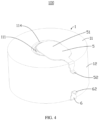
FIG. 1 is a first view of an electrochemical apparatus according to an embodiment of this application. -
FIG. 2 is a second view of an electrochemical apparatus according to an embodiment of this application. -
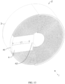
FIG. 3 is a partial cross-sectional view of the electrochemical apparatus inFIG. 1 . -
FIG. 4 is a first view of an electrochemical apparatus according to another embodiment of this application. -
FIG. 5 is a second view of an electrochemical apparatus according to another embodiment of this application. -
FIG. 6 is a partial cross-sectional view of the electrochemical apparatus inFIG. 4 . -
FIG. 7 is a schematic structural diagram of a first electrode according to another embodiment of this application. -
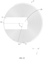
FIG. 8 is a first view of an electrode assembly, a first tab, and a second tab according to another embodiment of this application. -
FIG. 9 is a second view of an electrode assembly, a first tab, and a second tab according to another embodiment of this application. -
FIG. 10 is a third view of an electrode assembly, a first tab, and a second tab according to another embodiment of this application. -
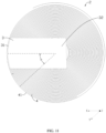
FIG. 11 is a fourth view of an electrode assembly, a first tab, and a second tab according to another embodiment of this application. -
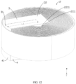
FIG. 12 is a fifth view of an electrode assembly, a first tab, and a second tab according to another embodiment of this application. -
FIG. 13 is a sixth view of an electrode assembly, a first tab, and a second tab according to another embodiment of this application. -
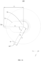
FIG. 14 is a third view of an electrochemical apparatus according to another embodiment of this application. -
FIG. 15 is a plot of magnetic flux density versus θ inTest 1 in this application. -
FIG. 16 is a schematic structural diagram of an electric device according to an embodiment of this application. -
Electrochemical apparatus 100 Housing 1 Top wall 11 First electrode 111 First portion 1111 Third surface 1111a Second portion 1112 First surface 112 Second surface 113 Through hole 114 Side wall 12 Bottom wall 13 Conductive portion 131 Cavity space 14 Electrode assembly 2 First electrode plate 21 First active material layer 211 First end portion 2111 Second electrode plate 22 Second active material layer 221 Second end portion 2211 Separator 23 First tab 3 First connecting zone 31 Third connecting zone 32 Second tab 4 Second connecting zone 41 Fourth connecting zone 42 First connecting member 5 Fifth connecting zone 51 Sixth connecting zone 52 Second connecting member 6 Seventh connecting zone 61 Eighth connecting zone 62 Insulator 7 Electric device 200 Device body 210 Distance between geometric center of first connecting zone and geometric center of third connecting zone L1 Distance between geometric center of second connecting zone and geometric center of fourth connecting zone L2 Distance between geometric center of fifth connecting zone and geometric center of sixth connecting zone L3 Distance between geometric center of seventh connecting zone and geometric center of eighth connecting zone L4 First direction X Second direction Y Third direction Z - This application will be further described with reference to the accompanying drawings in the following specific embodiments.
- The following describes the technical solutions in some embodiments of this application with reference to the accompanying drawings in these embodiments of this application. Apparently, the described embodiments are only some rather than all of the embodiments of this application.
- It should be noted that when one component is assumed as being "connected to" another component, it may be connected to the another component directly or with a component possibly present therebetween. When a component is deemed as being "disposed" on another component, it may be directly disposed on the another component, or there may be a component disposed in between.
- Unless otherwise defined, all technical and scientific terms used herein shall have the same meanings as commonly understood by persons skilled in the art to which this application pertains. The terms used herein in the specification of this application are for description of specific embodiments only without any intention to limit this application.
- An embodiment of this application provides an electrochemical apparatus including a housing, an electrode assembly accommodated in the housing, a first tab, and a second tab. The housing includes a top wall, a side wall, and a bottom wall, the top wall being provided with a first electrode. The electrode assembly includes a first electrode plate and a second electrode plate. The first tab is connected to the first electrode plate and the first electrode. The second tab is connected to the second electrode plate. When viewed in a direction perpendicular to the top wall, an included angle between a length direction of the first tab and a length direction of the second tab is denoted as θ, satisfying: 0° ≤ θ ≤ 60°. When the electrochemical apparatus is in a charging/discharging state, a current direction on the first tab and a current direction on the second tab tend to be opposite, and a magnetic field generated by the first tab and a magnetic field generated by the second tab overlap and can at least partially cancel each other out, so that a magnetic field generated by the electrochemical apparatus is weakened.
- In an example, further description will be made with an example in which the electrochemical apparatus is placed on the horizontal plane, with the bottom wall at the bottom and the top wall at the top.
- The following further describes some embodiments of this application with reference to the accompanying drawings.
- As shown in
FIG. 1 ,FIG. 2 , andFIG. 3 , an embodiment of this application provides anelectrochemical apparatus 100. Theelectrochemical apparatus 100 includes ahousing 1, anelectrode assembly 2, afirst tab 3, and asecond tab 4. Theelectrode assembly 2, thefirst tab 3, and thesecond tab 4 are disposed inside thehousing 1, and theelectrode assembly 2 connects thefirst tab 3 and thesecond tab 4. - The
housing 1 includes atop wall 11, aside wall 12, and abottom wall 13. Thetop wall 11, theside wall 12, and thebottom wall 13 enclose acavity space 14, and theelectrode assembly 2, thefirst tab 3, and thesecond tab 4 are disposed in thecavity space 14. - The
top wall 11 is provided with afirst electrode 111. Thefirst electrode 111 is connected to thefirst tab 3. - In an embodiment, the
top wall 11 is provided with a throughhole 114 and includes afirst surface 112 and asecond surface 113 facing away from each other. The throughhole 114 penetrates thefirst surface 112 and thesecond surface 113. Thefirst surface 112 is located on a side of thetop wall 11 facing thecavity space 14, and thesecond surface 113 is located on a side of thetop wall 11 facing away from thecavity space 14. - At least part of the
first electrode 111 is disposed in the throughhole 114. In an embodiment, theelectrochemical apparatus 100 further includes aninsulator 7. Theinsulator 7 is disposed between thetop wall 11 and thefirst electrode 111. Theinsulator 7 connects thetop wall 11 and thefirst electrode 111 to insulate thetop wall 11 from thefirst electrode 111, reducing a risk of short circuit in theelectrochemical apparatus 100. - In an embodiment, a material of the
first electrode 111 includes but is not limited to aluminum or copper metal. - In an embodiment, the
bottom wall 13 includes aconductive portion 131. Theconductive portion 131 is connected to thesecond tab 4. In an embodiment, theconductive portion 131 includes a metal material. - As shown in
FIG. 4 ,FIG. 5 , andFIG. 6 , in an embodiment, theelectrochemical apparatus 100 may further include a first connectingmember 5 and a second connectingmember 6 disposed outside thehousing 1, where the first connectingmember 5 is connected to thefirst electrode 111 so that the first connectingmember 5 is electrically connected to thefirst tab 3; and the second connectingmember 6 is connected to theconductive portion 131 so that the second connectingmember 6 is electrically connected to thesecond tab 4. The first connectingmember 5 and the second connectingmember 6 can be used to connect an external electric device, so that theelectrochemical apparatus 100 can supply power to the electric device. - In an embodiment, the first connecting
member 5 includes a metal material. In an embodiment, the second connectingmember 6 includes a metal material. - In other embodiments, the
first electrode 111 is disposed in the through hole 114 (not shown in the figure), and theinsulator 7 is disposed between thefirst electrode 111 and the inner wall of the throughhole 114. - As shown in
FIG. 3 andFIG. 7 , thefirst electrode 111 includes afirst portion 1111 and asecond portion 1112. Thefirst portion 1111 has athird surface 1111a, and thesecond portion 1112 protrudes from thethird surface 1111a. Thefirst portion 1111 is disposed in thecavity space 14, and thesecond portion 1112 is located in the throughhole 114. - For ease of understanding and description, further description will be made below with an example in which a direction perpendicular to the
top wall 11 is a third direction Z; and when viewed in the third direction Z, a length direction of thefirst tab 3 is a first direction X, and a length direction of thesecond tab 4 is a second direction Y. - In an embodiment, the
insulator 7 has a ring structure, and thesecond portion 1112 of thefirst electrode 111 passes through the ring structure. - In an embodiment, the
insulator 7 includes but is not limited to sealant. - As shown in
FIG. 8 andFIG. 9 , theelectrode assembly 2 includes afirst electrode plate 21, asecond electrode plate 22, and aseparator 23, and theseparator 23 is disposed between thefirst electrode plate 21 and thesecond electrode plate 22. In an embodiment, thefirst electrode plate 21, theseparator 23, and thesecond electrode plate 22 are wound together. - One of the
first electrode plate 21 and thesecond electrode plate 22 is a positive electrode plate and the other is a negative electrode plate. - One of the
first tab 3 and thesecond tab 4 is a positive electrode tab and the other is a negative electrode tab. - The
first electrode plate 21 includes a firstactive material layer 211, thefirst tab 3 has a first connectingzone 31, and thefirst tab 3 is connected to thefirst electrode plate 21 at the first connectingzone 31. - The
second electrode plate 22 includes a secondactive material layer 221, thesecond tab 4 has a second connectingzone 41, and thesecond tab 4 is connected to thesecond electrode plate 22 at the second connectingzone 41. - In an embodiment, the
first tab 3 is located on a side of theelectrode assembly 2, and thesecond tab 4 is located on the opposite side of theelectrode assembly 2. In other embodiments, thefirst tab 3 and thesecond tab 4 may alternatively be located on a same side of the electrode assembly 2 (not shown in the figure). - With reference to
FIG. 3 ,FIG. 8 , andFIG. 9 , thefirst tab 3 has a third connectingzone 32, and thefirst tab 3 is connected to thefirst electrode 111 at the third connectingzone 32. Thesecond tab 4 has a fourth connectingzone 42, and thesecond tab 4 is connected to thebottom wall 13 at the fourth connectingzone 42. - With reference to
FIG. 8 ,FIG. 9 , andFIG. 10 , in an embodiment, when viewed in the third direction Z, an included angle between the first direction X and the second direction Y is denoted as θ, and 0° ≤ θ ≤ 60°. - In this application, the first direction X (that is, a length direction of the first tab 3) is a direction of a connecting line between a geometric center of the third connecting
zone 32 and a geometric center of the first connectingzone 31, when viewed in the third direction Z. The second direction Y (that is, a length direction of the second tab 4) is a direction of a connecting line between a geometric center of the fourth connectingzone 42 and a geometric center of the second connectingzone 41, when viewed in the third direction Z. θ is an included angle between a ray from an intersection point between the first direction X and the second direction Y to the geometric center of the first connectingzone 31 and a ray from the intersection point to the geometric center of the second connectingzone 41, when viewed in the third direction Z. - When the
electrochemical apparatus 100 is in a charging/discharging state, the magnetic field generated by thefirst tab 3 and the magnetic field generated by thesecond tab 4 can at least partially cancel each other out, so that the magnetic field generated by theelectrochemical apparatus 100 is weakened, thereby reducing the impact of the magnetic field generated by theelectrochemical apparatus 100 on the electric device. - As compared with θ > 60°, when 0° ≤ θ ≤ 60°, the magnetic field generated by the
first tab 3 and the magnetic field generated by thesecond tab 4 cancel each other out well, and the impact of the magnetic field generated by theelectrochemical apparatus 100 on the electric device is small. - As shown in
FIG. 11 , further optionally, 0° ≤ θ ≤ 30°. As compared with 30° < θ ≤ 60°, when 0° ≤ θ ≤ 30°, the magnetic field generated by thefirst tab 3 and the magnetic field generated by thesecond tab 4 cancel each other out better, and the difference in magnetic field strength at various positions of the end face of theelectrochemical apparatus 100 is small. - As shown in
FIG. 12 andFIG. 13 , when viewed in the third direction Z, a distance between the geometric center of the first connectingzone 31 and the geometric center of the third connectingzone 32 is denoted as L1, and a distance between the geometric center of the second connectingzone 41 and the geometric center of the fourth connectingzone 42 is denoted as L2. - Optionally, 0.18 ≤ L1/L2 ≤ 2.75. As compared with other values of L1/L2, when 0.18 ≤ L1/L2 ≤ 2.75, the magnetic field generated by the
first tab 3 and the magnetic field generated by thesecond tab 4 cancel each other out well, and the impact of the magnetic field generated by theelectrochemical apparatus 100 on the electric device is small. - Further optionally, 0.45 ≤ L1/L2 ≤ 2.2. In this case, the magnetic field generated by the
first tab 3 and the magnetic field generated by thesecond tab 4 cancel each other out better, and the difference in magnetic field strength at various positions of the end face of theelectrochemical apparatus 100 is small. - With reference to
FIG. 8 ,FIG. 9 ,FIG. 12 , andFIG. 13 , theelectrode assembly 2 is a wound structure. In an embodiment, the firstactive material layer 211 includes afirst end portion 2111, and thefirst end portion 2111 is disposed at a winding start end of the wound structure; and the secondactive material layer 221 includes asecond end portion 2211, and thesecond end portion 2211 is disposed at the winding start end of the wound structure. - Along a length direction of the
first electrode plate 21, a distance between a geometric center of the first connectingzone 31 and thefirst end portion 2111 is denoted as D1. Along a length direction of thesecond electrode plate 22, a distance between a geometric center of the second connectingzone 41 and thesecond end portion 2211 is denoted as D2. - Optionally, 0.5 ≤
D 1/D2 ≤ 2. As compared with other values of D1/D2, when 0.5 ≤ D1/D2 ≤ 2, a magnetic field generated by thefirst electrode plate 21 and a magnetic field generated by thesecond electrode plate 22 cancel each other out well, and the impact of the magnetic field generated by theelectrochemical apparatus 100 on the electric device is small. - Further optionally, 0.9 ≤ D1/D2 ≤ 1.1. In this case, the magnetic field generated by the
first electrode plate 21 and the magnetic field generated by thesecond electrode plate 22 cancel each other out better, and the difference in magnetic field strength at various positions of the end face of theelectrochemical apparatus 100 is small. - Referring to
FIG. 4 ,FIG. 5 , andFIG. 14 , the first connectingmember 5 includes a fifth connectingzone 51 and a sixth connectingzone 52. The fifth connectingzone 51 is connected to thefirst electrode 111, and the sixth connectingzone 52 is located at an end portion of the first connectingmember 5 away from thefirst electrode 111. The second connectingmember 6 includes a seventh connectingzone 61 and an eighth connectingzone 62. The seventh connectingzone 61 is connected to thebottom wall 13, and the eighth connectingzone 62 is located at an end portion of the second connectingmember 6 away from the seventh connectingzone 61. - When viewed in the third direction Z, a connecting line between a geometric center of the fifth connecting
zone 51 and a geometric center of the sixth connectingzone 52 is denoted as W1, a connecting line between a geometric center of the seventh connectingzone 61 and a geometric center of the eighth connectingzone 62 is denoted as W2, and an included angle between W1 and W2 is denoted as β. In this application, β is an included angle between a ray from an intersection point between W1 and W2 to the geometric center of the sixth connectingzone 52 and a ray from the intersection point to the geometric center of the eighth connectingzone 62, when viewed in the third direction Z. - Optionally, 0° ≤ β ≤ 30°. As compared with β > 30°, when 0° ≤ β ≤ 30°, a magnetic field generated by the first connecting
member 5 and a magnetic field generated by the second connectingmember 6 cancel each other out well, and the impact of the magnetic field generated by theelectrochemical apparatus 100 on the electric device is small. - When viewed in the third direction Z, a distance between the geometric center of the fifth connecting
zone 51 and the geometric center of the sixth connectingzone 52 is denoted as L3, and a distance between the geometric center of the seventh connectingzone 61 and the geometric center of the eighth connectingzone 62 is denoted as L4. - Optionally, 0.45 ≤ L3/L4 ≤ 2.2. As compared with other values of L3/L4, the magnetic field generated by the first connecting
member 5 and the magnetic field generated by the second connectingmember 6 cancel each other out well, and the impact of the magnetic field generated by theelectrochemical apparatus 100 on the electric device is small. - Further optionally, 0.9 ≤ L3/L4 ≤ 1.1. In this case, the magnetic field generated by the first connecting
member 5 and the magnetic field generated by the second connectingmember 6 cancel each other out better, and the difference in magnetic field strength at various positions of the end face of theelectrochemical apparatus 100 is small. - To verify the weakening effect of this application on the magnetic field generated by the
electrochemical apparatus 100, the following comparative tests were conducted. - With the first tab set as a positive electrode tab, the second tab set as a negative electrode tab, the value of L1/L2 set to 0.9335, and the value of the included angle θ changed, the magnetic flux density B1 on the side of the
top wall 11 and the magnetic flux density B2 on the side of thebottom wall 13 were recorded. - In this application, the magnetic flux density, also known as the magnetic induction intensity, can be used to indicate the strength of a magnetic field. A larger value of the magnetic flux density indicates a stronger magnetic field and a smaller weakening effect on the magnetic field generated by the
electrochemical apparatus 100, while a smaller value of the magnetic flux density indicates a weaker magnetic field and a greater weakening effect on the magnetic field generated by theelectrochemical apparatus 100.Table 1 Comparison of records for different included angles θ Angle θ (°) D1/D2 Magnetic flux density B1/10-6 (T) Magnetic flux density B2/10-6 (T) 0 0.9418 4.56 3.39 30 0.9345 5.10 4.12 60 0.9273 6.21 4.85 90 0.9202 8.21 6.54 120 0.9132 10.30 8.93 150 0.9063 10.20 8.65 180 0.8995 9.83 8.23 - The data from the above table was plotted on a graph as shown in
FIG. 12 . - It can be learned from
FIG. 15 and Table 1 that when θ is 0°, the magnetic flux density B1 is 4.56×10⁻⁶ T and the magnetic flux density B2 is 3.39×10⁻⁶ T; when θ is 30°, the magnetic flux density B1 is 5.1×10⁻⁶ T (about 1.12 times that when θ is 0°) and the magnetic flux density B2 is 4.12×10⁻⁶ T (about 1.22 times that when θ is 0°); and when θ is 60°, the magnetic flux density B1 is 6.21×10⁻⁶ T (about 1.36 times that when θ is 0°) and the magnetic flux density B2 is 4.85×10⁻⁶ T (about 1.43 times that when θ is 0°). - When 0° ≤ θ ≤ 30°, a current direction on the
first tab 3 and a current direction on thesecond tab 4 tend to be opposite, the magnetic field generated by thefirst tab 3 and the magnetic field generated by thesecond tab 4 cancel each other out well, and theelectrochemical apparatus 100 has good electromagnetic characteristics. Furthermore, it can be seen fromFIG. 15 that when the included angle θ changes in the range of 0° to 30°, the slopes of the magnetic flux densities B1 and B2 are both small, that is, the difference in the effect of magnetic field cancellation between thefirst tab 3 and thesecond tab 4 is small within this range. - With the first tab set as a positive electrode tab, the second tab set as a negative electrode tab, the included angle θ set to 0°, the value of D1/D2 set to 0.9418, and the value of L1/L2 changed, the magnetic flux density B1 on the side of the
top wall 11 and the magnetic flux density B2 on the side of thebottom wall 13 were recorded.Table 2 Comparison of records of different L1/L2 ratios Angle θ (°) L1/L2 D1/D2 Magnetic flux density B1/10-6 (T) Magnetic flux density B2/10-6 (T) 0 0.18 0.9418 9.2734 6.7656 0 0.27 0.9418 8.8178 6.4300 0 0.36 0.9418 8.3299 6.0896 0 0.45 0.9418 7.7558 5.6966 0 0.51 0.9418 7.3461 5.4147 0 0.59 0.9418 6.6192 4.9062 0 0.68 0.9418 5.9259 4.4009 0 0.76 0.9418 5.4078 3.9927 0 0.85 0.9418 5.0146 3.6726 0 0.93 0.9418 4.6924 3.3387 0 1 0.9418 4.5598 3.4319 0 1.1 0.9418 4.6651 4.2037 0 1.22 0.9418 4.9275 5.1018 0 1.37 0.9418 5.2254 5.7020 0 1.57 0.9418 5.5952 6.3184 0 1.83 0.9418 5.9003 7.0253 0 2.20 0.9418 6.6071 7.7952 0 2.75 0.9418 7.3482 8.4934 - It can be learned from Table 2 that when L1/L2 is 1, the magnetic flux density B1 is about 4.56×10⁻⁶ T and the magnetic flux density B2 is about 3.43×10⁻⁶ T.
- When L1/L2 is 0.45, the magnetic flux density B1 is about 7.76×10⁻⁶ T (about 1.70 times that when L1/L2 is 1) and the magnetic flux density B2 is about 5.70×10⁻⁶ T (about 1.66 times that when L1/L2 is 1).
- When L1/L2 is 1.57, the magnetic flux density B1 is about 5.60×10⁻⁶ T (about 1.23 times that when L1/L2 is 1) and the magnetic flux density B2 is about 6.32×10⁻⁶ T (about 1.84 times that when L1/L2 is 1).
- When L1/L2 is 1.83, the magnetic flux density B1 is about 5.90×10⁻⁶ T (about 1.29 times that when L1/L2 is 1) and the magnetic flux density B2 is about 7.03×10⁻⁶ T (about 2.05 times that when L1/L2 is 1);
- When L1/L2 is 2.20, the magnetic flux density B1 is about 6.61×10⁻⁶ T (about 1.45 times that when L1/L2 is 1) and the magnetic flux density B2 is about 7.80×10⁻⁶ T (about 2.27 times that when L1/L2 is 1).
- Therefore, when 0.45 ≤ L1/L2 ≤ 2.2, the magnetic field generated by the
first tab 3 and the magnetic field generated by thesecond tab 4 cancel each other out well, the magnetic flux densities on the side of thetop wall 11 and the side of thebottom wall 13 are both less than 8×10⁻⁶ T, and theelectrochemical apparatus 100 has good electromagnetic characteristics. In addition, the magnetic field generated by thefirst tab 3 and the magnetic field generated by thesecond tab 4 cancel each other out more evenly, thereby reducing the difference in magnetic field strength at various positions of the end face of the electrochemical apparatus. Further, when 0.45 ≤ L1/L2 ≤ 1.57, compared with the magnetic flux density when L1/L2 is 1, the magnetic flux densities on the side of thetop wall 11 and the side of thebottom wall 13 change slightly, and this can ensure that the entire electrochemical apparatus has good electromagnetic characteristics. - As shown in
FIG. 16 , an embodiment of this application further provides anelectric device 200. Theelectric device 200 includes adevice body 210 and theelectrochemical apparatus 100 according to any one of the foregoing embodiments, and theelectrochemical apparatus 100 is disposed on thedevice body 210. Theelectrochemical apparatus 100 can weaken the magnetic field generated by itself, has good electromagnetic characteristics, and weakens the impact of its own magnetic field on theelectric device 200. - In addition, persons skilled in the art can also make other changes within the spirit of this application. Certainly, these changes made according to the spirit of this application shall fall within the scope of this application.
Claims (10)
- An electrochemical apparatus, comprising:a housing, wherein the housing comprises a top wall, a side wall, and a bottom wall, the top wall being provided with a first electrode;an electrode assembly accommodated in the housing, wherein the electrode assembly comprises a first electrode plate and a second electrode plate;a first tab connected to the first electrode plate and the first electrode; anda second tab connected to the second electrode plate;wherein when viewed in a direction perpendicular to the top wall, an included angle between a length direction of the first tab and a length direction of the second tab is denoted as θ, satisfying: 0° ≤ θ ≤ 60°.
- The electrochemical apparatus according to claim 1, wherein 0° ≤ θ ≤ 30°.
- The electrochemical apparatus according to claim 1, whereinthe first tab comprises a first connecting zone connected to the first electrode plate and a third connecting zone connected to the first electrode;the second tab comprises a second connecting zone connected to the second electrode plate and a fourth connecting zone connected to the housing; andwhen viewed in the direction perpendicular to the top wall, a distance between a geometric center of the first connecting zone and a geometric center of the third connecting zone is denoted as L1, and a distance between a geometric center of the second connecting zone and a geometric center of the fourth connecting zone is denoted as L2, satisfying: 0.18 ≤ L1/L2 ≤ 2.75.
- The electrochemical apparatus according to claim 3, wherein 0.45 ≤ L1/L2 ≤ 2.2.
- The electrochemical apparatus according to claim 1, further comprising:a first connecting member and a second connecting member disposed outside the housing; whereinthe first connecting member comprises a fifth connecting zone connected to the first electrode, and a sixth connecting zone is provided at an end portion of the first connecting member away from the first electrode;the second connecting member comprises a seventh connecting zone connected to the housing, and an eighth connecting zone is provided at an end portion of the second connecting member away from the seventh connecting zone; andwhen viewed in the direction perpendicular to the top wall, a connecting line between a geometric center of the fifth connecting zone and a geometric center of the sixth connecting zone is denoted as W1, a connecting line between a geometric center of the seventh connecting zone and a geometric center of the eighth connecting zone is denoted as W2, and an included angle between W1 and W2 is denoted as β, satisfying: 0° ≤ β ≤ 30°.
- The electrochemical apparatus according to claim 5, wherein when viewed in the direction perpendicular to the top wall, a distance between the geometric center of the fifth connecting zone and the geometric center of the sixth connecting zone is denoted as L3, and a distance between the geometric center of the seventh connecting zone and the geometric center of the eighth connecting zone is denoted as L4, satisfying: 0.45 ≤ L3/L4 ≤ 2.2.
- The electrochemical apparatus according to claim 1, whereinthe electrode assembly is a wound structure;the first electrode plate comprises a first active material layer, the first active material layer comprises a first end portion, and the first end portion is disposed at a winding start end of the wound structure;the second electrode plate comprises a second active material layer, the second active material layer comprises a second end portion, and the second end portion is disposed at the winding start end of the wound structure;the first tab comprises a first connecting zone connected to the first electrode plate;the second tab comprises a second connecting zone connected to the second electrode plate; andalong a length direction of the first electrode plate, a distance between a geometric center of the first connecting zone and the first end portion is denoted as D1; and along a length direction of the second electrode plate, a distance between a geometric center of the second connecting zone and the second end portion is denoted as D2, satisfying: 0.5 ≤ D1/D2 ≤ 2.
- The electrochemical apparatus according to claim 7, wherein 0.9 ≤ D1/D2 ≤ 1.1.
- The electrochemical apparatus according to claim 1, wherein at least one of the following conditions is satisfied:(a) the first tab and the second tab are located on opposite sides of the electrode assembly;(b) the top wall has a first surface and a second surface opposite each other, the top wall is provided with a through hole penetrating the first surface and the second surface, and the first electrode is disposed in the through hole;(c) an insulator is provided between the top wall and the first electrode; or(d) the housing comprises a metal material.
- An electric device, comprising the electrochemical apparatus according to any one of claims 1 to 9.
Applications Claiming Priority (1)
| Application Number | Priority Date | Filing Date | Title |
|---|---|---|---|
| PCT/CN2021/127692 WO2023070591A1 (en) | 2021-10-29 | 2021-10-29 | Electrochemical apparatus and electrical device |
Publications (2)
| Publication Number | Publication Date |
|---|---|
| EP4425621A1 true EP4425621A1 (en) | 2024-09-04 |
| EP4425621A4 EP4425621A4 (en) | 2025-07-30 |
Family
ID=86158910
Family Applications (1)
| Application Number | Title | Priority Date | Filing Date |
|---|---|---|---|
| EP21961943.4A Pending EP4425621A4 (en) | 2021-10-29 | 2021-10-29 | ELECTROCHEMICAL APPARATUS AND ELECTRICAL DEVICE |
Country Status (4)
| Country | Link |
|---|---|
| US (1) | US20240274993A1 (en) |
| EP (1) | EP4425621A4 (en) |
| JP (1) | JP7762802B2 (en) |
| WO (1) | WO2023070591A1 (en) |
Families Citing this family (2)
| Publication number | Priority date | Publication date | Assignee | Title |
|---|---|---|---|---|
| WO2025030287A1 (en) * | 2023-08-04 | 2025-02-13 | 宁德新能源科技有限公司 | Electrochemical apparatus, electrical device, and preparation method for electrochemical apparatus |
| WO2025239533A1 (en) * | 2024-05-13 | 2025-11-20 | 삼성전자주식회사 | Battery including structure for reducing magnetic field, and electronic device including same |
Family Cites Families (11)
| Publication number | Priority date | Publication date | Assignee | Title |
|---|---|---|---|---|
| JP6520097B2 (en) * | 2014-12-11 | 2019-05-29 | 株式会社Gsユアサ | Storage element |
| CN107134596A (en) * | 2017-07-06 | 2017-09-05 | 深圳市力电电池有限公司 | Button cell and button cell preparation method |
| CN210489776U (en) * | 2019-09-11 | 2020-05-08 | 东莞小锂新能源科技有限公司 | Coil core assembly structure of button cell |
| JP7283559B2 (en) | 2019-09-30 | 2023-05-30 | 株式会社村田製作所 | Secondary battery and manufacturing method thereof |
| CN111430588B (en) * | 2020-03-03 | 2023-08-22 | 珠海冠宇电池股份有限公司 | Shell assembly of button cell, button cell and electronic product |
| CN111477823A (en) * | 2020-04-27 | 2020-07-31 | 深圳市汇鑫利电子科技有限公司 | Battery tab, tab PACK processing method, battery finished product and electronic product |
| CN111490220B (en) * | 2020-05-07 | 2025-05-13 | 赣州诺威科技有限公司 | Button battery pole piece, button battery and preparation method thereof |
| CN213401327U (en) * | 2020-09-24 | 2021-06-08 | 曙鹏科技(深圳)有限公司 | Soft package button cell |
| CN213816269U (en) * | 2020-12-21 | 2021-07-27 | 珠海冠宇电池股份有限公司 | Battery |
| CN214313252U (en) * | 2021-01-26 | 2021-09-28 | 广东微电新能源有限公司 | Electrode sheet for battery cell and battery |
| CN113013527B (en) * | 2021-02-25 | 2022-10-14 | 东莞小锂新能源科技有限公司 | Novel button battery and manufacturing and mounting method of shell sealing element structure |
-
2021
- 2021-10-29 JP JP2024525559A patent/JP7762802B2/en active Active
- 2021-10-29 EP EP21961943.4A patent/EP4425621A4/en active Pending
- 2021-10-29 WO PCT/CN2021/127692 patent/WO2023070591A1/en not_active Ceased
-
2024
- 2024-04-29 US US18/648,944 patent/US20240274993A1/en active Pending
Also Published As
| Publication number | Publication date |
|---|---|
| WO2023070591A1 (en) | 2023-05-04 |
| US20240274993A1 (en) | 2024-08-15 |
| JP7762802B2 (en) | 2025-10-30 |
| JP2024541037A (en) | 2024-11-06 |
| EP4425621A4 (en) | 2025-07-30 |
Similar Documents
| Publication | Publication Date | Title |
|---|---|---|
| US20240283107A1 (en) | Electrochemical apparatus and electric device | |
| US20240274993A1 (en) | Electrochemical apparatus and electric device | |
| KR100958649B1 (en) | Battery unit, a winding method thereof, and a lithium secondary battery manufactured using the same | |
| US9698405B2 (en) | Electric connector and battery comprising the same | |
| US12548861B2 (en) | Battery cell with overlap between insulator and connector, battery, and electronic device | |
| EP4020647A1 (en) | Rechargeable battery | |
| US20240030555A1 (en) | Electrode assembly and secondary battery | |
| EP4401184A1 (en) | Electrochemical apparatus and electrical device | |
| US12315960B2 (en) | Current collecting member and manufacturing method thereof, secondary battery and manufacturing method thereof, battery module, and apparatus | |
| US20240405255A1 (en) | Battery cell, battery, and electrical device | |
| WO2023185279A1 (en) | Battery | |
| CN216288852U (en) | Electrochemical device and electric equipment | |
| CN214313252U (en) | Electrode sheet for battery cell and battery | |
| US20110262787A1 (en) | Electrochemical Cell with Reduced Magnetic Field Emission and Corresponding Devices | |
| CN114006021B (en) | Electrochemical devices and electrical equipment | |
| JP2022544426A (en) | Batteries and electrical equipment equipped with them | |
| US20240380074A1 (en) | Battery and electronic device including the same | |
| CN221352981U (en) | Battery and electronic equipment | |
| US20260128477A1 (en) | Electrochemical apparatus and electric device | |
| US20260128479A1 (en) | Electrochemical apparatus and electrical device | |
| CN115036625A (en) | A lithium battery with shielding effect | |
| KR102954989B1 (en) | Secondary battery | |
| CN218300166U (en) | Battery and electronic equipment | |
| CN218849719U (en) | Batteries and Electronics | |
| CN223414250U (en) | Cap assembly, battery and electronic equipment |
Legal Events
| Date | Code | Title | Description |
|---|---|---|---|
| STAA | Information on the status of an ep patent application or granted ep patent |
Free format text: STATUS: THE INTERNATIONAL PUBLICATION HAS BEEN MADE |
|
| PUAI | Public reference made under article 153(3) epc to a published international application that has entered the european phase |
Free format text: ORIGINAL CODE: 0009012 |
|
| STAA | Information on the status of an ep patent application or granted ep patent |
Free format text: STATUS: REQUEST FOR EXAMINATION WAS MADE |
|
| 17P | Request for examination filed |
Effective date: 20240528 |
|
| AK | Designated contracting states |
Kind code of ref document: A1 Designated state(s): AL AT BE BG CH CY CZ DE DK EE ES FI FR GB GR HR HU IE IS IT LI LT LU LV MC MK MT NL NO PL PT RO RS SE SI SK SM TR |
|
| DAV | Request for validation of the european patent (deleted) | ||
| DAX | Request for extension of the european patent (deleted) | ||
| A4 | Supplementary search report drawn up and despatched |
Effective date: 20250630 |
|
| RIC1 | Information provided on ipc code assigned before grant |
Ipc: H01M 10/04 20060101AFI20250624BHEP Ipc: H01M 50/119 20210101ALI20250624BHEP Ipc: H01M 50/533 20210101ALI20250624BHEP Ipc: H01M 50/547 20210101ALI20250624BHEP Ipc: H01M 50/552 20210101ALI20250624BHEP |