EP4425524A1 - Switch control device, battery pack and vehicle including the same - Google Patents
Switch control device, battery pack and vehicle including the same Download PDFInfo
- Publication number
- EP4425524A1 EP4425524A1 EP23206216.6A EP23206216A EP4425524A1 EP 4425524 A1 EP4425524 A1 EP 4425524A1 EP 23206216 A EP23206216 A EP 23206216A EP 4425524 A1 EP4425524 A1 EP 4425524A1
- Authority
- EP
- European Patent Office
- Prior art keywords
- switch
- controller
- control device
- state
- battery pack
- Prior art date
- Legal status (The legal status is an assumption and is not a legal conclusion. Google has not performed a legal analysis and makes no representation as to the accuracy of the status listed.)
- Granted
Links
Images


Classifications
-
- H—ELECTRICITY
- H01—ELECTRIC ELEMENTS
- H01H—ELECTRIC SWITCHES; RELAYS; SELECTORS; EMERGENCY PROTECTIVE DEVICES
- H01H9/00—Details of switching devices, not covered by groups H01H1/00 - H01H7/00
- H01H9/54—Circuit arrangements not adapted to a particular application of the switching device and for which no provision exists elsewhere
-
- B—PERFORMING OPERATIONS; TRANSPORTING
- B60—VEHICLES IN GENERAL
- B60L—PROPULSION OF ELECTRICALLY-PROPELLED VEHICLES; SUPPLYING ELECTRIC POWER FOR AUXILIARY EQUIPMENT OF ELECTRICALLY-PROPELLED VEHICLES; ELECTRODYNAMIC BRAKE SYSTEMS FOR VEHICLES IN GENERAL; MAGNETIC SUSPENSION OR LEVITATION FOR VEHICLES; MONITORING OPERATING VARIABLES OF ELECTRICALLY-PROPELLED VEHICLES; ELECTRIC SAFETY DEVICES FOR ELECTRICALLY-PROPELLED VEHICLES
- B60L1/00—Supplying electric power to auxiliary equipment of vehicles
-
- H—ELECTRICITY
- H01—ELECTRIC ELEMENTS
- H01H—ELECTRIC SWITCHES; RELAYS; SELECTORS; EMERGENCY PROTECTIVE DEVICES
- H01H47/00—Circuit arrangements not adapted to a particular application of the relay and designed to obtain desired operating characteristics or to provide energising current
- H01H47/002—Monitoring or fail-safe circuits
-
- G—PHYSICS
- G01—MEASURING; TESTING
- G01R—MEASURING ELECTRIC VARIABLES; MEASURING MAGNETIC VARIABLES
- G01R31/00—Arrangements for testing electric properties; Arrangements for locating electric faults; Arrangements for electrical testing characterised by what is being tested not provided for elsewhere
- G01R31/327—Testing of circuit interrupters, switches or circuit-breakers
- G01R31/3271—Testing of circuit interrupters, switches or circuit-breakers of high voltage or medium voltage devices
- G01R31/3275—Fault detection or status indication
-
- B—PERFORMING OPERATIONS; TRANSPORTING
- B60—VEHICLES IN GENERAL
- B60L—PROPULSION OF ELECTRICALLY-PROPELLED VEHICLES; SUPPLYING ELECTRIC POWER FOR AUXILIARY EQUIPMENT OF ELECTRICALLY-PROPELLED VEHICLES; ELECTRODYNAMIC BRAKE SYSTEMS FOR VEHICLES IN GENERAL; MAGNETIC SUSPENSION OR LEVITATION FOR VEHICLES; MONITORING OPERATING VARIABLES OF ELECTRICALLY-PROPELLED VEHICLES; ELECTRIC SAFETY DEVICES FOR ELECTRICALLY-PROPELLED VEHICLES
- B60L3/00—Electric devices on electrically-propelled vehicles for safety purposes; Monitoring operating variables, e.g. speed, deceleration or energy consumption
-
- B—PERFORMING OPERATIONS; TRANSPORTING
- B60—VEHICLES IN GENERAL
- B60L—PROPULSION OF ELECTRICALLY-PROPELLED VEHICLES; SUPPLYING ELECTRIC POWER FOR AUXILIARY EQUIPMENT OF ELECTRICALLY-PROPELLED VEHICLES; ELECTRODYNAMIC BRAKE SYSTEMS FOR VEHICLES IN GENERAL; MAGNETIC SUSPENSION OR LEVITATION FOR VEHICLES; MONITORING OPERATING VARIABLES OF ELECTRICALLY-PROPELLED VEHICLES; ELECTRIC SAFETY DEVICES FOR ELECTRICALLY-PROPELLED VEHICLES
- B60L3/00—Electric devices on electrically-propelled vehicles for safety purposes; Monitoring operating variables, e.g. speed, deceleration or energy consumption
- B60L3/0023—Detecting, eliminating, remedying or compensating for drive train abnormalities, e.g. failures within the drive train
- B60L3/0046—Detecting, eliminating, remedying or compensating for drive train abnormalities, e.g. failures within the drive train relating to electric energy storage systems, e.g. batteries or capacitors
-
- B—PERFORMING OPERATIONS; TRANSPORTING
- B60—VEHICLES IN GENERAL
- B60L—PROPULSION OF ELECTRICALLY-PROPELLED VEHICLES; SUPPLYING ELECTRIC POWER FOR AUXILIARY EQUIPMENT OF ELECTRICALLY-PROPELLED VEHICLES; ELECTRODYNAMIC BRAKE SYSTEMS FOR VEHICLES IN GENERAL; MAGNETIC SUSPENSION OR LEVITATION FOR VEHICLES; MONITORING OPERATING VARIABLES OF ELECTRICALLY-PROPELLED VEHICLES; ELECTRIC SAFETY DEVICES FOR ELECTRICALLY-PROPELLED VEHICLES
- B60L3/00—Electric devices on electrically-propelled vehicles for safety purposes; Monitoring operating variables, e.g. speed, deceleration or energy consumption
- B60L3/0023—Detecting, eliminating, remedying or compensating for drive train abnormalities, e.g. failures within the drive train
- B60L3/0084—Detecting, eliminating, remedying or compensating for drive train abnormalities, e.g. failures within the drive train relating to control modules
-
- B—PERFORMING OPERATIONS; TRANSPORTING
- B60—VEHICLES IN GENERAL
- B60L—PROPULSION OF ELECTRICALLY-PROPELLED VEHICLES; SUPPLYING ELECTRIC POWER FOR AUXILIARY EQUIPMENT OF ELECTRICALLY-PROPELLED VEHICLES; ELECTRODYNAMIC BRAKE SYSTEMS FOR VEHICLES IN GENERAL; MAGNETIC SUSPENSION OR LEVITATION FOR VEHICLES; MONITORING OPERATING VARIABLES OF ELECTRICALLY-PROPELLED VEHICLES; ELECTRIC SAFETY DEVICES FOR ELECTRICALLY-PROPELLED VEHICLES
- B60L3/00—Electric devices on electrically-propelled vehicles for safety purposes; Monitoring operating variables, e.g. speed, deceleration or energy consumption
- B60L3/04—Cutting off the power supply under fault conditions
-
- B—PERFORMING OPERATIONS; TRANSPORTING
- B60—VEHICLES IN GENERAL
- B60L—PROPULSION OF ELECTRICALLY-PROPELLED VEHICLES; SUPPLYING ELECTRIC POWER FOR AUXILIARY EQUIPMENT OF ELECTRICALLY-PROPELLED VEHICLES; ELECTRODYNAMIC BRAKE SYSTEMS FOR VEHICLES IN GENERAL; MAGNETIC SUSPENSION OR LEVITATION FOR VEHICLES; MONITORING OPERATING VARIABLES OF ELECTRICALLY-PROPELLED VEHICLES; ELECTRIC SAFETY DEVICES FOR ELECTRICALLY-PROPELLED VEHICLES
- B60L3/00—Electric devices on electrically-propelled vehicles for safety purposes; Monitoring operating variables, e.g. speed, deceleration or energy consumption
- B60L3/12—Recording operating variables ; Monitoring of operating variables
-
- B—PERFORMING OPERATIONS; TRANSPORTING
- B60—VEHICLES IN GENERAL
- B60L—PROPULSION OF ELECTRICALLY-PROPELLED VEHICLES; SUPPLYING ELECTRIC POWER FOR AUXILIARY EQUIPMENT OF ELECTRICALLY-PROPELLED VEHICLES; ELECTRODYNAMIC BRAKE SYSTEMS FOR VEHICLES IN GENERAL; MAGNETIC SUSPENSION OR LEVITATION FOR VEHICLES; MONITORING OPERATING VARIABLES OF ELECTRICALLY-PROPELLED VEHICLES; ELECTRIC SAFETY DEVICES FOR ELECTRICALLY-PROPELLED VEHICLES
- B60L50/00—Electric propulsion with power supplied within the vehicle
- B60L50/50—Electric propulsion with power supplied within the vehicle using propulsion power supplied by batteries or fuel cells
- B60L50/60—Electric propulsion with power supplied within the vehicle using propulsion power supplied by batteries or fuel cells using power supplied by batteries
-
- B—PERFORMING OPERATIONS; TRANSPORTING
- B60—VEHICLES IN GENERAL
- B60R—VEHICLES, VEHICLE FITTINGS, OR VEHICLE PARTS, NOT OTHERWISE PROVIDED FOR
- B60R16/00—Electric or fluid circuits specially adapted for vehicles and not otherwise provided for; Arrangement of elements of electric or fluid circuits specially adapted for vehicles and not otherwise provided for
- B60R16/005—Electro-mechanical devices, e.g. switched
-
- B—PERFORMING OPERATIONS; TRANSPORTING
- B60—VEHICLES IN GENERAL
- B60R—VEHICLES, VEHICLE FITTINGS, OR VEHICLE PARTS, NOT OTHERWISE PROVIDED FOR
- B60R16/00—Electric or fluid circuits specially adapted for vehicles and not otherwise provided for; Arrangement of elements of electric or fluid circuits specially adapted for vehicles and not otherwise provided for
- B60R16/02—Electric or fluid circuits specially adapted for vehicles and not otherwise provided for; Arrangement of elements of electric or fluid circuits specially adapted for vehicles and not otherwise provided for electric constitutive elements
- B60R16/03—Electric or fluid circuits specially adapted for vehicles and not otherwise provided for; Arrangement of elements of electric or fluid circuits specially adapted for vehicles and not otherwise provided for electric constitutive elements for supply of electrical power to vehicle subsystems or for
- B60R16/033—Electric or fluid circuits specially adapted for vehicles and not otherwise provided for; Arrangement of elements of electric or fluid circuits specially adapted for vehicles and not otherwise provided for electric constitutive elements for supply of electrical power to vehicle subsystems or for characterised by the use of electrical cells or batteries
-
- G—PHYSICS
- G01—MEASURING; TESTING
- G01R—MEASURING ELECTRIC VARIABLES; MEASURING MAGNETIC VARIABLES
- G01R19/00—Arrangements for measuring currents or voltages or for indicating presence or sign thereof
- G01R19/145—Indicating the presence of current or voltage
-
- G—PHYSICS
- G01—MEASURING; TESTING
- G01R—MEASURING ELECTRIC VARIABLES; MEASURING MAGNETIC VARIABLES
- G01R31/00—Arrangements for testing electric properties; Arrangements for locating electric faults; Arrangements for electrical testing characterised by what is being tested not provided for elsewhere
- G01R31/327—Testing of circuit interrupters, switches or circuit-breakers
- G01R31/3271—Testing of circuit interrupters, switches or circuit-breakers of high voltage or medium voltage devices
- G01R31/3272—Apparatus, systems or circuits therefor
- G01R31/3274—Details related to measuring, e.g. sensing, displaying or computing; Measuring of variables related to the contact pieces, e.g. wear, position or resistance
-
- H—ELECTRICITY
- H01—ELECTRIC ELEMENTS
- H01M—PROCESSES OR MEANS, e.g. BATTERIES, FOR THE DIRECT CONVERSION OF CHEMICAL ENERGY INTO ELECTRICAL ENERGY
- H01M10/00—Secondary cells; Manufacture thereof
- H01M10/42—Methods or arrangements for servicing or maintenance of secondary cells or secondary half-cells
- H01M10/48—Accumulators combined with arrangements for measuring, testing or indicating the condition of cells, e.g. the level or density of the electrolyte
-
- H—ELECTRICITY
- H02—GENERATION; CONVERSION OR DISTRIBUTION OF ELECTRIC POWER
- H02J—ELECTRIC POWER NETWORKS; CIRCUIT ARRANGEMENTS OR SYSTEMS FOR SUPPLYING OR DISTRIBUTING ELECTRIC POWER; SYSTEMS FOR STORING ELECTRIC ENERGY
- H02J7/00—Circuit arrangements for charging or discharging batteries or for supplying loads from batteries
- H02J7/80—Circuit arrangements for charging or discharging batteries or for supplying loads from batteries including monitoring or indicating arrangements
-
- H—ELECTRICITY
- H02—GENERATION; CONVERSION OR DISTRIBUTION OF ELECTRIC POWER
- H02J—ELECTRIC POWER NETWORKS; CIRCUIT ARRANGEMENTS OR SYSTEMS FOR SUPPLYING OR DISTRIBUTING ELECTRIC POWER; SYSTEMS FOR STORING ELECTRIC ENERGY
- H02J7/00—Circuit arrangements for charging or discharging batteries or for supplying loads from batteries
- H02J7/855—Circuit arrangements for charging or discharging batteries or for supplying loads from batteries with circuits adapted for supplying loads from the battery
Definitions
- the present disclosure relates to a switch control device, and a battery pack and a vehicle including the same.
- a high-voltage battery pack is applied to the environmentally-friendly vehicle to store electric energy obtained from various energy sources.
- a high-voltage electrical system of the vehicle uses high-voltage electric energy provided from a high-voltage battery as driving or electrical energy of the vehicle.
- An output of the high-voltage battery pack may be transferred to or blocked from a load by a high-voltage switch such as a relay, a contactor, or the like.
- a high-voltage switch such as a relay, a contactor, or the like.
- An abnormal operation of the high-voltage switch such as chattering or the like may cause welding of a contact to greatly affect lifespan of the high-voltage switch.
- the abnormal operation of the high-voltage switch may be monitored and detected by a controller such as a microcontroller or the like. However, when the controller abnormally operates due to a reset or the like, there is a problem in which the abnormal operation of the high-voltage switch may not be detected.
- a problem to be solved by the present disclosure is to provide a switch control device capable of detecting a malfunction of a high-voltage switch occurring in a section where a controller abnormally operates, and a battery pack and a vehicle including the switch control device.
- a switch control device may include: a controller configured to output a control signal controlling opening and closing of a switch; a switch driver configured to output a driving signal controlling opening and closing of the switch to the switch according to the control signal; and a counter connected between an output terminal of the switch driver and the switch, configured to receive a state signal indicating an operating state of the controller from the controller, and to count the number of times that the switch is operated in an open or closed state by the driving signal when the state signal indicates an abnormal state of the controller.
- the controller may be further configured to detect the number of malfunctions of the switch while the controller operates in an abnormal state based on the number of times.
- the switch may be a relay or a contactor whose opening and closing is controlled by energization of a coil included in the switch.
- the switch driver may be further configured to output the driving signal to at least one of both ends of the coil.
- the counter may be connected to the output terminal of the switch driver or one of the both ends of the coil.
- the state signal may be a reset signal of the controller.
- the counter may be further configured to start or end the counting of the number of times according to the reset signal.
- the controller may be further configured to determine that a failure occurs in the switch driver when the number of times is greater than or equal to a threshold value.
- a battery pack may include: a battery module; a switch configured to control electrical connection between the battery module and a load of the battery module; and the switch control device according to the embodiment that is configured to control the switch.
- a vehicle may include: the battery pack according to the embodiment; and a load configured to receive electric power from the battery pack.
- a malfunction of a high-voltage switch occurring in a section in which a controller abnormally operates may be detected.
- the term “and/or” includes all of or any combination of a plurality of items that are related and arranged.
- the use of “can” or “may” signifies at least one embodiment of the present disclosure.
- a singular term may include a plural form unless stated in another way.
- first and second terms including ordinal numbers such as first and second will be used only to describe various components, and are not to be interpreted as limiting these components. The terms are only used to differentiate one component from other components. For example, a first constituent element could be termed a second constituent element, and similarly, a second constituent element could be termed a first constituent element, without departing from the scope of the present disclosure.
- constituent element or layer when a constituent element or layer is referred to as being “on,” “connected to,” or “coupled to” another constituent element or layer, it can be directly on, connected to, or coupled to the other constituent element or layer, or one or more intervening constituent elements or layers may be present.
- a constituent element or layer when referred to as being “between” two constituent elements or layers, it can be the only constituent element or layer between the two constituent elements or layers, or one or more intervening constituent elements or layers may also be present.
- Electrically connecting two constituent elements includes directly connecting two constituent elements, and connecting the same with another constituent element therebetween.
- the other constituent element may include a switch, a resistor, a capacitor, or the like.
- an expression of connection signifies electrical connection when an expression of direct connection is not provided.
- FIG. 1 schematically illustrates the switch control device according to the embodiment.
- the switch control device 20 may include a controller 21, a switch driver 22, and a counter 23.
- the controller 21 may output a control signal for controlling opening and closing of the switch 10 to the switch driver 22.
- the controller 21 may output a state signal (e.g., a reset signal) indicating an operating state of the controller 21 to the counter 23.
- the controller 21 may be configured as a processor having a physically structured circuit to perform a function represented by a code or a command included in a program such as a microprocessor, a microcontroller, a central processing unit (CPU), a processor core, a multiprocessor, an application-specific integrated circuit (ASIC), a field-programmable gate array (FPGA), or the like.
- the state of the controller 21 may be monitored by a watchdog component inside the controller 21 or a watchdog circuit outside the controller 21.
- the watchdog component or the watchdog circuit may reset the controller 21 if an abnormal state of the controller 21 is detected. As reset, the controller 21 may output the state signal indicating an abnormal state until it returns to the normal state.
- the switch driver 22 may output a driving signal for controlling opening and closing of the switch 10 according to the control signal received from the controller 21.
- the switch 10 may be configured as a switch element in which a contact state (a closed state of the switch 10) and a non-contact state (an open state of the switch 10) of contacts are controlled by whether a coil is energized.
- the switch element may include a relay, a contactor, or the like.
- the switch driver 22 may be connected to at least one of both ends of the coil for operating the switch 10 to control opening and closing of the switch 10 by controlling energization of the coil using the driving signal.
- the counter 23 may receive the state signal of the controller 21 from the controller 21.
- the counter 23 may be connected between an output terminal of the switch driver 22 and the switch 10 (that is, the counter 23 may be connected to the output terminal of the switch driver 22 or one of both ends of the coil of the switch 10) to count the number of times (hereinafter referred to as the number of switch operations) that the switch 10 is operated in an open or closed state in response to the driving signal output from the switch driver 22.
- the counter 23 counts the number of times that the switch is turned on or off.
- the counter 23 may start or end counting the number of switch operations according to the state signal of the controller 21.
- the counter 23 may start counting the number of switch operations when the state signal received from the controller 21 indicates that the controller 21 enters an abnormal state (e.g., a reset state). The counter 23 may end counting of the number of switch operations when the state signal received from the controller 21 indicates that the controller 21 returns to a normal state.
- an abnormal state e.g., a reset state
- the counter 23 may output to the controller 21 information on the number of switch operations counted while the controller 21 operates in the abnormal state.
- the controller 21 receiving information on the number of switch operations may detect an abnormal operation of the switch 10 based on the number of switch operations.
- the controller 21 may determine that a failure occurs in the switch driver 22, and may notify an upper controller (e.g., a controller of a system (e.g., a vehicle) at which the battery pack 100 is mounted) of the failure.
- the switch driver (22) may not change the status of the switch (10) or may change it once. For example, if the controller (21) operates in an abnormal state, the switch driver (22) may maintain the previous state of the switch (10) for a certain period of time. For example, if the controller (21) operates in an abnormal state, the switch driver (22) may change the state of the switch (10) once (for example, changing from a closed state to an open state).
- the operation of the switch driver (22) while the controller (21) operates in an abnormal state may vary depending on the configuration of the switch driver (22). Therefore, the threshold value may be determined according to the configuration of the switch driver (22). The threshold value may be set to 1 or 2. If chattering occurs, the switch (10) may operate multiple times, so the threshold value man be set to a value greater than 2 to prevent misrecognition.
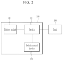
- FIG. 2 schematically illustrates the vehicle including the switch control device 20 according to an embodiment.
- the vehicle may include the battery pack 100 and a load 200 receiving electric power from the battery pack 100.
- the battery pack 100 may include the switch 10, the switch control device 20, and a battery module 30.
- the battery module 30 may include cells connected in series or parallel to each other.
- the switch 10 may control electrical connection between the battery module 30 and the load 200.
- the switch 10 may include a contactor, a relay, or the like.
- the switch control device 20 may control an open or closed state of the switch 10. As described with reference to FIG. 1 , the switch control device 20 may include the controller 21, the switch driver 22, and the counter 23.
- the controller 21 of the switch control device 20 may be a battery management system (BMS) of the battery pack 100.
- BMS battery management system
- the controller 21 may output the state signal indicating the operating state of the controller 21, the control signal for controlling the opening and closing of the switch 10, and the like based on state information of the battery module 30, state information of a system (e.g., the vehicle) at which the battery pack 100 is mounted, a driving mode, or the like.
- the controller 21 may determine whether the switch 10 is opened or closed according to a state of the battery pack 100 or a state of the system (the vehicle) at which the battery pack 100 is mounted, and may output the control signal for controlling the opening and closing of the switch 10 to the switch.
- the switch 10 mounted at the battery pack 100 may abnormally operate due to various factors such as an inrush current, high current conduction, a power noise, a malfunction of the switch driver 22, and the like even while the controller 21 abnormally operates.
- the switch control device 20 may detect the number of times that the switch 10 is abnormally opened or closed while the controller 21 abnormally operates, and may detect the abnormal operation of the switch 10 based on the detected number of times.
- the controller 21 of the switch control device 20 may detect a malfunction of the switch 10 while the controller 21 abnormally operates based on the information on the number of switch operations received from the counter 23.
- the switch control device 20 may provide information on the detected malfunction of the switch to a controller of the system (the vehicle) at which the battery pack 100 is mounted.
- the switch control device 20 may determine that a failure occurs in the switch driver 22, and may notify the controller of the system (the vehicle) at which the battery pack 100 is mounted of the failure of the switch driver 22.
- FIG. 3 schematically illustrates an operating method of the switch control device 20 according to an embodiment.
- the switch control device 20 may determine whether the controller 21 enters the abnormal state based on the state signal (e.g., the reset signal) output from the controller 21 (S11). When the controller 21 enters the abnormal state, the switch control device 20 may count the number of switch operations (S12). The number of switch operations is the number of times that the switch 10 is operated in the open or closed state by the driving signal output from the switch driver 22.
- the switch control device 20 may end counting the number of switch operations (S14). In addition, the switch control device 20 may detect the malfunction of the switch 10 while the controller 21 operates in the abnormal state based on the counted number of switch operations (S15).
- the switch control device 20 may determine that a failure of the switch driver 22 has occurred rather than a temporary malfunction of the switch driver 22 (S17), and may notify an upper controller (e.g., a controller of a system (e.g., a vehicle) at which the battery pack 100 is mounted) of a system at which the switch control device 20 is installed of the failure.
- an upper controller e.g., a controller of a system (e.g., a vehicle) at which the battery pack 100 is mounted
- Electronic or electrical devices may be realized by using appropriate hardware, firmware (e.g., an application-specific integrated circuit), software, or combinations of software, firmware, and hardware.
- firmware e.g., an application-specific integrated circuit
- various configurations of the above-noted devices may be positioned on one integrated circuit (IC) chip or an individual IC chip.
- various configurations of the above-noted devices may be realized on a flexible printed circuit film, a tape carrier package (TCP), a printed circuit board (PCB), or one substrate.
- the electrical or mutual connections described in the present specification may, for example, be realized by the PCB, wires on different types of circuit carriers, or conductive elements.
- the conductive elements may, for example, include metallization such as surface metallizations and/or pins, and may include conductive polymers or ceramics.
- the various configurations of the devices may be performed by at least one processor so as to perform the above-described various functions, they may be performed in at least one computing device, and they may be processes or threads for performing computer program instructions and interacting with other system constituent elements.
- the computer program instruction is stored in a memory realizable in a computing device using a standard memory device such as a random access memory (RAM).
- the computer program instruction may also be stored in a non-transitory computer readable medium such as a CD-ROM or a flash drive.
Landscapes
- Engineering & Computer Science (AREA)
- Power Engineering (AREA)
- Mechanical Engineering (AREA)
- Transportation (AREA)
- Life Sciences & Earth Sciences (AREA)
- Sustainable Development (AREA)
- Sustainable Energy (AREA)
- Physics & Mathematics (AREA)
- General Physics & Mathematics (AREA)
- Chemical & Material Sciences (AREA)
- Chemical Kinetics & Catalysis (AREA)
- Electrochemistry (AREA)
- General Chemical & Material Sciences (AREA)
- Manufacturing & Machinery (AREA)
- Theoretical Computer Science (AREA)
- Charge And Discharge Circuits For Batteries Or The Like (AREA)
- Keying Circuit Devices (AREA)
- Protection Of Static Devices (AREA)
Abstract
Description
- The present disclosure relates to a switch control device, and a battery pack and a vehicle including the same.
- As environmental regulation such as CO2 regulation or the like has been recently strengthened, interest in an environmentally-friendly vehicle has increased. Accordingly, automobile companies are actively conducting research and product development on a pure electric vehicle or a hydrogen vehicle as well as a hybrid vehicle or a plug-in hybrid vehicle.
- A high-voltage battery pack is applied to the environmentally-friendly vehicle to store electric energy obtained from various energy sources. A high-voltage electrical system of the vehicle uses high-voltage electric energy provided from a high-voltage battery as driving or electrical energy of the vehicle.
- An output of the high-voltage battery pack may be transferred to or blocked from a load by a high-voltage switch such as a relay, a contactor, or the like. An abnormal operation of the high-voltage switch such as chattering or the like may cause welding of a contact to greatly affect lifespan of the high-voltage switch. The abnormal operation of the high-voltage switch may be monitored and detected by a controller such as a microcontroller or the like. However, when the controller abnormally operates due to a reset or the like, there is a problem in which the abnormal operation of the high-voltage switch may not be detected.
- A problem to be solved by the present disclosure is to provide a switch control device capable of detecting a malfunction of a high-voltage switch occurring in a section where a controller abnormally operates, and a battery pack and a vehicle including the switch control device.
- A switch control device according to an embodiment for solving the above problem may include: a controller configured to output a control signal controlling opening and closing of a switch; a switch driver configured to output a driving signal controlling opening and closing of the switch to the switch according to the control signal; and a counter connected between an output terminal of the switch driver and the switch, configured to receive a state signal indicating an operating state of the controller from the controller, and to count the number of times that the switch is operated in an open or closed state by the driving signal when the state signal indicates an abnormal state of the controller. The controller may be further configured to detect the number of malfunctions of the switch while the controller operates in an abnormal state based on the number of times.
- The switch may be a relay or a contactor whose opening and closing is controlled by energization of a coil included in the switch. The switch driver may be further configured to output the driving signal to at least one of both ends of the coil.
- The counter may be connected to the output terminal of the switch driver or one of the both ends of the coil.
- The state signal may be a reset signal of the controller. The counter may be further configured to start or end the counting of the number of times according to the reset signal.
- The controller may be further configured to determine that a failure occurs in the switch driver when the number of times is greater than or equal to a threshold value.
- A battery pack according to an embodiment may include: a battery module; a switch configured to control electrical connection between the battery module and a load of the battery module; and the switch control device according to the embodiment that is configured to control the switch.
- A vehicle according to an embodiment may include: the battery pack according to the embodiment; and a load configured to receive electric power from the battery pack.
- According to the present disclosure, a malfunction of a high-voltage switch occurring in a section in which a controller abnormally operates may be detected.
- At least some of the above features that accord with the invention and other features according to the invention are set out in the claims.
-
-
FIG. 1 schematically illustrates a switch control device according to an embodiment. -
FIG. 2 schematically illustrates a vehicle including the switch control device according to an embodiment. -
FIG. 3 schematically illustrates an operating method of the switch control device according to an embodiment. - Embodiments of the present disclosure will now be described in detail with accompanying drawings. Effects and characteristics of embodiments, and a realization method thereof will now be described in detail with accompanying drawings. In the drawings, same reference numerals indicate same constituent elements, and no repeated descriptions thereof will be provided. As those skilled in the art would realize, the described embodiments may be modified in various different ways, all without departing from the scope of the present disclosure. The embodiments are provided as examples to assist the understanding of the invention by a person skilled in the art.
- Hence, for the purpose of understanding the present disclosure, processes, factors, and skills that may be part of the common general knowledge of a person of ordinary skill in the art may not be described. In the drawings, relative sizes of elements, layers, and regions may be exaggerated for clarity.
- In the present specification, the term "and/or" includes all of or any combination of a plurality of items that are related and arranged. When the embodiments of the present disclosure are described, the use of "can" or "may" signifies at least one embodiment of the present disclosure. Regarding the description on an embodiment of the present disclosure, a singular term may include a plural form unless stated in another way.
- In the present specification, terms including ordinal numbers such as first and second will be used only to describe various components, and are not to be interpreted as limiting these components. The terms are only used to differentiate one component from other components. For example, a first constituent element could be termed a second constituent element, and similarly, a second constituent element could be termed a first constituent element, without departing from the scope of the present disclosure.
- It will be understood that when a constituent element or layer is referred to as being "on," "connected to," or "coupled to" another constituent element or layer, it can be directly on, connected to, or coupled to the other constituent element or layer, or one or more intervening constituent elements or layers may be present. In addition, it will also be understood that when a constituent element or layer is referred to as being "between" two constituent elements or layers, it can be the only constituent element or layer between the two constituent elements or layers, or one or more intervening constituent elements or layers may also be present.
- Electrically connecting two constituent elements includes directly connecting two constituent elements, and connecting the same with another constituent element therebetween. The other constituent element may include a switch, a resistor, a capacitor, or the like. When the embodiments are described, an expression of connection signifies electrical connection when an expression of direct connection is not provided.
- Hereinafter, a switch control device according to an embodiment, and a battery pack and a vehicle including the switch control device will be described in detail with reference to necessary drawings.
-
FIG. 1 schematically illustrates the switch control device according to the embodiment. - Referring to
FIG. 1 , theswitch control device 20 according to the embodiment may include acontroller 21, aswitch driver 22, and acounter 23. - The
controller 21 may output a control signal for controlling opening and closing of theswitch 10 to theswitch driver 22. Thecontroller 21 may output a state signal (e.g., a reset signal) indicating an operating state of thecontroller 21 to thecounter 23. Thecontroller 21 may be configured as a processor having a physically structured circuit to perform a function represented by a code or a command included in a program such as a microprocessor, a microcontroller, a central processing unit (CPU), a processor core, a multiprocessor, an application-specific integrated circuit (ASIC), a field-programmable gate array (FPGA), or the like. - The state of the
controller 21 may be monitored by a watchdog component inside thecontroller 21 or a watchdog circuit outside thecontroller 21. The watchdog component or the watchdog circuit may reset thecontroller 21 if an abnormal state of thecontroller 21 is detected. As reset, thecontroller 21 may output the state signal indicating an abnormal state until it returns to the normal state. - The
switch driver 22 may output a driving signal for controlling opening and closing of theswitch 10 according to the control signal received from thecontroller 21. Theswitch 10 may be configured as a switch element in which a contact state (a closed state of the switch 10) and a non-contact state (an open state of the switch 10) of contacts are controlled by whether a coil is energized. For example, the switch element may include a relay, a contactor, or the like. In this case, theswitch driver 22 may be connected to at least one of both ends of the coil for operating theswitch 10 to control opening and closing of theswitch 10 by controlling energization of the coil using the driving signal. - The
counter 23 may receive the state signal of thecontroller 21 from thecontroller 21. Thecounter 23 may be connected between an output terminal of theswitch driver 22 and the switch 10 (that is, thecounter 23 may be connected to the output terminal of theswitch driver 22 or one of both ends of the coil of the switch 10) to count the number of times (hereinafter referred to as the number of switch operations) that theswitch 10 is operated in an open or closed state in response to the driving signal output from theswitch driver 22. In other words, thecounter 23 counts the number of times that the switch is turned on or off. Thecounter 23 may start or end counting the number of switch operations according to the state signal of thecontroller 21. Thecounter 23 may start counting the number of switch operations when the state signal received from thecontroller 21 indicates that thecontroller 21 enters an abnormal state (e.g., a reset state). Thecounter 23 may end counting of the number of switch operations when the state signal received from thecontroller 21 indicates that thecontroller 21 returns to a normal state. - The
counter 23 may output to thecontroller 21 information on the number of switch operations counted while thecontroller 21 operates in the abnormal state. Thecontroller 21 receiving information on the number of switch operations may detect an abnormal operation of theswitch 10 based on the number of switch operations. When the number of switch operations is greater than or equal to a threshold value, thecontroller 21 may determine that a failure occurs in theswitch driver 22, and may notify an upper controller (e.g., a controller of a system (e.g., a vehicle) at which thebattery pack 100 is mounted) of the failure. - If the controller (21) operates in an abnormal state, the switch driver (22) may not change the status of the switch (10) or may change it once. For example, if the controller (21) operates in an abnormal state, the switch driver (22) may maintain the previous state of the switch (10) for a certain period of time. For example, if the controller (21) operates in an abnormal state, the switch driver (22) may change the state of the switch (10) once (for example, changing from a closed state to an open state). The operation of the switch driver (22) while the controller (21) operates in an abnormal state may vary depending on the configuration of the switch driver (22). Therefore, the threshold value may be determined according to the configuration of the switch driver (22). The threshold value may be set to 1 or 2. If chattering occurs, the switch (10) may operate multiple times, so the threshold value man be set to a value greater than 2 to prevent misrecognition.
-
FIG. 2 schematically illustrates the vehicle including theswitch control device 20 according to an embodiment. - Referring to
FIG. 2 , the vehicle may include thebattery pack 100 and aload 200 receiving electric power from thebattery pack 100. Thebattery pack 100 may include theswitch 10, theswitch control device 20, and abattery module 30. - The
battery module 30 may include cells connected in series or parallel to each other. - The
switch 10 may control electrical connection between thebattery module 30 and theload 200. Theswitch 10 may include a contactor, a relay, or the like. - The
switch control device 20 may control an open or closed state of theswitch 10. As described with reference toFIG. 1 , theswitch control device 20 may include thecontroller 21, theswitch driver 22, and thecounter 23. - The
controller 21 of theswitch control device 20 may be a battery management system (BMS) of thebattery pack 100. In this case, thecontroller 21 may output the state signal indicating the operating state of thecontroller 21, the control signal for controlling the opening and closing of theswitch 10, and the like based on state information of thebattery module 30, state information of a system (e.g., the vehicle) at which thebattery pack 100 is mounted, a driving mode, or the like. For example, thecontroller 21 may determine whether theswitch 10 is opened or closed according to a state of thebattery pack 100 or a state of the system (the vehicle) at which thebattery pack 100 is mounted, and may output the control signal for controlling the opening and closing of theswitch 10 to the switch. - The
switch 10 mounted at thebattery pack 100 may abnormally operate due to various factors such as an inrush current, high current conduction, a power noise, a malfunction of theswitch driver 22, and the like even while thecontroller 21 abnormally operates. As described above, theswitch control device 20 may detect the number of times that theswitch 10 is abnormally opened or closed while thecontroller 21 abnormally operates, and may detect the abnormal operation of theswitch 10 based on the detected number of times. - The
controller 21 of theswitch control device 20 may detect a malfunction of theswitch 10 while thecontroller 21 abnormally operates based on the information on the number of switch operations received from thecounter 23. When the malfunction of theswitch 10 is detected, theswitch control device 20 may provide information on the detected malfunction of the switch to a controller of the system (the vehicle) at which thebattery pack 100 is mounted. When the number of switch operations counted while thecontroller 21 abnormally operates is greater than or equal to the threshold value, theswitch control device 20 may determine that a failure occurs in theswitch driver 22, and may notify the controller of the system (the vehicle) at which thebattery pack 100 is mounted of the failure of theswitch driver 22. -
FIG. 3 schematically illustrates an operating method of theswitch control device 20 according to an embodiment. - Referring to
FIG. 3 , theswitch control device 20 according to the embodiment may determine whether thecontroller 21 enters the abnormal state based on the state signal (e.g., the reset signal) output from the controller 21 (S11). When thecontroller 21 enters the abnormal state, theswitch control device 20 may count the number of switch operations (S12). The number of switch operations is the number of times that theswitch 10 is operated in the open or closed state by the driving signal output from theswitch driver 22. - Thereafter, when it is confirmed that the
controller 21 returns to the normal state based on the state signal output from thecontroller 21 in a step S13, theswitch control device 20 may end counting the number of switch operations (S14). In addition, theswitch control device 20 may detect the malfunction of theswitch 10 while thecontroller 21 operates in the abnormal state based on the counted number of switch operations (S15). When the counted number of switch operations is greater than or equal to the threshold value in a step S16, theswitch control device 20 may determine that a failure of theswitch driver 22 has occurred rather than a temporary malfunction of the switch driver 22 (S17), and may notify an upper controller (e.g., a controller of a system (e.g., a vehicle) at which thebattery pack 100 is mounted) of a system at which theswitch control device 20 is installed of the failure. - Electronic or electrical devices according to embodiments of the present disclosure and/or other related devices or constituent elements may be realized by using appropriate hardware, firmware (e.g., an application-specific integrated circuit), software, or combinations of software, firmware, and hardware. For example, various configurations of the above-noted devices may be positioned on one integrated circuit (IC) chip or an individual IC chip. In addition, various configurations of the above-noted devices may be realized on a flexible printed circuit film, a tape carrier package (TCP), a printed circuit board (PCB), or one substrate. The electrical or mutual connections described in the present specification may, for example, be realized by the PCB, wires on different types of circuit carriers, or conductive elements. The conductive elements may, for example, include metallization such as surface metallizations and/or pins, and may include conductive polymers or ceramics.
- In addition, the various configurations of the devices may be performed by at least one processor so as to perform the above-described various functions, they may be performed in at least one computing device, and they may be processes or threads for performing computer program instructions and interacting with other system constituent elements. The computer program instruction is stored in a memory realizable in a computing device using a standard memory device such as a random access memory (RAM). The computer program instruction may also be stored in a non-transitory computer readable medium such as a CD-ROM or a flash drive.
- Further, a person of ordinary skill in the art must understand that various functions of the computing device may be combined or united to a single computing device, or functions of a specific computing device may be dispersed to at least another computing device while not digressing from the range of the embodiments of the present disclosure.
-
- 10: switch
- 20: switch control device
- 21: controller
- 22: switch driver
- 23: counter
- 100: battery pack
- 200: load
Claims (7)
- A switch control device, comprising:a controller configured to output a control signal controlling opening and closing of a switch;a switch driver configured to output a driving signal controlling opening and closing of the switch to the switch according to the control signal; anda counter connected between an output terminal of the switch driver and the switch, configured to receive a state signal indicating an operating state of the controller from the controller, and to count a number of times that the switch is operated in an open or closed state by the driving signal when the state signal indicates an abnormal state of the controller,wherein the controller is further configured to detect a malfunction of the switch while the controller operates in an abnormal state based on the number of times.
- The switch control device of claim 1, wherein the switch is a relay or a contactor whose opening and closing is controlled by energization of a coil included in the switch, and the switch driver is further configured to output the driving signal to at least one of both ends of the coil.
- The switch control device of claim 2, wherein the counter is connected to the output terminal of the switch driver or one of the both ends of the coil.
- The switch control device of any preceding claim, wherein the state signal is a reset signal of the controller, and the counter is further configured to start or end counting of the number of times according to the reset signal.
- The switch control device of any preceding claim, wherein the controller is further configured to determine that a failure occurs in the switch driver when the number of times is greater than or equal to a threshold value.
- A battery pack comprising:a battery module;a switch configured to control electrical connection between the battery module and a load of the battery module; anda switch control device according to any one of claims 1 to 5 that is configured to control the switch.
- A vehicle comprising:a battery pack according to claim 6; anda load configured to receive electric power from the battery pack.
Applications Claiming Priority (1)
| Application Number | Priority Date | Filing Date | Title |
|---|---|---|---|
| KR1020230028669A KR20240135285A (en) | 2023-03-03 | 2023-03-03 | Switch control device, and battery pack and vehicle including the same |
Publications (2)
| Publication Number | Publication Date |
|---|---|
| EP4425524A1 true EP4425524A1 (en) | 2024-09-04 |
| EP4425524B1 EP4425524B1 (en) | 2025-09-03 |
Family
ID=88558496
Family Applications (1)
| Application Number | Title | Priority Date | Filing Date |
|---|---|---|---|
| EP23206216.6A Active EP4425524B1 (en) | 2023-03-03 | 2023-10-26 | Switch control device, battery pack and vehicle including the same |
Country Status (5)
| Country | Link |
|---|---|
| US (1) | US12387885B2 (en) |
| EP (1) | EP4425524B1 (en) |
| KR (1) | KR20240135285A (en) |
| CN (1) | CN118578881A (en) |
| PL (1) | PL4425524T3 (en) |
Citations (3)
| Publication number | Priority date | Publication date | Assignee | Title |
|---|---|---|---|---|
| US20190244779A1 (en) * | 2018-02-08 | 2019-08-08 | Fanuc Corporation | Load driving device and load driving method |
| US10746802B2 (en) * | 2016-07-15 | 2020-08-18 | Lg Chem, Ltd. | System and method for preventing abnormal opening of contactor through real-time operation detection |
| FR3126209A1 (en) * | 2021-08-17 | 2023-02-24 | Psa Automobiles Sa | CONTROL OF THE USE OF SWITCHES FOR COUPLING A VEHICLE ELECTRIC POWER SOURCE TO A POWER SUPPLY NETWORK |
Family Cites Families (8)
| Publication number | Priority date | Publication date | Assignee | Title |
|---|---|---|---|---|
| US4387332A (en) * | 1980-01-29 | 1983-06-07 | Sanyo Electric Co., Ltd. | Apparatus for successively charging rechargeable batteries |
| KR200291562Y1 (en) | 1998-12-12 | 2002-11-18 | 주식회사 포스코 | Apparatus for testing relay |
| CN104247192A (en) * | 2012-04-23 | 2014-12-24 | 奥的斯电梯公司 | Battery Field Disconnect Method |
| US9829529B2 (en) * | 2012-08-14 | 2017-11-28 | Nissan Motor Co., Ltd. | Power supply apparatus |
| US9965365B2 (en) * | 2013-12-31 | 2018-05-08 | Lite-On, Inc. | Power supply failover system and method |
| JP2015217911A (en) | 2014-05-21 | 2015-12-07 | 株式会社デンソー | Electronic control apparatus |
| JP2018156859A (en) | 2017-03-17 | 2018-10-04 | 三菱自動車工業株式会社 | Contactor welding judgment device |
| JP6922723B2 (en) * | 2017-12-26 | 2021-08-18 | トヨタ自動車株式会社 | Fuel cell system |
-
2023
- 2023-03-03 KR KR1020230028669A patent/KR20240135285A/en active Pending
- 2023-10-17 US US18/488,887 patent/US12387885B2/en active Active
- 2023-10-26 EP EP23206216.6A patent/EP4425524B1/en active Active
- 2023-10-26 PL PL23206216.6T patent/PL4425524T3/en unknown
- 2023-10-27 CN CN202311411902.XA patent/CN118578881A/en active Pending
Patent Citations (3)
| Publication number | Priority date | Publication date | Assignee | Title |
|---|---|---|---|---|
| US10746802B2 (en) * | 2016-07-15 | 2020-08-18 | Lg Chem, Ltd. | System and method for preventing abnormal opening of contactor through real-time operation detection |
| US20190244779A1 (en) * | 2018-02-08 | 2019-08-08 | Fanuc Corporation | Load driving device and load driving method |
| FR3126209A1 (en) * | 2021-08-17 | 2023-02-24 | Psa Automobiles Sa | CONTROL OF THE USE OF SWITCHES FOR COUPLING A VEHICLE ELECTRIC POWER SOURCE TO A POWER SUPPLY NETWORK |
Also Published As
| Publication number | Publication date |
|---|---|
| US20240297001A1 (en) | 2024-09-05 |
| KR20240135285A (en) | 2024-09-10 |
| US12387885B2 (en) | 2025-08-12 |
| CN118578881A (en) | 2024-09-03 |
| EP4425524B1 (en) | 2025-09-03 |
| PL4425524T3 (en) | 2025-12-08 |
Similar Documents
| Publication | Publication Date | Title |
|---|---|---|
| US11289925B2 (en) | Battery system including battery modules connected between system terminals and control method thereof | |
| US10153646B2 (en) | Battery overcharge preventing device | |
| US12500428B2 (en) | Battery control device and short-circuit detection method thereof | |
| CN113258631A (en) | Energy storage system protection system | |
| KR102327001B1 (en) | Control system for battery system, battery system, vehicle and operation method of battery system | |
| CN116298853A (en) | Relay detection circuit, battery management system, battery module and energy storage system | |
| US11451049B2 (en) | Device for maintaining operating state of contactor | |
| EP3595076B1 (en) | Battery system | |
| US11495836B2 (en) | Control unit for a battery system | |
| EP4425524A1 (en) | Switch control device, battery pack and vehicle including the same | |
| EP3352322B1 (en) | Control unit for a battery system | |
| EP3534485B1 (en) | Battery pack, battery management system, and method therefor | |
| JP2023009548A (en) | Power control device and semiconductor failure detection method | |
| US11355921B2 (en) | Detecting system for control circuit of load | |
| EP3683087A1 (en) | Relay with temperature sensors for safety applications according to iso 26262 | |
| CN101341641A (en) | Motor control circuit with malfunction monitoring | |
| CN115208222A (en) | Pulse-controlled inverter assembly and method for operating a pulse-controlled inverter assembly | |
| CN115335263A (en) | Control device for controlling a vehicle function of a vehicle and method for operating a control device | |
| KR20200040581A (en) | Battery system for vehicle and the control method of the same | |
| JP2025143012A (en) | battery monitoring device | |
| US11088543B2 (en) | Failure diagnosis system | |
| EP3582247B1 (en) | Relay | |
| CN120028711A (en) | Battery contact fault detection device and method | |
| CN116137435A (en) | Control unit and battery pack |
Legal Events
| Date | Code | Title | Description |
|---|---|---|---|
| PUAI | Public reference made under article 153(3) epc to a published international application that has entered the european phase |
Free format text: ORIGINAL CODE: 0009012 |
|
| STAA | Information on the status of an ep patent application or granted ep patent |
Free format text: STATUS: REQUEST FOR EXAMINATION WAS MADE |
|
| 17P | Request for examination filed |
Effective date: 20231026 |
|
| AK | Designated contracting states |
Kind code of ref document: A1 Designated state(s): AL AT BE BG CH CY CZ DE DK EE ES FI FR GB GR HR HU IE IS IT LI LT LU LV MC ME MK MT NL NO PL PT RO RS SE SI SK SM TR |
|
| GRAP | Despatch of communication of intention to grant a patent |
Free format text: ORIGINAL CODE: EPIDOSNIGR1 |
|
| STAA | Information on the status of an ep patent application or granted ep patent |
Free format text: STATUS: GRANT OF PATENT IS INTENDED |
|
| RIC1 | Information provided on ipc code assigned before grant |
Ipc: B60L 3/04 20060101ALN20250307BHEP Ipc: B60L 3/12 20060101ALI20250307BHEP Ipc: B60L 3/00 20190101ALI20250307BHEP Ipc: H01H 47/00 20060101AFI20250307BHEP |
|
| INTG | Intention to grant announced |
Effective date: 20250325 |
|
| GRAS | Grant fee paid |
Free format text: ORIGINAL CODE: EPIDOSNIGR3 |
|
| GRAA | (expected) grant |
Free format text: ORIGINAL CODE: 0009210 |
|
| STAA | Information on the status of an ep patent application or granted ep patent |
Free format text: STATUS: THE PATENT HAS BEEN GRANTED |
|
| AK | Designated contracting states |
Kind code of ref document: B1 Designated state(s): AL AT BE BG CH CY CZ DE DK EE ES FI FR GB GR HR HU IE IS IT LI LT LU LV MC ME MK MT NL NO PL PT RO RS SE SI SK SM TR |
|
| REG | Reference to a national code |
Ref country code: CH Ref legal event code: EP |
|
| REG | Reference to a national code |
Ref country code: DE Ref legal event code: R096 Ref document number: 602023006346 Country of ref document: DE |
|
| REG | Reference to a national code |
Ref country code: IE Ref legal event code: FG4D |
|
| PGFP | Annual fee paid to national office [announced via postgrant information from national office to epo] |
Ref country code: HU Payment date: 20251112 Year of fee payment: 3 |
|
| REG | Reference to a national code |
Ref country code: NL Ref legal event code: MP Effective date: 20250903 |
|
| PGFP | Annual fee paid to national office [announced via postgrant information from national office to epo] |
Ref country code: DE Payment date: 20251014 Year of fee payment: 3 |
|
| PG25 | Lapsed in a contracting state [announced via postgrant information from national office to epo] |
Ref country code: NO Free format text: LAPSE BECAUSE OF FAILURE TO SUBMIT A TRANSLATION OF THE DESCRIPTION OR TO PAY THE FEE WITHIN THE PRESCRIBED TIME-LIMIT Effective date: 20251203 |
|
| REG | Reference to a national code |
Ref country code: LT Ref legal event code: MG9D |
|
| PGFP | Annual fee paid to national office [announced via postgrant information from national office to epo] |
Ref country code: AT Payment date: 20260113 Year of fee payment: 3 |
|
| PG25 | Lapsed in a contracting state [announced via postgrant information from national office to epo] |
Ref country code: FI Free format text: LAPSE BECAUSE OF FAILURE TO SUBMIT A TRANSLATION OF THE DESCRIPTION OR TO PAY THE FEE WITHIN THE PRESCRIBED TIME-LIMIT Effective date: 20250903 |
|
| PG25 | Lapsed in a contracting state [announced via postgrant information from national office to epo] |
Ref country code: HR Free format text: LAPSE BECAUSE OF FAILURE TO SUBMIT A TRANSLATION OF THE DESCRIPTION OR TO PAY THE FEE WITHIN THE PRESCRIBED TIME-LIMIT Effective date: 20250903 |
|
| PGFP | Annual fee paid to national office [announced via postgrant information from national office to epo] |
Ref country code: FR Payment date: 20251023 Year of fee payment: 3 |
|
| PG25 | Lapsed in a contracting state [announced via postgrant information from national office to epo] |
Ref country code: GR Free format text: LAPSE BECAUSE OF FAILURE TO SUBMIT A TRANSLATION OF THE DESCRIPTION OR TO PAY THE FEE WITHIN THE PRESCRIBED TIME-LIMIT Effective date: 20251204 |
|
| PG25 | Lapsed in a contracting state [announced via postgrant information from national office to epo] |
Ref country code: SE Free format text: LAPSE BECAUSE OF FAILURE TO SUBMIT A TRANSLATION OF THE DESCRIPTION OR TO PAY THE FEE WITHIN THE PRESCRIBED TIME-LIMIT Effective date: 20250903 |
|
| PG25 | Lapsed in a contracting state [announced via postgrant information from national office to epo] |
Ref country code: LV Free format text: LAPSE BECAUSE OF FAILURE TO SUBMIT A TRANSLATION OF THE DESCRIPTION OR TO PAY THE FEE WITHIN THE PRESCRIBED TIME-LIMIT Effective date: 20250903 |
|
| PG25 | Lapsed in a contracting state [announced via postgrant information from national office to epo] |
Ref country code: BG Free format text: LAPSE BECAUSE OF FAILURE TO SUBMIT A TRANSLATION OF THE DESCRIPTION OR TO PAY THE FEE WITHIN THE PRESCRIBED TIME-LIMIT Effective date: 20250903 |
|
| PGFP | Annual fee paid to national office [announced via postgrant information from national office to epo] |
Ref country code: PL Payment date: 20251014 Year of fee payment: 3 |
|
| PG25 | Lapsed in a contracting state [announced via postgrant information from national office to epo] |
Ref country code: RS Free format text: LAPSE BECAUSE OF FAILURE TO SUBMIT A TRANSLATION OF THE DESCRIPTION OR TO PAY THE FEE WITHIN THE PRESCRIBED TIME-LIMIT Effective date: 20251203 |
|
| PG25 | Lapsed in a contracting state [announced via postgrant information from national office to epo] |
Ref country code: ES Free format text: LAPSE BECAUSE OF FAILURE TO SUBMIT A TRANSLATION OF THE DESCRIPTION OR TO PAY THE FEE WITHIN THE PRESCRIBED TIME-LIMIT Effective date: 20250903 |
|
| REG | Reference to a national code |
Ref country code: AT Ref legal event code: MK05 Ref document number: 1834212 Country of ref document: AT Kind code of ref document: T Effective date: 20250903 |
|
| PG25 | Lapsed in a contracting state [announced via postgrant information from national office to epo] |
Ref country code: NL Free format text: LAPSE BECAUSE OF FAILURE TO SUBMIT A TRANSLATION OF THE DESCRIPTION OR TO PAY THE FEE WITHIN THE PRESCRIBED TIME-LIMIT Effective date: 20250903 |
|
| PG25 | Lapsed in a contracting state [announced via postgrant information from national office to epo] |
Ref country code: SM Free format text: LAPSE BECAUSE OF FAILURE TO SUBMIT A TRANSLATION OF THE DESCRIPTION OR TO PAY THE FEE WITHIN THE PRESCRIBED TIME-LIMIT Effective date: 20250903 |
|
| PG25 | Lapsed in a contracting state [announced via postgrant information from national office to epo] |
Ref country code: AT Free format text: LAPSE BECAUSE OF FAILURE TO SUBMIT A TRANSLATION OF THE DESCRIPTION OR TO PAY THE FEE WITHIN THE PRESCRIBED TIME-LIMIT Effective date: 20250903 |
|
| PG25 | Lapsed in a contracting state [announced via postgrant information from national office to epo] |
Ref country code: RO Free format text: LAPSE BECAUSE OF FAILURE TO SUBMIT A TRANSLATION OF THE DESCRIPTION OR TO PAY THE FEE WITHIN THE PRESCRIBED TIME-LIMIT Effective date: 20250903 Ref country code: IT Free format text: LAPSE BECAUSE OF FAILURE TO SUBMIT A TRANSLATION OF THE DESCRIPTION OR TO PAY THE FEE WITHIN THE PRESCRIBED TIME-LIMIT Effective date: 20250903 |
|
| PG25 | Lapsed in a contracting state [announced via postgrant information from national office to epo] |
Ref country code: IS Free format text: LAPSE BECAUSE OF FAILURE TO SUBMIT A TRANSLATION OF THE DESCRIPTION OR TO PAY THE FEE WITHIN THE PRESCRIBED TIME-LIMIT Effective date: 20260103 |
|
| PG25 | Lapsed in a contracting state [announced via postgrant information from national office to epo] |
Ref country code: CZ Free format text: LAPSE BECAUSE OF FAILURE TO SUBMIT A TRANSLATION OF THE DESCRIPTION OR TO PAY THE FEE WITHIN THE PRESCRIBED TIME-LIMIT Effective date: 20250903 Ref country code: PT Free format text: LAPSE BECAUSE OF FAILURE TO SUBMIT A TRANSLATION OF THE DESCRIPTION OR TO PAY THE FEE WITHIN THE PRESCRIBED TIME-LIMIT Effective date: 20260105 |
|
| PG25 | Lapsed in a contracting state [announced via postgrant information from national office to epo] |
Ref country code: EE Free format text: LAPSE BECAUSE OF FAILURE TO SUBMIT A TRANSLATION OF THE DESCRIPTION OR TO PAY THE FEE WITHIN THE PRESCRIBED TIME-LIMIT Effective date: 20250903 Ref country code: SK Free format text: LAPSE BECAUSE OF FAILURE TO SUBMIT A TRANSLATION OF THE DESCRIPTION OR TO PAY THE FEE WITHIN THE PRESCRIBED TIME-LIMIT Effective date: 20250903 |