EP4425517A1 - Spring drive assembly for spring drive of circuit breaker - Google Patents
Spring drive assembly for spring drive of circuit breaker Download PDFInfo
- Publication number
- EP4425517A1 EP4425517A1 EP23160054.5A EP23160054A EP4425517A1 EP 4425517 A1 EP4425517 A1 EP 4425517A1 EP 23160054 A EP23160054 A EP 23160054A EP 4425517 A1 EP4425517 A1 EP 4425517A1
- Authority
- EP
- European Patent Office
- Prior art keywords
- spring
- closing
- limiting disc
- latch lever
- circuit breaker
- Prior art date
- Legal status (The legal status is an assumption and is not a legal conclusion. Google has not performed a legal analysis and makes no representation as to the accuracy of the status listed.)
- Pending
Links
Images




Classifications
-
- H—ELECTRICITY
- H01—ELECTRIC ELEMENTS
- H01H—ELECTRIC SWITCHES; RELAYS; SELECTORS; EMERGENCY PROTECTIVE DEVICES
- H01H3/00—Mechanisms for operating contacts
- H01H3/22—Power arrangements internal to the switch for operating the driving mechanism
- H01H3/30—Power arrangements internal to the switch for operating the driving mechanism using spring motor
- H01H3/3052—Linear spring motors
-
- H—ELECTRICITY
- H01—ELECTRIC ELEMENTS
- H01H—ELECTRIC SWITCHES; RELAYS; SELECTORS; EMERGENCY PROTECTIVE DEVICES
- H01H3/00—Mechanisms for operating contacts
- H01H3/22—Power arrangements internal to the switch for operating the driving mechanism
- H01H3/30—Power arrangements internal to the switch for operating the driving mechanism using spring motor
- H01H3/3031—Means for locking the spring in a charged state
-
- H—ELECTRICITY
- H01—ELECTRIC ELEMENTS
- H01H—ELECTRIC SWITCHES; RELAYS; SELECTORS; EMERGENCY PROTECTIVE DEVICES
- H01H33/00—High-tension or heavy-current switches with arc-extinguishing or arc-preventing means
- H01H33/02—Details
- H01H33/28—Power arrangements internal to the switch for operating the driving mechanism
- H01H33/40—Power arrangements internal to the switch for operating the driving mechanism using spring motor
Definitions
- the present disclosure generally relates to circuit breaker drive mechanisms. More particularly, it relates to providing a spring drive assembly for a spring drive of a circuit breaker, wherein the spring drive assembly comprises a limiting disc and/or a latch lever with multiple recesses.
- Protection systems that include logic circuits, sensors, relays, circuit breakers, fuses, isolators, instrument transformers, and other protection devices, are provided in electrical power systems to control, protect and isolate electrical equipment of the electrical power systems during any electrical fault.
- the electrical fault may correspond to an abnormal condition in the electrical power system, which may damage the electrical equipment and disturb normal flow of electric current in the electrical power system.
- the electrical fault may occur in one or more of three phases or a power line of the electrical power system.
- an Intelligent Electronic Device provided in the electrical power system may sense occurrence of the electrical fault. Thereafter, the lED may cause operation of a circuit breaker to protect an electrical circuit from damage that may be caused due to the electrical fault. For example, the electrical fault may occur due to an overload or a short circuit in the power line in the electrical power system.
- the circuit breaker may interrupt current flow in the power line. Once the electrical fault is cleared, the circuit breaker may be reset or closed to resume normal operation of the power line and the power system, either manually or automatically. To this end, sufficient mechanical power/potential energy is required during an opening operation and a closing operation of the circuit breaker.
- the potential energy required for opening and closing operations of the circuit breaker may be provided by an operating mechanism, such as a spring operating mechanism.
- the spring operating mechanism may have potential energy mechanically stored in springs.
- different spring operating mechanisms such as BLK, BLG, MSD, and FSA, may be used based on a rating of the power line to be isolated or a rating of the circuit breaker.
- FIG. 1A discloses an example spring drive/spring drive mechanism 80 for a circuit breaker 100 according to the prior art.
- the spring drive 80 consists primary of two tension springs, an opening spring 70 and a closing spring 60. Potential energy required for operating the circuit breaker 100 is stored in the opening spring 70 and the closing spring 60.
- the opening spring 70 and the closing spring 60 initiate an opening operation and a closing operation of the circuit breaker 100.
- the closing spring 60 generates a driving force required to close the circuit breaker 100 and charge the opening spring 70.
- the opening spring 70 is directly connected to a link system/contact system 90 of the circuit breaker 100.
- the contact system 90 comprises a fixed contact and a moving contact. As the opening spring 70 is connected to the contact system 90, the potential energy required for the opening operation of the circuit breaker 100 is stored in the opening spring 70 when the circuit breaker 100 is operated in a closed position.
- the opening operation of the circuit breaker 100 On detecting an electrical fault in a power line, the opening operation of the circuit breaker 100 is performed. During the opening operation of the circuit breaker 100, the potential energy stored in the opening spring 70 is discharged. Discharging of the opening spring 70 causes sliding of the moving contact of the circuit breaker 100 in a speedy manner. Subsequently, the moving contact loses physical contact with the fixed contact, thereby the power line may be isolated.
- the closing operation of the circuit breaker 100 is performed.
- the closing spring 60 is discharged to engage the moving contact with the fixed contact. Discharging of the closing spring 60 charges the opening spring, wherein an opening latch (not shown) holds the opening spring 70 in a compressed position until an opening signal releases the opening latch during a next operation of the circuit breaker 100.
- the closing spring 60 is immediately charged and is held in its compressed positon by a closing latch (not shown), until next operation.
- the potential energy stored in the closing spring 60 is converted to kinetic energy. The kinetic energy moves or rotates the moving contact to close the circuit breaker 100.
- FIG. 1B discloses components of the spring drive 80 configured to control the closing operation of the circuit breaker according to the prior art.
- the spring drive 80 comprises the opening spring 70, the closing spring 60, a closing shaft/motor shaft 2, a cam element 14, a cam follower/follower lever 28, and a switching shaft/output shaft 48.
- the closing spring 60 is being operated to discharge. Discharging of the closing spring 60 enables the closing shaft 2 to rotate, which further causes the cam element 14 fixed on the closing shaft 2 to rotate. When the cam element 14 rotates, the cam element 14 touches the cam follower 28 and further causes the cam follower 28 to rotate. Rotation of the cam follower 28 enables the switching shaft 48 to rotate. When the switching shaft 48 rotates, the contacts 90 of the circuit breaker starts operating towards a closed positon from an open position and the opening spring 70 starts charging.
- the cam follower 28 over travels by cam profile. Overtravel of the cam follower 28 enables resetting of an opening latch (which may be used to hold the opening latch in a compressed position). Resetting of the opening latch causes the cam follower 28 to rotate in a reverse direction and while rotating the cam follower 28 can be locked by the opening latch. When the cam follower 28 is locked by the opening latch, the closing shaft 2 is free to oscillate/rotate.
- an opening latch which may be used to hold the opening latch in a compressed position. Resetting of the opening latch causes the cam follower 28 to rotate in a reverse direction and while rotating the cam follower 28 can be locked by the opening latch.
- a limiting disc can be used to control the reverse rotation of the closing shaft 2.
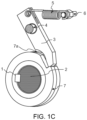
- FIG. 1C discloses a limiting disc arrangement according to the prior art. As depicted in FIG. 1C , the limiting disc 7 is mounted on the closing shaft 2. Further, there exists a latch lever 3 arranged between the limiting disc 7 and a resetting spring 5. The latch lever 3 comprises a pivot pin 4, which enables the latch lever 3 to be in contact with the limiting disc 7.
- the limiting disc 7 comprises a single tooth 7a for controlling the reverse rotation of the closing shaft 2.
- the limiting disc 7 with the single tooth 7a controls the reverse rotation of the closing shaft 2 at a same angle of rotation of the closing shaft 2 (hereinafter referred as stopping angle) corresponding to lower or higher excess amount of energy present in the closing spring at an end of the closing operation of the circuit breaker.
- stopping angle a same angle of rotation of the closing shaft 2
- overtravel of the closing shaft 2 can be high, which directly increases inertia forces/impact force in the limiting disc.
- Increased impact force in the limiting disc may result in a failure of the limiting disc, bending and wear of the pivot pin 4 of the latch lever 3 in the limiting disc 7. Thereby, increasing fatigue life for the limiting disc 7, the latch lever 4, the closing spring and its related components.
- a spring drive assembly for a spring drive of a circuit breaker.
- the spring drive assembly comprises a closing shaft being operatively connected to a closing spring of the circuit breaker.
- the closing shaft being configured to rotate upon spring movement of the closing spring from a charged position to a discharged position.
- the spring drive assembly further comprises a limiting disc operatively connected to the closing shaft and the limiting disc comprises an outer peripheral portion.
- the spring drive assembly further comprises a latch lever.
- the latch lever comprises a first end connected to a resetting spring, a second end configured for sliding contact with the outer peripheral portion of the limiting disc, and a pivot pin for pivotable support of the latch lever and arranged such that the resetting spring causes the second end to be in sliding contact with the outer peripheral portion of the limiting disc.
- the limiting disc and/or the latch lever are operable for controlling reverse rotation of the closing shaft.
- the limiting disc and/or the latch lever comprises a plurality of recesses are configured for providing rotation resistance between the limiting disc and the latch lever upon engagement between the limiting disc and the latch lever by means of said recesses. Thereby controlling reverse rotation of the closing shaft at multiple angles of rotation of the closing shaft when the closing spring is released from the charged position to the discharged position during a closing operation of the circuit breaker.
- the plurality of recesses/teeth on the limiting disc and/or the latch lever may provide flexibility to stop the reverse rotation of the closing shaft and to lock the closing shaft at the multiple angles of rotation of the closing shaft.
- the reverse rotation of the closing shaft may be stopped near to its peak angle when the closing spring discharges.
- overtravel of the closing shaft rotations of the closing shaft exceeding a pre-defined peak angle/angular stroke (hereinafter referred as overtravel of the closing shaft) may be reduced, which further reduces angular speed of the closing shaft and inertial force/impact force in the limiting disc.
- Reduced inertial force in the limiting disc may provide lesser fatigue life for the limiting disc, the latch lever, the closing spring and other related components. Thereby, improving reliability of the overall spring drive.
- the latch lever comprises the plurality of recesses, the plurality of recesses on the latch lever are arranged on the second end with multiple radial distances from a center of the pivot pin of the latch lever.
- the limiting disc comprises the plurality of recesses, the recesses are arranged on the outer peripheral portion of the limiting disc at multiple radial distances from a center of the closing shaft.
- arranging the plurality of recesses on the liming disc or the latch lever by considering the multiple radial distances from the center may allow to:
- the plurality of recesses of the limiting disc arranged on the outer peripheral portion are configured to engage the second end of the latch lever.
- the plurality of recesses arranged on the limiting disc and/or the latch lever is configured to control reverse rotation of the closing shaft reaching a pre-determined peak angle. Thereby, controlling the rotation of the closing shaft at multiple peak angles corresponding to excess amount of energy available in the closing spring over an opening spring of the circuit breaker.
- each of the plurality of recesses on the limiting disc and/or the latch lever may be allowed to act and lock the closing shaft as earliest at lower as well as higher peak angle corresponding to excess amount of energy available in the closing spring and to reduce response time of the latch lever.
- the lesser overtravel of the closing shaft may limit angular speed/rotation speed of the closing shaft and further lowers the impact force in the limiting disc. Thereby, improving robustness of the spring drive to satisfy performance requirement.
- the spring drive assembly disclosed herein may work as a single system for all range of overtravel of the closing shaft with minimum impact force in the limiting disc.
- a design of the spring drive assembly may also be extended to different circuit break applications.
- the spring drive assembly may fit in a given space of the spring drive without increasing overall size of the spring drive of the circuit breaker as well as without affecting functionalities of other components of the spring drive of the circuit breaker.
- the spring drive assembly may also work for lower response time of the latch lever.
- a circuit breaker comprising a closing spring configured to generate driving force for closing the circuit breaker.
- the circuit breaker comprises a spring drive assembly for a spring drive of the circuit breaker.
- the spring drive assembly comprises a closing shaft being operatively connected to a closing spring of the circuit breaker.
- the closing shaft is configured to rotate upon spring movement of the closing spring from a charged position to a discharged position.
- the spring drive assembly further comprises a limiting disc operatively connected to the closing shaft and the limiting disc comprises an outer peripheral portion.
- the spring drive assembly further comprises a latch lever.
- the latch lever comprises a first end connected to a resetting spring, a second end configured for sliding contact with the outer peripheral portion of the limiting disc, and a pivot pin for pivotable support of the latch lever and arranged such that the resetting spring causes the second end to be in sliding contact with the outer peripheral portion of the limiting disc.
- the limiting disc and/or the latch lever are operable for controlling reverse rotation of the closing shaft.
- the limiting disc and/or the latch lever comprises a plurality of recesses are configured for providing rotation resistance between the limiting disc and the latch lever upon engagement between the limiting disc and the latch lever by means of said recesses. Thereby controlling reverse rotation of the closing shaft at multiple angles of rotation of the closing shaft when the closing spring is released from the charged position to the discharged position during a closing operation of the circuit breaker.
- any of the above aspects may additionally have features identical with or corresponding to any of the various features as explained above for any of the other aspects.
- Overtravel of a closing shaft refers to rotation of the closing shaft exceeding a pre-defined angle of rotation/angular stroke to get in a locked condition.
- the overtravel may be a function of excess amount of energy available in a closing spring over an opening spring of the circuit breaker.
- FIGs. 2A , 2B , and 2C disclose a spring drive/spring operating mechanism 80 for a circuit breaker 100.
- the circuit breaker 100 referred herein may be a switching device configured to be operated manually and/or automatically for controlling and protecting an electrical power system.
- the circuit breaker may operate to, for example, control opening and/or closing of a circuit (specifically, a power line) to control flow of current through the circuit.
- the circuit breaker 100 may be provided at terminals of the power line for de-energization of a fault circuit or a faulty power line.
- the circuit breaker 100 referred herein may be high voltage circuit breaker.
- the circuit breaker 100 may comprise fixed contacts and moving contacts, breaker chambers, and insulators.
- the break chambers may include a medium for quenching formation of an electric arc.
- an arc-quenching medium such as oil, vacuum, air, arc chute, magnetic coil, sulphur, or the like, may be provided with the break chambers to increase dielectric strength between the moving and fixed contacts.
- the insulators may be hollow electric insulators that provide an insulating barrier between a live electrical conductor (or the power line) and a metallic conducting body of the circuit breaker 100 that may at ground potential.
- the insulators allow an electrical conductor to pass safely through a conducting barrier.
- the fixed contacts and the moving contacts of the circuit breaker 100 may be physically connected to each other due to applied mechanical pressure on the moving contacts.
- high fault current may flow through a fault power line.
- protection devices such as, a relay, an instrument transformer, a sensor, or the like may detect the high fault current.
- the high fault current may be due to a fault, which includes at least one of: a short circuit fault, an overcurrent fault, an electrical cable fault, or the like.
- an Intelligent Electronic Device, IED may send an opening signal to the circuit breaker 100.
- the circuit breaker 100 may interrupt current flow in the power line.
- the circuit breaker 100 may be reset or closed to resume normal operation of the power line and the electrical power system, either manually or automatically.
- a sufficient mechanical power/potential energy is required for the opening and closing operation of the circuit breaker 100.
- the required potential energy for the opening and closing operation of the circuit breaker 100 may be provided by an operating mechanism, such as the spring drive/spring operating mechanism 80.
- the spring drive/spring operating mechanism 80 may be, but are not limited to, FSA, BLK, BLG, MSD, and so on.
- the spring drive 80 may open the circuit breaker 100 to isolate a faulty electrical circuit during the electrical fault. Upon clearance of the electrical fault, the spring drive 80 may close the circuit breaker 100 to resume normal operation of the power line in the electrical power system.
- the spring drive 80 comprises a closing spring 60, a closing shaft 2, a closing shaft lever 12, a cam element 14, a limit switch 16, a de-coupling strip 18, a stopper bush 20, a stopper lever 22, a worm gear assembly 24, a switching shaft 48, a cam follower 28, a transmission lever 30, a retention lever 32, a tripping latch 34, a trip spring 36, a motor 38, and a gear box 39.
- the spring drive 80 may comprise other components.
- Such components may include but are not limited to, an opening spring, auxiliary contacts, a counter, a position indication, a spring charge indicator, a closing coil, latches, electrical wirings, and so on. Such components are not described in detail for the sake of brevity.
- the closing spring 60 is configured to generate driving force for closing the circuit breaker 100.
- the closing spring 60 may comprise a plurality of closing springs arranged in parallel to each other.
- the closing shaft 2 (also be referred to as first shaft, motor shaft, or the like) may be a tubular splined shaft extending longitudinally along an axial plane of a housing (not shown).
- the housing may provide protective enclosures to components of the spring drive 80.
- the closing shaft 2 may be coupled to the closing spring 60 near a first end of the closing shaft 2.
- an intermediate fitting link may mechanically couple the closing spring 60 to the closing shaft 2.
- the cam element 14 may be arranged on the closing shaft 60.
- the cam element 14 may be provided at a central vertical axis of the closing shaft 2.
- the cam element 14 may have a flat body extending perpendicular to a longitudinal axis of the closing shaft 2.
- the cam element 14 may have a first end and a second end opposite to the first end.
- the first end of the cam element 14 may enclose a portion of the closing shaft 2 while the second end of the cam element 14 may have an arc-shaped cam profile configured to engage with other components of the spring drive 80.
- the switching shaft 48 (also be referred to as second shaft, output shaft, or the like) may be a tubular splined shaft extending longitudinally along an axial plane of the housing, within a same axial plane as the closing shaft 2.
- the switching shaft 48 may be mechanically driven to open or close the circuit breaker 100.
- the switching shaft 48 may be coupled to a moving contact of the circuit breaker. When the moving contact rotates, the moving contact may physically separate or interact with a fixed contact of the circuit breaker 100.
- the switching shaft 48 may also be coupled to the opening spring (not shown in FIGs. 2A-2C ) near a first end of the switching shaft 48.
- the transmission lever 30 may be arranged on the switching shaft 48 that extends parallel to the closing shaft 2.
- the transmission lever 30 may be provided with a roller element like bearing.
- the motor 38 may be coupled to the gear box 39.
- the motor 38 may be configured to drive the gear box 39, which automatically charges the closing spring 60 immediately after each closing operation.
- the tripping latch 34 may be released from the switching shaft 48 and the trip spring 36 hereby may open the circuit breaker 100.
- the closing spring 60 may be operated to discharge. Discharging of the closing spring 60 enables the closing shaft 2 to rotate, which further causes the cam element 14 fixed on the closing shaft 2 to rotate. When the cam element 14 rotates, the cam element 14 touches the cam follower/follower lever 28 and further causes the cam follower 28 to rotate. Rotation of the cam follower 28 enables the switching shaft 48 to rotate. When the switching shaft 48 rotates, the contacts of the circuit breaker 100 starts operating towards the closed positon from the open position and the opening spring starts charging. At the same time, the trip spring 36 in turn may be charged and locked. The motor 38 may then charge the closing spring 60 following each closing operation, via the closing shaft 2 and the worm gear assembly 24. When the closing spring 60 is fully charged, the circuit may be interrupted by the limit switch 16.
- a limiting disc mounted on the closing shaft 2 may be used to control the reverse rotation of the closing shaft 2.
- the limiting disc may comprise a single tooth and may be mounted on the closing shaft 2 with a lever fixed on mechanism.
- the limiting disc 7 with the single tooth 7a controls the reverse rotation of the closing shaft 2 at a same angle of rotation of the closing shaft 2 irrespective of excess energy (lower or higher excess energy) present in the closing spring 60 at an end of the closing operation of the circuit breaker.
- overtravel of the closing shaft 2 can be high, which directly increases inertia forces.
- embodiments herein provide a spring drive assembly 50 for the spring drive 80 of the circuit breaker 100, which controls rotation of the closing shaft 2 at multiple angles of rotation of the closing shaft 2 with respect to excess energy present in the closing spring 60.
- reducing overtravel of the closing shaft 2 which further reduces required inertial forces and improves overall reliability of the spring drive 80 and its components.
- the overtravel of the closing shaft 2 may refer to rotation of the closing shaft 2 exceeding a pre-defined angle of rotation/angular stroke to get in a locked condition.
- the spring drive assembly 50 is formed by the closing shaft 2, a limiting disc 8, a latch lever 3, and a resetting spring 5.
- the closing shaft 2 is configured to rotate upon spring movement of the closing spring 60 from a charged position to a discharged position.
- the limiting disc 8 is operatively connected to the closing shaft 2 and the limiting disc 8 comprises an outer peripheral portion.
- the latch lever 3 comprises a first end, a second end, and a pivot pin. The first end is connected to the resetting spring 5. The second end is configured to be in sliding contact with the outer peripheral portion of the limiting disc 8.
- the pivot pin is for pivotable support of the latch lever.
- the pivot pin is arranged such that the resetting spring 5 causes the second end to be in sliding contact with the outer peripheral portion of the limiting disc 8.
- the limiting disc 8 and the latch lever 3 are operable for controlling the reverse rotation of the closing shaft 2.
- the limiting and/or the latch lever 3 comprises a plurality of recesses/teeth, which are configured for providing rotation resistance between the limiting disc 8 and the latch lever 3 upon engagement between the limiting disc 8 and the latch lever 3 by means of said recesses.
- the reverse rotation of the closing shaft 2 is controlled at multiple angles of rotation of the closing shaft 2 when the closing spring 60 is released from the charged position to the discharged position during the closing operation of the circuit breaker 100.
- FIGs. 3A and 3B disclose the spring drive assembly 50 for the spring drive of the circuit breaker.
- the spring drive assembly comprises a key 1, the closing shaft 2, the latch lever 3, the resetting spring 5, a spring support fixed pin 6, and the limiting disc 8.
- the closing shaft 2 is operatively connected to the closing spring of the circuit breaker.
- the closing shaft 2 is configured to rotate upon spring movement of the closing spring from a charged position to a discharged position.
- the limiting disc 8 is operatively connected to the closing shaft 2.
- the limiting disc 8 comprises an output peripheral portion.
- the latch lever 3 comprises the first end, the second end, and the pivot pin 4.
- the first end is connected to the resetting spring 5.
- the second end is configured for sliding contact with the outer peripheral portion of the limiting disc 8.
- the pivot pin 4 is configured for pivotable support of the latch lever 3.
- the pivot pin 4 may be arranged on the latch lever 3 in accordance with different designs of the latch lever 3 (for example, L-shaped, T-shaped, or the like), and relative position of the latch lever 3.
- the pivot pin 4 is arranged such that the resetting spring 5 causes the second end of the latch lever 3 to be in sliding contact with the outer peripheral portion of the limiting disc 8.
- the limiting disc 8 and the latch lever 3 are operable for controlling reverse rotation of the closing shaft 2.
- the limiting disc 8 and/or the latch lever comprises a plurality of recesses.
- the limiting disc 8 with the plurality of recesses 8a is depicted in FIG. 3A .
- the plurality of recesses 8a of the limiting disc 8 may be arranged on the outer peripheral portion of the limiting disc 8 at multiple radial distances from a center of the closing shaft 2.
- the plurality of recesses 8a of the limiting disc 8 arranged on the outer peripheral portion may be configured to engage with the second end of the latch lever 3.
- the latch lever 3 with the plurality of recesses 3a is depicted in FIG. 3B .
- the plurality of recesses 3a of the latch lever 3 are arranged on the second end of the latch lever 3 at multiple radial distances from a center of the pivot pin 4 of the latch lever 3.
- the plurality of recesses of the latch lever 3 are configured to engage with the outer peripheral portion of the limiting disc 8.
- arranging the plurality of recesses 8a/3a on the liming disc 8 or the latch lever 3 by considering the multiple radial distances from the center may allow to enable the limiting disc 8/latch lever 3 to act at every overtravel of the closing shaft 2 in a same response time of resetting. Further, due to such consideration, a size of the limiting disc 8/latch lever 3 may be made compact for different overtravel of the closing shaft 2.
- the limiting disc 8 and/or the latch lever 3 comprising the plurality of recesses 8a/3a are configured for providing rotation resistance between the limiting disc 8 and the latch lever 3 upon engagement between the limiting disc 8 and the latch lever 3 by means of the plurality of recesses 8a/3a.
- the plurality of recesses 8a/3a arranged on the limiting disc 8 and/or the latch lever 2 may be configured to control reverse rotation of the closing shaft 2 reaching a pre-determined peak angle.
- the rotation of the closing shaft 2 may be controlled at multiple peak angles/multiple angles of rotation of the closing shaft 2 when the closing spring is released from the charged position to the discharged position during the closing operation of the circuit breaker.
- the multiple peak angles may correspond to excess amount of energy available in the closing spring over the opening spring of the circuit breaker.
- each of the plurality of recesses 8a/3a on the limiting disc 8 and/or the latch lever 3 may be allowed to control the reverse rotation of the closing shaft 2 and lock the closing shaft 2 as earliest at lower as well as higher peak angle corresponding to excess amount of energy available in the closing spring.
- Each recesses may be further allowed to reduce response time of the latch lever 3.
- overtravel of the closing shaft 2 may be reduced at higher as well as lower excess amount of energy available in the closing spring.
- the reduced/lesser overtravel of the closing shaft 2 may limit angular speed/rotation speed of the closing shaft 2 and further lowers the impact force in the limiting disc 8. Thereby, improving robustness of the spring drive.
- FIG. 4 discloses an example illustration of rotation of the closing shaft 2 with respect to excess amount of energy present in the closing spring 60 at an end of the closing operation of the circuit breaker 100.
- the closing spring 60 is released from the charged position to the discharged position to discharged energy.
- the closing spring 60 discharges the energy to the closing shaft 2 and reaches to a peak angle, the closing shaft 2 starts reverse rotation.
- velocity of the closing shaft 2 reaches zero and starts to accelerate.
- Rotation of the closing shaft 2 is represented as angle ' ⁇ ' and an excess amount of energy available in the closing spring 60 at an end of the closing operation of the circuit breaker is depicted as angle ' ⁇ ' in FIG. 11.
- the limiting disc with a single tooth (as disclosed in FIG. 1C ) is used to control the reverse rotation of the closing shaft 2.
- the limiting disc with the single tooth may have a same stopping angle (an angle at which the reverse rotation of the closing shaft 2 is controlled) at lower excess amount of energy as well as higher excess amount of energy available in the closing spring 60 (i.e., the angle ' ⁇ ').
- Excess amount of energy left at the end of the closing operation corresponds to different closing spring energy (or pretension) results in different overtravel.
- overtravel of the closing shaft 2 i.e., the angle ' ⁇ '
- the overtravel of the closing shaft 2 may directly increase inertial forces.
- embodiments herein use the limiting disc and/or the latch lever with the plurality of recesses for controlling reverse rotation of the closing shaft 2.
- the reverse rotation of the closing shaft 2 may be controlled at multiple peak angles corresponding to the excess amount of energy available in the closing spring 60 (i.e., the angle ' ⁇ ') over the opening spring of the circuit breaker.
- overtravel of the closing shaft 2 may be reduced while achieving minimum angle ' ⁇ ' with lesser inertial forces, which further reduces the fatigue life for the limiting disc, the latch lever in contact with the limiting disc, the closing spring and related components.
- overall reliability of the spring drive may be improved.
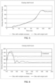
- FIGs. 5, 6 , 7, and 8 are example graphs illustrating comparison results of controlling rotation of the closing shaft using a limiting disc comprising a single tooth and the limiting disc comprising multiple recesses/teeth.
- the closing shaft When the closing spring discharges and reaches a peak angle, the closing shaft starts to rotate in a reverse direction.
- the reverse rotation of the closing shaft is controlled using the limiting disc comprising the single tooth, which has the same stopping irrespective of excess amount of energy available in the closing spring during the closing operation of the circuit breaker.
- the excess amount of energy in the closing spring increases, the rotation of the closing shaft reaches higher peak angle, as depicted in FIG. 5 .
- the overtravel of the closing shaft may be high, as depicted in FIGs. 6 , and 7 .
- Such an overtravel of the closing shaft may increase inertial force/impact force, as depicted in FIG. 8 .
- the limiting disc and/or the latch lever comprising the plurality of recesses/teeth are configured to control rotation of the closing shaft.
- the plurality of recesses arranged on the limiting disc and/or the latch lever controls the reverse rotation of the closing shaft at multiple angles of rotation of the closing shaft (i.e., multiple peak angles) corresponding to the excess amount of energy available in the closing spring over the opening spring of the circuit breaker.
- the angle of rotation may be changed with respect to the excess amount of energy available in the closing spring, the closing shaft may maintain the same angle of rotation at lower as well as higher excess amount of energy available in the closing spring, as depicted in FIG. 5 .
- Embodiments herein illustrate the comparison results by considering the limiting disc and/or the latch lever with two teeth, but it is obvious to a person skilled in the art that more than two teeth may be considered.
Landscapes
- Driving Mechanisms And Operating Circuits Of Arc-Extinguishing High-Tension Switches (AREA)
Abstract
Embodiments herein provide a spring drive assembly (50) for a spring drive (80) of a circuit breaker. The spring drive assembly (50) comprises a closing shaft (2) operatively connected to closing spring (60) of circuit breaker, closing shaft being configured to rotate upon spring movement of closing spring from charged position to discharged position. The spring drive assembly (50) further comprises a limiting disc operatively connected to the closing shaft (2), and limiting disc comprises an outer peripheral portion. The spring drive assembly (50) comprises latch lever (3). The latch lever (3) comprises a first end connected to a resetting spring (5), a second end configured for sliding contact with outer peripheral portion of the limiting disc (8), and pivot pin for pivotable support of latch lever and arranged such that the resetting spring causes second end to be in sliding contact with outer peripheral portion of limiting disc.
Description
- The present disclosure generally relates to circuit breaker drive mechanisms. More particularly, it relates to providing a spring drive assembly for a spring drive of a circuit breaker, wherein the spring drive assembly comprises a limiting disc and/or a latch lever with multiple recesses.
- Protection systems that include logic circuits, sensors, relays, circuit breakers, fuses, isolators, instrument transformers, and other protection devices, are provided in electrical power systems to control, protect and isolate electrical equipment of the electrical power systems during any electrical fault. The electrical fault may correspond to an abnormal condition in the electrical power system, which may damage the electrical equipment and disturb normal flow of electric current in the electrical power system. The electrical fault may occur in one or more of three phases or a power line of the electrical power system.
- During an electrical fault, an Intelligent Electronic Device, IED, provided in the electrical power system may sense occurrence of the electrical fault. Thereafter, the lED may cause operation of a circuit breaker to protect an electrical circuit from damage that may be caused due to the electrical fault. For example, the electrical fault may occur due to an overload or a short circuit in the power line in the electrical power system. In response to detection of the electrical fault by the IED, the circuit breaker may interrupt current flow in the power line. Once the electrical fault is cleared, the circuit breaker may be reset or closed to resume normal operation of the power line and the power system, either manually or automatically. To this end, sufficient mechanical power/potential energy is required during an opening operation and a closing operation of the circuit breaker.
- Moreover, the potential energy required for opening and closing operations of the circuit breaker may be provided by an operating mechanism, such as a spring operating mechanism. The spring operating mechanism may have potential energy mechanically stored in springs. For example, different spring operating mechanisms, such as BLK, BLG, MSD, and FSA, may be used based on a rating of the power line to be isolated or a rating of the circuit breaker.
-
FIG. 1A discloses an example spring drive/spring drive mechanism 80 for acircuit breaker 100 according to the prior art. Thespring drive 80 consists primary of two tension springs, anopening spring 70 and aclosing spring 60. Potential energy required for operating thecircuit breaker 100 is stored in theopening spring 70 and theclosing spring 60. Theopening spring 70 and theclosing spring 60 initiate an opening operation and a closing operation of thecircuit breaker 100. Theclosing spring 60 generates a driving force required to close thecircuit breaker 100 and charge theopening spring 70. Theopening spring 70 is directly connected to a link system/contact system 90 of thecircuit breaker 100. Thecontact system 90 comprises a fixed contact and a moving contact. As theopening spring 70 is connected to thecontact system 90, the potential energy required for the opening operation of thecircuit breaker 100 is stored in theopening spring 70 when thecircuit breaker 100 is operated in a closed position. - On detecting an electrical fault in a power line, the opening operation of the
circuit breaker 100 is performed. During the opening operation of thecircuit breaker 100, the potential energy stored in theopening spring 70 is discharged. Discharging of theopening spring 70 causes sliding of the moving contact of thecircuit breaker 100 in a speedy manner. Subsequently, the moving contact loses physical contact with the fixed contact, thereby the power line may be isolated. - Once the electrical fault is cleared, the closing operation of the
circuit breaker 100 is performed. During the closing operation of thecircuit breaker 100, theclosing spring 60 is discharged to engage the moving contact with the fixed contact. Discharging of theclosing spring 60 charges the opening spring, wherein an opening latch (not shown) holds theopening spring 70 in a compressed position until an opening signal releases the opening latch during a next operation of thecircuit breaker 100. The closingspring 60 is immediately charged and is held in its compressed positon by a closing latch (not shown), until next operation. Thus, during the discharging of theclosing spring 60, the potential energy stored in theclosing spring 60 is converted to kinetic energy. The kinetic energy moves or rotates the moving contact to close thecircuit breaker 100. -
FIG. 1B discloses components of thespring drive 80 configured to control the closing operation of the circuit breaker according to the prior art. As depicted inFIG. 1B , thespring drive 80 comprises theopening spring 70, the closingspring 60, a closing shaft/motor shaft 2, acam element 14, a cam follower/follower lever 28, and a switching shaft/output shaft 48. - During the closing operation of the circuit breaker, the closing
spring 60 is being operated to discharge. Discharging of theclosing spring 60 enables the closingshaft 2 to rotate, which further causes thecam element 14 fixed on the closingshaft 2 to rotate. When thecam element 14 rotates, thecam element 14 touches thecam follower 28 and further causes thecam follower 28 to rotate. Rotation of thecam follower 28 enables the switchingshaft 48 to rotate. When the switchingshaft 48 rotates, thecontacts 90 of the circuit breaker starts operating towards a closed positon from an open position and theopening spring 70 starts charging. - Further, at the end of the closing operation, the
cam follower 28 over travels by cam profile. Overtravel of thecam follower 28 enables resetting of an opening latch (which may be used to hold the opening latch in a compressed position). Resetting of the opening latch causes thecam follower 28 to rotate in a reverse direction and while rotating thecam follower 28 can be locked by the opening latch. When thecam follower 28 is locked by the opening latch, the closingshaft 2 is free to oscillate/rotate. - When the closing
shaft 2 and reaches its peak angle, the closingshaft 2 starts rotating in a reverse direction. A limiting disc can be used to control the reverse rotation of the closingshaft 2. -
FIG. 1C discloses a limiting disc arrangement according to the prior art. As depicted inFIG. 1C , the limitingdisc 7 is mounted on the closingshaft 2. Further, there exists alatch lever 3 arranged between the limitingdisc 7 and aresetting spring 5. Thelatch lever 3 comprises apivot pin 4, which enables thelatch lever 3 to be in contact with the limitingdisc 7. - As depicted in
FIG. 1C , the limitingdisc 7 comprises asingle tooth 7a for controlling the reverse rotation of the closingshaft 2. However, the limitingdisc 7 with thesingle tooth 7a controls the reverse rotation of the closingshaft 2 at a same angle of rotation of the closing shaft 2 (hereinafter referred as stopping angle) corresponding to lower or higher excess amount of energy present in the closing spring at an end of the closing operation of the circuit breaker. Thus, at higher excess amount of energy present in theclosing spring 60, overtravel of the closingshaft 2 can be high, which directly increases inertia forces/impact force in the limiting disc. Increased impact force in the limiting disc may result in a failure of the limiting disc, bending and wear of thepivot pin 4 of thelatch lever 3 in the limitingdisc 7. Thereby, increasing fatigue life for the limitingdisc 7, thelatch lever 4, the closing spring and its related components. - Consequently, there is a need for an arrangement that controls reverse rotation of the closing shaft at multiple angles of rotation of the closing shaft corresponding to excess amount of energy available in the closing spring that alleviates at least some of the above-cited problems.
- It is therefore an object of the present disclosure to provide a spring drive assembly for a spring drive of a circuit breaker, to mitigate, alleviate, or eliminate all or at least some of the above-discussed drawbacks of presently known solutions.
- This and other objects are achieved by means of a spring drive assembly, as defined in the appended claims. The term exemplary is in the present context to be understood as serving as an instance, example or illustration.
- According to a first aspect of the present disclosure, a spring drive assembly for a spring drive of a circuit breaker is provided. The spring drive assembly comprises a closing shaft being operatively connected to a closing spring of the circuit breaker. The closing shaft being configured to rotate upon spring movement of the closing spring from a charged position to a discharged position. The spring drive assembly further comprises a limiting disc operatively connected to the closing shaft and the limiting disc comprises an outer peripheral portion. The spring drive assembly further comprises a latch lever. The latch lever comprises a first end connected to a resetting spring, a second end configured for sliding contact with the outer peripheral portion of the limiting disc, and a pivot pin for pivotable support of the latch lever and arranged such that the resetting spring causes the second end to be in sliding contact with the outer peripheral portion of the limiting disc. The limiting disc and/or the latch lever are operable for controlling reverse rotation of the closing shaft. The limiting disc and/or the latch lever comprises a plurality of recesses are configured for providing rotation resistance between the limiting disc and the latch lever upon engagement between the limiting disc and the latch lever by means of said recesses. Thereby controlling reverse rotation of the closing shaft at multiple angles of rotation of the closing shaft when the closing spring is released from the charged position to the discharged position during a closing operation of the circuit breaker.
- Advantageously, the plurality of recesses/teeth on the limiting disc and/or the latch lever may provide flexibility to stop the reverse rotation of the closing shaft and to lock the closing shaft at the multiple angles of rotation of the closing shaft. The reverse rotation of the closing shaft may be stopped near to its peak angle when the closing spring discharges. As a result, rotations of the closing shaft exceeding a pre-defined peak angle/angular stroke (hereinafter referred as overtravel of the closing shaft) may be reduced, which further reduces angular speed of the closing shaft and inertial force/impact force in the limiting disc. Reduced inertial force in the limiting disc may provide lesser fatigue life for the limiting disc, the latch lever, the closing spring and other related components. Thereby, improving reliability of the overall spring drive.
- In some embodiments, the latch lever comprises the plurality of recesses, the plurality of recesses on the latch lever are arranged on the second end with multiple radial distances from a center of the pivot pin of the latch lever.
- In some embodiments, the limiting disc comprises the plurality of recesses, the recesses are arranged on the outer peripheral portion of the limiting disc at multiple radial distances from a center of the closing shaft.
- Advantageously, arranging the plurality of recesses on the liming disc or the latch lever by considering the multiple radial distances from the center may allow to:
- make a size of the limiting disc/latch lever compact for different overtravel of the closing shaft; and
- enable the limiting disc/latch lever to act at every overtravel of the closing shaft in a same response time of resetting.
- In some embodiments, the plurality of recesses of the limiting disc arranged on the outer peripheral portion are configured to engage the second end of the latch lever.
- In some embodiments, when the closing spring is operated in the discharged position, the plurality of recesses arranged on the limiting disc and/or the latch lever is configured to control reverse rotation of the closing shaft reaching a pre-determined peak angle. Thereby, controlling the rotation of the closing shaft at multiple peak angles corresponding to excess amount of energy available in the closing spring over an opening spring of the circuit breaker.
- Advantageously, each of the plurality of recesses on the limiting disc and/or the latch lever may be allowed to act and lock the closing shaft as earliest at lower as well as higher peak angle corresponding to excess amount of energy available in the closing spring and to reduce response time of the latch lever. Thus, resulting in lesser overtravel of the closing shaft at higher as well as lower excess amount of energy available in the closing spring. The lesser overtravel of the closing shaft may limit angular speed/rotation speed of the closing shaft and further lowers the impact force in the limiting disc. Thereby, improving robustness of the spring drive to satisfy performance requirement.
- Further, the spring drive assembly disclosed herein may work as a single system for all range of overtravel of the closing shaft with minimum impact force in the limiting disc. In addition, a design of the spring drive assembly may also be extended to different circuit break applications.
- Furthermore, the spring drive assembly may fit in a given space of the spring drive without increasing overall size of the spring drive of the circuit breaker as well as without affecting functionalities of other components of the spring drive of the circuit breaker. The spring drive assembly may also work for lower response time of the latch lever.
- According to a second aspect of the present disclosure, a circuit breaker is provided. The circuit breaker comprises a closing spring configured to generate driving force for closing the circuit breaker. The circuit breaker comprises a spring drive assembly for a spring drive of the circuit breaker. The spring drive assembly comprises a closing shaft being operatively connected to a closing spring of the circuit breaker. The closing shaft is configured to rotate upon spring movement of the closing spring from a charged position to a discharged position. The spring drive assembly further comprises a limiting disc operatively connected to the closing shaft and the limiting disc comprises an outer peripheral portion. The spring drive assembly further comprises a latch lever. The latch lever comprises a first end connected to a resetting spring, a second end configured for sliding contact with the outer peripheral portion of the limiting disc, and a pivot pin for pivotable support of the latch lever and arranged such that the resetting spring causes the second end to be in sliding contact with the outer peripheral portion of the limiting disc. The limiting disc and/or the latch lever are operable for controlling reverse rotation of the closing shaft. The limiting disc and/or the latch lever comprises a plurality of recesses are configured for providing rotation resistance between the limiting disc and the latch lever upon engagement between the limiting disc and the latch lever by means of said recesses. Thereby controlling reverse rotation of the closing shaft at multiple angles of rotation of the closing shaft when the closing spring is released from the charged position to the discharged position during a closing operation of the circuit breaker.
- Thus, scaling the limiting disc and/or the latch lever with the plurality of recesses for controlling the reverse rotation of the closing shaft at the multiple angles corresponding to different excess energy of circuit breaker mechanisms. Thus, improving reliability of the spring drive of the circuit breaker.
- In some embodiments, any of the above aspects may additionally have features identical with or corresponding to any of the various features as explained above for any of the other aspects.
- Other advantages may be readily apparent to one having skill in the art. Certain embodiments may have some, or all of the recited advantages.
- The foregoing will be apparent from the following more particular description of the example embodiments, as illustrated in the accompanying drawings in which like reference characters refer to the same parts throughout the different views. The drawings are not necessarily to scale, emphasis instead being placed upon illustrating the example embodiments.
- FIG. 1A
- discloses an example an example spring drive/spring drive mechanism for a circuit breaker according to the prior art;
- FIG. 1B
- discloses components of a spring drive configured to control a closing operation of a circuit breaker according to the prior art;
- FIG. 1C
- discloses a limiting disc arrangement according to the prior art;
- FIGS. 2A, 2B, and 2C
- disclose a spring drive/spring operating mechanism of a circuit breaker in which embodiments of the present disclosure may be implemented;
- FIGS. 3A and 3B .
- disclose a spring drive assembly for a spring drive of a circuit breaker according to some examples;
- FIG. 4
- discloses an example illustration of rotation of a closing shaft with respect to excess amount of energy present in a closing spring at an end of a closing operation of a circuit breaker according to some examples; and
- FIGS. 5, 6, 7, and 8
- are example graphs illustrating comparison results of controlling rotation of a closing shaft using a limiting disc comprising a single tooth and a limiting disc comprising multiple recesses/teeth according to some examples.
- Aspects of the present disclosure will be described more fully hereinafter with reference to the accompanying drawings. The apparatus and methods disclosed herein can, however, be realized in many different forms and should not be construed as being limited to the aspects set forth herein. Like numbers in the drawings refer to like elements throughout.
- The terminology used herein is for the purpose of describing particular aspects of the disclosure only and is not intended to limit the invention. It should be emphasized that the term "comprises/comprising" when used in this specification is taken to specify the presence of stated features, integers, steps, or components, but does not preclude the presence or addition of one or more other features, integers, steps, components, or groups thereof. As used herein, the singular forms "a", "an" and "the" are intended to include the plural forms as well, unless the context clearly indicates otherwise.
- Overtravel of a closing shaft: As used herein, overtravel of the closing shaft refers to rotation of the closing shaft exceeding a pre-defined angle of rotation/angular stroke to get in a locked condition. The overtravel may be a function of excess amount of energy available in a closing spring over an opening spring of the circuit breaker.
-
FIGs. 2A ,2B , and2C disclose a spring drive/spring operating mechanism 80 for acircuit breaker 100. Thecircuit breaker 100 referred herein may be a switching device configured to be operated manually and/or automatically for controlling and protecting an electrical power system. For example, the circuit breaker may operate to, for example, control opening and/or closing of a circuit (specifically, a power line) to control flow of current through the circuit. As would be understood, thecircuit breaker 100 may be provided at terminals of the power line for de-energization of a fault circuit or a faulty power line. - In some examples, the
circuit breaker 100 referred herein may be high voltage circuit breaker. In some examples, thecircuit breaker 100 may comprise fixed contacts and moving contacts, breaker chambers, and insulators. The break chambers may include a medium for quenching formation of an electric arc. Typically, due to high fault current, the electric arc may be formed between the moving contacts and the fixed contacts at a contact point when the contacts separate. Therefore, to this end, an arc-quenching medium such as oil, vacuum, air, arc chute, magnetic coil, sulphur, or the like, may be provided with the break chambers to increase dielectric strength between the moving and fixed contacts. The insulators may be hollow electric insulators that provide an insulating barrier between a live electrical conductor (or the power line) and a metallic conducting body of thecircuit breaker 100 that may at ground potential. The insulators allow an electrical conductor to pass safely through a conducting barrier. - Under normal operating condition of the electrical power system, the fixed contacts and the moving contacts of the
circuit breaker 100 may be physically connected to each other due to applied mechanical pressure on the moving contacts. During a fault, high fault current may flow through a fault power line. In some examples, protection devices such as, a relay, an instrument transformer, a sensor, or the like may detect the high fault current. In some examples, the high fault current may be due to a fault, which includes at least one of: a short circuit fault, an overcurrent fault, an electrical cable fault, or the like. On detecting the high fault current, an Intelligent Electronic Device, IED, may send an opening signal to thecircuit breaker 100. On receiving the opening signal, thecircuit breaker 100 may interrupt current flow in the power line. Once the fault is cleared, thecircuit breaker 100 may be reset or closed to resume normal operation of the power line and the electrical power system, either manually or automatically. A sufficient mechanical power/potential energy is required for the opening and closing operation of thecircuit breaker 100. The required potential energy for the opening and closing operation of thecircuit breaker 100 may be provided by an operating mechanism, such as the spring drive/spring operating mechanism 80. Examples of the spring drive/spring operating mechanism 80 may be, but are not limited to, FSA, BLK, BLG, MSD, and so on. - The
spring drive 80 may open thecircuit breaker 100 to isolate a faulty electrical circuit during the electrical fault. Upon clearance of the electrical fault, thespring drive 80 may close thecircuit breaker 100 to resume normal operation of the power line in the electrical power system. - As depicted in
FIGs. 2A ,2B , and2C , thespring drive 80 comprises aclosing spring 60, a closingshaft 2, a closingshaft lever 12, acam element 14, alimit switch 16, ade-coupling strip 18, astopper bush 20, astopper lever 22, aworm gear assembly 24, a switchingshaft 48, acam follower 28, atransmission lever 30, aretention lever 32, a trippinglatch 34, atrip spring 36, amotor 38, and agear box 39. As would be understood, thespring drive 80 may comprise other components. Examples of such components may include but are not limited to, an opening spring, auxiliary contacts, a counter, a position indication, a spring charge indicator, a closing coil, latches, electrical wirings, and so on. Such components are not described in detail for the sake of brevity. - The closing
spring 60 is configured to generate driving force for closing thecircuit breaker 100. In some examples, the closingspring 60 may comprise a plurality of closing springs arranged in parallel to each other. - The closing shaft 2 (also be referred to as first shaft, motor shaft, or the like) may be a tubular splined shaft extending longitudinally along an axial plane of a housing (not shown). The housing may provide protective enclosures to components of the
spring drive 80. The closingshaft 2 may be coupled to theclosing spring 60 near a first end of the closingshaft 2. In some examples, an intermediate fitting link may mechanically couple theclosing spring 60 to the closingshaft 2. - The
cam element 14 may be arranged on the closingshaft 60. In some examples, thecam element 14 may be provided at a central vertical axis of the closingshaft 2. Thecam element 14 may have a flat body extending perpendicular to a longitudinal axis of the closingshaft 2. Thecam element 14 may have a first end and a second end opposite to the first end. In particular, the first end of thecam element 14 may enclose a portion of the closingshaft 2 while the second end of thecam element 14 may have an arc-shaped cam profile configured to engage with other components of thespring drive 80. - The switching shaft 48 (also be referred to as second shaft, output shaft, or the like) may be a tubular splined shaft extending longitudinally along an axial plane of the housing, within a same axial plane as the closing
shaft 2. The switchingshaft 48 may be mechanically driven to open or close thecircuit breaker 100. In particular, the switchingshaft 48 may be coupled to a moving contact of the circuit breaker. When the moving contact rotates, the moving contact may physically separate or interact with a fixed contact of thecircuit breaker 100. As would be understood, the switchingshaft 48 may also be coupled to the opening spring (not shown inFIGs. 2A-2C ) near a first end of the switchingshaft 48. - The
transmission lever 30 may be arranged on the switchingshaft 48 that extends parallel to the closingshaft 2. Thetransmission lever 30 may be provided with a roller element like bearing. - The
motor 38 may be coupled to thegear box 39. Themotor 38 may be configured to drive thegear box 39, which automatically charges the closingspring 60 immediately after each closing operation. - As depicted in
FIG. 2C , when thecircuit breaker 100 is to be operated in an open position, the trippinglatch 34 may be released from the switchingshaft 48 and thetrip spring 36 hereby may open thecircuit breaker 100. - As depicted in
FIGs. 2A and2B , when thecircuit breaker 100 is to be operated in a closed position, the closingspring 60 may be operated to discharge. Discharging of theclosing spring 60 enables the closingshaft 2 to rotate, which further causes thecam element 14 fixed on the closingshaft 2 to rotate. When thecam element 14 rotates, thecam element 14 touches the cam follower/follower lever 28 and further causes thecam follower 28 to rotate. Rotation of thecam follower 28 enables the switchingshaft 48 to rotate. When the switchingshaft 48 rotates, the contacts of thecircuit breaker 100 starts operating towards the closed positon from the open position and the opening spring starts charging. At the same time, thetrip spring 36 in turn may be charged and locked. Themotor 38 may then charge theclosing spring 60 following each closing operation, via the closingshaft 2 and theworm gear assembly 24. When theclosing spring 60 is fully charged, the circuit may be interrupted by thelimit switch 16. - Further, during the closing operation of the
circuit breaker 100, when theclosing spring 60 discharges energy to the closingshaft 2 and reaches to a peak angle, the closingshaft 2 may start rotate in a reverse direction. According to the prior art (as disclosed inFIG. 1C ), a limiting disc mounted on the closingshaft 2 may be used to control the reverse rotation of the closingshaft 2. The limiting disc may comprise a single tooth and may be mounted on the closingshaft 2 with a lever fixed on mechanism. However, the limitingdisc 7 with thesingle tooth 7a controls the reverse rotation of the closingshaft 2 at a same angle of rotation of the closingshaft 2 irrespective of excess energy (lower or higher excess energy) present in theclosing spring 60 at an end of the closing operation of the circuit breaker. Thus, at higher excess energy present in theclosing spring 60, overtravel of the closingshaft 2 can be high, which directly increases inertia forces. As a result, there may be lesser fatigue life for the limiting disc, the closing/opening spring and its related components. - In contrast to the prior art, embodiments herein provide a
spring drive assembly 50 for thespring drive 80 of thecircuit breaker 100, which controls rotation of the closingshaft 2 at multiple angles of rotation of the closingshaft 2 with respect to excess energy present in theclosing spring 60. Thus, reducing overtravel of the closingshaft 2, which further reduces required inertial forces and improves overall reliability of thespring drive 80 and its components. In some examples, the overtravel of the closingshaft 2 may refer to rotation of the closingshaft 2 exceeding a pre-defined angle of rotation/angular stroke to get in a locked condition. - According to emboidments herein, the
spring drive assembly 50 is formed by the closingshaft 2, a limitingdisc 8, alatch lever 3, and aresetting spring 5. The closingshaft 2 is configured to rotate upon spring movement of theclosing spring 60 from a charged position to a discharged position. The limitingdisc 8 is operatively connected to the closingshaft 2 and the limitingdisc 8 comprises an outer peripheral portion. Thelatch lever 3 comprises a first end, a second end, and a pivot pin. The first end is connected to the resettingspring 5. The second end is configured to be in sliding contact with the outer peripheral portion of the limitingdisc 8. The pivot pin is for pivotable support of the latch lever. The pivot pin is arranged such that the resettingspring 5 causes the second end to be in sliding contact with the outer peripheral portion of the limitingdisc 8. - The limiting
disc 8 and thelatch lever 3 are operable for controlling the reverse rotation of the closingshaft 2. The limiting and/or thelatch lever 3 comprises a plurality of recesses/teeth, which are configured for providing rotation resistance between the limitingdisc 8 and thelatch lever 3 upon engagement between the limitingdisc 8 and thelatch lever 3 by means of said recesses. Thereby, the reverse rotation of the closingshaft 2 is controlled at multiple angles of rotation of the closingshaft 2 when theclosing spring 60 is released from the charged position to the discharged position during the closing operation of thecircuit breaker 100. - Various embodiments describing the
spring drive assembly 50 are explained in conjunction with figures in the later parts of the description. -
FIGs. 3A and 3B disclose thespring drive assembly 50 for the spring drive of the circuit breaker. As depicted inFIGs. 3A and 3B , the spring drive assembly comprises akey 1, the closingshaft 2, thelatch lever 3, the resettingspring 5, a spring support fixedpin 6, and the limitingdisc 8. - The closing
shaft 2 is operatively connected to the closing spring of the circuit breaker. The closingshaft 2 is configured to rotate upon spring movement of the closing spring from a charged position to a discharged position. - The limiting
disc 8 is operatively connected to the closingshaft 2. The limitingdisc 8 comprises an output peripheral portion. - The
latch lever 3 comprises the first end, the second end, and thepivot pin 4. The first end is connected to the resettingspring 5. The second end is configured for sliding contact with the outer peripheral portion of the limitingdisc 8. Thepivot pin 4 is configured for pivotable support of thelatch lever 3. As would be understood, thepivot pin 4 may be arranged on thelatch lever 3 in accordance with different designs of the latch lever 3 (for example, L-shaped, T-shaped, or the like), and relative position of thelatch lever 3. Thepivot pin 4 is arranged such that the resettingspring 5 causes the second end of thelatch lever 3 to be in sliding contact with the outer peripheral portion of the limitingdisc 8. - The limiting
disc 8 and thelatch lever 3 are operable for controlling reverse rotation of the closingshaft 2. - According to embodiments disclosed herein, the limiting
disc 8 and/or the latch lever comprises a plurality of recesses. - The limiting
disc 8 with the plurality ofrecesses 8a is depicted inFIG. 3A . As depicted inFIG. 3A , the plurality ofrecesses 8a of the limitingdisc 8 may be arranged on the outer peripheral portion of the limitingdisc 8 at multiple radial distances from a center of the closingshaft 2. The plurality ofrecesses 8a of the limitingdisc 8 arranged on the outer peripheral portion may be configured to engage with the second end of thelatch lever 3. - The
latch lever 3 with the plurality ofrecesses 3a is depicted inFIG. 3B . As depicted inFIG. 3B , the plurality ofrecesses 3a of thelatch lever 3 are arranged on the second end of thelatch lever 3 at multiple radial distances from a center of thepivot pin 4 of thelatch lever 3. The plurality of recesses of thelatch lever 3 are configured to engage with the outer peripheral portion of the limitingdisc 8. - In some examples, arranging the plurality of
recesses 8a/3a on theliming disc 8 or thelatch lever 3 by considering the multiple radial distances from the center may allow to enable the limitingdisc 8/latch lever 3 to act at every overtravel of the closingshaft 2 in a same response time of resetting. Further, due to such consideration, a size of the limitingdisc 8/latch lever 3 may be made compact for different overtravel of the closingshaft 2. - The limiting
disc 8 and/or thelatch lever 3 comprising the plurality ofrecesses 8a/3a are configured for providing rotation resistance between the limitingdisc 8 and thelatch lever 3 upon engagement between the limitingdisc 8 and thelatch lever 3 by means of the plurality ofrecesses 8a/3a. When theclosing spring 60 is operated in the discharged position, the plurality ofrecesses 8a/3a arranged on the limitingdisc 8 and/or thelatch lever 2 may be configured to control reverse rotation of the closingshaft 2 reaching a pre-determined peak angle. Thereby the rotation of the closingshaft 2 may be controlled at multiple peak angles/multiple angles of rotation of the closingshaft 2 when the closing spring is released from the charged position to the discharged position during the closing operation of the circuit breaker. The multiple peak angles may correspond to excess amount of energy available in the closing spring over the opening spring of the circuit breaker. - Thus, each of the plurality of
recesses 8a/3a on the limitingdisc 8 and/or thelatch lever 3 may be allowed to control the reverse rotation of the closingshaft 2 and lock theclosing shaft 2 as earliest at lower as well as higher peak angle corresponding to excess amount of energy available in the closing spring. Each recesses may be further allowed to reduce response time of thelatch lever 3. As a result, overtravel of the closingshaft 2 may be reduced at higher as well as lower excess amount of energy available in the closing spring. The reduced/lesser overtravel of the closingshaft 2 may limit angular speed/rotation speed of the closingshaft 2 and further lowers the impact force in the limitingdisc 8. Thereby, improving robustness of the spring drive. -
FIG. 4 discloses an example illustration of rotation of the closingshaft 2 with respect to excess amount of energy present in theclosing spring 60 at an end of the closing operation of thecircuit breaker 100. - During the closing operation of the circuit breaker, the closing
spring 60 is released from the charged position to the discharged position to discharged energy. When theclosing spring 60 discharges the energy to the closingshaft 2 and reaches to a peak angle, the closingshaft 2 starts reverse rotation. At the peak angle, velocity of the closingshaft 2 reaches zero and starts to accelerate. Thus, controlling rotation of the closingshaft 2/overtravel of the closingshaft 2 and locking the closingshaft 2 with the limiting disc near zero velocity may always be favourable choice because of lesser inertial forces. - Rotation of the closing
shaft 2 is represented as angle 'θ' and an excess amount of energy available in theclosing spring 60 at an end of the closing operation of the circuit breaker is depicted as angle 'δ' in FIG. 11. - In the prior art, the limiting disc with a single tooth (as disclosed in
FIG. 1C ) is used to control the reverse rotation of the closingshaft 2. However, the limiting disc with the single tooth may have a same stopping angle (an angle at which the reverse rotation of the closingshaft 2 is controlled) at lower excess amount of energy as well as higher excess amount of energy available in the closing spring 60 (i.e., the angle 'δ'). Excess amount of energy left at the end of the closing operation corresponds to different closing spring energy (or pretension) results in different overtravel. For example, at higher excess amount of energy available in the closing spring 60 (i.e., at higher angle 'δ'), overtravel of the closing shaft 2 (i.e., the angle 'θ') may be high and vice versa. The overtravel of the closingshaft 2 may directly increase inertial forces. Thus, resulting in failure of the limiting disc and bending and wear of the pivot pin of the latch lever in contact with the limiting disc. - In contrast to the prior art, embodiments herein use the limiting disc and/or the latch lever with the plurality of recesses for controlling reverse rotation of the closing
shaft 2. The reverse rotation of the closingshaft 2 may be controlled at multiple peak angles corresponding to the excess amount of energy available in the closing spring 60 (i.e., the angle 'δ') over the opening spring of the circuit breaker. Thereby, overtravel of the closingshaft 2 may be reduced while achieving minimum angle 'θ' with lesser inertial forces, which further reduces the fatigue life for the limiting disc, the latch lever in contact with the limiting disc, the closing spring and related components. As a result, overall reliability of the spring drive may be improved. -
FIGs. 5, 6 ,7, and 8 are example graphs illustrating comparison results of controlling rotation of the closing shaft using a limiting disc comprising a single tooth and the limiting disc comprising multiple recesses/teeth. - When the closing spring discharges and reaches a peak angle, the closing shaft starts to rotate in a reverse direction. In the prior art, the reverse rotation of the closing shaft is controlled using the limiting disc comprising the single tooth, which has the same stopping irrespective of excess amount of energy available in the closing spring during the closing operation of the circuit breaker. When the excess amount of energy in the closing spring increases, the rotation of the closing shaft reaches higher peak angle, as depicted in
FIG. 5 . Further, at the increased/higher excess amount of energy, the overtravel of the closing shaft may be high, as depicted inFIGs. 6 , and7 . Such an overtravel of the closing shaft may increase inertial force/impact force, as depicted inFIG. 8 . - In contrast to the prior art, the limiting disc and/or the latch lever comprising the plurality of recesses/teeth are configured to control rotation of the closing shaft. The plurality of recesses arranged on the limiting disc and/or the latch lever controls the reverse rotation of the closing shaft at multiple angles of rotation of the closing shaft (i.e., multiple peak angles) corresponding to the excess amount of energy available in the closing spring over the opening spring of the circuit breaker. As the angle of rotation may be changed with respect to the excess amount of energy available in the closing spring, the closing shaft may maintain the same angle of rotation at lower as well as higher excess amount of energy available in the closing spring, as depicted in
FIG. 5 . Thus, resulting in lesser overtravel of the closing shaft compared to the prior art, as depicted inFIGs. 6 and7 . Lesser overtravel of the closing shaft results in lesser inertial force/impact force in the limiting disc with the plurality of recesses, as depicted inFIG. 8 . - Embodiments herein illustrate the comparison results by considering the limiting disc and/or the latch lever with two teeth, but it is obvious to a person skilled in the art that more than two teeth may be considered.
- The foregoing description of the specific embodiments will so fully reveal the general nature of the embodiments herein that others can, by applying current knowledge, readily modify and/or adapt for various applications such specific embodiments without departing from the generic concept, and, therefore, such adaptations and modifications should and are intended to be comprehended within the meaning and range of equivalents of the disclosed embodiments. It is to be understood that the phraseology or terminology employed herein is for the purpose of description and not of limitation. Therefore, while the embodiments herein have been described in terms of preferred embodiments, those skilled in the art will recognize that the embodiments herein can be practiced with modification within the scope of the disclosure.
Claims (12)
- A spring drive assembly (50) for a spring drive (80) of a circuit breaker (100), the spring drive assembly (50) comprising:- a closing shaft (2) being operatively connected to a closing spring (60) of the circuit breaker (100), the closing shaft (2) being configured to rotate upon spring movement of the closing spring from a charged position to a discharged position; and- a limiting disc (8) operatively connected to the closing shaft (2), and the limiting disc comprises an outer peripheral portion;- a latch lever (3) comprising:wherein the limiting disc (8) and the latch lever (3) are operable for controlling reverse rotation of the closing shaft (2), wherein the limiting disc (8) and/or the latch lever (3) comprising a plurality of recesses (8a, 3a) are configured for providing rotation resistance between the limiting disc (8) and the latch lever (3) upon engagement between the limiting disc (8) and the latch lever (3) by means of said recesses (8a,3a), thereby controlling reverse rotation of the closing shaft (2) at multiple angles of rotation of the closing shaft (2) when the closing spring (60) is released from the charged position to the discharged position during a closing operation of the circuit breaker (100).- a first end connected to a resetting spring (5);- a second end configured for sliding contact with the outer peripheral portion of the limiting disc (8); and- a pivot pin (4) for pivotable support of the latch lever (3) and arranged such that the resetting spring (5) causes the second end to be in sliding contact with the outer peripheral portion of the limiting disc (8);
- The spring drive assembly (50) according to claim 1, wherein the latch lever comprises a plurality of recesses, the plurality of recesses (3a) on the latch lever (3) are arranged on the second end with multiple radial distances from a center of the pivot pin (4) of the latch lever (3).
- The spring drive assembly (50) according to claim 2, wherein the recesses (3a) of the latch lever (3) are configured to engage the outer peripheral portion of the limiting disc (8).
- The spring drive assembly (50) according to any of the preceding claims, wherein the limiting disc comprises the plurality of recesses (8a), the recesses (8a) are arranged on the outer peripheral portion of the limiting disc (8) at multiple radial distances from a center of the closing shaft (2).
- The spring drive assembly (50) according to claim 4, wherein the plurality of recesses (8a) of the limiting disc (8) arranged on the outer peripheral portion are configured to engage the second end of the latch lever (3).
- The spring drive assembly (50) according to any of the preceding claims, wherein when the closing spring (60) is operated in the discharged position,- the plurality of recesses (8a, 3a) arranged on the limiting disc (8) and/or the latch lever (3) is configured to control reverse rotation of the closing shaft (2) reaching a pre-determined peak angle, thereby controlling the rotation of the closing shaft (2) at multiple peak angles corresponding to excess amount of energy available in the closing spring (60) over an opening spring of the circuit breaker (100).
- A circuit breaker (100) comprising:- a closing spring (60) configured to generate driving force for closing the circuit breaker (100);- a spring drive assembly (50) for a spring drive (80) of the circuit breaker (100), the spring drive assembly (50) comprising:wherein the limiting disc (8) and the latch lever (3) are operable for controlling reverse rotation of the closing shaft (2), wherein the limiting disc (8) and/or the latch lever (3) comprising a plurality of recesses (8a, 3a) are configured for providing rotation resistance between the limiting disc (8) and the latch lever (3) upon engagement between the limiting disc (8) and the latch lever (3) by means of said recesses (8a,3a), thereby controlling reverse rotation of the closing shaft (2) at multiple angles of rotation of the closing shaft (2) when the closing spring (60) is released from the charged position to the discharged position during a closing operation of the circuit breaker (100).- a closing shaft (2) being operatively connected to a closing spring (60) of the circuit breaker (100), the closing shaft (2) being configured to rotate upon spring movement of the closing spring from a charged position to a discharged position;- a limiting disc (8) operatively connected to the closing shaft (2), and the limiting disc comprises an outer peripheral portion; and- a latch lever (3) comprising:- a first end connected to a resetting spring (5);- a second end configured for sliding contact with the outer peripheral portion of the limiting disc (8); and- a pivot pin (4) for pivotable support of the latch lever (3) and arranged between the first end and the second end such that the resetting spring (5) causes the second end to be in sliding contact with the outer peripheral portion of the limiting disc (8);
- The circuit breaker (100) according to claim 7, wherein the latch lever comprises a plurality of recesses, the plurality of recesses (3a) on the latch lever (3) are arranged on the second end with multiple radial distances from a center of the pivot pin (4) of the latch lever (3).
- The circuit breaker (100) according to claim 8, wherein the recesses (3a) of the latch lever (3) are configured to engage the outer peripheral portion of the limiting disc (8).
- The circuit breaker (100) according to any of claims 7-9, wherein the limiting disc comprises the plurality of recesses (8a), the recesses (8a) are arranged on the outer peripheral portion of the limiting disc (8) at multiple radial distances from a center of the closing shaft (2).
- The circuit breaker (100) according to claim 10, wherein the plurality of recesses (8a) of the limiting disc (8) arranged on the outer peripheral portion are configured to engage the second end of the latch lever (3).
- The circuit breaker (100) according to any of claims 7-11, wherein when the closing spring (60) is operated in the discharged position, the plurality of recesses (8a, 3a) arranged on the limiting disc (8) and/or the latch lever (3) is configured to control reverse rotation of the closing shaft (2) reaching a pre-determined peak angle, thereby controlling the rotation of the closing shaft (2) at multiple peak angles corresponding to excess amount of energy available in the closing spring (60) over an opening spring of the circuit breaker.
Priority Applications (1)
| Application Number | Priority Date | Filing Date | Title |
|---|---|---|---|
| EP23160054.5A EP4425517A1 (en) | 2023-03-03 | 2023-03-03 | Spring drive assembly for spring drive of circuit breaker |
Applications Claiming Priority (1)
| Application Number | Priority Date | Filing Date | Title |
|---|---|---|---|
| EP23160054.5A EP4425517A1 (en) | 2023-03-03 | 2023-03-03 | Spring drive assembly for spring drive of circuit breaker |
Publications (1)
| Publication Number | Publication Date |
|---|---|
| EP4425517A1 true EP4425517A1 (en) | 2024-09-04 |
Family
ID=85477785
Family Applications (1)
| Application Number | Title | Priority Date | Filing Date |
|---|---|---|---|
| EP23160054.5A Pending EP4425517A1 (en) | 2023-03-03 | 2023-03-03 | Spring drive assembly for spring drive of circuit breaker |
Country Status (1)
| Country | Link |
|---|---|
| EP (1) | EP4425517A1 (en) |
Citations (4)
| Publication number | Priority date | Publication date | Assignee | Title |
|---|---|---|---|---|
| US4110579A (en) * | 1974-05-14 | 1978-08-29 | Westinghouse Electric Corp. | Improved energy-storage operating mechanisms for circuit-interrupting structures utilizing serially-related disconnecting switch structures therewith |
| JPS58184227A (en) * | 1982-04-20 | 1983-10-27 | 三菱電機株式会社 | Motor driven spring operating mechanism for circuit breaker |
| US5687835A (en) * | 1993-08-13 | 1997-11-18 | Siemens Aktiengesellschaft | Drive for an electric high voltage circuit-breaker |
| US20180211796A1 (en) * | 2015-07-03 | 2018-07-26 | General Electric Technology Gmbh | Drive unit for a medium voltage or high voltage circuit breaker |
-
2023
- 2023-03-03 EP EP23160054.5A patent/EP4425517A1/en active Pending
Patent Citations (4)
| Publication number | Priority date | Publication date | Assignee | Title |
|---|---|---|---|---|
| US4110579A (en) * | 1974-05-14 | 1978-08-29 | Westinghouse Electric Corp. | Improved energy-storage operating mechanisms for circuit-interrupting structures utilizing serially-related disconnecting switch structures therewith |
| JPS58184227A (en) * | 1982-04-20 | 1983-10-27 | 三菱電機株式会社 | Motor driven spring operating mechanism for circuit breaker |
| US5687835A (en) * | 1993-08-13 | 1997-11-18 | Siemens Aktiengesellschaft | Drive for an electric high voltage circuit-breaker |
| US20180211796A1 (en) * | 2015-07-03 | 2018-07-26 | General Electric Technology Gmbh | Drive unit for a medium voltage or high voltage circuit breaker |
Similar Documents
| Publication | Publication Date | Title |
|---|---|---|
| AU2009307039B2 (en) | Electrical switching apparatus | |
| EP3729482B1 (en) | Power electronic switching device, for example a solid state circuit breaker or a combination motor starter, comprising a fusible safety disconnect | |
| EP3206219B1 (en) | A switching device for lv electric installations | |
| AU702311B2 (en) | Circuit interrupter arrangement | |
| US10395864B2 (en) | Switching device comprising a resetting device | |
| EP3104385B1 (en) | Retaining assembly for a circuit breaker contact system | |
| EP4298652B1 (en) | Operating mechanism for circuit breakers | |
| CN107818891A (en) | Switchgear with the device of reliable display switch position in contact melted | |
| KR100802909B1 (en) | Electric spring drive device for circuit breaker of gas insulated switchgear | |
| CN1211057A (en) | Device for indicating electrical fault in breaking device with as differential switch | |
| US12614684B2 (en) | Switch system | |
| CN110444434A (en) | Auxiliary earthing switch and switchgear | |
| KR102535348B1 (en) | Pressure trip apparatus of molded case circuit breaker | |
| EP4428893A1 (en) | Operating mechanism for zero volt coil spring in circuit breaker | |
| US3814878A (en) | Circuit breaker operating mechanism | |
| CN111463079B (en) | breaker | |
| EP4525018A1 (en) | Break mechanism for switching apparatus and switching apparatus | |
| EP4704127A1 (en) | Low and medium voltage electrical pole | |
| EP4535393A1 (en) | Medium-voltage vacuum circuit breaker | |
| EP4318534A1 (en) | Circuit breaker | |
| US3284732A (en) | High-speed reclosing circuit breaker having releasable coupling means for connection with rotating mass | |
| GB2040573A (en) | Improvements in electric circuit breakers | |
| KR100576307B1 (en) | High pressure equipment opening and closing rebound prevention device | |
| KR200224233Y1 (en) | structure for absorbing shock of moving contactor in molded case circuit breaker | |
| WO2026037683A1 (en) | Switching device |
Legal Events
| Date | Code | Title | Description |
|---|---|---|---|
| PUAI | Public reference made under article 153(3) epc to a published international application that has entered the european phase |
Free format text: ORIGINAL CODE: 0009012 |
|
| STAA | Information on the status of an ep patent application or granted ep patent |
Free format text: STATUS: THE APPLICATION HAS BEEN PUBLISHED |
|
| AK | Designated contracting states |
Kind code of ref document: A1 Designated state(s): AL AT BE BG CH CY CZ DE DK EE ES FI FR GB GR HR HU IE IS IT LI LT LU LV MC ME MK MT NL NO PL PT RO RS SE SI SK SM TR |
|
| STAA | Information on the status of an ep patent application or granted ep patent |
Free format text: STATUS: REQUEST FOR EXAMINATION WAS MADE |
|
| 17P | Request for examination filed |
Effective date: 20250304 |