EP4425430A1 - Map creation device, map creation method, and map creation program - Google Patents
Map creation device, map creation method, and map creation program Download PDFInfo
- Publication number
- EP4425430A1 EP4425430A1 EP22887232.1A EP22887232A EP4425430A1 EP 4425430 A1 EP4425430 A1 EP 4425430A1 EP 22887232 A EP22887232 A EP 22887232A EP 4425430 A1 EP4425430 A1 EP 4425430A1
- Authority
- EP
- European Patent Office
- Prior art keywords
- amount
- vehicle
- camera
- change
- images
- Prior art date
- Legal status (The legal status is an assumption and is not a legal conclusion. Google has not performed a legal analysis and makes no representation as to the accuracy of the status listed.)
- Pending
Links
Images



Classifications
-
- G—PHYSICS
- G06—COMPUTING OR CALCULATING; COUNTING
- G06T—IMAGE DATA PROCESSING OR GENERATION, IN GENERAL
- G06T7/00—Image analysis
- G06T7/70—Determining position or orientation of objects or cameras
-
- G—PHYSICS
- G01—MEASURING; TESTING
- G01C—MEASURING DISTANCES, LEVELS OR BEARINGS; SURVEYING; NAVIGATION; GYROSCOPIC INSTRUMENTS; PHOTOGRAMMETRY OR VIDEOGRAMMETRY
- G01C11/00—Photogrammetry or videogrammetry, e.g. stereogrammetry; Photographic surveying
- G01C11/04—Interpretation of pictures
- G01C11/30—Interpretation of pictures by triangulation
-
- G—PHYSICS
- G01—MEASURING; TESTING
- G01C—MEASURING DISTANCES, LEVELS OR BEARINGS; SURVEYING; NAVIGATION; GYROSCOPIC INSTRUMENTS; PHOTOGRAMMETRY OR VIDEOGRAMMETRY
- G01C21/00—Navigation; Navigational instruments not provided for in groups G01C1/00 - G01C19/00
- G01C21/38—Electronic maps specially adapted for navigation; Updating thereof
- G01C21/3804—Creation or updating of map data
- G01C21/3833—Creation or updating of map data characterised by the source of data
- G01C21/3848—Data obtained from both position sensors and additional sensors
-
- G—PHYSICS
- G06—COMPUTING OR CALCULATING; COUNTING
- G06T—IMAGE DATA PROCESSING OR GENERATION, IN GENERAL
- G06T7/00—Image analysis
- G06T7/50—Depth or shape recovery
- G06T7/55—Depth or shape recovery from multiple images
- G06T7/579—Depth or shape recovery from multiple images from motion
-
- G—PHYSICS
- G06—COMPUTING OR CALCULATING; COUNTING
- G06T—IMAGE DATA PROCESSING OR GENERATION, IN GENERAL
- G06T7/00—Image analysis
- G06T7/70—Determining position or orientation of objects or cameras
- G06T7/73—Determining position or orientation of objects or cameras using feature-based methods
Definitions
- the present disclosure relates to a map creation device, a map creation method, and a map creation program.
- Non Patent Literature 1 there is a technique in which a surrounding environment is photographed with a camera mounted on a vehicle and the position and orientation of the vehicle are estimated from photographed images (e.g., Steven Lovegrove, Andrew J. Davison and Javier Ibanez-Guzman, "Accurate Visual Odometry from a Rear Parking Camera", Intelligent Vehicles Symposium, 2011 .; hereinafter, referred to as "Non Patent Literature 1".).
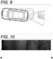
- Non Patent Literature 1 when two different locations are photographed with a camera installed at the rear of a vehicle, a plurality of images such as those shown in FIG. 10 are obtained.
- an optimal value of a homography matrix between the plurality of images is determined.
- an Efficient Second order Minimisation (ESM) algorithm is used for an algorithm for the iterative computation. Then, from the optimal value of the homography matrix, the amount of change in position and the amount of change in orientation of the vehicle are calculated.
- ESM Second order Minimisation
- the present disclosure is made in view of the above-described circumstances, and provides a map creation device, a map creation method, and a map creation program that can reduce the amount of iterative computation when calculating three-dimensional positions of features in a plurality of images obtained by photographing different locations.
- a map creation device includes: an image obtaining part that obtains a plurality of images from an in-vehicle camera that is mounted on a vehicle and photographs a surrounding of the vehicle, the plurality of images being obtained by photographing different locations; an odometry information calculating part that calculates odometry information indicating an amount of movement of the vehicle; an initial value calculating part that calculates an initial value of a homography matrix between the plurality of images from the odometry information of the vehicle; an optimal value calculating part that calculates, by iterative computation, an optimal value of the homography matrix from the initial value and a luminance value of each pixel included in a road-surface region specified in the plurality of images; a camera position and orientation calculating part that calculates an amount of change in camera position and an amount of change in camera orientation of the in-vehicle camera by resolving the optimal value; and a three-dimensional position calculating part that calculates three-
- a map creation device is such that in the map creation device according to the first aspect, the camera position and orientation calculating part further calculates an estimated value of a road surface's normal vector by resolving the optimal value, the road surface's normal vector being a vector in a normal direction of a road surface viewed from the in-vehicle camera, and the map creation device further includes a use determining part that determines to use the amount of change in camera position and the amount of change in camera orientation, when an error is less than a threshold value, the error being represented by an angle between the estimated value of the road surface's normal vector and a value of a road surface's normal vector that is determined in advance by calibration of the in-vehicle camera.
- a map creation device is such that in the map creation device according to the second aspect, the use determining part determines not to use the amount of change in camera position and the amount of change in camera orientation, when the error is greater than or equal to the threshold value.
- a map creation method includes: obtaining a plurality of images from an in-vehicle camera that is mounted on a vehicle and photographs a surrounding of the vehicle, the plurality of images being obtained by photographing different locations; calculating odometry information indicating an amount of movement of the vehicle; calculating an initial value of a homography matrix between the plurality of images from the odometry information of the vehicle; calculating, by iterative computation, an optimal value of the homography matrix from the initial value and a luminance value of each pixel included in a road-surface region specified in the plurality of images; calculating an amount of change in camera position and an amount of change in camera orientation of the in-vehicle camera by resolving the optimal value; and calculating three-dimensional positions of features in the plurality of images from the amount of change in camera position and the amount of change in camera orientation.
- a map creation program causes a computer to: obtain a plurality of images from an in-vehicle camera that is mounted on a vehicle and photographs a surrounding of the vehicle, the plurality of images being obtained by photographing different locations; calculate odometry information indicating an amount of movement of the vehicle; calculate an initial value of a homography matrix between the plurality of images from the odometry information of the vehicle; calculate, by iterative computation, an optimal value of the homography matrix from the initial value and a luminance value of each pixel included in a road-surface region specified in the plurality of images; calculate an amount of change in camera position and an amount of change in camera orientation of the in-vehicle camera by resolving the optimal value; and calculate three-dimensional positions of features in the plurality of images from the amount of change in camera position and the amount of change in camera orientation.
- a map creation device relates to initialization of a map performed when a point cloud map is created in a framework of a Visual Simultaneous Localization and Mapping (SLAM) technique that uses an in-vehicle camera.
- SLAM Visual Simultaneous Localization and Mapping
- the amount of change in position and the amount of change in orientation of the in-vehicle camera are determined from the luminance value of each pixel in a road-surface region.
- FIG. 1 is a diagram showing an example of a configuration of a map creation system 100 according to the present embodiment.
- the map creation system 100 includes a map creation device 10, a wheel speed sensor 20, a steering angle sensor 21, and an in-vehicle camera 22.
- the in-vehicle camera 22 is mounted on a vehicle and photographs surroundings of the vehicle. Where to install the in-vehicle camera 22 on the vehicle is not particularly limited as long as the in-vehicle camera 22 is installed to allow photographing of a road surface.
- the in-vehicle camera 22 for example, a monocular camera is applied, but the in-vehicle camera 22 is not limited thereto and a stereo camera, etc., may be used.
- the in-vehicle camera 22 is a monocular camera provided at the top of the vehicle, etc., and photographs surrounding areas such as in front of or behind the vehicle.
- the in-vehicle camera 22 is, for example, provided near a substantially central portion in a vehicle width direction and disposed such that an optical axis of the in-vehicle camera 22 faces slightly downward relative to a horizontal direction.
- the in-vehicle camera 22 is communicably connected to the map creation device 10, and sends photographed images to the map creation device 10.
- the wheel speed sensor 20 detects wheel speed of four wheels of the vehicle.
- the wheel speed sensor 20 sends the detected wheel speed to the map creation device 10.
- a wheel encoder is used, but for a vehicle including a motor such as a hybrid vehicle, a motor encoder may be used.
- the motor encoder has high detection accuracy compared to the wheel encoder and thus is desirable.
- the steering angle sensor 21 detects a steering angle of the vehicle.
- the steering angle sensor 21 sends the detected steering angle to the map creation device 10.
- the map creation device 10 calculates an initial value of a homography matrix between a plurality of images from odometry information of the vehicle, and calculates an optimal value of the homography matrix using the calculated initial value. By this, the amount of iterative computation can be reduced.
- the map creation device 10 according to the present embodiment is assumed for in-vehicle use. In a case of in-vehicle use, since the processing capabilities of resources such as a processor and a memory are relatively low, by reducing the amount of iterative computation, load on the resources decreases and thus a greater advantageous effect can be obtained.
- the map creation device 10 may be implemented as a part of an Electronic Control Unit (ECU) which is a computer for vehicle control, or may be implemented as an in-vehicle computer different from the ECU.
- ECU Electronic Control Unit
- the map creation device 10 includes a Central Processing Unit (CPU) 11, a Read Only Memory (ROM) 12, a Random Access Memory (RAM) 13, an input/output interface (I/O) 14, a storage part 15, and an external interface (external I/F) 16.
- CPU Central Processing Unit
- ROM Read Only Memory
- RAM Random Access Memory
- I/O input/output interface
- storage part storage part
- external I/F external interface
- the CPU 11, the ROM 12, the RAM 13, and the I/O 14 are connected to each other through a bus.
- Functional parts including the storage part 15 and the external I/F 16 are connected to the I/O 14. Each functional part can mutually communicate with the CPU 11 through the I/O 14.
- the CPU 11, the ROM 12, the RAM 13, and the I/O 14 form a control part.
- the control part may be formed as a sub-control part that controls a part of operation of the map creation device 10, or may be formed as a part of a main control part that controls the overall operation of the map creation device 10.
- an integrated circuit such as Large Scale Integration (LSI) or an Integrated Circuit (IC) chipset is used.
- LSI Large Scale Integration
- IC Integrated Circuit
- the storage part 15 for example, a Hard Disk Drive (HDD), a Solid State Drive (SSD), a flash memory, etc., are used.
- the storage part 15 stores therein a map creation program 15A according to the present embodiment. Note that the map creation program 15A may be stored in the ROM 12.
- the map creation program 15A may be, for example, installed in advance on the map creation device 10.
- the map creation program 15A may be implemented such that the map creation program 15A is stored in a non-volatile storage medium or distributed through a network, and installed on the map creation device 10 as appropriate.
- the non-volatile storage medium include a Compact Disc Read Only Memory (CD-ROM), a magneto-optical disk, an HDD, a Digital Versatile Disc Read Only Memory (DVD-ROM), a flash memory, and a memory card.
- the external I/F 16 is an interface for communicably establishing connection with each of the wheel speed sensor 20, the steering angle sensor 21, and the in-vehicle camera 22.
- the CPU 11 of the map creation device 10 functions as each part shown in FIG. 2 by writing the map creation program 15A stored in the storage part 15 into the RAM 13 and executing the map creation program 15A.
- FIG. 2 is a block diagram showing an example of a functional configuration of the map creation device 10 according to the present embodiment.
- the CPU 11 of the map creation device 10 functions as an image obtaining part 11A, a sensor information obtaining part 11B, an odometry information calculating part 11C, an initial value calculating part 11D, an optimal value calculating part 11E, a camera position and orientation calculating part 11F, a use determining part 11G, and a three-dimensional position calculating part 11H.
- the image obtaining part 11A obtains a plurality of images from the in-vehicle camera 22.
- the image obtaining part 11A sends the obtained plurality of images to the optimal value calculating part 11E.
- the plurality of images are, for example, images obtained by photographing two different locations.
- the sensor information obtaining part 11B obtains wheel speed detected by the wheel speed sensor 20 and a steering angle detected by the steering angle sensor 21.
- the sensor information obtaining part 11B sends the obtained wheel speed and steering angle to the odometry information calculating part 11C.
- the odometry information calculating part 11C calculates odometry information indicating the amount of movement of the vehicle, based on the wheel speed and steering angle sent from the sensor information obtaining part 11B. Specifically, the odometry information calculating part 11C calculates a distance traveled by the vehicle, based on the wheel speed and calculates a turning radius of the vehicle, based on the steering angle.
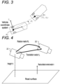
- FIG. 3 is a diagram showing an example of the amount of change in position and the amount of change in yaw angle of the vehicle according to the present embodiment.
- the odometry information calculating part 11C calculates the amount of change in position ( ⁇ X v , ⁇ Y v ) and the amount of change in yaw angle ⁇ v of the vehicle (reference point P1) in a vehicle coordinate system from a distance traveled by the vehicle and a turning radius of the vehicle.
- the odometry information calculating part 11C sends the calculated amount of change in position ( ⁇ X v , ⁇ Y v ) and amount of change in yaw angle ⁇ v , as odometry information of the vehicle, to the initial value calculating part 11D.
- the initial value calculating part 11D calculates an initial value of a homography matrix between the plurality of images, based on the odometry information of the vehicle sent from the odometry information calculating part 11C.
- a homography refers to projection of a plane to another plane using a projective transformation.
- the initial value calculating part 11D computes a translation vector t c representing a change in the position of the in-vehicle camera 22, from the amount of change in position ( ⁇ X v , ⁇ Y v ), and computes a rotation matrix R c representing a change in the orientation of the in-vehicle camera 22, from the amount of change in yaw angle ⁇ v .
- FIG. 4 is a diagram showing an example of a positional relationship between the in-vehicle camera 22 and a road surface according to the present embodiment.
- the in-vehicle camera 22 is installed at a height h from the road surface.
- the above-described amount of change in position ( ⁇ X v , ⁇ Y v ) and amount of change in yaw angle ⁇ v are calculated as odometry information.
- a translation vector t c is computed from the amount of change in position ( ⁇ X v , ⁇ Y v ), and a rotation matrix R c is computed from the amount of change in yaw angle ⁇ v .
- a road surface's normal vector n is a vector in a normal direction of the road surface viewed from the in-vehicle camera 22, and has a magnitude of 1.
- the initial value calculating part 11D calculates an initial value G 0 of a homography matrix using the following equation (1).
- G 0 K R c + t c n T / h K ⁇ 1
- K represents an internal parameter matrix of the in-vehicle camera 22
- R c represents the rotation matrix
- t c represents the translation vector
- n T represents a transposed matrix of the value n of the road surface's normal vector
- h represents the installation height of the in-vehicle camera 22 from the road surface. Note that for the internal parameter matrix K, the road surface's normal vector n, and the installation height h, values that are determined in advance by calibration of the in-vehicle camera 22 are used.
- the initial value calculating part 11D sends the initial value G 0 calculated using the above-described equation (1) to the optimal value calculating part 11E.
- the optimal value calculating part 11E calculates, by iterative computation, an optimal value of the homography matrix from the initial value sent from the initial value calculating part 11D and the luminance value of each pixel included in a road-surface region specified in the plurality of images sent from the image obtaining part 11A.
- an optimal value G OPT of a homography matrix is calculated using an ESM algorithm which is an example of iterative computation.
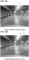
- FIGS. 5A and 5B are diagrams showing an example of corresponding road-surface regions between a plurality of images according to the present embodiment.
- FIG. 5A shows an image obtained before movement of the vehicle and
- FIG. 5B shows an image obtained after movement of the vehicle.
- a road-surface region R1 is specified.
- the image obtained after movement of the vehicle shown in FIG. 5B includes a road-surface region R2 computed using the initial value G 0 of the homography matrix and a road-surface region R3 computed using the optimal value G OPT of the homography matrix.
- an initial value G 0 of a homography matrix between images for two locations is calculated from odometry information of the vehicle, and an optimal value G OPT of the homography matrix is calculated using the calculated initial value G 0 . That is, by calculating the initial value G 0 of the homography matrix from the odometry information of the vehicle, the initial value G 0 is set to a value close to the optimal value G OPT , compared to a case of not using the odometry information. Hence, the number of iterations of iterative computation can be reduced. A specific method of calculating the optimal value G OPT of the homography matrix will be described later.
- the camera position and orientation calculating part 11F calculates the amount of change in camera position and the amount of change in camera orientation of the in-vehicle camera 22 by resolving the optimal value sent from the optimal value calculating part 11E.
- the amount of change in camera position is represented as an estimated value t est of the translation vector
- the amount of change in camera orientation is represented as an estimated value R est of the rotation matrix.
- the camera position and orientation calculating part 11F calculates an estimated value of the road surface's normal vector by resolving the optimal value sent from the optimal value calculating part 11E.
- the optimal value G OPT is resolved as shown in the following equation (2).
- G OPT K R est + t est n est T / h K ⁇ 1
- K represents the internal parameter matrix of the in-vehicle camera 22
- R est represents the rotation matrix (estimated value) representing the amount of change in camera orientation
- t est represents the translation vector (estimated value) representing the amount of change in camera position
- n est T represents the transposed matrix of the estimated value n est of the road surface's normal vector
- h represents the installation height of the in-vehicle camera 22 from the road surface.
- the use determining part 11G determines to use the amount of change in camera position and the amount of change in camera orientation in a subsequent process (i.e., a process of calculating three-dimensional positions), when an error which is represented by an angle between the estimated value n est of the road surface's normal vector and a value n of a road surface's normal vector which is determined in advance by calibration of the in-vehicle camera 22 is less than a threshold value.
- the use determining part 11G determines not to use the amount of change in camera position and the amount of change in camera orientation in the subsequent process.
- an optimal value of a homography matrix is determined again from a different set of images obtained by photographing two different locations.
- the threshold value can be set to an appropriate value in a range greater than 0 degrees and less than or equal to 5 degrees.
- the use determining part 11G is not essential and a configuration that does not include the use determining part 11G may be adopted. In this case, the amount of change in camera position and the amount of change in camera orientation that are calculated by the camera position and orientation calculating part 11F are used as they are in the subsequent process.
- the three-dimensional position calculating part 11H calculates three-dimensional positions of features in the plurality of images from the amount of change in camera position and the amount of change in camera orientation, when the use determining part 11G determines to use the amount of change in camera position and the amount of change in camera orientation. Specifically, the three-dimensional position calculating part 11H computes, using the principle of triangulation, three-dimensional positions of corresponding features between the images of two different locations from the positions of the features, the amount of change in camera position, and the amount of change in camera orientation.
- FIG. 6 is a flowchart showing an example of the flow of a process performed by the map creation program 15A according to the present embodiment.
- the CPU 11 starts the map creation program 15A, thereby performing the following steps.
- the CPU 11 obtains, from the in-vehicle camera 22, a plurality of images obtained by photographing two different locations.
- the CPU 11 obtains, as sensor information, each of wheel speed from the wheel speed sensor 20 and a steering angle from the steering angle sensor 21.
- the CPU 11 calculates odometry information indicating the amount of movement of the vehicle, based on the wheel speed and steering angle obtained at step S102. Specifically, the CPU 11 calculates a distance traveled by the vehicle, based on the wheel speed and calculates a turning radius of the vehicle, based on the steering angle. Then, the amount of change in position ( ⁇ X v , ⁇ Y v ) and the amount of change in yaw angle ⁇ v of the vehicle (reference point P1) in the vehicle coordinate system are calculated from the distance traveled by the vehicle and the turning radius of the vehicle.
- the CPU 11 calculates an initial value of a homography matrix between the plurality of images, based on the odometry information of the vehicle calculated at step S103. Specifically, as an example, as shown in the above-described FIG. 4 , the CPU 11 calculates a translation vector t c representing a change in the position of the in-vehicle camera 22 from the amount of change in position ( ⁇ X v , ⁇ Y v ), calculates a rotation matrix R c representing a change in the orientation of the in-vehicle camera 22 from the amount of change in yaw angle ⁇ v , and calculates an initial value G 0 of the homography matrix using the above-described equation (1).
- step S105 as an example, as shown in the above-described FIG. 5 , the CPU 11 calculates, by iterative computation, an optimal value of the homography matrix from the initial value calculated at step S104 and the luminance value of each pixel included in a road-surface region specified in the plurality of images obtained at step S101.
- a homography matrix's optimal value calculation process at step S105 will be specifically described.
- FIG. 7 is a flowchart showing an example of the flow of the homography matrix's optimal value calculation process according to the present embodiment, and shows a subroutine of step S105 of FIG. 6 .
- FIG. 8 is a diagram showing an example of an image I* obtained before movement and a tracking region.
- the CPU 11 specifies a tracking region (the same meaning as a road-surface region) in the image I* obtained before movement, and computes a luminance gradient matrix J I* and Jacobian matrices J W and J G .
- J I*ui represents the luminance gradient in a horizontal direction of an ith pixel
- J I*vi represents the luminance gradient in a vertical direction of the ith pixel
- Jw J w 1 J w 2 ⁇ J wn
- J wi p i * 0 ⁇ u i * p i * 0 p i * ⁇ ⁇ i * p i * 0 0 0
- J G A 1 V A 2 V ⁇ A 8 V
- [A i ] v is a vector of 9 rows by 1 column rearranged row by row.
- a 1 0 0 1 0 0 0 0 0 0 0
- a 2 0 0 0 0 1 0 0 0
- a 3 0 1 0 0 0 0 0 0 0
- a 4 0 0 0 1 0 0 0 0 0
- a 5 1 0 0 0 ⁇ 1 0 0 0 0 0
- a 6 0 0 0 ⁇ 1 0 0 0 1
- a 7 0 0 0 0 0 0 1 0 0
- a 8 0 0 0 0 0 0 0 1 0
- the CPU 11 substitutes the initial value G 0 for an estimated value G ⁇ ( ⁇ is above G; hereinafter, the same.) of the homography matrix, and substitutes 1 for the number of iterations n ite .
- the CPU 11 calculates a luminance gradient matrix J I for a tracking region in an image I obtained after movement.
- the luminance gradient matrix J I is computed from the luminance of each pixel in the tracking region in the image I obtained after movement, using the following equation.
- J 1 J I1 J J2 ⁇ J In
- J Iui represents the luminance gradient in a horizontal direction of an ith pixel
- J Ivi represents the luminance gradient in a vertical direction of the ith pixel
- the CPU 11 calculates a parameter x (a vector of 8 rows by 1 column) of the homography matrix.
- yi I i ⁇ I i ⁇
- the CPU 11 updates the estimated value G ⁇ of the homography matrix, using the following equation.
- a i G exp A x
- the CPU 11 determines whether or not a termination condition is satisfied, i.e., whether or not iteration is required. If it is determined that the termination condition is satisfied, i.e., iteration is not required (in a case of an affirmative determination), then the CPU 11 transitions to step S117. If it is determined that the termination condition is not satisfied, i.e., iteration is required (in a case of a negative determination), then the CPU 11 returns to step S113 and repeats processing.
- n max e.g., 100
- ⁇ e.g. 10 -5
- n ite 1
- the root mean square y curr of the luminance difference obtained this time is substituted for the root mean square y prev of a luminance difference obtained last time, and 1 is added to the number of iterations n ite , and processing returns to step S113.
- step S117 In a case of 1 ⁇ n ite ⁇ n max , if y prev - y curr > ⁇ , then it is determined that it is not converged, and thus, the root mean square y curr of the luminance difference obtained this time is substituted for the root mean square y prev of the luminance difference obtained last time, and 1 is added to the number of iterations n ite , and processing returns to step S113. On the other hand, if y prev - y curr ⁇ ⁇ , then it is determined that it is converged, and thus, processing transitions to step S117.
- the CPU 11 adopts the estimated value G ⁇ of the homography matrix as an optimal value G OPT , and returns to step S106 of FIG. 6 .
- the CPU 11 resolves the optimal value G OPT calculated at step S105, thereby calculating the amount of change in camera position, the amount of change in camera orientation, and an estimated value of a road surface's normal vector.
- the CPU 11 determines whether or not the amount of change in camera position and the amount of change in camera orientation can be used. If it is determined that the amount of change in camera position and the amount of change in camera orientation can be used (in a case of an affirmative determination), then the CPU 11 transitions to step S108. If it is determined that the amount of change in camera position and the amount of change in camera orientation cannot be used (in a case of a negative determination), then the CPU 11 returns to step S101 and repeats processing.
- the CPU 11 determines to use the amount of change in camera position and the amount of change in camera orientation in a subsequent process.
- the CPU 11 determines not to use the amount of change in camera position and the amount of change in camera orientation in the subsequent process.
- an optimal value of a homography matrix is determined again from a different set of images obtained by photographing two different locations.
- the CPU 11 calculates three-dimensional positions of features in the plurality of images from the amount of change in camera position and the amount of change in camera orientation, and terminates a series of processes performed by the map creation program 15A. Specifically, the CPU 11 computes, using the principle of triangulation, three-dimensional positions of corresponding features between the images of two different locations from the positions of the features, the amount of change in camera position, and the amount of change in camera orientation.
- an error in a homography matrix increases, and thus, an error in a normal line to the road surface determined from the homography matrix may also increase.
- the error in the normal line to the road surface is determined by comparison with a normal line to the road surface determined from camera installation orientation.
- the error in the normal line to the road surface is large, it is determined that the determined amount of change in camera position and amount of change in camera orientation cannot be used, and a homography matrix can be determined again from a different set of images obtained by photographing two locations.
- the processor indicates a processor in a broad sense and includes general-purpose processors (e.g., a CPU: Central Processing Unit) and dedicated processors (e.g., a GPU: Graphics Processing Unit, an ASIC: Application Specific Integrated Circuit, an FPGA: Field Programmable Gate Array, and a programmable logic device).
- general-purpose processors e.g., a CPU: Central Processing Unit
- dedicated processors e.g., a GPU: Graphics Processing Unit
- an ASIC Application Specific Integrated Circuit
- FPGA Field Programmable Gate Array
- programmable logic device e.g., a programmable logic device
- a processor in the above-described embodiments may not only be performed by one processor but also by a plurality of processors present at physically distant locations in a cooperative manner.
- the order in which various types of operation of the processor are performed is not limited to the one described in the above-described embodiments and may be changed as appropriate.
- a map creation device is exemplified and described above.
- the embodiment may be in the form of programs for causing a computer to perform a function of each part included in the map creation device.
- the embodiment may be in the form of a non-transient storage medium that can be read by a computer having the programs stored therein.
Landscapes
- Engineering & Computer Science (AREA)
- Physics & Mathematics (AREA)
- General Physics & Mathematics (AREA)
- Remote Sensing (AREA)
- Computer Vision & Pattern Recognition (AREA)
- Theoretical Computer Science (AREA)
- Radar, Positioning & Navigation (AREA)
- Multimedia (AREA)
- Automation & Control Theory (AREA)
- Image Analysis (AREA)
- Image Processing (AREA)
Abstract
Description
- The present disclosure relates to a map creation device, a map creation method, and a map creation program.
- Conventionally, there is a technique in which a surrounding environment is photographed with a camera mounted on a vehicle and the position and orientation of the vehicle are estimated from photographed images (e.g., Steven Lovegrove, Andrew J. Davison and Javier Ibanez-Guzman, "Accurate Visual Odometry from a Rear Parking Camera", Intelligent Vehicles Symposium, 2011.; hereinafter, referred to as "
Non Patent Literature 1".). - According to the technique described in
Non Patent Literature 1, as shown inFIG. 9 , when two different locations are photographed with a camera installed at the rear of a vehicle, a plurality of images such as those shown inFIG. 10 are obtained. By extracting a road-surface region from the plurality of images and performing iterative computation based on luminance of the extracted road-surface regions, an optimal value of a homography matrix between the plurality of images is determined. For an algorithm for the iterative computation, an Efficient Second order Minimisation (ESM) algorithm is used. Then, from the optimal value of the homography matrix, the amount of change in position and the amount of change in orientation of the vehicle are calculated. - However, in the technique described in the above-described
Non Patent Literature 1, the amount of iterative computation performed upon determining the optimal value of the homography matrix is large and thus a reduction in cost cannot be achieved. Hence, a reduction in the amount of iterative computation is sought. - The present disclosure is made in view of the above-described circumstances, and provides a map creation device, a map creation method, and a map creation program that can reduce the amount of iterative computation when calculating three-dimensional positions of features in a plurality of images obtained by photographing different locations.
- To provide the above-described map creation device, a map creation device according to a first aspect includes: an image obtaining part that obtains a plurality of images from an in-vehicle camera that is mounted on a vehicle and photographs a surrounding of the vehicle, the plurality of images being obtained by photographing different locations; an odometry information calculating part that calculates odometry information indicating an amount of movement of the vehicle; an initial value calculating part that calculates an initial value of a homography matrix between the plurality of images from the odometry information of the vehicle; an optimal value calculating part that calculates, by iterative computation, an optimal value of the homography matrix from the initial value and a luminance value of each pixel included in a road-surface region specified in the plurality of images; a camera position and orientation calculating part that calculates an amount of change in camera position and an amount of change in camera orientation of the in-vehicle camera by resolving the optimal value; and a three-dimensional position calculating part that calculates three-dimensional positions of features in the plurality of images from the amount of change in camera position and the amount of change in camera orientation.
- In addition, a map creation device according to a second aspect is such that in the map creation device according to the first aspect, the camera position and orientation calculating part further calculates an estimated value of a road surface's normal vector by resolving the optimal value, the road surface's normal vector being a vector in a normal direction of a road surface viewed from the in-vehicle camera, and the map creation device further includes a use determining part that determines to use the amount of change in camera position and the amount of change in camera orientation, when an error is less than a threshold value, the error being represented by an angle between the estimated value of the road surface's normal vector and a value of a road surface's normal vector that is determined in advance by calibration of the in-vehicle camera.
- In addition, a map creation device according to a third aspect is such that in the map creation device according to the second aspect, the use determining part determines not to use the amount of change in camera position and the amount of change in camera orientation, when the error is greater than or equal to the threshold value.
- Furthermore, to provide the above-described map creation method, a map creation method according to a fourth aspect includes: obtaining a plurality of images from an in-vehicle camera that is mounted on a vehicle and photographs a surrounding of the vehicle, the plurality of images being obtained by photographing different locations; calculating odometry information indicating an amount of movement of the vehicle; calculating an initial value of a homography matrix between the plurality of images from the odometry information of the vehicle; calculating, by iterative computation, an optimal value of the homography matrix from the initial value and a luminance value of each pixel included in a road-surface region specified in the plurality of images; calculating an amount of change in camera position and an amount of change in camera orientation of the in-vehicle camera by resolving the optimal value; and calculating three-dimensional positions of features in the plurality of images from the amount of change in camera position and the amount of change in camera orientation.
- Furthermore, to provide the above-described map creation program, a map creation program according to a fifth aspect causes a computer to: obtain a plurality of images from an in-vehicle camera that is mounted on a vehicle and photographs a surrounding of the vehicle, the plurality of images being obtained by photographing different locations; calculate odometry information indicating an amount of movement of the vehicle; calculate an initial value of a homography matrix between the plurality of images from the odometry information of the vehicle; calculate, by iterative computation, an optimal value of the homography matrix from the initial value and a luminance value of each pixel included in a road-surface region specified in the plurality of images; calculate an amount of change in camera position and an amount of change in camera orientation of the in-vehicle camera by resolving the optimal value; and calculate three-dimensional positions of features in the plurality of images from the amount of change in camera position and the amount of change in camera orientation.
- According to a technique of the present disclosure, there is an advantageous effect that when three-dimensional positions of features in a plurality of images obtained by photographing different locations are calculated, the amount of iterative computation can be reduced.
-
-
FIG. 1 is a diagram showing an example of a configuration of a map creation system according to an embodiment. -
FIG. 2 is a block diagram showing an example of a functional configuration of a map creation device according to the embodiment. -
FIG. 3 is a diagram showing an example of the amount of change in position and the amount of change in yaw angle of a vehicle according to the embodiment. -
FIG. 4 is a diagram showing an example of a positional relationship between an in-vehicle camera and a road surface according to the embodiment. -
FIG. 5A is a diagram showing an example of a corresponding road-surface region between a plurality of images and showing an image obtained before movement of the vehicle, according to the embodiment. -
FIG. 5B is a diagram showing an example of a corresponding road-surface region between the plurality of images and showing an image obtained after movement of the vehicle, according to the embodiment. -
FIG. 6 is a flowchart showing an example of the flow of a process performed by a map creation program according to the embodiment. -
FIG. 7 is a flowchart showing an example of the flow of a homography matrix's optimal value calculation process according to the embodiment. -
FIG. 8 is a diagram showing an example of an image obtained before movement and a tracking region. -
FIG. 9 is a diagram provided to describe conventional art. -
FIG. 10 is a diagram provided to describe the conventional art. - An example of a mode for carrying out a technique of the present disclosure will be described in detail below with reference to the drawings. Note that components and processes that have the same operation, action, or functions are given the same reference signs throughout all drawings, and an overlapping description thereof may be omitted as appropriate. Each drawing is merely schematically shown to the extent that the technique of the present disclosure can be adequately understood. Thus, the technique of the present disclosure is not limited only to examples shown in the drawings. In addition, in the present embodiment, a description of configurations that are not directly related to the technique of the present disclosure or well-known configurations may be omitted.
- A map creation device according to the present embodiment relates to initialization of a map performed when a point cloud map is created in a framework of a Visual Simultaneous Localization and Mapping (SLAM) technique that uses an in-vehicle camera. In the initialization of a map, first, there is a need to determine the amount of change in position and the amount of change in orientation of the in-vehicle camera from images obtained by photographing two different locations. However, in a scene with a very few features that can be detected from images, it is difficult to accurately determine the amount of change in position and the amount of change in orientation of the in-vehicle camera from the features. Hence, the amount of change in position and the amount of change in orientation of the in-vehicle camera are determined from the luminance value of each pixel in a road-surface region.
-
FIG. 1 is a diagram showing an example of a configuration of amap creation system 100 according to the present embodiment. - As shown in
FIG. 1 , themap creation system 100 according to the present embodiment includes amap creation device 10, awheel speed sensor 20, asteering angle sensor 21, and an in-vehicle camera 22. - The in-
vehicle camera 22 is mounted on a vehicle and photographs surroundings of the vehicle. Where to install the in-vehicle camera 22 on the vehicle is not particularly limited as long as the in-vehicle camera 22 is installed to allow photographing of a road surface. For the in-vehicle camera 22, for example, a monocular camera is applied, but the in-vehicle camera 22 is not limited thereto and a stereo camera, etc., may be used. - Specifically, the in-
vehicle camera 22 is a monocular camera provided at the top of the vehicle, etc., and photographs surrounding areas such as in front of or behind the vehicle. The in-vehicle camera 22 is, for example, provided near a substantially central portion in a vehicle width direction and disposed such that an optical axis of the in-vehicle camera 22 faces slightly downward relative to a horizontal direction. The in-vehicle camera 22 is communicably connected to themap creation device 10, and sends photographed images to themap creation device 10. - The
wheel speed sensor 20 detects wheel speed of four wheels of the vehicle. Thewheel speed sensor 20 sends the detected wheel speed to themap creation device 10. For thewheel speed sensor 20, normally, a wheel encoder is used, but for a vehicle including a motor such as a hybrid vehicle, a motor encoder may be used. The motor encoder has high detection accuracy compared to the wheel encoder and thus is desirable. - The
steering angle sensor 21 detects a steering angle of the vehicle. Thesteering angle sensor 21 sends the detected steering angle to themap creation device 10. - The
map creation device 10 according to the present embodiment calculates an initial value of a homography matrix between a plurality of images from odometry information of the vehicle, and calculates an optimal value of the homography matrix using the calculated initial value. By this, the amount of iterative computation can be reduced. Themap creation device 10 according to the present embodiment is assumed for in-vehicle use. In a case of in-vehicle use, since the processing capabilities of resources such as a processor and a memory are relatively low, by reducing the amount of iterative computation, load on the resources decreases and thus a greater advantageous effect can be obtained. - Specifically, the
map creation device 10 may be implemented as a part of an Electronic Control Unit (ECU) which is a computer for vehicle control, or may be implemented as an in-vehicle computer different from the ECU. - The
map creation device 10 includes a Central Processing Unit (CPU) 11, a Read Only Memory (ROM) 12, a Random Access Memory (RAM) 13, an input/output interface (I/O) 14, astorage part 15, and an external interface (external I/F) 16. - The
CPU 11, theROM 12, theRAM 13, and the I/O 14 are connected to each other through a bus. Functional parts including thestorage part 15 and the external I/F 16 are connected to the I/O 14. Each functional part can mutually communicate with theCPU 11 through the I/O 14. - The
CPU 11, theROM 12, theRAM 13, and the I/O 14 form a control part. The control part may be formed as a sub-control part that controls a part of operation of themap creation device 10, or may be formed as a part of a main control part that controls the overall operation of themap creation device 10. For some or all of blocks of the control part, for example, an integrated circuit such as Large Scale Integration (LSI) or an Integrated Circuit (IC) chipset is used. For the above-described blocks, individual circuits may be used or a partially or fully integrated circuit may be used. All blocks may be provided in a one-piece design or some blocks may be provided separately. In addition, for each block, a part of the block may be provided separately. Integration of the control part is not limited to LSI, and a dedicated circuit or a general-purpose processor may be used. - For the
storage part 15, for example, a Hard Disk Drive (HDD), a Solid State Drive (SSD), a flash memory, etc., are used. Thestorage part 15 stores therein amap creation program 15A according to the present embodiment. Note that themap creation program 15A may be stored in theROM 12. - The map creation program 15Amay be, for example, installed in advance on the
map creation device 10. Themap creation program 15A may be implemented such that themap creation program 15A is stored in a non-volatile storage medium or distributed through a network, and installed on themap creation device 10 as appropriate. Note that possible examples of the non-volatile storage medium include a Compact Disc Read Only Memory (CD-ROM), a magneto-optical disk, an HDD, a Digital Versatile Disc Read Only Memory (DVD-ROM), a flash memory, and a memory card. - The external I/
F 16 is an interface for communicably establishing connection with each of thewheel speed sensor 20, thesteering angle sensor 21, and the in-vehicle camera 22. - The
CPU 11 of themap creation device 10 according to the present embodiment functions as each part shown inFIG. 2 by writing themap creation program 15A stored in thestorage part 15 into theRAM 13 and executing themap creation program 15A. -
FIG. 2 is a block diagram showing an example of a functional configuration of themap creation device 10 according to the present embodiment. - As shown in
FIG. 2 , theCPU 11 of themap creation device 10 according to the present embodiment functions as animage obtaining part 11A, a sensorinformation obtaining part 11B, an odometry information calculating part 11C, an initial value calculating part 11D, an optimalvalue calculating part 11E, a camera position andorientation calculating part 11F, ause determining part 11G, and a three-dimensionalposition calculating part 11H. - The
image obtaining part 11A obtains a plurality of images from the in-vehicle camera 22. Theimage obtaining part 11A sends the obtained plurality of images to the optimalvalue calculating part 11E. The plurality of images are, for example, images obtained by photographing two different locations. - The sensor
information obtaining part 11B obtains wheel speed detected by thewheel speed sensor 20 and a steering angle detected by thesteering angle sensor 21. The sensorinformation obtaining part 11B sends the obtained wheel speed and steering angle to the odometry information calculating part 11C. - The odometry information calculating part 11C calculates odometry information indicating the amount of movement of the vehicle, based on the wheel speed and steering angle sent from the sensor
information obtaining part 11B. Specifically, the odometry information calculating part 11C calculates a distance traveled by the vehicle, based on the wheel speed and calculates a turning radius of the vehicle, based on the steering angle. -
FIG. 3 is a diagram showing an example of the amount of change in position and the amount of change in yaw angle of the vehicle according to the present embodiment. - As shown in
FIG. 3 , the odometry information calculating part 11C calculates the amount of change in position (ΔXv, ΔYv) and the amount of change in yaw angle Δθv of the vehicle (reference point P1) in a vehicle coordinate system from a distance traveled by the vehicle and a turning radius of the vehicle. The odometry information calculating part 11C sends the calculated amount of change in position (ΔXv, ΔYv) and amount of change in yaw angle Δθv, as odometry information of the vehicle, to the initial value calculating part 11D. - The initial value calculating part 11D calculates an initial value of a homography matrix between the plurality of images, based on the odometry information of the vehicle sent from the odometry information calculating part 11C. Note that a homography refers to projection of a plane to another plane using a projective transformation. Specifically, the initial value calculating part 11D computes a translation vector tc representing a change in the position of the in-
vehicle camera 22, from the amount of change in position (ΔXv, ΔYv), and computes a rotation matrix Rc representing a change in the orientation of the in-vehicle camera 22, from the amount of change in yaw angle Δθv. -
FIG. 4 is a diagram showing an example of a positional relationship between the in-vehicle camera 22 and a road surface according to the present embodiment. - As shown in
FIG. 4 , the in-vehicle camera 22 is installed at a height h from the road surface. When the vehicle has moved from a location to another location, the above-described amount of change in position (ΔXv, ΔYv) and amount of change in yaw angle Δθv are calculated as odometry information. Then, a translation vector tc is computed from the amount of change in position (ΔXv, ΔYv), and a rotation matrix Rc is computed from the amount of change in yaw angle Δθv. A road surface's normal vector n is a vector in a normal direction of the road surface viewed from the in-vehicle camera 22, and has a magnitude of 1. - The initial value calculating part 11D calculates an initial value G0 of a homography matrix using the following equation (1).

- Note that K represents an internal parameter matrix of the in-
vehicle camera 22, and Rc represents the rotation matrix. tc represents the translation vector, nT represents a transposed matrix of the value n of the road surface's normal vector, and h represents the installation height of the in-vehicle camera 22 from the road surface. Note that for the internal parameter matrix K, the road surface's normal vector n, and the installation height h, values that are determined in advance by calibration of the in-vehicle camera 22 are used. - The initial value calculating part 11D sends the initial value G0 calculated using the above-described equation (1) to the optimal
value calculating part 11E. - The optimal
value calculating part 11E calculates, by iterative computation, an optimal value of the homography matrix from the initial value sent from the initial value calculating part 11D and the luminance value of each pixel included in a road-surface region specified in the plurality of images sent from theimage obtaining part 11A. Specifically, as an example, as shown inFIG. 5 , a road-surface region is specified in an image, and an optimal value GOPT of a homography matrix is calculated using an ESM algorithm which is an example of iterative computation. -
FIGS. 5A and 5B are diagrams showing an example of corresponding road-surface regions between a plurality of images according to the present embodiment.FIG. 5A shows an image obtained before movement of the vehicle andFIG. 5B shows an image obtained after movement of the vehicle. - In the image obtained before movement of the vehicle shown in
FIG. 5A , a road-surface region R1 is specified. The image obtained after movement of the vehicle shown inFIG. 5B includes a road-surface region R2 computed using the initial value G0 of the homography matrix and a road-surface region R3 computed using the optimal value GOPT of the homography matrix. - According to the example of
FIGS. 5A and 5B , an initial value G0 of a homography matrix between images for two locations is calculated from odometry information of the vehicle, and an optimal value GOPT of the homography matrix is calculated using the calculated initial value G0. That is, by calculating the initial value G0 of the homography matrix from the odometry information of the vehicle, the initial value G0 is set to a value close to the optimal value GOPT, compared to a case of not using the odometry information. Hence, the number of iterations of iterative computation can be reduced. A specific method of calculating the optimal value GOPT of the homography matrix will be described later. - The camera position and
orientation calculating part 11F calculates the amount of change in camera position and the amount of change in camera orientation of the in-vehicle camera 22 by resolving the optimal value sent from the optimalvalue calculating part 11E. The amount of change in camera position is represented as an estimated value test of the translation vector, and the amount of change in camera orientation is represented as an estimated value Rest of the rotation matrix. In addition, the camera position andorientation calculating part 11F calculates an estimated value of the road surface's normal vector by resolving the optimal value sent from the optimalvalue calculating part 11E. Specifically, the optimal value GOPT is resolved as shown in the following equation (2).
- Note that K represents the internal parameter matrix of the in-
vehicle camera 22, and Rest represents the rotation matrix (estimated value) representing the amount of change in camera orientation. test represents the translation vector (estimated value) representing the amount of change in camera position, nest T represents the transposed matrix of the estimated value nest of the road surface's normal vector, and h represents the installation height of the in-vehicle camera 22 from the road surface. - The
use determining part 11G determines to use the amount of change in camera position and the amount of change in camera orientation in a subsequent process (i.e., a process of calculating three-dimensional positions), when an error which is represented by an angle between the estimated value nest of the road surface's normal vector and a value n of a road surface's normal vector which is determined in advance by calibration of the in-vehicle camera 22 is less than a threshold value. On the other hand, when the error is greater than or equal to the threshold value, theuse determining part 11G determines not to use the amount of change in camera position and the amount of change in camera orientation in the subsequent process. When the amount of change in camera position and the amount of change in camera orientation are not used, an optimal value of a homography matrix is determined again from a different set of images obtained by photographing two different locations. The threshold value can be set to an appropriate value in a range greater than 0 degrees and less than or equal to 5 degrees. Note that theuse determining part 11G is not essential and a configuration that does not include theuse determining part 11G may be adopted. In this case, the amount of change in camera position and the amount of change in camera orientation that are calculated by the camera position andorientation calculating part 11F are used as they are in the subsequent process. - The three-dimensional
position calculating part 11H calculates three-dimensional positions of features in the plurality of images from the amount of change in camera position and the amount of change in camera orientation, when theuse determining part 11G determines to use the amount of change in camera position and the amount of change in camera orientation. Specifically, the three-dimensionalposition calculating part 11H computes, using the principle of triangulation, three-dimensional positions of corresponding features between the images of two different locations from the positions of the features, the amount of change in camera position, and the amount of change in camera orientation. - Next, with reference to
FIG. 6 , action of themap creation device 10 according to the present embodiment will be described. -
FIG. 6 is a flowchart showing an example of the flow of a process performed by themap creation program 15A according to the present embodiment. - First, when the
map creation device 10 accepts an instruction to start a map creation process, theCPU 11 starts themap creation program 15A, thereby performing the following steps. - At step S101 of
FIG. 6 , as an example, as shown in the above-describedFIG. 5 , theCPU 11 obtains, from the in-vehicle camera 22, a plurality of images obtained by photographing two different locations. - At step S102, the
CPU 11 obtains, as sensor information, each of wheel speed from thewheel speed sensor 20 and a steering angle from thesteering angle sensor 21. - At step S103, as an example, as shown in the above-described
FIG. 3 , theCPU 11 calculates odometry information indicating the amount of movement of the vehicle, based on the wheel speed and steering angle obtained at step S102. Specifically, theCPU 11 calculates a distance traveled by the vehicle, based on the wheel speed and calculates a turning radius of the vehicle, based on the steering angle. Then, the amount of change in position (ΔXv, ΔYv) and the amount of change in yaw angle Δθv of the vehicle (reference point P1) in the vehicle coordinate system are calculated from the distance traveled by the vehicle and the turning radius of the vehicle. - At step S104, the
CPU 11 calculates an initial value of a homography matrix between the plurality of images, based on the odometry information of the vehicle calculated at step S103. Specifically, as an example, as shown in the above-describedFIG. 4 , theCPU 11 calculates a translation vector tc representing a change in the position of the in-vehicle camera 22 from the amount of change in position (ΔXv, ΔYv), calculates a rotation matrix Rc representing a change in the orientation of the in-vehicle camera 22 from the amount of change in yaw angle Δθv, and calculates an initial value G0 of the homography matrix using the above-described equation (1). - At step S105, as an example, as shown in the above-described
FIG. 5 , theCPU 11 calculates, by iterative computation, an optimal value of the homography matrix from the initial value calculated at step S104 and the luminance value of each pixel included in a road-surface region specified in the plurality of images obtained at step S101. Here, with reference toFIGS. 7 and 8 , a homography matrix's optimal value calculation process at step S105 will be specifically described. -
FIG. 7 is a flowchart showing an example of the flow of the homography matrix's optimal value calculation process according to the present embodiment, and shows a subroutine of step S105 ofFIG. 6 . In addition,FIG. 8 is a diagram showing an example of an image I* obtained before movement and a tracking region. - At step S111 of
FIG. 7 , as an example, as shown inFIG. 8 , theCPU 11 specifies a tracking region (the same meaning as a road-surface region) in the image I* obtained before movement, and computes a luminance gradient matrix JI* and Jacobian matrices JW and JG. - Specifically, as shown in
FIG. 8 , the number of pixels in the tracking region is n (= nu × nv). The luminance gradient matrix JI* is computed from the luminance (the values of 0 to 255) of each pixel in the tracking region in the image I* obtained before movement, using the following equation.
- Note that

- JI*ui represents the luminance gradient in a horizontal direction of an ith pixel, and JI*vi represents the luminance gradient in a vertical direction of the ith pixel.
- The Jacobian matrix Jw is computed from the coordinates of each pixel in the tracking region in the image I* obtained before movement, using the following equation.

- Note that the coordinates of each pixel in the tracking region are represented by

- In this case,

- The Jacobian matrix JG is computed from a basis Ai (i = 1 to 8) of a Lie algebra, using the following equation.

- In the equation, [Ai]v is a vector of 9 rows by 1 column rearranged row by row.

- At step S112, the
CPU 11 substitutes the initial value G0 for an estimated value G^ (^ is above G; hereinafter, the same.) of the homography matrix, and substitutes 1 for the number of iterations nite. - At step S113, the
CPU 11 calculates a luminance gradient matrix JI for a tracking region in an image I obtained after movement. - Specifically, coordinates in the image I obtained after movement are computed using the following equation.

- Note that the coordinates in the image I obtained after movement are represented by

- The luminance gradient matrix JI is computed from the luminance of each pixel in the tracking region in the image I obtained after movement, using the following equation.

- Note that

- JIui represents the luminance gradient in a horizontal direction of an ith pixel, and JIvi represents the luminance gradient in a vertical direction of the ith pixel.
- At
step S 114, theCPU 11 calculates a parameter x (a vector of 8 rows by 1 column) of the homography matrix. - Specifically, the parameter x is computed using the following equation.

- In the equation, Jesm is a Jacobian matrix and is computed using the following equation.

- On the other hand, y is a luminance difference vector and is represented by the following equation.

- In the equation, yi is computed from the luminance Ii of the ith pixel obtained after movement and the luminance Ii* of the ith pixel obtained before movement, using the following equation.

- At
step S 115, theCPU 11 updates the estimated value G^ of the homography matrix, using the following equation.

- The above-described G is used as a new G^.
- At step S116, the
CPU 11 determines whether or not a termination condition is satisfied, i.e., whether or not iteration is required. If it is determined that the termination condition is satisfied, i.e., iteration is not required (in a case of an affirmative determination), then theCPU 11 transitions to step S117. If it is determined that the termination condition is not satisfied, i.e., iteration is required (in a case of a negative determination), then theCPU 11 returns to step S113 and repeats processing. - Specifically, when the root mean square of a luminance difference obtained this time is ycurr, ycurr is represented by the following equation.

- The maximum number of iterations is nmax (e.g., 100) and a threshold value for convergence determination is ε (e.g., 10-5).
- In a case of nite = 1, the root mean square ycurr of the luminance difference obtained this time is substituted for the root mean square yprev of a luminance difference obtained last time, and 1 is added to the number of iterations nite, and processing returns to step S113.
- In a case of 1 < nite < nmax, if yprev - ycurr > ε, then it is determined that it is not converged, and thus, the root mean square ycurr of the luminance difference obtained this time is substituted for the root mean square yprev of the luminance difference obtained last time, and 1 is added to the number of iterations nite, and processing returns to step S113. On the other hand, if yprev - ycurr ≤ ε, then it is determined that it is converged, and thus, processing transitions to step S117.
- In a case of nite = nmax, processing transitions to step S117.
- At step S117, the
CPU 11 adopts the estimated value G^ of the homography matrix as an optimal value GOPT, and returns to step S106 ofFIG. 6 . - Referring back to
FIG. 6 , at step S106, as an example, using the above-described equation (2), theCPU 11 resolves the optimal value GOPT calculated at step S105, thereby calculating the amount of change in camera position, the amount of change in camera orientation, and an estimated value of a road surface's normal vector. - At step S107, the
CPU 11 determines whether or not the amount of change in camera position and the amount of change in camera orientation can be used. If it is determined that the amount of change in camera position and the amount of change in camera orientation can be used (in a case of an affirmative determination), then theCPU 11 transitions to step S108. If it is determined that the amount of change in camera position and the amount of change in camera orientation cannot be used (in a case of a negative determination), then theCPU 11 returns to step S101 and repeats processing. Specifically, when an error which is represented by an angle between the estimated value nest of the road surface's normal vector and a value n of a road surface's normal vector which is determined in advance by calibration of the in-vehicle camera 22 is less than a threshold value, theCPU 11 determines to use the amount of change in camera position and the amount of change in camera orientation in a subsequent process. On the other hand, when the error is greater than or equal to the threshold value, theCPU 11 determines not to use the amount of change in camera position and the amount of change in camera orientation in the subsequent process. When the amount of change in camera position and the amount of change in camera orientation are not used, an optimal value of a homography matrix is determined again from a different set of images obtained by photographing two different locations. - At step S108, the
CPU 11 calculates three-dimensional positions of features in the plurality of images from the amount of change in camera position and the amount of change in camera orientation, and terminates a series of processes performed by themap creation program 15A. Specifically, theCPU 11 computes, using the principle of triangulation, three-dimensional positions of corresponding features between the images of two different locations from the positions of the features, the amount of change in camera position, and the amount of change in camera orientation. - Thus, according to the present embodiment, by calculating an initial value of a homography matrix from odometry information of the vehicle, iterative computation can be started with a value close to an optimal value of the homography matrix. Hence, the number of iterations of iterative computation is reduced.
- In addition, when the texture (pattern) of a road surface is poor, an error in a homography matrix increases, and thus, an error in a normal line to the road surface determined from the homography matrix may also increase. The error in the normal line to the road surface is determined by comparison with a normal line to the road surface determined from camera installation orientation. When the error in the normal line to the road surface is large, it is determined that the determined amount of change in camera position and amount of change in camera orientation cannot be used, and a homography matrix can be determined again from a different set of images obtained by photographing two locations.
- Note that, in the above-described embodiments, the processor indicates a processor in a broad sense and includes general-purpose processors (e.g., a CPU: Central Processing Unit) and dedicated processors (e.g., a GPU: Graphics Processing Unit, an ASIC: Application Specific Integrated Circuit, an FPGA: Field Programmable Gate Array, and a programmable logic device).
- In addition, the operation of a processor in the above-described embodiments may not only be performed by one processor but also by a plurality of processors present at physically distant locations in a cooperative manner. In addition, the order in which various types of operation of the processor are performed is not limited to the one described in the above-described embodiments and may be changed as appropriate.
- A map creation device according to the embodiment is exemplified and described above. The embodiment may be in the form of programs for causing a computer to perform a function of each part included in the map creation device. The embodiment may be in the form of a non-transient storage medium that can be read by a computer having the programs stored therein.
- In addition to the above, the configuration of the map creation device described in the above-described embodiment is an example and may be changed according to the situation, without departing from the true spirit.
- In addition, the flow of a process performed by the program which is described in the above-described embodiment is also an example, and an unnecessary step may be deleted or a new step may be added or the processing order may be changed without departing from the true spirit.
- In addition, although the above-described embodiment describes a case in which by executing the program, processes according to the embodiment are implemented by a software configuration using a computer, the embodiment is not limited thereto. The embodiment may be implemented, for example, by a hardware configuration or a combination of a hardware configuration and a software configuration.
- The disclosure of
Japanese Patent Application No. 2021-178338 filed October 29, 2021
Claims (5)
- A map creation device comprising:an image obtaining part that obtains a plurality of images from an in-vehicle camera that is mounted on a vehicle and photographs a surrounding of the vehicle, the plurality of images being obtained by photographing different locations;an odometry information calculating part that calculates odometry information indicating an amount of movement of the vehicle;an initial value calculating part that calculates an initial value of a homography matrix between the plurality of images from the odometry information of the vehicle;an optimal value calculating part that calculates, by iterative computation, an optimal value of the homography matrix from the initial value and a luminance value of each pixel included in a road-surface region specified in the plurality of images;a camera position and orientation calculating part that calculates an amount of change in camera position and an amount of change in camera orientation of the in-vehicle camera by resolving the optimal value; anda three-dimensional position calculating part that calculates three-dimensional positions of features in the plurality of images from the amount of change in camera position and the amount of change in camera orientation.
- The map creation device according to claim 1, whereinthe camera position and orientation calculating part further calculates an estimated value of a road surface's normal vector by resolving the optimal value, the road surface's normal vector being a vector in a normal direction of a road surface viewed from the in-vehicle camera, andthe map creation device further comprises a use determining part that determines to use the amount of change in camera position and the amount of change in camera orientation, when an error is less than a threshold value, the error being represented by an angle between the estimated value of the road surface's normal vector and a value of a road surface's normal vector that is determined in advance by calibration of the in-vehicle camera.
- The map creation device according to claim 2, wherein the use determining part determines not to use the amount of change in camera position and the amount of change in camera orientation, when the error is greater than or equal to the threshold value.
- A map creation method comprising:obtaining a plurality of images from an in-vehicle camera that is mounted on a vehicle and photographs a surrounding of the vehicle, the plurality of images being obtained by photographing different locations;calculating odometry information indicating an amount of movement of the vehicle;calculating an initial value of a homography matrix between the plurality of images from the odometry information of the vehicle;calculating, by iterative computation, an optimal value of the homography matrix from the initial value and a luminance value of each pixel included in a road-surface region specified in the plurality of images;calculating an amount of change in camera position and an amount of change in camera orientation of the in-vehicle camera by resolving the optimal value; andcalculating three-dimensional positions of features in the plurality of images from the amount of change in camera position and the amount of change in camera orientation.
- A map creation program for causing a computer to:obtain a plurality of images from an in-vehicle camera that is mounted on a vehicle and photographs a surrounding of the vehicle, the plurality of images being obtained by photographing different locations;calculate odometry information indicating an amount of movement of the vehicle;calculate an initial value of a homography matrix between the plurality of images from the odometry information of the vehicle;calculate, by iterative computation, an optimal value of the homography matrix from the initial value and a luminance value of each pixel included in a road-surface region specified in the plurality of images;calculate an amount of change in camera position and an amount of change in camera orientation of the in-vehicle camera by resolving the optimal value; andcalculate three-dimensional positions of features in the plurality of images from the amount of change in camera position and the amount of change in camera orientation.
Applications Claiming Priority (2)
| Application Number | Priority Date | Filing Date | Title |
|---|---|---|---|
| JP2021178338A JP7714436B2 (en) | 2021-10-29 | 2021-10-29 | Map creation device, map creation method, and map creation program |
| PCT/JP2022/040838 WO2023074907A1 (en) | 2021-10-29 | 2022-10-31 | Map creation device, map creation method, and map creation program |
Publications (2)
| Publication Number | Publication Date |
|---|---|
| EP4425430A1 true EP4425430A1 (en) | 2024-09-04 |
| EP4425430A4 EP4425430A4 (en) | 2025-02-12 |
Family
ID=86158106
Family Applications (1)
| Application Number | Title | Priority Date | Filing Date |
|---|---|---|---|
| EP22887232.1A Pending EP4425430A4 (en) | 2021-10-29 | 2022-10-31 | Map creation device, map creation method, and map creation program |
Country Status (5)
| Country | Link |
|---|---|
| US (1) | US20240386598A1 (en) |
| EP (1) | EP4425430A4 (en) |
| JP (1) | JP7714436B2 (en) |
| CN (1) | CN117957569A (en) |
| WO (1) | WO2023074907A1 (en) |
Families Citing this family (3)
| Publication number | Priority date | Publication date | Assignee | Title |
|---|---|---|---|---|
| KR20230158335A (en) * | 2022-05-11 | 2023-11-20 | 현대자동차주식회사 | Vehicle and control method thereof |
| US12482128B2 (en) * | 2022-08-17 | 2025-11-25 | Gm Cruise Holdings Llc | Identifying stability of an object based on surface normal vectors |
| JP2025154751A (en) * | 2024-03-29 | 2025-10-10 | オムロン株式会社 | Odometry parameter calibration device, method, and program |
Family Cites Families (2)
| Publication number | Priority date | Publication date | Assignee | Title |
|---|---|---|---|---|
| JP6192507B2 (en) | 2013-11-20 | 2017-09-06 | キヤノン株式会社 | Image processing apparatus, control method thereof, control program, and imaging apparatus |
| JP7507599B2 (en) | 2020-05-12 | 2024-06-28 | 株式会社ディスコ | Laser processing method |
-
2021
- 2021-10-29 JP JP2021178338A patent/JP7714436B2/en active Active
-
2022
- 2022-10-31 WO PCT/JP2022/040838 patent/WO2023074907A1/en not_active Ceased
- 2022-10-31 US US18/691,587 patent/US20240386598A1/en active Pending
- 2022-10-31 CN CN202280063240.9A patent/CN117957569A/en active Pending
- 2022-10-31 EP EP22887232.1A patent/EP4425430A4/en active Pending
Also Published As
| Publication number | Publication date |
|---|---|
| EP4425430A4 (en) | 2025-02-12 |
| WO2023074907A1 (en) | 2023-05-04 |
| CN117957569A (en) | 2024-04-30 |
| US20240386598A1 (en) | 2024-11-21 |
| JP2023067265A (en) | 2023-05-16 |
| JP7714436B2 (en) | 2025-07-29 |
Similar Documents
| Publication | Publication Date | Title |
|---|---|---|
| US11288833B2 (en) | Distance estimation apparatus and operating method thereof | |
| US20240386598A1 (en) | Map creation device, map creation method, and map creation program | |
| EP3673233B1 (en) | Vehicle environment modeling with a camera | |
| CN112183241A (en) | Method and device for target detection based on monocular image | |
| CN110979313B (en) | Automatic parking positioning method and system based on space map | |
| CN112219225B (en) | Positioning method, system and movable platform | |
| US11620831B2 (en) | Register sets of low-level features without data association | |
| US10657396B1 (en) | Method and device for estimating passenger statuses in 2 dimension image shot by using 2 dimension camera with fisheye lens | |
| US11562576B2 (en) | Dynamic adjustment of augmented reality image | |
| CN112927309A (en) | Vehicle-mounted camera calibration method and device, vehicle-mounted camera and storage medium | |
| CN114370849A (en) | Target vehicle ranging method, device, equipment and medium | |
| US11235775B2 (en) | Method and device for determining the curve of a road | |
| JP7408236B2 (en) | Position estimation method and position estimation device | |
| CN114074666A (en) | Sensor fusion | |
| US20240371036A1 (en) | Apparatus and method for camera calibration | |
| CN114648576B (en) | Target vehicle positioning method, device and system | |
| US20260024226A1 (en) | Information processing device, information processing method, and computer-readable medium | |
| CN116128968B (en) | Camera angle calibration method and device | |
| CN115311332A (en) | Automatic guided vehicle butt joint method and device | |
| CN115147612A (en) | A processing method for real-time estimation of vehicle size based on accumulated point cloud | |
| JP7843801B2 (en) | Information processing device, information processing method, and program | |
| JP7643428B2 (en) | Position estimation system, position estimation method, and program | |
| US20250005934A1 (en) | Environment recognition device and program | |
| US20230154133A1 (en) | Key point correction system, key point correction method, and nontransitory computer readable medium | |
| EP4465254A1 (en) | Three-dimensional target detection method and vehicle |
Legal Events
| Date | Code | Title | Description |
|---|---|---|---|
| STAA | Information on the status of an ep patent application or granted ep patent |
Free format text: STATUS: THE INTERNATIONAL PUBLICATION HAS BEEN MADE |
|
| PUAI | Public reference made under article 153(3) epc to a published international application that has entered the european phase |
Free format text: ORIGINAL CODE: 0009012 |
|
| STAA | Information on the status of an ep patent application or granted ep patent |
Free format text: STATUS: REQUEST FOR EXAMINATION WAS MADE |
|
| 17P | Request for examination filed |
Effective date: 20240311 |
|
| AK | Designated contracting states |
Kind code of ref document: A1 Designated state(s): AL AT BE BG CH CY CZ DE DK EE ES FI FR GB GR HR HU IE IS IT LI LT LU LV MC ME MK MT NL NO PL PT RO RS SE SI SK SM TR |
|
| DAV | Request for validation of the european patent (deleted) | ||
| DAX | Request for extension of the european patent (deleted) | ||
| A4 | Supplementary search report drawn up and despatched |
Effective date: 20250113 |
|
| RIC1 | Information provided on ipc code assigned before grant |
Ipc: G06T 7/73 20170101ALI20250107BHEP Ipc: G06T 7/579 20170101ALI20250107BHEP Ipc: G01C 11/30 20060101ALI20250107BHEP Ipc: G01C 21/00 20060101ALI20250107BHEP Ipc: G06T 7/70 20170101AFI20250107BHEP |
|
| GRAP | Despatch of communication of intention to grant a patent |
Free format text: ORIGINAL CODE: EPIDOSNIGR1 |
|
| STAA | Information on the status of an ep patent application or granted ep patent |
Free format text: STATUS: GRANT OF PATENT IS INTENDED |
|
| INTG | Intention to grant announced |
Effective date: 20260616 |