EP4425426A1 - Abnormality determination device, abnormality determination method, and abnormality determination program - Google Patents
Abnormality determination device, abnormality determination method, and abnormality determination program Download PDFInfo
- Publication number
- EP4425426A1 EP4425426A1 EP24158820.1A EP24158820A EP4425426A1 EP 4425426 A1 EP4425426 A1 EP 4425426A1 EP 24158820 A EP24158820 A EP 24158820A EP 4425426 A1 EP4425426 A1 EP 4425426A1
- Authority
- EP
- European Patent Office
- Prior art keywords
- determination
- abnormality
- yarn
- thermal image
- input
- Prior art date
- Legal status (The legal status is an assumption and is not a legal conclusion. Google has not performed a legal analysis and makes no representation as to the accuracy of the status listed.)
- Granted
Links
Images









Classifications
-
- D—TEXTILES; PAPER
- D01—NATURAL OR MAN-MADE THREADS OR FIBRES; SPINNING
- D01D—MECHANICAL METHODS OR APPARATUS IN THE MANUFACTURE OF ARTIFICIAL FILAMENTS, THREADS, FIBRES, BRISTLES OR RIBBONS
- D01D11/00—Other features of manufacture
- D01D11/04—Fixed guides
-
- G—PHYSICS
- G06—COMPUTING OR CALCULATING; COUNTING
- G06T—IMAGE DATA PROCESSING OR GENERATION, IN GENERAL
- G06T7/00—Image analysis
- G06T7/0002—Inspection of images, e.g. flaw detection
- G06T7/0004—Industrial image inspection
- G06T7/0008—Industrial image inspection checking presence/absence
-
- D—TEXTILES; PAPER
- D06—TREATMENT OF TEXTILES OR THE LIKE; LAUNDERING; FLEXIBLE MATERIALS NOT OTHERWISE PROVIDED FOR
- D06H—MARKING, INSPECTING, SEAMING OR SEVERING TEXTILE MATERIALS
- D06H3/00—Inspecting textile materials
- D06H3/08—Inspecting textile materials by photo-electric or television means
-
- D—TEXTILES; PAPER
- D01—NATURAL OR MAN-MADE THREADS OR FIBRES; SPINNING
- D01D—MECHANICAL METHODS OR APPARATUS IN THE MANUFACTURE OF ARTIFICIAL FILAMENTS, THREADS, FIBRES, BRISTLES OR RIBBONS
- D01D13/00—Complete machines for producing artificial threads
- D01D13/02—Elements of machines in combination
-
- G—PHYSICS
- G01—MEASURING; TESTING
- G01N—INVESTIGATING OR ANALYSING MATERIALS BY DETERMINING THEIR CHEMICAL OR PHYSICAL PROPERTIES
- G01N21/00—Investigating or analysing materials by the use of optical means, i.e. using sub-millimetre waves, infrared, visible or ultraviolet light
- G01N21/84—Systems specially adapted for particular applications
- G01N21/88—Investigating the presence of flaws or contamination
- G01N21/89—Investigating the presence of flaws or contamination in moving material, e.g. running paper or textiles
- G01N21/892—Investigating the presence of flaws or contamination in moving material, e.g. running paper or textiles characterised by the flaw, defect or object feature examined
- G01N21/898—Irregularities in textured or patterned surfaces, e.g. textiles, wood
- G01N21/8983—Irregularities in textured or patterned surfaces, e.g. textiles, wood for testing textile webs, i.e. woven material
-
- G—PHYSICS
- G06—COMPUTING OR CALCULATING; COUNTING
- G06N—COMPUTING ARRANGEMENTS BASED ON SPECIFIC COMPUTATIONAL MODELS
- G06N20/00—Machine learning
-
- G—PHYSICS
- G06—COMPUTING OR CALCULATING; COUNTING
- G06N—COMPUTING ARRANGEMENTS BASED ON SPECIFIC COMPUTATIONAL MODELS
- G06N3/00—Computing arrangements based on biological models
- G06N3/02—Neural networks
- G06N3/08—Learning methods
-
- G—PHYSICS
- G06—COMPUTING OR CALCULATING; COUNTING
- G06V—IMAGE OR VIDEO RECOGNITION OR UNDERSTANDING
- G06V20/00—Scenes; Scene-specific elements
- G06V20/70—Labelling scene content, e.g. deriving syntactic or semantic representations
-
- D—TEXTILES; PAPER
- D10—INDEXING SCHEME ASSOCIATED WITH SUBLASSES OF SECTION D, RELATING TO TEXTILES
- D10B—INDEXING SCHEME ASSOCIATED WITH SUBLASSES OF SECTION D, RELATING TO TEXTILES
- D10B2401/00—Physical properties
- D10B2401/18—Physical properties including electronic components
-
- G—PHYSICS
- G06—COMPUTING OR CALCULATING; COUNTING
- G06T—IMAGE DATA PROCESSING OR GENERATION, IN GENERAL
- G06T2207/00—Indexing scheme for image analysis or image enhancement
- G06T2207/10—Image acquisition modality
- G06T2207/10048—Infrared image
-
- G—PHYSICS
- G06—COMPUTING OR CALCULATING; COUNTING
- G06T—IMAGE DATA PROCESSING OR GENERATION, IN GENERAL
- G06T2207/00—Indexing scheme for image analysis or image enhancement
- G06T2207/20—Special algorithmic details
- G06T2207/20081—Training; Learning
-
- G—PHYSICS
- G06—COMPUTING OR CALCULATING; COUNTING
- G06T—IMAGE DATA PROCESSING OR GENERATION, IN GENERAL
- G06T2207/00—Indexing scheme for image analysis or image enhancement
- G06T2207/20—Special algorithmic details
- G06T2207/20084—Artificial neural networks [ANN]
-
- G—PHYSICS
- G06—COMPUTING OR CALCULATING; COUNTING
- G06T—IMAGE DATA PROCESSING OR GENERATION, IN GENERAL
- G06T2207/00—Indexing scheme for image analysis or image enhancement
- G06T2207/30—Subject of image; Context of image processing
- G06T2207/30108—Industrial image inspection
- G06T2207/30124—Fabrics; Textile; Paper
Definitions
- the present disclosure mainly relates to an abnormality determination device, an abnormality determination method and an abnormality determination program that outputs an abnormality determination result relating to a yarn in synthetic fiber manufacturing equipment.
- Patent Document 1 discloses a defect detection device that detects a spinning defect when producing fabric by spinning a plurality of yarns in rows.
- the defect detection device includes a CCD camera and a data processing unit.
- the CCD camera captures an image of a plurality of yarns and outputs a video signal to the data processing unit.
- the data processing unit detects a spinning defect based on the video signal.
- the positions (pixels) in the video signal to which the plurality of yarns correspond are stored in advance. For example, when an abnormality such as misalignment or breakage of a yarn occurs, the detection intensity at the position (pixel) corresponding to the yarn where the abnormality has occurred decreases. Accordingly, the data processing unit detects a spinning defect based on the detection intensity of each pixel of the video signal.
- Patent Document 1 the pixel in the video signal to which the yarn corresponds is stored in advance.
- the width of the yarn is generally narrow and the position of the yarn changes easily, a situation in which the yarn is not displayed at the corresponding pixel may occur frequently. That is, it may not be possible to accurately detect an abnormality regarding the yarn by merely analyzing a visible image including the yarn.
- the present disclosure has been made in view of the above circumstances, and a main purpose thereof is to provide an abnormality determination device that can accurately determine an abnormality regarding a yarn.
- an abnormality determination device includes: an input unit configured to receive input of a thermal image including a yarn path region, which is a part of a yarn guide included in synthetic fiber manufacturing equipment; a determination unit configured to determine whether or not there is an abnormality regarding a yarn based on the thermal image input to the input unit; and an output unit configured to output a determination result of the determination unit.
- the determination unit determines whether or not there is the abnormality based on the thermal image for determination input to the input unit and a determination model generated by performing machine learning on a plurality of pieces of training data.
- Each of the plurality of pieces of training data associates, as a label, whether or not there is the abnormality regarding the yarn passing through the yarn guide with a thermal image for training in which the yarn guide included in the synthetic fiber manufacturing equipment or other synthetic fiber manufacturing equipment appears.
- the abnormality determination device further includes a training unit configured to generate the determination model from the plurality of pieces of training data.
- the abnormality includes an abnormality in a yarn path.
- the abnormality includes an abnormality in yarn tension.
- the abnormality includes an abnormality in an amount of oil applied to the yarn.
- the abnormality determination device includes a plurality of the trained determination models for corresponding operating conditions that are similar.
- the determination unit selects the determination model corresponding to the current operating condition from among the plurality of determination models, and determines whether or not there is the abnormality based on the selected determination model and the thermal image for determination input to the input unit.
- the synthetic fiber manufacturing equipment further includes an image capture device configured to be capable of capturing an image of the yarn guide.
- the thermal image to be input to the input unit is acquired from the image capture device.
- the abnormality determination device includes a plurality of the trained determination models for corresponding positional relationships between the yarn guide and the image capture device included in the synthetic fiber manufacturing equipment or the other synthetic fiber manufacturing equipment.
- the determination unit selects the determination model corresponding to a positional relationship between the yarn guide and the image capture device included in the synthetic fiber manufacturing equipment from among the plurality of determination models, and determines whether or not there is the abnormality based on the selected determination model and the thermal image for determination input to the input unit.
- the synthetic fiber manufacturing equipment is a spinning take-up machine.
- the synthetic fiber manufacturing equipment is a false-twisting machine.
- an abnormality determination method includes: a step of inputting a thermal image including a yarn path region, which is a part of a yarn guide included in synthetic fiber manufacturing equipment; a step of determining whether or not there is an abnormality regarding a yarn based on the thermal image input in the step of inputting; and a step of outputting a determination result of the step of determining.
- the step of determining it is determined whether or not there is the abnormality based on the thermal image for determination input in the step of inputting and a determination model generated by performing machine learning of a plurality of pieces of training data.
- Each of the plurality of pieces of training data associates, as a label, whether or not there is the abnormality regarding the yarn passing through the yarn guide with a thermal image for training in which the yarn guide included in the synthetic fiber manufacturing equipment or other synthetic fiber manufacturing equipment appears.
- the abnormality determination method further includes a step of generating the determination model from the plurality of pieces of training data.
- the abnormality includes an abnormality in a yarn path.
- the abnormality determination method further includes a step of acquiring a plurality of the trained determination models for corresponding operating conditions that are similar.
- the step of determining includes: a step of selecting the determination model corresponding to the current operating condition from among the plurality of determination models; and a step of determining whether or not there is the abnormality based on the selected determination model and the thermal image for determination input in the step of inputting.
- the synthetic fiber manufacturing equipment further includes an image capture device configured to be capable of capturing an image of the yarn guide.
- the thermal image to be input in the step of inputting is acquired from the image capture device.
- the abnormality determination method further includes a step of acquiring a plurality of the trained determination models for corresponding positional relationships between the yarn guide and the image capture device included in the synthetic fiber manufacturing equipment or the other synthetic fiber manufacturing equipment.
- the step of determining includes: a step of selecting the determination model corresponding to a positional relationship between the yarn guide and the image capture device included in the synthetic fiber manufacturing equipment from among the plurality of determination models, and a step of determining whether or not there is the abnormality based on the selected determination model and the thermal image for determination input in the step of inputting.
- an abnormality determination program causes an abnormality determination device to execute: a step of inputting a thermal image including a yarn path region, which is a part of a yarn guide included in synthetic fiber manufacturing equipment; a step of determining whether or not there is an abnormality regarding a yarn based on the thermal image input in the step of inputting; and a step of outputting a determination result of the step of determining.
- the step of determining it is determined whether or not there is the abnormality based on the thermal image for determination input in the step of inputting and a determination model generated by performing machine learning of a plurality of pieces of training data.
- Each of the plurality of pieces of training data associates, as a label, whether or not there is the abnormality regarding a yarn passing through the yarn guide with a thermal image for training in which the yarn guide included in the synthetic fiber manufacturing equipment or other synthetic fiber manufacturing equipment appears.
- the abnormality determination program further causes the abnormality determination device to execute a step of generating the determination model from the plurality of pieces of training data.
- the abnormality includes an abnormality in a yarn path.
- the abnormality determination program further causes the abnormality determination device to execute a step of acquiring a plurality of the trained determination models for corresponding operating conditions that are similar.
- the step of determining includes: a step of selecting the determination model corresponding to the current operating condition from among the plurality of determination models; and a step of determining whether or not there is the abnormality based on the selected determination model and the thermal image for determination input in the step of inputting.
- the synthetic fiber manufacturing equipment further includes an image capture device configured to be capable of capturing an image of the yarn guide.
- the thermal image to be input in the step of inputting is acquired from the image capture device.
- the abnormality determination program further causes the abnormality determination device to execute a step of acquiring a plurality of the trained determination models for corresponding positional relationships between the yarn guide and the image capture device included in the synthetic fiber manufacturing equipment or the other synthetic fiber manufacturing equipment.
- the step of determining includes: a step of selecting the determination model corresponding to a positional relationship between the yarn guide and the image capture device included in the synthetic fiber manufacturing equipment from among the plurality of determination models, and a step of determining whether or not there is the abnormality based on the selected determination model and the thermal image for determination input in the step of inputting.
- FIG. 1 is a side view of a spinning take-up machine (synthetic fiber manufacturing equipment) 1 according to an embodiment of the present invention.
- the spinning take-up machine 1 shown in FIG. 1 includes a spinning device 2 and a yarn winding machine 9.
- the spinning device 2 includes a spinneret 2a.
- a molten fiber material such as nylon or polyester is supplied to the spinning device 2 from a raw material supply device (not shown).
- the spinning device 2 extrudes the molten fiber material at a high temperature from the spinneret 2a.
- a plurality of yarns 93 are spun from the spinneret 2a.
- the yarn winding machine 9 winds the yarns 93 spun by the spinning device 2 to manufacture packages 94.
- the yarns 93 are, for example, synthetic yarns such as nylon or polyester.
- the yarns 93 are not a short-fiber yarns such as a spun yarns, but long-fiber yarns (filament yarns).
- the yarns 93 may be elastic yarns such as spandex.
- an oil supply guide 3 In the travel direction of the yarns 93, an oil supply guide 3, a yarn cutting/suction device 4, a first yarn guide 5a, a first godet roller 7, a second yarn guide 5b, a second godet roller 8, and third yarn guides 5c are arranged between the spinning device 2 and the yarn winding machine 9.
- the oil supply guide 3 applies oil to the yarns 93 while guiding the yarns 93 spun from the spinning device 2.
- the yarn cutting/suction device 4 is arranged downstream of the oil supply guide 3.
- the yarn cutting/suction device 4 is connected to a drive device 4a and a suction source 4b.
- the yarn cutting/suction device 4 can move forward and backward relative to the yarns 93 with the driving force of the drive device 4a.
- the yarn cutting/suction device 4 can suction the yarns 93 due to the negative pressure of the suction source 4b.
- the first yarn guide 5a is arranged downstream of the yarn cutting/suction device 4.
- the first yarn guide 5a guides the plurality of yarns 93 individually. The detailed shape of the first yarn guide 5a will be described later.
- An image capture device 6 is provided in the surrounding area of the first yarn guide 5a.
- the image capture device 6 is arranged such that its lens faces the first yarn guide 5a, and captures an image of the first yarn guide 5a to generate an image.
- the image capture device 6 is a thermal camera, and measures the temperature of an object based on the intensity of far-infrared rays emitted from the object to generate a thermal image.
- a thermal image is an image generated by varying density, brightness, saturation, and the like based on the temperature of an object. Note that the thermal image does not necessarily need to be generated based on the intensity of far-infrared rays emitted from the object, and may also be raw data output from a thermal camera.
- the raw data indicates, for example, the temperature at each location of the object in an array.
- the thermal image does not necessarily need to be acquired from the image capture device 6, and may also be acquired from a temperature sensor or the like.
- the image capture device 6 captures an image of the yarn path region.
- the yarn path region indicates a region through which the yarn paths (routes along which the yarns 93 pass) pass. Specifically, this is a region through which the yarn paths are expected to pass under normal conditions, and the yarns 93 do not necessarily pass through the yarn path region under abnormal conditions.
- the yarn path region is the route of the yarns 93 that is envisioned at the time of design, and is derived, for example, from the positions of various members that guide the yarns 93.
- the image capture device 6 captures an image of the yarn path region including a portion of the first yarn guide 5a to generate a thermal image.
- the thermal image generated by the image capture device 6 is used to determine abnormalities regarding the yarns 93, as will be described later.
- the first godet roller 7 and the second godet roller 8 are driven by a motor (not shown).
- the first godet roller 7 and the second godet roller 8 can take up the yarns 93 by winding the yarns 93 and rotating.
- a second yarn guide 5b is arranged between the first godet roller 7 and the second godet roller 8.
- the second yarn guide 5b individually guides the plurality of yarns 93 heading from the first godet roller 7 to the second godet roller 8.
- the first godet roller 7 is arranged downstream of the first yarn guide 5a.
- the first godet roller 7 takes up the yarns 93 from the first yarn guide 5a.
- the second godet roller 8 is arranged downstream of the first godet roller 7.
- the second godet roller 8 takes up the yarns 93 from the first godet roller 7.
- the yarn winding machine 9 is arranged downstream of the second godet roller 8.
- the yarns 93 that have passed through the second godet roller 8 are guided by the third yarn guides 5c and are supplied to the yarn winding machine 9.
- the third yarn guides 5c are arranged between the second godet roller 8 and a later-described traverse device 21 in the travel direction of the yarns 93.
- the third yarn guides 5c guide the plurality of yarns 93 individually.
- the yarn winding machine 9 includes a frame 11, a first housing 20, a second housing 30, and a turret plate 40.
- the frame 11 is a member that holds various parts of the yarn winding machine 9.
- the first housing 20 and the second housing 30 are attached to the frame 11.
- the first housing 20 and the second housing 30 are movable up and down relative to the frame 11.
- the traverse device 21 is attached to the first housing 20.
- the traverse device 21 traverses the yarns 93 to be sent downstream by performing reciprocal motion in the winding widths of the packages 94 along the axial direction of a later-described first bobbin holder 41 while a later-described traverse guide 23 is engaged with the yarns 93.
- This traverse motion of the yarns 93 forms yarn layers on the bobbins 91 or the packages 94.
- the traverse device 21 includes a traverse cam 22 and a traverse guide 23.
- the traverse cam 22 is a roller-shaped member arranged parallel to the bobbins 91 or the packages 94. A spiral cam groove is formed on the outer circumferential surface of the traverse cam 22.
- the traverse cam 22 is rotationally driven by a traverse motor 51.
- the traverse motor 51 is controlled by a later-described control device 50.
- the traverse guide 23 is a portion that engages with the yarns 93.
- the distal end of the traverse guide 23 has, for example, a substantially U-shaped guide portion, which engages with the yarn 93 so as to sandwich the yarn 93 in the winding width direction.
- the base end of the traverse guide 23 is located in a cam groove of the traverse cam 22. With this configuration, by rotationally driving the traverse cam 22, the traverse guide 23 can be caused to perform reciprocal motion in the winding width direction.
- a contact roller 31 is rotatably attached to the second housing 30.
- the contact roller 31 When winding the yarns 93, the contact roller 31 is driven to rotate while in contact with the yarn layers of the packages 94 at a predetermined pressure, whereby the yarns 93 from the traverse guide 23 are sent to the yarn layers of the packages 94, and the yarn layer shapes of the packages 94 are adjusted.
- the contact roller 31 may also be rotationally driven using a drive section such as a motor.
- the second housing 30 is provided with an operation panel 32.
- the operation panel 32 is a device operated by an operator. The operator issues instructions to the yarn winding machine 9 by operating the operation panel 32. Examples of instructions issued by the operator include starting winding, stopping winding, and changing winding conditions.
- the turret plate 40 is a disc-shaped member.
- the turret plate 40 is rotatably attached to the frame 11.
- the turret plate 40 is rotatable with a normal line passing through the center of the disk serving as a rotation axis.
- the turret plate 40 is rotationally driven by a turret motor 53 shown in FIG. 3 .
- the turret motor 53 is controlled by a later-described control device 50.
- a first bobbin holder 41 and a second bobbin holder 42 are provided at two positions facing each other across the center of the disk.
- a plurality of bobbins 91 can be attached to the first bobbin holder 41, side by side in the axial direction of the first bobbin holder 41.
- a plurality of bobbins 91 can be attached to the second bobbin holder 42, side by side in the axial direction of the second bobbin holder 42.
- the first bobbin holder 41 is rotatable with respect to the turret plate 40 with the axial position of the first bobbin holder 41 serving as the rotation center.
- the first bobbin holder 41 is rotationally driven by a first bobbin holder motor 54 shown in FIG. 3 .
- the second bobbin holder 42 is rotatable with respect to the turret plate 40 with the axial position of the second bobbin holder 42 serving as the rotation center.
- the second bobbin holder 42 is rotationally driven by a second bobbin holder motor 55 shown in FIG. 3 .
- the first bobbin holder motor 54 and the second bobbin holder motor 55 are controlled by the later-described control device 50.
- the first bobbin holder 41 and the second bobbin holder 42 will be collectively referred to as bobbin holders 41 and 42.
- the bobbin holders 41 and 42 are shown arranged one above the other. At this time, the higher position of the bobbin holders 41 and 42 is the winding position, and the lower position of the bobbin holders 41 and 42 is the standby position.
- the yarn winding machine 9 winds the yarns 93 around the bobbins 91 of the bobbin holders 41 and 42 at the winding position to manufacture the packages 94.
- the positions of the first bobbin holder 41 and the second bobbin holder 42 are switched by rotating the turret plate 40. Thereafter, the fully-wound packages 94 of the first bobbin holder 41 at the standby position are collected, and the yarns 93 are wound onto the bobbins 91 of the second bobbin holder 42 at the winding position. New bobbins 91 are attached to the first bobbin holder 41 from which the packages 94 were collected.
- the control device 50 includes a control unit 50a, a training unit 50b, a determination unit 50c, a storage unit 50d, an input unit 50e, and an output unit 50f.
- the control device 50 is configured as a known computer, and includes a CPU (Central Processing Unit), a RAM (Random Access Memory), an SSD (Solid State Drive), and the like.
- a CPU is a type of processor.
- a program and data for controlling the yarn winding machine 9 are stored in advance in the SSD. Due to the CPU reading out the program to the RAM and executing the read-out program, the control device 50 can operate as the control unit 50a, the training unit 50b, and the determination unit 50c.
- the SSD corresponds to the storage unit 50d.
- control device 50 corresponds to an abnormality determination device. That is, in this embodiment, the device that controls the spinning take-up machine 1 and the device that performs abnormality determination are the same. Instead of this, a device that performs abnormality determination but does not control the spinning take-up machine 1 may also be provided as the abnormality determination device.
- the control unit 50a manages overall control performed by the control device 50.
- the control unit 50a processes data input to the input unit 50e of the control device 50 from the outside or data stored in the storage unit 50d.
- the control unit 50a stores the data obtained through this processing in the storage unit 50d, or outputs it to the outside of the control device 50.
- the training unit 50b performs processing for constructing a determination model using machine learning. Details of the determination model constructed by the training unit 50b will be described later.
- the determination unit 50c performs determination processing based on data input from the outside to the control device 50 (specifically, the thermal image from the image capture device 6) and the determination model constructed by the training unit 50b and stored in the storage unit 50d.
- the storage unit 50d stores data according to the processing performed by the control unit 50a.
- a notification unit 65 is shown.
- the notification unit 65 notifies the operator of the determination result of the determination unit 50c.
- the notification unit 65 is, for example, a notification lamp or a notification buzzer.
- An abnormality that can be determined by the control device 50 is an abnormality regarding the yarns 93. Specifically, it is an abnormality in the yarn path of the yarns 93, an abnormality in the yarn tension of the yarns 93, or an abnormality in the amount of oil applied to the yarns 93. In the present embodiment, as an example, an abnormality in the yarn path of the yarns 93 is determined, but instead of or in addition to this, it may be possible to further determine at least one abnormality described above.
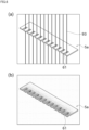
- FIG. 6(a) shows a state of the yarn path region and the first yarn guide 5a when the yarn path is normal.
- the first yarn guide 5a is a comb-like member.
- a plurality of guide grooves 61 for individually guiding the plurality of yarns 93 are formed in the first yarn guide 5a.
- one correct yarn 93 enters one guide groove 61 and is guided, as shown in FIG. 6(a) .
- FIG. 6(b) shows a thermal image generated in this state. As shown in FIG.
- the temperature at the contact points between the yarns 93 and the first yarn guide 5a and the vicinities thereof is higher than the ambient temperature. Furthermore, since the yarns 93 are in all of the guide grooves 61, the temperature of all of the guide grooves 61 is higher than that of the surrounding area.
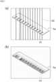
- FIG. 7(a) shows a state of the yarn path region and the first yarn guide 5a when the yarn path is abnormal.
- FIG. 7(a) shows a state where two yarns 93 are inserted into one guide groove 61 and guided, and no yarn 93 is inserted into the other guide groove 61. In other words, a yarn 93 is erroneously guided to an adjacent guide groove 61, and therefore the yarn path is abnormal.
- the thermal image generated in this state is shown in FIG. 7(b) .
- the temperature around the guide groove 61 with the two yarns 93 is higher than the temperature of the other guide grooves 61.
- the temperature around the guide groove 61 in which no yarn 93 is inserted is lower than the temperature of the other guide grooves 61.
- the abnormality in the yarn path clearly appears in a thermal image. Since the yarns 93 are generally thin, it is difficult to accurately specify the yarns 93 using a visible image. However, since the frictional heat generated between the yarns 93 and the guide grooves 61 spreads to the surrounding area, a thermal image can be used to accurately detect an abnormality in the yarn path (specifically, an abnormality regarding whether or not the yarns 93 are in the guide grooves 61, or an abnormality regarding whether or not the yarns 93 have deviated from the normal yarn path during production).
- FIG. 4 conceptually shows processing for the training unit 50b to construct a determination model using machine learning.
- a training thermal image and its correct answer data are used as training data for constructing a determination model.
- the training thermal image is a thermal image generated by capturing an image of the yarn path region including the first yarn guide 5a, and is a thermal image used as training data.
- the image capture device 6 is used to generate a training thermal image.
- a device other than the image capture device 6 may also be used to generate the training thermal image.
- the training data is data in which a training thermal image and correct answer data (label) indicating whether the yarn path shown in the training thermal image is normal or abnormal are associated with each other.
- training data only thermal images with normal yarn paths, only thermal images with abnormal yarn paths, or both may be used.
- the training data includes a plurality of training thermal images. For example, it is easy to capture a thermal image of a normal yarn path (that is, it is easy to prepare learning data). Capturing a thermal image of an abnormal yarn path is time-consuming because it is necessary to intentionally create a state where the yarn path is abnormal, but by learning this, it is possible to accurately determine whether or not the same type of abnormality has occurred.
- the machine learning of this embodiment is supervised learning.
- the specific method for performing machine learning is optional, deep learning is used in this embodiment.
- the training unit 50b can extract features for determining an abnormality in a yarn path from a thermal image by extracting or estimating a training thermal image and the features in the thermal image that indicate whether the yarn path is normal or abnormal. For example, when learning a plurality of training thermal images in which the yarn path is normal, a feature in the thermal images that is held in common among the plurality of training thermal images is learned.
- This feature is, for example, a feature such as the temperature of all of the guide grooves 61 being uniform and/or the maximum temperature of the first yarn guide 5a being high due to the fact that the yarn 93 is in each guide groove 61 of the first yarn guide 5a. Also, when learning a plurality of training thermal images in which the yarn path is abnormal, a feature in the thermal images that is held in common among the plurality of learning thermal images is learned. This feature is, for example, a feature such as the temperature being low and/or the maximum temperature of the first yarn guide 5a being low because the yarn 93 is not in a guide groove 61 of the first yarn guide 5a.
- the training unit 50b constructs a determination model. The determination model constructed by the training unit 50b is stored in the storage unit 50d.
- the determination model described above is an example, and the determination model may be constructed using another method. That is, instead of deep learning, machine learning may be performed by designating a feature amount relating to an abnormality in the yarn path. Also, as described above, machine learning may be performed by directly using the thermal image generated by capturing an image of the yarn path region, and machine learning may be performed after performing some kind of pre-processing on the thermal image generated by capturing an image of the yarn path region. As the pre-processing, for example, image adjustment performed so that the yarn 93 appears clearly in the thermal image, deletion of objects other than the yarn 93 and the first yarn guide 5a, or the like are conceivable.
- pre-processing for example, image adjustment performed so that the yarn 93 appears clearly in the thermal image, deletion of objects other than the yarn 93 and the first yarn guide 5a, or the like are conceivable.
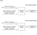
- the determination unit 50c performs the following processing using the determination model. That is, the determination model determines whether or not there is an abnormality in the yarn path based on the thermal image generated by the image capture device 6.
- the thermal image captured by the image capture device 6 at the stage of determining whether or not there is an abnormality in the yarn path will be referred to as a "determination thermal image”.
- the determination model is constructed by learning features in images that indicate whether the yarn path is normal or abnormal. For this reason, the determination model determines whether the yarn path is normal or abnormal based on whether or not the thermal image for determination has these features, or the like.
- an abnormality other than an abnormality in the yarn path can be determined based on a thermal image.
- an abnormality in the yarn tension of the yarn 93 can be detected using the thermal image.
- machine learning may be performed on training data in which a thermal image captured in a normal state where the yarn tension is within a normal range and correct answer data indicating that the yarn tension is normal are associated with each other.
- machine learning may be performed on training data in which a thermal image captured in an abnormal state in which the yarn tension is out of the normal range and correct answer data indicating that the yarn tension is abnormal are associated with each other.
- an abnormality in the amount of oil applied to the yarns 93 can be detected using a thermal image.
- machine learning may be performed on training data in which a thermal image captured in a normal state in which the amount of oil applied is within a normal range and correct answer data indicating that the amount of oil applied is normal are associated with each other.
- machine learning may be performed on training data in which a thermal image captured in an abnormal state in which the amount of oil applied is out of the normal range and correct answer data indicating that the amount of oil applied is abnormal are associated with each other.
- an abnormality in the wear of the first yarn guide 5a can be detected using a thermal image.
- machine learning may be performed on training data in which a thermal image captured in a normal state where the first yarn guide 5a is not worn and correct answer data indicating that the first yarn guide 5a is not worn are associated with each other.
- machine learning may be performed on training data in which a thermal image captured in an abnormal state in which the first yarn guide 5a is worn and correct answer data indicating that the first yarn guide 5a is worn are associated with each other.
- the determination model is created to be able to determine one of the above-mentioned abnormalities.
- the determination model may also be created so as to be able to determine a plurality of abnormalities among the above-mentioned abnormalities.
- the determination model may determine only whether or not at least one of the plurality of abnormalities to be determined has occurred (that is, it does not determine which abnormality has occurred).
- the determination model may determine also which abnormality has occurred among the abnormalities to be determined (in this case, it is necessary to learn thermal images according to individual abnormal states).
- the control device 50 determines whether or not the timing for abnormality determination of the yarns 93 has arrived (S101).
- the timing for abnormality determination of the yarns 93 is set, for example, at every predetermined amount of time while the yarns 93 are being wound. Note that this is an example, and different settings may be made as shown below.
- the timing for abnormality determination of the yarns 93 may be set only at the start of winding the yarn 93. Alternatively, the timing may be set such that the timing for abnormality determination of the yarns 93 is reached when there is an instruction from an operator.
- control unit 50a of the control device 50 determines that the timing for abnormality determination of the yarns 93 has arrived, the control unit 50a instructs the image capture device 6 to capture an image of the yarn path region (S102).
- the determination unit 50c determines whether or not there is an abnormality regarding the yarns 93, as described above, based on the determination model selected by the control device 50 and the determination thermal image that was captured by the image capture device 6 and input to the input unit 50e (S104).
- the control device 50 performs the processing of step S101 again. If the determination unit 50c determines that there is an abnormality regarding the yarns 93 (S105), the control unit 50a of the control device 50 controls the notification unit 65 to notify the operator of the abnormality (S106).
- control device 50 determines whether or not the yarns 93 are abnormal. In particular, by performing detection using a determination model constructed through machine learning, the determination accuracy can be increased.
- the image capture device 6 captures an image of the first yarn guide 5a to generate a determination thermal image.
- the image capture device 6 may capture an image of the oil supply guide 3, the second yarn guide 5b, the third yarn guides 5c, or the traverse guide 23 to generate a determination thermal image.
- the number of yarn guides to be determined may be one or more.
- first yarn guide 5a the first yarn guide 5a, the second yarn guide 5b, and the third yarn guide 5c
- first yarn guide 5a, the second yarn guide 5b, or the third yarn guide 5c is referred to as a "yarn guide 5".
- the determination unit 50c determines whether or not there is an abnormality by using a determination thermal image of the yarn path region.
- the determination unit 50c may also use a determination visible image of the yarn path region to determine whether or not there is an abnormality.
- a visible light camera is prepared and arranged so that its lens faces the yarn path region (specifically, the region including the first yarn guide 5a).
- the visible light camera has an angle of view close to that of the image capture device 6. The visible light camera captures an image of the yarn path region, generates a determination visible image, and outputs the generated image to the control unit 50a.
- the temperature at the contact points between the yarns 93 and the guide grooves 61 is the highest. Also, when the yarn path is normal, the yarns 93 pass through predetermined regions of the guide grooves 61.
- the predetermined regions can be specified from design information. As described above, by using the position of the first yarn guide 5a (in particular, the positions of the guide grooves 61) and the information on the predetermined regions obtained from the determination visible image, it is possible to specify the positions through which the yarns 93 pass when the yarn path is normal in the determination visible image. By applying this information to the determination thermal image, it is possible to identify regions where a high temperature is likely to occur when the yarn path is normal.
- the region with the highest temperature in the determination thermal image when the yarn path is normal (the regions where the yarns 93 and the guide grooves 61 are in contact in the determination thermal image) and the actual temperature distribution in the determination thermal image, it is possible to more accurately determine whether or not the yarn path is normal.
- FIG. 9 is a diagram showing an example of a hardware configuration of the control device 50.
- the control device 50 includes the above-described storage unit 50d (see FIG. 3 ), a processor 81, a communication interface 84, a display interface 85, and an input interface 87. These components are connected to the bus BS. Examples of the storage unit 50d include a ROM (Read Only Memory) 82, a RAM 83, and an auxiliary storage device 90.
- ROM Read Only Memory
- the processor 81 is constituted, for example, by at least one integrated circuit.
- An integrated circuit can be constituted by, for example, at least one CPU, at least one GPU (Graphics Processing Unit), at least one ASIC (Application Specific Integrated Circuit), at least one FPGA (Field Programmable Gate Array), or a combination thereof.
- the processor 81 controls the operation of the control device 50 by executing various programs.
- the processor 81 reads out a program to be executed from the auxiliary storage device 90 or the ROM 82 to the RAM 83 based on receiving execution instructions for various programs.
- the RAM 83 functions as working memory and temporarily stores various types of data necessary for program execution.
- a LAN Local Area Network
- an antenna and the like are connected to the communication interface 84.
- the control device 50 exchanges data with an external device via the communication interface 84.
- the external device includes, for example, a server.
- a display device 86 is connected to the display interface 85.
- the display interface 85 sends an image signal for displaying an image to the display device 86 according to instructions from the processor 81 and the like.
- the display device 86 is, for example, a liquid crystal display, an organic EL (Electro Luminescence) display, or another display. Note that the display device 86 may also be formed integrally with the control device 50, or may be formed separately from the control device 50.
- the input device 88 is connected to the input interface 87.
- the input device 88 is, for example, a mouse, keyboard, touch panel, or other device capable of receiving a user operation. Note that the input device 88 may be formed integrally with the control device 50 or may be formed separately from the control device 50.
- the auxiliary storage device 90 is, for example, a storage medium such as a hard disk, flash memory, and SSD.
- the auxiliary storage device 90 stores, for example, a training dataset 122, a determination model 124, a training program 126, and an abnormality determination program 128. These storage locations are not limited to the auxiliary storage device 90, and may also be stored in the storage region of the processor 81 (e.g., cache memory, etc.), the ROM 82, the RAM 83, an external device (e.g., a server), or the like.
- the training program 126 is a program for generating the determination model 124 using the training dataset 122.
- the training program 126 may be provided not as a standalone program but as a part of any program. In this case, the training processing performed by the training program 126 is realized in cooperation with any program. Even a program that does not include such a part of the module does not deviate from the spirit of the training program 126 according to this embodiment. Furthermore, some or all of the functions provided by the training program 126 may also be realized by dedicated hardware.
- the control device 50 may also be included in a form such as a so-called cloud service in which at least one server executes a part of the processing of the training program 126.
- the abnormality determination program 128 is a program for determining whether or not an abnormality has occurred regarding the yarns passing through the yarn guide 5, using the trained determination model 124.
- the abnormality determination program 128 may be provided not as a standalone program but as a part of any program. In this case, the determination processing performed by the abnormality determination program 128 is realized in cooperation with any program. Even if the program does not include such a part of the module, it does not deviate from the spirit of the abnormality determination program 128 according to this embodiment. Furthermore, some or all of the functions provided by the abnormality determination program 128 may also be realized by dedicated hardware. Furthermore, the control device 50 may also be configured in a mode such as a so-called cloud service in which at least one server executes a part of the processing of the abnormality determination program 128.
- FIG. 10 is a diagram showing an example of the training dataset 122.
- the training dataset 122 includes a plurality of pieces of the training data 123.
- the number of pieces of the training data 123 included in the training dataset 122 is optional. As an example, the number of pieces of the training data 123 is from several tens to hundreds of thousands.
- Each piece of the training data 123 associates, as a label (correct answer value), the type of abnormality regarding the yarns passing through the yarn guide, with respect to a thermal image showing the distribution of surface temperature of the yarn guide 5 described above.
- the training data 123 may be acquired from one spinning take-up machine 1 or from another spinning take-up machine different from the spinning take-up machine 1.
- the number of types of labels defined in the training dataset 122 may be one or more.
- abnormalities "A” to “D” are shown as labels indicating the types of abnormalities.
- the abnormality "A” indicates a yarn path abnormality indicating that a yarn 93 is out of the normal yarn path region on the yarn guide 5.
- the abnormality "B” indicates a tension abnormality indicating that the tension of a yarn 93 passing through the yarn guide 5 is out of the normal range.
- the abnormality “C” indicates an oil application amount abnormality indicating that the amount of oil applied to a yarn 93 passing through the yarn guide 5 is out of the normal range.
- the abnormality "D” indicates a wear abnormality indicating that the amount of wear of the yarn guide 5 is out of the normal range. Note that a label indicating normality may also be associated with the thermal image.
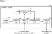
- FIG. 11 is a diagram showing an example of the functional configuration of the control device 50.
- the control device 50 includes a training unit 50b, a determination unit 50c, an input unit 50e, and an output unit 50f as functional configurations.
- these functional configurations will be described in the order of the training unit 50b, the input unit 50e, the determination unit 50c, and the output unit 50f.
- FIG. 12 is a diagram conceptually showing the training processing performed by the training unit 50b.
- the training unit 50b executes training processing using the above-described training dataset 122 (see FIG. 10 ), and generates a determination model 124 for determining whether or not an abnormality has occurred in the yarns 93 passing through the yarn guide 5.
- the machine learning algorithm employed in the training processing is not particularly limited, and for example, deep learning, a convolutional neural network (CNN), a full-layer convolutional neural network (FCN), a support vector machine, or the like may be employed.
- CNN convolutional neural network
- FCN full-layer convolutional neural network
- support vector machine or the like
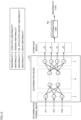
- the determination model 124 is constituted by an input layer X, an intermediate layer H, and an output layer Y
- the input layer X is configured to receive input of a thermal image, which is the training data 123.
- the input layer X is composed of, for example, N units x 1 to x N (N is a natural number).
- the number of units constituting the input layer X is the same as the number of dimensions of input information.
- the input layer X is composed of N units.
- feature amounts extracted from a thermal image may be input to the input layer X.
- the input layer X is configured such that the number of units thereof is the same as the number of dimensions of the feature amount.
- Each unit included in the input layer X outputs input data to each unit in the first layer of the intermediate layer H.
- the intermediate layer H is composed of one layer or multiple layers.
- the intermediate layer H is composed of L layers (L is a natural number).
- L is a natural number
- Each layer of the intermediate layer H includes multiple units.
- the number of units in each layer of the intermediate layer H may be the same or different.
- the first layer of the intermediate layer H is composed of Q units hai to h AQ (Q is a natural number).
- the final layer of the intermediate layer H is composed of R units h L1 to h LR (R is a natural number).
- Each unit constituting each layer of the intermediate layer H is connected to each unit of the previous layer and each unit of the next layer.
- Each unit of each layer receives an output value from each unit of the previous layer, multiplies each output value by a weight, integrates the multiplication results, adds (or subtracts) a predetermined bias to the integration result, inputs the addition result (or subtraction result) to a predetermined function (e.g., a sigmoid function), and outputs the output value of the function to each unit of the next layer.
- a predetermined function e.g., a sigmoid function
- the output layer Y outputs the estimation result according to the input thermal image.
- the output layer Y is composed of units y 1 to y 4 , for example.
- the units y 1 to y 4 are also referred to as units y.
- Each of the units y is connected to the units h L1 to h LR of the final layer of the intermediate layer H.
- Each unit y receives the output value from each unit of the final layer of the intermediate layer H, multiplies each output value by a weight, integrates the multiplication results, adds (or subtracts) a predetermined bias to the integration result, inputs the addition result (or subtraction result) to a predetermined function (e.g., a sigmoid function), and outputs the output result of the function as an output value.
- a predetermined function e.g., a sigmoid function
- the number of units constituting the output layer Y is determined according to the number of abnormality types defined in the training data 123. As an example, when detecting the abnormalities "A" to "D", the number of units constituting the output layer Y is four, namely the units y 1 to y 4 .
- the unit y 1 is configured to output a score "sa” indicating the likelihood that an abnormality "A” has occurred.
- the unit y 2 is configured to output a score "sb” indicating the likelihood that an abnormality "B” has occurred.
- the unit y 3 is configured to output a score "sc” indicating the likelihood that an abnormality "C” has occurred.
- the unit y 4 is configured to output a score "sd” indicating the likelihood that an abnormality "D” has occurred.
- one determination model 124 is configured to output a plurality of scores, but one determination model may also be configured to output one score.
- a first determination model may be configured to output the score "sa” relating to the abnormality "A”
- a second determination model may be configured to output the score "sb” relating to the abnormality "B”
- a third determination model may be configured to output the score "sc” relating to the abnormality "C”
- a fourth determination model may be configured to output the score "sd” relating to the abnormality "D”.
- the training unit 50b inputs the thermal image specified in the first piece of training data 123 to the determination model 124. Next, the training unit 50b compares the estimation results "sa” to “sd” output from the determination model 124 and the correct answer scores "sa"' to “sd'” according to the abnormality type associated with the first piece of training data 123.
- the training unit 50b calculates an error "Z” between the output results “sa” to “sd” of the determination model 124 and the correct scores "sa'" to “sd”'.
- the error "Z” is calculated based on the following equation (1), for example.
- Z sa ⁇ sa ′ 2 + sb ⁇ sb ′ 2 + sc ⁇ sc ′ 2 + sd ⁇ sd ′ 2 / 4
- the training unit 50b updates various parameters (e.g., weights and biases) included in the determination model 124 such that the error "Z" becomes smaller.
- the updating of the parameters is realized, for example, through error backpropagation.
- the training unit 50b inputs the thermal image included in the training data 123 to the determination model 124, and updates the internal parameters of the determination model 124 such that the estimation result output from the determination model 124 approaches the type of abnormality serving as the label associated with the thermal image.
- the training unit 50b repeatedly performs processing for updating the internal parameters of the determination model 124 for each piece of training data 123 included in the training dataset 122.
- the determination model 124 outputs more accurate estimation results as learning progresses.
- the training unit 50b does not need to use all of the training data 123 included in the training dataset 122 for the training processing, but may use some of the training data 123 included in the training dataset 122 to generate the determination model 124. The remaining training data 123 is used, for example, to evaluate the determination model 124.
- the input unit 50e is a communication module for realizing communication with the image capture device 6 described above.
- the control device 50 and the image capture device 6 may be communicatively connected by wire or wirelessly.
- the input unit 50e acquires a determination thermal image from the image capture device 6 by outputting an image capture instruction to the image capture device 6, and inputs the determination thermal image to the determination model 124. At this time, the input unit 50e may input each pixel of the determination thermal image to the determination model 124 as-is, or may input the feature amount extracted from the determination thermal image to the determination model 124. As a result, the determination model 124 outputs a score indicating the likelihood that an abnormality has occurred in the yarns 93 passing through the yarn guide 5 as the type of abnormality.
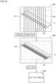
- FIG. 13 is a diagram conceptually showing abnormality determination processing performed by the determination unit 50c.
- the determination model 124 outputs, as estimation results, the score "sa” indicating the likelihood that the abnormality “A” has occurred, the score “sb” indicating the likelihood that the abnormality “B” has occurred, the score “sc” indicating the likelihood that the abnormality “C” has occurred, and the score “sd” indicating the likelihood that the abnormality "D” has occurred.
- the determination unit 50c determines the type of abnormality that has occurred based on the scores "sa”, “sb”, “sc", and "sd”.
- the determination unit 50c determines that the abnormality "A" has occurred.
- the first threshold may be set in advance or may be set as appropriate by the user.
- the determination unit 50c determines that the abnormality "B" has occurred.
- the second threshold may be set in advance or may be set as appropriate by the user. Also, the second threshold may be the same as the first threshold or may be different from the first threshold.
- the determination unit 50c determines that the abnormality "C" has occurred when the score "sc" exceeds a third threshold.
- the third threshold may be set in advance or may be set as appropriate by the user. Also, the third threshold may be the same as the first and second thresholds, or may be different from the first and second thresholds.
- the determination unit 50c determines that the abnormality "D" has occurred when the score "sd” exceeds the fourth threshold.
- the fourth threshold may be set in advance or may be set as appropriate by the user. Also, the fourth threshold may be the same as the first to third thresholds, or may be different from the first to third thresholds.
- the determination unit 50c determines that the score "sa" is less than or equal to the first threshold, the score “sb” is less than or equal to the second threshold, the score “sc” is less than or equal to the third threshold, and the score “sd” is less than or equal to the fourth threshold, the determination unit 50c determines that no abnormality has occurred. That is, in this case, the determination unit 50c determines that the yarn 93 is passing through the yarn guide 5 normally.
- the output unit 50f outputs a control command corresponding to the determination result obtained by the determination unit 50c to a predetermined output destination.
- the output unit 50f outputs a warning display command to the above-described display device 86 (see FIG. 9 ).
- the display device 86 displays a warning indicating that an abnormality has occurred in the yarn guide 5.
- the warning displayed on the display device 86 includes, for example, the type of abnormality that has occurred and a determination thermal image indicating the abnormality.
- the warning display command may also be transmitted to a communication terminal registered in advance. This allows the person in charge or manager to recognize that an abnormality has occurred in the yarn guide 5 in the spinning take-up machine 1.
- the output unit 50f outputs a warning notification command to the above-mentioned notification unit 65 (see FIG. 3 ).
- the notification unit 65 serving as a notification lamp emits light according to the type of abnormality that has occurred.
- the notification unit 65 serving as a notification buzzer emits a sound according to the type of abnormality that has occurred.
- the output unit 50f lights the notification lamp in green. Also, when the determination result indicates a yarn path abnormality, the output unit 50f causes the notification lamp to blink in red. Furthermore, if the determination result indicates an abnormality in the amount of oil applied, the output unit 50f causes the notification lamp to blink in red. Furthermore, if the determination result indicates a tension abnormality, the output unit 50f causes the notification lamp to blink in yellow. If the determination result indicates abnormal wear of the yarn guide 5, the output unit 50f lights the notification lamp in yellow.
- the output unit 50f may cause the notification buzzer to perform notification of an abnormal state.
- the output unit 50f causes the notification buzzer to output a sound corresponding to the type of abnormality.
- the output unit 50f may output a notification indicating that an abnormality has occurred if the determination result indicates an abnormality in the yarn path, an abnormality in the amount of oil applied, an abnormality in tension, or an abnormality in wear.
- the notification may be displayed on the display device 86 described above, or may be transmitted to an external device.
- the content included in the notification includes, for example, the identifier of the spinning take-up machine in which the abnormality has occurred (e.g., the machine ID) and the type of the abnormality in which the abnormality has occurred.
- the output unit 50f outputs a log storage command to the above-mentioned storage unit 50d (see FIG. 3 ).
- the storage unit 50d stores a log corresponding to the type of abnormality that has occurred.
- the log includes the time when the abnormality occurred, the type of abnormality that has occurred, and a determination thermal image showing the abnormality.
- the training unit 50b and the determination unit 50c are installed in the same spinning take-up machine 1.
- the training unit 50b and the determination unit 50c do not necessarily need to be installed in the same spinning take-up machine 1.
- the training unit 50b may be implemented in a different device.
- FIG. 14 is a diagram showing an example of the device configuration of an abnormality determination system 500 in this modified example.
- the abnormality determination system 500 includes one or more spinning take-up machines 1 and one or more information processing devices 200.
- the abnormality determination system 500 includes three spinning take-up machines 1A to 1C and one information processing device 200.
- the spinning take-up machines 1A to 1C and the information processing device 200 are connected to the same network NW and are configured to be able to communicate with each other.
- the spinning take-up machine 1 and the information processing device 200 may be communicatively connected by wire or wirelessly.
- the information processing device 200 is a desktop computer, a laptop computer, a tablet terminal, or other information processing terminal.
- the training unit 50b is installed in the information processing device 200. Also, the determination unit 50c is installed in the spinning take-up machine 1C.
- the information processing device 200 collects the above-mentioned training data 123 (see FIG. 10 ) from the spinning take-up machines 1 (e.g., the spinning take-up machines 1A, 1B) connected to the network NW.
- the training unit 50b of the information processing device 200 executes training processing using the training data 123 collected from all of the spinning take-up machines 1, and generates the above-described determination model 124. Since the functions of the training unit 50b are as described above, the description thereof will not be repeated.
- the information processing device 200 transmits the generated determination model 124 to the spinning take-up machine 1 (for example, the spinning take-up machine 1C).
- the determination unit 50c uses the determination model 124 to determine whether or not an abnormality has occurred in the yarn guide 5 in the spinning take-up machine 1C. Since the function of the determination unit 50c is as described above, the description thereof will not be repeated.
- the heat (temperature) generated by friction between the yarns 93 and the first yarn guide 5a varies depending on the operating condition of the spinning take-up machine 1. For example, as the traveling speed of the yarns 93 increases, the temperature of the first yarn guide 5a tends to increase. Also, since the coefficient of friction changes depending on the material of the yarns 93, the temperature of the first yarn guide 5a changes.
- the above-described determination model 124 is created for each operating condition of the spinning take-up machine 1.
- FIG. 15 is a diagram showing an example of a training dataset 122A according to this modified example.
- the training dataset 122A includes a plurality of pieces of training data 123A.
- the number of pieces of training data 123A included in the training dataset 122A is optional. As an example, the number of pieces of training data 123A is from several tens to hundreds of thousands.
- the abnormality type relating to the yarns 93 was associated with the thermal image showing the distribution of the surface temperature of the yarn guide 5 as a label (correct answer value).
- the operating condition of the spinning take-up machine 1 or other spinning take-up machine is further associated with the training thermal image.
- the operating condition includes, for example, the travel speed of the yarn 93, the material of the yarns 93, and the like.
- the training unit 50b described above classifies the training data 123Aincluded in the training dataset 122A for each group of operating conditions that are similar. Any method can be adopted as the classification method. As an example, the training data 123A is classified by clustering. The number of classes (number of classifications) may be set in advance or may be automatically determined.
- clustering methods include hierarchical methods and non-hierarchical methods.
- hierarchical clustering methods include a method of sequentially linking two points that are close to each other in a space indicated by an index including at least one of the travel speed of the yarns 93 and the material of the yarns 93, and performing the linking until the distance exceeds a predetermined value.
- non-hierarchical clustering methods include the k-means method.
- the training unit 50b executes the above-described training processing for each set of pieces of the training data 123A belonging to the same class.
- the training processing is as described above with reference to FIG. 12 , and therefore the description thereof will not be repeated.
- the determination models 124 are generated for corresponding operating condition ranges of the spinning take-up machine 1.
- Each of the determination models 124 is stored with an operating condition range associated therewith.
- FIG. 16 is a diagram showing a flowchart relating to determination processing according to this modified example.
- step S103 has been added. Other points are as described in FIG. 8 , and therefore the description thereof will not be repeated.
- step S103 the determination unit 50c described above acquires the current operating condition of the spinning take-up machine 1.
- the operating condition includes, for example, the travel speed of the yarns 93, the material of the yarns 93, and the like.
- the operating condition is input to the above-mentioned input unit 50e, for example.
- the determination unit 50c acquires the determination model 124 corresponding to the current operating condition of the spinning take-up machine 1 from among the determination models 124 generated by the training unit 50b. More specifically, the determination unit 50c specifies the operating condition range to which the current operating condition belongs from among the operating condition ranges associated with each of the determination models 124, and selects the determination model 124 corresponding to the operating condition range. Thereafter, the determination unit 50c uses the selected determination model 124 to execute the above-described abnormality determination processing.
- the abnormality determination processing performed by the determination unit 50c is as described above with reference to FIG. 13 , and therefore the description thereof will not be repeated.
- the determination models 124 are generated for each group of operating conditions that are similar has been described above, there is no limitation to this way of using the operating condition of the spinning take-up machine 1.
- the above-described training unit 50b executes the training processing using not only the thermal image included in the training data 123A but also the operating condition.
- the determination model 124 is configured to accept not only input of thermal images but also input of the operating condition.
- the input unit 50e described above inputs not only the determination thermal image but also the current operating condition of the spinning take-up machine 1 to the determination model 124.
- the determination model 124 more accurately outputs a score indicating the likelihood that an abnormality has occurred in the yarn 93 passing through the yarn guide 5.
- the determination models 124 are generated for each group of operating conditions that are similar, but the determination models 124 may also be generated for each group of pieces of information other than the operating conditions. As an example, the determination models 124 may also be generated for corresponding image capture conditions of the yarn guide 5 by the image capture device 6.
- the image capture conditions include, for example, the relative positional relationship of the image capture device 6 with respect to the yarn guide 5.
- FIG. 17 is a diagram showing an example of the training dataset 122B according to this modified example.
- the training dataset 122B includes a plurality of pieces of training data 123B.
- the number of pieces of training data 123B included in the training dataset 122B is optional. As an example, the number of pieces of training data 123B is from several tens to hundreds of thousands.
- the abnormality type relating to the yarns 93 was associated with the thermal image showing the distribution of the surface temperature of the yarn guide 5 as a label (correct answer value).
- information indicating the positional relationship between the yarn guide 5 and the image capture device 6 is further associated with the training thermal image.
- the positional relationship is defined, for example, by at least one of the relative coordinate values of the image capture device 6 with respect to the yarn guide 5 and the angle of view of the image capture device 6 with respect to the yarn guide 5.
- the above-mentioned positional relationship included in the training data 123 may be the positional relationship between the yarn guide 5 and the image capture device 6 provided in the spinning take-up machine 1, or the positional relationship between the yarn guide 5 and the image capture device 6 provided in a type of device other than the spinning take-up machine 1.
- the training unit 50b described above classifies the training data 123B included in the training dataset 122B for each group of positional relationships that are similar. Any method can be adopted as the classification method. As an example, the training data 123B is classified by clustering. The number of classes (number of classifications) may be set in advance or may be automatically determined.
- clustering methods include hierarchical methods and non-hierarchical methods.
- hierarchical clustering methods include a method of sequentially linking two points that are close to each other in a space indicated by an index including at least one of the relative coordinate values of the image capture device 6 with respect to the yarn guide 5 and the angle of view of the image capture device 6 with respect to the yarn guide 5, and performing the linking until the distance exceeds a predetermined value.
- non-hierarchical clustering methods include the k-means method.
- the training unit 50b executes the above-described training processing for each set of pieces of the training data 123B belonging to the same class.
- the training processing is as described above with reference to FIG. 12 , and therefore the description thereof will not be repeated.
- the determination models 124 are generated for corresponding positional relationships that are similar.
- Each of the determination models 124 is stored with a positional relationship associated therewith.
- FIG. 18 is a diagram showing a flowchart relating to determination processing according to this modified example.
- step S103A has been added.
- Other points are as described in FIG. 8 , and therefore the description thereof will not be repeated.
- step S103A the determination unit 50c described above obtains the positional relationship between the yarn guide 5 and the image capture device 6.
- the positional relationship may be set in advance or may be input by the user.
- the positional relationship is input to, for example, the above-mentioned input unit 50e.
- the positional relationship between the yarn guide 5 and the image capture device 6 will also be referred to as the "input positional relationship”.
- the determination unit 50c obtains a determination model 124 corresponding to the input positional relationship from among the determination models 124 generated by the training unit 50b. More specifically, the determination unit 50c specifies the positional relationship to which the input positional relationship belongs from among the positional relationships associated with each of the determination models 124, and selects the determination model 124 corresponding to the positional relationship. Thereafter, the determination unit 50c uses the selected determination model 124 to execute the above-described abnormality determination processing.
- the abnormality determination processing performed by the determination unit 50c is as described above with reference to FIG. 13 , and therefore the description thereof will not be repeated.
- the determination model 124 is generated for each group of positional relationships that are similar has been described above, there is no limitation to this way of using the positional relationship.
- the above-mentioned training unit 50b executes the training processing using not only the thermal image included in the training data 123B but also the above-mentioned positional relationship.
- the determination model 124 is configured to accept not only input of a thermal image but also input of the above-mentioned positional relationship.
- the input unit 50e described above inputs not only the determination thermal image but also the positional relationship between the yarn guide 5 and the image capture device 6 to the determination model 124.
- the determination model 124 more accurately outputs a score indicating the likelihood that an abnormality has occurred in the yarn 93 passing through the yarn guide 5.
- FIG. 19 is a diagram schematically showing cutout processing according to this modified example.
- the control device 50 can improve learning accuracy and determination accuracy by cutting out a predetermined region within the thermal image and using image information of the cutout region for training processing and determination processing.
- the position of the image capture device 6 with respect to the yarn guide 5 may change depending on the model of the spinning take-up machine 1.
- the control device 50 according to this modified example first specifies the region of the yarn guide 5 in the thermal image.
- a visible light camera (not shown) is provided in addition to the image capture device 6 serving as a thermal camera.
- the visible light camera is installed inside the spinning take-up machine 1 so that its image capture field of view includes the yarn guide 5.
- the visible light camera is provided adjacent to the image capture device 6.
- the angle formed by the optical axis of the visible light camera and the optical axis of the image capture device 6 is less than or equal to a predetermined angle (for example, less than or equal to 10°).
- the predetermined angle is 0°.
- the optical axis of the visible light camera is parallel to the optical axis of the image capture device 6.
- FIG. 19 shows a visible image IM1 obtained from the visible light camera and a thermal image IM2 obtained from the image capture device 6.
- the control device 50 specifies an image region R1 in which the yarn guide 5 appears from the visible image IM1 using a predetermined object detection algorithm. Any known algorithm may be employed as the object detection algorithm.
- the control device 50 specifies an image region R2 in which the yarn guide 5 appears in the thermal image IM2 based on the position of the image region R1 in the visible image IM1.
- the position of the image region R2 in the thermal image IM2 can be specified based on the position of the image region R1 in the visible image IM1.
- the control device 50 makes the position of the image region R2 in the thermal image IM2 the same as the position of the image region R1 in the visible image IM1.
- control device 50 projectively transforms the image region R1 in the visible image IM1 based on a predetermined projection matrix, and specifies the region resulting from the projective transformation as the image region R2 in the thermal image IM2.
- the projection matrix is determined in advance based on the positional relationship between the visible light camera and the image capture device 6.
- control device 50 cuts out the image region R2 within the thermal image IM2 and generates a cutout image IM3.
- the cutout image IM3 can be used for training processing performed by the training unit 50b described above. Also, the cutout image IM3 can be used in the determination processing performed by the determination unit 50c described above.
- FIG. 20 is a side view of the false-twisting machine (synthetic fiber manufacturing equipment) 100.
- the false-twisting machine 100 processes synthetic yarns 104. As shown in FIG. 20 , the false-twisting machine 100 includes a yarn feeding portion 101, a processing portion 102, and a winding portion 103.
- the yarn feeding portion 101 includes a mechanism for holding a plurality of packages obtained by winding the synthetic yarns 104.
- the yarn feeding portion 101 supplies a plurality of synthetic yarns 104 to be processed by the processing portion 102 to the processing portion 102.
- the processing portion 102 performs false-twisting on the synthetic yarns 104.
- the processing portion 102 includes, in order from the upstream side in the travel direction of the synthetic yarns 104: a first feed roller 105, a yarn guide 106, a first heating device 107, a cooling device 108, a false-twisting device 109, a second feed roller 110, a yarn combining device 111, a third feed roller 112, a second processing device 113, and a fourth feed roller 114.
- the first feed roller 105 is constituted by opposing rollers, and rotates while sandwiching the plurality of synthetic yarns 104, thereby pulling out the synthetic yarns 104 from the plurality of packages in the yarn feeding portion 101, respectively.
- the yarn guide 106 individually guides each of the plurality of synthetic yarns 104 pulled out by the first feed roller 105.
- the first heating device 107 includes, for example, a heater, and heats the plurality of synthetic yarns 104. Also, inside the first heating device 107, a yarn guide (not shown) is provided.
- the cooling device 108 cools the plurality of synthetic yarns 104 using, for example, airflow. Also, inside the cooling device 108, a yarn guide (not shown) is provided.
- the false-twisting device 109 performs false-twisting on the plurality of synthetic yarns 104.
- the second feed roller 110 draws out the plurality of synthetic yarns 104 that have undergone false-twisting by the false-twisting device 109.
- the yarn combining device 111 combines two synthetic yarns 104 together.
- the third feed roller 112 draws out the plurality of synthetic yarns 104 that have been combined by the yarn combining device 111.
- the second processing device 113 heats the plurality of synthetic yarns 104 again.
- the fourth feed roller 114 pulls out the plurality of synthetic yarns 104 that were heated by the second processing device 113.
- the winding portion 103 winds each of the plurality of synthetic yarns 104 drawn out by the fourth feed roller 114 to manufacture a plurality of packages.
- an image capture device 6 similar to that of the above-described embodiment is arranged.
- the image capture device 6 is arranged so that its lens faces the yarn guide 106, and captures an image of the yarn guide 106 to generate a determination thermal image. Since relatively high yarn tension is applied to the synthetic yarns 104 near the yarn guide 106, high frictional heat is likely to be generated. Accordingly, by performing the same processing as in the above-described embodiment based on the thermal image of the yarn guide 106, abnormalities in the yarn path can be detected.
- the image capture device 6 may also capture an image of a part other than the yarn guide 106 to generate a determination thermal image.
- a determination thermal image may also be generated by capturing an image of a yarn guide inside the first heating device 107, a yarn guide inside the cooling device 108, a traverse guide provided in the winding portion 103, or the like.
- the control device 50 of this embodiment includes the input unit 50e, the determination unit 50c, and the output unit 50f.
- a thermal image including a yarn path region that is a part of the first yarn guide 5a (yarn guide 106; the same applies below) included in the spinning take-up machine 1 (or the false-twisting machine 100; the same applies below) is input to the input unit 50e (input step, input means).
- the determination unit 50c determines whether or not there is an abnormality regarding the yarn 93 based on the thermal image input to the input unit 50e (determination step, determination means).
- the output unit 50f outputs the determination result of the determination unit 50c (output step, output means).
- control device 50 performs an abnormality determination method including an input step, a determination step, and an output step. Also, the storage unit 50d of the control device 50 stores an abnormality determination program for causing the control device 50 to function as input means, determination means, and output means.
- the friction state occurring in the first yarn guide 5a is different depending on whether the yarn 93 is normal or abnormal, and therefore the temperature of the first yarn guide 5a is different depending on whether the yarn 93 is normal or abnormal. Also, even if the yarn 93 is so thin that it is difficult to detect the yarn 93 itself, the frictional heat spreads, and therefore the yarn 93 can be indirectly detected using a thermal image. As described above, abnormalities regarding the yarn 93 can be determined with high accuracy based on the thermal image including the yarn path region that is a part of the first yarn guide 5a.
- the determination unit 50c determines whether or not there is an abnormality in the yarn path based on the thermal image input to the input unit 50e.
- the temperature of the first yarn guide 5a changes, and therefore it is possible to accurately determine whether or not there is an abnormality in the yarn path.
- the determination unit 50c determines whether or not there is an abnormality in the yarn tension based on the thermal image input to the input unit 50e.
- the temperature of the first yarn guide 5a changes, and therefore it is possible to accurately determine whether or not there is an abnormality in the yarn tension.
- the determination unit 50c determines whether or not there is an abnormality in the amount of oil applied to the yarns 93 based on the thermal image input to the input unit 50e.
- the temperature of the first yarn guide 5a changes, and therefore it is possible to accurately determine whether or not there is an abnormality in the amount of oil applied to the yarns 93.
- the control device 50 of this embodiment stores a plurality of determination models corresponding to an operating condition.
- the determination unit 50c determines whether or not there is an abnormality regarding the yarns 93 based on the determination model selected according to the current operating condition and the thermal image input to the input unit 50e.
- the thermal image input to the input unit 50e is captured by the image capture device 6.
- a thermal image including the yarn path region can be acquired and used to determine abnormalities regarding the yarns 93.
- the control device 50 of this embodiment outputs the result of determination of abnormalities regarding the yarns 93 of the spinning take-up machine 1 serving as synthetic fiber manufacturing equipment.
- the control device 50 of the above-mentioned other embodiment outputs the result of determination of abnormality in the synthetic yarns 104 of the false-twisting machine 100 serving as synthetic fiber manufacturing equipment.
- the determination model is constructed by performing machine learning using, as training data, a training thermal image generated by capturing an image of a yarn path region in advance.
- the determination model is a model for determining whether or not the yarns 93 are abnormal.
- the determination unit 50c determines abnormalities regarding the yarns 93 using the determination thermal image and the determination model.
- This processing may also be performed using two models. That is, when creating the determination model, the training unit 50b constructs a first determination model using, as training data, the training thermal image and correct answer data indicating the temperature determination location (specifically, the location where the yarns 93 and the first yarn guide 5a are in contact with each other in a normal state, and the vicinity thereof). Next, the training unit 50b constructs a second determination model using, as training data, the temperature distribution at the temperature determination location and the correct answer data indicating whether or not the yarns 93 or the first yarn guide 5a is abnormal.
- the determination unit 50c determines the range of the temperature determination location based on the determination thermal image and the first determination model. Next, the determination unit 50c determines whether or not the yarns 93 or the first yarn guide 5a is abnormal based on the range of the temperature determination location and the second determination model, and outputs the determination result.
- the flowchart shown in the above-described embodiment is an example, and some processing may be omitted, the contents of some processing may be changed, or new processing may be added.
- the image capture device 6 captures an image of the yarn path region when there is an instruction from the control device 50, but the image capture device 6 may also spontaneously capture an image of the yarn path region at predetermined time intervals and output the determination heat image to the control device 50.
- this embodiment includes the following disclosures.
- an abnormality determination device having the following configuration. That is, the abnormality determination device includes an input unit, a determination unit, and an output unit. A thermal image including a yarn path region that is a part of a yarn guide included in synthetic fiber manufacturing equipment is input to the input unit. The determination unit determines whether or not there is an abnormality regarding the yarn based on the thermal image input to the input unit. The output unit outputs the determination result of the determination unit.
- the temperature of the yarn guide is different depending on whether the yarn is normal or abnormal. Also, even if the yarn is so thin that it is difficult to detect the yarn itself, the frictional heat spreads, and therefore the yarn can be detected indirectly using a thermal image. As described above, it is possible to accurately determine abnormalities regarding the yarn based on a thermal image including the yarn path region that is a part of the yarn guide.
- the determination unit determines whether or not there is an abnormality in the yarn path based on the thermal image input to the input unit.
- the temperature of the yarn guide changes, and therefore it is possible to accurately determine whether there is an abnormality in the yarn path.
- the determination unit determines whether or not there is an abnormality in the yarn tension based on the thermal image input to the input unit.
- the temperature of the yarn guide changes, and therefore it is possible to accurately determine whether or not there is an abnormality in the yarn tension.
- the determination unit determines whether or not there is an abnormality in the amount of oil applied to the yarn based on the thermal image input to the input unit.
- the temperature of the yarn guide changes, and therefore it is possible to accurately determine an abnormality in the amount of oil applied.
- the abnormality determination device described above preferably has the following configuration. That is, the abnormality determination device includes a plurality of the determination models corresponding to operating conditions. The determination unit determines whether or not there is an abnormality regarding the yarn based on the determination model selected according to the current operating condition and the thermal image input to the input unit.
- the thermal image input to the input unit is captured by an image capture device.
- a thermal image including the yarn path region can be acquired and used to determine abnormalities regarding the yarn.
- the abnormality determination device it is preferable to output a result of determination of abnormality regarding the yarn of the spinning take-up machine serving as the synthetic fiber manufacturing equipment.
- the abnormality determination device it is preferable to output a result of determination of abnormality regarding the yarn of a false-twisting machine serving as the synthetic fiber manufacturing equipment.
- the abnormality determination method includes an input step, a determination step, and an output step.
- the input step a thermal image including a yarn path region that is a part of a yarn guide included in synthetic fiber manufacturing equipment is input.
- the determination step it is determined whether or not there is an abnormality regarding the yarn based on the thermal image input in the input step.
- the output step the determination result in the determination step is output.
- an abnormality determination program for causing a computer to function as the following means.
- the means include an input means, a determination means, and an output means.
- the input means receives input of a thermal image including a yarn path region that is a part of a yarn guide provided in synthetic fiber manufacturing equipment.
- the determination means determines whether or not there is an abnormality regarding the yarn based on the thermal image input by the input means.
- the output means outputs the determination result of the determination means.
Landscapes
- Engineering & Computer Science (AREA)
- Textile Engineering (AREA)
- Physics & Mathematics (AREA)
- Theoretical Computer Science (AREA)
- General Physics & Mathematics (AREA)
- Life Sciences & Earth Sciences (AREA)
- Software Systems (AREA)
- General Health & Medical Sciences (AREA)
- Health & Medical Sciences (AREA)
- Chemical & Material Sciences (AREA)
- Evolutionary Computation (AREA)
- Artificial Intelligence (AREA)
- Computing Systems (AREA)
- General Engineering & Computer Science (AREA)
- Data Mining & Analysis (AREA)
- Mathematical Physics (AREA)
- Computational Linguistics (AREA)
- Mechanical Engineering (AREA)
- Computer Vision & Pattern Recognition (AREA)
- Biomedical Technology (AREA)
- Biophysics (AREA)
- Analytical Chemistry (AREA)
- Biochemistry (AREA)
- Immunology (AREA)
- Pathology (AREA)
- Molecular Biology (AREA)
- Materials Engineering (AREA)
- Wood Science & Technology (AREA)
- Multimedia (AREA)
- Medical Informatics (AREA)
- Quality & Reliability (AREA)
- Filamentary Materials, Packages, And Safety Devices Therefor (AREA)
- Yarns And Mechanical Finishing Of Yarns Or Ropes (AREA)
- Investigating Materials By The Use Of Optical Means Adapted For Particular Applications (AREA)
- Investigating Or Analyzing Materials Using Thermal Means (AREA)
- Radiation Pyrometers (AREA)
- Treatment Of Fiber Materials (AREA)
- Spinning Methods And Devices For Manufacturing Artificial Fibers (AREA)
- Image Analysis (AREA)
Abstract
Description
- The present disclosure mainly relates to an abnormality determination device, an abnormality determination method and an abnormality determination program that outputs an abnormality determination result relating to a yarn in synthetic fiber manufacturing equipment.
-
Japanese Patent Application Laid-Open No. H11-279923 -
Japanese Patent Application Laid-Open No. H11-279923 - In
Patent Document 1, the pixel in the video signal to which the yarn corresponds is stored in advance. However, since the width of the yarn is generally narrow and the position of the yarn changes easily, a situation in which the yarn is not displayed at the corresponding pixel may occur frequently. That is, it may not be possible to accurately detect an abnormality regarding the yarn by merely analyzing a visible image including the yarn. - The present disclosure has been made in view of the above circumstances, and a main purpose thereof is to provide an abnormality determination device that can accurately determine an abnormality regarding a yarn.
- In one example of the present disclosure, an abnormality determination device is provided. The above-described abnormality determination device includes: an input unit configured to receive input of a thermal image including a yarn path region, which is a part of a yarn guide included in synthetic fiber manufacturing equipment; a determination unit configured to determine whether or not there is an abnormality regarding a yarn based on the thermal image input to the input unit; and an output unit configured to output a determination result of the determination unit.
- In one example of the present disclosure, the determination unit determines whether or not there is the abnormality based on the thermal image for determination input to the input unit and a determination model generated by performing machine learning on a plurality of pieces of training data. Each of the plurality of pieces of training data associates, as a label, whether or not there is the abnormality regarding the yarn passing through the yarn guide with a thermal image for training in which the yarn guide included in the synthetic fiber manufacturing equipment or other synthetic fiber manufacturing equipment appears.
- In one example of the present disclosure, the abnormality determination device further includes a training unit configured to generate the determination model from the plurality of pieces of training data.
- In one example of the present disclosure, the abnormality includes an abnormality in a yarn path.
- In one example of the present disclosure, the abnormality includes an abnormality in yarn tension.
- In one example of the present disclosure, the abnormality includes an abnormality in an amount of oil applied to the yarn.
- In one example of the present disclosure, the abnormality determination device includes a plurality of the trained determination models for corresponding operating conditions that are similar. The determination unit selects the determination model corresponding to the current operating condition from among the plurality of determination models, and determines whether or not there is the abnormality based on the selected determination model and the thermal image for determination input to the input unit.
- In one example of the present disclosure, the synthetic fiber manufacturing equipment further includes an image capture device configured to be capable of capturing an image of the yarn guide. The thermal image to be input to the input unit is acquired from the image capture device.
- In one example of the present disclosure, the abnormality determination device includes a plurality of the trained determination models for corresponding positional relationships between the yarn guide and the image capture device included in the synthetic fiber manufacturing equipment or the other synthetic fiber manufacturing equipment. The determination unit selects the determination model corresponding to a positional relationship between the yarn guide and the image capture device included in the synthetic fiber manufacturing equipment from among the plurality of determination models, and determines whether or not there is the abnormality based on the selected determination model and the thermal image for determination input to the input unit.
- In one example of the present disclosure, the synthetic fiber manufacturing equipment is a spinning take-up machine.
- In one example of the present disclosure, the synthetic fiber manufacturing equipment is a false-twisting machine.
- In other examples of the present disclosure, an abnormality determination method is provided. The abnormality determination method includes: a step of inputting a thermal image including a yarn path region, which is a part of a yarn guide included in synthetic fiber manufacturing equipment; a step of determining whether or not there is an abnormality regarding a yarn based on the thermal image input in the step of inputting; and a step of outputting a determination result of the step of determining.
- In one example of the present disclosure, in the step of determining, it is determined whether or not there is the abnormality based on the thermal image for determination input in the step of inputting and a determination model generated by performing machine learning of a plurality of pieces of training data. Each of the plurality of pieces of training data associates, as a label, whether or not there is the abnormality regarding the yarn passing through the yarn guide with a thermal image for training in which the yarn guide included in the synthetic fiber manufacturing equipment or other synthetic fiber manufacturing equipment appears.
- In one example of the present disclosure, the abnormality determination method further includes a step of generating the determination model from the plurality of pieces of training data.
- In one example of the present disclosure, the abnormality includes an abnormality in a yarn path.
- In one example of the present disclosure, the abnormality determination method further includes a step of acquiring a plurality of the trained determination models for corresponding operating conditions that are similar. The step of determining includes: a step of selecting the determination model corresponding to the current operating condition from among the plurality of determination models; and a step of determining whether or not there is the abnormality based on the selected determination model and the thermal image for determination input in the step of inputting.
- In one example of the present disclosure, the synthetic fiber manufacturing equipment further includes an image capture device configured to be capable of capturing an image of the yarn guide. The thermal image to be input in the step of inputting is acquired from the image capture device.
- In one example of the present disclosure, the abnormality determination method further includes a step of acquiring a plurality of the trained determination models for corresponding positional relationships between the yarn guide and the image capture device included in the synthetic fiber manufacturing equipment or the other synthetic fiber manufacturing equipment. The step of determining includes: a step of selecting the determination model corresponding to a positional relationship between the yarn guide and the image capture device included in the synthetic fiber manufacturing equipment from among the plurality of determination models, and a step of determining whether or not there is the abnormality based on the selected determination model and the thermal image for determination input in the step of inputting.
- In another example of the present disclosure, an abnormality determination program is provided. The abnormality determination program causes an abnormality determination device to execute: a step of inputting a thermal image including a yarn path region, which is a part of a yarn guide included in synthetic fiber manufacturing equipment; a step of determining whether or not there is an abnormality regarding a yarn based on the thermal image input in the step of inputting; and a step of outputting a determination result of the step of determining.
- In one example of the present disclosure, in the step of determining, it is determined whether or not there is the abnormality based on the thermal image for determination input in the step of inputting and a determination model generated by performing machine learning of a plurality of pieces of training data. Each of the plurality of pieces of training data associates, as a label, whether or not there is the abnormality regarding a yarn passing through the yarn guide with a thermal image for training in which the yarn guide included in the synthetic fiber manufacturing equipment or other synthetic fiber manufacturing equipment appears.
- In one example of the present disclosure, the abnormality determination program further causes the abnormality determination device to execute a step of generating the determination model from the plurality of pieces of training data.
- In one example of the present disclosure, the abnormality includes an abnormality in a yarn path.
- In one example of the present disclosure, the abnormality determination program further causes the abnormality determination device to execute a step of acquiring a plurality of the trained determination models for corresponding operating conditions that are similar. The step of determining includes: a step of selecting the determination model corresponding to the current operating condition from among the plurality of determination models; and a step of determining whether or not there is the abnormality based on the selected determination model and the thermal image for determination input in the step of inputting.
- In one example of the present disclosure, the synthetic fiber manufacturing equipment further includes an image capture device configured to be capable of capturing an image of the yarn guide. The thermal image to be input in the step of inputting is acquired from the image capture device.
- In one example of the present disclosure, the abnormality determination program further causes the abnormality determination device to execute a step of acquiring a plurality of the trained determination models for corresponding positional relationships between the yarn guide and the image capture device included in the synthetic fiber manufacturing equipment or the other synthetic fiber manufacturing equipment. The step of determining includes: a step of selecting the determination model corresponding to a positional relationship between the yarn guide and the image capture device included in the synthetic fiber manufacturing equipment from among the plurality of determination models, and a step of determining whether or not there is the abnormality based on the selected determination model and the thermal image for determination input in the step of inputting.
-
-
FIG. 1 is a diagram showing a side view of a spinning take-up machine according to an embodiment of the present invention. -
FIG. 2 is a diagram showing a front view of a yarn winding machine. -
FIG. 3 is a diagram showing a block diagram of the yarn winding machine. -
FIG. 4 is a diagram showing processing for constructing a determination model through machine learning. -
FIG. 5 is a diagram showing processing for obtaining a determination result using a determination model. -
FIG. 6 is a diagram showing a state and a thermal image of a yarn path region and a yarn guide when yarns and the yarn guide are normal. -
FIG. 7 is a diagram showing a state and a thermal image of the yarn path region and the yarn guide when the yarns or the yarn guide is abnormal. -
FIG. 8 is a diagram showing a flowchart regarding yarn abnormality determination using a determination model. -
FIG. 9 is a diagram showing an example of a hardware configuration of a control device. -
FIG. 10 is a diagram showing an example of a training dataset. -
FIG. 11 is a diagram showing an example of a functional configuration of a control device. -
FIG. 12 is a diagram conceptually showing training processing performed by a training unit. -
FIG. 13 is a diagram conceptually showing abnormality determination processing performed by a determination unit. -
FIG. 14 is a diagram showing an example of a device configuration of an abnormality determination system. -
FIG. 15 is a diagram showing an example of a training dataset. -
FIG. 16 is a diagram showing a flowchart regarding determination processing. -
FIG. 17 is a diagram showing an example of a training dataset. -
FIG. 18 is a diagram showing a flowchart regarding determination processing. -
FIG. 19 is a diagram schematically showing cutout processing. -
FIG. 20 is a diagram showing a side view of a false-twisting machine. - Hereinafter, embodiments according to the present invention will be described with reference to the drawings. In the following description, identical components and constituent elements are denoted by identical reference numerals. Their names and functions are also the same. Accordingly, detailed description thereof will not be repeated. Note that the embodiments and modified examples described hereinafter may be selectively combined as appropriate.
- Next, embodiments of the present invention will be described with reference to the drawings.
FIG. 1 is a side view of a spinning take-up machine (synthetic fiber manufacturing equipment) 1 according to an embodiment of the present invention. - The spinning take-up
machine 1 shown inFIG. 1 includes aspinning device 2 and ayarn winding machine 9. Thespinning device 2 includes aspinneret 2a. A molten fiber material such as nylon or polyester is supplied to thespinning device 2 from a raw material supply device (not shown). Thespinning device 2 extrudes the molten fiber material at a high temperature from thespinneret 2a. As a result, a plurality ofyarns 93 are spun from thespinneret 2a. Theyarn winding machine 9 winds theyarns 93 spun by thespinning device 2 to manufacturepackages 94. Note that theyarns 93 are, for example, synthetic yarns such as nylon or polyester. Theyarns 93 are not a short-fiber yarns such as a spun yarns, but long-fiber yarns (filament yarns). Also, theyarns 93 may be elastic yarns such as spandex. - In the travel direction of the
yarns 93, anoil supply guide 3, a yarn cutting/suction device 4, afirst yarn guide 5a, a first godet roller 7, asecond yarn guide 5b, a second godet roller 8, and third yarn guides 5c are arranged between the spinningdevice 2 and theyarn winding machine 9. - The
oil supply guide 3 applies oil to theyarns 93 while guiding theyarns 93 spun from thespinning device 2. The yarn cutting/suction device 4 is arranged downstream of theoil supply guide 3. The yarn cutting/suction device 4 is connected to adrive device 4a and a suction source 4b. The yarn cutting/suction device 4 can move forward and backward relative to theyarns 93 with the driving force of thedrive device 4a. The yarn cutting/suction device 4 can suction theyarns 93 due to the negative pressure of the suction source 4b. Thefirst yarn guide 5a is arranged downstream of the yarn cutting/suction device 4. Thefirst yarn guide 5a guides the plurality ofyarns 93 individually. The detailed shape of thefirst yarn guide 5a will be described later. - An
image capture device 6 is provided in the surrounding area of thefirst yarn guide 5a. Theimage capture device 6 is arranged such that its lens faces thefirst yarn guide 5a, and captures an image of thefirst yarn guide 5a to generate an image. Theimage capture device 6 is a thermal camera, and measures the temperature of an object based on the intensity of far-infrared rays emitted from the object to generate a thermal image. A thermal image is an image generated by varying density, brightness, saturation, and the like based on the temperature of an object. Note that the thermal image does not necessarily need to be generated based on the intensity of far-infrared rays emitted from the object, and may also be raw data output from a thermal camera. The raw data indicates, for example, the temperature at each location of the object in an array. Also, the thermal image does not necessarily need to be acquired from theimage capture device 6, and may also be acquired from a temperature sensor or the like. Theimage capture device 6 captures an image of the yarn path region. The yarn path region indicates a region through which the yarn paths (routes along which theyarns 93 pass) pass. Specifically, this is a region through which the yarn paths are expected to pass under normal conditions, and theyarns 93 do not necessarily pass through the yarn path region under abnormal conditions. The yarn path region is the route of theyarns 93 that is envisioned at the time of design, and is derived, for example, from the positions of various members that guide theyarns 93. Specifically, theimage capture device 6 captures an image of the yarn path region including a portion of thefirst yarn guide 5a to generate a thermal image. The thermal image generated by theimage capture device 6 is used to determine abnormalities regarding theyarns 93, as will be described later. - The first godet roller 7 and the second godet roller 8 are driven by a motor (not shown). The first godet roller 7 and the second godet roller 8 can take up the
yarns 93 by winding theyarns 93 and rotating. Also, in the travel direction of theyarns 93, asecond yarn guide 5b is arranged between the first godet roller 7 and the second godet roller 8. Thesecond yarn guide 5b individually guides the plurality ofyarns 93 heading from the first godet roller 7 to the second godet roller 8. The first godet roller 7 is arranged downstream of thefirst yarn guide 5a. The first godet roller 7 takes up theyarns 93 from thefirst yarn guide 5a. The second godet roller 8 is arranged downstream of the first godet roller 7. The second godet roller 8 takes up theyarns 93 from the first godet roller 7. Theyarn winding machine 9 is arranged downstream of the second godet roller 8. Theyarns 93 that have passed through the second godet roller 8 are guided by the third yarn guides 5c and are supplied to theyarn winding machine 9. The third yarn guides 5c are arranged between the second godet roller 8 and a later-describedtraverse device 21 in the travel direction of theyarns 93. The third yarn guides 5c guide the plurality ofyarns 93 individually. - Next, the
yarn winding machine 9 will be described with reference toFIGS. 1 to 3 . As shown inFIGS. 1 and2 , theyarn winding machine 9 includes aframe 11, afirst housing 20, asecond housing 30, and aturret plate 40. - The
frame 11 is a member that holds various parts of theyarn winding machine 9. Thefirst housing 20 and thesecond housing 30 are attached to theframe 11. Thefirst housing 20 and thesecond housing 30 are movable up and down relative to theframe 11. - The
traverse device 21 is attached to thefirst housing 20. Thetraverse device 21 traverses theyarns 93 to be sent downstream by performing reciprocal motion in the winding widths of thepackages 94 along the axial direction of a later-describedfirst bobbin holder 41 while a later-describedtraverse guide 23 is engaged with theyarns 93. This traverse motion of theyarns 93 forms yarn layers on thebobbins 91 or thepackages 94. As shown inFIG. 3 , thetraverse device 21 includes atraverse cam 22 and atraverse guide 23. - The
traverse cam 22 is a roller-shaped member arranged parallel to thebobbins 91 or thepackages 94. A spiral cam groove is formed on the outer circumferential surface of thetraverse cam 22. Thetraverse cam 22 is rotationally driven by atraverse motor 51. - The
traverse motor 51 is controlled by a later-describedcontrol device 50. Thetraverse guide 23 is a portion that engages with theyarns 93. The distal end of thetraverse guide 23 has, for example, a substantially U-shaped guide portion, which engages with theyarn 93 so as to sandwich theyarn 93 in the winding width direction. The base end of thetraverse guide 23 is located in a cam groove of thetraverse cam 22. With this configuration, by rotationally driving thetraverse cam 22, thetraverse guide 23 can be caused to perform reciprocal motion in the winding width direction. - A
contact roller 31 is rotatably attached to thesecond housing 30. When winding theyarns 93, thecontact roller 31 is driven to rotate while in contact with the yarn layers of thepackages 94 at a predetermined pressure, whereby theyarns 93 from thetraverse guide 23 are sent to the yarn layers of thepackages 94, and the yarn layer shapes of thepackages 94 are adjusted. Note that thecontact roller 31 may also be rotationally driven using a drive section such as a motor. - The
second housing 30 is provided with anoperation panel 32. Theoperation panel 32 is a device operated by an operator. The operator issues instructions to theyarn winding machine 9 by operating theoperation panel 32. Examples of instructions issued by the operator include starting winding, stopping winding, and changing winding conditions. - The
turret plate 40 is a disc-shaped member. Theturret plate 40 is rotatably attached to theframe 11. Theturret plate 40 is rotatable with a normal line passing through the center of the disk serving as a rotation axis. Theturret plate 40 is rotationally driven by aturret motor 53 shown inFIG. 3 . Theturret motor 53 is controlled by a later-describedcontrol device 50. - On the
turret plate 40, afirst bobbin holder 41 and asecond bobbin holder 42 are provided at two positions facing each other across the center of the disk. A plurality ofbobbins 91 can be attached to thefirst bobbin holder 41, side by side in the axial direction of thefirst bobbin holder 41. A plurality ofbobbins 91 can be attached to thesecond bobbin holder 42, side by side in the axial direction of thesecond bobbin holder 42. By rotating theturret plate 40, the positions of thefirst bobbin holder 41 and thesecond bobbin holder 42 can be changed. Note that as long as the positions of thefirst bobbin holder 41 and thesecond bobbin holder 42 can be changed, another device may also be used instead of theturret plate 40. - The
first bobbin holder 41 is rotatable with respect to theturret plate 40 with the axial position of thefirst bobbin holder 41 serving as the rotation center. Thefirst bobbin holder 41 is rotationally driven by a firstbobbin holder motor 54 shown inFIG. 3 . Similarly, thesecond bobbin holder 42 is rotatable with respect to theturret plate 40 with the axial position of thesecond bobbin holder 42 serving as the rotation center. Thesecond bobbin holder 42 is rotationally driven by a secondbobbin holder motor 55 shown inFIG. 3 . The firstbobbin holder motor 54 and the secondbobbin holder motor 55 are controlled by the later-describedcontrol device 50. - Hereinafter, the
first bobbin holder 41 and thesecond bobbin holder 42 will be collectively referred to asbobbin holders FIG. 2 , thebobbin holders bobbin holders bobbin holders yarn winding machine 9 winds theyarns 93 around thebobbins 91 of thebobbin holders packages 94. - Also, when a predetermined amount of the
yarns 93 is wound and thepackages 94 of thefirst bobbin holder 41 are fully wound, the positions of thefirst bobbin holder 41 and thesecond bobbin holder 42 are switched by rotating theturret plate 40. Thereafter, the fully-wound packages 94 of thefirst bobbin holder 41 at the standby position are collected, and theyarns 93 are wound onto thebobbins 91 of thesecond bobbin holder 42 at the winding position.New bobbins 91 are attached to thefirst bobbin holder 41 from which thepackages 94 were collected. - The
control device 50 includes acontrol unit 50a, atraining unit 50b, adetermination unit 50c, astorage unit 50d, aninput unit 50e, and anoutput unit 50f. Specifically, thecontrol device 50 is configured as a known computer, and includes a CPU (Central Processing Unit), a RAM (Random Access Memory), an SSD (Solid State Drive), and the like. A CPU is a type of processor. A program and data for controlling theyarn winding machine 9 are stored in advance in the SSD. Due to the CPU reading out the program to the RAM and executing the read-out program, thecontrol device 50 can operate as thecontrol unit 50a, thetraining unit 50b, and thedetermination unit 50c. Also, the SSD corresponds to thestorage unit 50d. Note that an HDD (Hard Disk Drive) or a flash memory may be used instead of the SSD. Alternatively, a storage that is provided outside thecontrol device 50 and is capable of communicating with thecontrol device 50 may also be used as the storage unit. Theinput unit 50e and theoutput unit 50f are specifically communication modules, theinput unit 50e receives input of data from the outside, and theoutput unit 50f outputs data to the outside. In this embodiment, thecontrol device 50 corresponds to an abnormality determination device. That is, in this embodiment, the device that controls the spinning take-upmachine 1 and the device that performs abnormality determination are the same. Instead of this, a device that performs abnormality determination but does not control the spinning take-upmachine 1 may also be provided as the abnormality determination device. - The
control unit 50a manages overall control performed by thecontrol device 50. Thecontrol unit 50a processes data input to theinput unit 50e of thecontrol device 50 from the outside or data stored in thestorage unit 50d. Thecontrol unit 50a stores the data obtained through this processing in thestorage unit 50d, or outputs it to the outside of thecontrol device 50. Thetraining unit 50b performs processing for constructing a determination model using machine learning. Details of the determination model constructed by thetraining unit 50b will be described later. Thedetermination unit 50c performs determination processing based on data input from the outside to the control device 50 (specifically, the thermal image from the image capture device 6) and the determination model constructed by thetraining unit 50b and stored in thestorage unit 50d. Thestorage unit 50d stores data according to the processing performed by thecontrol unit 50a. - In
FIG. 3 , anotification unit 65 is shown. Thenotification unit 65 notifies the operator of the determination result of thedetermination unit 50c. Thenotification unit 65 is, for example, a notification lamp or a notification buzzer. - An abnormality that can be determined by the
control device 50 is an abnormality regarding theyarns 93. Specifically, it is an abnormality in the yarn path of theyarns 93, an abnormality in the yarn tension of theyarns 93, or an abnormality in the amount of oil applied to theyarns 93. In the present embodiment, as an example, an abnormality in the yarn path of theyarns 93 is determined, but instead of or in addition to this, it may be possible to further determine at least one abnormality described above. -
FIG. 6(a) shows a state of the yarn path region and thefirst yarn guide 5a when the yarn path is normal. As shown inFIG. 6(a) , thefirst yarn guide 5a is a comb-like member. A plurality ofguide grooves 61 for individually guiding the plurality ofyarns 93 are formed in thefirst yarn guide 5a. When the yarn path is normal, onecorrect yarn 93 enters oneguide groove 61 and is guided, as shown inFIG. 6(a) . Here, when theyarns 93 are guided by thefirst yarn guide 5a, theyarns 93 and thefirst yarn guide 5a come into contact with each other. For this reason, frictional heat is generated.FIG. 6(b) shows a thermal image generated in this state. As shown inFIG. 6(b) , in this thermal image, the temperature at the contact points between theyarns 93 and thefirst yarn guide 5a and the vicinities thereof is higher than the ambient temperature. Furthermore, since theyarns 93 are in all of theguide grooves 61, the temperature of all of theguide grooves 61 is higher than that of the surrounding area. - On the other hand,
FIG. 7(a) shows a state of the yarn path region and thefirst yarn guide 5a when the yarn path is abnormal.FIG. 7(a) shows a state where twoyarns 93 are inserted into oneguide groove 61 and guided, and noyarn 93 is inserted into theother guide groove 61. In other words, ayarn 93 is erroneously guided to anadjacent guide groove 61, and therefore the yarn path is abnormal. The thermal image generated in this state is shown inFIG. 7(b) . InFIG. 7(b) , the temperature around theguide groove 61 with the twoyarns 93 is higher than the temperature of theother guide grooves 61. Furthermore, the temperature around theguide groove 61 in which noyarn 93 is inserted is lower than the temperature of theother guide grooves 61. In this way, the abnormality in the yarn path clearly appears in a thermal image. Since theyarns 93 are generally thin, it is difficult to accurately specify theyarns 93 using a visible image. However, since the frictional heat generated between theyarns 93 and theguide grooves 61 spreads to the surrounding area, a thermal image can be used to accurately detect an abnormality in the yarn path (specifically, an abnormality regarding whether or not theyarns 93 are in theguide grooves 61, or an abnormality regarding whether or not theyarns 93 have deviated from the normal yarn path during production). -
FIG. 4 conceptually shows processing for thetraining unit 50b to construct a determination model using machine learning. As shown inFIG. 4 , a training thermal image and its correct answer data are used as training data for constructing a determination model. The training thermal image is a thermal image generated by capturing an image of the yarn path region including thefirst yarn guide 5a, and is a thermal image used as training data. In this embodiment, theimage capture device 6 is used to generate a training thermal image. However, a device other than theimage capture device 6 may also be used to generate the training thermal image. - The training data is data in which a training thermal image and correct answer data (label) indicating whether the yarn path shown in the training thermal image is normal or abnormal are associated with each other. As training data, only thermal images with normal yarn paths, only thermal images with abnormal yarn paths, or both may be used. It is preferable that the training data includes a plurality of training thermal images. For example, it is easy to capture a thermal image of a normal yarn path (that is, it is easy to prepare learning data). Capturing a thermal image of an abnormal yarn path is time-consuming because it is necessary to intentionally create a state where the yarn path is abnormal, but by learning this, it is possible to accurately determine whether or not the same type of abnormality has occurred.
- Since the training thermal image is used for machine learning together with the correct answer data, the machine learning of this embodiment is supervised learning. Although the specific method for performing machine learning is optional, deep learning is used in this embodiment. As a result, the
training unit 50b can extract features for determining an abnormality in a yarn path from a thermal image by extracting or estimating a training thermal image and the features in the thermal image that indicate whether the yarn path is normal or abnormal. For example, when learning a plurality of training thermal images in which the yarn path is normal, a feature in the thermal images that is held in common among the plurality of training thermal images is learned. This feature is, for example, a feature such as the temperature of all of theguide grooves 61 being uniform and/or the maximum temperature of thefirst yarn guide 5a being high due to the fact that theyarn 93 is in eachguide groove 61 of thefirst yarn guide 5a. Also, when learning a plurality of training thermal images in which the yarn path is abnormal, a feature in the thermal images that is held in common among the plurality of learning thermal images is learned. This feature is, for example, a feature such as the temperature being low and/or the maximum temperature of thefirst yarn guide 5a being low because theyarn 93 is not in aguide groove 61 of thefirst yarn guide 5a. Through the above, thetraining unit 50b constructs a determination model. The determination model constructed by thetraining unit 50b is stored in thestorage unit 50d. - The determination model described above is an example, and the determination model may be constructed using another method. That is, instead of deep learning, machine learning may be performed by designating a feature amount relating to an abnormality in the yarn path. Also, as described above, machine learning may be performed by directly using the thermal image generated by capturing an image of the yarn path region, and machine learning may be performed after performing some kind of pre-processing on the thermal image generated by capturing an image of the yarn path region. As the pre-processing, for example, image adjustment performed so that the
yarn 93 appears clearly in the thermal image, deletion of objects other than theyarn 93 and thefirst yarn guide 5a, or the like are conceivable. - As shown in
FIG. 5 , at the stage of determining whether or not there is an abnormality in the yarn path, thedetermination unit 50c performs the following processing using the determination model. That is, the determination model determines whether or not there is an abnormality in the yarn path based on the thermal image generated by theimage capture device 6. In the following description, the thermal image captured by theimage capture device 6 at the stage of determining whether or not there is an abnormality in the yarn path will be referred to as a "determination thermal image". As described above, the determination model is constructed by learning features in images that indicate whether the yarn path is normal or abnormal. For this reason, the determination model determines whether the yarn path is normal or abnormal based on whether or not the thermal image for determination has these features, or the like. - Note that even when an abnormality other than an abnormality in the yarn path is to be detected, the same processing as in the case where an abnormality in the yarn path is to be detected may be performed. Hereinafter, it will be described that an abnormality other than an abnormality in the yarn path can be determined based on a thermal image.
- When the yarn tension of the
yarn 93 is significantly high, the force exerted between theyarn 93 and thefirst yarn guide 5a becomes large, and therefore the frictional heat increases and the temperature of theguide groove 61 tends to rise. Accordingly, an abnormality in the yarn tension of theyarn 93 can be detected using the thermal image. For example, machine learning may be performed on training data in which a thermal image captured in a normal state where the yarn tension is within a normal range and correct answer data indicating that the yarn tension is normal are associated with each other. Alternatively, machine learning may be performed on training data in which a thermal image captured in an abnormal state in which the yarn tension is out of the normal range and correct answer data indicating that the yarn tension is abnormal are associated with each other. - Also, if the amount of oil applied to the
yarns 93 is too small, the coefficient of friction between theyarns 93 and thefirst yarn guide 5a increases, and therefore the frictional heat increases and the temperature of theguide groove 61 tends to rise. Accordingly, an abnormality in the amount of oil applied to theyarns 93 can be detected using a thermal image. For example, machine learning may be performed on training data in which a thermal image captured in a normal state in which the amount of oil applied is within a normal range and correct answer data indicating that the amount of oil applied is normal are associated with each other. Alternatively, machine learning may be performed on training data in which a thermal image captured in an abnormal state in which the amount of oil applied is out of the normal range and correct answer data indicating that the amount of oil applied is abnormal are associated with each other. - Also, as wear of the
first yarn guide 5a progresses, the coefficient of friction of thefirst yarn guide 5a increases, and therefore the temperature of theguide groove 61 tends to increase. Accordingly, an abnormality in the wear of thefirst yarn guide 5a can be detected using a thermal image. For example, machine learning may be performed on training data in which a thermal image captured in a normal state where thefirst yarn guide 5a is not worn and correct answer data indicating that thefirst yarn guide 5a is not worn are associated with each other. Alternatively, machine learning may be performed on training data in which a thermal image captured in an abnormal state in which thefirst yarn guide 5a is worn and correct answer data indicating that thefirst yarn guide 5a is worn are associated with each other. - The determination model is created to be able to determine one of the above-mentioned abnormalities. However, the determination model may also be created so as to be able to determine a plurality of abnormalities among the above-mentioned abnormalities. In this case, the determination model may determine only whether or not at least one of the plurality of abnormalities to be determined has occurred (that is, it does not determine which abnormality has occurred). Alternatively, the determination model may determine also which abnormality has occurred among the abnormalities to be determined (in this case, it is necessary to learn thermal images according to individual abnormal states).
- Next, the abnormality determination performed by the
control device 50 will be described with reference mainly toFIG. 8 . - The
control device 50 determines whether or not the timing for abnormality determination of theyarns 93 has arrived (S101). The timing for abnormality determination of theyarns 93 is set, for example, at every predetermined amount of time while theyarns 93 are being wound. Note that this is an example, and different settings may be made as shown below. For example, the timing for abnormality determination of theyarns 93 may be set only at the start of winding theyarn 93. Alternatively, the timing may be set such that the timing for abnormality determination of theyarns 93 is reached when there is an instruction from an operator. - When the
control unit 50a of thecontrol device 50 determines that the timing for abnormality determination of theyarns 93 has arrived, thecontrol unit 50a instructs theimage capture device 6 to capture an image of the yarn path region (S102). Next, thedetermination unit 50c determines whether or not there is an abnormality regarding theyarns 93, as described above, based on the determination model selected by thecontrol device 50 and the determination thermal image that was captured by theimage capture device 6 and input to theinput unit 50e (S104). - If the
determination unit 50c does not determine that there is an abnormality regarding the yarns 93 (S105), thecontrol device 50 performs the processing of step S101 again. If thedetermination unit 50c determines that there is an abnormality regarding the yarns 93 (S105), thecontrol unit 50a of thecontrol device 50 controls thenotification unit 65 to notify the operator of the abnormality (S106). - By repeatedly performing the above processing, the
control device 50 determines whether or not theyarns 93 are abnormal. In particular, by performing detection using a determination model constructed through machine learning, the determination accuracy can be increased. - In this embodiment, the
image capture device 6 captures an image of thefirst yarn guide 5a to generate a determination thermal image. Alternatively, theimage capture device 6 may capture an image of theoil supply guide 3, thesecond yarn guide 5b, the third yarn guides 5c, or thetraverse guide 23 to generate a determination thermal image. Also, the number of yarn guides to be determined may be one or more. - In the following, for convenience of description, when no particular distinction is made between the
first yarn guide 5a, thesecond yarn guide 5b, and thethird yarn guide 5c, thefirst yarn guide 5a, thesecond yarn guide 5b, or thethird yarn guide 5c is referred to as a "yarn guide 5". - In this embodiment, the
determination unit 50c determines whether or not there is an abnormality by using a determination thermal image of the yarn path region. However, in addition to the determination thermal image, thedetermination unit 50c may also use a determination visible image of the yarn path region to determine whether or not there is an abnormality. Specifically, a visible light camera is prepared and arranged so that its lens faces the yarn path region (specifically, the region including thefirst yarn guide 5a). In particular, it is preferable that the visible light camera has an angle of view close to that of theimage capture device 6. The visible light camera captures an image of the yarn path region, generates a determination visible image, and outputs the generated image to thecontrol unit 50a. - As shown in
FIG. 6(b) , in the determination thermal image, the temperature at the contact points between theyarns 93 and theguide grooves 61 is the highest. Also, when the yarn path is normal, theyarns 93 pass through predetermined regions of theguide grooves 61. The predetermined regions can be specified from design information. As described above, by using the position of thefirst yarn guide 5a (in particular, the positions of the guide grooves 61) and the information on the predetermined regions obtained from the determination visible image, it is possible to specify the positions through which theyarns 93 pass when the yarn path is normal in the determination visible image. By applying this information to the determination thermal image, it is possible to identify regions where a high temperature is likely to occur when the yarn path is normal. For example, by comparing the region with the highest temperature in the determination thermal image when the yarn path is normal (the regions where theyarns 93 and theguide grooves 61 are in contact in the determination thermal image) and the actual temperature distribution in the determination thermal image, it is possible to more accurately determine whether or not the yarn path is normal. - Next, with reference to
FIG. 9 , the hardware configuration of thecontrol device 50 shown inFIG. 3 will be described.FIG. 9 is a diagram showing an example of a hardware configuration of thecontrol device 50. - The
control device 50 includes the above-describedstorage unit 50d (seeFIG. 3 ), aprocessor 81, acommunication interface 84, adisplay interface 85, and aninput interface 87. These components are connected to the bus BS. Examples of thestorage unit 50d include a ROM (Read Only Memory) 82, aRAM 83, and anauxiliary storage device 90. - The
processor 81 is constituted, for example, by at least one integrated circuit. An integrated circuit can be constituted by, for example, at least one CPU, at least one GPU (Graphics Processing Unit), at least one ASIC (Application Specific Integrated Circuit), at least one FPGA (Field Programmable Gate Array), or a combination thereof. - The
processor 81 controls the operation of thecontrol device 50 by executing various programs. Theprocessor 81 reads out a program to be executed from theauxiliary storage device 90 or theROM 82 to theRAM 83 based on receiving execution instructions for various programs. TheRAM 83 functions as working memory and temporarily stores various types of data necessary for program execution. - A LAN (Local Area Network), an antenna, and the like are connected to the
communication interface 84. Thecontrol device 50 exchanges data with an external device via thecommunication interface 84. The external device includes, for example, a server. - A
display device 86 is connected to thedisplay interface 85. Thedisplay interface 85 sends an image signal for displaying an image to thedisplay device 86 according to instructions from theprocessor 81 and the like. Thedisplay device 86 is, for example, a liquid crystal display, an organic EL (Electro Luminescence) display, or another display. Note that thedisplay device 86 may also be formed integrally with thecontrol device 50, or may be formed separately from thecontrol device 50. - The
input device 88 is connected to theinput interface 87. Theinput device 88 is, for example, a mouse, keyboard, touch panel, or other device capable of receiving a user operation. Note that theinput device 88 may be formed integrally with thecontrol device 50 or may be formed separately from thecontrol device 50. - The
auxiliary storage device 90 is, for example, a storage medium such as a hard disk, flash memory, and SSD. Theauxiliary storage device 90 stores, for example, atraining dataset 122, adetermination model 124, atraining program 126, and anabnormality determination program 128. These storage locations are not limited to theauxiliary storage device 90, and may also be stored in the storage region of the processor 81 (e.g., cache memory, etc.), theROM 82, theRAM 83, an external device (e.g., a server), or the like. - The
training program 126 is a program for generating thedetermination model 124 using thetraining dataset 122. Thetraining program 126 may be provided not as a standalone program but as a part of any program. In this case, the training processing performed by thetraining program 126 is realized in cooperation with any program. Even a program that does not include such a part of the module does not deviate from the spirit of thetraining program 126 according to this embodiment. Furthermore, some or all of the functions provided by thetraining program 126 may also be realized by dedicated hardware. Furthermore, thecontrol device 50 may also be included in a form such as a so-called cloud service in which at least one server executes a part of the processing of thetraining program 126. - The
abnormality determination program 128 is a program for determining whether or not an abnormality has occurred regarding the yarns passing through theyarn guide 5, using the traineddetermination model 124. Theabnormality determination program 128 may be provided not as a standalone program but as a part of any program. In this case, the determination processing performed by theabnormality determination program 128 is realized in cooperation with any program. Even if the program does not include such a part of the module, it does not deviate from the spirit of theabnormality determination program 128 according to this embodiment. Furthermore, some or all of the functions provided by theabnormality determination program 128 may also be realized by dedicated hardware. Furthermore, thecontrol device 50 may also be configured in a mode such as a so-called cloud service in which at least one server executes a part of the processing of theabnormality determination program 128. - Next, with reference to
FIG. 10 , thetraining dataset 122 used to generate thedetermination model 124 shown inFIG. 9 will be described.FIG. 10 is a diagram showing an example of thetraining dataset 122. - The
training dataset 122 includes a plurality of pieces of thetraining data 123. The number of pieces of thetraining data 123 included in thetraining dataset 122 is optional. As an example, the number of pieces of thetraining data 123 is from several tens to hundreds of thousands. - Each piece of the
training data 123 associates, as a label (correct answer value), the type of abnormality regarding the yarns passing through the yarn guide, with respect to a thermal image showing the distribution of surface temperature of theyarn guide 5 described above. Note that thetraining data 123 may be acquired from one spinning take-upmachine 1 or from another spinning take-up machine different from the spinning take-upmachine 1. - The number of types of labels defined in the
training dataset 122 may be one or more. In the example ofFIG. 10 , abnormalities "A" to "D" are shown as labels indicating the types of abnormalities. The abnormality "A" indicates a yarn path abnormality indicating that ayarn 93 is out of the normal yarn path region on theyarn guide 5. The abnormality "B" indicates a tension abnormality indicating that the tension of ayarn 93 passing through theyarn guide 5 is out of the normal range. The abnormality "C" indicates an oil application amount abnormality indicating that the amount of oil applied to ayarn 93 passing through theyarn guide 5 is out of the normal range. The abnormality "D" indicates a wear abnormality indicating that the amount of wear of theyarn guide 5 is out of the normal range. Note that a label indicating normality may also be associated with the thermal image. - Next, a functional configuration of the
control device 50 will be described with reference toFIGS. 11 to 13 .FIG. 11 is a diagram showing an example of the functional configuration of thecontrol device 50. - As shown in
FIG. 11 , thecontrol device 50 includes atraining unit 50b, adetermination unit 50c, aninput unit 50e, and anoutput unit 50f as functional configurations. Hereinafter, these functional configurations will be described in the order of thetraining unit 50b, theinput unit 50e, thedetermination unit 50c, and theoutput unit 50f. - First, with reference to
FIG. 12 , thetraining unit 50b shown inFIG. 11 will be described.FIG. 12 is a diagram conceptually showing the training processing performed by thetraining unit 50b. - The
training unit 50b executes training processing using the above-described training dataset 122 (seeFIG. 10 ), and generates adetermination model 124 for determining whether or not an abnormality has occurred in theyarns 93 passing through theyarn guide 5. The machine learning algorithm employed in the training processing is not particularly limited, and for example, deep learning, a convolutional neural network (CNN), a full-layer convolutional neural network (FCN), a support vector machine, or the like may be employed. Hereinafter, training processing using deep learning will be described. - As shown in
FIG. 12 , thedetermination model 124 is constituted by an input layer X, an intermediate layer H, and an output layer Y - The input layer X is configured to receive input of a thermal image, which is the
training data 123. The input layer X is composed of, for example, N units x1 to xN (N is a natural number). The number of units constituting the input layer X is the same as the number of dimensions of input information. - As an example, if the number of pixels of the thermal image is N pixels and each pixel of the thermal image is input as-is to the input layer X, the input layer X is composed of N units. As another example, feature amounts extracted from a thermal image may be input to the input layer X. In this case, the input layer X is configured such that the number of units thereof is the same as the number of dimensions of the feature amount. Each unit included in the input layer X outputs input data to each unit in the first layer of the intermediate layer H.
- The intermediate layer H is composed of one layer or multiple layers. In the example of
FIG. 12 , the intermediate layer H is composed of L layers (L is a natural number). Each layer of the intermediate layer H includes multiple units. The number of units in each layer of the intermediate layer H may be the same or different. In the example ofFIG. 12 , the first layer of the intermediate layer H is composed of Q units hai to hAQ (Q is a natural number). Also, the final layer of the intermediate layer H is composed of R units hL1 to hLR (R is a natural number). - Each unit constituting each layer of the intermediate layer H is connected to each unit of the previous layer and each unit of the next layer. Each unit of each layer receives an output value from each unit of the previous layer, multiplies each output value by a weight, integrates the multiplication results, adds (or subtracts) a predetermined bias to the integration result, inputs the addition result (or subtraction result) to a predetermined function (e.g., a sigmoid function), and outputs the output value of the function to each unit of the next layer.
- The output layer Y outputs the estimation result according to the input thermal image. The output layer Y is composed of units y1 to y4, for example. Hereinafter, the units y1 to y4 are also referred to as units y.
- Each of the units y is connected to the units hL1 to hLR of the final layer of the intermediate layer H. Each unit y receives the output value from each unit of the final layer of the intermediate layer H, multiplies each output value by a weight, integrates the multiplication results, adds (or subtracts) a predetermined bias to the integration result, inputs the addition result (or subtraction result) to a predetermined function (e.g., a sigmoid function), and outputs the output result of the function as an output value.
- The number of units constituting the output layer Y is determined according to the number of abnormality types defined in the
training data 123. As an example, when detecting the abnormalities "A" to "D", the number of units constituting the output layer Y is four, namely the units y1 to y4. In this case, the unit y1 is configured to output a score "sa" indicating the likelihood that an abnormality "A" has occurred. The unit y2 is configured to output a score "sb" indicating the likelihood that an abnormality "B" has occurred. The unit y3 is configured to output a score "sc" indicating the likelihood that an abnormality "C" has occurred. The unit y4 is configured to output a score "sd" indicating the likelihood that an abnormality "D" has occurred. - Note that in the example of
FIG. 12 , onedetermination model 124 is configured to output a plurality of scores, but one determination model may also be configured to output one score. As an example, a first determination model may be configured to output the score "sa" relating to the abnormality "A", a second determination model may be configured to output the score "sb" relating to the abnormality "B", a third determination model may be configured to output the score "sc" relating to the abnormality "C" and a fourth determination model may be configured to output the score "sd" relating to the abnormality "D". - Next, processing for updating internal parameters of the
determination model 124, performed by thetraining unit 50b will be described. - The
training unit 50b inputs the thermal image specified in the first piece oftraining data 123 to thedetermination model 124. Next, thetraining unit 50b compares the estimation results "sa" to "sd" output from thedetermination model 124 and the correct answer scores "sa"' to "sd'" according to the abnormality type associated with the first piece oftraining data 123. - As an example, if the abnormality type associated with the
training data 123 is the abnormality "A", the correct answer score is (sa', sb', sc', sd')=(1,0,0,0). If the abnormality type associated with thetraining data 123 is the abnormality "B", the correct answer score is (sa', sb', sc', sd')=(0,1,0,0). If the abnormality type associated with thetraining data 123 is the abnormality "C", the correct answer score is (sa', sb', sc', sd')=(0,0,1,0). If the abnormality type associated with thetraining data 123 is the abnormality "D", the correct answer score is (sa', sb', sc', sd')=(0,0,0,1). - The
training unit 50b calculates an error "Z" between the output results "sa" to "sd" of thedetermination model 124 and the correct scores "sa'" to "sd"'. The error "Z" is calculated based on the following equation (1), for example.
- Next, the
training unit 50b updates various parameters (e.g., weights and biases) included in thedetermination model 124 such that the error "Z" becomes smaller. The updating of the parameters is realized, for example, through error backpropagation. - As described above, the
training unit 50b inputs the thermal image included in thetraining data 123 to thedetermination model 124, and updates the internal parameters of thedetermination model 124 such that the estimation result output from thedetermination model 124 approaches the type of abnormality serving as the label associated with the thermal image. Thetraining unit 50b repeatedly performs processing for updating the internal parameters of thedetermination model 124 for each piece oftraining data 123 included in thetraining dataset 122. As a result, thedetermination model 124 outputs more accurate estimation results as learning progresses. - Note that the
training unit 50b does not need to use all of thetraining data 123 included in thetraining dataset 122 for the training processing, but may use some of thetraining data 123 included in thetraining dataset 122 to generate thedetermination model 124. The remainingtraining data 123 is used, for example, to evaluate thedetermination model 124. - Next, the function of the
input unit 50e shown inFIG. 11 will be described. - The
input unit 50e is a communication module for realizing communication with theimage capture device 6 described above. Thecontrol device 50 and theimage capture device 6 may be communicatively connected by wire or wirelessly. - The
input unit 50e acquires a determination thermal image from theimage capture device 6 by outputting an image capture instruction to theimage capture device 6, and inputs the determination thermal image to thedetermination model 124. At this time, theinput unit 50e may input each pixel of the determination thermal image to thedetermination model 124 as-is, or may input the feature amount extracted from the determination thermal image to thedetermination model 124. As a result, thedetermination model 124 outputs a score indicating the likelihood that an abnormality has occurred in theyarns 93 passing through theyarn guide 5 as the type of abnormality. - Next, with reference to
FIG. 13 , the function of thedetermination unit 50c shown inFIG. 11 will be described.FIG. 13 is a diagram conceptually showing abnormality determination processing performed by thedetermination unit 50c. - As shown in
FIG. 13 , thedetermination model 124 outputs, as estimation results, the score "sa" indicating the likelihood that the abnormality "A" has occurred, the score "sb" indicating the likelihood that the abnormality "B" has occurred, the score "sc" indicating the likelihood that the abnormality "C" has occurred, and the score "sd" indicating the likelihood that the abnormality "D" has occurred. Thedetermination unit 50c determines the type of abnormality that has occurred based on the scores "sa", "sb", "sc", and "sd". - If the score "sa" exceeds a first threshold, the
determination unit 50c determines that the abnormality "A" has occurred. The first threshold may be set in advance or may be set as appropriate by the user. - If the score "sb" exceeds a second threshold, the
determination unit 50c determines that the abnormality "B" has occurred. The second threshold may be set in advance or may be set as appropriate by the user. Also, the second threshold may be the same as the first threshold or may be different from the first threshold. - The
determination unit 50c determines that the abnormality "C" has occurred when the score "sc" exceeds a third threshold. The third threshold may be set in advance or may be set as appropriate by the user. Also, the third threshold may be the same as the first and second thresholds, or may be different from the first and second thresholds. - The
determination unit 50c determines that the abnormality "D" has occurred when the score "sd" exceeds the fourth threshold. The fourth threshold may be set in advance or may be set as appropriate by the user. Also, the fourth threshold may be the same as the first to third thresholds, or may be different from the first to third thresholds. - If the
determination unit 50c determines that the score "sa" is less than or equal to the first threshold, the score "sb" is less than or equal to the second threshold, the score "sc" is less than or equal to the third threshold, and the score "sd" is less than or equal to the fourth threshold, thedetermination unit 50c determines that no abnormality has occurred. That is, in this case, thedetermination unit 50c determines that theyarn 93 is passing through theyarn guide 5 normally. - Next, the function of the
output unit 50f shown inFIG. 11 will be described. - The
output unit 50f outputs a control command corresponding to the determination result obtained by thedetermination unit 50c to a predetermined output destination. - In one aspect, the
output unit 50f outputs a warning display command to the above-described display device 86 (seeFIG. 9 ). As a result, thedisplay device 86 displays a warning indicating that an abnormality has occurred in theyarn guide 5. The warning displayed on thedisplay device 86 includes, for example, the type of abnormality that has occurred and a determination thermal image indicating the abnormality. Note that the warning display command may also be transmitted to a communication terminal registered in advance. This allows the person in charge or manager to recognize that an abnormality has occurred in theyarn guide 5 in the spinning take-upmachine 1. - In another aspect, the
output unit 50f outputs a warning notification command to the above-mentioned notification unit 65 (seeFIG. 3 ). As a result, thenotification unit 65 serving as a notification lamp emits light according to the type of abnormality that has occurred. Also, thenotification unit 65 serving as a notification buzzer emits a sound according to the type of abnormality that has occurred. - As an example, when the determination result indicates normality, the
output unit 50f lights the notification lamp in green. Also, when the determination result indicates a yarn path abnormality, theoutput unit 50f causes the notification lamp to blink in red. Furthermore, if the determination result indicates an abnormality in the amount of oil applied, theoutput unit 50f causes the notification lamp to blink in red. Furthermore, if the determination result indicates a tension abnormality, theoutput unit 50f causes the notification lamp to blink in yellow. If the determination result indicates abnormal wear of theyarn guide 5, theoutput unit 50f lights the notification lamp in yellow. - Also, if the determination result indicates an abnormality in the yarn path, an abnormality in the amount of oil applied, an abnormality in tension, or an abnormality in wear, the
output unit 50f may cause the notification buzzer to perform notification of an abnormal state. Preferably, theoutput unit 50f causes the notification buzzer to output a sound corresponding to the type of abnormality. - Furthermore, the
output unit 50f may output a notification indicating that an abnormality has occurred if the determination result indicates an abnormality in the yarn path, an abnormality in the amount of oil applied, an abnormality in tension, or an abnormality in wear. The notification may be displayed on thedisplay device 86 described above, or may be transmitted to an external device. The content included in the notification includes, for example, the identifier of the spinning take-up machine in which the abnormality has occurred (e.g., the machine ID) and the type of the abnormality in which the abnormality has occurred. - In yet another aspect, the
output unit 50f outputs a log storage command to the above-mentionedstorage unit 50d (seeFIG. 3 ). As a result, thestorage unit 50d stores a log corresponding to the type of abnormality that has occurred. As an example, the log includes the time when the abnormality occurred, the type of abnormality that has occurred, and a determination thermal image showing the abnormality. - Next, a first modified example of the above-described embodiment will be described with reference to
FIG. 14 . Note that in the following description, members that are the same or similar to those in the above-described embodiments are denoted by the same reference numerals in the drawings, and description thereof is omitted in some cases. - In the example of
FIG. 11 described above, thetraining unit 50b and thedetermination unit 50c are installed in the same spinning take-upmachine 1. However, thetraining unit 50b and thedetermination unit 50c do not necessarily need to be installed in the same spinning take-upmachine 1. As an example, thetraining unit 50b may be implemented in a different device. -
FIG. 14 is a diagram showing an example of the device configuration of anabnormality determination system 500 in this modified example. As shown inFIG. 14 , theabnormality determination system 500 includes one or more spinning take-upmachines 1 and one or moreinformation processing devices 200. In the example ofFIG. 14 , theabnormality determination system 500 includes three spinning take-upmachines 1A to 1C and oneinformation processing device 200. - The spinning take-up
machines 1A to 1C and theinformation processing device 200 are connected to the same network NW and are configured to be able to communicate with each other. The spinning take-upmachine 1 and theinformation processing device 200 may be communicatively connected by wire or wirelessly. - The
information processing device 200 is a desktop computer, a laptop computer, a tablet terminal, or other information processing terminal. - In the example of
FIG. 14 , thetraining unit 50b is installed in theinformation processing device 200. Also, thedetermination unit 50c is installed in the spinning take-upmachine 1C. - The
information processing device 200 collects the above-mentioned training data 123 (seeFIG. 10 ) from the spinning take-up machines 1 (e.g., the spinning take-upmachines training unit 50b of theinformation processing device 200 executes training processing using thetraining data 123 collected from all of the spinning take-upmachines 1, and generates the above-describeddetermination model 124. Since the functions of thetraining unit 50b are as described above, the description thereof will not be repeated. - Thereafter, the
information processing device 200 transmits the generateddetermination model 124 to the spinning take-up machine 1 (for example, the spinning take-upmachine 1C). Thedetermination unit 50c uses thedetermination model 124 to determine whether or not an abnormality has occurred in theyarn guide 5 in the spinning take-upmachine 1C. Since the function of thedetermination unit 50c is as described above, the description thereof will not be repeated. - Next, a second modified example of the above-described embodiment will be described with reference to
FIGS. 15 and16 . - The heat (temperature) generated by friction between the
yarns 93 and thefirst yarn guide 5a varies depending on the operating condition of the spinning take-upmachine 1. For example, as the traveling speed of theyarns 93 increases, the temperature of thefirst yarn guide 5a tends to increase. Also, since the coefficient of friction changes depending on the material of theyarns 93, the temperature of thefirst yarn guide 5a changes. - In view of this, in this modified example, the above-described
determination model 124 is created for each operating condition of the spinning take-upmachine 1. However, it is not essential to create a determination model for each operating condition, and one determination model may also be used regardless of the operating condition. - First, with reference to
FIG. 15 , training processing according to this modified example will be described.FIG. 15 is a diagram showing an example of atraining dataset 122A according to this modified example. - The
training dataset 122A includes a plurality of pieces oftraining data 123A. The number of pieces oftraining data 123A included in thetraining dataset 122A is optional. As an example, the number of pieces oftraining data 123A is from several tens to hundreds of thousands. - In the
training data 123 shown inFIG. 10 described above, the abnormality type relating to theyarns 93 was associated with the thermal image showing the distribution of the surface temperature of theyarn guide 5 as a label (correct answer value). In contrast, in thetraining data 123A according to this modified example, the operating condition of the spinning take-upmachine 1 or other spinning take-up machine is further associated with the training thermal image. The operating condition includes, for example, the travel speed of theyarn 93, the material of theyarns 93, and the like. - The
training unit 50b described above classifies the training data 123Aincluded in thetraining dataset 122A for each group of operating conditions that are similar. Any method can be adopted as the classification method. As an example, thetraining data 123A is classified by clustering. The number of classes (number of classifications) may be set in advance or may be automatically determined. - The clustering method is not particularly limited, and any method that can classify similar operating conditions may be used. For example, clustering methods include hierarchical methods and non-hierarchical methods. Examples of hierarchical clustering methods include a method of sequentially linking two points that are close to each other in a space indicated by an index including at least one of the travel speed of the
yarns 93 and the material of theyarns 93, and performing the linking until the distance exceeds a predetermined value. Also, examples of non-hierarchical clustering methods include the k-means method. - The
training unit 50b executes the above-described training processing for each set of pieces of thetraining data 123A belonging to the same class. The training processing is as described above with reference toFIG. 12 , and therefore the description thereof will not be repeated. As a result of the training processing, thedetermination models 124 are generated for corresponding operating condition ranges of the spinning take-upmachine 1. Each of thedetermination models 124 is stored with an operating condition range associated therewith. - Next, with reference to
FIG. 16 , determination processing according to this modified example will be described.FIG. 16 is a diagram showing a flowchart relating to determination processing according to this modified example. - In the flowchart shown in
FIG. 16 , compared to the flowchart shown inFIG. 8 , the processing of step S103 has been added. Other points are as described inFIG. 8 , and therefore the description thereof will not be repeated. - In step S103, the
determination unit 50c described above acquires the current operating condition of the spinning take-upmachine 1. The operating condition includes, for example, the travel speed of theyarns 93, the material of theyarns 93, and the like. The operating condition is input to the above-mentionedinput unit 50e, for example. - Next, the
determination unit 50c acquires thedetermination model 124 corresponding to the current operating condition of the spinning take-upmachine 1 from among thedetermination models 124 generated by thetraining unit 50b. More specifically, thedetermination unit 50c specifies the operating condition range to which the current operating condition belongs from among the operating condition ranges associated with each of thedetermination models 124, and selects thedetermination model 124 corresponding to the operating condition range. Thereafter, thedetermination unit 50c uses the selecteddetermination model 124 to execute the above-described abnormality determination processing. The abnormality determination processing performed by thedetermination unit 50c is as described above with reference toFIG. 13 , and therefore the description thereof will not be repeated. - Note that although an example in which the
determination models 124 are generated for each group of operating conditions that are similar has been described above, there is no limitation to this way of using the operating condition of the spinning take-upmachine 1. As one example, the above-describedtraining unit 50b executes the training processing using not only the thermal image included in thetraining data 123A but also the operating condition. In this case, thedetermination model 124 is configured to accept not only input of thermal images but also input of the operating condition. Next, theinput unit 50e described above inputs not only the determination thermal image but also the current operating condition of the spinning take-upmachine 1 to thedetermination model 124. As a result, thedetermination model 124 more accurately outputs a score indicating the likelihood that an abnormality has occurred in theyarn 93 passing through theyarn guide 5. - Next, a third modified example of the above-described embodiment will be described with reference to
FIGS. 17 and18 . - In
FIGS. 15 and16 described above, an example was described in which thedetermination models 124 are generated for each group of operating conditions that are similar, but thedetermination models 124 may also be generated for each group of pieces of information other than the operating conditions. As an example, thedetermination models 124 may also be generated for corresponding image capture conditions of theyarn guide 5 by theimage capture device 6. The image capture conditions include, for example, the relative positional relationship of theimage capture device 6 with respect to theyarn guide 5. - Hereinafter, an example in which the
determination models 124 are generated for corresponding relative positional relationships between theimage capture device 6 and theyarn guide 5 will be described. - First, with reference to
FIG. 17 , training processing according to this modified example will be described.FIG. 17 is a diagram showing an example of thetraining dataset 122B according to this modified example. - The
training dataset 122B includes a plurality of pieces oftraining data 123B. The number of pieces oftraining data 123B included in thetraining dataset 122B is optional. As an example, the number of pieces oftraining data 123B is from several tens to hundreds of thousands. - In the
training data 123 shown inFIG. 10 described above, the abnormality type relating to theyarns 93 was associated with the thermal image showing the distribution of the surface temperature of theyarn guide 5 as a label (correct answer value). In contrast, in thetraining data 123B according to this modified example, information indicating the positional relationship between theyarn guide 5 and theimage capture device 6 is further associated with the training thermal image. The positional relationship is defined, for example, by at least one of the relative coordinate values of theimage capture device 6 with respect to theyarn guide 5 and the angle of view of theimage capture device 6 with respect to theyarn guide 5. The above-mentioned positional relationship included in thetraining data 123 may be the positional relationship between theyarn guide 5 and theimage capture device 6 provided in the spinning take-upmachine 1, or the positional relationship between theyarn guide 5 and theimage capture device 6 provided in a type of device other than the spinning take-upmachine 1. - The
training unit 50b described above classifies thetraining data 123B included in thetraining dataset 122B for each group of positional relationships that are similar. Any method can be adopted as the classification method. As an example, thetraining data 123B is classified by clustering. The number of classes (number of classifications) may be set in advance or may be automatically determined. - The clustering method is not particularly limited, and any method that can classify similar positional relationships may be used. For example, clustering methods include hierarchical methods and non-hierarchical methods. Examples of hierarchical clustering methods include a method of sequentially linking two points that are close to each other in a space indicated by an index including at least one of the relative coordinate values of the
image capture device 6 with respect to theyarn guide 5 and the angle of view of theimage capture device 6 with respect to theyarn guide 5, and performing the linking until the distance exceeds a predetermined value. Also, examples of non-hierarchical clustering methods include the k-means method. - The
training unit 50b executes the above-described training processing for each set of pieces of thetraining data 123B belonging to the same class. The training processing is as described above with reference toFIG. 12 , and therefore the description thereof will not be repeated. As a result of the training processing, thedetermination models 124 are generated for corresponding positional relationships that are similar. Each of thedetermination models 124 is stored with a positional relationship associated therewith. - Next, with reference to
FIG. 18 , determination processing according to this modified example will be described.FIG. 18 is a diagram showing a flowchart relating to determination processing according to this modified example. - In the flowchart shown in
FIG. 18 , compared to the flowchart shown inFIG. 8 , the processing of step S103A has been added. Other points are as described inFIG. 8 , and therefore the description thereof will not be repeated. - In step S103A, the
determination unit 50c described above obtains the positional relationship between theyarn guide 5 and theimage capture device 6. The positional relationship may be set in advance or may be input by the user. The positional relationship is input to, for example, the above-mentionedinput unit 50e. Hereinafter, the positional relationship between theyarn guide 5 and theimage capture device 6 will also be referred to as the "input positional relationship". - Next, the
determination unit 50c obtains adetermination model 124 corresponding to the input positional relationship from among thedetermination models 124 generated by thetraining unit 50b. More specifically, thedetermination unit 50c specifies the positional relationship to which the input positional relationship belongs from among the positional relationships associated with each of thedetermination models 124, and selects thedetermination model 124 corresponding to the positional relationship. Thereafter, thedetermination unit 50c uses the selecteddetermination model 124 to execute the above-described abnormality determination processing. The abnormality determination processing performed by thedetermination unit 50c is as described above with reference toFIG. 13 , and therefore the description thereof will not be repeated. - Note that although the example in which the
determination model 124 is generated for each group of positional relationships that are similar has been described above, there is no limitation to this way of using the positional relationship. As an example, the above-mentionedtraining unit 50b executes the training processing using not only the thermal image included in thetraining data 123B but also the above-mentioned positional relationship. In this case, thedetermination model 124 is configured to accept not only input of a thermal image but also input of the above-mentioned positional relationship. Next, theinput unit 50e described above inputs not only the determination thermal image but also the positional relationship between theyarn guide 5 and theimage capture device 6 to thedetermination model 124. As a result, thedetermination model 124 more accurately outputs a score indicating the likelihood that an abnormality has occurred in theyarn 93 passing through theyarn guide 5. - Next, a fourth modified example of the above-described embodiment will be described with reference to
FIG. 19. FIG. 19 is a diagram schematically showing cutout processing according to this modified example. - If the relative positional relationship between the
yarn guide 5 and theimage capture device 6 has been determined, the position of theyarn guide 5 shown in the thermal image is also fixed. In this case, thecontrol device 50 can improve learning accuracy and determination accuracy by cutting out a predetermined region within the thermal image and using image information of the cutout region for training processing and determination processing. However, the position of theimage capture device 6 with respect to theyarn guide 5 may change depending on the model of the spinning take-upmachine 1. In view of this, thecontrol device 50 according to this modified example first specifies the region of theyarn guide 5 in the thermal image. - More specifically, inside the spinning take-up
machine 1, a visible light camera (not shown) is provided in addition to theimage capture device 6 serving as a thermal camera. The visible light camera is installed inside the spinning take-upmachine 1 so that its image capture field of view includes theyarn guide 5. Preferably, the visible light camera is provided adjacent to theimage capture device 6. Also, the angle formed by the optical axis of the visible light camera and the optical axis of theimage capture device 6 is less than or equal to a predetermined angle (for example, less than or equal to 10°). As an example, the predetermined angle is 0°. In this case, the optical axis of the visible light camera is parallel to the optical axis of theimage capture device 6. -
FIG. 19 shows a visible image IM1 obtained from the visible light camera and a thermal image IM2 obtained from theimage capture device 6. Thecontrol device 50 specifies an image region R1 in which theyarn guide 5 appears from the visible image IM1 using a predetermined object detection algorithm. Any known algorithm may be employed as the object detection algorithm. - Next, the
control device 50 specifies an image region R2 in which theyarn guide 5 appears in the thermal image IM2 based on the position of the image region R1 in the visible image IM1. At this time, if the positional relationship between theimage capture device 6 and the visible light camera is known, the position of the image region R2 in the thermal image IM2 can be specified based on the position of the image region R1 in the visible image IM1. As an example, if theimage capture device 6 and the visible light camera are installed at substantially the same position, thecontrol device 50 makes the position of the image region R2 in the thermal image IM2 the same as the position of the image region R1 in the visible image IM1. In another aspect, thecontrol device 50 projectively transforms the image region R1 in the visible image IM1 based on a predetermined projection matrix, and specifies the region resulting from the projective transformation as the image region R2 in the thermal image IM2. Note that the projection matrix is determined in advance based on the positional relationship between the visible light camera and theimage capture device 6. - Thereafter, the
control device 50 cuts out the image region R2 within the thermal image IM2 and generates a cutout image IM3. The cutout image IM3 can be used for training processing performed by thetraining unit 50b described above. Also, the cutout image IM3 can be used in the determination processing performed by thedetermination unit 50c described above. - Next, with reference to
FIG. 20 , a fifth modified example of the above-described embodiment will be described.FIG. 20 is a side view of the false-twisting machine (synthetic fiber manufacturing equipment) 100. - The false-twisting
machine 100 processessynthetic yarns 104. As shown inFIG. 20 , the false-twistingmachine 100 includes ayarn feeding portion 101, aprocessing portion 102, and a windingportion 103. - The
yarn feeding portion 101 includes a mechanism for holding a plurality of packages obtained by winding thesynthetic yarns 104. Theyarn feeding portion 101 supplies a plurality ofsynthetic yarns 104 to be processed by theprocessing portion 102 to theprocessing portion 102. - The
processing portion 102 performs false-twisting on thesynthetic yarns 104. Theprocessing portion 102 includes, in order from the upstream side in the travel direction of the synthetic yarns 104: afirst feed roller 105, ayarn guide 106, afirst heating device 107, acooling device 108, a false-twistingdevice 109, asecond feed roller 110, ayarn combining device 111, athird feed roller 112, asecond processing device 113, and afourth feed roller 114. - The
first feed roller 105 is constituted by opposing rollers, and rotates while sandwiching the plurality ofsynthetic yarns 104, thereby pulling out thesynthetic yarns 104 from the plurality of packages in theyarn feeding portion 101, respectively. Theyarn guide 106 individually guides each of the plurality ofsynthetic yarns 104 pulled out by thefirst feed roller 105. Thefirst heating device 107 includes, for example, a heater, and heats the plurality ofsynthetic yarns 104. Also, inside thefirst heating device 107, a yarn guide (not shown) is provided. Thecooling device 108 cools the plurality ofsynthetic yarns 104 using, for example, airflow. Also, inside thecooling device 108, a yarn guide (not shown) is provided. The false-twistingdevice 109 performs false-twisting on the plurality ofsynthetic yarns 104. Thesecond feed roller 110 draws out the plurality ofsynthetic yarns 104 that have undergone false-twisting by the false-twistingdevice 109. Theyarn combining device 111 combines twosynthetic yarns 104 together. Thethird feed roller 112 draws out the plurality ofsynthetic yarns 104 that have been combined by theyarn combining device 111. Thesecond processing device 113 heats the plurality ofsynthetic yarns 104 again. Thefourth feed roller 114 pulls out the plurality ofsynthetic yarns 104 that were heated by thesecond processing device 113. - The winding
portion 103 winds each of the plurality ofsynthetic yarns 104 drawn out by thefourth feed roller 114 to manufacture a plurality of packages. - Near the
yarn guide 106, animage capture device 6 similar to that of the above-described embodiment is arranged. Theimage capture device 6 is arranged so that its lens faces theyarn guide 106, and captures an image of theyarn guide 106 to generate a determination thermal image. Since relatively high yarn tension is applied to thesynthetic yarns 104 near theyarn guide 106, high frictional heat is likely to be generated. Accordingly, by performing the same processing as in the above-described embodiment based on the thermal image of theyarn guide 106, abnormalities in the yarn path can be detected. - The
image capture device 6 may also capture an image of a part other than theyarn guide 106 to generate a determination thermal image. For example, a determination thermal image may also be generated by capturing an image of a yarn guide inside thefirst heating device 107, a yarn guide inside thecooling device 108, a traverse guide provided in the windingportion 103, or the like. - As described above, the
control device 50 of this embodiment includes theinput unit 50e, thedetermination unit 50c, and theoutput unit 50f. A thermal image including a yarn path region that is a part of thefirst yarn guide 5a (yarn guide 106; the same applies below) included in the spinning take-up machine 1 (or the false-twistingmachine 100; the same applies below) is input to theinput unit 50e (input step, input means). Thedetermination unit 50c determines whether or not there is an abnormality regarding theyarn 93 based on the thermal image input to theinput unit 50e (determination step, determination means). Theoutput unit 50f outputs the determination result of thedetermination unit 50c (output step, output means). Also, thecontrol device 50 performs an abnormality determination method including an input step, a determination step, and an output step. Also, thestorage unit 50d of thecontrol device 50 stores an abnormality determination program for causing thecontrol device 50 to function as input means, determination means, and output means. - The friction state occurring in the
first yarn guide 5a is different depending on whether theyarn 93 is normal or abnormal, and therefore the temperature of thefirst yarn guide 5a is different depending on whether theyarn 93 is normal or abnormal. Also, even if theyarn 93 is so thin that it is difficult to detect theyarn 93 itself, the frictional heat spreads, and therefore theyarn 93 can be indirectly detected using a thermal image. As described above, abnormalities regarding theyarn 93 can be determined with high accuracy based on the thermal image including the yarn path region that is a part of thefirst yarn guide 5a. - In the
control device 50 of this embodiment, thedetermination unit 50c determines whether or not there is an abnormality in the yarn path based on the thermal image input to theinput unit 50e. - If the yarn path is abnormal, the temperature of the
first yarn guide 5a changes, and therefore it is possible to accurately determine whether or not there is an abnormality in the yarn path. - In the
control device 50 of this embodiment, thedetermination unit 50c determines whether or not there is an abnormality in the yarn tension based on the thermal image input to theinput unit 50e. - If the yarn tension is abnormal, the temperature of the
first yarn guide 5a changes, and therefore it is possible to accurately determine whether or not there is an abnormality in the yarn tension. - In the
control device 50 of this embodiment, thedetermination unit 50c determines whether or not there is an abnormality in the amount of oil applied to theyarns 93 based on the thermal image input to theinput unit 50e. - If the amount of oil applied to the
yarns 93 is abnormal, the temperature of thefirst yarn guide 5a changes, and therefore it is possible to accurately determine whether or not there is an abnormality in the amount of oil applied to theyarns 93. - The
control device 50 of this embodiment stores a plurality of determination models corresponding to an operating condition. Thedetermination unit 50c determines whether or not there is an abnormality regarding theyarns 93 based on the determination model selected according to the current operating condition and the thermal image input to theinput unit 50e. - Since the temperature that can occur in the
first yarn guide 5a changes depending on the operating condition, abnormalities regarding theyarns 93 can be determined with high accuracy by using a determination model that corresponds to the operating condition. - In the
control device 50 of this embodiment, the thermal image input to theinput unit 50e is captured by theimage capture device 6. - As a result, a thermal image including the yarn path region can be acquired and used to determine abnormalities regarding the
yarns 93. - The
control device 50 of this embodiment outputs the result of determination of abnormalities regarding theyarns 93 of the spinning take-upmachine 1 serving as synthetic fiber manufacturing equipment. - The
control device 50 of the above-mentioned other embodiment outputs the result of determination of abnormality in thesynthetic yarns 104 of the false-twistingmachine 100 serving as synthetic fiber manufacturing equipment. - As a result, it is possible to determine an abnormality regarding the yarns 93 (or synthetic yarns 104) of the spinning take-up machine 1 (or false-twisting machine 100).
- In the
control device 50 of this embodiment, the determination model is constructed by performing machine learning using, as training data, a training thermal image generated by capturing an image of a yarn path region in advance. The determination model is a model for determining whether or not theyarns 93 are abnormal. - Although the preferred embodiments of the present invention have been described above, the above configuration can be modified as follows, for example.
- In the embodiment described above, the
determination unit 50c determines abnormalities regarding theyarns 93 using the determination thermal image and the determination model. This processing may also be performed using two models. That is, when creating the determination model, thetraining unit 50b constructs a first determination model using, as training data, the training thermal image and correct answer data indicating the temperature determination location (specifically, the location where theyarns 93 and thefirst yarn guide 5a are in contact with each other in a normal state, and the vicinity thereof). Next, thetraining unit 50b constructs a second determination model using, as training data, the temperature distribution at the temperature determination location and the correct answer data indicating whether or not theyarns 93 or thefirst yarn guide 5a is abnormal. Then, at the time of determination, thedetermination unit 50c determines the range of the temperature determination location based on the determination thermal image and the first determination model. Next, thedetermination unit 50c determines whether or not theyarns 93 or thefirst yarn guide 5a is abnormal based on the range of the temperature determination location and the second determination model, and outputs the determination result. - The flowchart shown in the above-described embodiment is an example, and some processing may be omitted, the contents of some processing may be changed, or new processing may be added. For example, in the flowchart of
FIG. 16 , theimage capture device 6 captures an image of the yarn path region when there is an instruction from thecontrol device 50, but theimage capture device 6 may also spontaneously capture an image of the yarn path region at predetermined time intervals and output the determination heat image to thecontrol device 50. - As described above, this embodiment includes the following disclosures.
- The problem to be solved by the present invention is as described above, and next, a means for solving this problem and effects thereof will be described.
- According to a first aspect of the present invention, an abnormality determination device having the following configuration is provided. That is, the abnormality determination device includes an input unit, a determination unit, and an output unit. A thermal image including a yarn path region that is a part of a yarn guide included in synthetic fiber manufacturing equipment is input to the input unit. The determination unit determines whether or not there is an abnormality regarding the yarn based on the thermal image input to the input unit. The output unit outputs the determination result of the determination unit.
- Since the friction state occurring in the yarn guide is different depending on whether the yarn is normal or abnormal, the temperature of the yarn guide is different depending on whether the yarn is normal or abnormal. Also, even if the yarn is so thin that it is difficult to detect the yarn itself, the frictional heat spreads, and therefore the yarn can be detected indirectly using a thermal image. As described above, it is possible to accurately determine abnormalities regarding the yarn based on a thermal image including the yarn path region that is a part of the yarn guide.
- In the abnormality determination device, it is preferable that the determination unit determines whether or not there is an abnormality in the yarn path based on the thermal image input to the input unit.
- If the yarn path is abnormal, the temperature of the yarn guide changes, and therefore it is possible to accurately determine whether there is an abnormality in the yarn path.
- In the abnormality determination device, it is preferable that the determination unit determines whether or not there is an abnormality in the yarn tension based on the thermal image input to the input unit.
- If the yarn tension is abnormal, the temperature of the yarn guide changes, and therefore it is possible to accurately determine whether or not there is an abnormality in the yarn tension.
- In the abnormality determination device, it is preferable that the determination unit determines whether or not there is an abnormality in the amount of oil applied to the yarn based on the thermal image input to the input unit.
- If the amount of oil applied to the yarn is abnormal, the temperature of the yarn guide changes, and therefore it is possible to accurately determine an abnormality in the amount of oil applied.
- The abnormality determination device described above preferably has the following configuration. That is, the abnormality determination device includes a plurality of the determination models corresponding to operating conditions. The determination unit determines whether or not there is an abnormality regarding the yarn based on the determination model selected according to the current operating condition and the thermal image input to the input unit.
- Since the temperature that can occur in the yarn guide changes according to the operating condition, abnormalities regarding the yarn can be determined with high accuracy by using a determination model that corresponds to the operating condition.
- In the above-described abnormality determination device, it is preferable that the thermal image input to the input unit is captured by an image capture device.
- Accordingly, a thermal image including the yarn path region can be acquired and used to determine abnormalities regarding the yarn.
- In the abnormality determination device, it is preferable to output a result of determination of abnormality regarding the yarn of the spinning take-up machine serving as the synthetic fiber manufacturing equipment.
- In the abnormality determination device, it is preferable to output a result of determination of abnormality regarding the yarn of a false-twisting machine serving as the synthetic fiber manufacturing equipment.
- As a result, it is possible to determine an abnormality regarding the yarns in the spinning take-up machine or the false-twisting machine.
- According to a second aspect of the present invention, the following abnormality determination method is provided. That is, the abnormality determination method includes an input step, a determination step, and an output step. In the input step, a thermal image including a yarn path region that is a part of a yarn guide included in synthetic fiber manufacturing equipment is input. In the determination step, it is determined whether or not there is an abnormality regarding the yarn based on the thermal image input in the input step. In the output step, the determination result in the determination step is output.
- According to a third aspect of the present invention, an abnormality determination program for causing a computer to function as the following means is provided. The means include an input means, a determination means, and an output means. The input means receives input of a thermal image including a yarn path region that is a part of a yarn guide provided in synthetic fiber manufacturing equipment. The determination means determines whether or not there is an abnormality regarding the yarn based on the thermal image input by the input means. The output means outputs the determination result of the determination means.
- The embodiments disclosed herein are to be considered illustrative in all respects and not restrictive. The scope of the present invention is indicated not by the above description but by the claims, and all changes within the scope and meanings equivalent to the claims are intended to be included therein.
-
- 1
- Spinning take-up machine (synthetic fiber manufacturing equipment)
- 5a
- First yarn guide (yarn guide)
- 6
- Image capture device
- 9
- Yarn winding machine
- 50
- Control device
- 50a
- Control unit
- 50b
- Training unit
- 50c
- Determination unit
- 50d
- Storage unit
- 100
- False-twisting machine (synthetic fiber manufacturing equipment)
- 106
- Yarn guide
Claims (28)
- An abnormality determination device, comprising:an input unit (50e) configured to receive input of a thermal image including a yarn path region, which is a part of a yarn guide (5a) included in synthetic fiber manufacturing equipment;a determination unit (50c) configured to determine whether or not there is an abnormality regarding a yarn (93) based on the thermal image input to the input unit (50e); andan output unit (50f) configured to output a determination result of the determination unit (50c).
- The abnormality determination device according to claim 1,wherein the determination unit (50c) determines whether or not there is the abnormality based on the thermal image for determination input to the input unit (50e) and a determination model (124) generated by performing machine learning on a plurality of pieces of training data (123), andeach of the plurality of pieces of training data (123) associates, as a label, whether or not there is the abnormality regarding the yarn (93) passing through the yarn guide (5a) with a thermal image for training in which the yarn guide (5a) included in the synthetic fiber manufacturing equipment or other synthetic fiber manufacturing equipment appears.
- The abnormality determination device according to claim 2,
each of the plurality of pieces of training data (123) associates, as the label, a type of the abnormality. - The abnormality determination device according to claim 2 or 3, further comprising
a training unit (50b) configured to generate the determination model (124) from the plurality of pieces of training data (123). - The abnormality determination device according to any one of claims 1 to 4,
wherein the abnormality includes an abnormality in a yarn path. - The abnormality determination device according to any one of claims 1 to 5,
wherein the abnormality includes an abnormality in yarn tension. - The abnormality determination device according to any one of claims 1 to 6,
wherein the abnormality includes an abnormality in an amount of oil applied to the yarn (93). - The abnormality determination device according to any one of claims 2 to 4,wherein the abnormality determination device includes a plurality of the trained determination models (124) for corresponding operating conditions that are similar, andthe determination unit (50c)selects the determination model (124) corresponding to the current operating condition from among the plurality of determination models (124), anddetermines whether or not there is the abnormality based on the selected determination model (124) and the thermal image for determination input to the input unit (50e).
- The abnormality determination device according to any one of claims 1 to 7,wherein the synthetic fiber manufacturing equipment further includes an image capture device configured to be capable of capturing an image of the yarn guide (5a), andthe thermal image to be input to the input unit (50e) is acquired from the image capture device.
- The abnormality determination device according to claim 9,wherein the abnormality determination device includes a plurality of the trained determination models (124) for corresponding positional relationships between the yarn guide and the image capture device included in the synthetic fiber manufacturing equipment or the other synthetic fiber manufacturing equipment, andthe determination unit (50c)selects the determination model (124) corresponding to a positional relationship between the yarn guide (5a) and the image capture device included in the synthetic fiber manufacturing equipment from among the plurality of determination models (124), anddetermines whether or not there is the abnormality based on the selected determination model (124) and the thermal image for determination input to the input unit (50e).
- The abnormality determination device according to any one of claims 1 to 10,
wherein the synthetic fiber manufacturing equipment is a spinning take-up machine. - The abnormality determination device according to any one of claims 1 to 10,
wherein the synthetic fiber manufacturing equipment is a false-twisting machine. - An abnormality determination method, comprising:a step of inputting a thermal image including a yarn path region, which is a part of a yarn guide (5a) included in synthetic fiber manufacturing equipment;a step of determining whether or not there is an abnormality regarding a yarn (93) based on the thermal image input in the step of inputting; anda step of outputting a determination result of the step of determining.
- The abnormality determination method according to claim 13,wherein in the step of determining, it is determined whether or not there is the abnormality based on the thermal image for determination input in the step of inputting and a determination model (124) generated by performing machine learning of a plurality of pieces of training data (123), andeach of the plurality of pieces of training data (123) associates, as a label, whether or not there is the abnormality regarding the yarn (93) passing through the yarn guide (5a) with a thermal image for training in which the yarn guide (5a) included in the synthetic fiber manufacturing equipment or other synthetic fiber manufacturing equipment appears.
- The abnormality determination method according to claim 14,
each of the plurality of pieces of training data (123) associates, as the label, a type of the abnormality. - The abnormality determination method according to claim 14 or 15, further comprising
a step of generating the determination model (124) from the plurality of pieces of training data (123). - The abnormality determination method according to any one of claims 13 to 16,
wherein the abnormality includes an abnormality in a yarn path. - The abnormality determination method according to any one of claims 14 to 16, further comprisinga step of acquiring a plurality of the trained determination models (124) for corresponding operating conditions that are similar, andthe step of determining includes:a step of selecting the determination model (124) corresponding to the current operating condition from among the plurality of determination models (124); anda step of determining whether or not there is the abnormality based on the selected determination model (124) and the thermal image for determination input in the step of inputting.
- The abnormality determination method according to any one of claims 13 to 17,wherein the synthetic fiber manufacturing equipment further includes an image capture device configured to be capable of capturing an image of the yarn guide (5a), andthe thermal image to be input in the step of inputting is acquired from the image capture device.
- The abnormality determination method according to claim 19, further comprisinga step of acquiring a plurality of the trained determination models (124) for corresponding positional relationships between the yarn guide and the image capture device included in the synthetic fiber manufacturing equipment or the other synthetic fiber manufacturing equipment, andthe step of determining includes:a step of selecting the determination model (124) corresponding to a positional relationship between the yarn guide (5a) and the image capture device included in the synthetic fiber manufacturing equipment from among the plurality of determination models (124), anda step of determining whether or not there is the abnormality based on the selected determination model (124) and the thermal image for determination input in the step of inputting.
- An abnormality determination program for causing an abnormality determination device to execute:a step of inputting a thermal image including a yarn path region, which is a part of a yarn guide (5a) included in synthetic fiber manufacturing equipment;a step of determining whether or not there is an abnormality regarding a yarn (93) based on the thermal image input in the step of inputting; anda step of outputting a determination result of the step of determining.
- The abnormality determination program according to claim 21,wherein in the step of determining, it is determined whether or not there is the abnormality based on the thermal image for determination input in the step of inputting and a determination model (124) generated by performing machine learning of a plurality of pieces of training data (123), andeach of the plurality of pieces of training data (123) associates, as a label, whether or not there is the abnormality regarding a yarn (93) passing through the yarn guide (5a) with a thermal image for training in which the yarn guide (5a) included in the synthetic fiber manufacturing equipment or other synthetic fiber manufacturing equipment appears.
- The abnormality determination program according to claim 22,
each of the plurality of pieces of training data (123) associates, as the label, a type of the abnormality. - The abnormality determination program according to claim 22 or 23,
wherein the abnormality determination program further causes the abnormality determination device to execute a step of generating the determination model (124) from the plurality of pieces of training data (123). - The abnormality determination program according to any one of claims 21 to 24,
wherein the abnormality includes an abnormality in a yarn path. - The abnormality determination program according to any one of claims 22 to 24,wherein the abnormality determination program further causes the abnormality determination device to execute a step of acquiring a plurality of the trained determination models (124) for corresponding operating conditions that are similar, andthe step of determining includes:a step of selecting the determination model (124) corresponding to the current operating condition from among the plurality of determination models (124); anda step of determining whether or not there is the abnormality based on the selected determination model (124) and the thermal image for determination input in the step of inputting.
- The abnormality determination program according to any one of claims 21 to 25,wherein the synthetic fiber manufacturing equipment further includes an image capture device configured to be capable of capturing an image of the yarn guide (5a), andthe thermal image to be input in the step of inputting is acquired from the image capture device.
- The abnormality determination program according to claim 27,wherein the abnormality determination program further causes the abnormality device to execute a step of acquiring a plurality of the trained determination models (124) for corresponding positional relationships between the yarn guide and the image capture device included in the synthetic fiber manufacturing equipment or the other synthetic fiber manufacturing equipment, andthe step of determining includes:a step of selecting the determination model (124) corresponding to a positional relationship between the yarn guide (5a) and the image capture device included in the synthetic fiber manufacturing equipment from among the plurality of determination models (124), anda step of determining whether or not there is the abnormality based on the selected determination model (124) and the thermal image for determination input in the step of inputting.
Applications Claiming Priority (1)
| Application Number | Priority Date | Filing Date | Title |
|---|---|---|---|
| JP2023032375 | 2023-03-03 |
Publications (2)
| Publication Number | Publication Date |
|---|---|
| EP4425426A1 true EP4425426A1 (en) | 2024-09-04 |
| EP4425426B1 EP4425426B1 (en) | 2026-03-25 |
Family
ID=90038311
Family Applications (1)
| Application Number | Title | Priority Date | Filing Date |
|---|---|---|---|
| EP24158820.1A Active EP4425426B1 (en) | 2023-03-03 | 2024-02-21 | Abnormality determination device, abnormality determination method, and abnormality determination program |
Country Status (5)
| Country | Link |
|---|---|
| EP (1) | EP4425426B1 (en) |
| JP (1) | JP2024125173A (en) |
| KR (1) | KR20240135356A (en) |
| CN (1) | CN118587707A (en) |
| TW (1) | TW202436723A (en) |
Cited By (1)
| Publication number | Priority date | Publication date | Assignee | Title |
|---|---|---|---|---|
| EP4588873A1 (en) * | 2024-01-18 | 2025-07-23 | TMT Machinery, Inc. | Filament abnormality detection device and abnormality detection program |
Families Citing this family (1)
| Publication number | Priority date | Publication date | Assignee | Title |
|---|---|---|---|---|
| JP2026090988A (en) | 2024-11-22 | 2026-06-03 | Tmtマシナリー株式会社 | Information processing device, estimation method, estimation program, and program product |
Citations (7)
| Publication number | Priority date | Publication date | Assignee | Title |
|---|---|---|---|---|
| JPH0986795A (en) * | 1995-09-27 | 1997-03-31 | Toray Eng Co Ltd | Method for detecting abnormality of running yarn and device therefor |
| JPH10280226A (en) * | 1997-04-03 | 1998-10-20 | Toray Ind Inc | Thread abnormality detector and abnormality detection method |
| JPH11200231A (en) * | 1997-12-26 | 1999-07-27 | Toray Ind Inc | Yarn abnormality detection device and yarn manufacturing method |
| JPH11279923A (en) | 1998-03-24 | 1999-10-12 | Toray Ind Inc | Nonwoven fabric manufacturing method and apparatus and defect detection apparatus |
| CN109615000A (en) * | 2018-12-04 | 2019-04-12 | 深圳码隆科技有限公司 | Fault recognition method, device and server |
| CN110175659A (en) * | 2018-12-04 | 2019-08-27 | 深圳码隆科技有限公司 | Spinning machine fault monitoring method |
| CN113758579A (en) * | 2021-09-26 | 2021-12-07 | 中国纺织科学研究院有限公司 | Method for detecting temperature of spinning assembly and spinning equipment |
-
2024
- 2024-02-02 JP JP2024014663A patent/JP2024125173A/en active Pending
- 2024-02-20 KR KR1020240024030A patent/KR20240135356A/en active Pending
- 2024-02-20 TW TW113106027A patent/TW202436723A/en unknown
- 2024-02-21 EP EP24158820.1A patent/EP4425426B1/en active Active
- 2024-02-22 CN CN202410195136.6A patent/CN118587707A/en active Pending
Patent Citations (7)
| Publication number | Priority date | Publication date | Assignee | Title |
|---|---|---|---|---|
| JPH0986795A (en) * | 1995-09-27 | 1997-03-31 | Toray Eng Co Ltd | Method for detecting abnormality of running yarn and device therefor |
| JPH10280226A (en) * | 1997-04-03 | 1998-10-20 | Toray Ind Inc | Thread abnormality detector and abnormality detection method |
| JPH11200231A (en) * | 1997-12-26 | 1999-07-27 | Toray Ind Inc | Yarn abnormality detection device and yarn manufacturing method |
| JPH11279923A (en) | 1998-03-24 | 1999-10-12 | Toray Ind Inc | Nonwoven fabric manufacturing method and apparatus and defect detection apparatus |
| CN109615000A (en) * | 2018-12-04 | 2019-04-12 | 深圳码隆科技有限公司 | Fault recognition method, device and server |
| CN110175659A (en) * | 2018-12-04 | 2019-08-27 | 深圳码隆科技有限公司 | Spinning machine fault monitoring method |
| CN113758579A (en) * | 2021-09-26 | 2021-12-07 | 中国纺织科学研究院有限公司 | Method for detecting temperature of spinning assembly and spinning equipment |
Cited By (1)
| Publication number | Priority date | Publication date | Assignee | Title |
|---|---|---|---|---|
| EP4588873A1 (en) * | 2024-01-18 | 2025-07-23 | TMT Machinery, Inc. | Filament abnormality detection device and abnormality detection program |
Also Published As
| Publication number | Publication date |
|---|---|
| EP4425426B1 (en) | 2026-03-25 |
| TW202436723A (en) | 2024-09-16 |
| JP2024125173A (en) | 2024-09-13 |
| KR20240135356A (en) | 2024-09-10 |
| CN118587707A (en) | 2024-09-03 |
Similar Documents
| Publication | Publication Date | Title |
|---|---|---|
| EP4425426B1 (en) | Abnormality determination device, abnormality determination method, and abnormality determination program | |
| JP6598790B2 (en) | Wafer and lot-based tiering methods that combine customized metrics with global classification methods to monitor process tool status with extreme throughput | |
| US20180246846A1 (en) | Information processing apparatus, information processing method, and storage medium | |
| JP6113024B2 (en) | Classifier acquisition method, defect classification method, defect classification device, and program | |
| EP4120186A1 (en) | Computer-implemented systems and methods for object detection and characterization | |
| JPWO2011155123A1 (en) | Method for optimizing observation image classification criteria and image classification apparatus | |
| JP2011233768A (en) | Failure analysis apparatus and failure analysis method for semiconductor device | |
| US20220212890A1 (en) | Method and device for monitoring a yarn tension of a running yarn | |
| CN103628200A (en) | Textile machine | |
| US8506758B2 (en) | System for guiding web patching using a re-reeler | |
| EP4385928B1 (en) | Tension abnormality detection device, tension abnormality detection method, and tension abnormality detection program | |
| KR20240033023A (en) | Computer-implemented systems and methods for object detection and characterization | |
| JP5286331B2 (en) | Passenger conveyor handrail inspection device and passenger conveyor maintenance method | |
| CN118205958A (en) | Abnormal tension detection device, abnormal tension detection method and storage medium | |
| JP6763673B2 (en) | Teacher data creation support device, image classification device, teacher data creation support method and image classification method | |
| US8131483B2 (en) | Yarn entanglement strength tester | |
| Mohammed et al. | A hybrid machine learning approach to fabric defect detection and classification | |
| JP2024086545A (en) | Wearing state detection device | |
| Wang et al. | A real-time textile defect inspection system for industrial polyester reinforcement layers based on YOLO and PLC-driven closed-loop control | |
| CN105910794A (en) | Apparatus and method for detecting defect of optical film | |
| CN119205626A (en) | Intelligent detection method and related device for fabric structure | |
| CN121941994A (en) | Estimation program, information processing device, and estimation method | |
| EP4588873A1 (en) | Filament abnormality detection device and abnormality detection program | |
| CN118864420A (en) | A nonwoven fabric defect recognition method based on machine vision | |
| EP4386663A1 (en) | Mounting state detection device |
Legal Events
| Date | Code | Title | Description |
|---|---|---|---|
| PUAI | Public reference made under article 153(3) epc to a published international application that has entered the european phase |
Free format text: ORIGINAL CODE: 0009012 |
|
| STAA | Information on the status of an ep patent application or granted ep patent |
Free format text: STATUS: THE APPLICATION HAS BEEN PUBLISHED |
|
| AK | Designated contracting states |
Kind code of ref document: A1 Designated state(s): AL AT BE BG CH CY CZ DE DK EE ES FI FR GB GR HR HU IE IS IT LI LT LU LV MC ME MK MT NL NO PL PT RO RS SE SI SK SM TR |
|
| STAA | Information on the status of an ep patent application or granted ep patent |
Free format text: STATUS: REQUEST FOR EXAMINATION WAS MADE |
|
| 17P | Request for examination filed |
Effective date: 20250228 |
|
| GRAP | Despatch of communication of intention to grant a patent |
Free format text: ORIGINAL CODE: EPIDOSNIGR1 |
|
| STAA | Information on the status of an ep patent application or granted ep patent |
Free format text: STATUS: GRANT OF PATENT IS INTENDED |
|
| INTG | Intention to grant announced |
Effective date: 20251124 |
|
| P01 | Opt-out of the competence of the unified patent court (upc) registered |
Free format text: CASE NUMBER: UPC_APP_0018401_4425426/2025 Effective date: 20251219 |
|
| GRAS | Grant fee paid |
Free format text: ORIGINAL CODE: EPIDOSNIGR3 |
|
| GRAA | (expected) grant |
Free format text: ORIGINAL CODE: 0009210 |
|
| STAA | Information on the status of an ep patent application or granted ep patent |
Free format text: STATUS: THE PATENT HAS BEEN GRANTED |
|
| AK | Designated contracting states |
Kind code of ref document: B1 Designated state(s): AL AT BE BG CH CY CZ DE DK EE ES FI FR GB GR HR HU IE IS IT LI LT LU LV MC ME MK MT NL NO PL PT RO RS SE SI SK SM TR |
|
| REG | Reference to a national code |
Ref country code: CH Ref legal event code: F10 Free format text: ST27 STATUS EVENT CODE: U-0-0-F10-F00 (AS PROVIDED BY THE NATIONAL OFFICE) Effective date: 20260325 Ref country code: GB Ref legal event code: FG4D |
|
| REG | Reference to a national code |
Ref country code: DE Ref legal event code: R096 Ref document number: 602024003337 Country of ref document: DE |
|
| REG | Reference to a national code |
Ref country code: IE Ref legal event code: FG4D |
|
| PG25 | Lapsed in a contracting state [announced via postgrant information from national office to epo] |
Ref country code: RS Free format text: LAPSE BECAUSE OF FAILURE TO SUBMIT A TRANSLATION OF THE DESCRIPTION OR TO PAY THE FEE WITHIN THE PRESCRIBED TIME-LIMIT Effective date: 20260625 |
|
| PG25 | Lapsed in a contracting state [announced via postgrant information from national office to epo] |
Ref country code: GR Free format text: LAPSE BECAUSE OF FAILURE TO SUBMIT A TRANSLATION OF THE DESCRIPTION OR TO PAY THE FEE WITHIN THE PRESCRIBED TIME-LIMIT Effective date: 20260626 |
|
| REG | Reference to a national code |
Ref country code: LT Ref legal event code: MG9D |
|
| PG25 | Lapsed in a contracting state [announced via postgrant information from national office to epo] |
Ref country code: LT Free format text: LAPSE BECAUSE OF FAILURE TO SUBMIT A TRANSLATION OF THE DESCRIPTION OR TO PAY THE FEE WITHIN THE PRESCRIBED TIME-LIMIT Effective date: 20260325 |
|
| PG25 | Lapsed in a contracting state [announced via postgrant information from national office to epo] |
Ref country code: NO Free format text: LAPSE BECAUSE OF FAILURE TO SUBMIT A TRANSLATION OF THE DESCRIPTION OR TO PAY THE FEE WITHIN THE PRESCRIBED TIME-LIMIT Effective date: 20260625 |
|
| PG25 | Lapsed in a contracting state [announced via postgrant information from national office to epo] |
Ref country code: SE Free format text: LAPSE BECAUSE OF FAILURE TO SUBMIT A TRANSLATION OF THE DESCRIPTION OR TO PAY THE FEE WITHIN THE PRESCRIBED TIME-LIMIT Effective date: 20260325 Ref country code: FI Free format text: LAPSE BECAUSE OF FAILURE TO SUBMIT A TRANSLATION OF THE DESCRIPTION OR TO PAY THE FEE WITHIN THE PRESCRIBED TIME-LIMIT Effective date: 20260325 |
|
| PG25 | Lapsed in a contracting state [announced via postgrant information from national office to epo] |
Ref country code: HR Free format text: LAPSE BECAUSE OF FAILURE TO SUBMIT A TRANSLATION OF THE DESCRIPTION OR TO PAY THE FEE WITHIN THE PRESCRIBED TIME-LIMIT Effective date: 20260325 |
|
| PG25 | Lapsed in a contracting state [announced via postgrant information from national office to epo] |
Ref country code: LV Free format text: LAPSE BECAUSE OF FAILURE TO SUBMIT A TRANSLATION OF THE DESCRIPTION OR TO PAY THE FEE WITHIN THE PRESCRIBED TIME-LIMIT Effective date: 20260325 |
|
| PG25 | Lapsed in a contracting state [announced via postgrant information from national office to epo] |
Ref country code: BG Free format text: LAPSE BECAUSE OF FAILURE TO SUBMIT A TRANSLATION OF THE DESCRIPTION OR TO PAY THE FEE WITHIN THE PRESCRIBED TIME-LIMIT Effective date: 20260325 |
|
| REG | Reference to a national code |
Ref country code: NL Ref legal event code: MP Effective date: 20260325 |