EP4425401A1 - Systems and methods to identify cargo - Google Patents
Systems and methods to identify cargo Download PDFInfo
- Publication number
- EP4425401A1 EP4425401A1 EP24151642.6A EP24151642A EP4425401A1 EP 4425401 A1 EP4425401 A1 EP 4425401A1 EP 24151642 A EP24151642 A EP 24151642A EP 4425401 A1 EP4425401 A1 EP 4425401A1
- Authority
- EP
- European Patent Office
- Prior art keywords
- cargo
- identification
- computing device
- sensors
- initial
- Prior art date
- Legal status (The legal status is an assumption and is not a legal conclusion. Google has not performed a legal analysis and makes no representation as to the accuracy of the status listed.)
- Pending
Links
Images



Classifications
-
- G—PHYSICS
- G06—COMPUTING OR CALCULATING; COUNTING
- G06V—IMAGE OR VIDEO RECOGNITION OR UNDERSTANDING
- G06V10/00—Arrangements for image or video recognition or understanding
- G06V10/70—Arrangements for image or video recognition or understanding using pattern recognition or machine learning
- G06V10/77—Processing image or video features in feature spaces; using data integration or data reduction, e.g. principal component analysis [PCA] or independent component analysis [ICA] or self-organising maps [SOM]; Blind source separation
- G06V10/80—Fusion, i.e. combining data from various sources at the sensor level, preprocessing level, feature extraction level or classification level
- G06V10/809—Fusion, i.e. combining data from various sources at the sensor level, preprocessing level, feature extraction level or classification level of classification results, e.g. where the classifiers operate on the same input data
- G06V10/811—Fusion, i.e. combining data from various sources at the sensor level, preprocessing level, feature extraction level or classification level of classification results, e.g. where the classifiers operate on the same input data the classifiers operating on different input data, e.g. multi-modal recognition
-
- G—PHYSICS
- G06—COMPUTING OR CALCULATING; COUNTING
- G06K—GRAPHICAL DATA READING; PRESENTATION OF DATA; RECORD CARRIERS; HANDLING RECORD CARRIERS
- G06K17/00—Methods or arrangements for effecting co-operative working between equipments covered by two or more of main groups G06K1/00 - G06K15/00, e.g. automatic card files incorporating conveying and reading operations
- G06K17/0022—Methods or arrangements for effecting co-operative working between equipments covered by two or more of main groups G06K1/00 - G06K15/00, e.g. automatic card files incorporating conveying and reading operations arrangements or provisions for transferring data to distant stations, e.g. from a sensing device
-
- B—PERFORMING OPERATIONS; TRANSPORTING
- B64—AIRCRAFT; AVIATION; COSMONAUTICS
- B64D—EQUIPMENT FOR FITTING IN OR TO AIRCRAFT; FLIGHT SUITS; PARACHUTES; ARRANGEMENT OR MOUNTING OF POWER PLANTS OR PROPULSION TRANSMISSIONS IN AIRCRAFT
- B64D47/00—Equipment not otherwise provided for
-
- G—PHYSICS
- G06—COMPUTING OR CALCULATING; COUNTING
- G06Q—INFORMATION AND COMMUNICATION TECHNOLOGY [ICT] SPECIALLY ADAPTED FOR ADMINISTRATIVE, COMMERCIAL, FINANCIAL, MANAGERIAL OR SUPERVISORY PURPOSES; SYSTEMS OR METHODS SPECIALLY ADAPTED FOR ADMINISTRATIVE, COMMERCIAL, FINANCIAL, MANAGERIAL OR SUPERVISORY PURPOSES, NOT OTHERWISE PROVIDED FOR
- G06Q10/00—Administration; Management
- G06Q10/08—Logistics, e.g. warehousing, loading or distribution; Inventory or stock management
- G06Q10/083—Shipping
-
- G—PHYSICS
- G06—COMPUTING OR CALCULATING; COUNTING
- G06Q—INFORMATION AND COMMUNICATION TECHNOLOGY [ICT] SPECIALLY ADAPTED FOR ADMINISTRATIVE, COMMERCIAL, FINANCIAL, MANAGERIAL OR SUPERVISORY PURPOSES; SYSTEMS OR METHODS SPECIALLY ADAPTED FOR ADMINISTRATIVE, COMMERCIAL, FINANCIAL, MANAGERIAL OR SUPERVISORY PURPOSES, NOT OTHERWISE PROVIDED FOR
- G06Q10/00—Administration; Management
- G06Q10/08—Logistics, e.g. warehousing, loading or distribution; Inventory or stock management
- G06Q10/087—Inventory or stock management, e.g. order filling, procurement or balancing against orders
- G06Q10/0875—Itemisation or classification of parts, supplies or services, e.g. bill of materials
-
- G—PHYSICS
- G06—COMPUTING OR CALCULATING; COUNTING
- G06V—IMAGE OR VIDEO RECOGNITION OR UNDERSTANDING
- G06V10/00—Arrangements for image or video recognition or understanding
- G06V10/70—Arrangements for image or video recognition or understanding using pattern recognition or machine learning
- G06V10/74—Image or video pattern matching; Proximity measures in feature spaces
- G06V10/75—Organisation of the matching processes, e.g. simultaneous or sequential comparisons of image or video features; Coarse-fine approaches, e.g. multi-scale approaches; using context analysis; Selection of dictionaries
- G06V10/757—Matching configurations of points or features
-
- G—PHYSICS
- G06—COMPUTING OR CALCULATING; COUNTING
- G06V—IMAGE OR VIDEO RECOGNITION OR UNDERSTANDING
- G06V20/00—Scenes; Scene-specific elements
- G06V20/60—Type of objects
- G06V20/64—Three-dimensional [3D] objects
-
- G—PHYSICS
- G06—COMPUTING OR CALCULATING; COUNTING
- G06V—IMAGE OR VIDEO RECOGNITION OR UNDERSTANDING
- G06V2201/00—Indexing scheme relating to image or video recognition or understanding
- G06V2201/07—Target detection
-
- G—PHYSICS
- G06—COMPUTING OR CALCULATING; COUNTING
- G06V—IMAGE OR VIDEO RECOGNITION OR UNDERSTANDING
- G06V2201/00—Indexing scheme relating to image or video recognition or understanding
- G06V2201/12—Acquisition of 3D measurements of objects
Definitions
- the present disclosure relates generally to the field of cargo identification and, more specifically, to identifying cargo based on inputs from multiple different sensors.
- the cargo can include a wide variety of goods and include a wide variety of packaging.
- Various methods have been developed to identify cargo. Some examples include vision systems that capture images of the cargo which are then analyzed to identify the cargo.
- Another example includes a radio-frequency identification (RFID) tag that is placed on the cargo. Information from the RFID tag is read to identify the cargo.
- RFID radio-frequency identification
- Another example includes an identification code, such as a quick response (QR) code, bar code, or shipping label that can be read from the cargo and used for the identification.
- QR quick response
- Some systems include a manually identification in which one or more persons identify the cargo.
- the identification can be based on some type of label on the cargo itself and/or based on a shipping manifest. The identification is then manually input into a computer system.
- Manual identification is a tedious process that is often time-consuming and not practical for systems that have tight timing deadlines. Further, manual systems also have inaccuracies caused by the difficulty with the persons involved properly identifying the cargo and then accurately inputting the identification into the computer system.
- the system comprises one or more sensors configured to sense different aspects of the cargo and to transmit signals corresponding to the aspect.
- a computing device receives the signals from the one or more sensors.
- the computing device is configured to: determine initial identifications of the cargo based on the aspects that are sensed by the one or more sensors; when the initial identifications match, determine that a final identification of the cargo is equal to the initial identifications; and when the initial identifications do not match, determine the final identification based on a hierarchy of the initial identifications.
- the computing device may be further configured to pair an image of the cargo with the final identification.
- the image of the cargo may be one or more 3D scans of the cargo.
- the computing device may be further configured to determine a confidence value of the final identification of the cargo and pair the confidence value with the final identification.
- the computing device may be further configured to determine the confidence value based on a first one of the initial identifications of the cargo and determine that the first one of the initial identifications matches a second one of the initial identifications and increase the confidence value.
- the computing device may be further configured to determine that the first one of the initial identifications of the cargo 100 is different than a third one of the initial identifications and decrease the confidence value.
- One of the sensors may comprise a camera and the aspect is a storage position of the cargo.
- One of the sensors may comprise a RFID reader and the aspect is a predetermined identification that is stored in an RFID tag that is mounted on the cargo.
- One of the sensors 40 may comprise an optical reader and the aspect is an optical code that is on the cargo.
- the sensors and the computing device may be mounted on a vehicle.
- the computing device may be configured to: determine a storage position of the cargo based on an image of the cargo; determine a description for the storage position from a loading instructions report; and determine the identification of the cargo as the description.
- the computing device may be configured to: determine a first identification of the cargo based on an image of the cargo captured by a camera; determine a second identification of the cargo based on an optical code on the cargo; and determine that the first identification and the second identification match and that the final identification is the first identification and the second identification.
- the computing device may be further configured to: determine a position of cargo within an alignment area; determine a lane in which the cargo is moved based on the position within the alignment area; and determine a storage position based on the lane.
- the system comprises a first sensor configured to sense a first aspect of the cargo and a second sensor configured to sense a different second aspect of the cargo.
- a computing device is configured to: determine a first initial identification of the cargo based on signals from the first sensor; determine a second initial identification of the cargo based on signals from the second sensor; identify the cargo in a first manner when the first initial identification matches the second initial identification; and identify the cargo in a second manner when the first initial identification is different than the second initial identification.
- the computing device may be further configured to pair an image of the cargo with a final identification.
- the first manner may comprise determining a final identification of the cargo as the first initial identification.
- the first sensor, the second sensor, and the computing device may be mounted on an aircraft.
- the method comprises: determining initial identifications of the cargo based on different aspects that are sensed by one or more sensors; comparing the initial identifications; determining that a final identification of the cargo is the same as the initial identifications when the initial identifications match; and determining a confidence value of the final identification.
- the method may further comprise capturing an image of the cargo and pairing the image with the final identification.
- Determining the confidence value may comprise determining a baseline value based on first one of the initial identifications and increasing the baseline value based on a second one of the initial identifications matching the first one of the initial identifications.
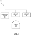
- FIG. 1 schematically illustrates a system 15 for identifying cargo 100.
- Sensors 40 are positioned to detect cargo 100.
- Each of the sensors 40 is configured to detect a different aspect of the cargo 100, such as but not limited to position, RFID, and visual identification code.
- a computing device 20 receives signals from the sensors 40 indicative of the sensed aspect.
- the computing device 20 determines an initial identity of the cargo 100 based on the signals from the sensor 40. When the initial identities are consistent between the different sensors 40, the computing device 20 identifies the cargo as the initial identify. When the initial identities are inconsistent, the computing device 20 identifies the cargo in a different manner. In some examples, the computing device 20 identifies the cargo based on a hierarchy of the different aspects that are sensed by the sensors 40.
- the cargo 100 can include a wide variety of items that can be stored in a wide variety of packaging.
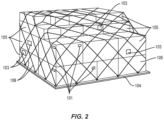
- Figure 2 includes an example of cargo 100 that includes a pallet base 104 that supports individual packages 105.
- a protective material such as plastic sheeting is wrapped around the packages 105 for protection.
- Netting 106 or other like covering material can extend over the packages 105 to attach them to the pallet base 104.
- the packages 105 may be stacked on the pallet base 104 into a shape that conforms to the shape and/or size of the storage location.
- the system 15 can be used in a variety of different contexts.
- One context includes use for loading and/or unloading a vehicle 110.
- the system 15 can be integrated into the vehicle 110 or can be positioned in proximity to the vehicle 110 to monitor cargo 100 moving into and out of the vehicle 110.
- Figure 3 illustrates a specific example in which the vehicle 110 is an aircraft.
- the vehicle 110 includes a fuselage 111 with an interior space 112 configured to hold the cargo 100.
- One or more doors 113 provide for loading and unloading the cargo relative to the interior space 112.
- Sensors 40 are positioned on the vehicle 110 to capture images of the cargo 100 as it is being moved through a door 113.
- the sensors 40 are mounted to the vehicle 110 at various locations, including on one or more of the doors 113, on the fuselage 111, and within the interior space 112. The number of sensors 40 that sense the cargo 100 can vary.
- Figure 4 illustrates the interior space 112 within the fuselage 111.
- the interior space 112 includes a floor 117 that divides the interior space 112 into a main deck 118 above the floor 117 and a lower lobe 119 below the floor 117.
- the cargo 100 is sized to conform to the shape of the interior space 112.
- cargo 100 that includes a pallet base 104 and packages 105 are loaded in the main deck 118.
- Various other cargo is loaded in the lower lobe 119.
- cargo 100 that includes a pallet base 104 and packages 105 is loaded in the lower lobe 119.
- Figure 5 illustrates the interior space 112 of a main deck 118 of an aircraft.
- An alignment area 114 is positioned adjacent to the door 113.
- the cargo 100 is moved through the door 113 and into the alignment area 114 where it is aligned along one of the lanes 115 that extend along the interior space 112.
- the cargo 100 is then moved down the applicable lane 115 for positioning at one of the storage positions 120 for transport.
- lanes 115 can be arranged in front of the alignment area 114 (fore lanes 115) and behind the alignment area 114 (aft lanes 115).
- the aircraft includes six lanes 115 that can be arranged in various configurations.
- the lanes 115 can be arranged in pairs with a right lane and a left lane 115.
- the lanes 115 can also be arranged with a single central lane 115.
- Figure 5 includes a configuration in which a fore section of the main deck 118 includes paired left and right lanes and the aft section includes a single central lane 115.
- Each lane 115 includes storage positions 120 where the cargo 100 is stored during transport.
- the fore section includes two pairs of lanes 115 with storage positions 1R-7R along the right lane 115 and storage positions 1L-7L along the left lane 115.
- the aft section includes a single lane 115 with storage positions 1C-3C. The number and size of the storage positions 120 along the lanes 115 can vary.
- the cargo 100 is positioned within the interior space 112 according to a loading instruction report.
- the loading instruction report includes the storage position 120 for each piece of cargo 100.
- the loading instruction report ensures that the weight of the cargo 100 is distributed about the interior space 112 to provide for a safe flight.
- the report can also facilitate access to the cargo 100 for loading and/or unloading. For example, cargo 100 that is to be removed after transport to an intermediate location is placed closer to the end of the of lane 115 than cargo 100 that is to remain on the vehicle 110 until reaching its final destination.
- the computing device 20 stores the loading instruction report and/or otherwise can access the report.
- the loading instruction report includes the identification of the cargo 100 that includes but is not limited to a description of the packages 105, identification number, weight, dimensions, owner name, owner address, origination point, destination point, destination address, pallet base identification, and identification of the packages 105.
- the loading instructions report also includes the storage position 120 within the interior space 112 where the cargo 100 is to be stored during transport.
- the sensing system 15 is configured to sense and identify the cargo 100.
- the cargo identification is based on identifying the pallet base 104.
- the one or more sensors 40 identify the pallet base 104.
- one or more sensors 40 are cameras that capture one or more images of the cargo 100.
- the cameras include a lens to focus the light and are configured to have one or more shutter speeds. Additionally or alternatively, the cameras include a polarizer to mitigate glare from a bright light source (e.g., sunlight/headlights).
- the cameras 70 are passive cameras that do not include active energy such as lasers. The passive cameras make it more suitable for deployment and operation at airports that have restrictive requirements. The cameras can capture single images and/or video that includes multiple images.
- the cameras include a fixed field of view. This provides for sequences of timed images that include the cargo 100 moving across the field of view. This provides for capturing the cargo 100 from different perspectives and provides for determining a direction of movement of the cargo 100.
- One manner in which the sensing system 15 identifies the cargo 100 is based on the storage position 120 within the interior space 112. Cameras are positioned at one or more locations to determine where the cargo 100 is positioned. Positions for the cameras include one or more of at the door 113, within the alignment area 114, and along lanes 115. In some examples, including the example as illustrated in Figure 5 , a camera detects the position of the cargo 100 within the alignment area 114 including the alignment with one of the lanes 115. In some examples, the computing device 20 determines that cargo 100 will be moved down a lane 115 when placed in the alignment area 114 at the top of the lane 115.
- the lane 115 is determined by computing device 20 after detecting the cargo 100 moving down the particular lane 115.
- the movement is determined using a fixed field of vision camera that captures images over a period of time.
- one or more sensors 40 detect that cargo 100 is initially aligned with a lane and then begins to move down the lane.
- movement sensors 116 are positioned along the floor of the interior space 112 to facilitate movement of the cargo 100.
- movement sensors 116 detect rotation of rollers that are mounted on the floor and facilitate movement of the cargo.
- movement sensors 116 include placement sensors that determine the specific position of the cargo 100.
- the placement sensors emit light beams that are broken by the cargo 100 as they move at particular locations within the interior space 112. The movement sensors 116 provide for the computing device 20 to determine the specific position of the cargo 100 along a lane 115, such as when the storage position 120 is distanced away from a lane end or other cargo 100.
- the computing device 20 determines that the cargo 100 moves into the lane 115 to a storage position 120. In some examples, the computing device 20 assumes that the cargo 100 will be moved down the lane 115 until it reaches the end of the lane 115 or is positioned against other cargo 100 already loaded into the lane 115. In some examples, the computing device 20 relies on images from the one or more sensors indicating the storage position 120.
- the computing device 20 uses the storage position 120 with the loading instruction report to identify the cargo 100.
- the computing device 20 determines the storage position 120 from the one or more sensors 40 and the identification for that position from the loading instruction report. For example, the computing device 20 determines the cargo 100 is positioned in the fore section of the interior space within lane 2, space 5R. The computing device 20 then determines that the loading instruction report has a pallet of shoes from XYZ, Inc. at this location.
- the identification system 15 identifies the cargo 100 through radio frequency identification (RFID).
- RFID radio frequency identification
- the sensor 40 is an RFID reader that interacts with an RFID tag 101 that is attached to the pallet base 104 of the cargo 100.
- the sensor 40 includes one or more antennas 42 for transmitting and/or receiving signals.
- the RFID reader transmits a signal (e.g., activation signal) that is generally at a specific frequency that is within a range that will cause the RFID tag 101 to resonate.
- the signal may also be transmitted at a specific power.
- the RFID tag 101 receives the signal and resonates and transmit a signal that can is received by the antenna 42.
- the signal may be an amplitude shift keying (ASK) modulated signal, a phase shift keying (PSK) modulated signal, or other type of modulated signal.
- the signal indicates one or more aspects of the cargo 100 to provide for identification. Examples of aspects include but are not limited to a serial number, shipping number, name of the goods, owner name, destination, and address.
- the RFID tag 101 is active and includes a power source to transmit the signals.
- the RFID tag 101 transmits the signals in response to receiving a transmission from the RFID reader and/or can transmit signals are various times.
- the sensor 40 is a reader configured to detect an optical code 103 on the pallet base 104 of the cargo 100.
- the optical code 103 can include various formats, including but not limited to a QR code, a bar code, and one or more alphanumeric characters (e.g., letters and numbers that form a serial number).
- the optical code 103 is configured to include one or more aspects about the cargo 100 that is used to determine the identification.
- the reader can include various formats, including but not limited to a camera and a scanner. In some examples, the reader is the same camera used to capture images of the cargo 100 as described above.
- Figure 7 illustrates a method performed to identify the cargo 100.
- the method includes determining initial identifications of the cargo 100 based on different aspects that are sensed by one or more sensors 40 (block 150).
- the computing device 20 compares the initial identifications (block 151).
- the final identification is the same as the initial identifications when the initial identifications are consistent (block 152).
- the final identification is one of the initial indications with the highest hierarchy when the initial identifications are inconsistent (block 154).
- the hierarchy includes whether there is a match from two or more of the different sensors 40.
- the matching identifications are determined to be the correct identification of the cargo 100. For example, readings from a first sensor 40 result in the identification being a first pallet base 104a. Readings from each of a second sensor 40 and a third sensor 40 result in the identification of the cargo as a second pallet base 104b.
- the hierarchy results in the final determination being the matching identification from the two different sensors 40 (in this example, the identification is the second pallet base 104b as determined through the readings from the second and third sensors 40).
- the hierarchy is based on the particular type of sensors 40 and/or data that is captured by the sensor 40. This hierarchy is based on the testing results that show identification through particular sensors to be more accurate than others.
- the hierarchy includes an upper level of identification through an optical code 103, a second level of identification through an RFID tag 101, and then followed by a third level of identification through the storage position and corresponding look-up of the loading instruction report and corresponding identification.
- the system 15 senses three different aspects including an RFID, a storage position 120 within a vehicle 110, and an optical code 103.
- the computing device 20 determines a different identification for each of the three sensed aspects. Because the inconsistencies between three identifications, the computing device 20 determines the final identification based on a hierarchy of aspects. In this and certain other examples, the computing device 20 identifies the cargo 100 based on the optical code 103 because of the hierarchy.
- the system 15 senses three different aspects including an RFID, a placement of the cargo 100 within a vehicle 110, and an optical code 103.
- the computing device 20 determines the same identification based on two of the sensor inputs and a different identification based on a third one of the sensor inputs.
- the hierarchy results in the final identification being the identification from the two sensors that result in the same outcome.
- the system 15 is also configured to save an image of the cargo 100 with the determined identification.
- This pairing of the image with the identified cargo 100 provides for various advantages including but not limited to analyzing the cargo 100 (e.g., how efficiently are the packages 105 positioned on the pallet base 104) and locating the cargo 100 during transport. In some examples, the pairing saves the image of the cargo 100 with the loading instruction report.
- Figure 8 includes one example of identifying and pairing the information.
- An image of the cargo 100 is captured by one or more sensors 40 (block 170). In some examples, this includes capturing an image of the cargo 100 while it is being loaded onto the vehicle 110. Other examples include the one or more images being captured at different times during the loading process.
- the cargo 100 is identified based on one or more inputs from one or more sensors 40 (block 172). Once the cargo 100 is identified, the one or more images of the cargo 100 are paired with the identification (block 174). This pairing is then saved for subsequent use (block 176).
- the pairing method include identifying the cargo 100 based on a RFID tag 101 attached to the pallet base 104.
- the one or more images that are captured of the cargo 100 are then paired with the identified cargo 100.
- This paired information is stored such as at the computing device 20 or other location.
- the image that is saved shows the cargo 100 at the storage position 120 within the vehicle 110 and is saved with the loading instruction report. This information can then be used later in the event there is an issue with the cargo 100.
- the images can be paired with the identified cargo 100.
- the images are individual photos or videos of the cargo 100.
- the images are captured by one or more different sensors 40.
- the captured images are 3D scans of the cargo 100 using various technologies.
- the system 15 can verify that the cargo 100 has been moved to the correct storage position 120 within the vehicle 110.
- the verification process includes identifying the cargo 100 using an identification based on the storage position 120 in combination with one or more additional identifications through one or more other sensors 40.
- the verification process is used to confirm that cargo 100 has been loaded onto a vehicle 110 (e.g., aircraft) according to a loading instruction report.
- Figure 9 illustrates a verification process that includes receiving signals from a first sensor (block 300) that detects the cargo 100 and determining a first identification of the cargo 100 (block 302).
- This first sensor 40 does not rely on the storage position identification, but rather from a different type of identification such as but not limited to an optical code 103 or an RFID tag 101 that is mounted on the pallet base 104.
- the process also includes receiving a signal from a second sensor 40 (block 304) and determining the storage position 120 of the cargo 100 (block 306).
- the computing device 20 receives a signal from a camera and then determines a storage position 120 of the cargo 100 based on the detected location of the cargo 100.
- the computing device 20 determines the identification of the cargo 100 based on the loading instruction report (block 308). This includes looking up the identification from the expected cargo 100 that is to be positioned at the determined storage position 120.
- the computing device 20 compares the two identifications (block 310). When the identifications match, the computing device 20 determines that the cargo 100 has been located at the correct storage position 120 (block 312). When the identifications do not match, the computing device 20 determines that there is an issue because the cargo 100 has not been located at the correct storage position 120 and in response sends a notification (block 314).
- the notifications indicating that the storage position of the cargo 100 does not match the loading instruction report can have various formats and can be sent at various times. Notifications can be sent to one or more of the persons responsible for the loading process, the airline, and the flight crew operating the vehicle 110. Additionally or alternatively, an indicator such as a light or siren can be activated within the environment of the vehicle 110 indicating to those loading that there is a discrepancy.
- the computing device 20 sends a notification at the time the inconsistency is detected. For example, once cargo 100 is positioned at the storage position 120, the computing device 20 sends a notification of the inconsistency. This provides for persons loading the vehicle 110 to address the issue prior to loading additional cargo 100. In other examples, the computing device 20 monitors the loading the cargo 100 onto the aircraft 110. At the end of the loading process, the computing device 20 prepares a report indicating the detected positions of the cargo 100. The report also includes any inconsistencies between the detected storage positions and the corresponding positions indicated on the loading instruction report.
- the identification of the cargo 100 is based on information that is maintained on the pallet base 104. Examples include but are not limited to an RFID tag 101 and/or optical code 103 that is attached to the pallet base 104. In some examples, there is no identifying information on the pallet base 104. This can occur when identification is inadvertently left off the pallet base 104 or the wrong identifying information is attached. This can also occur when the identification on the pallet base 104 is damaged during handling such as an optical code 103 that is scratched off or an RFID tag 101 that is broken and unable to convey information. In some examples, the identification of the cargo 100 is based on identifying one or more of the packages 105 stored on the pallet base 104. As illustrated in Figure 2 , the packages 105 include identifiers, such as an RFID tag 101 or an optical code 103.
- Figure 10 illustrates a method of identifying the cargo 100 based on the identifiers on the packages 105.
- the process initially determines whether there is identification information available on the pallet base 104 (block 400). When information is available, the information is captured and the cargo 100 is identified based on the information (block 402).
- the information is not available from the pallet base 104, information is obtained from one or more of the packages 105 on the pallet base 104 (block 404).
- one or more of the packages 105 include an identifier such as an RFID tag 101 or optical code 103.
- the cargo 100 is then identified based on the one or more identifiers (block 406).
- the information from the packages 105 identifies the cargo 100.
- an RFID tag 101 includes the name of the cargo 100.
- the identification from the packages 105 are compared to the data in the loading instruction report.
- the computing device 20 then identifies the cargo 100 based on the corresponding data from the report.
- the package identifier identifies the package as furniture model number 1234 from ABC Corp.
- the computing device 20 determines that this package 105 is part of a particular cargo 100.
- a confidence value is assigned to the cargo identification.
- the confidence value is the confidence that the cargo 100 was correctly identified. In some examples, this confidence value is stored with the identification and one or more images. In some examples, the confidence value is stored with the loading instruction report.
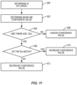
- Figure 11 illustrates a method of determining a confidence value for cargo 100.
- the cargo 100 is identified based on a sensed aspect (block 500).
- the cargo 100 is identified based on one of the RFID, optical code 103, or storage position 120.
- a baseline confidence value is determined for the identification (block 502).
- the baseline confidence value is the same for each type of identification.
- the baseline confidence value is based on the manner of identification.
- the baseline uses the hierarchy.
- a highest baseline e.g., 80%
- an intermediate baseline e.g., 70%
- a lowest value e.g., 60%
- the method determines if there are other identifications based on other detected aspects (block 504). If there are no other identifications, the initial baseline confidence is assigned to the identification (block 506). If there is another identification, the computing device 20 determines if the different identifications match (block 508). If the identifications match, then the confidence value assigned is increased (block 510). If the identifications do not match, the confidence value is decreased (block 512). For example, an initial confidence value of 75% is assigned for a first identification based on a storage position 120. A second identification is also made for the cargo 100 based on RFID. If the identifications match, the confidence value for the identification is raised to 90%. If the identifications are different, the confidence value for the cargo is lowered to 60%. The confidence value for an identification can be increased or decreased for each sensed identification.
- the vehicle 110 is not able to leave the loading area until a review of the actual loading is compared with the loading instruction report.
- the review ensures that the cargo 100 is loaded at the proper locations within the interior space 112 in accordance with the loading instruction report.
- the loading process is finalized and the vehicle 110 can leave the loading area and begin travel.
- the vehicle 110 is prevented from leaving when there is an inconsistency between the placement of the cargo 100 and the loading instruction report.
- the placement of the cargo 100 is carefully controlled to distribute the weight. Placement contrary to the loading instruction report could cause a change in the distribution and thus be an issue during a flight.
- the descriptions above have described the system 15 for use in loading and unloading a vehicle 110, such as an aircraft.
- the system 15 is also applicable for use in other contexts. Some examples include but are not limited to use within a manufacturing facility where the packages 105 are manufactured and/or packaged, a warehouse where the cargo 100 is stored, and a transportation environment such as at an airport, dock, warehouse wherein the goods are moved prior to being loaded onto a vehicle.
- Figure 12 schematically illustrates a computing device 20 configured to identify the cargo 100.
- the computing device 20 includes processing circuitry 21, memory circuitry 22, sensor interface circuitry 23, and communications circuitry 24.
- the processing circuitry 21 controls overall operation of the system 15 according to program instructions 80 stored in the memory circuitry 22.
- the processing circuitry 21 includes one or more circuits, microcontrollers, microprocessors, hardware, or a combination thereof.
- the processing circuitry 21 can include various amounts of computing power to provide for the needed functionality.
- Memory circuitry 22 includes a non-transitory computer readable storage medium storing program instructions, such as a computer program product, that configures the processing circuitry 21 to implement one or more of the techniques discussed herein.
- Memory circuitry 22 can include various memory devices such as, for example, read-only memory, and flash memory.
- Memory circuitry 22 can be a separate component as illustrated in Figure 12 or can be incorporated with the processing circuitry 21.
- the processing circuitry 21 can omit the memory circuitry 22, e.g., according to at least some examples in which the processing circuitry 21 is dedicated and non-programmable.
- the memory circuitry 22 is configured to store information about the cargo 100. In some examples, this includes the loading instruction report. The same and/or additional information related to the cargo 100 can further be stored, including but not limited to the shape, size weight, contents, particular shipping instructions, origination point, and destination point, and storage position.
- the sensor interface circuitry 23 provides for receiving signals from the sensors 40.
- the sensor interface circuitry 23 can provide for one-way communications from the sensors 40 or two-way communications that are both to and from the sensors 40.
- the communications can be through wireless and/or wired means. In some examples, the communications occur through a communication system that is already established on the vehicle 110.
- the communication circuitry 24 provides for communications to and from the computing device 20.
- the communications can include communications with other circuitry on the vehicle 110 (e.g., vehicle control system) and/or communications with a remote node 99.
- Communications circuitry 24 provides for sending and receiving data with one or more remote nodes 99.
- a user interface 28 provides for a user to access data about the cargo 100.
- the user interface 28 can include one or more input devices 27 such as but not limited to a keypad, touchpad, roller ball, and joystick.
- the user interface 28 can also include one or more displays 26 for displaying information to regarding the cargo 100 and/or for an operator to enter commands to the processing circuitry 21.
- the computing device 20 operates autonomously to process the signals and identify the cargo 100.
- the final identification of the cargo 100 can be output to one or more remote nodes. This autonomous ability minimizes and/or eliminates operator intervention which could slow the process and/or create errors.
- the entire system 15 is integrated with the vehicle 110.
- the computing device 20 can be a stand-alone device that provides just for the computation of the cargo 100. In some examples, the computing device 20 performs one or more additional functions.
- the computing device 20 can be part of the flight control computer that oversees the operation of the vehicle 110. In other examples, the computing device 20 is part of a loading system that comprises sensors 40 located throughout the vehicle 110 and is used for monitoring passengers and/or cargo 100.
- the computing device 20 is located remotely from the vehicle 110. Some examples include the computing device 20 being a remote node 99 that receives the images from the sensors 40 and processes the data to determine the final identification.
- the computing device 20 is configured to access information about the cargo 100 that is stored remotely at one or more remote nodes 99. In some examples, the computing device 20 accesses a node 99 to obtain the loading instruction report.
- the computing device 20 receives the signals from the sensors 40.
- the computing device 20 is configured to use a combination of machine learned perception, photogrammetry, and automated software modules to automatically process and deliver data in real time.
- the computing device 20 is configured to process the data in a timely manner which can range from minutes to hours depending upon the amount of data and the needed parameters of the job.
- a system to identify cargo (100) comprising: a first sensor (40) configured to sense a first aspect of the cargo (100); a second sensor (40) configured to sense a different second aspect of the cargo (100); a computing device (20) configured to: determine a first initial identification of the cargo (100) based on signals from the first sensor (40); determine a second initial identification of the cargo (100) based on signals from the second sensor (40); identify the cargo (100) in a first manner when the first initial identification matches the second initial identification; and identify the cargo (100) in a second manner when the first initial identification is different than the second initial identification.
- Clause 2 The system of Clause 1, wherein the computing device (20) is further configured to pair an image of the cargo (100) with a final identification.
- Clause 3 The system of Clause 1 or 2, wherein the first manner comprises determining a final identification of the cargo (100) as the first initial identification.
- Clause 4 The system of any of Clauses 1 to 3, wherein the first sensor (40), the second sensor (40), and the computing device (20) are mounted on an aircraft.
Landscapes
- Engineering & Computer Science (AREA)
- Business, Economics & Management (AREA)
- Theoretical Computer Science (AREA)
- General Physics & Mathematics (AREA)
- Physics & Mathematics (AREA)
- Economics (AREA)
- Computer Vision & Pattern Recognition (AREA)
- Multimedia (AREA)
- Marketing (AREA)
- Human Resources & Organizations (AREA)
- General Business, Economics & Management (AREA)
- Tourism & Hospitality (AREA)
- Development Economics (AREA)
- Strategic Management (AREA)
- Operations Research (AREA)
- Entrepreneurship & Innovation (AREA)
- Quality & Reliability (AREA)
- Medical Informatics (AREA)
- Computing Systems (AREA)
- Health & Medical Sciences (AREA)
- Software Systems (AREA)
- General Health & Medical Sciences (AREA)
- Evolutionary Computation (AREA)
- Databases & Information Systems (AREA)
- Artificial Intelligence (AREA)
- Aviation & Aerospace Engineering (AREA)
- Finance (AREA)
- Accounting & Taxation (AREA)
- General Engineering & Computer Science (AREA)
- Management, Administration, Business Operations System, And Electronic Commerce (AREA)
- Warehouses Or Storage Devices (AREA)
- Geophysics And Detection Of Objects (AREA)
Abstract
A system to identify cargo. The system includes sensors that detect different aspects of the cargo. A computing device receives signals from the sensors indicative of the sensed aspects. The computing device determines an initial identity of the cargo based on the signals from the sensors. When the initial identities are consistent between the different sensors, the computing device identifies the cargo as the initial identify. When the initial identities are inconsistent, the computing device identifies the cargo in a different manner.
Description
- The present disclosure relates generally to the field of cargo identification and, more specifically, to identifying cargo based on inputs from multiple different sensors.
- Packaging and moving cargo are fundamental aspects of today's world. The cargo can include a wide variety of goods and include a wide variety of packaging. Various methods have been developed to identify cargo. Some examples include vision systems that capture images of the cargo which are then analyzed to identify the cargo. Another example includes a radio-frequency identification (RFID) tag that is placed on the cargo. Information from the RFID tag is read to identify the cargo. Another example includes an identification code, such as a quick response (QR) code, bar code, or shipping label that can be read from the cargo and used for the identification.
- An issue with current methods is that each of the various identification methods have drawbacks that may prevent accurate identification. Vision systems can be inaccurate, especially when the images of the cargo are not clear, such as when the cargo is obscured by other items. RFID tags can be broken during shipping and prevent use. Identification codes can be damaged during cargo handling and prevent the identification.
- Some systems include a manually identification in which one or more persons identify the cargo. The identification can be based on some type of label on the cargo itself and/or based on a shipping manifest. The identification is then manually input into a computer system. Manual identification is a tedious process that is often time-consuming and not practical for systems that have tight timing deadlines. Further, manual systems also have inaccuracies caused by the difficulty with the persons involved properly identifying the cargo and then accurately inputting the identification into the computer system.
- Systems and method are needed to provide for accurate identification of the cargo, particularly during movement of the cargo.
- There is described herein a system to identify cargo. The system comprises one or more sensors configured to sense different aspects of the cargo and to transmit signals corresponding to the aspect. A computing device receives the signals from the one or more sensors. The computing device is configured to: determine initial identifications of the cargo based on the aspects that are sensed by the one or more sensors; when the initial identifications match, determine that a final identification of the cargo is equal to the initial identifications; and when the initial identifications do not match, determine the final identification based on a hierarchy of the initial identifications.
- The computing device may be further configured to pair an image of the cargo with the final identification. The image of the cargo may be one or more 3D scans of the cargo.
- The computing device may be further configured to determine a confidence value of the final identification of the cargo and pair the confidence value with the final identification. The computing device may be further configured to determine the confidence value based on a first one of the initial identifications of the cargo and determine that the first one of the initial identifications matches a second one of the initial identifications and increase the confidence value. The computing device may be further configured to determine that the first one of the initial identifications of the
cargo 100 is different than a third one of the initial identifications and decrease the confidence value. - One of the sensors may comprise a camera and the aspect is a storage position of the cargo. One of the sensors may comprise a RFID reader and the aspect is a predetermined identification that is stored in an RFID tag that is mounted on the cargo. One of the
sensors 40 may comprise an optical reader and the aspect is an optical code that is on the cargo. The sensors and the computing device may be mounted on a vehicle. - The computing device may be configured to: determine a storage position of the cargo based on an image of the cargo; determine a description for the storage position from a loading instructions report; and determine the identification of the cargo as the description. The computing device may be configured to: determine a first identification of the cargo based on an image of the cargo captured by a camera; determine a second identification of the cargo based on an optical code on the cargo; and determine that the first identification and the second identification match and that the final identification is the first identification and the second identification. The computing device may be further configured to: determine a position of cargo within an alignment area; determine a lane in which the cargo is moved based on the position within the alignment area; and determine a storage position based on the lane.
- There is described herein a system to identify cargo. The system comprises a first sensor configured to sense a first aspect of the cargo and a second sensor configured to sense a different second aspect of the cargo. A computing device is configured to: determine a first initial identification of the cargo based on signals from the first sensor; determine a second initial identification of the cargo based on signals from the second sensor; identify the cargo in a first manner when the first initial identification matches the second initial identification; and identify the cargo in a second manner when the first initial identification is different than the second initial identification.
- The computing device may be further configured to pair an image of the cargo with a final identification. The first manner may comprise determining a final identification of the cargo as the first initial identification. The first sensor, the second sensor, and the computing device may be mounted on an aircraft.
- There is described herein a method of identifying cargo. The method comprises: determining initial identifications of the cargo based on different aspects that are sensed by one or more sensors; comparing the initial identifications; determining that a final identification of the cargo is the same as the initial identifications when the initial identifications match; and determining a confidence value of the final identification.
- The method may further comprise capturing an image of the cargo and pairing the image with the final identification. Determining the confidence value may comprise determining a baseline value based on first one of the initial identifications and increasing the baseline value based on a second one of the initial identifications matching the first one of the initial identifications.
- The features, functions and advantages that have been discussed can be achieved independently in various examples or may be combined in yet other examples, further details of which can be seen with reference to the following description and the drawings.
-
-
Figure 1 is a schematic diagram of a system for identifying cargo. -
Figure 2 is a perspective view of cargo that includes a pallet base with stacked packages that are held with netting. -
Figure 3 is a schematic diagram of a vehicle equipped with a system configured to identify cargo that is being loaded and unloaded. -
Figure 4 is a section view of the fuselage of the aircraft cut along line IV-IV ofFigure 3 . -
Figure 5 is a schematic diagram of an interior space of a vehicle configured to store the cargo during transport. -
Figure 6 is a schematic diagram of an identification system that includes sensors configured to detect cargo and a computing device that receives signals from the sensors. -
Figure 7 is a flowchart diagram of a method of identifying cargo. -
Figure 8 is a flowchart diagram of a method of pairing a captured image of the cargo with a identification. -
Figure 9 is a flowchart diagram of a method of determining placement of the cargo. -
Figure 10 is a flowchart diagram of a method of determining an identification of cargo based on identifications of one or more packages in the cargo. -
Figure 11 is a flowchart diagram of a method of determining a confidence value of an identification of cargo. -
Figure 12 is a schematic diagram of a computing device. -
Figure 1 schematically illustrates asystem 15 for identifyingcargo 100.Sensors 40 are positioned to detectcargo 100. Each of thesensors 40 is configured to detect a different aspect of thecargo 100, such as but not limited to position, RFID, and visual identification code. Acomputing device 20 receives signals from thesensors 40 indicative of the sensed aspect. Thecomputing device 20 determines an initial identity of thecargo 100 based on the signals from thesensor 40. When the initial identities are consistent between thedifferent sensors 40, thecomputing device 20 identifies the cargo as the initial identify. When the initial identities are inconsistent, thecomputing device 20 identifies the cargo in a different manner. In some examples, thecomputing device 20 identifies the cargo based on a hierarchy of the different aspects that are sensed by thesensors 40. - The
cargo 100 can include a wide variety of items that can be stored in a wide variety of packaging.Figure 2 includes an example ofcargo 100 that includes apallet base 104 that supportsindividual packages 105. A protective material (not illustrated) such as plastic sheeting is wrapped around thepackages 105 for protection. Netting 106 or other like covering material can extend over thepackages 105 to attach them to thepallet base 104. Thepackages 105 may be stacked on thepallet base 104 into a shape that conforms to the shape and/or size of the storage location. - The
system 15 can be used in a variety of different contexts. One context includes use for loading and/or unloading avehicle 110. Thesystem 15 can be integrated into thevehicle 110 or can be positioned in proximity to thevehicle 110 to monitorcargo 100 moving into and out of thevehicle 110.Figure 3 illustrates a specific example in which thevehicle 110 is an aircraft. Thevehicle 110 includes afuselage 111 with aninterior space 112 configured to hold thecargo 100. One ormore doors 113 provide for loading and unloading the cargo relative to theinterior space 112.Sensors 40 are positioned on thevehicle 110 to capture images of thecargo 100 as it is being moved through adoor 113. Thesensors 40 are mounted to thevehicle 110 at various locations, including on one or more of thedoors 113, on thefuselage 111, and within theinterior space 112. The number ofsensors 40 that sense thecargo 100 can vary. -
Figure 4 illustrates theinterior space 112 within thefuselage 111. Theinterior space 112 includes afloor 117 that divides theinterior space 112 into amain deck 118 above thefloor 117 and alower lobe 119 below thefloor 117. Thecargo 100 is sized to conform to the shape of theinterior space 112. In some examples as illustrated inFigure 4 ,cargo 100 that includes apallet base 104 andpackages 105 are loaded in themain deck 118. Various other cargo is loaded in thelower lobe 119. In other examples,cargo 100 that includes apallet base 104 andpackages 105 is loaded in thelower lobe 119. -
Figure 5 illustrates theinterior space 112 of amain deck 118 of an aircraft. Analignment area 114 is positioned adjacent to thedoor 113. Thecargo 100 is moved through thedoor 113 and into thealignment area 114 where it is aligned along one of thelanes 115 that extend along theinterior space 112. Thecargo 100 is then moved down theapplicable lane 115 for positioning at one of the storage positions 120 for transport. - As illustrated in
Figure 5 ,lanes 115 can be arranged in front of the alignment area 114 (fore lanes 115) and behind the alignment area 114 (aft lanes 115). In one example, the aircraft includes sixlanes 115 that can be arranged in various configurations. Thelanes 115 can be arranged in pairs with a right lane and aleft lane 115. Thelanes 115 can also be arranged with a singlecentral lane 115.Figure 5 includes a configuration in which a fore section of themain deck 118 includes paired left and right lanes and the aft section includes a singlecentral lane 115. - Each
lane 115 includesstorage positions 120 where thecargo 100 is stored during transport. UsingFigure 5 as an example, the fore section includes two pairs oflanes 115 withstorage positions 1R-7R along theright lane 115 andstorage positions 1L-7L along theleft lane 115. The aft section includes asingle lane 115 withstorage positions 1C-3C. The number and size of the storage positions 120 along thelanes 115 can vary. - In some examples, the
cargo 100 is positioned within theinterior space 112 according to a loading instruction report. The loading instruction report includes thestorage position 120 for each piece ofcargo 100. The loading instruction report ensures that the weight of thecargo 100 is distributed about theinterior space 112 to provide for a safe flight. The report can also facilitate access to thecargo 100 for loading and/or unloading. For example,cargo 100 that is to be removed after transport to an intermediate location is placed closer to the end of the oflane 115 thancargo 100 that is to remain on thevehicle 110 until reaching its final destination. - The
computing device 20 stores the loading instruction report and/or otherwise can access the report. The loading instruction report includes the identification of thecargo 100 that includes but is not limited to a description of thepackages 105, identification number, weight, dimensions, owner name, owner address, origination point, destination point, destination address, pallet base identification, and identification of thepackages 105. The loading instructions report also includes thestorage position 120 within theinterior space 112 where thecargo 100 is to be stored during transport. - The
sensing system 15 is configured to sense and identify thecargo 100. In some examples, the cargo identification is based on identifying thepallet base 104. The one ormore sensors 40 identify thepallet base 104. - In some examples, one or
more sensors 40 are cameras that capture one or more images of thecargo 100. The cameras include a lens to focus the light and are configured to have one or more shutter speeds. Additionally or alternatively, the cameras include a polarizer to mitigate glare from a bright light source (e.g., sunlight/headlights). In some examples, the cameras 70 are passive cameras that do not include active energy such as lasers. The passive cameras make it more suitable for deployment and operation at airports that have restrictive requirements. The cameras can capture single images and/or video that includes multiple images. - In some examples, the cameras include a fixed field of view. This provides for sequences of timed images that include the
cargo 100 moving across the field of view. This provides for capturing thecargo 100 from different perspectives and provides for determining a direction of movement of thecargo 100. - One manner in which the
sensing system 15 identifies thecargo 100 is based on thestorage position 120 within theinterior space 112. Cameras are positioned at one or more locations to determine where thecargo 100 is positioned. Positions for the cameras include one or more of at thedoor 113, within thealignment area 114, and alonglanes 115. In some examples, including the example as illustrated inFigure 5 , a camera detects the position of thecargo 100 within thealignment area 114 including the alignment with one of thelanes 115. In some examples, thecomputing device 20 determines thatcargo 100 will be moved down alane 115 when placed in thealignment area 114 at the top of thelane 115. Additionally or alternatively, thelane 115 is determined by computingdevice 20 after detecting thecargo 100 moving down theparticular lane 115. The movement is determined using a fixed field of vision camera that captures images over a period of time. For example, one ormore sensors 40 detect thatcargo 100 is initially aligned with a lane and then begins to move down the lane. - In some examples,
movement sensors 116 are positioned along the floor of theinterior space 112 to facilitate movement of thecargo 100. In some examples,movement sensors 116 detect rotation of rollers that are mounted on the floor and facilitate movement of the cargo. In other examples,movement sensors 116 include placement sensors that determine the specific position of thecargo 100. In one specific example, the placement sensors emit light beams that are broken by thecargo 100 as they move at particular locations within theinterior space 112. Themovement sensors 116 provide for thecomputing device 20 to determine the specific position of thecargo 100 along alane 115, such as when thestorage position 120 is distanced away from a lane end orother cargo 100. - The
computing device 20 determines that thecargo 100 moves into thelane 115 to astorage position 120. In some examples, thecomputing device 20 assumes that thecargo 100 will be moved down thelane 115 until it reaches the end of thelane 115 or is positioned againstother cargo 100 already loaded into thelane 115. In some examples, thecomputing device 20 relies on images from the one or more sensors indicating thestorage position 120. - The
computing device 20 uses thestorage position 120 with the loading instruction report to identify thecargo 100. Thecomputing device 20 determines thestorage position 120 from the one ormore sensors 40 and the identification for that position from the loading instruction report. For example, thecomputing device 20 determines thecargo 100 is positioned in the fore section of the interior space within lane 2,space 5R. Thecomputing device 20 then determines that the loading instruction report has a pallet of shoes from XYZ, Inc. at this location. - In some examples, the
identification system 15 identifies thecargo 100 through radio frequency identification (RFID). As schematically illustrated inFigure 6 , thesensor 40 is an RFID reader that interacts with anRFID tag 101 that is attached to thepallet base 104 of thecargo 100. Thesensor 40 includes one ormore antennas 42 for transmitting and/or receiving signals. During use, the RFID reader transmits a signal (e.g., activation signal) that is generally at a specific frequency that is within a range that will cause theRFID tag 101 to resonate. The signal may also be transmitted at a specific power. TheRFID tag 101 receives the signal and resonates and transmit a signal that can is received by theantenna 42. The signal may be an amplitude shift keying (ASK) modulated signal, a phase shift keying (PSK) modulated signal, or other type of modulated signal. The signal indicates one or more aspects of thecargo 100 to provide for identification. Examples of aspects include but are not limited to a serial number, shipping number, name of the goods, owner name, destination, and address. - In some examples, the
RFID tag 101 is active and includes a power source to transmit the signals. TheRFID tag 101 transmits the signals in response to receiving a transmission from the RFID reader and/or can transmit signals are various times. - In some examples, the
sensor 40 is a reader configured to detect anoptical code 103 on thepallet base 104 of thecargo 100. Theoptical code 103 can include various formats, including but not limited to a QR code, a bar code, and one or more alphanumeric characters (e.g., letters and numbers that form a serial number). Theoptical code 103 is configured to include one or more aspects about thecargo 100 that is used to determine the identification. The reader can include various formats, including but not limited to a camera and a scanner. In some examples, the reader is the same camera used to capture images of thecargo 100 as described above. -
Figure 7 illustrates a method performed to identify thecargo 100. The method includes determining initial identifications of thecargo 100 based on different aspects that are sensed by one or more sensors 40 (block 150). Thecomputing device 20 compares the initial identifications (block 151). The final identification is the same as the initial identifications when the initial identifications are consistent (block 152). The final identification is one of the initial indications with the highest hierarchy when the initial identifications are inconsistent (block 154). - In some examples, the hierarchy includes whether there is a match from two or more of the
different sensors 40. The matching identifications are determined to be the correct identification of thecargo 100. For example, readings from afirst sensor 40 result in the identification being a first pallet base 104a. Readings from each of asecond sensor 40 and athird sensor 40 result in the identification of the cargo as a second pallet base 104b. The hierarchy results in the final determination being the matching identification from the two different sensors 40 (in this example, the identification is the second pallet base 104b as determined through the readings from the second and third sensors 40). - Additionally or alternatively, the hierarchy is based on the particular type of
sensors 40 and/or data that is captured by thesensor 40. This hierarchy is based on the testing results that show identification through particular sensors to be more accurate than others. In some examples, the hierarchy includes an upper level of identification through anoptical code 103, a second level of identification through anRFID tag 101, and then followed by a third level of identification through the storage position and corresponding look-up of the loading instruction report and corresponding identification. - In some examples, the
system 15 senses three different aspects including an RFID, astorage position 120 within avehicle 110, and anoptical code 103. In this and certain other examples, thecomputing device 20 determines a different identification for each of the three sensed aspects. Because the inconsistencies between three identifications, thecomputing device 20 determines the final identification based on a hierarchy of aspects. In this and certain other examples, thecomputing device 20 identifies thecargo 100 based on theoptical code 103 because of the hierarchy. - In other examples, the
system 15 senses three different aspects including an RFID, a placement of thecargo 100 within avehicle 110, and anoptical code 103. Thecomputing device 20 determines the same identification based on two of the sensor inputs and a different identification based on a third one of the sensor inputs. In some examples, the hierarchy results in the final identification being the identification from the two sensors that result in the same outcome. - The
system 15 is also configured to save an image of thecargo 100 with the determined identification. This pairing of the image with the identifiedcargo 100 provides for various advantages including but not limited to analyzing the cargo 100 (e.g., how efficiently are thepackages 105 positioned on the pallet base 104) and locating thecargo 100 during transport. In some examples, the pairing saves the image of thecargo 100 with the loading instruction report. -
Figure 8 includes one example of identifying and pairing the information. An image of thecargo 100 is captured by one or more sensors 40 (block 170). In some examples, this includes capturing an image of thecargo 100 while it is being loaded onto thevehicle 110. Other examples include the one or more images being captured at different times during the loading process. Thecargo 100 is identified based on one or more inputs from one or more sensors 40 (block 172). Once thecargo 100 is identified, the one or more images of thecargo 100 are paired with the identification (block 174). This pairing is then saved for subsequent use (block 176). - Some examples of the pairing method include identifying the
cargo 100 based on aRFID tag 101 attached to thepallet base 104. The one or more images that are captured of thecargo 100 are then paired with the identifiedcargo 100. This paired information is stored such as at thecomputing device 20 or other location. In some examples, the image that is saved shows thecargo 100 at thestorage position 120 within thevehicle 110 and is saved with the loading instruction report. This information can then be used later in the event there is an issue with thecargo 100. - Various types of captured images can be paired with the identified
cargo 100. In some examples, the images are individual photos or videos of thecargo 100. The images are captured by one or moredifferent sensors 40. In other examples, the captured images are 3D scans of thecargo 100 using various technologies. - The
system 15 can verify that thecargo 100 has been moved to thecorrect storage position 120 within thevehicle 110. The verification process includes identifying thecargo 100 using an identification based on thestorage position 120 in combination with one or more additional identifications through one or moreother sensors 40. In some examples, the verification process is used to confirm thatcargo 100 has been loaded onto a vehicle 110 (e.g., aircraft) according to a loading instruction report. -
Figure 9 illustrates a verification process that includes receiving signals from a first sensor (block 300) that detects thecargo 100 and determining a first identification of the cargo 100 (block 302). Thisfirst sensor 40 does not rely on the storage position identification, but rather from a different type of identification such as but not limited to anoptical code 103 or anRFID tag 101 that is mounted on thepallet base 104. - The process also includes receiving a signal from a second sensor 40 (block 304) and determining the
storage position 120 of the cargo 100 (block 306). For example, thecomputing device 20 receives a signal from a camera and then determines astorage position 120 of thecargo 100 based on the detected location of thecargo 100. Thecomputing device 20 then determines the identification of thecargo 100 based on the loading instruction report (block 308). This includes looking up the identification from the expectedcargo 100 that is to be positioned at thedetermined storage position 120. - The
computing device 20 then compares the two identifications (block 310). When the identifications match, thecomputing device 20 determines that thecargo 100 has been located at the correct storage position 120 (block 312). When the identifications do not match, thecomputing device 20 determines that there is an issue because thecargo 100 has not been located at thecorrect storage position 120 and in response sends a notification (block 314). - The notifications indicating that the storage position of the
cargo 100 does not match the loading instruction report can have various formats and can be sent at various times. Notifications can be sent to one or more of the persons responsible for the loading process, the airline, and the flight crew operating thevehicle 110. Additionally or alternatively, an indicator such as a light or siren can be activated within the environment of thevehicle 110 indicating to those loading that there is a discrepancy. - In some examples, the
computing device 20 sends a notification at the time the inconsistency is detected. For example, oncecargo 100 is positioned at thestorage position 120, thecomputing device 20 sends a notification of the inconsistency. This provides for persons loading thevehicle 110 to address the issue prior to loadingadditional cargo 100. In other examples, thecomputing device 20 monitors the loading thecargo 100 onto theaircraft 110. At the end of the loading process, thecomputing device 20 prepares a report indicating the detected positions of thecargo 100. The report also includes any inconsistencies between the detected storage positions and the corresponding positions indicated on the loading instruction report. - In some examples, the identification of the
cargo 100 is based on information that is maintained on thepallet base 104. Examples include but are not limited to anRFID tag 101 and/oroptical code 103 that is attached to thepallet base 104. In some examples, there is no identifying information on thepallet base 104. This can occur when identification is inadvertently left off thepallet base 104 or the wrong identifying information is attached. This can also occur when the identification on thepallet base 104 is damaged during handling such as anoptical code 103 that is scratched off or anRFID tag 101 that is broken and unable to convey information. In some examples, the identification of thecargo 100 is based on identifying one or more of thepackages 105 stored on thepallet base 104. As illustrated inFigure 2 , thepackages 105 include identifiers, such as anRFID tag 101 or anoptical code 103. -
Figure 10 illustrates a method of identifying thecargo 100 based on the identifiers on thepackages 105. The process initially determines whether there is identification information available on the pallet base 104 (block 400). When information is available, the information is captured and thecargo 100 is identified based on the information (block 402). - When the information is not available from the
pallet base 104, information is obtained from one or more of thepackages 105 on the pallet base 104 (block 404). For example, one or more of thepackages 105 include an identifier such as anRFID tag 101 oroptical code 103. Thecargo 100 is then identified based on the one or more identifiers (block 406). - In some examples, the information from the
packages 105 identifies thecargo 100. For example, anRFID tag 101 includes the name of thecargo 100. In some examples, the identification from thepackages 105 are compared to the data in the loading instruction report. Thecomputing device 20 then identifies thecargo 100 based on the corresponding data from the report. For example, the package identifier identifies the package as furniture model number 1234 from ABC Corp. Thecomputing device 20 determines that thispackage 105 is part of aparticular cargo 100. - In some examples, a confidence value is assigned to the cargo identification. The confidence value is the confidence that the
cargo 100 was correctly identified. In some examples, this confidence value is stored with the identification and one or more images. In some examples, the confidence value is stored with the loading instruction report. -
Figure 11 illustrates a method of determining a confidence value forcargo 100. Initially, thecargo 100 is identified based on a sensed aspect (block 500). For example, thecargo 100 is identified based on one of the RFID,optical code 103, orstorage position 120. A baseline confidence value is determined for the identification (block 502). In some examples, the baseline confidence value is the same for each type of identification. In other examples, the baseline confidence value is based on the manner of identification. In some examples, the baseline uses the hierarchy. In some examples, a highest baseline (e.g., 80%) is assigned for an RFID identification, an intermediate baseline (e.g., 70%) based on astorage position 120, and a lowest value (e.g., 60%) based on anoptical code 103. - The method then determines if there are other identifications based on other detected aspects (block 504). If there are no other identifications, the initial baseline confidence is assigned to the identification (block 506). If there is another identification, the
computing device 20 determines if the different identifications match (block 508). If the identifications match, then the confidence value assigned is increased (block 510). If the identifications do not match, the confidence value is decreased (block 512). For example, an initial confidence value of 75% is assigned for a first identification based on astorage position 120. A second identification is also made for thecargo 100 based on RFID. If the identifications match, the confidence value for the identification is raised to 90%. If the identifications are different, the confidence value for the cargo is lowered to 60%. The confidence value for an identification can be increased or decreased for each sensed identification. - In some examples, the
vehicle 110 is not able to leave the loading area until a review of the actual loading is compared with the loading instruction report. The review ensures that thecargo 100 is loaded at the proper locations within theinterior space 112 in accordance with the loading instruction report. When the placement is consistent with the loading instruction report, the loading process is finalized and thevehicle 110 can leave the loading area and begin travel. Conversely, thevehicle 110 is prevented from leaving when there is an inconsistency between the placement of thecargo 100 and the loading instruction report. In one example in which thevehicle 110 is an aircraft, the placement of thecargo 100 is carefully controlled to distribute the weight. Placement contrary to the loading instruction report could cause a change in the distribution and thus be an issue during a flight. - The descriptions above have described the
system 15 for use in loading and unloading avehicle 110, such as an aircraft. Thesystem 15 is also applicable for use in other contexts. Some examples include but are not limited to use within a manufacturing facility where thepackages 105 are manufactured and/or packaged, a warehouse where thecargo 100 is stored, and a transportation environment such as at an airport, dock, warehouse wherein the goods are moved prior to being loaded onto a vehicle. -
Figure 12 schematically illustrates acomputing device 20 configured to identify thecargo 100. Thecomputing device 20 includesprocessing circuitry 21,memory circuitry 22,sensor interface circuitry 23, andcommunications circuitry 24. - The
processing circuitry 21 controls overall operation of thesystem 15 according toprogram instructions 80 stored in thememory circuitry 22. Theprocessing circuitry 21 includes one or more circuits, microcontrollers, microprocessors, hardware, or a combination thereof. Theprocessing circuitry 21 can include various amounts of computing power to provide for the needed functionality. -
Memory circuitry 22 includes a non-transitory computer readable storage medium storing program instructions, such as a computer program product, that configures theprocessing circuitry 21 to implement one or more of the techniques discussed herein.Memory circuitry 22 can include various memory devices such as, for example, read-only memory, and flash memory.Memory circuitry 22 can be a separate component as illustrated inFigure 12 or can be incorporated with theprocessing circuitry 21. Alternatively, theprocessing circuitry 21 can omit thememory circuitry 22, e.g., according to at least some examples in which theprocessing circuitry 21 is dedicated and non-programmable. - In some examples, the
memory circuitry 22 is configured to store information about thecargo 100. In some examples, this includes the loading instruction report. The same and/or additional information related to thecargo 100 can further be stored, including but not limited to the shape, size weight, contents, particular shipping instructions, origination point, and destination point, and storage position. - The
sensor interface circuitry 23 provides for receiving signals from thesensors 40. Thesensor interface circuitry 23 can provide for one-way communications from thesensors 40 or two-way communications that are both to and from thesensors 40. The communications can be through wireless and/or wired means. In some examples, the communications occur through a communication system that is already established on thevehicle 110. - The
communication circuitry 24 provides for communications to and from thecomputing device 20. The communications can include communications with other circuitry on the vehicle 110 (e.g., vehicle control system) and/or communications with aremote node 99.Communications circuitry 24 provides for sending and receiving data with one or moreremote nodes 99. - A
user interface 28 provides for a user to access data about thecargo 100. Theuser interface 28 can include one ormore input devices 27 such as but not limited to a keypad, touchpad, roller ball, and joystick. Theuser interface 28 can also include one ormore displays 26 for displaying information to regarding thecargo 100 and/or for an operator to enter commands to theprocessing circuitry 21. - In some examples, the
computing device 20 operates autonomously to process the signals and identify thecargo 100. The final identification of thecargo 100 can be output to one or more remote nodes. This autonomous ability minimizes and/or eliminates operator intervention which could slow the process and/or create errors. - In some examples, the
entire system 15 is integrated with thevehicle 110. Thecomputing device 20 can be a stand-alone device that provides just for the computation of thecargo 100. In some examples, thecomputing device 20 performs one or more additional functions. For example, thecomputing device 20 can be part of the flight control computer that oversees the operation of thevehicle 110. In other examples, thecomputing device 20 is part of a loading system that comprisessensors 40 located throughout thevehicle 110 and is used for monitoring passengers and/orcargo 100. - In yet other examples, the
computing device 20 is located remotely from thevehicle 110. Some examples include thecomputing device 20 being aremote node 99 that receives the images from thesensors 40 and processes the data to determine the final identification. - Additionally or alternatively, the
computing device 20 is configured to access information about thecargo 100 that is stored remotely at one or moreremote nodes 99. In some examples, thecomputing device 20 accesses anode 99 to obtain the loading instruction report. - In some examples, the
computing device 20 receives the signals from thesensors 40. Thecomputing device 20 is configured to use a combination of machine learned perception, photogrammetry, and automated software modules to automatically process and deliver data in real time. Thecomputing device 20 is configured to process the data in a timely manner which can range from minutes to hours depending upon the amount of data and the needed parameters of the job. - Further examples are presented in the following clauses.
- Clause 1. A system to identify cargo (100), the system comprising: a first sensor (40) configured to sense a first aspect of the cargo (100); a second sensor (40) configured to sense a different second aspect of the cargo (100); a computing device (20) configured to: determine a first initial identification of the cargo (100) based on signals from the first sensor (40); determine a second initial identification of the cargo (100) based on signals from the second sensor (40); identify the cargo (100) in a first manner when the first initial identification matches the second initial identification; and identify the cargo (100) in a second manner when the first initial identification is different than the second initial identification.
- Clause 2. The system of Clause 1, wherein the computing device (20) is further configured to pair an image of the cargo (100) with a final identification.
- Clause 3. The system of Clause 1 or 2, wherein the first manner comprises determining a final identification of the cargo (100) as the first initial identification.
- Clause 4. The system of any of Clauses 1 to 3, wherein the first sensor (40), the second sensor (40), and the computing device (20) are mounted on an aircraft.
- The present examples are to be considered in all respects as illustrative and not restrictive, and all changes coming within the meaning of the appended claims are intended to be embraced therein.
Claims (15)
- A system to identify cargo (100), the system comprising:one or more sensors (40) configured to sense different aspects of the cargo (100) and to transmit signals corresponding to the aspects; anda computing device (20) that receives the signals from the one or more sensors (40), the computing device (20) configured to:determine initial identifications of the cargo (100) based on the aspects that are sensed by the one or more sensors (40);when the initial identifications match, determine that a final identification of the cargo (100) is equal to the initial identifications; andwhen the initial identifications do not match, determine the final identification based on a hierarchy of the initial identifications.
- The system of claim 1, wherein the computing device (20) is further configured to pair an image of the cargo (100) with the final identification.
- The system of claim 2, wherein the image of the cargo is one or more 3D scans of the cargo (100).
- The system of any preceding claim, wherein:one of the sensors (40) comprises a RFID reader configured to read a predetermined identification that is stored in an RFID tag (101) that is mounted on the cargo (100) and one of the aspects comprises the predetermined identification; and/orone of the sensors (40) comprises an optical reader configured to read an optical code (103) that is on the cargo (100) and one of the aspects comprises the optical code (103).
- The system of any preceding claim, wherein the computing device (20) is further configured to:
determine a confidence value of the final identification of the cargo (100) and pair the confidence value with the final identification. - The system of claim 5, wherein the computing device (20) is further configured to:determine the confidence value based on a first one of the initial identifications of the cargo (100); anddetermine that the first one of the initial identifications matches a second one of the initial identifications and increase the confidence value.
- The system of claim 5 or 6, wherein the computing device (20) is further configured to determine that the first one of the initial identifications of the cargo (100) is different than a third one of the initial identifications and decrease the confidence value.
- The system of any preceding claim, wherein one of the sensors (40) comprises a camera configured to capture a storage position of the cargo (100) and one of the aspects is the storage position of the cargo (100).
- The system of any preceding claim, wherein the computing device (20) is further configured to:determine a position of cargo (100) within an alignment area (114);determine a lane (115) in which the cargo (100) is moved based on the position within the alignment area (114); anddetermine a storage position (120) based on the lane (115).
- The system of any preceding claim, wherein the computing device (20) is configured to:determine a storage position of the cargo (100) based on an image of the cargo (100);determine a description for the storage position from a loading instructions report; anddetermine one of the initial identifications of the cargo (100) as the description.
- The system of any preceding claim, wherein the computing device (20) is configured to:determine a first identification of the cargo (100) based on an image of the cargo (100) captured by a camera;determine a second identification of the cargo based on an optical code on the cargo (100); anddetermine that the first identification and the second identification match and that the final identification is the first identification and the second identification.
- A vehicle (110), optionally an aircraft, comprising the system of any preceding claim, wherein the sensors (40) and the computing device (20) are mounted on the vehicle (110).
- A method of identifying cargo (100), the method comprising:determining initial identifications of the cargo (100) based on different aspects that are sensed by one or more sensors (40);comparing the initial identifications;determining that a final identification of the cargo (100) is the same as the initial identifications when the initial identifications match; anddetermining a confidence value of the final identification.
- The method of claim 13, further comprising capturing an image of the cargo (100) and pairing the image with the final identification.
- The method of claim 13 or 14, wherein determining the confidence value comprises:determining a baseline value based on a first one of the initial identifications; andincreasing the baseline value based on a second one of the initial identifications matching the first one of the initial identifications.
Applications Claiming Priority (1)
| Application Number | Priority Date | Filing Date | Title |
|---|---|---|---|
| US18/176,693 US20240296666A1 (en) | 2023-03-01 | 2023-03-01 | Systems and Methods to Identify Cargo |
Publications (1)
| Publication Number | Publication Date |
|---|---|
| EP4425401A1 true EP4425401A1 (en) | 2024-09-04 |
Family
ID=89619528
Family Applications (1)
| Application Number | Title | Priority Date | Filing Date |
|---|---|---|---|
| EP24151642.6A Pending EP4425401A1 (en) | 2023-03-01 | 2024-01-12 | Systems and methods to identify cargo |
Country Status (5)
| Country | Link |
|---|---|
| US (1) | US20240296666A1 (en) |
| EP (1) | EP4425401A1 (en) |
| CN (1) | CN118586419A (en) |
| AU (1) | AU2023285733A1 (en) |
| CA (1) | CA3223278A1 (en) |
Citations (3)
| Publication number | Priority date | Publication date | Assignee | Title |
|---|---|---|---|---|
| NZ556253A (en) * | 2007-06-29 | 2010-01-29 | Baggage Sortation Man Ltd | Object tracking method and apparatus |
| US20220063901A1 (en) * | 2020-09-02 | 2022-03-03 | Federal Express Corporation | Intelligent equipment security system |
| US20220405704A1 (en) * | 2016-09-08 | 2022-12-22 | Position Imaging, Inc. | System and method of object tracking using weight confirmation |
Family Cites Families (3)
| Publication number | Priority date | Publication date | Assignee | Title |
|---|---|---|---|---|
| EP2665646B1 (en) * | 2011-01-19 | 2018-08-08 | Telair International GmbH | Loading system for an aircraft, and method for conveying a piece of cargo on a cargo deck |
| US11017346B2 (en) * | 2015-02-18 | 2021-05-25 | FedEx Corporate Services, Inc | Methods, apparatus, and systems for generating a content-related notification using a container interface display apparatus |
| US11142342B2 (en) * | 2016-10-26 | 2021-10-12 | The Boeing Company | Intelligent baggage handling |
-
2023
- 2023-03-01 US US18/176,693 patent/US20240296666A1/en active Pending
- 2023-12-14 CA CA3223278A patent/CA3223278A1/en active Pending
- 2023-12-19 AU AU2023285733A patent/AU2023285733A1/en active Pending
-
2024
- 2024-01-12 EP EP24151642.6A patent/EP4425401A1/en active Pending
- 2024-02-29 CN CN202410230383.5A patent/CN118586419A/en active Pending
Patent Citations (3)
| Publication number | Priority date | Publication date | Assignee | Title |
|---|---|---|---|---|
| NZ556253A (en) * | 2007-06-29 | 2010-01-29 | Baggage Sortation Man Ltd | Object tracking method and apparatus |
| US20220405704A1 (en) * | 2016-09-08 | 2022-12-22 | Position Imaging, Inc. | System and method of object tracking using weight confirmation |
| US20220063901A1 (en) * | 2020-09-02 | 2022-03-03 | Federal Express Corporation | Intelligent equipment security system |
Also Published As
| Publication number | Publication date |
|---|---|
| US20240296666A1 (en) | 2024-09-05 |
| AU2023285733A1 (en) | 2024-09-19 |
| CA3223278A1 (en) | 2025-07-02 |
| CN118586419A (en) | 2024-09-03 |
Similar Documents
| Publication | Publication Date | Title |
|---|---|---|
| US12252355B2 (en) | Robotic singulation system sensor | |
| CA3046663C (en) | Automatic truck loading and unloading system | |
| US10083418B2 (en) | Distributed autonomous robot systems and mehtods | |
| US11173602B2 (en) | Training robotic manipulators | |
| WO2021087490A1 (en) | Profiling pallets and goods in a warehouse environment | |
| US11430148B2 (en) | Apparatus and method for pallet volume dimensioning through 3D vision capable unmanned aerial vehicles (UAV) | |
| CN110238078B (en) | Sorting method, device, system and storage medium | |
| US10929810B1 (en) | Bin content imaging and correlation using automated aerial vehicles | |
| US20190108605A1 (en) | Information processing system, information processing apparatus, information processing method, and program | |
| CN108960737A (en) | Warehouse automatic tour inspection system and method based on machine vision | |
| KR20130041980A (en) | Luggage processing station | |
| US12083561B2 (en) | Correlating information to facilitate automated sortation | |
| SE1650520A1 (en) | Method and control unit for loading a vehicle | |
| US20240296666A1 (en) | Systems and Methods to Identify Cargo | |
| JP2024102010A (en) | Automated Vision Systems for Cargo Monitoring | |
| BR102024000671A2 (en) | SYSTEM AND METHOD FOR IDENTIFYING LOADS | |
| US12572879B2 (en) | System for monitoring loading and unloading | |
| EP4700674A1 (en) | System for monitoring cargo | |
| US20250208624A1 (en) | Method and system for controlling a movement of transport units | |
| JP7859725B1 (en) | Cargo handling command device and program | |
| US20250209641A1 (en) | Systems and Methods for Monitoring Cargo | |
| US20240428184A1 (en) | Computer vision based inventory system at industrial plants | |
| NZ556253A (en) | Object tracking method and apparatus |
Legal Events
| Date | Code | Title | Description |
|---|---|---|---|
| PUAI | Public reference made under article 153(3) epc to a published international application that has entered the european phase |
Free format text: ORIGINAL CODE: 0009012 |
|
| STAA | Information on the status of an ep patent application or granted ep patent |
Free format text: STATUS: THE APPLICATION HAS BEEN PUBLISHED |
|
| AK | Designated contracting states |
Kind code of ref document: A1 Designated state(s): AL AT BE BG CH CY CZ DE DK EE ES FI FR GB GR HR HU IE IS IT LI LT LU LV MC ME MK MT NL NO PL PT RO RS SE SI SK SM TR |
|
| STAA | Information on the status of an ep patent application or granted ep patent |
Free format text: STATUS: REQUEST FOR EXAMINATION WAS MADE |
|
| 17P | Request for examination filed |
Effective date: 20250117 |