EP4425365A1 - Fracture control beam tomography regularization method and apparatus, computer device, and storage medium - Google Patents
Fracture control beam tomography regularization method and apparatus, computer device, and storage medium Download PDFInfo
- Publication number
- EP4425365A1 EP4425365A1 EP22886008.6A EP22886008A EP4425365A1 EP 4425365 A1 EP4425365 A1 EP 4425365A1 EP 22886008 A EP22886008 A EP 22886008A EP 4425365 A1 EP4425365 A1 EP 4425365A1
- Authority
- EP
- European Patent Office
- Prior art keywords
- tomography
- operator
- resampling
- control beam
- coherence attribute
- Prior art date
- Legal status (The legal status is an assumption and is not a legal conclusion. Google has not performed a legal analysis and makes no representation as to the accuracy of the status listed.)
- Pending
Links
Images



Classifications
-
- G—PHYSICS
- G06—COMPUTING OR CALCULATING; COUNTING
- G06F—ELECTRIC DIGITAL DATA PROCESSING
- G06F17/00—Digital computing or data processing equipment or methods, specially adapted for specific functions
- G06F17/10—Complex mathematical operations
- G06F17/18—Complex mathematical operations for evaluating statistical data, e.g. average values, frequency distributions, probability functions, regression analysis
-
- G—PHYSICS
- G01—MEASURING; TESTING
- G01V—GEOPHYSICS; GRAVITATIONAL MEASUREMENTS; DETECTING MASSES OR OBJECTS; TAGS
- G01V1/00—Seismology; Seismic or acoustic prospecting or detecting
- G01V1/28—Processing seismic data, e.g. for interpretation or for event detection
- G01V1/30—Analysis
- G01V1/303—Analysis for determining velocity profiles or travel times
-
- G—PHYSICS
- G01—MEASURING; TESTING
- G01V—GEOPHYSICS; GRAVITATIONAL MEASUREMENTS; DETECTING MASSES OR OBJECTS; TAGS
- G01V1/00—Seismology; Seismic or acoustic prospecting or detecting
- G01V1/28—Processing seismic data, e.g. for interpretation or for event detection
- G01V1/282—Application of seismic models, synthetic seismograms
-
- G—PHYSICS
- G01—MEASURING; TESTING
- G01V—GEOPHYSICS; GRAVITATIONAL MEASUREMENTS; DETECTING MASSES OR OBJECTS; TAGS
- G01V1/00—Seismology; Seismic or acoustic prospecting or detecting
- G01V1/28—Processing seismic data, e.g. for interpretation or for event detection
- G01V1/30—Analysis
-
- G—PHYSICS
- G01—MEASURING; TESTING
- G01V—GEOPHYSICS; GRAVITATIONAL MEASUREMENTS; DETECTING MASSES OR OBJECTS; TAGS
- G01V1/00—Seismology; Seismic or acoustic prospecting or detecting
- G01V1/28—Processing seismic data, e.g. for interpretation or for event detection
- G01V1/36—Effecting static or dynamic corrections on records, e.g. correcting spread; Correlating seismic signals; Eliminating effects of unwanted energy
- G01V1/362—Effecting static or dynamic corrections; Stacking
-
- G—PHYSICS
- G06—COMPUTING OR CALCULATING; COUNTING
- G06F—ELECTRIC DIGITAL DATA PROCESSING
- G06F30/00—Computer-aided design [CAD]
- G06F30/20—Design optimisation, verification or simulation
-
- G—PHYSICS
- G06—COMPUTING OR CALCULATING; COUNTING
- G06N—COMPUTING ARRANGEMENTS BASED ON SPECIFIC COMPUTATIONAL MODELS
- G06N3/00—Computing arrangements based on biological models
-
- G—PHYSICS
- G06—COMPUTING OR CALCULATING; COUNTING
- G06T—IMAGE DATA PROCESSING OR GENERATION, IN GENERAL
- G06T12/00—Tomographic reconstruction from projections
- G06T12/10—Image preprocessing, e.g. calibration, positioning of sources or scatter correction
-
- G—PHYSICS
- G06—COMPUTING OR CALCULATING; COUNTING
- G06T—IMAGE DATA PROCESSING OR GENERATION, IN GENERAL
- G06T12/00—Tomographic reconstruction from projections
- G06T12/20—Inverse problem, i.e. transformations from projection space into object space
-
- G—PHYSICS
- G06—COMPUTING OR CALCULATING; COUNTING
- G06T—IMAGE DATA PROCESSING OR GENERATION, IN GENERAL
- G06T7/00—Image analysis
- G06T7/20—Analysis of motion
-
- G—PHYSICS
- G16—INFORMATION AND COMMUNICATION TECHNOLOGY [ICT] SPECIALLY ADAPTED FOR SPECIFIC APPLICATION FIELDS
- G16H—HEALTHCARE INFORMATICS, i.e. INFORMATION AND COMMUNICATION TECHNOLOGY [ICT] SPECIALLY ADAPTED FOR THE HANDLING OR PROCESSING OF MEDICAL OR HEALTHCARE DATA
- G16H20/00—ICT specially adapted for therapies or health-improving plans, e.g. for handling prescriptions, for steering therapy or for monitoring patient compliance
- G16H20/40—ICT specially adapted for therapies or health-improving plans, e.g. for handling prescriptions, for steering therapy or for monitoring patient compliance relating to mechanical, radiation or invasive therapies, e.g. surgery, laser therapy, dialysis or acupuncture
-
- G—PHYSICS
- G16—INFORMATION AND COMMUNICATION TECHNOLOGY [ICT] SPECIALLY ADAPTED FOR SPECIFIC APPLICATION FIELDS
- G16H—HEALTHCARE INFORMATICS, i.e. INFORMATION AND COMMUNICATION TECHNOLOGY [ICT] SPECIALLY ADAPTED FOR THE HANDLING OR PROCESSING OF MEDICAL OR HEALTHCARE DATA
- G16H30/00—ICT specially adapted for the handling or processing of medical images
- G16H30/40—ICT specially adapted for the handling or processing of medical images for processing medical images, e.g. editing
-
- G—PHYSICS
- G01—MEASURING; TESTING
- G01V—GEOPHYSICS; GRAVITATIONAL MEASUREMENTS; DETECTING MASSES OR OBJECTS; TAGS
- G01V2210/00—Details of seismic processing or analysis
- G01V2210/60—Analysis
- G01V2210/61—Analysis by combining or comparing a seismic data set with other data
- G01V2210/614—Synthetically generated data
-
- G—PHYSICS
- G01—MEASURING; TESTING
- G01V—GEOPHYSICS; GRAVITATIONAL MEASUREMENTS; DETECTING MASSES OR OBJECTS; TAGS
- G01V2210/00—Details of seismic processing or analysis
- G01V2210/60—Analysis
- G01V2210/64—Geostructures, e.g. in 3D data cubes
- G01V2210/642—Faults
-
- G—PHYSICS
- G01—MEASURING; TESTING
- G01V—GEOPHYSICS; GRAVITATIONAL MEASUREMENTS; DETECTING MASSES OR OBJECTS; TAGS
- G01V2210/00—Details of seismic processing or analysis
- G01V2210/60—Analysis
- G01V2210/64—Geostructures, e.g. in 3D data cubes
- G01V2210/646—Fractures
-
- G—PHYSICS
- G01—MEASURING; TESTING
- G01V—GEOPHYSICS; GRAVITATIONAL MEASUREMENTS; DETECTING MASSES OR OBJECTS; TAGS
- G01V2210/00—Details of seismic processing or analysis
- G01V2210/60—Analysis
- G01V2210/67—Wave propagation modeling
- G01V2210/671—Raytracing
-
- G—PHYSICS
- G06—COMPUTING OR CALCULATING; COUNTING
- G06T—IMAGE DATA PROCESSING OR GENERATION, IN GENERAL
- G06T2207/00—Indexing scheme for image analysis or image enhancement
- G06T2207/10—Image acquisition modality
- G06T2207/10072—Tomographic images
-
- G—PHYSICS
- G06—COMPUTING OR CALCULATING; COUNTING
- G06T—IMAGE DATA PROCESSING OR GENERATION, IN GENERAL
- G06T2207/00—Indexing scheme for image analysis or image enhancement
- G06T2207/30—Subject of image; Context of image processing
- G06T2207/30181—Earth observation
Definitions
- the present disclosure relates to the technical field of geophysical exploration, and in particular, to a method and apparatus for fault control beam tomography regularization, a computer device, and a storage medium.
- the tomography inversion technology has been widely used in the velocity building in depth domain.
- the tomography inversion technology is ray-based algorithm, and involves subdividing a velocity model into a plurality of regular grids by grid generation and performing inversion on the velocity in each grid by using a ray tracing technology.
- Low wavenumber components of the velocity may be obtained by the tomography inversion, with adequate inversion precision for depicting a large-scale construction.
- tectonic characteristics of underground faults have become an important seismic exploration target.
- Conventional ray tomography no longer meets precision requirements for tectonic characteristics of the faults, and how to achieve high-precision velocity depiction of both sides of a fault is of great importance to high-precision imaging.
- an embodiment of the present disclosure provides a method for fault control beam tomography regularization.
- the method includes: acquiring a seismic imaging data volume; extracting a coherence attribute from the seismic imaging data volume; resampling data of the coherence attribute to obtain a resampling coherence attribute corresponding to a tomography grid; obtaining an input ray density; calculating a fault control beam tomography operator according to the resampling coherence attribute and the input ray density; and introducing the fault control beam tomography operator to a tomography inversion target function for regularization constraint, to obtain a tomography inversion target function on which the regularization constraint has been performed.
- an embodiment of the present disclosure provides an apparatus for fault control beam tomography regularization.
- the apparatus includes: a seismic imaging data volume acquiring module configured to acquire a seismic imaging data volume; a coherence attribute extracting module configured to extract a coherence attribute from the seismic imaging data volume; a resampling module configured to resample data of the coherence attribute to obtain a resampling coherence attribute corresponding to a tomography grid; a ray density acquiring module configured to acquire an input ray density; a control beam tomography operator calculating module configured to calculate a fault control beam tomography operator according to the resampling coherence attribute and the input ray density; and a regularizing module configured to introduce the fault control beam tomography operator to a tomography inversion target function for regularization constraint, to obtain a tomography inversion target function on which the regularization constraint has been performed.
- an embodiment of the present disclosure provides a computer device including a memory on which a computer program is stored and a processor, and the processor, when executing the computer program, implements the above method for fault control beam tomography regularization.
- an embodiment of the present disclosure provides a computer readable storage medium, on which a computer program is stored, and the above method for fault control beam tomography regularization is implemented when the computer program is executed by the processor.
- a method for fault control beam tomography regularization is provided, and the method includes the following steps 110 to 160.
- a seismic imaging data volume is acquired.
- a coherence attribute is extracted from the seismic imaging data volume.
- the step of the extracting the coherence attribute from the seismic imaging data volume includes: extracting a coherence attribute C ( m,n,l ) from the seismic imaging data volume.
- step 130 data of the coherence attribute is resampled to obtain a resampling coherence attribute corresponding to a tomography grid.
- a resampling calculation is performed with an average resampling operator.
- m floor( m / 2)
- n floor( n / 2)
- l floor( l / 2)
- floor[•] is a rounding operator
- an input ray density is obtained by ray tracing.
- a fault control beam tomography operator is calculated according to the resampling coherence attribute and the input ray density.
- the step of the calculating the fault control beam tomography operator according to the resampling coherence attribute and the input ray density includes: calculating the fault control beam tomography operator according to the resampling coherence attribute and the input ray density G tomo ( m , n , l ).
- F ( i , j , k ) is a fault control beam to
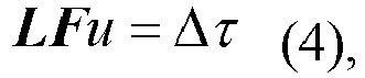
- the fault control beam tomography operator is introduced to a tomography inversion target function for regularization constraint, to obtain a tomography inversion target function into which the regularization constraint has been added.
- a control beam tomography velocity modeling technology directed to a fault can be implemented.
- the tomography inversion target function into which the regularization constraint has been added is solved to obtain a velocity around a fault.
- the method for fault control beam tomography regularization in the present disclosure adopts a strategy of solving by offset iteration, and a fault velocity obtained by solving the tomography inversion target function into which the regularization constraint has been added may be used to acquire a seismic imaging data volume in a next cycle of tomography inversion.
- a high-precision velocity model directed to the fault may be obtained by solving the formula (4), and the velocity modeling precision of both sides of the fault can be improved evidently.
- the step of the solving the tomography inversion target function into which the regularization constraint has been added to obtain the velocity around the fault includes: solving the tomography inversion target function into which the regularization constraint has been added by using a preconditioned conjugate gradient method to obtain the velocity around the fault.
- the present disclosure involves in technology research and develop against a fault velocity modeling difficulty.
- the method adopted includes: guiding and adjusting a ray beam distribution by a coherence attribute, so as to form a control beam tomography regularization operator which is introduced to a target function.
- Effects of the regularization operator mainly lie in the following two aspects: by using the operator to control a ray beam direction for keeping away from an anomalous body, so as to avoid scattering that cannot be simulated and enable an accurate path of ray tracing; and meanwhile, by performing data-driven monitoring on an abnormal ray path, so as to further eliminate a multi-path (error-path) ray beam caused by a velocity abnormity and improve tomography stability and precision.
- the method for fault control beam tomography regularization in the present disclosure is established on the basis of an offset velocity modeling process, and uses a strategy of solving by offset iteration, and each cycle of updating is performed by using a result of a previous cycle as data input.
- a coherence attribute is extracted from a seismic imaging data volume corresponding to a velocity in the previous cycle during the offset velocity modeling, and the data of the coherence attribute is resampled.
- a high-precision velocity model directed to the fault can be obtained by solving the calculation formula (4), and the velocity modeling precision of both sides of the fault can be improved evidently.
- the tomography inversion target function into which the regularization constraint has been added is solved to obtain a velocity around a fault.
- the method for fault control beam tomography regularization in the present disclosure adopts a strategy of solving by offset iteration, and a fault velocity obtained by solving the tomography inversion target function into which the regularization constraint has been added may be used to acquire a seismic imaging data volume in a next cycle of tomography inversion.
- the present disclosure involves technology research and develop against a modeling difficulty of the velocity around a fault.
- the method adopted includes: guiding and adjusting a ray beam distribution by a coherence attribute, so as to form a control beam tomography regularization operator which is introduced to a target function.
- Effects of the regularization operator mainly lie in the following two aspects: by using the operator to control a ray beam direction for keeping away from an anomalous body, so as to avoid scattering that cannot be simulated and enable an accurate path of ray tracing; and meanwhile, by performing data-driven monitoring on an abnormal ray beam path so as to further eliminate a multi-path (error-path) ray beam caused by a velocity abnormity and improve tomography stability and precision.
- Specific steps of the method include as follows: 1) extracting a coherence attribute C ( m,n,l ) from a seismic imaging data volume; 2) resampling the coherence attribute to obtain a resampling coherence attribute C tomo ( m , n , l ), corresponding to a tomography grid; 3) obtaining an input ray density G tomo ( m , n , l ) by ray tracing; 4) constructing a fault control beam tomography operator F by using the resampling coherence attribute and the input ray density obtained from step 2 to step 3, and introducing the fault control beam tomography operator F to a tomography inversion target function for regularization constraint; and 5) solving the target function to obtain a velocity u around a fault, so as to complete the high-precision velocity modeling for the fault.
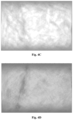
- Fig. 4A shows a coherence attribute obtained by calculating with a seismic imaging data volume in an embodiment. As can be seen from Fig. 4A , the fault is depicted clearly, which may be used for fault guidance.
- Fig. 4B shows a resampling coherence attribute obtained after the resampling is performed. As can be seen from Fig. 4B , by performing the resampling, a signal to noise ratio is improved, and the fault is depicted more clearly, which is more favorable to fault guidance.
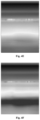
- Fig. 4C shows an input ray density obtained by ray tracing in an embodiment, and the input ray density is used to construct the fault control beam tomography regularization operator.
- the ray density appears disordered on the whole, and there are multiple partial abnormities, which is not beneficial to a high-precision velocity inversion.
- Fig. 4D shows an output ray density obtained by ray beam tracing after the constraint of the fault control beam tomography regularization operator is added.
- the ray density is more uniform, and a shadow of the guidance fault can be seen in the ray density; and meanwhile, the output ray density may also be used as the input ray density for a next cycle of iteration updating.
- Fig. 4E shows a velocity model obtained by using a conventional tomography inversion velocity modeling technology. As can be seen from Fig. 4E , a large-scale construction is depicted, but a velocity difference between both sides of the fault is not shown.
- Fig. 4F shows a velocity model obtained by performing a tomography inversion after the fault control beam tomography regularization operator is added. As can be seen from Fig. 4F , after the fault control beam tomography regularization operator is added, a velocity response at both sides of the fault can be evidently shown in the velocity model, and the precision of the velocity model is improved evidently
- Fig. 4G shows an imaging data volume corresponding to the conventional tomography inversion velocity model in Fig. 4E .
- the precision of fault imaging is low, and interior details are depicted poorly.
- Fig. 4H shows an imaging data volume corresponding to the velocity model obtained by performing the tomography inversion after the fault control beam tomography regularization operator is added.
- the precision of main fault imaging is evidently improved, with more clear-cut fault points, clearer fault surfaces, and richer interior details.
- steps in the flowchart of Fig. 1 are shown sequentially with arrows, these steps are not necessarily performed sequentially according to an order shown by the arrows. Unless clearly indicated herein, these steps are not limited in a strict order and may be performed in other orders.
- at least a part of steps in Fig. 1 may include multiple sub-steps or multiple stages, and these sub-steps or stages are not necessarily performed at the same time instant, but may be performed at different time instants; and these sub-steps or stages may not necessarily be performed successively, but may be performed in turn or alternatively with at least a part of other steps or at least a part of sub-steps or stages of other steps.
- an apparatus for fault control beam tomography regularization includes: a seismic imaging data volume acquiring module 210, a coherence attribute extracting module 220, a resampling module 230, a ray density acquiring module 240, a control beam tomography operator calculating module 250, and a regularizing module 260.
- the seismic imaging data volume acquiring module 210 is configured to acquire a seismic imaging data volume.
- the coherence attribute extracting module 220 is configured to extract a coherence attribute from the seismic imaging data volume.
- the resampling module 230 is configured to resample the data of the coherence attribute to obtain a resampling coherence attribute corresponding to a tomography grid.
- the ray density acquiring module 240 is configured to acquire an input ray density.
- the control beam tomography operator calculating module 250 is configured to calculate a fault control beam tomography operator according to the resampling coherence attribute and the input ray density.
- the regularizing module 260 is configured to introduce the fault control beam tomography operator to a tomography inversion target function for regularization constraint, to obtain a tomography inversion target function into which the regularization constraint has been added.
- the seismic imaging data volume acquiring module includes an imaging result acquiring unit and a coherence attribute extracting unit.
- the imaging result acquiring unit is configured to acquire an input seismic imaging data volume.
- the coherence attribute extracting unit is configured to extract the coherence attribute from the input seismic imaging data volume.
- the resampling module is configured to resample the data of the coherence attribute to obtain the resampling coherence attribute corresponding to the tomography grid.
- the ray density acquiring module is configured to acquire an input ray density G tomo ( m , n , l ).
- control beam tomography operator calculating module is configured to calculate a fault control beam tomography operator according to the resampling coherence attribute and the input ray density G tomo ( m , n , l ).
- the apparatus for fault control beam tomography regularization further includes a function solving module configured to solve a tomography inversion target function into which the regularization constraint has been added, to obtain a velocity around the fault.
- the apparatus for fault control beam tomography regularization in the present disclosure adopts a strategy of solving by offset iteration, and a fault velocity obtained by the function solving module may be used to acquire the seismic imaging data volume in a next cycle of tomography inversion.
- the function solving module is further configured to solve the tomography inversion target function into which the regularization constraint has been added by using a preconditioned conjugate gradient method to obtain the velocity around the fault.
- a computer device is provided.
- An internal structure of the computer device is shown in Fig. 3 .
- the computer device includes a processor, a memory, a network interface, a display screen, and an input device which are connected via a system bus.
- the processor of the computer device is used to provide computing and controlling capabilities.
- the memory of the computer device includes a non-volatile storage medium and an internal memory.
- the non-volatile storage medium stores an operating system and a computer program, and the non-volatile storage medium is deployed with a database for seismic data.
- the internal memory provides an environment for running of the operating system and the computer program in the non-volatile storage medium.
- the network interface of the computer device is configured to communicate with other computer devices deployed with application software.
- the computer program is executed by the processor to perform a method for fault control beam tomography regularization.
- the display screen of the computer device may be a liquid crystal display screen or an electronic ink display screen.
- the input device of the computer device may be a touch layer covered on the display screen, may alternatively be a push button, a trackball, or a touchpad disposed on a housing of the computer device, and may alternatively be a keyboard, a touchpad, a mouse and the like connected externally to the computer device.
- Fig. 3 only involves part of the structure related to the solution of the present disclosure, and does not constitute a limitation on the computer device to which the solution of the present disclosure is applied.
- the specific computer device may include more or less components than those shown in Fig. 3 , may combine some components, or may have a different arrangement of components.
- a computer device which includes a memory storing a computer program and a processor.
- the processor when executing the computer program, implements the following steps: acquiring a seismic imaging data volume; extracting a coherence attribute from the seismic imaging data volume; resampling data of the coherence attribute to obtain a resampling coherence attribute corresponding to a tomography grid; obtaining an input ray density by ray tracing; calculating a fault control beam tomography operator according to the resampling coherence attribute and the input ray density; introducing the fault control beam tomography operator to a tomography inversion target function for regularization constraint, to obtain a tomography inversion target function into which the regularization constraint has been added.
- the processor when executing the computer program, further implements the following steps: acquiring the seismic imaging data volume; and extracting the coherence attribute from the seismic imaging data volume.
- the processor when executing the computer program, further implements the following step: calculating a fault control beam tomography operator according to the resampling coherence attribute and the input ray density G tomo ( m , n , l ).
- the processor when executing the computer program, further implements the step of solving a tomography inversion target function into which the regularization constraint has been added, to obtain a velocity around the fault.
- the processor adopts a strategy of solving by offset iteration, and a fault velocity obtained by solving the tomography inversion target function into which the regularization constraint has been added may be used to acquire a seismic imaging data volume in a next cycle of tomography inversion.
- the processor when executing the computer program, further implements the step of solving the tomography inversion target function into which the regularization constraint has been added by using a preconditioned conjugate gradient method to obtain the velocity around the fault.
- a computer readable storage medium on which a computer program is stored.
- the following steps are implemented: acquiring a seismic imaging data volume; extracting a coherence attribute from the seismic imaging data volume; resampling data of the coherence attribute to obtain a resampling coherence attribute corresponding to a tomography grid; obtaining an input ray density by ray tracing; calculating a fault control beam tomography operator according to the resampling coherence attribute and the ray density; introducing the fault control beam tomography operator to a tomography inversion target function for regularization constraint, to obtain a tomography inversion target function into which the regularization constraint has been added.
- the following step is further implemented: acquiring the seismic imaging data volume; and extracting the coherence attribute from the seismic imaging data volume.
- the following step is further implemented: calculating the fault control beam tomography operator according to the resampling coherence attribute and the ray density G tomo ( m , n , l ).
- the following step is further implemented: solving the tomography inversion target function into which the regularization constraint has been added, to obtain a velocity around the fault.
- the processor adopts a strategy of solving by offset iteration, and a fault velocity obtained by solving the tomography inversion target function into which the regularization constraint has been added may be used to acquire the seismic imaging data volume in a next cycle of tomography inversion.
- the following step is further implemented: solving the tomography inversion target function into which the regularization constraint has been added by using a preconditioned conjugate gradient method to obtain the velocity around the fault.
- the fault control beam tomography operator is used to control a ray beam direction for keeping away from an anomalous body, so as to avoid scattering that cannot be simulated, a path of ray tracing can be ensured to be accurate; and meanwhile by performing data-driven monitoring on an abnormal ray beam path so as to further eliminate a multi-path (error-path) ray beam caused by a velocity abnormity, tomography stability and precision can be improved.
- the computer program may be stored in a non-volatile computer readable storage medium, and when the computer program is executed, the process of the above method embodiments may be included.
- Any memory, storage, database, or other medium referred in respective embodiments provided in the present disclosure may include a non-volatile memory and/or a volatile memory.
- the non-volatile memory may include a read-only memory (ROM), a programmable read-only memory (PROM), an electrically programmable read-only-memory (EPROM), or a flash memory.
- the volatile memory may include a random access memory (RAM) or an external cache memory.
- the RAM may be available in various forms, such as a static random access memory (SRAM), a dynamic random access memory (DRAM), a synchronous dynamic random access memory (SDRAM), double data rate synchronous dynamic random access memory (DDRSDRAM), enhanced synchronous dynamic random access memory (ESDRAM), synchronization link dynamic random access memory (SLDRAM), rambus dynamic random access memory (RDRAM), direct rambus dynamic random access memory (DRDRAM), and rambus dynamic random access memory (RDRAM) and the like.
- SRAM static random access memory
- DRAM dynamic random access memory
- SDRAM synchronous dynamic random access memory
- DDRSDRAM double data rate synchronous dynamic random access memory
- ESDRAM enhanced synchronous dynamic random access memory
- SLDRAM synchronization link dynamic random access memory
- RDRAM direct rambus dynamic random access memory
- RDRAM rambus dynamic random access memory
Landscapes
- Engineering & Computer Science (AREA)
- Physics & Mathematics (AREA)
- General Physics & Mathematics (AREA)
- Life Sciences & Earth Sciences (AREA)
- Remote Sensing (AREA)
- Theoretical Computer Science (AREA)
- Geophysics (AREA)
- Acoustics & Sound (AREA)
- Environmental & Geological Engineering (AREA)
- Geology (AREA)
- General Life Sciences & Earth Sciences (AREA)
- Health & Medical Sciences (AREA)
- Data Mining & Analysis (AREA)
- Mathematical Physics (AREA)
- General Health & Medical Sciences (AREA)
- General Engineering & Computer Science (AREA)
- Mathematical Optimization (AREA)
- Mathematical Analysis (AREA)
- Pure & Applied Mathematics (AREA)
- Public Health (AREA)
- Evolutionary Computation (AREA)
- Epidemiology (AREA)
- Medical Informatics (AREA)
- Primary Health Care (AREA)
- Nuclear Medicine, Radiotherapy & Molecular Imaging (AREA)
- Computational Mathematics (AREA)
- Software Systems (AREA)
- Computer Vision & Pattern Recognition (AREA)
- Multimedia (AREA)
- Algebra (AREA)
- Surgery (AREA)
- Evolutionary Biology (AREA)
- Molecular Biology (AREA)
- Computing Systems (AREA)
- Artificial Intelligence (AREA)
- Urology & Nephrology (AREA)
- Bioinformatics & Cheminformatics (AREA)
- Bioinformatics & Computational Biology (AREA)
- Biomedical Technology (AREA)
- Geometry (AREA)
Abstract
Description
- This application claims the priority of Chinese patent application
CN202111248097.4, filed on October 26, 2021 - The present disclosure relates to the technical field of geophysical exploration, and in particular, to a method and apparatus for fault control beam tomography regularization, a computer device, and a storage medium.
- At present, the tomography inversion technology has been widely used in the velocity building in depth domain. The tomography inversion technology is ray-based algorithm, and involves subdividing a velocity model into a plurality of regular grids by grid generation and performing inversion on the velocity in each grid by using a ray tracing technology. Low wavenumber components of the velocity may be obtained by the tomography inversion, with adequate inversion precision for depicting a large-scale construction. With the gradual deepening of the exploration, the gradual increasing of exploration the depth and the gradual minification of the exploration target, tectonic characteristics of underground faults have become an important seismic exploration target. Conventional ray tomography no longer meets precision requirements for tectonic characteristics of the faults, and how to achieve high-precision velocity depiction of both sides of a fault is of great importance to high-precision imaging.
- Based on this, with respect to the above technical problem, it is necessary to provide a method for fault control beam tomography regularization, an apparatus for fault control beam tomography regularization, a computer device, and a storage medium.
- In one aspect, an embodiment of the present disclosure provides a method for fault control beam tomography regularization. The method includes: acquiring a seismic imaging data volume; extracting a coherence attribute from the seismic imaging data volume; resampling data of the coherence attribute to obtain a resampling coherence attribute corresponding to a tomography grid; obtaining an input ray density; calculating a fault control beam tomography operator according to the resampling coherence attribute and the input ray density; and introducing the fault control beam tomography operator to a tomography inversion target function for regularization constraint, to obtain a tomography inversion target function on which the regularization constraint has been performed.
- In another aspect, an embodiment of the present disclosure provides an apparatus for fault control beam tomography regularization. The apparatus includes: a seismic imaging data volume acquiring module configured to acquire a seismic imaging data volume; a coherence attribute extracting module configured to extract a coherence attribute from the seismic imaging data volume; a resampling module configured to resample data of the coherence attribute to obtain a resampling coherence attribute corresponding to a tomography grid; a ray density acquiring module configured to acquire an input ray density; a control beam tomography operator calculating module configured to calculate a fault control beam tomography operator according to the resampling coherence attribute and the input ray density; and a regularizing module configured to introduce the fault control beam tomography operator to a tomography inversion target function for regularization constraint, to obtain a tomography inversion target function on which the regularization constraint has been performed.
- In still another aspect, an embodiment of the present disclosure provides a computer device including a memory on which a computer program is stored and a processor, and the processor, when executing the computer program, implements the above method for fault control beam tomography regularization.
- In further another aspect, an embodiment of the present disclosure provides a computer readable storage medium, on which a computer program is stored, and the above method for fault control beam tomography regularization is implemented when the computer program is executed by the processor.
-
-
Fig. 1 is a schematic flowchart of a method for fault control beam tomography regularization in an embodiment of the present disclosure; -
Fig. 2 is a block diagram of a structure of an apparatus for fault control beam tomography regularization in an embodiment of the present disclosure; -
Fig. 3 is a diagram of an internal structure of a computer device in an embodiment of the present disclosure; -
Fig. 4A is a schematic diagram of a coherence attribute obtained by calculating with a seismic imaging data volume in an embodiment of the present disclosure; -
Fig. 4B is a schematic diagram of a resampling coherence attribute obtained after resampling is performed in an embodiment of the present disclosure; -
Fig. 4C is a schematic diagram of an input ray density obtained by ray tracing in an embodiment of the present disclosure; -
Fig. 4D is a schematic diagram of an output ray density obtained by ray tracing after constraint of a fault control beam tomography regularization operator is added in an embodiment of the present disclosure; -
Fig. 4E is a schematic diagram of a velocity model obtained by a conventional tomography inversion in an embodiment of the present disclosure; -
Fig. 4F is a schematic diagram of a velocity model obtained by performing a tomography inversion after a fault control beam tomography regularization operator is added in an embodiment of the present disclosure; -
Fig. 4G is a schematic diagram of an imaging result corresponding to a conventional tomography inversion velocity model in an embodiment of the present disclosure; and -
Fig. 4H is a schematic diagram of an imaging result corresponding to a velocity model on which a tomography inversion is performed after a fault control beam tomography regularization operator is added in an embodiment of the present disclosure. - In order to make objectives, technical solutions and advantages of the present disclosure clearer, the present disclosure is further described below in detail with reference to accompanying drawings in conjunction with embodiments. It should be understood that, specific embodiments described herein are only for explaining the present disclosure, rather than limiting the present disclosure.
- In the present embodiment, as shown in
Fig. 1 , a method for fault control beam tomography regularization is provided, and the method includes thefollowing steps 110 to 160. - At
step 110, a seismic imaging data volume is acquired. - At
step 120, a coherence attribute is extracted from the seismic imaging data volume. - In an embodiment, the step of the extracting the coherence attribute from the seismic imaging data volume includes: extracting a coherence attribute C(m,n,l) from the seismic imaging data volume.
- At
step 130, data of the coherence attribute is resampled to obtain a resampling coherence attribute corresponding to a tomography grid. - In an embodiment, in the step of the resampling the coherence attribute to obtain the resampling coherence attribute corresponding to the tomography grid, a calculation formula for resampling is represented as:

m ,n ,l ) indicates a coherence attribute at a location point (m ,n ,l ) after the resampling is performed in a tomography grid size; C(m,n,l) indicates a coherence attribute at the location point (m,n,l) obtained by calculating directly with the seismic imaging data volume; and C(m,n,l) may be obtained by calculating with a coherence attribute formula, and resample[•] indicates a resampling operator. - In the present embodiment, a resampling calculation is performed with an average resampling operator. For example, if the resampling is performed in three dimensions at (m,n,l) with an interval of 1 to form a tomography grid (
m ,n ,l ), the calculation formula for the resampling may be expressed as:
m =floor(m / 2),n =floor(n / 2),l =floor(l / 2), floor[•] is a rounding operator, and a denominator in the above formula is 7, which indicates the resampling for 7 points. - At
step 140, an input ray density is obtained by ray tracing. - In the present embodiment, after the resampling coherence attribute is obtained, it is required to obtain an input ray density Gtomo (
m ,n ,l ) by ray tracing. - At
step 150, a fault control beam tomography operator is calculated according to the resampling coherence attribute and the input ray density. - In an embodiment, the step of the calculating the fault control beam tomography operator according to the resampling coherence attribute and the input ray density includes: calculating the fault control beam tomography operator according to the resampling coherence attribute and the input ray density Gtomo (
m ,n ,l ). The fault control beam tomography operator is calculated by using the following calculation formula:
- At
step 160, the fault control beam tomography operator is introduced to a tomography inversion target function for regularization constraint, to obtain a tomography inversion target function into which the regularization constraint has been added. - In the present embodiment, by introducing an operator F to a tomography inversion matrix, a control beam tomography velocity modeling technology directed to a fault can be implemented.
- In an embodiment, in the step of the introducing the fault control beam tomography operator to the tomography inversion target function for regularization constraint, a preconditioned regularization operator is used:

- In an embodiment, after the step of the obtaining the tomography inversion target function into which the regularization constraint has been added, the tomography inversion target function into which the regularization constraint has been added is solved to obtain a velocity around a fault. The method for fault control beam tomography regularization in the present disclosure adopts a strategy of solving by offset iteration, and a fault velocity obtained by solving the tomography inversion target function into which the regularization constraint has been added may be used to acquire a seismic imaging data volume in a next cycle of tomography inversion.
- In the present embodiment, a high-precision velocity model directed to the fault may be obtained by solving the formula (4), and the velocity modeling precision of both sides of the fault can be improved evidently.
- In an embodiment, the step of the solving the tomography inversion target function into which the regularization constraint has been added to obtain the velocity around the fault includes: solving the tomography inversion target function into which the regularization constraint has been added by using a preconditioned conjugate gradient method to obtain the velocity around the fault.
- In the present embodiment, a calculation formula for the preconditioned conjugate gradient method is as follows:

- In the above embodiments, by using the operator to control a ray beam direction for keeping away from an anomalous body so as to avoid scattering that cannot be simulated, a path of ray tracing can be ensured to be accurate; and meanwhile by performing data-driven monitoring on an abnormal ray beam path so as to further eliminate a multi-path (error-path) ray beam caused by a velocity abnormity, tomography stability and precision can be improved.
- The present disclosure involves in technology research and develop against a fault velocity modeling difficulty. The method adopted includes: guiding and adjusting a ray beam distribution by a coherence attribute, so as to form a control beam tomography regularization operator which is introduced to a target function. Effects of the regularization operator mainly lie in the following two aspects: by using the operator to control a ray beam direction for keeping away from an anomalous body, so as to avoid scattering that cannot be simulated and enable an accurate path of ray tracing; and meanwhile, by performing data-driven monitoring on an abnormal ray path, so as to further eliminate a multi-path (error-path) ray beam caused by a velocity abnormity and improve tomography stability and precision.
- The method for fault control beam tomography regularization in the present disclosure is established on the basis of an offset velocity modeling process, and uses a strategy of solving by offset iteration, and each cycle of updating is performed by using a result of a previous cycle as data input. First, a coherence attribute is extracted from a seismic imaging data volume corresponding to a velocity in the previous cycle during the offset velocity modeling, and the data of the coherence attribute is resampled. A specific calculation formula for the resampling is as follows:

m ,n ,l ) indicates a coherence attribute at a location point (m ,n ,l ) after the resampling is performed in a tomography grid size, C(m,n,l) indicates a coherence attribute at the location point (m,n,l) obtained by calculating with the seismic imaging data volume, and resample[•] indicates a resampling operator. The present disclosure involves performing a resampling calculation with an average resampling operator. For example, if the resampling is performed in three dimensions at (m,n,l) with an interval of 1 to form a tomography grid (m ,n ,l ), the above formula may be expressed as:
m -floor(m / 2),n =floor(n / 2),l =floor(l / 2), floor[•] is a rounding operator, and a denominator in the above formula is 7, which indicates resampling for 7 points. After the resampling coherence attribute is obtained, it is required to obtain an input ray density Gtomo (m ,n ,l ) by ray tracing based on a ray tracing result of the previous cycle, and then a fault control beam tomography regularization operator is calculated by using the following formula:


- In an embodiment, after the step of the obtaining the tomography inversion target function into which the regularization constraint has been added, the tomography inversion target function into which the regularization constraint has been added is solved to obtain a velocity around a fault. The method for fault control beam tomography regularization in the present disclosure adopts a strategy of solving by offset iteration, and a fault velocity obtained by solving the tomography inversion target function into which the regularization constraint has been added may be used to acquire a seismic imaging data volume in a next cycle of tomography inversion.
- The present disclosure involves technology research and develop against a modeling difficulty of the velocity around a fault. The method adopted includes: guiding and adjusting a ray beam distribution by a coherence attribute, so as to form a control beam tomography regularization operator which is introduced to a target function. Effects of the regularization operator mainly lie in the following two aspects: by using the operator to control a ray beam direction for keeping away from an anomalous body, so as to avoid scattering that cannot be simulated and enable an accurate path of ray tracing; and meanwhile, by performing data-driven monitoring on an abnormal ray beam path so as to further eliminate a multi-path (error-path) ray beam caused by a velocity abnormity and improve tomography stability and precision. Specific steps of the method include as follows: 1) extracting a coherence attribute C(m,n,l) from a seismic imaging data volume; 2) resampling the coherence attribute to obtain a resampling coherence attribute C tomo(
m ,n ,l ), corresponding to a tomography grid; 3) obtaining an input ray density Gtomo (m ,n ,l ) by ray tracing; 4) constructing a fault control beam tomography operator F by using the resampling coherence attribute and the input ray density obtained from step 2 to step 3, and introducing the fault control beam tomography operator F to a tomography inversion target function for regularization constraint; and 5) solving the target function to obtain a velocity u around a fault, so as to complete the high-precision velocity modeling for the fault. - In order to demonstrate the accuracy and effectiveness of the method and show that the method brings out higher precision, explanations are made by actual data testing.
-
Fig. 4A shows a coherence attribute obtained by calculating with a seismic imaging data volume in an embodiment. As can be seen fromFig. 4A , the fault is depicted clearly, which may be used for fault guidance. -
Fig. 4B shows a resampling coherence attribute obtained after the resampling is performed. As can be seen fromFig. 4B , by performing the resampling, a signal to noise ratio is improved, and the fault is depicted more clearly, which is more favorable to fault guidance. -
Fig. 4C shows an input ray density obtained by ray tracing in an embodiment, and the input ray density is used to construct the fault control beam tomography regularization operator. As can be seen fromFig. 4C , without the constraint of the fault control beam tomography regularization operator, the ray density appears disordered on the whole, and there are multiple partial abnormities, which is not beneficial to a high-precision velocity inversion. -
Fig. 4D shows an output ray density obtained by ray beam tracing after the constraint of the fault control beam tomography regularization operator is added. As can be seen fromFig. 4D , after the fault control beam tomography regularization technology is adopted, compared with the result ofFig. 3 , the ray density is more uniform, and a shadow of the guidance fault can be seen in the ray density; and meanwhile, the output ray density may also be used as the input ray density for a next cycle of iteration updating. -
Fig. 4E shows a velocity model obtained by using a conventional tomography inversion velocity modeling technology. As can be seen fromFig. 4E , a large-scale construction is depicted, but a velocity difference between both sides of the fault is not shown. -
Fig. 4F shows a velocity model obtained by performing a tomography inversion after the fault control beam tomography regularization operator is added. As can be seen fromFig. 4F , after the fault control beam tomography regularization operator is added, a velocity response at both sides of the fault can be evidently shown in the velocity model, and the precision of the velocity model is improved evidently -
Fig. 4G shows an imaging data volume corresponding to the conventional tomography inversion velocity model inFig. 4E . As can be seen fromFig. 4G , the precision of fault imaging is low, and interior details are depicted poorly. -
Fig. 4H shows an imaging data volume corresponding to the velocity model obtained by performing the tomography inversion after the fault control beam tomography regularization operator is added. As can be seen fromFig. 4H , the precision of main fault imaging is evidently improved, with more clear-cut fault points, clearer fault surfaces, and richer interior details. - It should be understood that, although respective steps in the flowchart of
Fig. 1 are shown sequentially with arrows, these steps are not necessarily performed sequentially according to an order shown by the arrows. Unless clearly indicated herein, these steps are not limited in a strict order and may be performed in other orders. In addition, at least a part of steps inFig. 1 may include multiple sub-steps or multiple stages, and these sub-steps or stages are not necessarily performed at the same time instant, but may be performed at different time instants; and these sub-steps or stages may not necessarily be performed successively, but may be performed in turn or alternatively with at least a part of other steps or at least a part of sub-steps or stages of other steps. - In the present embodiment, as shown in
Fig. 2 , an apparatus for fault control beam tomography regularization is provided, and the apparatus includes: a seismic imaging datavolume acquiring module 210, a coherenceattribute extracting module 220, aresampling module 230, a raydensity acquiring module 240, a control beam tomographyoperator calculating module 250, and aregularizing module 260. - The seismic imaging data
volume acquiring module 210 is configured to acquire a seismic imaging data volume. The coherenceattribute extracting module 220 is configured to extract a coherence attribute from the seismic imaging data volume. Theresampling module 230 is configured to resample the data of the coherence attribute to obtain a resampling coherence attribute corresponding to a tomography grid. The raydensity acquiring module 240 is configured to acquire an input ray density. The control beam tomographyoperator calculating module 250 is configured to calculate a fault control beam tomography operator according to the resampling coherence attribute and the input ray density. Theregularizing module 260 is configured to introduce the fault control beam tomography operator to a tomography inversion target function for regularization constraint, to obtain a tomography inversion target function into which the regularization constraint has been added. - In an embodiment, the seismic imaging data volume acquiring module includes an imaging result acquiring unit and a coherence attribute extracting unit. The imaging result acquiring unit is configured to acquire an input seismic imaging data volume. The coherence attribute extracting unit is configured to extract the coherence attribute from the input seismic imaging data volume.
- In an embodiment, the resampling module is configured to resample the data of the coherence attribute to obtain the resampling coherence attribute corresponding to the tomography grid. A calculation formula of the resampling is as follows:

m ,n ,l ) indicates a coherence attribute at a location point (m ,n ,l ) after the resampling is performed in a tomography grid size, C(m,n,l) indicates a coherence attribute at the location point (m,n,l) obtained by calculating directly with an input imaging data volume, and resample[•] indicates a resampling operator. - In an embodiment, the ray density acquiring module is configured to acquire an input ray density Gtomo (
m ,n ,l ). - In an embodiment, the control beam tomography operator calculating module is configured to calculate a fault control beam tomography operator according to the resampling coherence attribute and the input ray density Gtomo (
m ,n ,l ). The fault control beam tomography operator is calculated with the following calculation formula:
- In an embodiment, the regularizing module is configured to introduce the fault control beam tomography operator to the tomography inversion target function for regularization constraint, and a preconditioned regularization operator is used for introducing the fault control beam tomography operator to the tomography inversion target function by a calculation formula:

- In an embodiment, the apparatus for fault control beam tomography regularization further includes a function solving module configured to solve a tomography inversion target function into which the regularization constraint has been added, to obtain a velocity around the fault. The apparatus for fault control beam tomography regularization in the present disclosure adopts a strategy of solving by offset iteration, and a fault velocity obtained by the function solving module may be used to acquire the seismic imaging data volume in a next cycle of tomography inversion.
- In an embodiment, the function solving module is further configured to solve the tomography inversion target function into which the regularization constraint has been added by using a preconditioned conjugate gradient method to obtain the velocity around the fault.
- Specific limitations on the apparatus for fault control beam tomography regularization may be referred to the limitations on the method for fault control beam tomography regularization above, and details thereof are not further described herein. All or part of respective units in the above apparatus for fault control beam tomography regularization may be implemented by software, hardware, or a combination thereof. The above respective units may be implemented in the form of hardware embedded in or independent from the processor of the computer device, and may alternatively be implemented in the form of software stored in the memory of the computer device, so as to facilitate invoking and executing, by the processor, operations corresponding to the above respective units.
- In the present embodiment, a computer device is provided. An internal structure of the computer device is shown in
Fig. 3 . The computer device includes a processor, a memory, a network interface, a display screen, and an input device which are connected via a system bus. The processor of the computer device is used to provide computing and controlling capabilities. The memory of the computer device includes a non-volatile storage medium and an internal memory. The non-volatile storage medium stores an operating system and a computer program, and the non-volatile storage medium is deployed with a database for seismic data. The internal memory provides an environment for running of the operating system and the computer program in the non-volatile storage medium. The network interface of the computer device is configured to communicate with other computer devices deployed with application software. The computer program is executed by the processor to perform a method for fault control beam tomography regularization. The display screen of the computer device may be a liquid crystal display screen or an electronic ink display screen. The input device of the computer device may be a touch layer covered on the display screen, may alternatively be a push button, a trackball, or a touchpad disposed on a housing of the computer device, and may alternatively be a keyboard, a touchpad, a mouse and the like connected externally to the computer device. - Those skilled in the art may understand that, the structure shown in
Fig. 3 only involves part of the structure related to the solution of the present disclosure, and does not constitute a limitation on the computer device to which the solution of the present disclosure is applied. The specific computer device may include more or less components than those shown inFig. 3 , may combine some components, or may have a different arrangement of components. - In an embodiment, a computer device is provided, which includes a memory storing a computer program and a processor. The processor, when executing the computer program, implements the following steps: acquiring a seismic imaging data volume; extracting a coherence attribute from the seismic imaging data volume; resampling data of the coherence attribute to obtain a resampling coherence attribute corresponding to a tomography grid; obtaining an input ray density by ray tracing; calculating a fault control beam tomography operator according to the resampling coherence attribute and the input ray density; introducing the fault control beam tomography operator to a tomography inversion target function for regularization constraint, to obtain a tomography inversion target function into which the regularization constraint has been added.
- In an embodiment, the processor, when executing the computer program, further implements the following steps: acquiring the seismic imaging data volume; and extracting the coherence attribute from the seismic imaging data volume.
- In an embodiment, the processor, when executing the computer program, implements the step of the resampling the data of the coherence attribute to obtain a resampling coherence attribute corresponding to a tomography grid, by a calculation formula of resampling:

m ,n ,l ) indicates a coherence attribute at a location point (m ,n ,l ) after the resampling is performed in a tomography grid size, C(m,n,l) indicates a coherence attribute at the location point (m,n,l) obtained by calculating with the seismic imaging data volume, and resample[•] indicates a resampling operator. - In an embodiment, the processor, when executing the computer program, further implements the following step: calculating a fault control beam tomography operator according to the resampling coherence attribute and the input ray density Gtomo (
m ,n ,l ). The fault control beam tomography operator is calculated with the following calculation formula:
- In an embodiment, the processor, when executing the computer program, implements the step of introducing the fault control beam tomography operator to the tomography inversion target function for regularization constraint, and a preconditioned regularization operator is used to introduce the fault control beam tomography operator to the tomography inversion target function by a calculation formula:

- In an embodiment, the processor, when executing the computer program, further implements the step of solving a tomography inversion target function into which the regularization constraint has been added, to obtain a velocity around the fault. The processor adopts a strategy of solving by offset iteration, and a fault velocity obtained by solving the tomography inversion target function into which the regularization constraint has been added may be used to acquire a seismic imaging data volume in a next cycle of tomography inversion.
- In an embodiment, the processor, when executing the computer program, further implements the step of solving the tomography inversion target function into which the regularization constraint has been added by using a preconditioned conjugate gradient method to obtain the velocity around the fault.
- In the present embodiment, a computer readable storage medium is provided, on which a computer program is stored. When the computer program is executed by a processor, the following steps are implemented: acquiring a seismic imaging data volume; extracting a coherence attribute from the seismic imaging data volume; resampling data of the coherence attribute to obtain a resampling coherence attribute corresponding to a tomography grid; obtaining an input ray density by ray tracing; calculating a fault control beam tomography operator according to the resampling coherence attribute and the ray density; introducing the fault control beam tomography operator to a tomography inversion target function for regularization constraint, to obtain a tomography inversion target function into which the regularization constraint has been added.
- In an embodiment, when the computer program is executed by the processor, the following step is further implemented: acquiring the seismic imaging data volume; and extracting the coherence attribute from the seismic imaging data volume.
- In an embodiment, when the computer program is executed by the processor, the following step is further implemented: resampling the data of the coherence attribute to obtain a resampling coherence attribute corresponding to a tomography grid by a calculation formula of resampling:

m ,n ,l ) indicates a coherence attribute at a location point (m ,n ,l ) after the resampling is performed in a tomography grid size, C(m,n,l) indicates a coherence attribute at the location point (m,n,l) obtained by calculating with the seismic imaging data volume, and resample[•] indicates a resampling operator. - In an embodiment, when the computer program is executed by the processor, the following step is further implemented: calculating the fault control beam tomography operator according to the resampling coherence attribute and the ray density Gtomo (
m ,n ,l ). The fault control beam tomography operator is calculated with the following calculation formula:
- In an embodiment, when the computer program is executed by the processor, the following step is further implemented: introducing the fault control beam tomography operator to the tomography inversion target function for regularization constraint, and a preconditioned regularization operator is uses to introduce the fault control beam tomography operator to the tomography inversion target function by a calculation formula:

- In an embodiment, when the computer program is executed by the processor, the following step is further implemented: solving the tomography inversion target function into which the regularization constraint has been added, to obtain a velocity around the fault. The processor adopts a strategy of solving by offset iteration, and a fault velocity obtained by solving the tomography inversion target function into which the regularization constraint has been added may be used to acquire the seismic imaging data volume in a next cycle of tomography inversion.
- In an embodiment, when the computer program is executed by the processor, the following step is further implemented: solving the tomography inversion target function into which the regularization constraint has been added by using a preconditioned conjugate gradient method to obtain the velocity around the fault.
- By the above method for fault control beam tomography regularization, the apparatus for fault control beam tomography regularization, the computer device, and the storage medium, the fault control beam tomography operator is used to control a ray beam direction for keeping away from an anomalous body, so as to avoid scattering that cannot be simulated, a path of ray tracing can be ensured to be accurate; and meanwhile by performing data-driven monitoring on an abnormal ray beam path so as to further eliminate a multi-path (error-path) ray beam caused by a velocity abnormity, tomography stability and precision can be improved.
- A person of ordinary skills may understand that all or part of the process in the above method embodiments may be completed by using the computer program to instruct relevant hardware. The computer program may be stored in a non-volatile computer readable storage medium, and when the computer program is executed, the process of the above method embodiments may be included. Any memory, storage, database, or other medium referred in respective embodiments provided in the present disclosure may include a non-volatile memory and/or a volatile memory. The non-volatile memory may include a read-only memory (ROM), a programmable read-only memory (PROM), an electrically programmable read-only-memory (EPROM), or a flash memory. The volatile memory may include a random access memory (RAM) or an external cache memory. As illustration rather than limitation, the RAM may be available in various forms, such as a static random access memory (SRAM), a dynamic random access memory (DRAM), a synchronous dynamic random access memory (SDRAM), double data rate synchronous dynamic random access memory (DDRSDRAM), enhanced synchronous dynamic random access memory (ESDRAM), synchronization link dynamic random access memory (SLDRAM), rambus dynamic random access memory (RDRAM), direct rambus dynamic random access memory (DRDRAM), and rambus dynamic random access memory (RDRAM) and the like.
- Respective technical features in the above embodiments may be combined in any manner. For brevity of description, not all possible combinations of respective technical features in the above embodiments are described, but these combinations of features shall all fall into the scope of recitation of the description as long as there is no conflict.
- The above embodiments are only several embodiments of the present embodiments and are described specifically and in detail, but cannot be understood as limitation on the scope of the present disclosure. It should be noted that, for a person of ordinary skills in the art, several variations and improvements can be made without departing the concept of the present disclosure, and these variations and improvements all fall into the protection scope of the present disclosure. Therefore, the protection scope of the present disclosure shall be confined by the appended claims.
Claims (11)
- A method for fault control beam tomography regularization, comprising:acquiring a seismic imaging data volume;extracting a coherence attribute from the seismic imaging data volume;resampling data of the coherence attribute to obtain a resampling coherence attribute corresponding to a tomography grid;obtaining an input ray density;calculating a fault control beam tomography operator according to the resampling coherence attribute and the input ray density; andintroducing the fault control beam tomography operator to a tomography inversion target function for regularization constraint, to obtain a tomography inversion target function into which the regularization constraint has been added.
- The method according to claim 1, wherein in a step of the resampling the data of the coherence attribute to obtain the resampling coherence attribute corresponding to the tomography grid, a calculation formula of the resampling is:

m ,n ,l ), indicates a coherence attribute at a location point (m ,n ,l ) after the resampling is performed in a tomography grid size, C(m ,n ,l ) indicates a coherence attribute at the location point (m,n,l) obtained by calculating with the seismic imaging data volume, and resample[•] indicates a resampling operator. - The method according to claim 2, wherein a step of the calculating the fault control beam tomography operator according to the resampling coherence attribute and the input ray density comprises:calculating the fault control beam tomography operator according to the resampling coherence attribute and the input ray density Gtomo (
m ,n ,l ), wherein the fault control beam tomography operator is calculated with a following calculation formula: wherein F(i,j,k) is a fault control beam tomography operator at a grid location point (i,j,k), Ctomo [i-M 1,j-M 2,k-M 3] indicates a resampling coherence attribute at the grid location point (i,j,k) in a calculation time window (2M 1+1)×(2M 2+1)×(2M 3+1), Gtomo [i-M 1,j-M 2,k-M 3], indicates an inputray density value at the grid location point (i,j,k) in the time window (2M 1+1)×(2M 2+1)×(2M 3+1), and M 1, M 2 and M 3 are half time window lengths of three dimensions, respectively.
 - The method according to claim 1, wherein in a step of the introducing the fault control beam tomography operator to the tomography inversion target function for regularization constraint, a preconditioned regularization operator is used to introduce the fault control beam tomography operator to the tomography inversion target function by a calculation formula:
- The method according to claim 1, wherein after a step of the obtaining the tomography inversion target function into which the regularization constraint has been added, the method further comprises:
solving the tomography inversion target function into which the regularization constraint has been added to obtain a velocity around a fault. - The method according to claim 5, wherein the acquiring the seismic imaging data volume comprises:
acquiring the seismic imaging data volume according to the velocity around the fault. - The method according to claim 5, wherein a step of the solving the tomography inversion target function into which the regularization constraint has been added to obtain the velocity around the fault comprises:
solving the tomography inversion target function into which the regularization constraint has been added by using a preconditioned conjugate gradient method to obtain the velocity around the fault. - The method according to claim 1, wherein the input ray density is obtained by ray tracing.
- A fault control beam tomography regularization apparatus, comprising:a seismic imaging data volume acquiring module configured to acquire a seismic imaging data volume;a coherence attribute extracting module configured to extract a coherence attribute from the seismic imaging data volume;a resampling module configured to resample data of the coherence attribute to obtain a resampling coherence attribute corresponding to a tomography grid;a ray density acquiring module configured to acquire an input ray density;a control beam tomography operator calculating module configured to calculate a fault control beam tomography operator according to the resampling coherence attribute and the input ray density; anda regularizing module configured to introduce the fault control beam tomography operator to a tomography inversion target function for regularization constraint, to obtain a tomography inversion target function into which the regularization constraint has been added.
- A computer device, comprising a memory on which a computer program is stored and a processor, wherein the processor, when executing the computer program, implements steps of the method according to claims 1 to 8.
- A computer readable storage medium, on which a computer program is stored, wherein when the computer program is executed by a processor, steps of the method according to claims 1 to 8 are implemented.
Applications Claiming Priority (2)
| Application Number | Priority Date | Filing Date | Title |
|---|---|---|---|
| CN202111248097.4A CN116029077A (en) | 2021-10-26 | 2021-10-26 | Crack control beam tomography regularization method, device, computer and storage medium |
| PCT/CN2022/127620 WO2023072132A1 (en) | 2021-10-26 | 2022-10-26 | Fracture control beam tomography regularization method and apparatus, computer device, and storage medium |
Publications (2)
| Publication Number | Publication Date |
|---|---|
| EP4425365A1 true EP4425365A1 (en) | 2024-09-04 |
| EP4425365A4 EP4425365A4 (en) | 2025-10-29 |
Family
ID=86090048
Family Applications (1)
| Application Number | Title | Priority Date | Filing Date |
|---|---|---|---|
| EP22886008.6A Pending EP4425365A4 (en) | 2021-10-26 | 2022-10-26 | METHOD AND DEVICE FOR REGULATING A FRACTURE-CONTROLLED BREATHTOGRAPHY, COMPUTER DEVICE AND STORAGE MEDIUM |
Country Status (5)
| Country | Link |
|---|---|
| US (1) | US20240295667A1 (en) |
| EP (1) | EP4425365A4 (en) |
| CN (1) | CN116029077A (en) |
| IL (1) | IL309096A (en) |
| WO (1) | WO2023072132A1 (en) |
Families Citing this family (1)
| Publication number | Priority date | Publication date | Assignee | Title |
|---|---|---|---|---|
| CN121679692A (en) * | 2024-09-14 | 2026-03-17 | 中国石油化工股份有限公司 | Deep boundary-oriented speed modeling illumination compensation method and device |
Family Cites Families (8)
| Publication number | Priority date | Publication date | Assignee | Title |
|---|---|---|---|---|
| US7472046B2 (en) * | 2003-06-27 | 2008-12-30 | Lucasfilm Entertainment Company Ltd. | Apparatus and method of simulating the movement of elements through a region of 3D space |
| US20130258810A1 (en) * | 2012-03-30 | 2013-10-03 | Wenyi Hu | Method and System for Tomographic Inversion |
| CN105022045A (en) * | 2015-07-14 | 2015-11-04 | 华东交通大学 | Multi-source data fusion-based three-dimensional ionosphere chromatographic method |
| WO2018080460A1 (en) * | 2016-10-25 | 2018-05-03 | Landmark Graphics Corporation | Estimating interval anisotropy parameter for pre-stack depth migration using a least-squares method |
| CN106597533B (en) * | 2016-11-17 | 2018-08-03 | 中国石油化工股份有限公司 | A kind of Depth Domain velocity modeling method for mountain front seism processing |
| CN111665543A (en) * | 2019-03-07 | 2020-09-15 | 中普宝信(北京)科技有限公司 | Acoustic parameter acquisition method for subway danger detection |
| CN111208560B (en) * | 2020-01-15 | 2021-04-23 | 中南大学 | Simultaneous prediction method of horizontal fractures and vertical fractures in orthogonal medium fractured reservoirs |
| CN112285771A (en) * | 2020-09-03 | 2021-01-29 | 田晓峰 | Hidden fracture imaging method in urban active fault detection |
-
2021
- 2021-10-26 CN CN202111248097.4A patent/CN116029077A/en active Pending
-
2022
- 2022-10-26 EP EP22886008.6A patent/EP4425365A4/en active Pending
- 2022-10-26 IL IL309096A patent/IL309096A/en unknown
- 2022-10-26 US US18/568,556 patent/US20240295667A1/en active Pending
- 2022-10-26 WO PCT/CN2022/127620 patent/WO2023072132A1/en not_active Ceased
Also Published As
| Publication number | Publication date |
|---|---|
| CN116029077A (en) | 2023-04-28 |
| EP4425365A4 (en) | 2025-10-29 |
| IL309096A (en) | 2024-02-01 |
| WO2023072132A1 (en) | 2023-05-04 |
| US20240295667A1 (en) | 2024-09-05 |
Similar Documents
| Publication | Publication Date | Title |
|---|---|---|
| Curtin et al. | Thermal resummation and phase transitions | |
| Zache et al. | Extracting the field theory description of a quantum many-body system from experimental data | |
| Sevieri et al. | Concrete gravity dams model parameters updating using static measurements | |
| Scherzer et al. | Controlling complex Langevin simulations of lattice models by boundary term analysis | |
| US20220027774A1 (en) | Quantum control pulse generation method, device, and storage medium | |
| Zhang | A semiparametric pseudolikelihood estimation method for panel count data | |
| US20220230088A1 (en) | Method and apparatus for crosstalk analysis of qubits, computer device, and storage medium | |
| Cruz-Fabiano et al. | Assessment of simplified 2D grain growth models from numerical experiments based on a level set framework | |
| Acharya et al. | A diagnostic tool for population models using non-compartmental analysis: the ncappc package for R | |
| De Curtis et al. | Collision integrals for cosmological phase transitions | |
| Steiner et al. | Convergence of Parareal for the Navier-Stokes equations depending on the Reynolds number | |
| CN117726182B (en) | Multi-stage tunnel crossing difficult stratum gushing water disaster risk prediction method and system | |
| Shelton et al. | Probability of collision between space objects including model uncertainty | |
| US9239398B2 (en) | Method of generating and combining multiple horizons to determine a seismic horizon and its uncertainty | |
| Ndanguza et al. | Analysis of bias in an Ebola epidemic model by extended Kalman filter approach | |
| US20240295667A1 (en) | Fault control beam tomography regularization method and apparatus, computer device, and storage medium | |
| Krymskaya et al. | An iterative ensemble Kalman filter for reservoir engineering applications | |
| CN118426042B (en) | A method and device for quickly constructing a precise seismic field | |
| Katsoulakis et al. | Multiscale couplings in prototype hybrid deterministic/stochastic systems: Part I, deterministic closures | |
| CN119045071A (en) | Transient electromagnetic deep learning inversion method, system, equipment and medium | |
| CN108828662A (en) | A kind of earthquake source inverting visual analysis method, storage medium and server | |
| CN115687887A (en) | A sparse time-frequency analysis method, device and readable storage medium based on self-supervised generative adversarial learning and reconstruction of physical constraints | |
| Armegioiu et al. | Rectified flows for fast multiscale fluid flow modeling | |
| Zhang et al. | A dual interpolation boundary face method for 3D elasticity | |
| RU2859362C2 (en) | Method and device for fault ray tomography regularisation, computer device and storage medium |
Legal Events
| Date | Code | Title | Description |
|---|---|---|---|
| STAA | Information on the status of an ep patent application or granted ep patent |
Free format text: STATUS: THE INTERNATIONAL PUBLICATION HAS BEEN MADE |
|
| PUAI | Public reference made under article 153(3) epc to a published international application that has entered the european phase |
Free format text: ORIGINAL CODE: 0009012 |
|
| STAA | Information on the status of an ep patent application or granted ep patent |
Free format text: STATUS: REQUEST FOR EXAMINATION WAS MADE |
|
| 17P | Request for examination filed |
Effective date: 20231207 |
|
| AK | Designated contracting states |
Kind code of ref document: A1 Designated state(s): AL AT BE BG CH CY CZ DE DK EE ES FI FR GB GR HR HU IE IS IT LI LT LU LV MC ME MK MT NL NO PL PT RO RS SE SI SK SM TR |
|
| DAV | Request for validation of the european patent (deleted) | ||
| DAX | Request for extension of the european patent (deleted) | ||
| A4 | Supplementary search report drawn up and despatched |
Effective date: 20250930 |
|
| RIC1 | Information provided on ipc code assigned before grant |
Ipc: G06F 30/20 20200101AFI20250924BHEP Ipc: G06F 17/18 20060101ALI20250924BHEP Ipc: G01V 1/28 20060101ALI20250924BHEP Ipc: G01V 1/30 20060101ALI20250924BHEP Ipc: G06N 3/00 20230101ALI20250924BHEP Ipc: G16H 20/40 20180101ALI20250924BHEP Ipc: G16H 30/40 20180101ALI20250924BHEP Ipc: G01V 1/36 20060101ALI20250924BHEP |