EP4425304A2 - Radar-assisted three-dimensional (3d) detection for near-eye display devices - Google Patents
Radar-assisted three-dimensional (3d) detection for near-eye display devices Download PDFInfo
- Publication number
- EP4425304A2 EP4425304A2 EP24154466.7A EP24154466A EP4425304A2 EP 4425304 A2 EP4425304 A2 EP 4425304A2 EP 24154466 A EP24154466 A EP 24154466A EP 4425304 A2 EP4425304 A2 EP 4425304A2
- Authority
- EP
- European Patent Office
- Prior art keywords
- radar sub
- image
- radar
- display device
- user
- Prior art date
- Legal status (The legal status is an assumption and is not a legal conclusion. Google has not performed a legal analysis and makes no representation as to the accuracy of the status listed.)
- Withdrawn
Links
Images





Classifications
-
- G—PHYSICS
- G01—MEASURING; TESTING
- G01S—RADIO DIRECTION-FINDING; RADIO NAVIGATION; DETERMINING DISTANCE OR VELOCITY BY USE OF RADIO WAVES; LOCATING OR PRESENCE-DETECTING BY USE OF THE REFLECTION OR RERADIATION OF RADIO WAVES; ANALOGOUS ARRANGEMENTS USING OTHER WAVES
- G01S13/00—Systems using the reflection or reradiation of radio waves, e.g. radar systems; Analogous systems using reflection or reradiation of waves whose nature or wavelength is irrelevant or unspecified
- G01S13/86—Combinations of radar systems with non-radar systems, e.g. sonar, direction finder
- G01S13/867—Combination of radar systems with cameras
-
- G—PHYSICS
- G06—COMPUTING OR CALCULATING; COUNTING
- G06F—ELECTRIC DIGITAL DATA PROCESSING
- G06F3/00—Input arrangements for transferring data to be processed into a form capable of being handled by the computer; Output arrangements for transferring data from processing unit to output unit, e.g. interface arrangements
- G06F3/01—Input arrangements or combined input and output arrangements for interaction between user and computer
- G06F3/017—Gesture based interaction, e.g. based on a set of recognized hand gestures
-
- A—HUMAN NECESSITIES
- A61—MEDICAL OR VETERINARY SCIENCE; HYGIENE
- A61B—DIAGNOSIS; SURGERY; IDENTIFICATION
- A61B5/00—Measuring for diagnostic purposes; Identification of persons
- A61B5/02—Detecting, measuring or recording for evaluating the cardiovascular system, e.g. pulse, heart rate, blood pressure or blood flow
- A61B5/0205—Simultaneously evaluating both cardiovascular conditions and different types of body conditions, e.g. heart and respiratory condition
-
- G—PHYSICS
- G01—MEASURING; TESTING
- G01S—RADIO DIRECTION-FINDING; RADIO NAVIGATION; DETERMINING DISTANCE OR VELOCITY BY USE OF RADIO WAVES; LOCATING OR PRESENCE-DETECTING BY USE OF THE REFLECTION OR RERADIATION OF RADIO WAVES; ANALOGOUS ARRANGEMENTS USING OTHER WAVES
- G01S13/00—Systems using the reflection or reradiation of radio waves, e.g. radar systems; Analogous systems using reflection or reradiation of waves whose nature or wavelength is irrelevant or unspecified
- G01S13/02—Systems using reflection of radio waves, e.g. primary radar systems; Analogous systems
- G01S13/50—Systems of measurement based on relative movement of target
-
- G—PHYSICS
- G01—MEASURING; TESTING
- G01S—RADIO DIRECTION-FINDING; RADIO NAVIGATION; DETERMINING DISTANCE OR VELOCITY BY USE OF RADIO WAVES; LOCATING OR PRESENCE-DETECTING BY USE OF THE REFLECTION OR RERADIATION OF RADIO WAVES; ANALOGOUS ARRANGEMENTS USING OTHER WAVES
- G01S13/00—Systems using the reflection or reradiation of radio waves, e.g. radar systems; Analogous systems using reflection or reradiation of waves whose nature or wavelength is irrelevant or unspecified
- G01S13/02—Systems using reflection of radio waves, e.g. primary radar systems; Analogous systems
- G01S13/50—Systems of measurement based on relative movement of target
- G01S13/58—Velocity or trajectory determination systems; Sense-of-movement determination systems
- G01S13/62—Sense-of-movement determination
-
- G—PHYSICS
- G01—MEASURING; TESTING
- G01S—RADIO DIRECTION-FINDING; RADIO NAVIGATION; DETERMINING DISTANCE OR VELOCITY BY USE OF RADIO WAVES; LOCATING OR PRESENCE-DETECTING BY USE OF THE REFLECTION OR RERADIATION OF RADIO WAVES; ANALOGOUS ARRANGEMENTS USING OTHER WAVES
- G01S13/00—Systems using the reflection or reradiation of radio waves, e.g. radar systems; Analogous systems using reflection or reradiation of waves whose nature or wavelength is irrelevant or unspecified
- G01S13/88—Radar or analogous systems specially adapted for specific applications
-
- G—PHYSICS
- G01—MEASURING; TESTING
- G01S—RADIO DIRECTION-FINDING; RADIO NAVIGATION; DETERMINING DISTANCE OR VELOCITY BY USE OF RADIO WAVES; LOCATING OR PRESENCE-DETECTING BY USE OF THE REFLECTION OR RERADIATION OF RADIO WAVES; ANALOGOUS ARRANGEMENTS USING OTHER WAVES
- G01S13/00—Systems using the reflection or reradiation of radio waves, e.g. radar systems; Analogous systems using reflection or reradiation of waves whose nature or wavelength is irrelevant or unspecified
- G01S13/88—Radar or analogous systems specially adapted for specific applications
- G01S13/89—Radar or analogous systems specially adapted for specific applications for mapping or imaging
-
- G—PHYSICS
- G01—MEASURING; TESTING
- G01S—RADIO DIRECTION-FINDING; RADIO NAVIGATION; DETERMINING DISTANCE OR VELOCITY BY USE OF RADIO WAVES; LOCATING OR PRESENCE-DETECTING BY USE OF THE REFLECTION OR RERADIATION OF RADIO WAVES; ANALOGOUS ARRANGEMENTS USING OTHER WAVES
- G01S7/00—Details of systems according to groups G01S13/00, G01S15/00, G01S17/00
- G01S7/02—Details of systems according to groups G01S13/00, G01S15/00, G01S17/00 of systems according to group G01S13/00
- G01S7/04—Display arrangements
- G01S7/06—Cathode-ray tube displays or other two dimensional or three-dimensional displays
- G01S7/20—Stereoscopic displays; Three-dimensional [3D] displays; Pseudo-3D displays
-
- G—PHYSICS
- G01—MEASURING; TESTING
- G01S—RADIO DIRECTION-FINDING; RADIO NAVIGATION; DETERMINING DISTANCE OR VELOCITY BY USE OF RADIO WAVES; LOCATING OR PRESENCE-DETECTING BY USE OF THE REFLECTION OR RERADIATION OF RADIO WAVES; ANALOGOUS ARRANGEMENTS USING OTHER WAVES
- G01S7/00—Details of systems according to groups G01S13/00, G01S15/00, G01S17/00
- G01S7/02—Details of systems according to groups G01S13/00, G01S15/00, G01S17/00 of systems according to group G01S13/00
- G01S7/41—Details of systems according to groups G01S13/00, G01S15/00, G01S17/00 of systems according to group G01S13/00 using analysis of echo signal for target characterisation; Target signature; Target cross-section
- G01S7/415—Identification of targets based on measurements of movement associated with the target
-
- G—PHYSICS
- G02—OPTICS
- G02B—OPTICAL ELEMENTS, SYSTEMS OR APPARATUS
- G02B27/00—Optical systems or apparatus not provided for by any of the groups G02B1/00 - G02B26/00, G02B30/00
- G02B27/01—Head-up displays
- G02B27/017—Head mounted
-
- G—PHYSICS
- G06—COMPUTING OR CALCULATING; COUNTING
- G06F—ELECTRIC DIGITAL DATA PROCESSING
- G06F3/00—Input arrangements for transferring data to be processed into a form capable of being handled by the computer; Output arrangements for transferring data from processing unit to output unit, e.g. interface arrangements
- G06F3/01—Input arrangements or combined input and output arrangements for interaction between user and computer
- G06F3/011—Arrangements for interaction with the human body, e.g. for user immersion in virtual reality
-
- G—PHYSICS
- G06—COMPUTING OR CALCULATING; COUNTING
- G06F—ELECTRIC DIGITAL DATA PROCESSING
- G06F3/00—Input arrangements for transferring data to be processed into a form capable of being handled by the computer; Output arrangements for transferring data from processing unit to output unit, e.g. interface arrangements
- G06F3/01—Input arrangements or combined input and output arrangements for interaction between user and computer
- G06F3/011—Arrangements for interaction with the human body, e.g. for user immersion in virtual reality
- G06F3/012—Head tracking input arrangements
-
- G—PHYSICS
- G06—COMPUTING OR CALCULATING; COUNTING
- G06F—ELECTRIC DIGITAL DATA PROCESSING
- G06F3/00—Input arrangements for transferring data to be processed into a form capable of being handled by the computer; Output arrangements for transferring data from processing unit to output unit, e.g. interface arrangements
- G06F3/01—Input arrangements or combined input and output arrangements for interaction between user and computer
- G06F3/011—Arrangements for interaction with the human body, e.g. for user immersion in virtual reality
- G06F3/013—Eye tracking input arrangements
-
- G—PHYSICS
- G06—COMPUTING OR CALCULATING; COUNTING
- G06F—ELECTRIC DIGITAL DATA PROCESSING
- G06F3/00—Input arrangements for transferring data to be processed into a form capable of being handled by the computer; Output arrangements for transferring data from processing unit to output unit, e.g. interface arrangements
- G06F3/01—Input arrangements or combined input and output arrangements for interaction between user and computer
- G06F3/011—Arrangements for interaction with the human body, e.g. for user immersion in virtual reality
- G06F3/015—Input arrangements based on nervous system activity detection, e.g. brain waves [EEG] detection, electromyograms [EMG] detection, electrodermal response detection
-
- G—PHYSICS
- G02—OPTICS
- G02B—OPTICAL ELEMENTS, SYSTEMS OR APPARATUS
- G02B27/00—Optical systems or apparatus not provided for by any of the groups G02B1/00 - G02B26/00, G02B30/00
- G02B27/01—Head-up displays
- G02B27/0101—Head-up displays characterised by optical features
- G02B2027/0138—Head-up displays characterised by optical features comprising image capture systems, e.g. camera
-
- G—PHYSICS
- G02—OPTICS
- G02B—OPTICAL ELEMENTS, SYSTEMS OR APPARATUS
- G02B27/00—Optical systems or apparatus not provided for by any of the groups G02B1/00 - G02B26/00, G02B30/00
- G02B27/01—Head-up displays
- G02B27/017—Head mounted
- G02B2027/0178—Eyeglass type
Definitions
- This patent application relates generally to near-eye display devices, and in particular, gesture and three-dimensional (3D) scene capture and detection through a radar and/or a camera on a near-eye display device.
- VR virtual reality
- AR augmented reality
- MR mixed reality
- Metadata content within and associated with a real and/or virtual environment
- HMD head-mounted display
- the head-mounted display (HMD) device may project or direct light to may display virtual objects or combine images of real objects with virtual objects, as in virtual reality (VR), augmented reality (AR), or mixed reality (MR) applications.
- VR virtual reality
- AR augmented reality
- MR mixed reality
- a user may view both images of virtual objects (e.g., computer-generated images (CGIs)) and the surrounding environment.
- Head-mounted display (HMD) devices may also present interactive content, where a user's (wearer's) gaze may be used as input for the interactive content.
- CGIs computer-generated images
- a detection system for a near-eye display device comprising:
- the gesture may comprise at least one of a hand gesture, a finger gesture, or a body gesture.
- the radar sub-system may be configured to detect the gesture directly or indirectly from a nearby reflective surface.
- An antenna of the radar sub-system may be positioned downward from a head of a user and at a predefined angle to detect the gesture while the user is in a natural pose.
- the image sensor may comprise an outward-facing camera configured to capture the 2D image of the gesture directly or indirectly from a nearby reflective surface.
- the processor may be further configured to: compare an output of the radar sub-system and an output of the image sensor so as to enhance an accuracy of the detected gesture.
- the radar sub-system may be a millimeter-wave radar sub-system.
- a detection system for a near-eye display device comprising:
- the depth characteristic may comprise depth information associated with at least one object in the scene.
- the radar sub-system may comprise a millimeter-wave radar sub-system that provides millimeter level spatial resolution.
- the radar sub-system may employ 58.0 GHz to 63.5 GHz frequency range with a bandwidth of 5.5 GHz.
- the processor may be further configured to provide the reconstructed 3D image of the scene to a display of the near-eye display device.
- a detection system for a near-eye display device comprising:
- the bio-signal may comprise at least one of a breath rate, a heart rate, a twitch or a tremor.
- the detection system may further comprise: an image sensor configured to capture an image, wherein the processor is further configured to:
- the image sensor may comprise an outward-facing camera configured to capture the image directly or indirectly from a nearby reflective surface.
- the captured image may comprise a scene around the user or an image of the user.
- An antenna of the radar sub-system may be positioned downward from a head of the user and at a predefined angle to detect the bio-signal while the user is in a natural pose.
- An antenna of the radar sub-system may be positioned to detect the bio-signal indirectly from a nearby reflective surface.
- the radar sub-system may comprise a millimeter-wave radar sub-system.
- radar refers to an electromagnetic sensor for detecting, locating, tracking, and recognizing objects of various kinds at a distance by transmitting electromagnetic energy toward the objects and observing the echoes returned from the objects.
- a "real scene” refers to a physical environment around a user wearing augmented reality (AR) / virtual reality (VR) display device such as a near-eye display device.
- AR augmented reality
- VR virtual reality
- a “virtual scene” refers to a computer generated image of a scene and/or objects that is displayed through the near-eye display device to the user.
- a “bio-signal” refers to any biometric characteristic of a person that may be detected through a radar, a camera, or other device. Examples of bio-signals include, but are not limited to, hear rate, breath rate, skin movements, muscle contractions, head shaking, hand or finger tremors, and similar ones.
- Augmented reality (AR) / virtual reality (VR) near-eye display devices also referred to as smart glasses, commonly employ capacitive touch technology as a primary user input.
- a user needs to raise and hold their hand to the glass temple arm and swipe fingers in close contact with the smart glass. Supported gestures using this technique are limited, and the posture may be deemed unnatural for some users.
- some smart glasses may be paired with a wrist input device employing tactile input or electromyography technology, such accessory devices may not be available to all the users.
- a wearable device such as an augmented reality (AR) / virtual reality (VR) near-eye display device may employ radar technology to detect gestures or obtain depth information associated with a real scene around the user.
- An on-board radar sub-system may use time difference, frequency shift, etc. to detect motion such as hand or finger gestures, which may be used as input related to different functions of the near-eye display device. Due to low power consumption, the radar sub-system may be maintained in active mode for longer periods and also be used to activate an on-board camera. In some cases, the radar sub-system may obtain depth information associated with the real scene around the user, and a two-dimensional (2D) image of the real scene may be captured by the on-board camera.
- 2D two-dimensional
- the radar sub-system and camera outputs may then be combined to reconstruct a three-dimensional (3D) image of the real scene.
- bio-signal(s) of the user such as breath rate, heart rate, tremors, twitching, etc. may also be captured by the radar sub-system alone or in combination with the camera and be used for health monitoring.
- Figure 1 illustrates a block diagram of an artificial reality system environment 100 including a near-eye display device, according to an example.
- a “near-eye display device” may refer to a device (e.g., an optical device) that may be in close proximity to a user's eye.
- artificial reality may refer to aspects of, among other things, a "metaverse” or an environment of real and virtual elements and may include use of technologies associated with virtual reality (VR), augmented reality (AR), and/or mixed reality (MR).
- a "user” may refer to a user or wearer of a "near-eye display device.”
- the artificial reality system environment 100 may include a near-eye display device 120, an optional external imaging device 150, and an optional input/output interface 140, each of which may be coupled to a console 110.
- the console 110 may be optional in some instances as the functions of the console 110 may be integrated into the near-eye display device 120.
- the near-eye display device 120 may be a head-mounted display (HMD) that presents content to a user.
- HMD head-mounted display
- an eye box may be desirable to expand an eye box, reduce display haze, improve image quality (e.g., resolution and contrast), reduce physical size, increase power efficiency, and increase or expand field of view (FOV).
- field of view may refer to an angular range of an image as seen by a user, which is typically measured in degrees as observed by one eye (for a monocular head-mounted display (HMD)) or both eyes (for binocular head-mounted displays (HMDs)).
- an "eye box” may be a two-dimensional box that may be positioned in front of the user's eye from which a displayed image from an image source may be viewed.
- a waveguide display e.g., a transparent substrate
- light of projected images may be coupled into a transparent substrate of a waveguide, propagate within the waveguide, and be coupled or directed out of the waveguide at one or more locations to replicate exit pupils and expand the eye box.
- the near-eye display device 120 may include one or more rigid bodies, which may be rigidly or non-rigidly coupled to each other.
- a rigid coupling between rigid bodies may cause the coupled rigid bodies to act as a single rigid entity, while in other examples, a non-rigid coupling between rigid bodies may allow the rigid bodies to move relative to each other.
- the near-eye display device 120 may be implemented in any suitable form-factor, including a head-mounted display (HMD), a pair of glasses, or other similar wearable eyewear or device. Examples of the near-eye display device 120 are further described below with respect to Figures 2 and 3 . Additionally, in some examples, the functionality described herein may be used in a head-mounted display (HMD) or headset that may combine images of an environment external to the near-eye display device 120 and artificial reality content (e.g., computer-generated images).
- HMD head-mounted display
- headset may combine images of an environment external to the near-eye display device 120 and artificial reality content (e.g., computer-generated images).
- the near-eye display device 120 may augment images of a physical, real-world environment external to the near-eye display device 120 with generated and/or overlaid digital content (e.g., images, video, sound, etc.) to present an augmented reality to a user.
- generated and/or overlaid digital content e.g., images, video, sound, etc.
- the near-eye display device 120 may include any number of display electronics 122, display optics 124, and an eye tracking unit 130. In some examples, the near-eye display device 120 may also include one or more locators 126, one or more position sensors 128, an inertial measurement unit (IMU) 132, and a radar subs-system 134. In some examples, the near-eye display device 120 may omit any of the eye tracking unit 130, the one or more locators 126, the one or more position sensors 128, and the inertial measurement unit (IMU) 132, or may include additional elements.
- IMU inertial measurement unit
- the display electronics 122 may display or facilitate the display of images to the user according to data received from, for example, the optional console 110.
- the display electronics 122 may include one or more display panels.
- the display electronics 122 may include any number of pixels to emit light of a predominant color such as red, green, blue, white, or yellow.
- the display electronics 122 may display a three-dimensional (3D) image, e.g., using stereoscopic effects produced by two-dimensional panels, to create a subjective perception of image depth.
- the near-eye display device 120 may include a projector (not shown), which may form an image in angular domain for direct observation by a viewer's eye through a pupil.
- the projector may employ a controllable light source (e.g., a laser source) and a micro-electromechanical system (MEMS) beam scanner to create a light field from, for example, a collimated light beam.
- MEMS micro-electromechanical system
- the same projector or a different projector may be used to project a fringe pattern on the eye, which may be captured by a camera and analyzed (e.g., by the eye tracking unit 130) to determine a position of the eye (the pupil), a gaze, etc.
- the display optics 124 may display image content optically (e.g., using optical waveguides and/or couplers) or magnify image light received from the display electronics 122, correct optical errors associated with the image light, and/or present the corrected image light to a user of the near-eye display device 120.
- the display optics 124 may include a single optical element or any number of combinations of various optical elements as well as mechanical couplings to maintain relative spacing and orientation of the optical elements in the combination.
- one or more optical elements in the display optics 124 may have an optical coating, such as an anti-reflective coating, a reflective coating, a filtering coating, and/or a combination of different optical coatings.
- the display optics 124 may also be designed to correct one or more types of optical errors, such as two-dimensional optical errors, three-dimensional optical errors, or any combination thereof.
- optical errors such as two-dimensional optical errors, three-dimensional optical errors, or any combination thereof.
- two-dimensional errors may include barrel distortion, pincushion distortion, longitudinal chromatic aberration, and/or transverse chromatic aberration.
- three-dimensional errors may include spherical aberration, chromatic aberration field curvature, and astigmatism.
- the one or more locators 126 may be objects located in specific positions relative to one another and relative to a reference point on the near-eye display device 120.
- the optional console 110 may identify the one or more locators 126 in images captured by the optional external imaging device 150 to determine the artificial reality headset's position, orientation, or both.
- the one or more locators 126 may each be a light-emitting diode (LED), a corner cube reflector, a reflective marker, a type of light source that contrasts with an environment in which the near-eye display device 120 operates, or any combination thereof.
- LED light-emitting diode
- corner cube reflector a corner cube reflector
- a reflective marker a type of light source that contrasts with an environment in which the near-eye display device 120 operates, or any combination thereof.
- the external imaging device 150 may include one or more cameras, one or more video cameras, any other device capable of capturing images including the one or more locators 126, or any combination thereof.
- the optional external imaging device 150 may be configured to detect light emitted or reflected from the one or more locators 126 in a field of view of the optional external imaging device 150.
- the one or more position sensors 128 may generate one or more measurement signals in response to motion of the near-eye display device 120.
- Examples of the one or more position sensors 128 may include any number of accelerometers, gyroscopes, magnetometers, and/or other motion-detecting or error-correcting sensors, or any combination thereof.
- the inertial measurement unit (IMU) 132 may be an electronic device that generates fast calibration data based on measurement signals received from the one or more position sensors 128.
- the one or more position sensors 128 may be located external to the inertial measurement unit (IMU) 132, internal to the inertial measurement unit (IMU) 132, or any combination thereof.
- the inertial measurement unit (IMU) 132 may generate fast calibration data indicating an estimated position of the near-eye display device 120 that may be relative to an initial position of the near-eye display device 120.
- the inertial measurement unit (IMU) 132 may integrate measurement signals received from accelerometers over time to estimate a velocity vector and integrate the velocity vector over time to determine an estimated position of a reference point on the near-eye display device 120.
- the inertial measurement unit (IMU) 132 may provide the sampled measurement signals to the optional console 110, which may determine the fast calibration data.
- the eye tracking unit 130 may include one or more eye tracking systems.
- eye tracking may refer to determining an eye's position or relative position, including orientation, location, and/or gaze of a user's eye.
- an eye tracking system may include an imaging system that captures one or more images of an eye and may optionally include a light emitter, which may generate light (e.g., a fringe pattern) that is directed to an eye such that light reflected by the eye may be captured by the imaging system (e.g., a camera).
- the eye tracking unit 130 may capture reflected radio waves emitted by a miniature radar unit. These data associated with the eye may be used to determine or predict eye position, orientation, movement, location, and/or gaze.
- the radar sub-system 134 may be a radar-on-a-chip, a radar transceiver, receive/transmit antenna(s), RF front end circuitry, RF processing circuitry, filters, and/or digital signal processing circuitry integrated on a single ship.
- the radar sub-system may operate at 60 GHz range (e.g., 58.0 to 63.5 GHz with a bandwidth of 5.5 GHz).
- Such a radar sub-system may provide millimeter level spatial resolution (with signal processing enhancements) at low power consumption levels compared to a camera on the near-eye display device 120.
- the radar sub-system 134 may be used standalone to detect hand or finger gestures, in combination with a camera to activate the camera upon detecting motion or for enhanced gesture detection, and to obtain 3D information, which may be combined with 2D image information from the camera to reconstruct 3D scenes.
- the input/output interface 140 may be a device that allows a user to send action requests to the optional console 110.
- an "action request" may be a request to perform a particular action.
- an action request may be to start or to end an application or to perform a particular action within the application.
- the input/output interface 140 may include one or more input devices.
- Example input devices may include a keyboard, a mouse, a game controller, a glove, a button, a touch screen, or any other suitable device for receiving action requests and communicating the received action requests to the optional console 110.
- an action request received by the input/output interface 140 may be communicated to the optional console 110, which may perform an action corresponding to the requested action.
- the optional console 110 may provide content to the near-eye display device 120 for presentation to the user in accordance with information received from one or more of external imaging device 150, the near-eye display device 120, and the input/output interface 140.
- the optional console 110 may include an application store 112, a headset tracking module 114, a virtual reality engine 116, and an eye tracking module 118.
- Some examples of the optional console 110 may include different or additional modules than those described in conjunction with Figure 1 . Functions further described below may be distributed among components of the optional console 110 in a different manner than is described here.
- the optional console 110 may include a processor and a non-transitory computer-readable storage medium storing instructions executable by the processor.
- the processor may include multiple processing units executing instructions in parallel.
- the non-transitory computer-readable storage medium may be any memory, such as a hard disk drive, a removable memory, or a solid-state drive (e.g., flash memory or dynamic random access memory (DRAM)).
- the modules of the optional console 110 described in conjunction with Figure 1 may be encoded as instructions in the non-transitory computer-readable storage medium that, when executed by the processor, cause the processor to perform the functions further described below. It should be appreciated that the optional console 110 may or may not be needed or the optional console 110 may be integrated with or separate from the near-eye display device 120.
- the application store 112 may store one or more applications for execution by the optional console 110.
- An application may include a group of instructions that, when executed by a processor, generates content for presentation to the user. Examples of the applications may include gaming applications, conferencing applications, video playback application, or other suitable applications.
- the virtual reality engine 116 may execute applications within the artificial reality system environment 100 and receive position information of the near-eye display device 120, acceleration information of the near-eye display device 120, velocity information of the near-eye display device 120, predicted future positions of the near-eye display device 120, or any combination thereof from the headset tracking module 114. In some examples, the virtual reality engine 116 may also receive estimated eye position and orientation information from the eye tracking module 118. Based on the received information, the virtual reality engine 116 may determine content to provide to the near-eye display device 120 for presentation to the user.
- the eye tracking module 118 may receive eye tracking data from the eye tracking unit 130 and determine the position of the user's eye based on the eye tracking data.
- the position of the eye may include an eye's orientation, location, or both relative to the near-eye display device 120 or any element thereof. So, in these examples, because the eye's axes of rotation change as a function of the eye's location in its socket, determining the eye's location in its socket may allow the eye tracking module 118 to more accurately determine the eye's orientation.
- a location of a projector of a display system may be adjusted to enable any number of design modifications.
- a projector may be located in front of a viewer's eye (i.e., "front-mounted” placement).
- a projector of a display system may be located away from a user's eyes (i.e., "world-side”).
- a head-mounted display (HMD) device may utilize a front-mounted placement to propagate light towards a user's eye(s) to project an image.
- Figure 2 illustrates a perspective view of a near-eye display device in the form of a head-mounted display (HMD) device 200, according to an example.
- the head-mounted device (HMD) device 200 may be a part of a virtual reality (VR) system, an augmented reality (AR) system, a mixed reality (MR) system, another system that uses displays or wearables, or any combination thereof.
- the head-mounted display (HMD) device 200 may include a body 220 and a head strap 230.
- Figure 2 shows a bottom side 223, a front side 225, and a left side 227 of the body 220 in the perspective view.
- the head strap 230 may have an adjustable or extendible length.
- the head-mounted display (HMD) device 200 there may be a sufficient space between the body 220 and the head strap 230 of the head-mounted display (HMD) device 200 for allowing a user to mount the head-mounted display (HMD) device 200 onto the user's head.
- the length of the head strap 230 may be adjustable to accommodate a range of user head sizes.
- the head-mounted display (HMD) device 200 may include additional, fewer, and/or different components.
- the head-mounted display (HMD) device 200 may present, to a user, media or other digital content including virtual and/or augmented views of a physical, real-world environment with computer-generated elements.
- Examples of the media or digital content presented by the head-mounted display (HMD) device 200 may include images (e.g., two-dimensional (2D) or three-dimensional (3D) images), videos (e.g., 2D or 3D videos), audio, or any combination thereof.
- the images and videos may be presented to each eye of a user by one or more display assemblies (not shown in Figure 2 ) enclosed in the body 220 of the head-mounted display (HMD) device 200.
- the head-mounted display (HMD) device 200 may include various sensors (not shown), such as depth sensors, motion sensors, position sensors, and/or eye tracking sensors. Some of these sensors may use any number of structured or unstructured light patterns for sensing purposes.
- the head-mounted display (HMD) device 200 may include an input/output interface 140 for communicating with a console 110, as described with respect to Figure 1 .
- the head-mounted display (HMD) device 200 may include a virtual reality engine (not shown), but similar to the virtual reality engine 116 described with respect to Figure 1 , that may execute applications within the head-mounted display (HMD) device 200 and receive depth information, position information, acceleration information, velocity information, predicted future positions, or any combination thereof of the head-mounted display (HMD) device 200 from the various sensors.
- a virtual reality engine not shown
- the virtual reality engine 116 described with respect to Figure 1
- the head-mounted display (HMD) device 200 may include a virtual reality engine (not shown), but similar to the virtual reality engine 116 described with respect to Figure 1 , that may execute applications within the head-mounted display (HMD) device 200 and receive depth information, position information, acceleration information, velocity information, predicted future positions, or any combination thereof of the head-mounted display (HMD) device 200 from the various sensors.
- the information received by the virtual reality engine 116 may be used for producing a signal (e.g., display instructions) to the one or more display assemblies.
- the head-mounted display (HMD) device 200 may include locators (not shown), but similar to the locators 126 described in Figure 1 , which may be located in fixed positions on the body 220 of the head-mounted display (HMD) device 200 relative to one another and relative to a reference point. Each of the locators may emit light that is detectable by an external imaging device. This may be useful for the purposes of head tracking or other movement/orientation. It should be appreciated that other elements or components may also be used in addition or in lieu of such locators.
- a projector mounted in a display system may be placed near and/or closer to a user's eye (i.e., "eye-side").
- a projector for a display system shaped liked eyeglasses may be mounted or positioned in a temple arm (i.e., a top far corner of a lens side) of the eyeglasses. It should be appreciated that, in some instances, utilizing a back-mounted projector placement may help to reduce size or bulkiness of any required housing required for a display system, which may also result in a significant improvement in user experience for a user.
- the head-mounted display (HMD) device 200 may include a radar sub-system 218, which may operate at 60 GHz range (e.g., 58.0 to 63.5 GHz with a bandwidth of 5.5 GHz).
- the radar sub-system 218 may provide millimeter level spatial resolution (with signal processing enhancements) at low power consumption levels compared to the camera 215 on the head-mounted display (HMD) device 200.
- the radar sub-system 218 may be used standalone to detect hand or finger gestures, in combination with the camera 215 to activate the camera upon detecting motion or for enhanced gesture detection, and to obtain 3D information, which may be combined with 2D image information from the camera 215 to reconstruct 3D scenes.
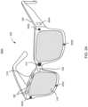
- Figure 3A is a perspective view 300A of a near-eye display device 300 in the form of a pair of glasses (or other similar eyewear), according to an example.
- the near-eye display device 300 may be a specific example of near-eye display device 120 of Figure 1 and may be configured to operate as a virtual reality display, an augmented reality (AR) display, and/or a mixed reality (MR) display.
- AR augmented reality
- MR mixed reality
- the near-eye display device 300 may include a frame 305 and a display 310.
- the display 310 may be configured to present media or other content to a user.
- the display 310 may include display electronics and/or display optics, similar to components described with respect to Figures 1-2 .
- the display 310 may include a liquid crystal display (LCD) display panel, a light-emitting diode (LED) display panel, or an optical display panel (e.g., a waveguide display assembly).
- the display 310 may also include any number of optical components, such as waveguides, gratings, lenses, mirrors, etc.
- the display 210 may include a projector, or in place of the display 310 the near-eye display device 300 may include a projector.
- the near-eye display device 300 may further include various sensors 350a, 350b, 350c, 350d, and 350e on or within a frame 305.
- the various sensors 350a-350e may include any number of depth sensors, motion sensors, position sensors, inertial sensors, and/or ambient light sensors, as shown.
- the various sensors 350a-350e may include any number of image sensors configured to generate image data representing different fields of views in one or more different directions.
- the various sensors 350a-350e may be used as input devices to control or influence the displayed content of the near-eye display device, and/or to provide an interactive virtual reality (VR), augmented reality (AR), and/or mixed reality (MR) experience to a user of the near-eye display device 300.
- the various sensors 350a-350e may also be used for stereoscopic imaging or other similar application.
- the near-eye display device 300 may further include one or more illuminators 330 to project light into a physical environment.
- the projected light may be associated with different frequency bands (e.g., visible light, infra-red light, ultra-violet light, etc.), and may serve various purposes.
- the one or more illuminator(s) 330 may be used as locators, such as the one or more locators 126 described above with respect to Figures 1-2 .
- the near-eye display device 300 may also include a camera 315 or other image capture unit.
- the camera 315 may capture images of the physical environment in the field of view.
- the captured images may be processed, for example, by a virtual reality engine (e.g., the virtual reality engine 116 of Figure 1 ) to add virtual objects to the captured images or modify physical objects in the captured images, and the processed images may be displayed to the user by the display 310 for augmented reality (AR) and/or mixed reality (MR) applications.
- the near-eye display device 300 may also include eye tracking sensors 312.
- the near-eye display device 300 may include a radar sub-system 318, which may operate at 60 GHz range (e.g., 58.0 to 63.5 GHz with a bandwidth of 5.5 GHz).
- the radar sub-system 318 may provide millimeter level resolution (with signal processing enhancements) at low power consumption levels compared to the camera 315 on the near-eye display device 300.
- the radar sub-system 318 may be used standalone to detect hand or finger gestures, in combination with the camera 315 to activate the camera upon detecting motion or for enhanced gesture detection, and to obtain 3D information, which may be combined with 2D image information from the camera 315 to reconstruct 3D scenes.
- Figure 3B is a top view 300B of a near-eye display device 300 in the form of a pair of glasses (or other similar eyewear), according to an example.
- the near-eye display device 300 may include a frame 305 having a form factor of a pair of eyeglasses.
- the frame 305 supports, for each eye: a fringe projector 314 such as any fringe projector variant considered herein, a display 310 to present content to an eye box 366, eye tracking sensors 312, and one or more illuminators 330.
- the illuminators 330 may be used for illuminating an eye box 366, as well as, for providing glint illumination to the eye.
- a fringe projector 314 may provide a periodic fringe pattern onto a user's eye.
- the display 310 may include a pupil-replicating waveguide to receive the fan of light beams and provide multiple laterally offset parallel copies of each beam of the fan of light beams, thereby extending a projected image over the eye box 366.
- the pupil-replicating waveguide may be transparent or translucent to enable the user to view the outside world together with the images projected into each eye and superimposed with the outside world view.
- the images projected into each eye may include objects disposed with a simulated parallax, so as to appear immersed into the real-world view.
- the image processing and eye position/orientation determination functions may be performed by a central controller, not shown, of the near-eye display device 300.
- the central controller may also provide control signals to the display 310 to generate the images to be displayed to the user, depending on the determined eye positions, eye orientations, gaze directions, eyes vergence, etc.
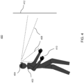
- Figure 4 illustrates direct or indirect gesture detection through a radar on a near-eye display device, according to examples.
- Diagram 400 shows a user 402 wearing a near-eye display device 404 (e.g., a head-mounted display (HMD) device).
- the user 402 may interact with the displayed augmented reality (AR) / virtual reality (VR) content through gesture detection 408 of hand and/or finger gestures 410.
- the gesture detection 408 may be direct or indirect from a nearby reflective surface 412.
- the near-eye display device 404 may include a camera and a radar sub-system.
- the radar sub-system may detect hand/finger gestures 410 using radar waves and detecting motion through time difference and frequency shift measurements.
- the radar sub-system may be positioned on the near-eye display device 404 such that the radar antennas face downward at an angle.
- the radar sub-system may also detect body motion (arm, head, torso, leg, etc.), in some cases.
- the radar sub-system may be used in combination with the outward facing camera on the near-eye display device 404 for more accurate gesture detection, where outputs of the radar sub-system and the camera may be combined in processing captured gestures. Furthermore, the radar sub-system (and the camera) may also detect gestures indirectly from a reflective surface 412. Additionally, the radar sub-system, which consumes less power compared to the camera may be maintained in active mode longer while the camera is turned off, and upon detecting motion (e.g., hand motion), the radar sub-system may be used to turn the camera on and detect gestures through the camera.
- motion e.g., hand motion
- the camera may capture a 2D image of the real scene around the user 402.
- the radar sub-system may obtain depth information associated with the real scene, and the 2D image and the depth information may be combined by a processor to reconstruct a 3D image of the real scene (for augmented reality (AR) / virtual reality (VR) applications).
- AR augmented reality
- VR virtual reality
- the radar sub-system may be used to detect bio-signals of the user 402 such as breath rate, heart rate, hand or finger tremors or twitching, and provide the results to the processor for health monitoring.
- the processor may forward the detected bio-signals to a health monitoring server, for example, the server of a health care provider.
- the radar sub-system and the camera together may be referred to as a detection system of the near-eye display device detecting (and capturing) gestures, 3D characteristics of a scene around the user, 2D images of the scene, and/or bio-signals of the user.
- Figure 5A illustrates enhanced gesture detection through a combination of a radar and a camera, and activation of a gesture detecting camera through a radar in a near-eye display device, according to examples.
- Diagram 500A shows a gesture 502 (hand or finger gesture) being detected by a radar sub-system (504) or, alternatively, by a combination of radar sub-system (504) and camera (508) for enhanced accuracy.
- the diagram also shows the gesture 502 being detected by the camera (518), where the camera is activated (516) upon detection of a motion (hand or finger) by the radar sub-system (514).
- a radar-on-a-chip may be integrated with a near-eye display device with the radar antenna(s) facing downward at an angle to allow users present their gestures in a natural pose.
- the radar sub-system may employ mm-wave (60 GHz) frequency range, which may allow resolutions down to millimeter level (with signal processing improvements).
- mm-wave 60 GHz
- the radar sub-system may be kept in active mode for longer periods (e.g., as long as the near-eye display device is worn) and used to activate the camera as shown in the second scenario in the diagram 500A.
- Figure 5B illustrates 3D reconstruction of a real scene through a combination of a camera and a radar in a near-eye display device, according to examples.
- Diagram 500B shows a real scene 522 being captured (2D image) by a camera 526 and depth information associated with the scene 522 being captured by the radar sub-system (524). The depth information and the 2D image information may be combined for a 3D reconstruction of the scene (528), which may be presented to the user through the augmented reality (AR) / virtual reality (VR) display (530).
- AR augmented reality
- VR virtual reality
- the radar sub-system may capture depth information for larger portions or an entirety of the scene 522 and a full 3D reconstruction of the scene 522 may be created.
- the radar sub-system may focus on a small portion of the scene and assist in 3D motions associated with the scene.
- the scene may include a cup and the user may grab and move the cup (e.g., drinking motion).
- the radar sub-system may track the cup's motion and that information may be used to accurately recreate the cup (and its motion) in a virtual reconstruction of the scene.
- FIG. 5C illustrates bio-signal detection by a radar in a near-eye display device for camera activation or health monitoring, according to examples.
- Diagram 500C shows a user 542 wearing a near-eye display device 544 with a radar sub-system 546.
- the radar sub-system 546 may be used for bio-signal detection (548) directly or indirectly from a reflective surface 554.
- the radar sub-system's detection of the bio-signal may be used for health monitoring 552 and/or to activate the camera (550) to capture the moment.
- the radar sub-system 546 may be used to detect bio-signal(s) of the user such as breath rate, heart rate, tremors or twitching of hands or fingers, etc. The detection may be used for health monitoring (552), where captured bio-signals may be stored and/or processed locally or transmitted by the near-eye display device to a server (e.g., a health care provider's server). In other examples, the radar sub-system 546 may capture a bio-signal, which may be over a predefined threshold (e.g., breath rate), and activate the camera to capture "the moment". For example, if the user's breath rate suddenly increases, an image (or video) of the environment may provide valuable context to the user or a health care provider.
- a predefined threshold e.g., breath rate
- Figure 6 illustrates a flow diagram for a method of gesture and 3D scene capture and detection through a radar and/or a camera on a near-eye display device, according to some examples.
- the method 600 is provided by way of example, as there may be a variety of ways to carry out the method described herein. Although the method 600 is primarily described as being performed by the components of Figures 2-3B , the method 600 may be executed or otherwise performed by one or more processing components of another system or a combination of systems.
- Each block shown in Figure 6 may further represent one or more processes, methods, or subroutines, and one or more of the blocks (e.g., the selection process) may include machine readable instructions stored on a non-transitory computer readable medium and executed by a processor or other type of processing circuit to perform one or more operations described herein.
- a hand/finger gesture or a motion of hand/finger may be detected by a radar sub-system of a near-eye display device.
- the radar sub-system may employ mm-waves (e.g., 60 GHz) with a wide band (e.g., 5.5 GHz) allowing millimeter level resolution.
- Antenna(s) of the radar sub-system may be positioned such that hands / fingers of the user can be detected in a natural pose.
- Gesture(s) detected by the radar sub-system may be used as input for one or more applications executed on the near-eye display device.
- an outward facing camera of the near-eye display device may be activated upon detection of a hand or finger motion by the radar sub-system.
- the radar sub-system consumes substantially less power compared to the camera.
- the radar sub-system may be kept active for longer periods while the camera is turned off and activated upon detection of the motion by the radar sub-system.
- the gesture or a scene around the user may be captured by the activated camera.
- Gestures may be detected by a combination of the camera and the radar sub-system for enhanced accuracy as shown in block 612.
- a 2D image of the scene captured by the camera may be complemented by depth information captured by the radar sub-system in order to reconstruct a 3D image of the scene as shown in block 608.
- the radar sub-system may capture health information through bio-signals such as breath rate, heart rate, etc., which may be used for health monitoring as shown in block 610.
- a method of making a near-eye display device with a radar and a camera is described herein.
- a system of making the near-eye display device is also described herein.
- a non-transitory computer-readable storage medium may have an executable stored thereon, which when executed instructs a processor to perform the methods described herein.
- the methods and systems as described herein may be directed mainly to digital content, such as videos or interactive media, it should be appreciated that the methods and systems as described herein may be used for other types of content or scenarios as well.
- Other applications or uses of the methods and systems as described herein may also include social networking, marketing, content-based recommendation engines, and/or other types of knowledge or data-driven systems.
Landscapes
- Engineering & Computer Science (AREA)
- Remote Sensing (AREA)
- Radar, Positioning & Navigation (AREA)
- Physics & Mathematics (AREA)
- General Physics & Mathematics (AREA)
- General Engineering & Computer Science (AREA)
- Theoretical Computer Science (AREA)
- Computer Networks & Wireless Communication (AREA)
- Health & Medical Sciences (AREA)
- Human Computer Interaction (AREA)
- Life Sciences & Earth Sciences (AREA)
- Cardiology (AREA)
- Physiology (AREA)
- Biomedical Technology (AREA)
- Electromagnetism (AREA)
- General Health & Medical Sciences (AREA)
- Pathology (AREA)
- Veterinary Medicine (AREA)
- Public Health (AREA)
- Optics & Photonics (AREA)
- Animal Behavior & Ethology (AREA)
- Surgery (AREA)
- Molecular Biology (AREA)
- Medical Informatics (AREA)
- Heart & Thoracic Surgery (AREA)
- Biophysics (AREA)
- Pulmonology (AREA)
- Dermatology (AREA)
- Neurology (AREA)
- Neurosurgery (AREA)
- User Interface Of Digital Computer (AREA)
Abstract
Description
- This patent application relates generally to near-eye display devices, and in particular, gesture and three-dimensional (3D) scene capture and detection through a radar and/or a camera on a near-eye display device.
- With recent advances in technology, prevalence and proliferation of content creation and delivery has increased greatly in recent years. In particular, interactive content such as virtual reality (VR) content, augmented reality (AR) content, mixed reality (MR) content, and content within and associated with a real and/or virtual environment (e.g., a "metaverse") has become appealing to consumers.
- To facilitate delivery of this and other related content, service providers have endeavored to provide various forms of wearable display systems. One such example may be a head-mounted display (HMD) device, such as a wearable eyewear, a wearable headset, or eyeglasses. In some examples, the head-mounted display (HMD) device may project or direct light to may display virtual objects or combine images of real objects with virtual objects, as in virtual reality (VR), augmented reality (AR), or mixed reality (MR) applications. For example, in an AR system, a user may view both images of virtual objects (e.g., computer-generated images (CGIs)) and the surrounding environment. Head-mounted display (HMD) devices may also present interactive content, where a user's (wearer's) gaze may be used as input for the interactive content.
- In accordance with a first aspect, there is provided a detection system for a near-eye display device, comprising:
- a radar sub-system configured to detect a gesture, wherein the radar sub-system comprises at least one antenna, a radio frequency (RF) front end, RF processing circuitry, or digital processing circuitry;
- an image sensor configured to capture a two-dimensional (2D) image of the detected gesture; and
- a processor communicatively coupled to the radar sub-system and the image sensor, the processor to:
- activate the image sensor upon detection of the gesture by the radar sub-system; and
- provide an input to an application executed at the near-eye display device based on the detected gesture.
- The gesture may comprise at least one of a hand gesture, a finger gesture, or a body gesture.
- The radar sub-system may be configured to detect the gesture directly or indirectly from a nearby reflective surface.
- An antenna of the radar sub-system may be positioned downward from a head of a user and at a predefined angle to detect the gesture while the user is in a natural pose.
- The image sensor may comprise an outward-facing camera configured to capture the 2D image of the gesture directly or indirectly from a nearby reflective surface.
- The processor may be further configured to:
compare an output of the radar sub-system and an output of the image sensor so as to enhance an accuracy of the detected gesture. - The radar sub-system may be a millimeter-wave radar sub-system.
- In accordance with a second aspect, there is provided a detection system for a near-eye display device, comprising:
- a radar sub-system configured to capture a depth characteristic of a scene around a user wearing the near-eye display device, wherein the radar sub-system comprises at least one antenna, a radio frequency (RF) front end, RF processing circuitry, or digital processing circuitry;
- an image sensor configured to capture a two-dimensional (2D) image of the scene; and
- a processor communicatively coupled to the radar sub-system and the image sensor, the processor to:
- receive the 2D image from the image sensor and the depth characteristic from the radar sub-system; and
- reconstruct a three-dimensional (3D) image of the scene based on the 2D image and the depth characteristic.
- The depth characteristic may comprise depth information associated with at least one object in the scene.
- The radar sub-system may comprise a millimeter-wave radar sub-system that provides millimeter level spatial resolution.
- The radar sub-system may employ 58.0 GHz to 63.5 GHz frequency range with a bandwidth of 5.5 GHz.
- The processor may be further configured to provide the reconstructed 3D image of the scene to a display of the near-eye display device.
- In accordance with a third aspect, there is provided a detection system for a near-eye display device, comprising:
- a radar sub-system configured to detect a bio-signal of a user wearing the near-eye display device, wherein the radar sub-system comprises at least one antenna, a radio frequency (RF) front end, RF processing circuitry, or digital processing circuitry; and
- a processor communicatively coupled to the radar sub-system, the processor being configured to:
provide the detected bio-signal to a health monitoring server. - The bio-signal may comprise at least one of a breath rate, a heart rate, a twitch or a tremor.
- The detection system may further comprise:
an image sensor configured to capture an image, wherein the processor is further configured to: - activate the image sensor upon detection of the bio-signal by the radar sub-system; and
- instruct the image sensor to capture the image.
- The image sensor may comprise an outward-facing camera configured to capture the image directly or indirectly from a nearby reflective surface.
- The captured image may comprise a scene around the user or an image of the user.
- An antenna of the radar sub-system may be positioned downward from a head of the user and at a predefined angle to detect the bio-signal while the user is in a natural pose.
- An antenna of the radar sub-system may be positioned to detect the bio-signal indirectly from a nearby reflective surface.
- The radar sub-system may comprise a millimeter-wave radar sub-system.
- It will be appreciated that any features described herein as being suitable for incorporation into one or more aspects are intended to be generalizable across any and all aspects described herein. Other aspects of the present disclosure can be understood by those skilled in the art in light of the description, the claims and the drawings. The foregoing general description and the following detailed description are exemplary and explanatory only and are not restrictive of the claims.
- Features of the present disclosure are illustrated by way of example and not limited in the following figures, in which like numerals indicate like elements. One skilled in the art will readily recognize from the following that alternative examples of the structures and methods illustrated in the figures can be employed without departing from the principles described herein.
-
Figure 1 illustrates a block diagram of an artificial reality system environment including a near-eye display device, according to an example. -
Figure 2 illustrates a perspective view of a near-eye display device in the form of a head-mounted display (HMD) device, according to an example. -
Figures 3A and3B illustrate a perspective view and a top view of a near-eye display device in the form of a pair of glasses, according to an example. -
Figure 4 illustrates direct or indirect gesture detection through a radar on a near-eye display device, according to examples. -
Figure 5A illustrates enhanced gesture detection through a combination of a radar and a camera, and activation of a gesture detecting camera through a radar in a near-eye display device, according to examples. -
Figure 5B illustrates 3D reconstruction of a real scene through a combination of a camera and a radar in a near-eye display device, according to examples. -
Figure 5C illustrates bio-signal detection by a radar in a near-eye display device for camera activation or health monitoring, according to examples. -
Figure 6 illustrates a flow diagram for a method of gesture and 3D scene capture and detection through a radar and/or a camera on a near-eye display device, according to some examples. - For simplicity and illustrative purposes, the present application is described by referring mainly to examples thereof. In the following description, numerous specific details are set forth in order to provide a thorough understanding of the present application. It will be readily apparent, however, that the present application may be practiced without limitation to these specific details. In other instances, some methods and structures readily understood by one of ordinary skill in the art have not been described in detail so as not to unnecessarily obscure the present application. As used herein, the terms "a" and "an" are intended to denote at least one of a particular element, the term "includes" means includes but not limited to, the term "including" means including but not limited to, and the term "based on" means based at least in part on.
- As used herein, "radar" refers to an electromagnetic sensor for detecting, locating, tracking, and recognizing objects of various kinds at a distance by transmitting electromagnetic energy toward the objects and observing the echoes returned from the objects. A "real scene" refers to a physical environment around a user wearing augmented reality (AR) / virtual reality (VR) display device such as a near-eye display device. A "virtual scene" refers to a computer generated image of a scene and/or objects that is displayed through the near-eye display device to the user. A "bio-signal" refers to any biometric characteristic of a person that may be detected through a radar, a camera, or other device. Examples of bio-signals include, but are not limited to, hear rate, breath rate, skin movements, muscle contractions, head shaking, hand or finger tremors, and similar ones.
- Augmented reality (AR) / virtual reality (VR) near-eye display devices, also referred to as smart glasses, commonly employ capacitive touch technology as a primary user input. Thus, a user needs to raise and hold their hand to the glass temple arm and swipe fingers in close contact with the smart glass. Supported gestures using this technique are limited, and the posture may be deemed unnatural for some users. While some smart glasses may be paired with a wrist input device employing tactile input or electromyography technology, such accessory devices may not be available to all the users.
- In some examples of the present disclosure, a wearable device such as an augmented reality (AR) / virtual reality (VR) near-eye display device may employ radar technology to detect gestures or obtain depth information associated with a real scene around the user. An on-board radar sub-system may use time difference, frequency shift, etc. to detect motion such as hand or finger gestures, which may be used as input related to different functions of the near-eye display device. Due to low power consumption, the radar sub-system may be maintained in active mode for longer periods and also be used to activate an on-board camera. In some cases, the radar sub-system may obtain depth information associated with the real scene around the user, and a two-dimensional (2D) image of the real scene may be captured by the on-board camera. The radar sub-system and camera outputs may then be combined to reconstruct a three-dimensional (3D) image of the real scene. In further examples, bio-signal(s) of the user such as breath rate, heart rate, tremors, twitching, etc. may also be captured by the radar sub-system alone or in combination with the camera and be used for health monitoring.
- While some advantages and benefits of the present disclosure are apparent, other advantages and benefits may include providing near-eye display devices with a wide range of gesture detection and 3D scene reconstruction with low power consumption, health monitoring, and enhanced accuracy in input processing.
-
Figure 1 illustrates a block diagram of an artificialreality system environment 100 including a near-eye display device, according to an example. As used herein, a "near-eye display device" may refer to a device (e.g., an optical device) that may be in close proximity to a user's eye. As used herein, "artificial reality" may refer to aspects of, among other things, a "metaverse" or an environment of real and virtual elements and may include use of technologies associated with virtual reality (VR), augmented reality (AR), and/or mixed reality (MR). As used herein a "user" may refer to a user or wearer of a "near-eye display device." - As shown in
Figure 1 , the artificialreality system environment 100 may include a near-eye display device 120, an optionalexternal imaging device 150, and an optional input/output interface 140, each of which may be coupled to aconsole 110. Theconsole 110 may be optional in some instances as the functions of theconsole 110 may be integrated into the near-eye display device 120. In some examples, the near-eye display device 120 may be a head-mounted display (HMD) that presents content to a user. - In some instances, for a near-eye display system, it may generally be desirable to expand an eye box, reduce display haze, improve image quality (e.g., resolution and contrast), reduce physical size, increase power efficiency, and increase or expand field of view (FOV). As used herein, "field of view" (FOV) may refer to an angular range of an image as seen by a user, which is typically measured in degrees as observed by one eye (for a monocular head-mounted display (HMD)) or both eyes (for binocular head-mounted displays (HMDs)). Also, as used herein, an "eye box" may be a two-dimensional box that may be positioned in front of the user's eye from which a displayed image from an image source may be viewed.
- In some examples, in a near-eye display system, light from a surrounding environment may traverse a "see-through" region of a waveguide display (e.g., a transparent substrate) to reach a user's eyes. For example, in a near-eye display system, light of projected images may be coupled into a transparent substrate of a waveguide, propagate within the waveguide, and be coupled or directed out of the waveguide at one or more locations to replicate exit pupils and expand the eye box.
- In some examples, the near-
eye display device 120 may include one or more rigid bodies, which may be rigidly or non-rigidly coupled to each other. In some examples, a rigid coupling between rigid bodies may cause the coupled rigid bodies to act as a single rigid entity, while in other examples, a non-rigid coupling between rigid bodies may allow the rigid bodies to move relative to each other. - In some examples, the near-
eye display device 120 may be implemented in any suitable form-factor, including a head-mounted display (HMD), a pair of glasses, or other similar wearable eyewear or device. Examples of the near-eye display device 120 are further described below with respect toFigures 2 and3 . Additionally, in some examples, the functionality described herein may be used in a head-mounted display (HMD) or headset that may combine images of an environment external to the near-eye display device 120 and artificial reality content (e.g., computer-generated images). Therefore, in some examples, the near-eye display device 120 may augment images of a physical, real-world environment external to the near-eye display device 120 with generated and/or overlaid digital content (e.g., images, video, sound, etc.) to present an augmented reality to a user. - In some examples, the near-
eye display device 120 may include any number ofdisplay electronics 122,display optics 124, and aneye tracking unit 130. In some examples, the near-eye display device 120 may also include one ormore locators 126, one ormore position sensors 128, an inertial measurement unit (IMU) 132, and a radar subs-system 134. In some examples, the near-eye display device 120 may omit any of theeye tracking unit 130, the one ormore locators 126, the one ormore position sensors 128, and the inertial measurement unit (IMU) 132, or may include additional elements. - In some examples, the
display electronics 122 may display or facilitate the display of images to the user according to data received from, for example, theoptional console 110. In some examples, thedisplay electronics 122 may include one or more display panels. In some examples, thedisplay electronics 122 may include any number of pixels to emit light of a predominant color such as red, green, blue, white, or yellow. In some examples, thedisplay electronics 122 may display a three-dimensional (3D) image, e.g., using stereoscopic effects produced by two-dimensional panels, to create a subjective perception of image depth. - In some examples, the near-
eye display device 120 may include a projector (not shown), which may form an image in angular domain for direct observation by a viewer's eye through a pupil. The projector may employ a controllable light source (e.g., a laser source) and a micro-electromechanical system (MEMS) beam scanner to create a light field from, for example, a collimated light beam. In some examples, the same projector or a different projector may be used to project a fringe pattern on the eye, which may be captured by a camera and analyzed (e.g., by the eye tracking unit 130) to determine a position of the eye (the pupil), a gaze, etc. - In some examples, the
display optics 124 may display image content optically (e.g., using optical waveguides and/or couplers) or magnify image light received from thedisplay electronics 122, correct optical errors associated with the image light, and/or present the corrected image light to a user of the near-eye display device 120. In some examples, thedisplay optics 124 may include a single optical element or any number of combinations of various optical elements as well as mechanical couplings to maintain relative spacing and orientation of the optical elements in the combination. In some examples, one or more optical elements in thedisplay optics 124 may have an optical coating, such as an anti-reflective coating, a reflective coating, a filtering coating, and/or a combination of different optical coatings. - In some examples, the
display optics 124 may also be designed to correct one or more types of optical errors, such as two-dimensional optical errors, three-dimensional optical errors, or any combination thereof. Examples of two-dimensional errors may include barrel distortion, pincushion distortion, longitudinal chromatic aberration, and/or transverse chromatic aberration. Examples of three-dimensional errors may include spherical aberration, chromatic aberration field curvature, and astigmatism. - In some examples, the one or
more locators 126 may be objects located in specific positions relative to one another and relative to a reference point on the near-eye display device 120. In some examples, theoptional console 110 may identify the one ormore locators 126 in images captured by the optionalexternal imaging device 150 to determine the artificial reality headset's position, orientation, or both. The one ormore locators 126 may each be a light-emitting diode (LED), a corner cube reflector, a reflective marker, a type of light source that contrasts with an environment in which the near-eye display device 120 operates, or any combination thereof. - In some examples, the
external imaging device 150 may include one or more cameras, one or more video cameras, any other device capable of capturing images including the one ormore locators 126, or any combination thereof. The optionalexternal imaging device 150 may be configured to detect light emitted or reflected from the one ormore locators 126 in a field of view of the optionalexternal imaging device 150. - In some examples, the one or
more position sensors 128 may generate one or more measurement signals in response to motion of the near-eye display device 120. Examples of the one ormore position sensors 128 may include any number of accelerometers, gyroscopes, magnetometers, and/or other motion-detecting or error-correcting sensors, or any combination thereof. - In some examples, the inertial measurement unit (IMU) 132 may be an electronic device that generates fast calibration data based on measurement signals received from the one or
more position sensors 128. The one ormore position sensors 128 may be located external to the inertial measurement unit (IMU) 132, internal to the inertial measurement unit (IMU) 132, or any combination thereof. Based on the one or more measurement signals from the one ormore position sensors 128, the inertial measurement unit (IMU) 132 may generate fast calibration data indicating an estimated position of the near-eye display device 120 that may be relative to an initial position of the near-eye display device 120. For example, the inertial measurement unit (IMU) 132 may integrate measurement signals received from accelerometers over time to estimate a velocity vector and integrate the velocity vector over time to determine an estimated position of a reference point on the near-eye display device 120. Alternatively, the inertial measurement unit (IMU) 132 may provide the sampled measurement signals to theoptional console 110, which may determine the fast calibration data. - The
eye tracking unit 130 may include one or more eye tracking systems. As used herein, "eye tracking" may refer to determining an eye's position or relative position, including orientation, location, and/or gaze of a user's eye. In some examples, an eye tracking system may include an imaging system that captures one or more images of an eye and may optionally include a light emitter, which may generate light (e.g., a fringe pattern) that is directed to an eye such that light reflected by the eye may be captured by the imaging system (e.g., a camera). In other examples, theeye tracking unit 130 may capture reflected radio waves emitted by a miniature radar unit. These data associated with the eye may be used to determine or predict eye position, orientation, movement, location, and/or gaze. - In some examples, the
radar sub-system 134 may be a radar-on-a-chip, a radar transceiver, receive/transmit antenna(s), RF front end circuitry, RF processing circuitry, filters, and/or digital signal processing circuitry integrated on a single ship. The radar sub-system may operate at 60 GHz range (e.g., 58.0 to 63.5 GHz with a bandwidth of 5.5 GHz). Such a radar sub-system may provide millimeter level spatial resolution (with signal processing enhancements) at low power consumption levels compared to a camera on the near-eye display device 120. Theradar sub-system 134 may be used standalone to detect hand or finger gestures, in combination with a camera to activate the camera upon detecting motion or for enhanced gesture detection, and to obtain 3D information, which may be combined with 2D image information from the camera to reconstruct 3D scenes. - In some examples, the input/
output interface 140 may be a device that allows a user to send action requests to theoptional console 110. As used herein, an "action request" may be a request to perform a particular action. For example, an action request may be to start or to end an application or to perform a particular action within the application. The input/output interface 140 may include one or more input devices. Example input devices may include a keyboard, a mouse, a game controller, a glove, a button, a touch screen, or any other suitable device for receiving action requests and communicating the received action requests to theoptional console 110. In some examples, an action request received by the input/output interface 140 may be communicated to theoptional console 110, which may perform an action corresponding to the requested action. - In some examples, the
optional console 110 may provide content to the near-eye display device 120 for presentation to the user in accordance with information received from one or more ofexternal imaging device 150, the near-eye display device 120, and the input/output interface 140. For example, in the example shown inFigure 1 , theoptional console 110 may include anapplication store 112, aheadset tracking module 114, avirtual reality engine 116, and aneye tracking module 118. Some examples of theoptional console 110 may include different or additional modules than those described in conjunction withFigure 1 . Functions further described below may be distributed among components of theoptional console 110 in a different manner than is described here. - In some examples, the
optional console 110 may include a processor and a non-transitory computer-readable storage medium storing instructions executable by the processor. The processor may include multiple processing units executing instructions in parallel. The non-transitory computer-readable storage medium may be any memory, such as a hard disk drive, a removable memory, or a solid-state drive (e.g., flash memory or dynamic random access memory (DRAM)). In some examples, the modules of theoptional console 110 described in conjunction withFigure 1 may be encoded as instructions in the non-transitory computer-readable storage medium that, when executed by the processor, cause the processor to perform the functions further described below. It should be appreciated that theoptional console 110 may or may not be needed or theoptional console 110 may be integrated with or separate from the near-eye display device 120. - In some examples, the
application store 112 may store one or more applications for execution by theoptional console 110. An application may include a group of instructions that, when executed by a processor, generates content for presentation to the user. Examples of the applications may include gaming applications, conferencing applications, video playback application, or other suitable applications. - In some examples, the
virtual reality engine 116 may execute applications within the artificialreality system environment 100 and receive position information of the near-eye display device 120, acceleration information of the near-eye display device 120, velocity information of the near-eye display device 120, predicted future positions of the near-eye display device 120, or any combination thereof from theheadset tracking module 114. In some examples, thevirtual reality engine 116 may also receive estimated eye position and orientation information from theeye tracking module 118. Based on the received information, thevirtual reality engine 116 may determine content to provide to the near-eye display device 120 for presentation to the user. - In some examples, the
eye tracking module 118, which may be implemented as a processor, may receive eye tracking data from theeye tracking unit 130 and determine the position of the user's eye based on the eye tracking data. In some examples, the position of the eye may include an eye's orientation, location, or both relative to the near-eye display device 120 or any element thereof. So, in these examples, because the eye's axes of rotation change as a function of the eye's location in its socket, determining the eye's location in its socket may allow theeye tracking module 118 to more accurately determine the eye's orientation. - In some examples, a location of a projector of a display system may be adjusted to enable any number of design modifications. For example, in some instances, a projector may be located in front of a viewer's eye (i.e., "front-mounted" placement). In a front-mounted placement, in some examples, a projector of a display system may be located away from a user's eyes (i.e., "world-side"). In some examples, a head-mounted display (HMD) device may utilize a front-mounted placement to propagate light towards a user's eye(s) to project an image.
-
Figure 2 illustrates a perspective view of a near-eye display device in the form of a head-mounted display (HMD)device 200, according to an example. In some examples, the head-mounted device (HMD)device 200 may be a part of a virtual reality (VR) system, an augmented reality (AR) system, a mixed reality (MR) system, another system that uses displays or wearables, or any combination thereof. In some examples, the head-mounted display (HMD)device 200 may include abody 220 and ahead strap 230.Figure 2 shows abottom side 223, afront side 225, and aleft side 227 of thebody 220 in the perspective view. In some examples, thehead strap 230 may have an adjustable or extendible length. In particular, in some examples, there may be a sufficient space between thebody 220 and thehead strap 230 of the head-mounted display (HMD)device 200 for allowing a user to mount the head-mounted display (HMD)device 200 onto the user's head. For example, the length of thehead strap 230 may be adjustable to accommodate a range of user head sizes. In some examples, the head-mounted display (HMD)device 200 may include additional, fewer, and/or different components. - In some examples, the head-mounted display (HMD)
device 200 may present, to a user, media or other digital content including virtual and/or augmented views of a physical, real-world environment with computer-generated elements. Examples of the media or digital content presented by the head-mounted display (HMD)device 200 may include images (e.g., two-dimensional (2D) or three-dimensional (3D) images), videos (e.g., 2D or 3D videos), audio, or any combination thereof. In some examples, the images and videos may be presented to each eye of a user by one or more display assemblies (not shown inFigure 2 ) enclosed in thebody 220 of the head-mounted display (HMD)device 200. - In some examples, the head-mounted display (HMD)
device 200 may include various sensors (not shown), such as depth sensors, motion sensors, position sensors, and/or eye tracking sensors. Some of these sensors may use any number of structured or unstructured light patterns for sensing purposes. In some examples, the head-mounted display (HMD)device 200 may include an input/output interface 140 for communicating with aconsole 110, as described with respect toFigure 1 . In some examples, the head-mounted display (HMD)device 200 may include a virtual reality engine (not shown), but similar to thevirtual reality engine 116 described with respect toFigure 1 , that may execute applications within the head-mounted display (HMD)device 200 and receive depth information, position information, acceleration information, velocity information, predicted future positions, or any combination thereof of the head-mounted display (HMD)device 200 from the various sensors. - In some examples, the information received by the
virtual reality engine 116 may be used for producing a signal (e.g., display instructions) to the one or more display assemblies. In some examples, the head-mounted display (HMD)device 200 may include locators (not shown), but similar to thelocators 126 described inFigure 1 , which may be located in fixed positions on thebody 220 of the head-mounted display (HMD)device 200 relative to one another and relative to a reference point. Each of the locators may emit light that is detectable by an external imaging device. This may be useful for the purposes of head tracking or other movement/orientation. It should be appreciated that other elements or components may also be used in addition or in lieu of such locators. - It should be appreciated that in some examples, a projector mounted in a display system may be placed near and/or closer to a user's eye (i.e., "eye-side"). In some examples, and as discussed herein, a projector for a display system shaped liked eyeglasses may be mounted or positioned in a temple arm (i.e., a top far corner of a lens side) of the eyeglasses. It should be appreciated that, in some instances, utilizing a back-mounted projector placement may help to reduce size or bulkiness of any required housing required for a display system, which may also result in a significant improvement in user experience for a user.
- In some examples, the head-mounted display (HMD)
device 200 may include aradar sub-system 218, which may operate at 60 GHz range (e.g., 58.0 to 63.5 GHz with a bandwidth of 5.5 GHz). Theradar sub-system 218 may provide millimeter level spatial resolution (with signal processing enhancements) at low power consumption levels compared to thecamera 215 on the head-mounted display (HMD)device 200. Theradar sub-system 218 may be used standalone to detect hand or finger gestures, in combination with thecamera 215 to activate the camera upon detecting motion or for enhanced gesture detection, and to obtain 3D information, which may be combined with 2D image information from thecamera 215 to reconstruct 3D scenes. -
Figure 3A is aperspective view 300A of a near-eye display device 300 in the form of a pair of glasses (or other similar eyewear), according to an example. In some examples, the near-eye display device 300 may be a specific example of near-eye display device 120 ofFigure 1 and may be configured to operate as a virtual reality display, an augmented reality (AR) display, and/or a mixed reality (MR) display. - In some examples, the near-
eye display device 300 may include aframe 305 and adisplay 310. In some examples, thedisplay 310 may be configured to present media or other content to a user. In some examples, thedisplay 310 may include display electronics and/or display optics, similar to components described with respect toFigures 1-2 . For example, as described above with respect to the near-eye display device 120 ofFigure 1 , thedisplay 310 may include a liquid crystal display (LCD) display panel, a light-emitting diode (LED) display panel, or an optical display panel (e.g., a waveguide display assembly). In some examples, thedisplay 310 may also include any number of optical components, such as waveguides, gratings, lenses, mirrors, etc. In other examples, thedisplay 210 may include a projector, or in place of thedisplay 310 the near-eye display device 300 may include a projector. - In some examples, the near-
eye display device 300 may further include various sensors 350a, 350b, 350c, 350d, and 350e on or within aframe 305. In some examples, the various sensors 350a-350e may include any number of depth sensors, motion sensors, position sensors, inertial sensors, and/or ambient light sensors, as shown. In some examples, the various sensors 350a-350e may include any number of image sensors configured to generate image data representing different fields of views in one or more different directions. In some examples, the various sensors 350a-350e may be used as input devices to control or influence the displayed content of the near-eye display device, and/or to provide an interactive virtual reality (VR), augmented reality (AR), and/or mixed reality (MR) experience to a user of the near-eye display device 300. In some examples, the various sensors 350a-350e may also be used for stereoscopic imaging or other similar application. - In some examples, the near-
eye display device 300 may further include one ormore illuminators 330 to project light into a physical environment. The projected light may be associated with different frequency bands (e.g., visible light, infra-red light, ultra-violet light, etc.), and may serve various purposes. In some examples, the one or more illuminator(s) 330 may be used as locators, such as the one ormore locators 126 described above with respect toFigures 1-2 . - In some examples, the near-
eye display device 300 may also include acamera 315 or other image capture unit. Thecamera 315, for instance, may capture images of the physical environment in the field of view. In some instances, the captured images may be processed, for example, by a virtual reality engine (e.g., thevirtual reality engine 116 ofFigure 1 ) to add virtual objects to the captured images or modify physical objects in the captured images, and the processed images may be displayed to the user by thedisplay 310 for augmented reality (AR) and/or mixed reality (MR) applications. The near-eye display device 300 may also includeeye tracking sensors 312. - In some examples, the near-
eye display device 300 may include aradar sub-system 318, which may operate at 60 GHz range (e.g., 58.0 to 63.5 GHz with a bandwidth of 5.5 GHz). Theradar sub-system 318 may provide millimeter level resolution (with signal processing enhancements) at low power consumption levels compared to thecamera 315 on the near-eye display device 300. Theradar sub-system 318 may be used standalone to detect hand or finger gestures, in combination with thecamera 315 to activate the camera upon detecting motion or for enhanced gesture detection, and to obtain 3D information, which may be combined with 2D image information from thecamera 315 to reconstruct 3D scenes. -
Figure 3B is atop view 300B of a near-eye display device 300 in the form of a pair of glasses (or other similar eyewear), according to an example. In some examples, the near-eye display device 300 may include aframe 305 having a form factor of a pair of eyeglasses. Theframe 305 supports, for each eye: a fringe projector 314 such as any fringe projector variant considered herein, adisplay 310 to present content to aneye box 366,eye tracking sensors 312, and one ormore illuminators 330. Theilluminators 330 may be used for illuminating aneye box 366, as well as, for providing glint illumination to the eye. A fringe projector 314 may provide a periodic fringe pattern onto a user's eye. Thedisplay 310 may include a pupil-replicating waveguide to receive the fan of light beams and provide multiple laterally offset parallel copies of each beam of the fan of light beams, thereby extending a projected image over theeye box 366. - In some examples, the pupil-replicating waveguide may be transparent or translucent to enable the user to view the outside world together with the images projected into each eye and superimposed with the outside world view. The images projected into each eye may include objects disposed with a simulated parallax, so as to appear immersed into the real-world view.
- In some examples, the image processing and eye position/orientation determination functions may be performed by a central controller, not shown, of the near-
eye display device 300. The central controller may also provide control signals to thedisplay 310 to generate the images to be displayed to the user, depending on the determined eye positions, eye orientations, gaze directions, eyes vergence, etc. -
Figure 4 illustrates direct or indirect gesture detection through a radar on a near-eye display device, according to examples. Diagram 400 shows auser 402 wearing a near-eye display device 404 (e.g., a head-mounted display (HMD) device). Theuser 402 may interact with the displayed augmented reality (AR) / virtual reality (VR) content throughgesture detection 408 of hand and/or finger gestures 410. Thegesture detection 408 may be direct or indirect from a nearbyreflective surface 412. - In some examples, the near-eye display device 404 (head-mounted display (HMD) device) may include a camera and a radar sub-system. The radar sub-system may detect hand/finger gestures 410 using radar waves and detecting motion through time difference and frequency shift measurements. To allow for natural poses for the user 402 (not to have them put their hands up against the near-
eye display device 404 and make gestures with hands on their lap, etc.), the radar sub-system may be positioned on the near-eye display device 404 such that the radar antennas face downward at an angle. The radar sub-system may also detect body motion (arm, head, torso, leg, etc.), in some cases. - In other examples, the radar sub-system may be used in combination with the outward facing camera on the near-
eye display device 404 for more accurate gesture detection, where outputs of the radar sub-system and the camera may be combined in processing captured gestures. Furthermore, the radar sub-system (and the camera) may also detect gestures indirectly from areflective surface 412. Additionally, the radar sub-system, which consumes less power compared to the camera may be maintained in active mode longer while the camera is turned off, and upon detecting motion (e.g., hand motion), the radar sub-system may be used to turn the camera on and detect gestures through the camera. - In yet other examples, the camera may capture a 2D image of the real scene around the
user 402. The radar sub-system may obtain depth information associated with the real scene, and the 2D image and the depth information may be combined by a processor to reconstruct a 3D image of the real scene (for augmented reality (AR) / virtual reality (VR) applications). - In further examples, the radar sub-system may be used to detect bio-signals of the
user 402 such as breath rate, heart rate, hand or finger tremors or twitching, and provide the results to the processor for health monitoring. The processor may forward the detected bio-signals to a health monitoring server, for example, the server of a health care provider. The radar sub-system and the camera together may be referred to as a detection system of the near-eye display device detecting (and capturing) gestures, 3D characteristics of a scene around the user, 2D images of the scene, and/or bio-signals of the user. -
Figure 5A illustrates enhanced gesture detection through a combination of a radar and a camera, and activation of a gesture detecting camera through a radar in a near-eye display device, according to examples. Diagram 500A shows a gesture 502 (hand or finger gesture) being detected by a radar sub-system (504) or, alternatively, by a combination of radar sub-system (504) and camera (508) for enhanced accuracy. The diagram also shows thegesture 502 being detected by the camera (518), where the camera is activated (516) upon detection of a motion (hand or finger) by the radar sub-system (514). - In some examples, a radar-on-a-chip may be integrated with a near-eye display device with the radar antenna(s) facing downward at an angle to allow users present their gestures in a natural pose. The radar sub-system may employ mm-wave (60 GHz) frequency range, which may allow resolutions down to millimeter level (with signal processing improvements). As the radar sub-system consumes substantially less power compared to the camera, the radar sub-system may be kept in active mode for longer periods (e.g., as long as the near-eye display device is worn) and used to activate the camera as shown in the second scenario in the diagram 500A.
-
Figure 5B illustrates 3D reconstruction of a real scene through a combination of a camera and a radar in a near-eye display device, according to examples. Diagram 500B shows areal scene 522 being captured (2D image) by a camera 526 and depth information associated with thescene 522 being captured by the radar sub-system (524). The depth information and the 2D image information may be combined for a 3D reconstruction of the scene (528), which may be presented to the user through the augmented reality (AR) / virtual reality (VR) display (530). - In some examples, the radar sub-system may capture depth information for larger portions or an entirety of the
scene 522 and a full 3D reconstruction of thescene 522 may be created. In other examples, the radar sub-system may focus on a small portion of the scene and assist in 3D motions associated with the scene. For example, the scene may include a cup and the user may grab and move the cup (e.g., drinking motion). The radar sub-system may track the cup's motion and that information may be used to accurately recreate the cup (and its motion) in a virtual reconstruction of the scene. -
Figure 5C illustrates bio-signal detection by a radar in a near-eye display device for camera activation or health monitoring, according to examples. Diagram 500C shows auser 542 wearing a near-eye display device 544 with aradar sub-system 546. Theradar sub-system 546 may be used for bio-signal detection (548) directly or indirectly from areflective surface 554. The radar sub-system's detection of the bio-signal may be used forhealth monitoring 552 and/or to activate the camera (550) to capture the moment. - In some examples, the
radar sub-system 546 may be used to detect bio-signal(s) of the user such as breath rate, heart rate, tremors or twitching of hands or fingers, etc. The detection may be used for health monitoring (552), where captured bio-signals may be stored and/or processed locally or transmitted by the near-eye display device to a server (e.g., a health care provider's server). In other examples, theradar sub-system 546 may capture a bio-signal, which may be over a predefined threshold (e.g., breath rate), and activate the camera to capture "the moment". For example, if the user's breath rate suddenly increases, an image (or video) of the environment may provide valuable context to the user or a health care provider. -
Figure 6 illustrates a flow diagram for a method of gesture and 3D scene capture and detection through a radar and/or a camera on a near-eye display device, according to some examples. Themethod 600 is provided by way of example, as there may be a variety of ways to carry out the method described herein. Although themethod 600 is primarily described as being performed by the components ofFigures 2-3B , themethod 600 may be executed or otherwise performed by one or more processing components of another system or a combination of systems. Each block shown inFigure 6 may further represent one or more processes, methods, or subroutines, and one or more of the blocks (e.g., the selection process) may include machine readable instructions stored on a non-transitory computer readable medium and executed by a processor or other type of processing circuit to perform one or more operations described herein. - At
block 602, a hand/finger gesture or a motion of hand/finger may be detected by a radar sub-system of a near-eye display device. The radar sub-system may employ mm-waves (e.g., 60 GHz) with a wide band (e.g., 5.5 GHz) allowing millimeter level resolution. Antenna(s) of the radar sub-system may be positioned such that hands / fingers of the user can be detected in a natural pose. Gesture(s) detected by the radar sub-system may be used as input for one or more applications executed on the near-eye display device. - At
block 604, an outward facing camera of the near-eye display device may be activated upon detection of a hand or finger motion by the radar sub-system. As mentioned herein, the radar sub-system consumes substantially less power compared to the camera. Thus, the radar sub-system may be kept active for longer periods while the camera is turned off and activated upon detection of the motion by the radar sub-system. - At
block 606, the gesture or a scene around the user may be captured by the activated camera. Gestures may be detected by a combination of the camera and the radar sub-system for enhanced accuracy as shown inblock 612. In some examples, a 2D image of the scene captured by the camera may be complemented by depth information captured by the radar sub-system in order to reconstruct a 3D image of the scene as shown inblock 608. Furthermore, the radar sub-system may capture health information through bio-signals such as breath rate, heart rate, etc., which may be used for health monitoring as shown inblock 610. - According to examples, a method of making a near-eye display device with a radar and a camera is described herein. A system of making the near-eye display device is also described herein. A non-transitory computer-readable storage medium may have an executable stored thereon, which when executed instructs a processor to perform the methods described herein.
- In the foregoing description, various examples are described, including devices, systems, methods, and the like. For the purposes of explanation, specific details are set forth in order to provide a thorough understanding of examples of the disclosure. However, it will be apparent that various examples may be practiced without these specific details. For example, devices, systems, structures, assemblies, methods, and other components may be shown as components in block diagram form in order not to obscure the examples in unnecessary detail. In other instances, well-known devices, processes, systems, structures, and techniques may be shown without necessary detail in order to avoid obscuring the examples.
- The figures and description are not intended to be restrictive. The terms and expressions that have been employed in this disclosure are used as terms of description and not of limitation, and there is no intention in the use of such terms and expressions of excluding any equivalents of the features shown and described or portions thereof. The word "example" is used herein to mean "serving as an example, instance, or illustration." Any embodiment or design described herein as "example' is not necessarily to be construed as preferred or advantageous over other embodiments or designs.
- Although the methods and systems as described herein may be directed mainly to digital content, such as videos or interactive media, it should be appreciated that the methods and systems as described herein may be used for other types of content or scenarios as well. Other applications or uses of the methods and systems as described herein may also include social networking, marketing, content-based recommendation engines, and/or other types of knowledge or data-driven systems.
Claims (15)
- A detection system for a near-eye display device, comprising:a radar sub-system configured to detect a gesture, wherein the radar sub-system comprises at least one antenna, a radio frequency (RF) front end, RF processing circuitry, or digital processing circuitry;an image sensor configured to capture a two-dimensional (2D) image of the detected gesture; anda processor communicatively coupled to the radar sub-system and the image sensor, the processor to:activate the image sensor upon detection of the gesture by the radar sub-system; andprovide an input to an application executed at the near-eye display device based on the detected gesture.
- The detection system of claim 1, wherein the gesture comprises at least one of a hand gesture, a finger gesture, or a body gesture.
- The detection system of claim 1 or claim 2 and one or more of the following:wherein the radar sub-system is configured to detect the gesture directly or indirectly from a nearby reflective surface;wherein the radar sub-system comprises a millimeter-wave radar sub-system.
- The detection system of any preceding claim, wherein an antenna of the radar sub-system is positioned downward from a head of a user and at a predefined angle to detect the gesture while the user is in a natural pose.
- The detection system of any preceding claim, wherein the image sensor comprises an outward-facing camera configured to capture the 2D image of the gesture directly or indirectly from a nearby reflective surface.
- The detection system of any preceding claim, wherein the processor is further configured to:
compare an output of the radar sub-system and an output of the image sensor so as to enhance an accuracy of the detected gesture. - A detection system for a near-eye display device, comprising:a radar sub-system configured to capture a depth characteristic of a scene around a user wearing the near-eye display device, wherein the radar sub-system comprises at least one antenna, a radio frequency (RF) front end, RF processing circuitry, or digital processing circuitry;an image sensor configured to capture a two-dimensional (2D) image of the scene; anda processor communicatively coupled to the radar sub-system and the image sensor, the processor to:receive the 2D image from the image sensor and the depth characteristic from the radar sub-system; andreconstruct a three-dimensional (3D) image of the scene based on the 2D image and the depth characteristic.
- The detection system of claim 7, wherein the depth characteristic comprises depth information associated with at least one object in the scene.
- The detection system of claim 7 or claim 8, wherein the radar sub-system comprises a millimeter-wave radar sub-system that provides millimeter level spatial resolution;
optionally, wherein the radar sub-system employs 58.0 GHz to 63.5 GHz frequency range with a bandwidth of 5.5 GHz. - The detection system of any one of claims 7 to 9, wherein the processor is further configured to provide the reconstructed 3D image of the scene to a display of the near-eye display device.
- A detection system for a near-eye display device, comprising:a radar sub-system configured to detect a bio-signal of a user wearing the near-eye display device, wherein the radar sub-system comprises at least one antenna, a radio frequency (RF) front end, RF processing circuitry, or digital processing circuitry; anda processor communicatively coupled to the radar sub-system, the processor to:
provide the detected bio-signal to a health monitoring server. - The detection system of claim 11, wherein the bio-signal comprises at least one of a breath rate, a heart rate, a twitch, or a tremor.
- The detection system of claim 12, further comprising:
an image sensor configured to capture an image, wherein the processor is further configured to:activate the image sensor upon detection of the bio-signal by the radar sub-system; andinstruct the image sensor to capture the image; - The detection system of any one of claims 11 to 13, wherein the image sensor comprises an outward-facing camera configured to capture the image directly or indirectly from a nearby reflective surface;
optionally, wherein the captured image comprises a scene around the user or an image of the user. - The detection system of any one of claims 11 to 14 and one or more of the following:wherein an antenna of the radar sub-system is positioned downward from a head of the user and at a predefined angle to detect the bio-signal while the user is in a natural pose;wherein an antenna of the radar sub-system is positioned to detect the bio-signal indirectly from a nearby reflective surface;wherein the radar sub-system comprises a millimeter-wave radar sub-system.
Applications Claiming Priority (1)
| Application Number | Priority Date | Filing Date | Title |
|---|---|---|---|
| US202318115234A | 2023-02-28 | 2023-02-28 |
Publications (2)
| Publication Number | Publication Date |
|---|---|
| EP4425304A2 true EP4425304A2 (en) | 2024-09-04 |
| EP4425304A3 EP4425304A3 (en) | 2024-10-16 |
Family
ID=89772201
Family Applications (1)
| Application Number | Title | Priority Date | Filing Date |
|---|---|---|---|
| EP24154466.7A Withdrawn EP4425304A3 (en) | 2023-02-28 | 2024-01-29 | Radar-assisted three-dimensional (3d) detection for near-eye display devices |
Country Status (2)
| Country | Link |
|---|---|
| EP (1) | EP4425304A3 (en) |
| CN (1) | CN118566900A (en) |
Cited By (1)
| Publication number | Priority date | Publication date | Assignee | Title |
|---|---|---|---|---|
| CN119580081A (en) * | 2025-02-05 | 2025-03-07 | 浙江瀚陆海底系统工程技术有限公司 | A method and system for underwater robot sample identification and grasping |
Family Cites Families (1)
| Publication number | Priority date | Publication date | Assignee | Title |
|---|---|---|---|---|
| US11592907B2 (en) * | 2020-10-20 | 2023-02-28 | Google Llc | Gesture-triggered augmented-reality |
-
2024
- 2024-01-29 EP EP24154466.7A patent/EP4425304A3/en not_active Withdrawn
- 2024-02-27 CN CN202410216526.7A patent/CN118566900A/en active Pending
Cited By (1)
| Publication number | Priority date | Publication date | Assignee | Title |
|---|---|---|---|---|
| CN119580081A (en) * | 2025-02-05 | 2025-03-07 | 浙江瀚陆海底系统工程技术有限公司 | A method and system for underwater robot sample identification and grasping |
Also Published As
| Publication number | Publication date |
|---|---|
| CN118566900A (en) | 2024-08-30 |
| EP4425304A3 (en) | 2024-10-16 |
Similar Documents
| Publication | Publication Date | Title |
|---|---|---|
| JP7177213B2 (en) | Adaptive parameters in image regions based on eye-tracking information | |
| KR101789357B1 (en) | Automatic focus improvement for augmented reality displays | |
| US10120442B2 (en) | Eye tracking using a light field camera on a head-mounted display | |
| US12271514B2 (en) | Mixed reality interaction with eye-tracking techniques | |
| KR20220110205A (en) | Content stabilization for head mounted displays | |
| US12045387B2 (en) | Eye tracking system with in-plane illumination | |
| EP4307028A1 (en) | Optical assembly with micro light emitting diode (led) as eye-tracking near infrared (nir) illumination source | |
| US20230213761A1 (en) | Display systems with gratings oriented to reduce appearances of ghost images | |
| US11743447B2 (en) | Gaze tracking apparatus and systems | |
| US20240126367A1 (en) | Indirect time of flight (tof) depth sensing for eye tracking | |
| US20240069347A1 (en) | System and method using eye tracking illumination | |
| EP4639257A1 (en) | Three-dimensional (3d) compressive sensing based eye tracking | |
| CN118566900A (en) | Radar-assisted three-dimensional (3D) detection for near-eye display devices | |
| US12135429B2 (en) | Pupil-steering for three-dimensional (3D) resolution enhancement in single photon avalanche diode (SPAD) eye tracking (ET) | |
| US12360593B2 (en) | Absolute phase unwrapping for fringe analysis in an eye tracking application | |
| US20250067982A1 (en) | Controllable aperture projection for waveguide display | |
| EP4428601A2 (en) | Line-of-sight (los) communication capability for a near-eye display device | |
| US12544263B2 (en) | Pupil-aware eye tracking for eye safety | |
| US12567682B2 (en) | Compact multiband open-ended slot dipole antenna for a near-eye device | |
| US12189121B2 (en) | Ultrafast illumination for structured light based eye tracking | |
| US20250239010A1 (en) | Saccade contingent reduced resolution rendering | |
| US20250024653A1 (en) | Vibration enhanced convection heat transfer in a wearable device | |
| US20240340404A1 (en) | Fourier transform profilometry with a dual readout sensor | |
| US20250291411A1 (en) | Eye tracking via dense point cloud scanning using a light beam source and a reflective and/or diffractive surface | |
| US20250291174A1 (en) | Double-pass field-of-view (fov) expander for a micro-electromechanical systems (mems)-based scanning system |
Legal Events
| Date | Code | Title | Description |
|---|---|---|---|
| PUAI | Public reference made under article 153(3) epc to a published international application that has entered the european phase |
Free format text: ORIGINAL CODE: 0009012 |
|
| STAA | Information on the status of an ep patent application or granted ep patent |
Free format text: STATUS: THE APPLICATION HAS BEEN PUBLISHED |
|
| AK | Designated contracting states |
Kind code of ref document: A2 Designated state(s): AL AT BE BG CH CY CZ DE DK EE ES FI FR GB GR HR HU IE IS IT LI LT LU LV MC ME MK MT NL NO PL PT RO RS SE SI SK SM TR |
|
| PUAL | Search report despatched |
Free format text: ORIGINAL CODE: 0009013 |
|
| RIC1 | Information provided on ipc code assigned before grant |
Ipc: G01S 13/88 20060101ALI20240905BHEP Ipc: G01S 13/06 20060101ALI20240905BHEP Ipc: G01S 13/04 20060101ALI20240905BHEP Ipc: G01S 13/00 20060101ALI20240905BHEP Ipc: G06F 3/01 20060101AFI20240905BHEP |
|
| AK | Designated contracting states |
Kind code of ref document: A3 Designated state(s): AL AT BE BG CH CY CZ DE DK EE ES FI FR GB GR HR HU IE IS IT LI LT LU LV MC ME MK MT NL NO PL PT RO RS SE SI SK SM TR |
|
| RIC1 | Information provided on ipc code assigned before grant |
Ipc: G01S 13/88 20060101ALI20240910BHEP Ipc: G01S 13/06 20060101ALI20240910BHEP Ipc: G01S 13/04 20060101ALI20240910BHEP Ipc: G01S 13/00 20060101ALI20240910BHEP Ipc: G06F 3/01 20060101AFI20240910BHEP |
|
| STAA | Information on the status of an ep patent application or granted ep patent |
Free format text: STATUS: THE APPLICATION IS DEEMED TO BE WITHDRAWN |
|
| 18D | Application deemed to be withdrawn |
Effective date: 20250417 |