EP4425184A1 - Automatic analysis device control method and automatic analysis device - Google Patents
Automatic analysis device control method and automatic analysis device Download PDFInfo
- Publication number
- EP4425184A1 EP4425184A1 EP22886680.2A EP22886680A EP4425184A1 EP 4425184 A1 EP4425184 A1 EP 4425184A1 EP 22886680 A EP22886680 A EP 22886680A EP 4425184 A1 EP4425184 A1 EP 4425184A1
- Authority
- EP
- European Patent Office
- Prior art keywords
- container
- installation part
- nozzle
- liquid
- transport mechanism
- Prior art date
- Legal status (The legal status is an assumption and is not a legal conclusion. Google has not performed a legal analysis and makes no representation as to the accuracy of the status listed.)
- Pending
Links
Images




Classifications
-
- G—PHYSICS
- G01—MEASURING; TESTING
- G01N—INVESTIGATING OR ANALYSING MATERIALS BY DETERMINING THEIR CHEMICAL OR PHYSICAL PROPERTIES
- G01N35/00—Automatic analysis not limited to methods or materials provided for in any single one of groups G01N1/00 - G01N33/00; Handling materials therefor
-
- G—PHYSICS
- G01—MEASURING; TESTING
- G01N—INVESTIGATING OR ANALYSING MATERIALS BY DETERMINING THEIR CHEMICAL OR PHYSICAL PROPERTIES
- G01N35/00—Automatic analysis not limited to methods or materials provided for in any single one of groups G01N1/00 - G01N33/00; Handling materials therefor
- G01N35/10—Devices for transferring samples or any liquids to, in, or from, the analysis apparatus, e.g. suction devices, injection devices
- G01N35/1002—Reagent dispensers
-
- G—PHYSICS
- G01—MEASURING; TESTING
- G01N—INVESTIGATING OR ANALYSING MATERIALS BY DETERMINING THEIR CHEMICAL OR PHYSICAL PROPERTIES
- G01N1/00—Sampling; Preparing specimens for investigation
- G01N1/02—Devices for withdrawing samples
- G01N1/10—Devices for withdrawing samples in the liquid or fluent state
-
- G—PHYSICS
- G01—MEASURING; TESTING
- G01N—INVESTIGATING OR ANALYSING MATERIALS BY DETERMINING THEIR CHEMICAL OR PHYSICAL PROPERTIES
- G01N35/00—Automatic analysis not limited to methods or materials provided for in any single one of groups G01N1/00 - G01N33/00; Handling materials therefor
- G01N35/00584—Control arrangements for automatic analysers
- G01N35/0092—Scheduling
-
- G—PHYSICS
- G01—MEASURING; TESTING
- G01N—INVESTIGATING OR ANALYSING MATERIALS BY DETERMINING THEIR CHEMICAL OR PHYSICAL PROPERTIES
- G01N35/00—Automatic analysis not limited to methods or materials provided for in any single one of groups G01N1/00 - G01N33/00; Handling materials therefor
- G01N35/0098—Automatic analysis not limited to methods or materials provided for in any single one of groups G01N1/00 - G01N33/00; Handling materials therefor involving analyte bound to insoluble magnetic carrier, e.g. using magnetic separation
-
- G—PHYSICS
- G01—MEASURING; TESTING
- G01N—INVESTIGATING OR ANALYSING MATERIALS BY DETERMINING THEIR CHEMICAL OR PHYSICAL PROPERTIES
- G01N35/00—Automatic analysis not limited to methods or materials provided for in any single one of groups G01N1/00 - G01N33/00; Handling materials therefor
- G01N35/02—Automatic analysis not limited to methods or materials provided for in any single one of groups G01N1/00 - G01N33/00; Handling materials therefor using a plurality of sample containers moved by a conveyor system past one or more treatment or analysis stations
-
- G—PHYSICS
- G01—MEASURING; TESTING
- G01N—INVESTIGATING OR ANALYSING MATERIALS BY DETERMINING THEIR CHEMICAL OR PHYSICAL PROPERTIES
- G01N35/00—Automatic analysis not limited to methods or materials provided for in any single one of groups G01N1/00 - G01N33/00; Handling materials therefor
- G01N35/02—Automatic analysis not limited to methods or materials provided for in any single one of groups G01N1/00 - G01N33/00; Handling materials therefor using a plurality of sample containers moved by a conveyor system past one or more treatment or analysis stations
- G01N35/025—Automatic analysis not limited to methods or materials provided for in any single one of groups G01N1/00 - G01N33/00; Handling materials therefor using a plurality of sample containers moved by a conveyor system past one or more treatment or analysis stations having a carousel or turntable for reaction cells or cuvettes
-
- G—PHYSICS
- G01—MEASURING; TESTING
- G01N—INVESTIGATING OR ANALYSING MATERIALS BY DETERMINING THEIR CHEMICAL OR PHYSICAL PROPERTIES
- G01N35/00—Automatic analysis not limited to methods or materials provided for in any single one of groups G01N1/00 - G01N33/00; Handling materials therefor
- G01N35/02—Automatic analysis not limited to methods or materials provided for in any single one of groups G01N1/00 - G01N33/00; Handling materials therefor using a plurality of sample containers moved by a conveyor system past one or more treatment or analysis stations
- G01N35/04—Details of the conveyor system
-
- G—PHYSICS
- G01—MEASURING; TESTING
- G01N—INVESTIGATING OR ANALYSING MATERIALS BY DETERMINING THEIR CHEMICAL OR PHYSICAL PROPERTIES
- G01N35/00—Automatic analysis not limited to methods or materials provided for in any single one of groups G01N1/00 - G01N33/00; Handling materials therefor
- G01N35/10—Devices for transferring samples or any liquids to, in, or from, the analysis apparatus, e.g. suction devices, injection devices
-
- G—PHYSICS
- G01—MEASURING; TESTING
- G01N—INVESTIGATING OR ANALYSING MATERIALS BY DETERMINING THEIR CHEMICAL OR PHYSICAL PROPERTIES
- G01N35/00—Automatic analysis not limited to methods or materials provided for in any single one of groups G01N1/00 - G01N33/00; Handling materials therefor
- G01N2035/00346—Heating or cooling arrangements
-
- G—PHYSICS
- G01—MEASURING; TESTING
- G01N—INVESTIGATING OR ANALYSING MATERIALS BY DETERMINING THEIR CHEMICAL OR PHYSICAL PROPERTIES
- G01N35/00—Automatic analysis not limited to methods or materials provided for in any single one of groups G01N1/00 - G01N33/00; Handling materials therefor
- G01N2035/00346—Heating or cooling arrangements
- G01N2035/00425—Heating or cooling means associated with pipettes or the like, e.g. for supplying sample/reagent at given temperature
-
- G—PHYSICS
- G01—MEASURING; TESTING
- G01N—INVESTIGATING OR ANALYSING MATERIALS BY DETERMINING THEIR CHEMICAL OR PHYSICAL PROPERTIES
- G01N35/00—Automatic analysis not limited to methods or materials provided for in any single one of groups G01N1/00 - G01N33/00; Handling materials therefor
- G01N35/02—Automatic analysis not limited to methods or materials provided for in any single one of groups G01N1/00 - G01N33/00; Handling materials therefor using a plurality of sample containers moved by a conveyor system past one or more treatment or analysis stations
- G01N35/04—Details of the conveyor system
- G01N2035/046—General conveyor features
-
- G—PHYSICS
- G01—MEASURING; TESTING
- G01N—INVESTIGATING OR ANALYSING MATERIALS BY DETERMINING THEIR CHEMICAL OR PHYSICAL PROPERTIES
- G01N30/00—Investigating or analysing materials by separation into components using adsorption, absorption or similar phenomena or using ion-exchange, e.g. chromatography or field flow fractionation
- G01N30/02—Column chromatography
- G01N30/04—Preparation or injection of sample to be analysed
- G01N30/24—Automatic injection systems
Definitions
- the present disclosure relates to an automatic analyzer.
- An automatic analyzer for a liquid sample analyzes a specific component contained in a specimen such as a blood or urine, for example.
- the automatic analyzer aspirates a liquid such as a sample or a reagent from a container by a nozzle, or discharges the sample or the reagent to the container.
- the automatic analyzer further includes a transport mechanism for moving the container to an installation place.
- Patent literature 1 discloses a technique for transporting a liquid container mounted on a rack to a nozzle (see paragraph 0006).
- Patent literature 2 discloses a technique for discharging a specimen or a reagent to reaction vessels arranged on a reaction disc (see paragraph 0038).
- the present disclosure is made in view of the above-mentioned drawback, and it is an object of the present invention to alleviate the restriction imposed on an operation time chart of an automatic analyzer brought about by allowing a transport mechanism and a nozzle to be accessible to the same installation place.
- the present disclosure provides a control method for controlling an automatic analyzer, in which the automatic analyzer is configured not to allow a transport mechanism of a container and a nozzle to be simultaneously accessible to an installation part of the container, and after the nozzle aspirates a liquid from a first container installed at the installation part and before the nozzle discharges the liquid to a second container installed at the installation part, the transport mechanism installs the second container in the installation part.
- control method for controlling an automatic analyzer of the present disclosure it is possible to alleviate the restriction imposed on an operation time chart of the automatic analyzer brought about by allowing the transport mechanism and the nozzle to access the same installation place.
- Other technical features, other advantageous effects, other configurations of the present disclosure will become apparent by referencing the following detailed description.
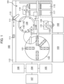
- Fig. 1 is a view schematically showing an overall configuration of an automatic analyzer 100 according to Embodiment 1 of the present disclosure.
- the automatic analyzer 100 includes a pretreatment part 101 that performs pretreatment of a sample; a separation part 102 that separates a component in the sample; an analysis part 103 that analyzes the separated component; a control unit 104 that controls an operation of the entirety of the automatic analyzer 100; an input part 105 for allowing a user to input information to the device; a display part 106 for displaying information to the user; and a storage part 107 such as storage medium that stores various information relating to a control of the automatic analyzer 100.
- the control unit 104, the input part 105, the display part 106 and the storage part 107 constitute a control device for controlling an operation of the entirety of the automatic analyzer 100.
- the pretreatment part 101 includes: a transport mechanism 112 that transports a sample container 111 in which a sample that is an object to be analyzed is contained to a sample dispensing position; a reaction vessel disc 120 that is capable of holding solutions in the reaction vessels 116 at a fixed temperature by mounting the reaction vessels 116 in a plurality of opening portions 119; a reagent disc 122 that holds a plurality of reagent vessels 121 in which reagents are contained; a sample dispensing mechanism 113 that dispenses a sample to the reaction vessels 116 contained in the opening portions 119 of the reaction vessel disc 120 from the sample container 111 transported to a sample dispensing position.
- the pretreatment part 101 further includes: a reagent dispensing mechanism 123 that dispenses a reagent to the reaction vessels 116 of the reaction vessel disc 120 from the reagent vessels 121; a dispensing chip mounting rack 115 on which disposable dispensing chips 115a that are mounted on nozzles of the sample dispensing mechanism 113 and are not yet used are mounted; and a dispensing chip detachably mounting part 114 that removes the used dispensing chips 115a from the nozzles of the sample dispensing mechanism 113 and discards the used dispensing chips 115a and mounts non-used dispensing chips 115a to the nozzles.
- the pretreatment part 101 further includes: a reaction vessels mounting rack 117 on which non-used reaction vessels 116 are mounted; and a transport mechanism 118 that transports non-used dispensing chips 115a from the dispensing chip mounting rack 115 to the dispensing chip detachably mounting part 114, transports used reaction vessels 116 from the opening portions 119 of the reaction vessel disc 120 to a discard part (not illustrated in the drawing) and transports non-used reaction vessels 116 from the reaction vessel mounting rack 117 to the opening portions 119 of the reaction vessel disc 120.
- the pretreatment part 101 further includes: a magnetic separation mechanism 124 that separates magnetic beads in a solution contained in the reaction vessel 116 by a magnetic force of a magnet; an evaporation concentration mechanism 131 that evaporates and concentrates a component to be analyzed in the solution in the reaction vessel 116; a transport mechanism 132 that transports the reaction vessel 116 between the reaction vessel disc 120, the magnetic separation mechanism 124 and the evaporation concentration mechanism 131.
- the pretreatment part 101 further includes a separation-part-use dispensing mechanism 133 that dispenses a solution in the reaction vessel 116 after the evaporation and the concentration to the separation part 102.
- the separation-part-use dispensing mechanism 133 also plays a role of dispensing a liquid between a container that the magnetic separation mechanism 124 holds and a container that the evaporation concentration mechanism 131 holds.
- the reaction vessel disc 120 functions as an incubator that holds a temperature of the reaction vessels 116 disposed in the opening portions 119 at a constant temperature, and incubates the reaction vessels 116 disposed in the opening portions 119 for a fixed time.
- the separation part 102 is, for example, a liquid chromatography (LC) and includes a column or the like as a function of separating a component in a reaction solution that is dispensed by the separation-part-use dispensing mechanism 133.
- the separation part 102 separates a component in a reaction solution dispensed from the reaction vessel 116 by the separation-part-use dispensing mechanism 133, and sequentially introduces the separated component to the analysis part 103.
- LC liquid chromatography
- the analysis part 103 is, for example, a mass spectrometry (MS), and includes an electron multiplier or the like as a function of performing ionization and a mass analysis of a component introduced from the separation part 102.
- the analysis part 103 ionizes components introduced from the separation part 102 and detects a quantity of ions (that is, a quantity of components), and outputs a detection result to the control unit 104.
- the control unit 104 controls operations of the entirety of the automatic analyzer 100 such as an operation of the magnetic separation mechanism 124, an operation of the evaporation concentration mechanism 131, an operation of the separation part 102, and an operation of the analysis part 103. Further, the control unit 104 calculates a concentration value of components in a sample using a detection result (a quantity of ions) from the analysis part 103 and a calibration curve obtained in advance, stores the concentration value in the storage part 107 as an analysis result and, at the same time, displays the analysis result on the display part 106.
- a detection result a quantity of ions
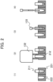
- Fig. 2 is a view explaining conventional operations of a transport mechanism and a nozzle.
- transport mechanism 132 mounts a container on the magnetic separation mechanism 124 or the evaporation concentration mechanism 131, and a nozzle of the separation-part-use dispensing mechanism 133 (for the sake of convenience, simply referred to as the nozzle 133 hereinafter) gets accesses to the container, and aspirates or discharges a liquid.
- the transport mechanism 132 and the nozzle 133 are controlled by the control unit 104.
- the magnetic separation mechanism 124 includes a first installation part 221 as a portion for installing a container (a hole for receiving the container).
- the evaporation concentration mechanism 131 includes a second installation part 222 as a portion for installing a container.
- the transport mechanism 132 accesses these installation parts, and installs the containers at the respective installation parts.
- a state is illustrated where the first container 211 is already installed at the first installation part 221 ( Fig. 2 (1)).
- any arbitrary containers are considered.
- the reaction vessel 116 is installed as the first container 211 or the second container 212.
- the transport mechanism 132 installs the second container 212 at the second installation part 222 ( Fig. 2(2) ).
- the transport mechanism 132 is, for example, configured to hold the second container 212 by clamping, to insert the second container 212 to the second installation part 222 and, thereafter, to release the second container 212.
- Such a mechanism requires a space size of a certain magnitude. Accordingly, during a period that the transport mechanism 132 accesses the first installation part 221 or the second installation part 222, the nozzle 133 can not get access to the first installation part 221 and the second installation part 222 (when the nozzle 133 intends to get access to the first installation part 221 and the second installation part 222, the transport mechanism 132 and the nozzle 133 collide with each other). Accordingly, during a period that the transport mechanism 132 installs the second container 212 at the second installation part 222, the nozzle 133 is evacuated to a position spaced apart from the first installation part 221 and the second installation part 222.
- Transport mechanism 132 is evacuated to the position spaced apart from the first installation part 221 and the second installation part 222.
- the nozzle 133 can get access to the first installation part 221 and the second installation part 222.
- the nozzle 133 accesses the first container 211 that the first installation part 221 holds (that is, introduces the nozzle 133 into the first container 211).
- the nozzle 133 aspirates a liquid stored in the first container 211 ( Fig. 2 (3)).
- the nozzle 133 accesses the second installation part 222 (that is, moves to a position above the second installation part 222).
- the nozzle 133 accesses the second container 212 that the second installation part 222 holds (that is, introduces the nozzle 133 into the second container 212).
- the nozzle 133 discharges a liquid aspirated in to the nozzle 133 to the second container 212 ( Fig. 2(4) ).
- a case is exemplified where, to prevent magnet beads used for refining a material to be measured from being introduced into the separation part 102, the first container 211 that stores a liquid containing magnetic beads is installed at the first installation part 221, and only a supernatant liquid is moved to the second container 212 installed at the second installation part 222.
- the transport mechanism 132 cannot get access to the first installation part 221 and the second installation part 222 (that is, cannot install a next container) until an operation that the nozzle 133 starts aspiration of a liquid and the liquid is discharged is completed (and until the nozzle 133 is evacuated to a position where the nozzle 133 does not collide with the transport mechanism 132).
- the restriction is imposed on an operation time chart of the automatic analyzer 100.
- the transport mechanism 132 and the nozzle 133 do not simultaneously get access to the first installation part 221 or the second installation part 222.
- conventional operation steps illustrated in Fig. 2 cause such restriction.
- the present invention particularly focuses on a state that the transport mechanism 132 has to standby from a point of time that the nozzle 133 aspirates a liquid to a point of time that the nozzle 133 discharges the liquid.
- Fig. 3 is a view explaining operations of the transport mechanism 132 and the nozzle 133 according to Embodiment 1. In the same manner as Fig. 2 , the description starts from a state where the first container 211 is already installed at the first installation part 221 ( Fig. 3(1) ).
- the nozzle 133 accesses the first installation part 221 (moves to a position above the first installation part 221) before the transport mechanism 132 installs the second container 212 at the second installation part 222.
- the nozzle 133 accesses the first container 211 that the first installation part 221 holds (the nozzle 133 being introduced into the first container 211).
- the nozzle 133 aspirates a liquid that the first container 211 contains ( Fig. 3(2) ).
- the nozzle 133 is evacuated to the position spaced apart from the first installation part 221 and the second installation part 222 ( Fig. 3 (3)). As the nozzle 133 is evacuated, the transport mechanism 132 can access the first installation part 221 and the second installation part 222.
- the transport mechanism 132 holds the second container 212 and accesses the second installation part 222 (moves to a position above the second installation part 222).
- the transport mechanism 132 installs the second container 212 at the second installation part 222 ( Fig. 3 (4)).
- Transport mechanism 132 is evacuated to the position spaced apart from the first installation part 221 and the second installation part 222.
- the nozzle 133 accesses the second installation part 222 (moves to the position above the second installation part 222).
- the nozzle 133 accesses the second container 212 that the second installation part 222 holds (introduces the nozzle 133 into the second container 212).
- the nozzle 133 discharges a liquid that is aspirated into the nozzle 133 to the second container 212 ( Fig. 3(5) ).
- Embodiment 1 According to the operations in Embodiment 1 described heretofore, during a period from a point of time that the nozzle 133 aspirates a liquid to a point of time that nozzle 133 discharges the liquid, the operation where the transport mechanism 132 installs the second container 212 exists. Accordingly, compared to the operations illustrated in Fig .2 , it is unnecessary for the transport mechanism 132 to standby from a point of time that the nozzle 133 aspirates a liquid to a point of time that the nozzle 133 discharges the liquid. That is, the restriction imposed on the operation time chart of the automatic analyzer 100 can be alleviated compared to the case illustrated in Fig. 2 .
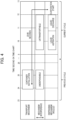
- Fig. 4 is a time chart of conventional operations explained in Fig. 2 .
- the nozzle 133 can perform neither the aspiration of a liquid nor discharging of the liquid ("container installation" and "undispensable” in Fig. 4 , the period corresponding to Fig. 2(2) ).
- the nozzle 133 aspirates a liquid from the first container 211, and discharges the liquid to the second container 212 ("liquid aspiration" and "liquid discharge” in Fig. 4 , the period corresponding to Fig. 2(3) , (4)).
- the transport mechanism 132 can transport the next container to either the first installation part 221 or the second installation part 222.
- the evaporation concentration mechanism 131 starts evaporation and concentration by reducing a pressure in the second container 212 ("evaporation start" in Fig. 4 ).
- Fig. 5 is a time chart of operations according to Embodiment 1 explained in Fig. 3 .
- the nozzle 133 Aspirates a liquid from the first container 211 ("liquid aspiration" in Fig. 5 , a period corresponding to Fig. 3(2) ), the nozzle 133 is evacuated to a position in the vicinity of a cleaning vessel, for example ("evacuation" in Fig. 5 , a period corresponding to Fig. 3 (3)).
- the transport mechanism 132 installs the second container 212 ("container installation" in Fig. 5 , a period corresponding to Fig. 3(4) ).
- the nozzle 133 discharges a liquid to the second container 212 ("liquid discharge" in Fig.5 , a period corresponding to Fig. 3(5) ).
- the evaporation concentration mechanism 131 starts evaporation and concentration by reducing a pressure in the second container 212 ("evaporation start" in Fig.5 ).
- Embodiment 1 the reason that the restriction imposed on the operation time chart is alleviated can be considered as follows.
- the operation that the transport mechanism 132 installs the second container 212 at the second installation part 222 exists. That is, a period during which the transport mechanism 132 is untransportable and the period during which the nozzle 133 is undispensable can be finely divided compared to the conventional operations.
- the operation non-allowable period and the operation allowable period can be arranged on the time chart more flexibly than the prior art and hence, the restriction imposed on the time chart can be more easily optimized than the prior art.
- the alleviation of the restriction according to Embodiment 1 is brought about by such a reason.
- the aspiration exhibits the stable behavior.
- the longer a liquid aspiration time by the nozzle 133 the longer a time for evacuating the transport mechanism 132 becomes. Accordingly, the restriction imposed on the time chart is increased.
- the aspiration time can be prolonged without increasing the restriction imposed on the time chart of the transport mechanism 132.
- Embodiment 1 it is also considered to realize the operation steps substantially equal to the operation steps illustrated in Fig. 3 by using a mechanism that moves the first installation part 221 and the second installation part 222 (example: a mechanism substantially equal to the reaction vessel disc 120).
- a mechanism that moves the first installation part 221 and the second installation part 222 (example: a mechanism substantially equal to the reaction vessel disc 120).
- the mechanism for moving the installation parts is liable to become large-sized and hence, the use of such a mechanism is not desirable from a viewpoint of a size and a cost of the device.
- Embodiment 1 is advantageous also from a viewpoint of the size of the device.
- the first installation unit 221 and the second installation unit 222 are disposed outside the reaction vessel disc 120, the container placed on the reaction vessel disc 120 is installed at the first installation part 221 or the second installation part 222, and the operations illustrated in Fig. 3 are performed or, alternately, the operations illustrated in Fig. 3 are performed on the first installation part 221 and the second installation part 222 and, thereafter, the container is moved with respect to the reaction vessel disc 120.
- the transport mechanism 132 and the nozzle 133 are configured not to be able to simultaneously access the first installation part 221 or the second installation part 222. That is, after the nozzle 133 aspirates a liquid from the first container 211 and before the nozzle 133 discharges the liquid to the second container 212, the transport mechanism 132 installs the second container 212 at the second installation part 222.
- the transport mechanism 132 performs many operations for transporting the reaction vessel 116 between the plurality of mechanisms on the device so that the large restriction is imposed on the preparation of a time chart, a time interval necessary for evacuating the transport mechanism 132 from the position at which the transport mechanism 132 collides with the nozzle 133 can be shortened. That is, the restriction imposed on the operation time chart of the automatic analyzer 100 can be alleviated.
- the automatic analyzer 100 when the transport mechanism 132 accesses the first installation part 221 or the second installation part 222, the nozzle 133 is evacuated, and when the nozzle 133 accesses the first installation part 221 or the second installation part 222, the transport mechanism 132 is evacuated. Accordingly, it is possible to alleviate the restriction imposed on the operation time chart of the automatic analyzer 100 while avoiding the collision between the transport mechanism 132 and the nozzle 133.
- a period from a point of time that the transport mechanism 132 installs the second container 212 to a point of time that the evaporation concentration mechanism 131 starts the evaporation and concentration can be shortened compared to a conventional operation.
- the evaporation concentration mechanism 131 is used for both heating and evaporation, when a long time elapses without advancing the step while leaving the second container 212 in an installed state on the evaporation concentration mechanism 131, the second container 212 is heated more than necessary.
- Embodiment 1 has an advantageous effect that such a heating time can be shortened.
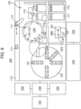
- Fig. 6 is an overall configuration diagram of an automatic analyzer 100 according to Embodiment 2 of the present disclosure.
- the example is described where the first installation part 221 and the second installation part 222 are formed as a part of the magnetic separation mechanism 124 or the evaporation concentration mechanism 131.
- Places where the first installation part 221 and the second installation part 222 are arranged are not limited to such places, and such places may be any other desired places where the respective containers for transferring a liquid by the nozzle between the first container 211 and the second container 212 are installed.
- the first installation part 221 and the second installation part 222 can be used as a temporary installation position 600 where the container is temporarily installed for transferring a liquid.
- the first installation part 221 and the second installation part 222 may be arranged at any other suitable places.
- the first installation part 221 and the second installation part 222 are provided at the temporary installation position 600.
- the temporary installation position 600 is an empty space for temporarily provisionally installing the container. For example, in a case where a liquid stored in the first container 211 is diluted, a small amount of liquid is transferred to the second container 212, and as a space for adding a diluting solution by a diluting solution discharge nozzle (not illustrated in the drawing), the temporary installation position 600 can be also used.
- An operation time chart with respect to the first installation part 221 and the second installation part 222 is equal to the corresponding operation time chart in Embodiment 1.
- Fig. 7A is an overall configuration diagram of an automatic analyzer 100 according to Embodiment 3 of this disclosure.
- Embodiment 1 the operation example in the case where a liquid is dispensed between the magnetic separation mechanism 124 and the evaporation concentration mechanism 131 is described.
- the places where the first installation part 221 and the second installation part 222 are arranged are not limited to such places.
- the magnetic separation mechanism 124 has the first installation part 221
- the temporary installation position 600 has the second installation part 222
- an operation substantially equal to the operation in Embodiment 1 may be performed between the first installation part 221 and the second installation part 222.
- Fig. 7B is another configuration diagram of an automatic analyzer 100 according to Embodiment 3. As illustrated in Fig. 7B , the temporary installation position 600 has the first installation part 221, the evaporation concentration mechanism 131 has the second installation part 222, and an operation substantially equal to the operation in Embodiment 1 may be performed between the first installation part 221 and the second installation part 222.
- Embodiments are described in detail for describing this disclosure in an easily understandable manner. However, it is not always necessary for this disclosure to include all constitutions. Further, a part of one Embodiment may be replaced with the configuration of another Embodiment. Further, the configuration of another Embodiment may be added to the configuration of one Embodiment. Further, with respect to a part of the configuration of each Embodiment, the addition, the deletion or the replacement of a part of the configuration of other Embodiment may be performed.
- the input part 105 and the display part 106 are illustrated as separate bodies. However, in place of such a configuration, for example, as in the case of a touch panel type monitor, the input part 105 and the display part 106 may be formed as an integral body.
- the transport mechanism 132 may transport articles other than the first container 211 or the second container 212 during the "untransportable" period on the time chart. With such an operation, an operation efficiency of the transport mechanism 132 can be increased.
- the reaction vessel 116 is exemplified as examples of the first container 211 and the second container 212 and, further the nozzle 133 is exemplified as the mechanism for dispensing a liquid to the first container 211 and the second container 212.
- the containers and the dispensing mechanism are not limited to these containers and dispensing mechanism, and a technique relating to this disclosure is applicable to other arbitrary containers and dispensing mechanism.
- the description is made with respect to the case where the evaporation concentration mechanism 131 concentrates a liquid by reducing a pressure in the container.
- a technique for concentrating the liquid is not limited to such a case, and the liquid may be concentrated by any other suitable technique. It must be noted that, the technique according to this disclosure is also applicable to such a case.
- control unit 104 may be constituted of a hardware such as a circuit device to which functions of the control unit 104 are implemented.
- control unit 104 may be constituted by allowing an arithmetic operation device (for example, central processing unit: CPU) to execute a software in which such functions are implemented.
- CPU central processing unit
Landscapes
- Immunology (AREA)
- Health & Medical Sciences (AREA)
- Chemical & Material Sciences (AREA)
- Life Sciences & Earth Sciences (AREA)
- General Health & Medical Sciences (AREA)
- Biochemistry (AREA)
- Physics & Mathematics (AREA)
- General Physics & Mathematics (AREA)
- Analytical Chemistry (AREA)
- Pathology (AREA)
- Chemical Kinetics & Catalysis (AREA)
- Hydrology & Water Resources (AREA)
- Automatic Analysis And Handling Materials Therefor (AREA)
Abstract
Description
- The present disclosure relates to an automatic analyzer.
- An automatic analyzer for a liquid sample analyzes a specific component contained in a specimen such as a blood or urine, for example. The automatic analyzer aspirates a liquid such as a sample or a reagent from a container by a nozzle, or discharges the sample or the reagent to the container. The automatic analyzer further includes a transport mechanism for moving the container to an installation place.
-
Patent literature 1 discloses a technique for transporting a liquid container mounted on a rack to a nozzle (see paragraph 0006).Patent literature 2 discloses a technique for discharging a specimen or a reagent to reaction vessels arranged on a reaction disc (see paragraph 0038). -
- Patent Literature 1:
Japanese Unexamined Patent Application Publication No. 2011-102735 - Patent Literature 2:
Japanese Unexamined Patent Application Publication No. 2014-206381 - In the prior art disclosed in
patent literatures - Depending on shapes and sizes of the transport mechanism and the nozzle, there may be a case where only either one of the transport mechanism and the nozzle is accessible to the installation place for the container. For example, a case where the installation place is fixed, and unless either one of the transport mechanism and the nozzle is evacuated from the installation place, the other is not accessible to the installation place, corresponds to such a case. With such a configuration, an operation of the transport mechanism or the nozzle is restricted and hence, an operation time chart of the automatic analyzer is also restricted due to such a restriction.
- The present disclosure is made in view of the above-mentioned drawback, and it is an object of the present invention to alleviate the restriction imposed on an operation time chart of an automatic analyzer brought about by allowing a transport mechanism and a nozzle to be accessible to the same installation place.
- The present disclosure provides a control method for controlling an automatic analyzer, in which the automatic analyzer is configured not to allow a transport mechanism of a container and a nozzle to be simultaneously accessible to an installation part of the container, and after the nozzle aspirates a liquid from a first container installed at the installation part and before the nozzle discharges the liquid to a second container installed at the installation part, the transport mechanism installs the second container in the installation part.
- According to the control method for controlling an automatic analyzer of the present disclosure, it is possible to alleviate the restriction imposed on an operation time chart of the automatic analyzer brought about by allowing the transport mechanism and the nozzle to access the same installation place. Other technical features, other advantageous effects, other configurations of the present disclosure will become apparent by referencing the following detailed description.
-
-
Fig. 1 is a view schematically showing an overall configuration of anautomatic analyzer 100 according toEmbodiment 1. -
Fig. 2 is a view explaining conventional operations of a transport mechanism and a nozzle. -
Fig. 3 is a view explaining operations of atransport mechanism 132 and anozzle 133 according toEmbodiment 1. -
Fig. 4 is a time chart of conventional operations explained inFig. 2 . -
Fig. 5 is a time chart of operations according to Embodiment 1 explained inFig. 3 . -
Fig. 6 is an overall configuration diagram of anautomatic analyzer 100 according toEmbodiment 2. -
Fig. 7A is an overall configuration diagram of anautomatic analyzer 100 according toEmbodiment 3. -
Fig. 7B is another configuration diagram of anautomatic analyzer 100 according toEmbodiment 3. -
Fig. 1 is a view schematically showing an overall configuration of anautomatic analyzer 100 according toEmbodiment 1 of the present disclosure. InFig. 1 , theautomatic analyzer 100 includes apretreatment part 101 that performs pretreatment of a sample; aseparation part 102 that separates a component in the sample; ananalysis part 103 that analyzes the separated component; acontrol unit 104 that controls an operation of the entirety of theautomatic analyzer 100; aninput part 105 for allowing a user to input information to the device; adisplay part 106 for displaying information to the user; and astorage part 107 such as storage medium that stores various information relating to a control of theautomatic analyzer 100. - The
control unit 104, theinput part 105, thedisplay part 106 and thestorage part 107 constitute a control device for controlling an operation of the entirety of theautomatic analyzer 100. - The
pretreatment part 101 includes: atransport mechanism 112 that transports asample container 111 in which a sample that is an object to be analyzed is contained to a sample dispensing position; areaction vessel disc 120 that is capable of holding solutions in thereaction vessels 116 at a fixed temperature by mounting thereaction vessels 116 in a plurality ofopening portions 119; areagent disc 122 that holds a plurality ofreagent vessels 121 in which reagents are contained; asample dispensing mechanism 113 that dispenses a sample to thereaction vessels 116 contained in theopening portions 119 of thereaction vessel disc 120 from thesample container 111 transported to a sample dispensing position. - The
pretreatment part 101 further includes: areagent dispensing mechanism 123 that dispenses a reagent to thereaction vessels 116 of thereaction vessel disc 120 from thereagent vessels 121; a dispensingchip mounting rack 115 on which disposable dispensingchips 115a that are mounted on nozzles of thesample dispensing mechanism 113 and are not yet used are mounted; and a dispensing chip detachably mountingpart 114 that removes the used dispensingchips 115a from the nozzles of thesample dispensing mechanism 113 and discards the used dispensingchips 115a and mounts non-used dispensingchips 115a to the nozzles. - The
pretreatment part 101 further includes: a reactionvessels mounting rack 117 on whichnon-used reaction vessels 116 are mounted; and atransport mechanism 118 that transports non-used dispensingchips 115a from the dispensingchip mounting rack 115 to the dispensing chip detachably mountingpart 114, transports usedreaction vessels 116 from theopening portions 119 of thereaction vessel disc 120 to a discard part (not illustrated in the drawing) and transportsnon-used reaction vessels 116 from the reactionvessel mounting rack 117 to theopening portions 119 of thereaction vessel disc 120. - The
pretreatment part 101 further includes: amagnetic separation mechanism 124 that separates magnetic beads in a solution contained in thereaction vessel 116 by a magnetic force of a magnet; anevaporation concentration mechanism 131 that evaporates and concentrates a component to be analyzed in the solution in thereaction vessel 116; atransport mechanism 132 that transports thereaction vessel 116 between thereaction vessel disc 120, themagnetic separation mechanism 124 and theevaporation concentration mechanism 131. - The
pretreatment part 101 further includes a separation-part-use dispensing mechanism 133 that dispenses a solution in thereaction vessel 116 after the evaporation and the concentration to theseparation part 102. As described later, the separation-part-use dispensing mechanism 133 also plays a role of dispensing a liquid between a container that themagnetic separation mechanism 124 holds and a container that theevaporation concentration mechanism 131 holds. - The
reaction vessel disc 120 functions as an incubator that holds a temperature of thereaction vessels 116 disposed in theopening portions 119 at a constant temperature, and incubates thereaction vessels 116 disposed in theopening portions 119 for a fixed time. - The
separation part 102 is, for example, a liquid chromatography (LC) and includes a column or the like as a function of separating a component in a reaction solution that is dispensed by the separation-part-use dispensing mechanism 133. Theseparation part 102 separates a component in a reaction solution dispensed from thereaction vessel 116 by the separation-part-use dispensing mechanism 133, and sequentially introduces the separated component to theanalysis part 103. - The
analysis part 103 is, for example, a mass spectrometry (MS), and includes an electron multiplier or the like as a function of performing ionization and a mass analysis of a component introduced from theseparation part 102. Theanalysis part 103 ionizes components introduced from theseparation part 102 and detects a quantity of ions (that is, a quantity of components), and outputs a detection result to thecontrol unit 104. - The
control unit 104 controls operations of the entirety of theautomatic analyzer 100 such as an operation of themagnetic separation mechanism 124, an operation of theevaporation concentration mechanism 131, an operation of theseparation part 102, and an operation of theanalysis part 103. Further, thecontrol unit 104 calculates a concentration value of components in a sample using a detection result (a quantity of ions) from theanalysis part 103 and a calibration curve obtained in advance, stores the concentration value in thestorage part 107 as an analysis result and, at the same time, displays the analysis result on thedisplay part 106. -
Fig. 2 is a view explaining conventional operations of a transport mechanism and a nozzle. In thisEmbodiment 1, assume a scene wheretransport mechanism 132 mounts a container on themagnetic separation mechanism 124 or theevaporation concentration mechanism 131, and a nozzle of the separation-part-use dispensing mechanism 133 (for the sake of convenience, simply referred to as thenozzle 133 hereinafter) gets accesses to the container, and aspirates or discharges a liquid. Thetransport mechanism 132 and thenozzle 133 are controlled by thecontrol unit 104. - In the example illustrated in
Fig. 2 , themagnetic separation mechanism 124 includes afirst installation part 221 as a portion for installing a container (a hole for receiving the container). In the same manner, theevaporation concentration mechanism 131 includes asecond installation part 222 as a portion for installing a container. Thetransport mechanism 132 accesses these installation parts, and installs the containers at the respective installation parts. InFig. 2 , a state is illustrated where thefirst container 211 is already installed at the first installation part 221 (Fig. 2 (1)). As thefirst container 211 and asecond container 212 described later, any arbitrary containers are considered. For example, it is considered that thereaction vessel 116 is installed as thefirst container 211 or thesecond container 212. - The
transport mechanism 132 installs thesecond container 212 at the second installation part 222 (Fig. 2(2) ). Thetransport mechanism 132 is, for example, configured to hold thesecond container 212 by clamping, to insert thesecond container 212 to thesecond installation part 222 and, thereafter, to release thesecond container 212. Such a mechanism requires a space size of a certain magnitude. Accordingly, during a period that thetransport mechanism 132 accesses thefirst installation part 221 or thesecond installation part 222, thenozzle 133 can not get access to thefirst installation part 221 and the second installation part 222 (when thenozzle 133 intends to get access to thefirst installation part 221 and thesecond installation part 222, thetransport mechanism 132 and thenozzle 133 collide with each other). Accordingly, during a period that thetransport mechanism 132 installs thesecond container 212 at thesecond installation part 222, thenozzle 133 is evacuated to a position spaced apart from thefirst installation part 221 and thesecond installation part 222. -
Transport mechanism 132 is evacuated to the position spaced apart from thefirst installation part 221 and thesecond installation part 222. When thetransport mechanism 132 is evacuated, thenozzle 133 can get access to thefirst installation part 221 and thesecond installation part 222. Thenozzle 133 accesses thefirst container 211 that thefirst installation part 221 holds (that is, introduces thenozzle 133 into the first container 211). Thenozzle 133 aspirates a liquid stored in the first container 211 (Fig. 2 (3)). - The
nozzle 133 accesses the second installation part 222 (that is, moves to a position above the second installation part 222). Thenozzle 133 accesses thesecond container 212 that thesecond installation part 222 holds (that is, introduces thenozzle 133 into the second container 212). Thenozzle 133 discharges a liquid aspirated in to thenozzle 133 to the second container 212 (Fig. 2(4) ). - As an example of a case where it is necessary to perform the above-mentioned aspirating and discharging operation, a case is exemplified where, to prevent magnet beads used for refining a material to be measured from being introduced into the
separation part 102, thefirst container 211 that stores a liquid containing magnetic beads is installed at thefirst installation part 221, and only a supernatant liquid is moved to thesecond container 212 installed at thesecond installation part 222. - According to the conventional operations described above, the
transport mechanism 132 cannot get access to thefirst installation part 221 and the second installation part 222 (that is, cannot install a next container) until an operation that thenozzle 133 starts aspiration of a liquid and the liquid is discharged is completed (and until thenozzle 133 is evacuated to a position where thenozzle 133 does not collide with the transport mechanism 132). With such an operation, the restriction is imposed on an operation time chart of theautomatic analyzer 100. - As one of factors that cause such restriction, it is considered that the
transport mechanism 132 and thenozzle 133 do not simultaneously get access to thefirst installation part 221 or thesecond installation part 222. In addition to such a factor, conventional operation steps illustrated inFig. 2 cause such restriction. InEmbodiment 1, the present invention particularly focuses on a state that thetransport mechanism 132 has to standby from a point of time that thenozzle 133 aspirates a liquid to a point of time that thenozzle 133 discharges the liquid. -
Fig. 3 is a view explaining operations of thetransport mechanism 132 and thenozzle 133 according toEmbodiment 1. In the same manner asFig. 2 , the description starts from a state where thefirst container 211 is already installed at the first installation part 221 (Fig. 3(1) ). - The
nozzle 133 accesses the first installation part 221 (moves to a position above the first installation part 221) before thetransport mechanism 132 installs thesecond container 212 at thesecond installation part 222. Thenozzle 133 accesses thefirst container 211 that thefirst installation part 221 holds (thenozzle 133 being introduced into the first container 211). Thenozzle 133 aspirates a liquid that thefirst container 211 contains (Fig. 3(2) ). - The
nozzle 133 is evacuated to the position spaced apart from thefirst installation part 221 and the second installation part 222 (Fig. 3 (3)). As thenozzle 133 is evacuated, thetransport mechanism 132 can access thefirst installation part 221 and thesecond installation part 222. - The
transport mechanism 132 holds thesecond container 212 and accesses the second installation part 222 (moves to a position above the second installation part 222). Thetransport mechanism 132 installs thesecond container 212 at the second installation part 222 (Fig. 3 (4)). -
Transport mechanism 132 is evacuated to the position spaced apart from thefirst installation part 221 and thesecond installation part 222. Thenozzle 133 accesses the second installation part 222 (moves to the position above the second installation part 222). Thenozzle 133 accesses thesecond container 212 that thesecond installation part 222 holds (introduces thenozzle 133 into the second container 212). Thenozzle 133 discharges a liquid that is aspirated into thenozzle 133 to the second container 212 (Fig. 3(5) ). - According to the operations in
Embodiment 1 described heretofore, during a period from a point of time that thenozzle 133 aspirates a liquid to a point of time thatnozzle 133 discharges the liquid, the operation where thetransport mechanism 132 installs thesecond container 212 exists. Accordingly, compared to the operations illustrated inFig .2 , it is unnecessary for thetransport mechanism 132 to standby from a point of time that thenozzle 133 aspirates a liquid to a point of time that thenozzle 133 discharges the liquid. That is, the restriction imposed on the operation time chart of theautomatic analyzer 100 can be alleviated compared to the case illustrated inFig. 2 . -
Fig. 4 is a time chart of conventional operations explained inFig. 2 . During a period that thetransport mechanism 132 installs thesecond container 212 at thesecond installation part 222, thenozzle 133 can perform neither the aspiration of a liquid nor discharging of the liquid ("container installation" and "undispensable" inFig. 4 , the period corresponding toFig. 2(2) ). After thetransport mechanism 132 is evacuated, thenozzle 133 aspirates a liquid from thefirst container 211, and discharges the liquid to the second container 212 ("liquid aspiration" and "liquid discharge" inFig. 4 , the period corresponding toFig. 2(3) , (4)). When the liquid discharge is completed and thenozzle 133 is evacuated, thetransport mechanism 132 can transport the next container to either thefirst installation part 221 or thesecond installation part 222. - After the
nozzle 133 discharges a liquid, theevaporation concentration mechanism 131 starts evaporation and concentration by reducing a pressure in the second container 212 ("evaporation start" inFig. 4 ). -
Fig. 5 is a time chart of operations according toEmbodiment 1 explained inFig. 3 . After thenozzle 133 aspirates a liquid from the first container 211 ("liquid aspiration" inFig. 5 , a period corresponding toFig. 3(2) ), thenozzle 133 is evacuated to a position in the vicinity of a cleaning vessel, for example ("evacuation" inFig. 5 , a period corresponding toFig. 3 (3)). During a period that thenozzle 133 is evacuated, thetransport mechanism 132 installs the second container 212 ("container installation" inFig. 5 , a period corresponding toFig. 3(4) ). After thetransport mechanism 132 is evacuated, thenozzle 133 discharges a liquid to the second container 212 ("liquid discharge" inFig.5 , a period corresponding toFig. 3(5) ). - After the
nozzle 133 discharges a liquid, theevaporation concentration mechanism 131 starts evaporation and concentration by reducing a pressure in the second container 212 ("evaporation start" inFig.5 ). - In
Embodiment 1, the reason that the restriction imposed on the operation time chart is alleviated can be considered as follows. InEmbodiment 1, during a period from a point of time that thenozzle 133 starts aspiration of a liquid in thefirst container 211 to a point of time that thenozzle 133 discharges the liquid to thesecond container 212, the operation that thetransport mechanism 132 installs thesecond container 212 at thesecond installation part 222 exists. That is, a period during which thetransport mechanism 132 is untransportable and the period during which thenozzle 133 is undispensable can be finely divided compared to the conventional operations. Accordingly, the operation non-allowable period and the operation allowable period can be arranged on the time chart more flexibly than the prior art and hence, the restriction imposed on the time chart can be more easily optimized than the prior art. The alleviation of the restriction according toEmbodiment 1 is brought about by such a reason. - In general, by performing the aspiration of a liquid at a low speed, the aspiration exhibits the stable behavior. In the conventional operation, the longer a liquid aspiration time by the
nozzle 133, the longer a time for evacuating thetransport mechanism 132 becomes. Accordingly, the restriction imposed on the time chart is increased. With the use ofEmbodiment 1, the aspiration time can be prolonged without increasing the restriction imposed on the time chart of thetransport mechanism 132. - In
Embodiment 1, it is also considered to realize the operation steps substantially equal to the operation steps illustrated inFig. 3 by using a mechanism that moves thefirst installation part 221 and the second installation part 222 (example: a mechanism substantially equal to the reaction vessel disc 120). In this case, however, the mechanism for moving the installation parts is liable to become large-sized and hence, the use of such a mechanism is not desirable from a viewpoint of a size and a cost of the device.Embodiment 1 is advantageous also from a viewpoint of the size of the device. In other words, thefirst installation unit 221 and thesecond installation unit 222 are disposed outside thereaction vessel disc 120, the container placed on thereaction vessel disc 120 is installed at thefirst installation part 221 or thesecond installation part 222, and the operations illustrated inFig. 3 are performed or, alternately, the operations illustrated inFig. 3 are performed on thefirst installation part 221 and thesecond installation part 222 and, thereafter, the container is moved with respect to thereaction vessel disc 120. - In the
automatic analyzer 100 according toEmbodiment 1, thetransport mechanism 132 and thenozzle 133 are configured not to be able to simultaneously access thefirst installation part 221 or thesecond installation part 222. That is, after thenozzle 133 aspirates a liquid from thefirst container 211 and before thenozzle 133 discharges the liquid to thesecond container 212, thetransport mechanism 132 installs thesecond container 212 at thesecond installation part 222. With such a configuration, although thetransport mechanism 132 performs many operations for transporting thereaction vessel 116 between the plurality of mechanisms on the device so that the large restriction is imposed on the preparation of a time chart, a time interval necessary for evacuating thetransport mechanism 132 from the position at which thetransport mechanism 132 collides with thenozzle 133 can be shortened. That is, the restriction imposed on the operation time chart of theautomatic analyzer 100 can be alleviated. - In the
automatic analyzer 100 according toEmbodiment 1, when thetransport mechanism 132 accesses thefirst installation part 221 or thesecond installation part 222, thenozzle 133 is evacuated, and when thenozzle 133 accesses thefirst installation part 221 or thesecond installation part 222, thetransport mechanism 132 is evacuated. Accordingly, it is possible to alleviate the restriction imposed on the operation time chart of theautomatic analyzer 100 while avoiding the collision between thetransport mechanism 132 and thenozzle 133. - In the
automatic analyzer 100 according toEmbodiment 1, a period from a point of time that thetransport mechanism 132 installs thesecond container 212 to a point of time that theevaporation concentration mechanism 131 starts the evaporation and concentration can be shortened compared to a conventional operation. In a case where theevaporation concentration mechanism 131 is used for both heating and evaporation, when a long time elapses without advancing the step while leaving thesecond container 212 in an installed state on theevaporation concentration mechanism 131, thesecond container 212 is heated more than necessary.Embodiment 1 has an advantageous effect that such a heating time can be shortened. -
Fig. 6 is an overall configuration diagram of anautomatic analyzer 100 according toEmbodiment 2 of the present disclosure. InEmbodiment 1, the example is described where thefirst installation part 221 and thesecond installation part 222 are formed as a part of themagnetic separation mechanism 124 or theevaporation concentration mechanism 131. Places where thefirst installation part 221 and thesecond installation part 222 are arranged are not limited to such places, and such places may be any other desired places where the respective containers for transferring a liquid by the nozzle between thefirst container 211 and thesecond container 212 are installed. For example, as atemporary installation position 600 where the container is temporarily installed for transferring a liquid, thefirst installation part 221 and thesecond installation part 222 can be used. Thefirst installation part 221 and thesecond installation part 222 may be arranged at any other suitable places. - In the example illustrated in
Fig. 6 , thefirst installation part 221 and thesecond installation part 222 are provided at thetemporary installation position 600. Thetemporary installation position 600 is an empty space for temporarily provisionally installing the container. For example, in a case where a liquid stored in thefirst container 211 is diluted, a small amount of liquid is transferred to thesecond container 212, and as a space for adding a diluting solution by a diluting solution discharge nozzle (not illustrated in the drawing), thetemporary installation position 600 can be also used. An operation time chart with respect to thefirst installation part 221 and thesecond installation part 222 is equal to the corresponding operation time chart inEmbodiment 1. -
Fig. 7A is an overall configuration diagram of anautomatic analyzer 100 according toEmbodiment 3 of this disclosure. InEmbodiment 1, the operation example in the case where a liquid is dispensed between themagnetic separation mechanism 124 and theevaporation concentration mechanism 131 is described. However, the places where thefirst installation part 221 and thesecond installation part 222 are arranged are not limited to such places. For example, as illustrated inFig. 7A , themagnetic separation mechanism 124 has thefirst installation part 221, thetemporary installation position 600 has thesecond installation part 222, and an operation substantially equal to the operation inEmbodiment 1 may be performed between thefirst installation part 221 and thesecond installation part 222. -
Fig. 7B is another configuration diagram of anautomatic analyzer 100 according toEmbodiment 3. As illustrated inFig. 7B , thetemporary installation position 600 has thefirst installation part 221, theevaporation concentration mechanism 131 has thesecond installation part 222, and an operation substantially equal to the operation inEmbodiment 1 may be performed between thefirst installation part 221 and thesecond installation part 222. - This disclosure is not limited to the above-mentioned Embodiments, and includes various modifications. For example, the above-mentioned Embodiments are described in detail for describing this disclosure in an easily understandable manner. However, it is not always necessary for this disclosure to include all constitutions. Further, a part of one Embodiment may be replaced with the configuration of another Embodiment. Further, the configuration of another Embodiment may be added to the configuration of one Embodiment. Further, with respect to a part of the configuration of each Embodiment, the addition, the deletion or the replacement of a part of the configuration of other Embodiment may be performed.
- In
Embodiment 1, theinput part 105 and thedisplay part 106 are illustrated as separate bodies. However, in place of such a configuration, for example, as in the case of a touch panel type monitor, theinput part 105 and thedisplay part 106 may be formed as an integral body. - In the above-mentioned Embodiments, the
transport mechanism 132 may transport articles other than thefirst container 211 or thesecond container 212 during the "untransportable" period on the time chart. With such an operation, an operation efficiency of thetransport mechanism 132 can be increased. - In the above-mentioned Embodiments, the
reaction vessel 116 is exemplified as examples of thefirst container 211 and thesecond container 212 and, further thenozzle 133 is exemplified as the mechanism for dispensing a liquid to thefirst container 211 and thesecond container 212. It must be noted that the containers and the dispensing mechanism are not limited to these containers and dispensing mechanism, and a technique relating to this disclosure is applicable to other arbitrary containers and dispensing mechanism. - In the above-mentioned Embodiments, the description is made with respect to the case where the
evaporation concentration mechanism 131 concentrates a liquid by reducing a pressure in the container. However, a technique for concentrating the liquid is not limited to such a case, and the liquid may be concentrated by any other suitable technique. It must be noted that, the technique according to this disclosure is also applicable to such a case. - In the above-mentioned Embodiment, the control unit 104 (controller) may be constituted of a hardware such as a circuit device to which functions of the
control unit 104 are implemented. Alternatively, thecontrol unit 104 may be constituted by allowing an arithmetic operation device (for example, central processing unit: CPU) to execute a software in which such functions are implemented. - It must be noted that, in the above-mentioned Embodiment, numerical examples illustrated in
Fig. 4 andFig. 5 are one example, and this disclosure is not limited by these numerical values. -
- 100: automatic analyzer
- 104: control unit
- 124: magnetic separation mechanism
- 131: evaporation concentration mechanism
- 132: transport mechanism
- 133: nozzle
- 211: first container
- 212: second container
- 221: first installation part
- 222: second installation part
Claims (9)
- A control method for controlling an automatic analyzer that analyzes a sample,
wherein:the automatic analyzer hasa nozzle that aspirates or discharges a liquid,a first installation part where a first container for storing the liquid is installed,a second installation part where a second container for storing the liquid is installed, anda transport mechanism for transporting the first container and the second container;both the nozzle and the transport mechanism are accessible to each of the first container installed at the first installation part and the second container installed at the second installation part;the first installation part and the second installation part are respectively placed at positions where the transport mechanism and the nozzle are in contact with each other when the nozzle accesses the first container installed at the first installation part while the transport mechanism accesses the second container installed at the second installation part; andthe control method includes the steps of:aspirating the liquid by the nozzle from the first container installed at the first installation part;installing the second container at the second installation part by the transport mechanism after the nozzle aspirates the liquid from the first container; anddischarging the liquid by the nozzle to the second container. - A control method according to Claim 1, further including a step of:evacuating the transport mechanism from the second installation part before the nozzle discharges the liquid to the second container after the transport mechanism installs the second container at the second installation part, whereinat the step of discharging the liquid, the nozzle is moved to a position where the nozzle can discharge the liquid to the second container by moving the nozzle to a space created at the step of evacuating the transport mechanism.
- A control method according to Claim 1, further including a step of:evacuating the nozzle from the first installation part before the transport mechanism installs the second container at the second installation part after the nozzle aspirates the liquid from the first container, whereinat the step of installing the second container at the second installation part, the transport mechanism is moved to a position where the transport mechanism can install the second container at the second installation part after the transport mechanism and the nozzle are in the state of not being in contact with each other by evacuating the nozzle.
- A control method according to Claim 3, wherein:at the step of evacuating the nozzle from the first installation part, the nozzle is evacuated from the first installation part while the liquid aspirated from the first container by the nozzle is retained in the nozzle; andat the step of discharging the liquid to the second container, the liquid retained in the nozzle is discharged to the second container.
- A control method according to Claim 1, wherein:the automatic analyzer further has a reaction disc over which a reaction vessel containing the sample is mounted when the sample is reacted;the first installation part and the second installation part are placed outside the reaction disc; andthe control method further has a step of mounting the first container or the second container as the reaction vessel over the reaction disc, or moving the first container or the second container to the first installation part or the second installation part from the reaction disc, by moving the first container between the first installation part and the reaction disc or moving the second container between the second installation part and the reaction disc.
- A control method according to Claim 1, wherein:the automatic analyzer further has a magnetic separation device for separating magnetic particles contained in a liquid in a container;the first installation part is configured as a place where the first container is installed for the magnetic separation device; andthe step of aspiration is applied to the first container installed in the magnetic separation device.
- A control method according to Claim 1, wherein:the automatic analyzer further has an evaporation concentration device for concentrating a liquid by evaporating the liquid stored in a container;the second installation part is configured as a place where the second container is installed for the evaporation concentration device; andthe step of installing the second container and the step of discharge are applied to the second container installed in the evaporation concentration device.
- A control method according to Claim 7, further including a step of:
evaporating and concentrating the liquid in the second container after the liquid is discharged to the second container. - An automatic analyzer for analyzing a sample, the automatic analyzer including a controller for controlling the automatic analyzer by implementing a control method according to Claim 1.
Applications Claiming Priority (2)
| Application Number | Priority Date | Filing Date | Title |
|---|---|---|---|
| JP2021173792 | 2021-10-25 | ||
| PCT/JP2022/037885 WO2023074351A1 (en) | 2021-10-25 | 2022-10-11 | Automatic analysis device control method and automatic analysis device |
Publications (2)
| Publication Number | Publication Date |
|---|---|
| EP4425184A1 true EP4425184A1 (en) | 2024-09-04 |
| EP4425184A4 EP4425184A4 (en) | 2025-10-29 |
Family
ID=86157902
Family Applications (1)
| Application Number | Title | Priority Date | Filing Date |
|---|---|---|---|
| EP22886680.2A Pending EP4425184A4 (en) | 2021-10-25 | 2022-10-11 | CONTROL METHOD FOR AUTOMATIC ANALYSIS DEVICE AND AUTOMATIC ANALYSIS DEVICE |
Country Status (5)
| Country | Link |
|---|---|
| US (1) | US20240402205A1 (en) |
| EP (1) | EP4425184A4 (en) |
| JP (1) | JP7688149B2 (en) |
| CN (1) | CN118103713A (en) |
| WO (1) | WO2023074351A1 (en) |
Family Cites Families (10)
| Publication number | Priority date | Publication date | Assignee | Title |
|---|---|---|---|---|
| US6190617B1 (en) * | 1992-03-27 | 2001-02-20 | Abbott Laboratories | Sample container segment assembly |
| JP4102739B2 (en) * | 2003-11-25 | 2008-06-18 | 株式会社日立ハイテクノロジーズ | Automatic analyzer |
| JP2008180538A (en) * | 2007-01-23 | 2008-08-07 | Olympus Corp | Analyzer |
| JP4940032B2 (en) * | 2007-06-29 | 2012-05-30 | 株式会社東芝 | Automatic analyzer and its reagent storage |
| JP5324400B2 (en) * | 2009-11-10 | 2013-10-23 | 日立アロカメディカル株式会社 | Dispensing device |
| JP6153759B2 (en) * | 2013-04-10 | 2017-06-28 | 株式会社日立ハイテクノロジーズ | Automatic analyzer |
| CN111279202B (en) * | 2018-02-28 | 2023-09-12 | 株式会社日立高新技术 | automatic analysis device |
| US12529709B2 (en) * | 2019-07-04 | 2026-01-20 | Hitachi High-Tech Corporation | Automatic analysis device |
| CN112014582B (en) * | 2020-08-31 | 2024-05-03 | 成都艾科斯伦医疗科技有限公司 | A fully automatic coagulation analyzer scheduling method |
| JP2022118402A (en) * | 2021-02-02 | 2022-08-15 | キヤノンメディカルシステムズ株式会社 | Standard sample container and automatic analyzer |
-
2022
- 2022-10-11 WO PCT/JP2022/037885 patent/WO2023074351A1/en not_active Ceased
- 2022-10-11 JP JP2023556286A patent/JP7688149B2/en active Active
- 2022-10-11 EP EP22886680.2A patent/EP4425184A4/en active Pending
- 2022-10-11 US US18/699,866 patent/US20240402205A1/en active Pending
- 2022-10-11 CN CN202280068350.4A patent/CN118103713A/en active Pending
Also Published As
| Publication number | Publication date |
|---|---|
| JP7688149B2 (en) | 2025-06-03 |
| US20240402205A1 (en) | 2024-12-05 |
| JPWO2023074351A1 (en) | 2023-05-04 |
| WO2023074351A1 (en) | 2023-05-04 |
| CN118103713A (en) | 2024-05-28 |
| EP4425184A4 (en) | 2025-10-29 |
Similar Documents
| Publication | Publication Date | Title |
|---|---|---|
| JP3931150B2 (en) | Automatic analyzer | |
| JP7402875B2 (en) | automatic analyzer | |
| EP3185016B1 (en) | System layout for an automated system for sample preparation and analysis | |
| US11060081B2 (en) | Specimen pretreatment apparatus, specimen pretreatment cartridge, and specimen pretreatment method | |
| JP7232841B2 (en) | automatic analyzer | |
| KR20240004692A (en) | Sample pooling systems and methods for high-throughput analysis | |
| EP3855179B1 (en) | Analysis device having liquid chromatograph, and liquid chromatograph analysis method | |
| EP3812774A1 (en) | Automatic analysis device | |
| US20240402205A1 (en) | Automatic analysis device control method and automatic analysis device | |
| EP3336554A1 (en) | Pretreatment device, and analysis system provided with same | |
| EP3190407A1 (en) | Preprocessing device and analysis system provided with same | |
| JP6332449B2 (en) | Pretreatment device | |
| JP5978039B2 (en) | Automatic analyzer | |
| EP4439068A1 (en) | Automatic analysis device | |
| WO2023281940A1 (en) | Automatic analysis device control method and automatic analysis device | |
| EP4737904A1 (en) | Sample analysis system | |
| EP4697006A1 (en) | Evaporation concentration mechanism and automatic analysis device including same | |
| WO2026105393A1 (en) | Storage box | |
| JP4607677B2 (en) | Automatic analyzer container transport mechanism | |
| WO2025263417A1 (en) | Processing device and automatic analysis device | |
| WO2025243688A1 (en) | Processing device | |
| US20230333130A1 (en) | System and Method for Disposing of a Reaction Vessel of a Mass Spectrometry System | |
| JPWO2024062751A5 (en) | automatic analyzer |
Legal Events
| Date | Code | Title | Description |
|---|---|---|---|
| STAA | Information on the status of an ep patent application or granted ep patent |
Free format text: STATUS: THE INTERNATIONAL PUBLICATION HAS BEEN MADE |
|
| PUAI | Public reference made under article 153(3) epc to a published international application that has entered the european phase |
Free format text: ORIGINAL CODE: 0009012 |
|
| STAA | Information on the status of an ep patent application or granted ep patent |
Free format text: STATUS: REQUEST FOR EXAMINATION WAS MADE |
|
| 17P | Request for examination filed |
Effective date: 20240408 |
|
| AK | Designated contracting states |
Kind code of ref document: A1 Designated state(s): AL AT BE BG CH CY CZ DE DK EE ES FI FR GB GR HR HU IE IS IT LI LT LU LV MC ME MK MT NL NO PL PT RO RS SE SI SK SM TR |
|
| DAV | Request for validation of the european patent (deleted) | ||
| DAX | Request for extension of the european patent (deleted) | ||
| A4 | Supplementary search report drawn up and despatched |
Effective date: 20250929 |
|
| RIC1 | Information provided on ipc code assigned before grant |
Ipc: G01N 35/00 20060101AFI20250923BHEP Ipc: G01N 35/02 20060101ALI20250923BHEP Ipc: G01N 35/04 20060101ALI20250923BHEP Ipc: G01N 35/10 20060101ALI20250923BHEP Ipc: G01N 1/10 20060101ALI20250923BHEP Ipc: G01N 30/04 20060101ALI20250923BHEP |