EP4425089A1 - Barrel assembly for a firearm - Google Patents
Barrel assembly for a firearm Download PDFInfo
- Publication number
- EP4425089A1 EP4425089A1 EP24160427.1A EP24160427A EP4425089A1 EP 4425089 A1 EP4425089 A1 EP 4425089A1 EP 24160427 A EP24160427 A EP 24160427A EP 4425089 A1 EP4425089 A1 EP 4425089A1
- Authority
- EP
- European Patent Office
- Prior art keywords
- clamping
- barrel
- clamping jaw
- abutment
- lever
- Prior art date
- Legal status (The legal status is an assumption and is not a legal conclusion. Google has not performed a legal analysis and makes no representation as to the accuracy of the status listed.)
- Granted
Links
Images







Classifications
-
- F—MECHANICAL ENGINEERING; LIGHTING; HEATING; WEAPONS; BLASTING
- F41—WEAPONS
- F41A—FUNCTIONAL FEATURES OR DETAILS COMMON TO BOTH SMALLARMS AND ORDNANCE, e.g. CANNONS; MOUNTINGS FOR SMALLARMS OR ORDNANCE
- F41A21/00—Barrels; Gun tubes; Muzzle attachments; Barrel mounting means
- F41A21/48—Barrel mounting means, e.g. releasable mountings for replaceable barrels
- F41A21/487—Barrel mounting means, e.g. releasable mountings for replaceable barrels using friction, e.g. by clamping a barrel surface
-
- F—MECHANICAL ENGINEERING; LIGHTING; HEATING; WEAPONS; BLASTING
- F41—WEAPONS
- F41A—FUNCTIONAL FEATURES OR DETAILS COMMON TO BOTH SMALLARMS AND ORDNANCE, e.g. CANNONS; MOUNTINGS FOR SMALLARMS OR ORDNANCE
- F41A3/00—Breech mechanisms, e.g. locks
- F41A3/58—Breakdown breech mechanisms, e.g. for shotguns
-
- F—MECHANICAL ENGINEERING; LIGHTING; HEATING; WEAPONS; BLASTING
- F41—WEAPONS
- F41C—SMALLARMS, e.g. PISTOLS, RIFLES; ACCESSORIES THEREFOR
- F41C23/00—Butts; Butt plates; Stocks
- F41C23/16—Forestocks; Handgrips; Hand guards
Definitions
- the invention relates to a barrel assembly for a firearm, in particular for a carbine, as well as to a firearm comprising the barrel assembly.
- the firearm according to the invention may preferably be a carbine, but it may also be a semiautomatic or automatic rifle, a machine gun, a repeating rifle, a shotgun, some other rifle, a submachine gun, a pistol etc.
- Firearms are guns that can be carried and used by one person.
- DE202012101602U1 discloses in this respect a dismantlable firearm, with a barrel frictionally held in a receiver by means of a clamping device, wherein the clamping device has two clamping jaws which can be clamped in opposite directions and lie against the barrel, and also a clamping element, with which the clamping jaws are pressed against the barrel.
- the clamping device disclosed in DE202012101602U1 requires a greater amount of space and is also insufficiently user-friendly.
- the object of the present invention was to provide an improved barrel assembly, as well as an improved firearm.
- the invention concerns a barrel assembly for a firearm, in particular for a carbine.
- the barrel assembly comprises:
- the barrel assembly according to the invention has the advantage that the clamping device or the eccentric clamp can be of a simple and space-saving construction. As a result, improved operation of the eccentric clamp is made possible. Furthermore, this measure allows the eccentric clamp to be formed on the firearm while taking up as little space as possible.
- first clamping jaw and the second clamping jaw are at least in some sections separated from one another by a slit, wherein the slit separates the clearance and the clamping lever mount from one another.
- clamping lever mount of the first clamping jaw reaches beyond the weapon median plane into the second clamping jaw.
- a clamping lever bolt is formed on the clamping lever mount and that a clamping lever hole is formed in the clamping lever, wherein the clamping lever bolt reaches into the clamping lever hole. This measure allows the clamping lever to be easily mounted on the clamping lever mount.
- clamping lever is secured on the clamping lever bolt by means of a clamping-lever securing ring.
- the clamping device has a base, wherein the first clamping jaw and the second clamping jaw are formed as one part with the base, wherein the slit extends from the base over a longitudinal extent of the first clamping jaw and the second clamping jaw.
- a clamping of the clamping jaws can be achieved as a result of the attachment of the first clamping jaw and the second clamping jaw to the base element and as a result of the formation of the slit with an elastic deformation of the base element or of the clamping jaws.
- the clamping device has on an underside, between the base and the first clamping jaw and/or between the base and the second clamping jaw, a transverse slit, which adjoins the slit.
- the first clamping jaw is only coupled to the base in the region of a first side wall and/or that the second clamping jaw is only coupled to the base in the region of a second side wall. This measure can achieve the effect that the first clamping jaw and the second clamping jaw can more easily be clamped in relation to one another by means of the eccentric clamp.
- the abutment is kept at an abutment distance from a weapon median plane, and the pivot axis is kept at a clamping-lever mount distance from the weapon median plane, wherein the abutment distance extends into a first side of the weapon median plane and the clamping-lever mount distance extends into a second side of the weapon median plane,
- the abutment is kept at an abutment distance from a weapon median plane, and the pivot axis is kept at a clamping-lever mount distance from the weapon median plane, or the pivot axis lies in the weapon median plane, wherein the abutment distance extends into a first side of the weapon median plane and the clamping-lever mount distance likewise extends into a first side of the weapon median plane, but the clamping-lever mount distance is less than the abutment distance.
- the embodiment with an abutment component has the advantage that it can be easily produced. It may be provided in particular that the abutment component is fastened on an underside of the second clamping jaw and the first clamping jaw protrudes downwards.
- the embodiment with the cover plate has the advantage that such a construction can be easily produced and in addition can be mechanically robust. It may be provided in particular that a clamping device formed in such a way takes the form of a cast part, which can be worked by machining.
- cover plate is formed on an underside of the second clamping jaw and the first clamping jaw protrudes downwards.
- a butting block on which the abutment is formed is mounted in the cover plate. It may be provided in particular that the butting block is formed by a hardened component.
- a first abutment fastening is formed on a first longitudinal side of the clearance and, at a distance therefrom in the axial direction of the barrel bore axis, a second abutment fastening is formed on a second longitudinal side of the clearance, wherein the abutment component is coupled to the first abutment fastening and to the second abutment fastening, wherein the abutment component spans the clearance.
- the first abutment fastening takes the form of a first bolt and the second abutment fastening takes the form of a second bolt, wherein the first bolt and the second bolt are mounted on the second clamping jaw, wherein the abutment component has a first hole for receiving the first bolt and a second hole for receiving the second bolt.
- an abutment fastening constructed in such a way can be of a simple construction. Consequently, the abutment can be easily installed and easily uninstalled again.
- the first hole takes the form of a slot which extends in a transverse direction in relation to the barrel bore axis and that the second hole takes the form of a slot which extends parallel to the longitudinal extent of a barrel bore axis.
- an adjusting-screw threaded hole that leads into the first hole is formed in the abutment component, wherein there is an adjusting screw screwed into the adjusting-screw threaded hole, wherein the adjusting screw lies against the first bolt directly or by means of an interposed transmission element and wherein the adjusting screw is designed for adjusting the position of the abutment.
- the second hole takes the form of a slot which extends in a transverse direction in relation to the barrel bore axis and that the first hole takes the form of a slot which extends parallel to the longitudinal extent of a barrel bore axis and that an adjusting-screw threaded hole that leads into the second hole is formed in the abutment component, wherein there is an adjusting screw screwed into the adjusting-screw threaded hole, wherein the adjusting screw lies against the second bolt directly or by means of an interposed transmission element and wherein the adjusting screw is designed for adjusting the position of the abutment.
- a securing hole that leads into the adjusting-screw threaded hole is formed in the abutment component, while held in the securing hole there is a securing screw which clamps the adjusting screw.
- the adjusting screw and the securing screw may be formed as worm screws.
- a first securing ring is arranged on the first bolt and that a second securing ring is arranged on the second bolt, wherein the first securing ring and the second securing ring serve for securing the abutment component.
- the abutment component has first material properties and the first clamping jaw and/or the second clamping jaw has second material properties, wherein the first material properties are different from the second material properties. It may be provided here that the abutment component is hardened, in particular that the abutment has a higher hardness than the second clamping jaw. It may also be provided that the abutment has a higher modulus of elasticity than the second clamping jaw.
- the pivot axis is arranged vertically, in particular that the clamping lever mount is arranged on an underside of the clamping device.
- This has the advantage that the clamping lever can be moved between its clamping position and its releasing position by lateral pulling. This is particularly ergonomic, and the clamping lever can consequently be easily operated by a user.
- the pivot axis is arranged horizontally.
- the first clamping jaw and the second clamping jaw may be arranged vertically one above the other, and the clamping may take place in a vertical direction.
- the clamping lever has a longitudinal extent, wherein the clamping lever in the clamping position is aligned parallel to the barrel bore axis.
- the clamping lever can be pivoted out of its clamping position into its releasing position by means of a user exerting lateral pulling.
- first clamping jaw is delimited by a first outer delimiting plane and the second clamping jaw is delimited by a second outer delimiting plane, wherein the pivot axis is arranged within the first outer delimiting plane and the second outer delimiting plane.
- the first outer delimiting plane and the second outer delimiting plane may be formed by external surfaces of the clamping device.
- first outer delimiting plane and the second outer delimiting plane are aligned vertically.
- a receiver in particular an upper receiver is formed, wherein the clamping device is fastened on the upper receiver by means of fastening means. This measure allows easy connection between the upper receiver and the clamping device to be achieved.
- the receiver at least partially takes the form of a hollow profile and is consequently of an O-shaped form.
- the receiver would not be assembled from an upper receiver and a lower receiver but would be formed as one part.
- a barrel extension is formed, wherein a barrel mount, which serves for the mounting of the first barrel end of the barrel, is formed in the barrel extension and wherein the barrel is coupled to the barrel extension and wherein the first clamping jaw and the second clamping jaw of the clamping device act on the barrel extension.
- the barrel is not directly clamped by the clamping device, but the barrel extension in which the barrel is mounted is clamped. It may be provided here in particular that the barrel is inserted in the barrel extension by a form-fitting connection.
- the barrel has the structural features of the barrel extension.
- the barrel and the barrel extension can consequently be formed as one part, as integral components.
- the first clamping jaw and the second clamping jaw can act directly on the barrel.
- the barrel extension embodiment it may be provided that the barrel is mounted directly in the clamping device, or is held by it.
- a first prism guide is formed on a first side of the barrel extension and a second prism guide is formed on a second side of the barrel extension, wherein a first counter guide, corresponding to the first prism guide, is formed on the first clamping jaw and wherein a second counter guide, corresponding to the second prism guide, is formed on the second clamping jaw.
- the barrel extension has a barrel extension slit running in the longitudinal extent of the barrel bore axis, wherein the barrel extension is deformable, so that the barrel mount can be pressed in a radial direction against the first barrel end.
- the weapon median plane is formed in the middle of the barrel extension slit.
- a pivot bearing is formed on the clamping device, wherein the pivot bearing serves for the pivotable attachment to a receiver.
- the pivot bearing may in particular take the form of a sliding bearing.
- the pivot bearing may be arranged on an underside of the clamping device. It may also be provided that the pivot bearing is formed on the base of the clamping device. It may be provided in particular that the receiver is formed as a lower receiver.
- a handguard is formed, wherein the handguard is removably coupled to the clamping device by displacement in the axial direction of the barrel bore axis.
- a securing element is arranged in the handguard, wherein the securing element is formed in such a way that the handguard can only be pushed onto the clamping device when the clamping lever is in the clamping position and that, in the assembled state of the handguard and the clamping device, the clamping lever is secured in the clamping position by means of the securing element.
- the clamping lever has a locking lug, wherein the locking lug is formed in such a way that the clamping lever with the inserted barrel and barrel extension can only be transferred into the clamping position when the barrel extension is correctly inserted in the clamping device.
- an axial stop which serves for the axial positioning of the barrel extension in relation to the clamping device, is formed on the barrel extension. It may be provided in particular that the barrel extension butts against the clamping device in the axial direction by means of the axial stop, and is consequently positioned in relation to the barrel extension in the axial direction.
- the barrel assembly is formed according to one of the specific embodiments above.
- first clamping jaw and the second clamping jaw are separated from one another by the slit.
- the slit may form a constant distance between the first clamping jaw and the second clamping jaw in the longitudinal extent of the barrel bore axis.
- the clearance of the second clamping jaw may also be referred to as a depression. Seen in the longitudinal extent of the barrel bore axis, an elevation may be formed before the depression and after the depression. In particular, the clearance may have the effect that the second clamping jaw is shaped in a way similar to the hump of a camel.
- the first clamping jaw may be shaped in a way which complements the second clamping jaw, wherein the clamping lever mount may take the form of an elevation which can reach into the clearance of the second clamping jaw.
- first clamping jaw and the second clamping jaw partially overlap.
- the overlapping is in this case characterized in that the first clamping jaw and the second clamping jaw are separated from one another by the slit, wherein, seen over the longitudinal extent of the barrel bore axis, the position of the slit is displaced transversely to the barrel bore axis.
- This specific embodiment can be seen well in Fig. 10 .
- clamping or displacing of the first clamping jaw and the second clamping jaw in relation to one another can be achieved as a result of the elasticity of the material of the clamping device.
- first clamping jaw and the second clamping jaw do not have any direct rigid connection to one another, but are formed as independent components which are arranged on the upper receiver part, the elasticity of the material of the upper receiver part can be used for the clamping and/or displacing of the first clamping jaw and the second clamping jaw in relation to one another.
- the deformation of components within the limits of their elasticity can be used here to achieve a spring-elastic recovery of the first clamping jaw and the second clamping jaw, so that, when there is an opening of the eccentric clamp, the first clamping jaw and the second clamping jaw are moved away from one another.
- the clamping device has a sleeve segment, wherein the sleeve segment surrounds the barrel in some sections in the form of a sleeve, wherein the first clamping jaw and the second clamping jaw are coupled as one part to the sleeve segment.
- the definition that the sleeve segment surrounds the barrel in some sections in the form of a sleeve may mean in a first embodiment variant that the sleeve segment lies directly against the barrel.
- the definition that the sleeve segment surrounds the barrel in some sections in the form of a sleeve may also mean that a further component is arranged between the sleeve segment and the barrel. This further component may be for example the barrel extension.
- the enclosing of the barrel or a barrel extension may allow increased precision of the firearm to be achieved.
- the sleeve segment together with the first clamping jaw and the second clamping jaw form an inner clamping surface, wherein the inner clamping surface substantially takes the form of a cylinder segment, wherein the first clamping jaw and the second clamping jaw are designed for deforming the inner clamping surface.
- That the inner clamping surface substantially takes the form of a cylinder segment means that forms departing from the geometrically ideal form of a cylinder segment, which are caused for example by the deforming of the inner clamping surface, can likewise be seen as being in the form of a cylinder segment. It may be provided in particular that the inner clamping surface in the unloaded state has the form of a cylinder segment.
- the production of the inner clamping surface may be achieved by corresponding production processes, such as for instance milling out, grinding, honing or broaching. In particular, in this way production of the clamping device can be more efficiently achieved..
- a weight saving can be achieved in comparison with other embodiments.
- the installation space can be reduced.
- a force transmission component is formed, wherein the force transmission component is mounted on the sleeve segment and is supported on the upper receiver. This is accompanied by the advantage that by this measure the forces can be transmitted from the barrel to the upper receiver.
- the force transmission component has a force transmission projection, wherein the force transmission projection is supported on the barrel extension.
- the forces can be transmitted directly from the barrel extension to the upper receiver.
- the sleeve segment may serve here as a carrier for the force transmission component.
- formed in the barrel extension is a shaped recess, which matches the force transmission projection. This allows a longitudinal stop and consequently a linear positioning of the barrel extension in relation to the clamping device to be achieved. Furthermore, by this measure it can be achieved that the barrel extension is prevented from twisting in relation to the clamping device.
- the firearm may have a weapon median plane, passing through the barrel bore axis and oriented vertically. It may be provided in particular that the weapon median plane forms a plane of symmetry for at least parts of the firearm.
- the terms "front/forward”, “rear/rearward”, “above”, “below”, “vertical/vertically” and so on are used in the common form and with reference to the subject matter in the position of use, in which the axis of the barrel is aligned horizontally and the weapon median plane is aligned vertically.
- the firearm 1 has a receiver or receiver part.
- the receiver may for example comprise an upper receiver 8 and/or a lower receiver 9.
- the present invention is described by way of example on the basis of a receiver with an upper receiver 8 and a lower receiver 9.
- the barrel assembly 2 according to the invention is not restricted to this embodiment with a separate upper receiver 8 and lower receiver 9, but may for example also be formed on a one-part receiver. In a further alternative, the barrel assembly may be formed on another receiver part.
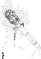
- Fig. 3 shows a first exemplary embodiment of a barrel assembly 2 in a perspective view.
- the barrel assembly 2 is attached to the lower receiver 9 by means of a turning bolt that is not shown. It may also be provided that the turning bolt is removable, whereby the barrel assembly 2 can be removed from the lower receiver 9.
- the first exemplary embodiment of the barrel assembly 2 is shown in the same view as in Fig. 3 , with the same reference numerals or component designations as in the preceding Figures 1 to 3 being used again for the same parts.
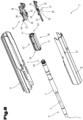
- Fig. 6 the barrel assembly 2 is shown in an exploded view.
- the handguard 10 and the upper receiver 8 are not shown in Figures 4 and 5 .
- the clamping device 17 is shown in two different positions.
- the clamping device 17 has a first clamping jaw 19 and a second clamping jaw 20. It may be provided in particular that the first clamping jaw 19 is arranged on a first side of the barrel 3, in particular on a first side of a weapon median plane 72. It may also be provided that the second clamping jaw 20 is arranged on a second side of the barrel 3, in particular on a second side of the weapon median plane 72.
- first clamping jaw 19 and the second clamping jaw 20 can be clamped in relation to one another by means of an eccentric clamp 21. It may be provided in particular that an eccentric clamp 21 is formed for the clamping of the first clamping jaw 19 and the second clamping jaw 20.
- the eccentric clamp 21 may have a clamping lever 22.
- the clamping lever 22 may be arranged on the first clamping jaw 19 pivotably with respect to a pivot axis 23 between a clamping position 24, as shown in Fig. 4 , and a releasing position 25, as shown in Fig. 5 .
- pivot axis 23 is arranged vertically. It may also be provided that a butting surface 26, which serves for the butting against an abutment 27, is arranged on the clamping lever 22.
- the clamping lever mount 29 may serve here for the mounting of the clamping lever 22.
- clamping lever mount 29 of the first clamping jaw 19 reaches beyond the weapon median plane 72 into the second clamping jaw 20.
- a slit 50 by means of which the first clamping jaw 19 and the second clamping jaw 20 are separated from one another, is formed at least in some sections.
- a clamping lever bolt 30 is formed on the clamping lever mount 29 and that a clamping lever hole 31 is formed in the clamping lever 22.
- the clamping lever hole 31 may serve for the fastening of the clamping lever 22 on the clamping lever bolt 30.
- a clamping-lever securing ring 32 which serves for securing the clamping lever 22 on the clamping lever bolt 30, is formed.
- the clamping-lever securing ring 32 may be mounted on the clamping lever bolt 30, in particular in a groove provided for it.
- the clamping lever hole 31 is cylindrically formed and that the pivot axis 23 forms a cylinder centre axis of the clamping lever hole 31.
- the pivot axis 23 can consequently form at the same time the centre axis of the clamping lever bolt 30.
- a loose fit is formed between the clamping lever bolt 30 and the clamping lever hole 31.
- the clamping lever bolt 30 and the clamping lever hole 31 can consequently form a sliding bearing. Because of small relative speeds and/or small relative movements, such a sliding bearing can also manage without sliding bearing materials and also manage without lubrication.
- the steel surfaces of the clamping lever bolt 30 and of the clamping lever hole 31 may slide on one another.
- a sliding bearing bush or a sliding bearing surface is arranged between the clamping lever bolt 30 and the clamping lever hole 31. Incorporating the clamping lever hole 31 at the clamping lever bolt 30 allows the clamping lever 22 to be arranged on the clamping lever mount 29 pivotably about the pivot axis 23.
- the abutment 27 is formed on a cover plate 35, wherein the cover plate 35 is formed on the second clamping jaw 20.
- the cover plate 35 may be formed in one piece with the second clamping jaw 20. It may be provided in particular that a butting block 49, on which the abutment 27 is formed, is incorporated in the cover plate 35.
- the cover plate 35 spans the clearance 28, wherein the clamping lever mount 29 is arranged closer to the second clamping jaw 20 than the cover plate 35.
- first clamping jaw 19 is delimited by a first outer delimiting plane 33 and that the second clamping jaw 20 is delimited by a second outer delimiting plane 34.
- the first outer delimiting plane 33 and the second outer delimiting plane 34 may be formed here by external surfaces of the clamping device. It may be provided in particular that the first outer delimiting plane 33 and the second outer delimiting plane 34 are formed by the surfaces that serve for the mounting of the upper receiver 8 or against which the upper receiver 8 butts.
- shaped elements 36 which serve for the form-fitting mounting of the upper receiver 8, are arranged on the clamping device 17.
- the shaped elements 36 may project with respect to the first outer delimiting plane 33 and the second outer delimiting plane 34. Threaded holes may also be formed in the region of the shaped elements 36 or between the shaped elements 36. By means of fastening means, which can be received in the threaded holes, the upper receiver 8 can consequently be fastened on the clamping device 17.
- pivot axis 23 and the abutment 27 are arranged between the first outer delimiting plane 33 and the second outer delimiting plane 34.
- This provides a particularly space-saving construction, whereby the firearm 1 can have good functionality.
- a securing element 37 is arranged on the handguard 10 not depicted in Fig. 4 .
- the securing element 37 may be mounted or fastened in the handguard 10 for example by means of fastening means. It may be provided in particular that the securing element 37 is mounted on an inner side of the handguard 10. In the assembled state of the firearm 1, the securing element 37 can serve for securing the clamping lever 22 in the clamping position 24.
- butting surface 26 is formed eccentrically in relation to the pivot axis 23.
- the butting of the butting surface 26 against the abutment 27 can achieve the effect that the clamping lever 22 is supported on the abutment 27.
- the distance between the first clamping jaw 19 and the second clamping jaw 20 can be increased. This can be achieved by utilizing the elasticity of the clamping device 17 or of the upper receiver 8.
- a pivoting of the clamping lever 22 from the releasing position 25 into the clamping position 24 allows the distance from one another of the first clamping jaw 19 and the second clamping jaw 20 to be reduced. This can be achieved by the butting surface 26 being at a differing distance from the pivot axis 23 over the pivoting angle of the clamping lever 22.
- the clamping lever 22 may butt against the securing element 37, so that the clamping lever 22 is secured in its clamping position 24 against turning into its releasing position 25.
- the securing element 37 may additionally serve the purpose that, when the clamping lever 22 is not completely pivoted into its clamping position 24, axial pushing of the handguard 10 onto the barrel 3 is not possible. This can be achieved by the securing element 37 that is arranged in the handguard 10 butting against the clamping lever 22, and in this way blocking the pushing-on.
- a barrel extension 38 in which the barrel 3 is mounted, is formed between the clamping device 17 and the barrel 3. It may be provided in particular that a barrel mount 39, in which the first barrel end 5 of the barrel 3 may be mounted, is formed in the barrel extension 38.
- barrel lugs 40 which serve for axially securing the barrel 3 in the barrel extension 38, are formed at the first barrel end 5.
- the barrel 3 may also be secured in the barrel extension 38 by additional securing elements.
- barrel locking lugs 41 by means of which the breech block unit 12 can be locked in an axially secured manner in the barrel extension 38, are formed in the barrel extension 38.
- first prism guide 43 is formed on the first side 42 of the barrel extension 38 and that a second prism guide 45 is formed on a second side 44 of the barrel extension 38.
- the first prism guide 43 may correspond to a first counter guide 46 arranged in the first clamping jaw 19.
- the second prism guide 45 may correspond to a second counter guide 47 arranged in the second clamping jaw 20. It may be provided in particular that the first prism guide 43 and the second prism guide 45 are formed as a linear guide, by which the barrel 3 can be pushed into the barrel extension 38 in the axial direction of the barrel bore axis 4.
- the barrel extension 38 has a barrel extension slit 48.
- the barrel extension slit 48 may be arranged on an underside of the barrel extension 38. It may be provided in particular that the barrel extension slit 48 extends over the complete longitudinal extent of the barrel extension 38, so that the barrel extension 38 can be deformed by means of the first clamping jaw 19 and the second clamping jaw 20, and consequently the barrel mount 39 of the barrel extension 38 can be pressed against the barrel 3 in order to be able to establish a frictional connection between the barrel 3 and the barrel mount 39.
- the functionality of the barrel extension 38 is formed directly in the barrel 3 and that the barrel extension 38 is not an independent component but is formed in one piece with the barrel 3. Consequently, the barrel locking lugs 41 may be formed directly in the barrel 3. Furthermore, the first clamping jaw 19 and the second clamping jaw 20 may lie directly against the barrel 3, so that the barrel 3 is clamped directly by the clamping device 17.
- the barrel assembly 2 according to the invention is not restricted to the firearm 1 described, with a barrel 3 and with a barrel extension 38 and a locked breech block, such as for example a breech with rotating bolt, but can also be readily transferred by a person skilled in the art to a firearm 1 with a different type of breech block, such as for example a blowback action, delayed blowback action, roller locking system etc., and the correspondingly designed barrel 3.
- FIG. 7 the first exemplary embodiment of the barrel assembly 2 is shown in a further perspective view, with a depicted securing element 37, with the same reference numerals or component designations as in the preceding Figures 1 to 6 being used again for the same parts.
- reference numerals or component designations as in the preceding Figures 1 to 6 being used again for the same parts.
- a locking lug 51 is formed on the clamping lever 22.
- the locking lug 51 may be formed in such a way that the clamping lever 22 can only be transferred into the clamping position 24 when the barrel extension 38 has been pushed far enough into the clamping device 17 in the axial direction.
- a locking lug counterpart 52 is formed on the barrel extension 38.
- the locking lug 51 may interact in a form-fitting manner with the locking lug counterpart 52.
- Fig. 8 shows the barrel assembly 2 together with the upper receiver 8 and the handguard 10 in a sectional representation according to the sectional line VIII - VIII from Fig. 7 , with the same reference numerals or component designations as in the preceding Figures 1 to 7 being used again for the same parts. In order to avoid unnecessary repetitions, reference is made to the detailed description in the preceding Figures 1 to 7 .
- the upper receiver 8 spans the clamping device 17 in a U-shaped manner. It may be provided here in particular that the upper receiver 8 has a first leg 53, a second leg 54 and an upper-receiver base 55.
- the first clamping jaw 19 may be fastened on the first leg 53 of the upper receiver 8.
- the second clamping jaw 20 may be fastened on the second leg 54 of the upper receiver 8. It may be provided in particular that the clamping jaws 19, 20 are respectively screwed to the legs 53, 54 of the upper receiver 8 by means of fastening means in the form of screws.
- the abutment 27 is arranged at an abutment distance 56 from the weapon median plane 72. It may also be provided that the pivot axis 23 is arranged at a clamping-lever mount distance 57 from the weapon median plane 72.
- the abutment distance 56 and the clamping-lever mount distance 57 are measured here as a horizontal distance.
- the pivot axis 23 may lie between the second outer delimiting plane 34 and the barrel bore axis 4.
- the abutment 27 may lie between the first outer delimiting plane 33 and the barrel bore axis 4.
- the abutment 27 may be arranged on a first side of the weapon median plane 72 and the pivot axis 23 may be arranged on a second side of the weapon median plane 72.
- abutment 27 is arranged on its own abutment component 58, which is coupled to the second clamping jaw 20.
- a first abutment fastening 60 is formed on a first longitudinal side 59 of the clearance 28. It may also be provided that a second abutment fastening 62 is formed on a second longitudinal side 61 of the clearance 28.
- the first abutment fastening 60 may comprise a first bolt 63.
- the second abutment fastening 62 may comprise a second bolt 64.
- in the abutment component 58 there is formed a first hole 65 and there is formed a second hole 66.
- the first hole 65 may be incorporated in the first bolt 63.
- the second hole 66 may be incorporated in the second bolt 64.
- a first securing ring 67 which is arranged on the first bolt 63 in a corresponding groove and serves for securing the abutment component 58, is formed. It may also be provided that a second securing ring 68, which is arranged in a groove on the second bolt 64 and serves for securing the abutment component 58, is formed.
- the clamping device 17 is formed as one part, wherein the first clamping jaw 19 and the second clamping jaw 20 are coupled to one another by means of a base 69. It may also be provided that the slit 50 is formed between the first clamping jaw 19 and the second clamping jaw 20. It may additionally be provided that a transverse slit 70, which extends between the first clamping jaw 19 and/or the second clamping jaw 20 and the base 69, is formed. The transverse slit 70 may adjoin the slit 50 in a T-shaped form.
- an axial stop 71 which serves for the axial positioning of the barrel extension 38 in relation to the clamping device 17, is formed on the barrel extension 38. It may be provided in particular that the barrel extension 38 butts against the clamping device 17 in the axial direction by means of the axial stop 71, and is consequently positioned in relation to the barrel extension 38 in the axial direction.
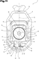
- Fig. 11 shows the second exemplary embodiment of the barrel assembly 2 together with the upper receiver 8 and the handguard 10 in a sectional representation analogous to Fig. 8 , with the same reference numerals or component designations as in the preceding Figures 1 to 10 being used again for the same parts. In order to avoid unnecessary repetitions, reference is made to the detailed description in the preceding Figures 1 to 10 .
- the barrel 3 may be inserted into the barrel extension 38, if these are two different components.
- the barrel 3 already has the features of the barrel extension 38 or that the barrel 3 and the barrel extension 38 are already connected to one another securely and acting as one part.
- the barrel 3 together with the barrel extension 38 may be pushed in between the first clamping jaw 19 and the second clamping jaw 20 of the clamping device 17, wherein the first prism guide 43 and the second prism guide 45 can serve for guiding the barrel 3 and/or the barrel extension 38.
- the locking lever 22 is in its releasing position 25, in order to make it possible for the barrel to be inserted.
- the barrel 3 can be pushed into the clamping device 17 until the axial stop 71 of the barrel extension 38 butts against the clamping device 17, and consequently the axial position of the barrel 3 is defined.
- the clamping lever 22 may be pivoted about the pivot axis 23 from the releasing position 25 into the clamping position 24.
- the butting surface 26 of the clamping lever 22 thereby slides on the abutment 27.
- the fact that the butting surface 26 is arranged eccentrically in relation to the pivot axis 23 has the effect that a displacement of the pivot axis 23 can be achieved by the pivoting.
- the construction according to the invention of the first clamping jaw 19 and the second clamping jaw 20 has the effect that the first clamping jaw 19 and the second clamping jaw 20 are in this case pulled towards one another, whereby the barrel 3 and/or the barrel extension 38 are clamped between the first clamping jaw 19 and the second clamping jaw 20.
- the clamping lever 22 can only be pivoted when the barrel 3 and/or the barrel extension 38 are correctly positioned, so that the locking lug 51 arranged on the clamping lever 22 along with the locking lug counterpart 52 can be displaced in one another.
- the handguard 10 can be pushed onto the firearm 1, wherein the securing element 37 in the handguard 10 can secure the clamping lever 22 in a form-fitting manner against opening.
- Removal of the barrel 3 can be performed in the reverse sequence.
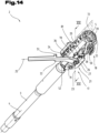
- Figures 12 to 16 show the third exemplary embodiment of the barrel assembly 2, with the same reference numerals or component designations as in the preceding Figures 1 to 11 being used again for the same parts. In order to avoid unnecessary repetitions, reference is made to the detailed description in the preceding Figures 1 to 11 .
- the third exemplary embodiment of the barrel assembly 2 is described on the basis of joint consideration of Figures 12 to 16 .
- the handguard 10 and the upper receiver 8 are not shown in Figures 12 to 16 .
- the clamping device 17 has a first clamping jaw 19 and a second clamping jaw 20. It may be provided in particular that the first clamping jaw 19 is arranged on a first side of the barrel 3, in particular on a first side of a weapon median plane 72. It may also be provided that the second clamping jaw 20 is arranged on a second side of the barrel 3, in particular on a second side of the weapon median plane 72.
- first clamping jaw 19 and the second clamping jaw 20 can be clamped in relation to one another by means of an eccentric clamp 21. It may be provided in particular that an eccentric clamp 21 is formed for the clamping of the first clamping jaw 19 and the second clamping jaw 20.
- the eccentric clamp 21 may have a clamping lever 22.
- the clamping lever 22 may be arranged on the first clamping jaw 19 pivotably with respect to a pivot axis 23 between a clamping position 24, as shown in Fig. 13 , and a releasing position 25, as shown in Fig. 14 .
- pivot axis 23 is arranged vertically. It may also be provided that a butting surface 26, which serves for the butting against an abutment 27, is arranged on the clamping lever 22.
- a slit 50 by means of which the first clamping jaw 19 and the second clamping jaw 20 are separated from one another, is formed at least in some sections. In the exemplary embodiment shown, the slit 50 extends over the complete length of the clamping device 17.
- first clamping jaw 19 is delimited by a first outer delimiting plane 33 and that the second clamping jaw 20 is delimited by a second outer delimiting plane 34.
- the first outer delimiting plane 33 and the second outer delimiting plane 34 may be formed here by external surfaces of the clamping device 17. It may be provided in particular that the first outer delimiting plane 33 and the second outer delimiting plane 34 are formed by the surfaces that serve for the mounting of the upper receiver 8 or against which the upper receiver 8 butts.
- shaped elements 36 which serve for the form-fitting mounting of the upper receiver 8, are arranged on the clamping device 17.
- the shaped elements 36 may project with respect to the first outer delimiting plane 33 and the second outer delimiting plane 34. Threaded holes may also be formed in the region of the shaped elements 36 or between the shaped elements 36. By means of fastening means, which can be received in the threaded holes, the upper receiver 8 can consequently be fastened on the clamping device 17.
- the pivot axis 23 and the abutment 27 are arranged between the first outer delimiting plane 33 and the second outer delimiting plane 34. This provides a particularly space-saving construction, whereby the firearm 1 can have good functionality
- the distance between the first clamping jaw 19 and the second clamping jaw 20 can be increased. This can be achieved by utilizing the elasticity of the clamping device 17 or of the upper receiver 8.
- a pivoting of the clamping lever 22 from the releasing position 25 into the clamping position 24 allows the distance from one another of the first clamping jaw 19 and the second clamping jaw 20 to be reduced. This can be achieved by the butting surface 26 being at a differing distance from the pivot axis 23 over the pivoting angle of the clamping lever 22.
- the clamping device 17 has a sleeve segment 73, wherein the first clamping jaw 19 and the second clamping jaw 20 are coupled as one part to the sleeve segment 73.
- the inner clamping surface 74 may substantially take the form of a cylinder segment, wherein the first clamping jaw 19 and the second clamping jaw 20 are designed for deforming the inner clamping surface 74.
- a barrel extension 38 in which the barrel 3 is mounted, is formed between the clamping device 17 and the barrel 3. It may be provided in particular that a barrel mount 39, in which the first barrel end 5 of the barrel 3 may be mounted, is formed in the barrel extension 38.
- barrel lugs 40 which serve for axially securing the barrel 3 in the barrel extension 38, are formed at the first barrel end 5.
- the barrel 3 may also be secured in the barrel extension 38 by additional securing elements.
- barrel locking lugs 41 by means of which the breech block unit 12 can be locked in an axially secured manner in the barrel extension 38, are formed in the barrel extension 38.
- the sleeve segment 73 together with the first clamping jaw 19 and the second clamping jaw 20 enclose the barrel extension 38.
- the inner clamping surface 74 can be pressed against the barrel extension 38.
- the barrel extension 38 has a barrel extension slit 48.
- the barrel extension slit 48 may be arranged on an underside of the barrel extension 38. It may be provided in particular that the barrel extension slit 48 extends only over part of the longitudinal extent of the barrel extension 38, so that the barrel extension 38 can be deformed by means of the first clamping jaw 19 and the second clamping jaw 20, and consequently the barrel mount 39 of the barrel extension 38 can be pressed against the barrel 3 in order to be able to establish a frictional connection between the barrel 3 and the barrel mount 39.
- the barrel 3 can be clamped in the barrel mount 39 of the barrel extension 38 by means of the clamping device 17, by the barrel extension 38 being deformed at least in some sections.
- a locking lug 51 is formed on the clamping lever 22.
- the locking lug 51 may be formed in such a way that the clamping lever 22 can only be transferred into the clamping position 24 when the barrel extension 38 has been pushed far enough into the clamping device 17 in the axial direction.
- a locking lug counterpart 52 is formed on the barrel extension 38.
- the locking lug 51 may interact in a form-fitting manner with the locking lug counterpart 52.
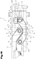
- Fig. 16 shows the barrel assembly 2 in a sectional representation according to the sectional line XVI-XVI from Fig. 13 .
- the abutment 27 is arranged at an abutment distance 56 from the weapon median plane 72. It may also be provided that the pivot axis 23 is arranged at a clamping-lever mount distance 57 from the weapon median plane 72.
- the abutment distance 56 and the clamping-lever mount distance 57 are measured here as a horizontal distance.
- the pivot axis 23 may lie between the first outer delimiting plane 33 and the barrel bore axis 4.
- the abutment 27 may likewise lie between the first outer delimiting plane 33 and the barrel bore axis 4.
- one or more material cutouts 75 are formed in the sleeve segment 73.
- the material cutouts 75 may for example take the form of holes or the form of perforations.
- the material cutouts 75 may be arranged on both sides of the sleeve segment 73.
- FIG. 16 shows a section exactly in the region of such a material cutout 75. This makes it look optically as though the sleeve segment 73 would not completely clasp the barrel extension 38.
- abutment 27 is arranged on its own abutment component 58, which is coupled to the second clamping jaw 20.
- a first abutment fastening 60 is formed on a first longitudinal side 59 of the clearance 28. It may also be provided that a second abutment fastening 62 is formed on a second longitudinal side 61 of the clearance 28.
- the first abutment fastening 60 may comprise a first bolt 63.
- the second abutment fastening 62 may comprise a second bolt 64.
- first hole 65 may be incorporated in the first bolt 63.
- second hole 66 may be incorporated in the second bolt 64. It may be provided in particular that the first hole 65 takes the form of a slot which extends in a transverse direction in relation to the barrel bore axis 4 and that the second hole 66 takes the form of a slot which extends parallel to the longitudinal extent of a barrel bore axis 4.
- an adjusting-screw threaded hole 77 that leads into the first hole 65 is formed in the abutment component 58.
- a securing hole 80 that leads into the adjusting-screw threaded hole 77 is formed in the abutment component 58, while held in the securing hole 80 there is a securing screw 81 which clamps the adjusting screw 78.
- the position of the abutment 27 can be set, whereby the clamping force of the clamping device 17 in the clamping position 24 can be set.
- the first hole 65 can thereby be positioned in a transverse direction of the firearm 1 in relation to the first bolt 63
- a first securing ring 67 which is arranged on the first bolt 63 in a corresponding groove and serves for securing the abutment component 58, is formed. It may also be provided that a second securing ring, which is arranged in a groove on the second bolt 64 and serves for securing the abutment component 58, is formed. The second securing ring is not shown in Fig. 15 for reasons of clarity.
- a clamping lever bolt 30 is formed on the clamping lever mount 29 and that a clamping lever hole 31 is formed in the clamping lever 22.
- the clamping lever hole 31 may serve for the fastening of the clamping lever 22 on the clamping lever bolt 30.
- a clamping-lever securing ring 32 which serves for securing the clamping lever 22 on the clamping lever bolt 30, is formed.
- the clamping-lever securing ring 32 may be mounted on the clamping lever bolt 30, in particular in a groove provided for it.
- the clamping lever hole 31 is cylindrically formed and that the pivot axis 23 forms a cylinder centre axis of the clamping lever hole 31.
- the pivot axis 23 can consequently form at the same time the centre axis of the clamping lever bolt 30.
- a loose fit is formed between the clamping lever bolt 30 and the clamping lever hole 31.
- the clamping lever bolt 30 and the clamping lever hole 31 can consequently form a sliding bearing. Because of small relative speeds and/or small relative movements, such a sliding bearing can also manage without sliding bearing materials and also manage without lubrication.
- the steel surfaces of the clamping lever bolt 30 and of the clamping lever hole 31 may slide on one another.
- a sliding bearing bush or a sliding bearing surface is arranged between the clamping lever bolt 30 and the clamping lever hole 31. Incorporating the clamping lever hole 31 at the clamping lever bolt 30 allows the clamping lever 22 to be arranged on the clamping lever mount 29 pivotably about the pivot axis 23.
- abutment component 58 may be applied to all other exemplary embodiments described in this document.
- a force transmission component 76 is formed.
- the force transmission component 76 may be mounted on the sleeve segment 73 and supported on the upper receiver 8. It may be provided in particular that formed on the sleeve segment 73 there is a force-transmission component mount 82, which serves for the mounting of the force transmission component 76. It may be provided in particular that the force transmission component 76 is fastened on the force-transmission component mount 82 by means of a fastening screw 83.
- the force transmission component 76 has a force transmission projection 84, wherein the force transmission projection 84 is supported on the barrel extension 38.
- formed in the barrel extension 38 is a shaped recess 85, which matches the force transmission projection 84. This allows a longitudinal stop 86 and consequently a linear positioning of the barrel extension 38 in relation to the clamping device 17 to be achieved.
- FIG 17 a further, and possibly itself independent, fourth embodiment of the barrel assembly 2 is shown, with the same reference numerals or component designations as in the preceding Figures 1 to 16 being used again for the same parts.
- the clamping device 17 here may likewise have a construction with a sleeve segment 73, such as that described in detail in Figures 12 to 16 . For reasons of simplicity, an exact repetition of this description is therefore not given.
- the clamping device 17 is formed as closed in the rear region in the form of a sleeve, wherein the first clamping jaw 19 and the second clamping jaw 20 are coupled to one another by means of a base 69. It may also be provided that the slit 50 is formed between the first clamping jaw 19 and the second clamping jaw 20. It may additionally be provided that a transverse slit 70, which extends between the first clamping jaw 19 and/or the second clamping jaw 20 and the base 69, is formed. The transverse slit 70 may adjoin the slit 50 in a T-shaped form.
- a barrel extension 38 may likewise be provided, as already described in the exemplary embodiment according to Figures 12 to 16 .
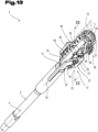
- FIGs 18 and 19 a further, and possibly itself independent, fifth embodiment of the barrel assembly 2 is shown, with the same reference numerals or component designations as in the preceding Figures 1 to 17 being used again for the same parts.
- the clamping device 17 may here likewise have a construction with a sleeve segment 73, such as that described in detail in Figures 12 to 16 . For reasons of simplicity, an exact repetition of this description is therefore not given.
- a barrel mount 39 in which the first barrel end 5 of the barrel 3 may be mounted, is formed in the clamping device 17, in particular on the base 69.
- barrel lugs 40 which serve for axially securing the barrel 3 directly in the clamping device 17, are formed at the first barrel end 5. It may also be provided that barrel locking lugs 41 are formed in the base 69 of the clamping device 17.
- the clamping of the barrel 3 may take place in the further exemplary embodiments according to Figures 12 to 19 mutatis mutandis in a way such as that described already in connection with Figures 1 to 11 .
Landscapes
- Engineering & Computer Science (AREA)
- General Engineering & Computer Science (AREA)
- Clamps And Clips (AREA)
Abstract
- a barrel (3);
- a clamping device (17) for clamping the barrel (3), wherein the clamping device (17) has a first clamping jaw (19) and a second clamping jaw (20);
- an eccentric clamp (21) with a clamping lever (22) for clamping the clamping jaws in relation to one another.
Description
- The invention relates to a barrel assembly for a firearm, in particular for a carbine, as well as to a firearm comprising the barrel assembly.
- The firearm according to the invention may preferably be a carbine, but it may also be a semiautomatic or automatic rifle, a machine gun, a repeating rifle, a shotgun, some other rifle, a submachine gun, a pistol etc. Firearms are guns that can be carried and used by one person.
- In recent years, it is increasingly being demanded by various interest groups that it must be possible to be able to uninstall and reinstall the barrel of a firearm, in particular a carbine, without great effort. This may take place for example in order to be able to use barrels of different lengths, or else to be able to use barrels of different calibres. Furthermore, this may also be helpful in order to allow improved transporting or cleaning of the firearm.
-
DE202012101602U1 discloses in this respect a dismantlable firearm, with a barrel frictionally held in a receiver by means of a clamping device, wherein the clamping device has two clamping jaws which can be clamped in opposite directions and lie against the barrel, and also a clamping element, with which the clamping jaws are pressed against the barrel. - The clamping device disclosed in
DE202012101602U1 requires a greater amount of space and is also insufficiently user-friendly. - The object of the present invention was to provide an improved barrel assembly, as well as an improved firearm.
- This object is achieved by a barrel assembly for a firearm, in particular for a carbine, as well as a firearm comprising the barrel assembly, according to the claims.
- The invention concerns a barrel assembly for a firearm, in particular for a carbine. The barrel assembly comprises:
- a barrel with a first barrel end, in the longitudinal extent of a barrel bore axis, wherein the barrel bore axis is arranged in particular in a weapon median plane;
- a clamping device for clamping the barrel, wherein the clamping device has a first clamping jaw and a second clamping jaw;
- an eccentric clamp with a clamping lever for clamping the first clamping jaw and the second clamping jaw in relation to one another, wherein the clamping lever has a pivot axis and a butting surface, wherein the butting surface is formed eccentrically in relation to the pivot axis, wherein the clamping lever is pivotable with respect to the pivot axis between a clamping position and a releasing position. A clearance is formed in the second clamping jaw, and the first clamping jaw has a clamping lever mount, wherein the clamping lever mount reaches into the clearance, in particular the first clamping jaw and the second clamping jaw partially overlap, wherein the clamping lever is mounted pivotably about the pivot axis on the clamping lever mount of the first clamping jaw and wherein the second clamping jaw has an abutment for the butting of the butting surface, wherein the abutment lies closer to the side of the second clamping jaw than the pivot axis.
- The barrel assembly according to the invention has the advantage that the clamping device or the eccentric clamp can be of a simple and space-saving construction. As a result, improved operation of the eccentric clamp is made possible. Furthermore, this measure allows the eccentric clamp to be formed on the firearm while taking up as little space as possible.
- It may also be expedient if the first clamping jaw and the second clamping jaw are at least in some sections separated from one another by a slit, wherein the slit separates the clearance and the clamping lever mount from one another. This has the advantage that this measure allows the first clamping jaw and the second clamping jaw to be displaced in relation to one another, in order to be able to be clamped by means of the eccentric clamp.
- It may be provided in particular that the clamping lever mount of the first clamping jaw reaches beyond the weapon median plane into the second clamping jaw.
- It may also be provided that a clamping lever bolt is formed on the clamping lever mount and that a clamping lever hole is formed in the clamping lever, wherein the clamping lever bolt reaches into the clamping lever hole. This measure allows the clamping lever to be easily mounted on the clamping lever mount.
- It may additionally be provided that the clamping lever is secured on the clamping lever bolt by means of a clamping-lever securing ring.
- It may also be provided that the clamping device has a base, wherein the first clamping jaw and the second clamping jaw are formed as one part with the base, wherein the slit extends from the base over a longitudinal extent of the first clamping jaw and the second clamping jaw. In the case of such an embodiment, a clamping of the clamping jaws can be achieved as a result of the attachment of the first clamping jaw and the second clamping jaw to the base element and as a result of the formation of the slit with an elastic deformation of the base element or of the clamping jaws.
- It may also be provided that the clamping device has on an underside, between the base and the first clamping jaw and/or between the base and the second clamping jaw, a transverse slit, which adjoins the slit. In other words, it may be provided that the first clamping jaw is only coupled to the base in the region of a first side wall and/or that the second clamping jaw is only coupled to the base in the region of a second side wall. This measure can achieve the effect that the first clamping jaw and the second clamping jaw can more easily be clamped in relation to one another by means of the eccentric clamp.
- It may additionally be provided that the abutment is kept at an abutment distance from a weapon median plane, and the pivot axis is kept at a clamping-lever mount distance from the weapon median plane, wherein the abutment distance extends into a first side of the weapon median plane and the clamping-lever mount distance extends into a second side of the weapon median plane,
- in particular
- that the abutment is formed on an abutment component, wherein the abutment component is fastened on the second clamping jaw, or
- that the abutment is formed on a cover plate, wherein the cover plate is formed as one part with the second clamping jaw. This has the advantage that this measure allows the clamping device to be of a simple construction and also to produce its effect efficiently.
- It may also be provided that the abutment is kept at an abutment distance from a weapon median plane, and the pivot axis is kept at a clamping-lever mount distance from the weapon median plane, or the pivot axis lies in the weapon median plane, wherein the abutment distance extends into a first side of the weapon median plane and the clamping-lever mount distance likewise extends into a first side of the weapon median plane, but the clamping-lever mount distance is less than the abutment distance.
- The embodiment with an abutment component has the advantage that it can be easily produced. It may be provided in particular that the abutment component is fastened on an underside of the second clamping jaw and the first clamping jaw protrudes downwards.
- The embodiment with the cover plate has the advantage that such a construction can be easily produced and in addition can be mechanically robust. It may be provided in particular that a clamping device formed in such a way takes the form of a cast part, which can be worked by machining.
- It may be provided in particular that the cover plate is formed on an underside of the second clamping jaw and the first clamping jaw protrudes downwards.
- It may be provided in particular that a butting block on which the abutment is formed is mounted in the cover plate. It may be provided in particular that the butting block is formed by a hardened component.
- Also advantageous is a specific embodiment according to which it may be provided that on the second clamping jaw a first abutment fastening is formed on a first longitudinal side of the clearance and, at a distance therefrom in the axial direction of the barrel bore axis, a second abutment fastening is formed on a second longitudinal side of the clearance, wherein the abutment component is coupled to the first abutment fastening and to the second abutment fastening, wherein the abutment component spans the clearance. Particularly this measure allows a simple realization of the abutment to be achieved.
- According to a development, it is possible that the first abutment fastening takes the form of a first bolt and the second abutment fastening takes the form of a second bolt, wherein the first bolt and the second bolt are mounted on the second clamping jaw, wherein the abutment component has a first hole for receiving the first bolt and a second hole for receiving the second bolt. Particularly an abutment fastening constructed in such a way can be of a simple construction. Consequently, the abutment can be easily installed and easily uninstalled again.
- It may also be provided that the first hole takes the form of a slot which extends in a transverse direction in relation to the barrel bore axis and that the second hole takes the form of a slot which extends parallel to the longitudinal extent of a barrel bore axis. This is accompanied by the advantage that this measure allows for anticipated production-related tolerances of the individual components to be compensated when configured in the installed state.. It is consequently not necessary that the first bolt and the second bolt are arranged at exactly the same distance from one another as the first hole and the second hole.
- It may additionally be provided that an adjusting-screw threaded hole that leads into the first hole is formed in the abutment component, wherein there is an adjusting screw screwed into the adjusting-screw threaded hole, wherein the adjusting screw lies against the first bolt directly or by means of an interposed transmission element and wherein the adjusting screw is designed for adjusting the position of the abutment. This is accompanied by the advantage that this measure allows the clamping of the first clamping jaw and the second clamping jaw or the distance from one another of the first clamping jaw and the second clamping jaw to be set when the clamping lever is in the clamping position.
- In an alternative embodiment variant, it may be provided that the second hole takes the form of a slot which extends in a transverse direction in relation to the barrel bore axis and that the first hole takes the form of a slot which extends parallel to the longitudinal extent of a barrel bore axis and that an adjusting-screw threaded hole that leads into the second hole is formed in the abutment component, wherein there is an adjusting screw screwed into the adjusting-screw threaded hole, wherein the adjusting screw lies against the second bolt directly or by means of an interposed transmission element and wherein the adjusting screw is designed for adjusting the position of the abutment. The aforementioned advantages can be transferred here mutatis mutandis to this exemplary embodiment.
- It may also be provided that a securing hole that leads into the adjusting-screw threaded hole is formed in the abutment component, while held in the securing hole there is a securing screw which clamps the adjusting screw.
- The adjusting screw and the securing screw may be formed as worm screws.
- It may also be provided that a first securing ring is arranged on the first bolt and that a second securing ring is arranged on the second bolt, wherein the first securing ring and the second securing ring serve for securing the abutment component. This has the advantage that the abutment component can be easily and reliably fastened on the second clamping jaw.
- It may also be provided that the abutment component has first material properties and the first clamping jaw and/or the second clamping jaw has second material properties, wherein the first material properties are different from the second material properties. It may be provided here that the abutment component is hardened, in particular that the abutment has a higher hardness than the second clamping jaw. It may also be provided that the abutment has a higher modulus of elasticity than the second clamping jaw.
- It may also be expedient if the pivot axis is arranged vertically, in particular that the clamping lever mount is arranged on an underside of the clamping device. This has the advantage that the clamping lever can be moved between its clamping position and its releasing position by lateral pulling. This is particularly ergonomic, and the clamping lever can consequently be easily operated by a user.
- In an alternative embodiment variant, it is also conceivable that the pivot axis is arranged horizontally. In the case of this embodiment variant, the first clamping jaw and the second clamping jaw may be arranged vertically one above the other, and the clamping may take place in a vertical direction.
- It may be provided in particular that the clamping lever has a longitudinal extent, wherein the clamping lever in the clamping position is aligned parallel to the barrel bore axis. When transferring the clamping lever into the releasing position, the clamping lever can be pivoted out of its clamping position into its releasing position by means of a user exerting lateral pulling.
- It may additionally be provided that the first clamping jaw is delimited by a first outer delimiting plane and the second clamping jaw is delimited by a second outer delimiting plane, wherein the pivot axis is arranged within the first outer delimiting plane and the second outer delimiting plane. This has the advantage that the clamping device can be of a particularly space-saving construction and in addition, with a clamping lever in the clamping position, it can be achieved that no components project laterally with respect to the eccentric clamp, in particular with respect to the first clamping jaw and the second clamping jaw.
- The first outer delimiting plane and the second outer delimiting plane may be formed by external surfaces of the clamping device.
- It may also be provided that the first outer delimiting plane and the second outer delimiting plane are aligned vertically.
- It may also be provided that a receiver, in particular an upper receiver is formed, wherein the clamping device is fastened on the upper receiver by means of fastening means. This measure allows easy connection between the upper receiver and the clamping device to be achieved.
- According to a particular specific embodiment, it is possible that the first clamping jaw and the second clamping jaw are formed as components that are structurally independent of one another and that the upper receiver is of a U-shaped form and, when viewed in cross section, has a first leg and a second leg and an upper-receiver base connecting the first leg and the second leg, wherein the first clamping jaw is fastened on the first leg and the second clamping jaw is fastened on the second leg. This has the advantage that this measure allows the first clamping jaw and the second clamping jaw to be easily clamped in relation to one another. In particular, this may involve the upper receiver being elastically deformed, while the deformation of the upper receiver or the elasticity of the upper receiver can at the same time be used for returning the two clamping jaws.
- In an alternative embodiment variant, it may also be provided that the receiver at least partially takes the form of a hollow profile and is consequently of an O-shaped form. In the case of such an embodiment variant, the receiver would not be assembled from an upper receiver and a lower receiver but would be formed as one part.
- According to an advantageous development, it may be provided that a barrel extension is formed, wherein a barrel mount, which serves for the mounting of the first barrel end of the barrel, is formed in the barrel extension and wherein the barrel is coupled to the barrel extension and wherein the first clamping jaw and the second clamping jaw of the clamping device act on the barrel extension. This has the advantage that the barrel and the barrel extension can together form necessary shaped elements or hollow spaces. As a result, the components can be produced in a less complex production process than when the shaped elements and/or hollow spaces are formed directly in the barrel.
- In the case of such an embodiment variant, the barrel is not directly clamped by the clamping device, but the barrel extension in which the barrel is mounted is clamped. It may be provided here in particular that the barrel is inserted in the barrel extension by a form-fitting connection.
- In an alternative embodiment variant, it is also conceivable that the barrel has the structural features of the barrel extension. The barrel and the barrel extension can consequently be formed as one part, as integral components. In the case of such an embodiment variant, the first clamping jaw and the second clamping jaw can act directly on the barrel.
- As an alternative to the barrel extension embodiment, it may be provided that the barrel is mounted directly in the clamping device, or is held by it.
- It may be advantageous in particular if a first prism guide is formed on a first side of the barrel extension and a second prism guide is formed on a second side of the barrel extension, wherein a first counter guide, corresponding to the first prism guide, is formed on the first clamping jaw and wherein a second counter guide, corresponding to the second prism guide, is formed on the second clamping jaw. This measure allows the barrel extension and/or the barrel to be mounted exactly in position in the clamping device. In particular, this measure can achieve the effect that the barrel or the barrel together with the barrel extension can be pushed into the clamping device in the direction of longitudinal extent of the barrel bore axis.
- It may also be provided that the barrel extension has a barrel extension slit running in the longitudinal extent of the barrel bore axis, wherein the barrel extension is deformable, so that the barrel mount can be pressed in a radial direction against the first barrel end. This has the advantage that this measure allows the forces of the first clamping jaw and the second clamping jaw that are applied by the clamping device to the barrel extension to be transmitted to the barrel mount as a result of a deformation of the barrel extension made possible thereby. Consequently, the barrel can be clamped in the barrel mount of the barrel extension not only with a form fit but also with a force fit. This measure allows improved accuracy of the firearm and/or a reduction in the dispersion to be achieved.
- It may be provided in particular that the weapon median plane is formed in the middle of the barrel extension slit.
- It may be additionally provided that a pivot bearing is formed on the clamping device, wherein the pivot bearing serves for the pivotable attachment to a receiver. This has the advantage that this measure allows the barrel to be attached directly pivotably to the receiver, whereby a great positional accuracy of the barrel assembly and the receiver can be achieved. The pivot bearing may in particular take the form of a sliding bearing. In particular, the pivot bearing may be arranged on an underside of the clamping device. It may also be provided that the pivot bearing is formed on the base of the clamping device. It may be provided in particular that the receiver is formed as a lower receiver.
- Also advantageous is a specific embodiment according to which it may be provided that a handguard is formed, wherein the handguard is removably coupled to the clamping device by displacement in the axial direction of the barrel bore axis. This has the advantage that this measure allows the handguard to be easily coupled to the clamping device.
- According to a development, it is possible that a securing element is arranged in the handguard, wherein the securing element is formed in such a way that the handguard can only be pushed onto the clamping device when the clamping lever is in the clamping position and that, in the assembled state of the handguard and the clamping device, the clamping lever is secured in the clamping position by means of the securing element. This has the advantage that this measure allows the risk of incorrect clamping of the barrel of the completely assembled firearm to be reduced. In addition, this measure can achieve the effect that undesirable loosening of the barrel from the clamping device when the handguard is fitted is prevented as far as possible.
- It may additionally be provided that the clamping lever has a locking lug, wherein the locking lug is formed in such a way that the clamping lever with the inserted barrel and barrel extension can only be transferred into the clamping position when the barrel extension is correctly inserted in the clamping device. This has the advantage that this measure can achieve the effect that the barrel can on the one hand be additionally secured by the locking lug against being pulled out axially and on the other hand it can be ensured that the locking lever can only be transferred into the clamping position when the barrel is correctly inserted in the clamping device, that is to say when the barrel has been pushed completely into the clamping device in the axial direction.
- It may also be provided that an axial stop, which serves for the axial positioning of the barrel extension in relation to the clamping device, is formed on the barrel extension. It may be provided in particular that the barrel extension butts against the clamping device in the axial direction by means of the axial stop, and is consequently positioned in relation to the barrel extension in the axial direction.
- It may also be provided that in a firearm the barrel assembly is formed according to one of the specific embodiments above.
- It may be provided in particular that the first clamping jaw and the second clamping jaw are separated from one another by the slit. The slit may form a constant distance between the first clamping jaw and the second clamping jaw in the longitudinal extent of the barrel bore axis. The clearance of the second clamping jaw may also be referred to as a depression. Seen in the longitudinal extent of the barrel bore axis, an elevation may be formed before the depression and after the depression. In particular, the clearance may have the effect that the second clamping jaw is shaped in a way similar to the hump of a camel. The first clamping jaw may be shaped in a way which complements the second clamping jaw, wherein the clamping lever mount may take the form of an elevation which can reach into the clearance of the second clamping jaw. In other words, it may also be said that the first clamping jaw and the second clamping jaw partially overlap. The overlapping is in this case characterized in that the first clamping jaw and the second clamping jaw are separated from one another by the slit, wherein, seen over the longitudinal extent of the barrel bore axis, the position of the slit is displaced transversely to the barrel bore axis. This specific embodiment can be seen well in
Fig. 10 . - In the case of a one-part clamping device with clamping jaws rigidly connected to one another, clamping or displacing of the first clamping jaw and the second clamping jaw in relation to one another can be achieved as a result of the elasticity of the material of the clamping device.
- If the first clamping jaw and the second clamping jaw do not have any direct rigid connection to one another, but are formed as independent components which are arranged on the upper receiver part, the elasticity of the material of the upper receiver part can be used for the clamping and/or displacing of the first clamping jaw and the second clamping jaw in relation to one another.
- The deformation of components within the limits of their elasticity can be used here to achieve a spring-elastic recovery of the first clamping jaw and the second clamping jaw, so that, when there is an opening of the eccentric clamp, the first clamping jaw and the second clamping jaw are moved away from one another.
- It may also be provided that the clamping device has a sleeve segment, wherein the sleeve segment surrounds the barrel in some sections in the form of a sleeve, wherein the first clamping jaw and the second clamping jaw are coupled as one part to the sleeve segment. This is accompanied by the advantage that this measure allows the first clamping jaw and the second clamping jaw to be held in their position by the sleeve segment.
- The definition that the sleeve segment surrounds the barrel in some sections in the form of a sleeve may mean in a first embodiment variant that the sleeve segment lies directly against the barrel. In a further embodiment variant, the definition that the sleeve segment surrounds the barrel in some sections in the form of a sleeve may also mean that a further component is arranged between the sleeve segment and the barrel. This further component may be for example the barrel extension.
- The enclosing of the barrel or a barrel extension may allow increased precision of the firearm to be achieved.
- It may also be provided that the sleeve segment together with the first clamping jaw and the second clamping jaw form an inner clamping surface, wherein the inner clamping surface substantially takes the form of a cylinder segment, wherein the first clamping jaw and the second clamping jaw are designed for deforming the inner clamping surface. This is accompanied by the advantage that the described mechanism for clamping the first clamping jaw and the second clamping jaw allows the inner clamping surface to be made smaller, and consequently the barrel to be clamped. The clamping action is based here on the clasping of the barrel by the sleeve segment and the mutual clamping of the first clamping jaw and the second clamping jaw. That the inner clamping surface substantially takes the form of a cylinder segment means that forms departing from the geometrically ideal form of a cylinder segment, which are caused for example by the deforming of the inner clamping surface, can likewise be seen as being in the form of a cylinder segment. It may be provided in particular that the inner clamping surface in the unloaded state has the form of a cylinder segment. The production of the inner clamping surface may be achieved by corresponding production processes, such as for instance milling out, grinding, honing or broaching. In particular, in this way production of the clamping device can be more efficiently achieved.. In addition, by this measure a weight saving can be achieved in comparison with other embodiments. Furthermore, by this measure the installation space can be reduced.
- It may also be provided that a force transmission component is formed, wherein the force transmission component is mounted on the sleeve segment and is supported on the upper receiver. This is accompanied by the advantage that by this measure the forces can be transmitted from the barrel to the upper receiver.
- It may also be provided that the force transmission component has a force transmission projection, wherein the force transmission projection is supported on the barrel extension. By this measure, the forces can be transmitted directly from the barrel extension to the upper receiver. The sleeve segment may serve here as a carrier for the force transmission component.
- It may also be provided that formed in the barrel extension is a shaped recess, which matches the force transmission projection. This allows a longitudinal stop and consequently a linear positioning of the barrel extension in relation to the clamping device to be achieved. Furthermore, by this measure it can be achieved that the barrel extension is prevented from twisting in relation to the clamping device.
- In the following, the terms left, right, above, below, front/forward and rear/rearward always refer to the view of the shooter in the firing direction of the firearm when the firearm is held ready to fire. The firearm may have a weapon median plane, passing through the barrel bore axis and oriented vertically. It may be provided in particular that the weapon median plane forms a plane of symmetry for at least parts of the firearm. As already stated above, in the description and the claims the terms "front/forward", "rear/rearward", "above", "below", "vertical/vertically" and so on are used in the common form and with reference to the subject matter in the position of use, in which the axis of the barrel is aligned horizontally and the weapon median plane is aligned vertically. That is to say that, in the case of the firearm, the muzzle of the barrel is at the "front", that the breech block or slide is moved to the "rear" by the explosion gases, etc. Transverse to a direction means substantially a direction turned by 90° thereto.
- For a better understanding of the invention, it is explained in more detail with reference to the following figures.
- They respectively show in a greatly simplified, schematic representation:
- Fig. 1
- a side view of a firearm represented in a greatly simplified form;
- Fig. 2
- an exploded representation of a side view of a firearm represented in a greatly simplified form;
- Fig. 3
- a first exemplary embodiment of a barrel assembly in a perspective view;
- Fig. 4
- the first exemplary embodiment of the barrel assembly in a perspective view with a not-depicted handguard and a not-depicted upper receiver and a clamping lever in a clamping position;
- Fig. 5
- the first exemplary embodiment of the barrel assembly in a perspective view with a not-depicted handguard and a not-depicted upper receiver and the clamping lever in a releasing position;
- Fig. 6
- the first exemplary embodiment of the barrel assembly in a perspective exploded representation;
- Fig. 7
- the first exemplary embodiment of the barrel assembly in a further perspective view with a depicted securing element;
- Fig. 8
- a cross-sectional representation of the first exemplary embodiment of the barrel assembly;
- Fig. 9
- a second exemplary embodiment of the barrel assembly in a perspective view with a not-depicted handguard and a not-depicted upper receiver;
- Fig. 10
- the second exemplary embodiment of the barrel assembly in a perspective exploded representation;
- Fig. 11
- a cross-sectional representation of the second exemplary embodiment of the barrel assembly;
- Fig. 12
- a third exemplary embodiment of the barrel assembly in a perspective exploded representation;
- Fig. 13
- the third exemplary embodiment of the barrel assembly in a perspective view from below with the clamping lever in the clamping position;
- Fig. 14
- the third exemplary embodiment of the barrel assembly in a perspective view from below with the clamping lever in the releasing position;
- Fig. 15
- an exemplary embodiment of the clamping device of the barrel assembly in a representation of a detail;
- Fig. 16
- the third exemplary embodiment of the barrel assembly in a cross-sectional representation;
- Fig. 17
- a fourth exemplary embodiment of the barrel assembly in a perspective view from below with the clamping lever in the clamping position;
- Fig. 18
- a fifth exemplary embodiment of the barrel assembly in a perspective exploded representation;
- Fig. 19
- the fifth exemplary embodiment of the barrel assembly in a perspective view from below with the clamping lever in the clamping position.
- As an introduction, it should be noted that in the differently described embodiments the same parts are provided with the same reference numerals or the same component designations, it being possible for the disclosures contained throughout the description to be applied analogously to the same parts with the same reference numerals or the same component designations.
- Various embodiments of firearms of the type in question are known. In this respect, reference is made to the applications
EP3800434A1 andEP4038336A1 , the content of which is hereby incorporated in this application. -
Fig. 1 shows in a side view a greatly simplified first exemplary embodiment of afirearm 1. To present a clear overview of the individual components of thefirearm 1, in the representation according toFig. 2 it is shown in an exploded view. The description of the general construction of thefirearm 1 is based on joint consideration ofFig. 1 and 2 . - The
firearm 1 comprises abarrel assembly 2. Thebarrel assembly 2 comprises abarrel 3. Thebarrel 3 extends along abarrel bore axis 4 between afirst barrel end 5 and asecond barrel end 6. It may be provided in particular that amuzzle 7 of thebarrel 3 is arranged at thesecond barrel end 6. - It may also be provided that the
firearm 1 has a receiver or receiver part. The receiver may for example comprise anupper receiver 8 and/or alower receiver 9. - The present invention is described by way of example on the basis of a receiver with an
upper receiver 8 and alower receiver 9. However, thebarrel assembly 2 according to the invention is not restricted to this embodiment with a separateupper receiver 8 andlower receiver 9, but may for example also be formed on a one-part receiver. In a further alternative, the barrel assembly may be formed on another receiver part. - The
upper receiver 8 may be coupled to thebarrel 3. It may also be provided that thefirearm 1 has alower receiver 9. It may be provided in particular that thebarrel assembly 2 is pivotably or removably coupled to thelower receiver 9 by means of a swivel joint. - It may also be provided that a
handguard 10, which may be coupled to the receiver, is formed. It may additionally be provided that aclamping slide unit 11, which is coupled to theupper receiver 8 or to thebarrel 3, is formed. It may additionally be provided that abreech block unit 12, which is coupled to thelower receiver 9, is formed. It may also be provided that agrip 14 is formed on thelower receiver 9. It may additionally be provided that amagazine 13, which can be incorporated in thelower receiver 9, is formed. It may also be provided that abuttstock 15, which is coupled to thelower receiver 9, is formed. It may be provided in particular that atrigger unit 16 is formed in thelower receiver 9. -
Fig. 3 shows a first exemplary embodiment of abarrel assembly 2 in a perspective view. - As can be seen from
Fig. 3 , it may be provided that thebarrel assembly 2 comprises thebarrel 3. It may also be provided that thebarrel 3 is coupled to thehandguard 10. Thehandguard 10 may be coupled to theupper receiver 8. It may also be provided that thebarrel assembly 2 comprises aclamping device 17, which serves for the mounting of thebarrel 3. It may additionally be provided that a pivot bearing 18, which serves for the pivotable attachment of thebarrel assembly 2 to thelower receiver 9, is formed on theclamping device 17. - It may be provided in particular that the
barrel assembly 2 is attached to thelower receiver 9 by means of a turning bolt that is not shown. It may also be provided that the turning bolt is removable, whereby thebarrel assembly 2 can be removed from thelower receiver 9. - In
Figures 4 and5 , the first exemplary embodiment of thebarrel assembly 2 is shown in the same view as inFig. 3 , with the same reference numerals or component designations as in the precedingFigures 1 to 3 being used again for the same parts. InFig. 6 , thebarrel assembly 2 is shown in an exploded view. In order to avoid unnecessary repetitions, reference is made to the detailed description in the precedingFigures 1 to 3 . For the sake of clarity, thehandguard 10 and theupper receiver 8 are not shown inFigures 4 and5 . InFigures 4 and5 , the clampingdevice 17 is shown in two different positions. - As can be seen from
Fig. 4 , it may be provided that theclamping device 17 has afirst clamping jaw 19 and asecond clamping jaw 20. It may be provided in particular that thefirst clamping jaw 19 is arranged on a first side of thebarrel 3, in particular on a first side of aweapon median plane 72. It may also be provided that thesecond clamping jaw 20 is arranged on a second side of thebarrel 3, in particular on a second side of theweapon median plane 72. - It may additionally be provided that the
first clamping jaw 19 and thesecond clamping jaw 20 can be clamped in relation to one another by means of aneccentric clamp 21. It may be provided in particular that aneccentric clamp 21 is formed for the clamping of thefirst clamping jaw 19 and thesecond clamping jaw 20. Theeccentric clamp 21 may have a clampinglever 22. The clampinglever 22 may be arranged on thefirst clamping jaw 19 pivotably with respect to apivot axis 23 between a clampingposition 24, as shown inFig. 4 , and a releasingposition 25, as shown inFig. 5 . - It may be provided in particular that the
pivot axis 23 is arranged vertically. It may also be provided that a buttingsurface 26, which serves for the butting against anabutment 27, is arranged on the clampinglever 22. - As can also be seen from
Fig. 4 , it may be provided that aclearance 28, into which a clampinglever mount 29 of thefirst clamping jaw 19 reaches, is formed in thesecond clamping jaw 20. The clampinglever mount 29 may serve here for the mounting of the clampinglever 22. - It may be provided in particular that the clamping
lever mount 29 of thefirst clamping jaw 19 reaches beyond theweapon median plane 72 into thesecond clamping jaw 20. - It may also be provided that a
slit 50, by means of which thefirst clamping jaw 19 and thesecond clamping jaw 20 are separated from one another, is formed at least in some sections. - It may be provided in particular that a clamping
lever bolt 30 is formed on the clampinglever mount 29 and that a clampinglever hole 31 is formed in the clampinglever 22. The clampinglever hole 31 may serve for the fastening of the clampinglever 22 on the clampinglever bolt 30. It may also be provided that a clamping-lever securing ring 32, which serves for securing the clampinglever 22 on the clampinglever bolt 30, is formed. Here, the clamping-lever securing ring 32 may be mounted on the clampinglever bolt 30, in particular in a groove provided for it. - It may be provided in particular that the clamping
lever hole 31 is cylindrically formed and that thepivot axis 23 forms a cylinder centre axis of the clampinglever hole 31. Thepivot axis 23 can consequently form at the same time the centre axis of the clampinglever bolt 30. It may be provided in particular that a loose fit is formed between the clampinglever bolt 30 and the clampinglever hole 31. The clampinglever bolt 30 and the clampinglever hole 31 can consequently form a sliding bearing. Because of small relative speeds and/or small relative movements, such a sliding bearing can also manage without sliding bearing materials and also manage without lubrication. As sliding partners, here the steel surfaces of the clampinglever bolt 30 and of the clampinglever hole 31 may slide on one another. - It may also be provided that a sliding bearing bush or a sliding bearing surface is arranged between the clamping
lever bolt 30 and the clampinglever hole 31. Incorporating the clampinglever hole 31 at the clampinglever bolt 30 allows the clampinglever 22 to be arranged on the clampinglever mount 29 pivotably about thepivot axis 23. - It may also be provided that the
abutment 27 is formed on acover plate 35, wherein thecover plate 35 is formed on thesecond clamping jaw 20. Here, thecover plate 35 may be formed in one piece with thesecond clamping jaw 20. It may be provided in particular that abutting block 49, on which theabutment 27 is formed, is incorporated in thecover plate 35. - It may be provided in particular that the
cover plate 35 spans theclearance 28, wherein the clampinglever mount 29 is arranged closer to thesecond clamping jaw 20 than thecover plate 35. This measure can achieve the effect that, when there is an increase in the distance between thepivot axis 23 and theabutment 27 as a result of turning of the clampinglever 22, the clampinglever mount 29 is drawn further into theclearance 28 of thesecond clamping jaw 20. As a result, the distance between thefirst clamping jaw 19 and thesecond clamping jaw 20 can be reduced, whereby thefirst clamping jaw 19 and thesecond clamping jaw 20 can be clamped in relation to one another. - As can also be seen from
Fig. 4 , it may be provided that thefirst clamping jaw 19 is delimited by a first outer delimitingplane 33 and that thesecond clamping jaw 20 is delimited by a second outer delimitingplane 34. The first outer delimitingplane 33 and the second outer delimitingplane 34 may be formed here by external surfaces of the clamping device. It may be provided in particular that the first outer delimitingplane 33 and the second outer delimitingplane 34 are formed by the surfaces that serve for the mounting of theupper receiver 8 or against which theupper receiver 8 butts. - It may also be provided that
shaped elements 36, which serve for the form-fitting mounting of theupper receiver 8, are arranged on theclamping device 17. The shapedelements 36 may project with respect to the first outer delimitingplane 33 and the second outer delimitingplane 34. Threaded holes may also be formed in the region of the shapedelements 36 or between theshaped elements 36. By means of fastening means, which can be received in the threaded holes, theupper receiver 8 can consequently be fastened on theclamping device 17. - As can be seen from
Fig. 4 , it may be provided that thepivot axis 23 and theabutment 27 are arranged between the first outer delimitingplane 33 and the second outer delimitingplane 34. - This provides a particularly space-saving construction, whereby the
firearm 1 can have good functionality. - As can also be seen from
Fig. 4 , it may be provided that a securingelement 37 is arranged on thehandguard 10 not depicted inFig. 4 . The securingelement 37 may be mounted or fastened in thehandguard 10 for example by means of fastening means. It may be provided in particular that the securingelement 37 is mounted on an inner side of thehandguard 10. In the assembled state of thefirearm 1, the securingelement 37 can serve for securing the clampinglever 22 in theclamping position 24. - It may also be provided that the butting
surface 26 is formed eccentrically in relation to thepivot axis 23. The butting of the buttingsurface 26 against theabutment 27 can achieve the effect that the clampinglever 22 is supported on theabutment 27. - When there is a pivoting of the clamping
lever 22 from the clampingposition 24 into the releasingposition 25, the distance between thefirst clamping jaw 19 and thesecond clamping jaw 20 can be increased. This can be achieved by utilizing the elasticity of theclamping device 17 or of theupper receiver 8. - A pivoting of the clamping
lever 22 from the releasingposition 25 into the clampingposition 24 allows the distance from one another of thefirst clamping jaw 19 and thesecond clamping jaw 20 to be reduced. This can be achieved by the buttingsurface 26 being at a differing distance from thepivot axis 23 over the pivoting angle of the clampinglever 22. - The clamping
lever 22 may butt against the securingelement 37, so that the clampinglever 22 is secured in itsclamping position 24 against turning into its releasingposition 25. The securingelement 37 may additionally serve the purpose that, when the clampinglever 22 is not completely pivoted into itsclamping position 24, axial pushing of thehandguard 10 onto thebarrel 3 is not possible. This can be achieved by the securingelement 37 that is arranged in thehandguard 10 butting against the clampinglever 22, and in this way blocking the pushing-on. - As can also be seen from
Fig. 4 , it may be provided that theclamping device 17 does not act directly on thebarrel 3, but that abarrel extension 38, in which thebarrel 3 is mounted, is formed between the clampingdevice 17 and thebarrel 3. It may be provided in particular that abarrel mount 39, in which thefirst barrel end 5 of thebarrel 3 may be mounted, is formed in thebarrel extension 38. - It may be provided here that barrel lugs 40, which serve for axially securing the
barrel 3 in thebarrel extension 38, are formed at thefirst barrel end 5. Thebarrel 3 may also be secured in thebarrel extension 38 by additional securing elements. - It may be provided in particular that barrel locking lugs 41, by means of which the
breech block unit 12 can be locked in an axially secured manner in thebarrel extension 38, are formed in thebarrel extension 38. - It may also be provided that a
first prism guide 43 is formed on thefirst side 42 of thebarrel extension 38 and that asecond prism guide 45 is formed on asecond side 44 of thebarrel extension 38. Thefirst prism guide 43 may correspond to afirst counter guide 46 arranged in thefirst clamping jaw 19. Thesecond prism guide 45 may correspond to asecond counter guide 47 arranged in thesecond clamping jaw 20. It may be provided in particular that thefirst prism guide 43 and thesecond prism guide 45 are formed as a linear guide, by which thebarrel 3 can be pushed into thebarrel extension 38 in the axial direction of the barrel boreaxis 4. - As can also be seen from
Fig. 4 , it may be provided that thebarrel extension 38 has a barrel extension slit 48. The barrel extension slit 48 may be arranged on an underside of thebarrel extension 38. It may be provided in particular that the barrel extension slit 48 extends over the complete longitudinal extent of thebarrel extension 38, so that thebarrel extension 38 can be deformed by means of thefirst clamping jaw 19 and thesecond clamping jaw 20, and consequently the barrel mount 39 of thebarrel extension 38 can be pressed against thebarrel 3 in order to be able to establish a frictional connection between thebarrel 3 and thebarrel mount 39. - In a further embodiment variant that is not shown, it may also be provided that the functionality of the
barrel extension 38 is formed directly in thebarrel 3 and that thebarrel extension 38 is not an independent component but is formed in one piece with thebarrel 3. Consequently, the barrel locking lugs 41 may be formed directly in thebarrel 3. Furthermore, thefirst clamping jaw 19 and thesecond clamping jaw 20 may lie directly against thebarrel 3, so that thebarrel 3 is clamped directly by the clampingdevice 17. - It should also be noted that the
barrel assembly 2 according to the invention is not restricted to thefirearm 1 described, with abarrel 3 and with abarrel extension 38 and a locked breech block, such as for example a breech with rotating bolt, but can also be readily transferred by a person skilled in the art to afirearm 1 with a different type of breech block, such as for example a blowback action, delayed blowback action, roller locking system etc., and the correspondingly designedbarrel 3. - In
Fig. 7 , the first exemplary embodiment of thebarrel assembly 2 is shown in a further perspective view, with a depicted securingelement 37, with the same reference numerals or component designations as in the precedingFigures 1 to 6 being used again for the same parts. In order to avoid unnecessary repetitions, reference is made to the detailed description in the precedingFigures 1 to 6 . - As can be seen particularly well from
Fig. 7 , it may be provided that a lockinglug 51 is formed on the clampinglever 22. The lockinglug 51 may be formed in such a way that the clampinglever 22 can only be transferred into the clampingposition 24 when thebarrel extension 38 has been pushed far enough into theclamping device 17 in the axial direction. - It may also be provided that a locking
lug counterpart 52 is formed on thebarrel extension 38. Here, the lockinglug 51 may interact in a form-fitting manner with the lockinglug counterpart 52. -
Fig. 8 shows thebarrel assembly 2 together with theupper receiver 8 and thehandguard 10 in a sectional representation according to the sectional line VIII - VIII fromFig. 7 , with the same reference numerals or component designations as in the precedingFigures 1 to 7 being used again for the same parts. In order to avoid unnecessary repetitions, reference is made to the detailed description in the precedingFigures 1 to 7 . - As can be seen from
Fig. 8 , it may be provided that theupper receiver 8 spans theclamping device 17 in a U-shaped manner. It may be provided here in particular that theupper receiver 8 has afirst leg 53, asecond leg 54 and an upper-receiver base 55. Thefirst clamping jaw 19 may be fastened on thefirst leg 53 of theupper receiver 8. Thesecond clamping jaw 20 may be fastened on thesecond leg 54 of theupper receiver 8. It may be provided in particular that the clampingjaws legs upper receiver 8 by means of fastening means in the form of screws. - As can also be seen from
Fig. 8 , it may be provided that theabutment 27 is arranged at anabutment distance 56 from theweapon median plane 72. It may also be provided that thepivot axis 23 is arranged at a clamping-lever mount distance 57 from theweapon median plane 72. - The
abutment distance 56 and the clamping-lever mount distance 57 are measured here as a horizontal distance. - Seen in the present cross section according to
Fig. 8 , thepivot axis 23 may lie between the second outer delimitingplane 34 and the barrel boreaxis 4. Theabutment 27 may lie between the first outer delimitingplane 33 and the barrel boreaxis 4. - In other words, the
abutment 27 may be arranged on a first side of theweapon median plane 72 and thepivot axis 23 may be arranged on a second side of theweapon median plane 72. - In
Figures 9 to 11 , a further, second embodiment of thebarrel assembly 2, which may be independent in itself, is shown, with the same reference numerals or component designations as in the precedingFigures 1 to 8 being used again for the same parts. In order to avoid unnecessary repetitions, reference is made to the detailed description in the precedingFigures 1 to 8 . - As can be seen from
Fig. 9 , it may be provided that theabutment 27 is arranged on itsown abutment component 58, which is coupled to thesecond clamping jaw 20. - It may be provided in particular that a first abutment fastening 60 is formed on a first longitudinal side 59 of the
clearance 28. It may also be provided that a second abutment fastening 62 is formed on a second longitudinal side 61 of theclearance 28. The first abutment fastening 60 may comprise afirst bolt 63. The second abutment fastening 62 may comprise asecond bolt 64. It may also be provided that in theabutment component 58 there is formed afirst hole 65 and there is formed asecond hole 66. Thefirst hole 65 may be incorporated in thefirst bolt 63. Thesecond hole 66 may be incorporated in thesecond bolt 64. It may also be provided that afirst securing ring 67, which is arranged on thefirst bolt 63 in a corresponding groove and serves for securing theabutment component 58, is formed. It may also be provided that a second securing ring 68, which is arranged in a groove on thesecond bolt 64 and serves for securing theabutment component 58, is formed. - As can be seen particularly well from
Fig. 10 , it may be provided that theclamping device 17 is formed as one part, wherein thefirst clamping jaw 19 and thesecond clamping jaw 20 are coupled to one another by means of abase 69. It may also be provided that theslit 50 is formed between thefirst clamping jaw 19 and thesecond clamping jaw 20. It may additionally be provided that atransverse slit 70, which extends between thefirst clamping jaw 19 and/or thesecond clamping jaw 20 and thebase 69, is formed. Thetransverse slit 70 may adjoin theslit 50 in a T-shaped form. - It may also be provided that an
axial stop 71, which serves for the axial positioning of thebarrel extension 38 in relation to theclamping device 17, is formed on thebarrel extension 38. It may be provided in particular that thebarrel extension 38 butts against the clampingdevice 17 in the axial direction by means of theaxial stop 71, and is consequently positioned in relation to thebarrel extension 38 in the axial direction. -
Fig. 11 shows the second exemplary embodiment of thebarrel assembly 2 together with theupper receiver 8 and thehandguard 10 in a sectional representation analogous toFig. 8 , with the same reference numerals or component designations as in the precedingFigures 1 to 10 being used again for the same parts. In order to avoid unnecessary repetitions, reference is made to the detailed description in the precedingFigures 1 to 10 . - The inserting and clamping of the
barrel 3 are described on the basis of joint consideration ofFigures 1 to 11 . - In a first step, the
barrel 3 may be inserted into thebarrel extension 38, if these are two different components. In one embodiment it is of course conceivable that thebarrel 3 already has the features of thebarrel extension 38 or that thebarrel 3 and thebarrel extension 38 are already connected to one another securely and acting as one part. - In a further step, the
barrel 3 together with thebarrel extension 38 may be pushed in between thefirst clamping jaw 19 and thesecond clamping jaw 20 of theclamping device 17, wherein thefirst prism guide 43 and thesecond prism guide 45 can serve for guiding thebarrel 3 and/or thebarrel extension 38. Here, the lockinglever 22 is in its releasingposition 25, in order to make it possible for the barrel to be inserted. - Here, the
barrel 3 can be pushed into theclamping device 17 until theaxial stop 71 of thebarrel extension 38 butts against the clampingdevice 17, and consequently the axial position of thebarrel 3 is defined. - For fixing the
barrel 3, the clampinglever 22 may be pivoted about thepivot axis 23 from the releasingposition 25 into the clampingposition 24. The buttingsurface 26 of the clampinglever 22 thereby slides on theabutment 27. The fact that the buttingsurface 26 is arranged eccentrically in relation to thepivot axis 23 has the effect that a displacement of thepivot axis 23 can be achieved by the pivoting. The construction according to the invention of thefirst clamping jaw 19 and thesecond clamping jaw 20 has the effect that thefirst clamping jaw 19 and thesecond clamping jaw 20 are in this case pulled towards one another, whereby thebarrel 3 and/or thebarrel extension 38 are clamped between thefirst clamping jaw 19 and thesecond clamping jaw 20. - Here, the clamping
lever 22 can only be pivoted when thebarrel 3 and/or thebarrel extension 38 are correctly positioned, so that the lockinglug 51 arranged on the clampinglever 22 along with the lockinglug counterpart 52 can be displaced in one another. - Subsequently, the
handguard 10 can be pushed onto thefirearm 1, wherein the securingelement 37 in thehandguard 10 can secure the clampinglever 22 in a form-fitting manner against opening. - Removal of the
barrel 3 can be performed in the reverse sequence. -
Figures 12 to 16 show the third exemplary embodiment of thebarrel assembly 2, with the same reference numerals or component designations as in the precedingFigures 1 to 11 being used again for the same parts. In order to avoid unnecessary repetitions, reference is made to the detailed description in the precedingFigures 1 to 11 . - The third exemplary embodiment of the
barrel assembly 2 is described on the basis of joint consideration ofFigures 12 to 16 . For the sake of clarity, thehandguard 10 and theupper receiver 8 are not shown inFigures 12 to 16 . - As can be seen from
Figures 12 to 16 , it may be provided that theclamping device 17 has afirst clamping jaw 19 and asecond clamping jaw 20. It may be provided in particular that thefirst clamping jaw 19 is arranged on a first side of thebarrel 3, in particular on a first side of aweapon median plane 72. It may also be provided that thesecond clamping jaw 20 is arranged on a second side of thebarrel 3, in particular on a second side of theweapon median plane 72. - It may additionally be provided that the
first clamping jaw 19 and thesecond clamping jaw 20 can be clamped in relation to one another by means of aneccentric clamp 21. It may be provided in particular that aneccentric clamp 21 is formed for the clamping of thefirst clamping jaw 19 and thesecond clamping jaw 20. Theeccentric clamp 21 may have a clampinglever 22. The clampinglever 22 may be arranged on thefirst clamping jaw 19 pivotably with respect to apivot axis 23 between a clampingposition 24, as shown inFig. 13 , and a releasingposition 25, as shown inFig. 14 . - It may be provided in particular that the
pivot axis 23 is arranged vertically. It may also be provided that a buttingsurface 26, which serves for the butting against anabutment 27, is arranged on the clampinglever 22. - It may also be provided that a
slit 50, by means of which thefirst clamping jaw 19 and thesecond clamping jaw 20 are separated from one another, is formed at least in some sections. In the exemplary embodiment shown, theslit 50 extends over the complete length of theclamping device 17. - As can also be seen from
Fig. 13 , it may be provided that thefirst clamping jaw 19 is delimited by a first outer delimitingplane 33 and that thesecond clamping jaw 20 is delimited by a second outer delimitingplane 34. The first outer delimitingplane 33 and the second outer delimitingplane 34 may be formed here by external surfaces of theclamping device 17. It may be provided in particular that the first outer delimitingplane 33 and the second outer delimitingplane 34 are formed by the surfaces that serve for the mounting of theupper receiver 8 or against which theupper receiver 8 butts. - It may also be provided that
shaped elements 36, which serve for the form-fitting mounting of theupper receiver 8, are arranged on theclamping device 17. The shapedelements 36 may project with respect to the first outer delimitingplane 33 and the second outer delimitingplane 34. Threaded holes may also be formed in the region of the shapedelements 36 or between theshaped elements 36. By means of fastening means, which can be received in the threaded holes, theupper receiver 8 can consequently be fastened on theclamping device 17. - As can be seen from
Fig. 13 , it may be provided that thepivot axis 23 and theabutment 27 are arranged between the first outer delimitingplane 33 and the second outer delimitingplane 34. This provides a particularly space-saving construction, whereby thefirearm 1 can have good functionality - It may also be provided that the butting
surface 26 is formed eccentrically in relation to thepivot axis 23. The butting of the buttingsurface 26 against theabutment 27 can achieve the effect that the clampinglever 22 is supported on theabutment 27. - When there is a pivoting of the clamping
lever 22 from the clampingposition 24 into the releasingposition 25, the distance between thefirst clamping jaw 19 and thesecond clamping jaw 20 can be increased. This can be achieved by utilizing the elasticity of theclamping device 17 or of theupper receiver 8. - A pivoting of the clamping
lever 22 from the releasingposition 25 into the clampingposition 24 allows the distance from one another of thefirst clamping jaw 19 and thesecond clamping jaw 20 to be reduced. This can be achieved by the buttingsurface 26 being at a differing distance from thepivot axis 23 over the pivoting angle of the clampinglever 22. - As can be seen from
Figures 12 to 16 , it may be provided that theclamping device 17 has asleeve segment 73, wherein thefirst clamping jaw 19 and thesecond clamping jaw 20 are coupled as one part to thesleeve segment 73. - It may be provided in particular that the
sleeve segment 73 together with thefirst clamping jaw 19 and thesecond clamping jaw 20 form an inner clamping surface 74. The inner clamping surface 74 may substantially take the form of a cylinder segment, wherein thefirst clamping jaw 19 and thesecond clamping jaw 20 are designed for deforming the inner clamping surface 74. - As can also be seen from
Fig. 14 , it may be provided that theclamping device 17 does not act directly on thebarrel 3, but that abarrel extension 38, in which thebarrel 3 is mounted, is formed between the clampingdevice 17 and thebarrel 3. It may be provided in particular that abarrel mount 39, in which thefirst barrel end 5 of thebarrel 3 may be mounted, is formed in thebarrel extension 38. - It may be provided here that barrel lugs 40, which serve for axially securing the
barrel 3 in thebarrel extension 38, are formed at thefirst barrel end 5. Thebarrel 3 may also be secured in thebarrel extension 38 by additional securing elements. - It may be provided in particular that barrel locking lugs 41, by means of which the
breech block unit 12 can be locked in an axially secured manner in thebarrel extension 38, are formed in thebarrel extension 38. - It may be provided in particular that the
sleeve segment 73 together with thefirst clamping jaw 19 and thesecond clamping jaw 20 enclose thebarrel extension 38. By means of theclamping device 17, the inner clamping surface 74 can be pressed against thebarrel extension 38. - As can also be seen from
Fig. 16 , it may be provided that thebarrel extension 38 has a barrel extension slit 48. The barrel extension slit 48 may be arranged on an underside of thebarrel extension 38. It may be provided in particular that the barrel extension slit 48 extends only over part of the longitudinal extent of thebarrel extension 38, so that thebarrel extension 38 can be deformed by means of thefirst clamping jaw 19 and thesecond clamping jaw 20, and consequently the barrel mount 39 of thebarrel extension 38 can be pressed against thebarrel 3 in order to be able to establish a frictional connection between thebarrel 3 and thebarrel mount 39. In other words, thebarrel 3 can be clamped in the barrel mount 39 of thebarrel extension 38 by means of theclamping device 17, by thebarrel extension 38 being deformed at least in some sections. - As can be seen particularly well from
Fig. 14 , it may be provided that a lockinglug 51 is formed on the clampinglever 22. The lockinglug 51 may be formed in such a way that the clampinglever 22 can only be transferred into the clampingposition 24 when thebarrel extension 38 has been pushed far enough into theclamping device 17 in the axial direction. - It may also be provided that a locking
lug counterpart 52 is formed on thebarrel extension 38. Here, the lockinglug 51 may interact in a form-fitting manner with the lockinglug counterpart 52. -
Fig. 16 shows thebarrel assembly 2 in a sectional representation according to the sectional line XVI-XVI fromFig. 13 . - As can also be seen from
Fig. 16 , it may be provided that theabutment 27 is arranged at anabutment distance 56 from theweapon median plane 72. It may also be provided that thepivot axis 23 is arranged at a clamping-lever mount distance 57 from theweapon median plane 72. - The
abutment distance 56 and the clamping-lever mount distance 57 are measured here as a horizontal distance. - Seen in the present cross section according to
Fig. 16 , thepivot axis 23 may lie between the first outer delimitingplane 33 and the barrel boreaxis 4. Theabutment 27 may likewise lie between the first outer delimitingplane 33 and the barrel boreaxis 4. - It may also be provided that one or more
material cutouts 75 are formed in thesleeve segment 73. The material cutouts 75 may for example take the form of holes or the form of perforations. The material cutouts 75 may be arranged on both sides of thesleeve segment 73. - The cross-sectional representation according to
Fig. 16 shows a section exactly in the region of such amaterial cutout 75. This makes it look optically as though thesleeve segment 73 would not completely clasp thebarrel extension 38. - As can be seen particularly well from
Fig. 15 , it may be provided that theabutment 27 is arranged on itsown abutment component 58, which is coupled to thesecond clamping jaw 20. - It may be provided in particular that a first abutment fastening 60 is formed on a first longitudinal side 59 of the
clearance 28. It may also be provided that a second abutment fastening 62 is formed on a second longitudinal side 61 of theclearance 28. The first abutment fastening 60 may comprise afirst bolt 63. The second abutment fastening 62 may comprise asecond bolt 64. - It may also be provided that in the
abutment component 58 there is formed afirst hole 65 and there is formed asecond hole 66. Thefirst hole 65 may be incorporated in thefirst bolt 63. Thesecond hole 66 may be incorporated in thesecond bolt 64. It may be provided in particular that thefirst hole 65 takes the form of a slot which extends in a transverse direction in relation to the barrel boreaxis 4 and that thesecond hole 66 takes the form of a slot which extends parallel to the longitudinal extent of abarrel bore axis 4. - It may also be provided that an adjusting-screw threaded hole 77 that leads into the
first hole 65 is formed in theabutment component 58. There may be an adjustingscrew 78 screwed into the adjusting-screw threaded hole 77, wherein the adjustingscrew 78 lies against thefirst bolt 63 directly or by means of an interposedtransmission element 79 and wherein the adjustingscrew 78 is designed for adjusting the position of theabutment 27. - It may also be provided that a securing
hole 80 that leads into the adjusting-screw threaded hole 77 is formed in theabutment component 58, while held in the securinghole 80 there is a securingscrew 81 which clamps the adjustingscrew 78. By turning the adjustingscrew 78, the position of theabutment 27 can be set, whereby the clamping force of theclamping device 17 in theclamping position 24 can be set. In particular, thefirst hole 65 can thereby be positioned in a transverse direction of thefirearm 1 in relation to thefirst bolt 63 - It may also be provided that a
first securing ring 67, which is arranged on thefirst bolt 63 in a corresponding groove and serves for securing theabutment component 58, is formed. It may also be provided that a second securing ring, which is arranged in a groove on thesecond bolt 64 and serves for securing theabutment component 58, is formed. The second securing ring is not shown inFig. 15 for reasons of clarity. - As can also be seen from
Fig. 15 , it may be provided that a clampinglever bolt 30 is formed on the clampinglever mount 29 and that a clampinglever hole 31 is formed in the clampinglever 22. The clampinglever hole 31 may serve for the fastening of the clampinglever 22 on the clampinglever bolt 30. It may also be provided that a clamping-lever securing ring 32, which serves for securing the clampinglever 22 on the clampinglever bolt 30, is formed. Here, the clamping-lever securing ring 32 may be mounted on the clampinglever bolt 30, in particular in a groove provided for it. - It may be provided in particular that the clamping
lever hole 31 is cylindrically formed and that thepivot axis 23 forms a cylinder centre axis of the clampinglever hole 31. Thepivot axis 23 can consequently form at the same time the centre axis of the clampinglever bolt 30. It may be provided in particular that a loose fit is formed between the clampinglever bolt 30 and the clampinglever hole 31. The clampinglever bolt 30 and the clampinglever hole 31 can consequently form a sliding bearing. Because of small relative speeds and/or small relative movements, such a sliding bearing can also manage without sliding bearing materials and also manage without lubrication. As sliding partners, here the steel surfaces of the clampinglever bolt 30 and of the clampinglever hole 31 may slide on one another. - It may also be provided that a sliding bearing bush or a sliding bearing surface is arranged between the clamping
lever bolt 30 and the clampinglever hole 31. Incorporating the clampinglever hole 31 at the clampinglever bolt 30 allows the clampinglever 22 to be arranged on the clampinglever mount 29 pivotably about thepivot axis 23. - The adjustability of the
abutment component 58, as it is shown in detail inFig. 15 , may be applied to all other exemplary embodiments described in this document. - As can be seen from
Fig. 12 , it may be provided that aforce transmission component 76 is formed. Theforce transmission component 76 may be mounted on thesleeve segment 73 and supported on theupper receiver 8. It may be provided in particular that formed on thesleeve segment 73 there is a force-transmission component mount 82, which serves for the mounting of theforce transmission component 76. It may be provided in particular that theforce transmission component 76 is fastened on the force-transmission component mount 82 by means of afastening screw 83. - It may also be provided that the
force transmission component 76 has aforce transmission projection 84, wherein theforce transmission projection 84 is supported on thebarrel extension 38. - It may also be provided that formed in the
barrel extension 38 is a shapedrecess 85, which matches theforce transmission projection 84. This allows alongitudinal stop 86 and consequently a linear positioning of thebarrel extension 38 in relation to theclamping device 17 to be achieved. - In
Figure 17 , a further, and possibly itself independent, fourth embodiment of thebarrel assembly 2 is shown, with the same reference numerals or component designations as in the precedingFigures 1 to 16 being used again for the same parts. In order to avoid unnecessary repetitions, reference is made to the detailed description in the precedingFigures 1 to 16 . The clampingdevice 17 here may likewise have a construction with asleeve segment 73, such as that described in detail inFigures 12 to 16 . For reasons of simplicity, an exact repetition of this description is therefore not given. - As can be seen particularly well from
Fig. 17 , it may be provided that theclamping device 17 is formed as closed in the rear region in the form of a sleeve, wherein thefirst clamping jaw 19 and thesecond clamping jaw 20 are coupled to one another by means of abase 69. It may also be provided that theslit 50 is formed between thefirst clamping jaw 19 and thesecond clamping jaw 20. It may additionally be provided that atransverse slit 70, which extends between thefirst clamping jaw 19 and/or thesecond clamping jaw 20 and thebase 69, is formed. Thetransverse slit 70 may adjoin theslit 50 in a T-shaped form. - In the exemplary embodiment according to
Fig. 17 , abarrel extension 38 may likewise be provided, as already described in the exemplary embodiment according toFigures 12 to 16 . - In
Figures 18 and19 , a further, and possibly itself independent, fifth embodiment of thebarrel assembly 2 is shown, with the same reference numerals or component designations as in the precedingFigures 1 to 17 being used again for the same parts. In order to avoid unnecessary repetitions, reference is made to the detailed description in the precedingFigures 1 to 17 . The clampingdevice 17 may here likewise have a construction with asleeve segment 73, such as that described in detail inFigures 12 to 16 . For reasons of simplicity, an exact repetition of this description is therefore not given. - As can be seen from
Figures 18 and19 , it may be provided that the functions of thebarrel extension 38 are integrated directly in theclamping device 17. It may consequently be provided that abarrel mount 39, in which thefirst barrel end 5 of thebarrel 3 may be mounted, is formed in theclamping device 17, in particular on thebase 69. - It may be provided here in particular that barrel lugs 40, which serve for axially securing the
barrel 3 directly in theclamping device 17, are formed at thefirst barrel end 5. It may also be provided that barrel locking lugs 41 are formed in thebase 69 of theclamping device 17. - The clamping of the
barrel 3 may take place in the further exemplary embodiments according toFigures 12 to 19 mutatis mutandis in a way such as that described already in connection withFigures 1 to 11 . - The exemplary embodiments show possible embodiment variants, it being noted at this stage that the invention is not restricted to the embodiment variants thereof specifically represented, but rather that various combinations of the individual embodiment variants with one another are also possible and, on the basis of the teaching for technical action provided by the present invention, this possibility of variation is within the ability of a person skilled in the art working in this technical field.
- The scope of protection is determined by the claims. However, the description and the drawings should be used to interpret the claims. Individual features or combinations of features from the different exemplary embodiments shown and described can represent independent inventive solutions per se. The object on which the independent inventive solutions are based can be found in the description.
- All of the indications of ranges of values in the present description should be understood as meaning that they include any and all subranges thereof; for example, the
indication 1 to 10 should be understood as meaning that all of the subranges on the basis of thelower limit 1 and theupper limit 10 are included, i.e. all of the subranges begin with a lower limit of 1 or greater and end with an upper limit of 10 or less, for example 1 to 1.7, or 3.2 to 8.1, or 5.5 to 10. - For the sake of good order, it should finally be pointed out that, for better understanding of the construction, elements have sometimes been represented not to scale and/or enlarged and/or reduced in size.
List of designations 1 Firearm 32 Clamping-lever securing ring 2 Barrel assembly 33 First outer delimiting plane 3 Barrel 34 Second outer delimiting plane 4 Barrel bore axis 35 Cover plate 5 First barrel end 36 Shaped element 6 Second barrel end 37 Securing element 7 Muzzle 38 Barrel extension 8 Upper receiver 39 Barrel mount 9 Lower receiver 40 Barrel lugs 10 Handguard 41 Barrel locking lugs 11 Clamping slide unit 42 First side of barrel extension 12 Breech block unit 43 First prism guide 13 Magazine 44 Second side of barrel extension 14 Grip 45 Second prism guide 15 Buttstock 46 First counter guide 16 Trigger unit 47 Second counter guide 17 Clamping device 48 Barrel extension slit 18 Pivot bearing 49 Butting block 19 First clamping jaw 50 Slit 20 Second clamping jaw 51 Locking lug 21 Eccentric clamp 52 Locking lug counterpart 22 Clamping lever 53 First leg of upper receiver 23 Pivot axis 54 Second leg of upper receiver 24 Clamping position 55 Upper-receiver base 25 Releasing position 56 Abutment distance 26 Butting surface 57 Clamping-lever mount distance 27 Abutment 58 Abutment component 28 Clearance 59 First longitudinal side 29 Clamping lever mount 60 First abutment fastening 30 Clamping lever bolt 61 Second longitudinal side 31 Clamping lever hole 62 Second abutment fastening 63 First bolt 64 Second bolt 65 First hole 66 Second hole 67 First securing ring 68 Second securing ring 69 Base 70 Transverse slit 71 Axial stop 72 Weapon median plane 73 Sleeve segment 74 Inner clamping surface 75 Material cutout 76 Force transmission component 77 Adjusting-screw threaded hole 78 Adjusting screw 79 Transmission element 80 Securing hole 81 Securing screw 82 Force-transmission component mount 83 Fastening screw 84 Force transmission projection 85 Shaped recess 86 Longitudinal stop
Claims (24)
- Barrel assembly (2) for a firearm (1), the barrel assembly (2) comprising:- a barrel (3) with a first barrel end (5), in the longitudinal extent of a barrel bore axis (4);- a clamping device (17) for clamping the barrel (3), wherein the clamping device (17) has a first clamping jaw (19) and a second clamping jaw (20);- an eccentric clamp (21) with a clamping lever (22) for clamping the first clamping jaw (19) and the second clamping jaw (20) in relation to one another, wherein the clamping lever (22) has a pivot axis (23) and a butting surface (26), wherein the butting surface (26) is formed eccentrically in relation to the pivot axis (23), wherein the clamping lever (22) is pivotable with respect to the pivot axis (23) between a clamping position (24) and a releasing position (25),characterized in that
a clearance (28) is formed in the second clamping jaw (20), and in that the first clamping jaw (19) has a clamping lever mount (29), wherein the clamping lever mount (29) reaches into the clearance (28), wherein the clamping lever (22) is mounted pivotably about the pivot axis (23) on the clamping lever mount (29) of the first clamping jaw (19) and wherein the second clamping jaw (20) has an abutment (27) for the butting of the butting surface (26), wherein the abutment (27) lies closer to the side of the second clamping jaw (20) than the pivot axis (23). - Barrel assembly (2) according to Claim 1, characterized in that the first clamping jaw (19) and the second clamping jaw (20) are at least in some sections separated from one another by a slit (50), wherein the slit (50) separates the clearance (28) and the clamping lever mount (29) from one another.
- Barrel assembly (2) according to Claim 2, characterized in that the clamping device (17) has a base (69), wherein the first clamping jaw (19) and the second clamping jaw (20) are formed as one part with the base (69), wherein the slit (50) extends from the base (69) over a longitudinal extent of the first clamping jaw (19) and the second clamping jaw (20).
- Barrel assembly (2) according to one of Claims 1 to 3, characterized in that the abutment (27) is kept at an abutment distance (56) from a weapon median plane (72), and the pivot axis (23) is kept at a clamping-lever mount distance (57) from the weapon median plane (72), wherein the abutment distance (56) extends into a first side of the weapon median plane (72) and the clamping-lever mount distance (57) extends into a second side of the weapon median plane (72),
in particular- in that the abutment (27) is formed on an abutment component (58), wherein the abutment component (58) is fastened on the second clamping jaw (20), or- in that the abutment (27) is formed on a cover plate (35), wherein the cover plate (35) is formed as one part with the second clamping jaw (20). - Barrel assembly (2) according to Claim 4, characterized in that on the second clamping jaw (20) a first abutment fastening (60) is formed on a first longitudinal side (59) of the clearance (28) and, at a distance therefrom in the axial direction of the barrel bore axis (4), a second abutment fastening (62) is formed on a second longitudinal side (61) of the clearance (28), wherein the abutment component (58) is coupled to the first abutment fastening (60) and to the second abutment fastening (62), wherein the abutment component (58) spans the clearance (28).
- Barrel assembly (2) according to Claim 5, characterized in that the first abutment fastening (60) takes the form of a first bolt (63) and the second abutment fastening (62) takes the form of a second bolt (64), wherein the first bolt (63) and the second bolt (64) are mounted on the second clamping jaw (20), wherein the abutment component (58) has a first hole (65) for receiving the first bolt (63) and a second hole (66) for receiving the second bolt (64).
- Barrel assembly (2) according to Claim 6, characterized in that the first hole (65) takes the form of a slot which extends in a transverse direction in relation to the barrel bore axis (4) and in that the second hole (66) takes the form of a slot which extends parallel to the longitudinal extent of a barrel bore axis (4).
- Barrel assembly (2) according to Claim 7, characterized in that an adjusting-screw threaded hole (77) that leads into the first hole (65) is formed in the abutment component (58), wherein there is an adjusting screw (78) screwed into the adjusting-screw threaded hole (77), wherein the adjusting screw (78) lies against the first bolt (63) directly or by means of an interposed transmission element (79) and wherein the adjusting screw (78) is designed for adjusting the position of the abutment (27).
- Barrel assembly (2) according to one of the preceding claims, characterized in that the pivot axis (23) is arranged vertically, in particular in that the clamping lever mount (29) is arranged on an underside of the clamping device (17).
- Barrel assembly (2) according to one of the preceding claims, characterized in that the first clamping jaw (19) is delimited by a first outer delimiting plane (33) and the second clamping jaw (20) is delimited by a second outer delimiting plane (34), wherein the pivot axis (23) is arranged within the first outer delimiting plane (33) and the second outer delimiting plane (34).
- Barrel assembly (2) according to one of the preceding claims, characterized in that a receiver, in particular an upper receiver (8) is formed, wherein the clamping device (17) is fastened on the receiver, in particular on the upper receiver (8), by means of fastening means.
- Barrel assembly (2) according to Claim 11, characterized in that the first clamping jaw (19) and the second clamping jaw (20) are formed as components that are structurally independent of one another and in that the upper receiver (8) is of a U-shaped form and, seen in cross section, has a first leg (53) and a second leg (54) and an upper-receiver base (55) connecting the first leg (53) and the second leg (54), wherein the first clamping jaw (19) is fastened on the first leg (53) and the second clamping jaw (20) is fastened on the second leg (54).
- Barrel assembly (2) according to one of the preceding claims, characterized in that a barrel extension (38) is formed, wherein a barrel mount (39), which serves for the mounting of the first barrel end (5) of the barrel (3), is formed in the barrel extension (38) and wherein the barrel (3) is coupled to the barrel extension (38) and wherein the first clamping jaw (19) and the second clamping jaw (20) of the clamping device (17) act on the barrel extension (38).
- Barrel assembly (2) according to Claim 13, characterized in that a first prism guide (43) is formed on a first side (42) of the barrel extension (38) and a second prism guide (45) is formed on a second side (44) of the barrel extension (38), wherein a first counter guide (46), corresponding to the first prism guide (43), is formed on the first clamping jaw (19) and wherein a second counter guide (47), corresponding to the second prism guide (45), is formed on the second clamping jaw (20).
- Barrel assembly (2) according to Claim 13 or 15, characterized in that the barrel extension (38) has a barrel extension slit (48) running in the longitudinal extent of the barrel bore axis (4), wherein the barrel extension (38) is deformable, so that the barrel mount (39) can be pressed in a radial direction against the first barrel end (5).
- Barrel assembly (2) according to one of the preceding claims, characterized in that a pivot bearing (18) is formed on the clamping device (17), wherein the pivot bearing (18) serves for the pivotable attachment to a lower receiver (9).
- Barrel assembly (2) according to one of the preceding claims, characterized in that a handguard (10) is formed, wherein the handguard (10) is removably coupled to the clamping device (17) by displacement in the axial direction of the barrel bore axis (4).
- Barrel assembly (2) according to Claim 17, characterized in that a securing element (37) is arranged in the handguard (10), wherein the securing element (37) is formed in such a way that the handguard (10) can only be pushed onto the clamping device (17) when the clamping lever (22) is in the clamping position (24) and in that, in the assembled state of the handguard (10) and the clamping device (17), the clamping lever (22) is secured in the clamping position (24) by means of the securing element (37).
- Barrel assembly (2) according to one of the preceding claims, characterized in that the clamping lever (22) has a locking lug (51), wherein the locking lug (51) is formed in such a way that the clamping lever (22) with the inserted barrel (3) and barrel extension (38) can only be transferred into the clamping position (24) when the barrel extension (38) is correctly inserted in the clamping device (17).
- Barrel assembly (2) according to one of the preceding claims, characterized in that an axial stop (71), which serves for the axial positioning of the barrel extension (38) in relation to the clamping device (17), is formed on the barrel extension (38).
- Barrel assembly (2) according to one of Claims 1 to 11 or 13 or 15 to 20, characterized in that the clamping device (17) has a sleeve segment (73), wherein the sleeve segment (73) surrounds the barrel (3) in some sections in the form of a sleeve, wherein the first clamping jaw (19) and the second clamping jaw (20) are coupled as one part to the sleeve segment (73).
- Barrel assembly (2) according to Claim 21, characterized in that the sleeve segment (73) together with the first clamping jaw (19) and the second clamping jaw (20) form an inner clamping surface (74), wherein the inner clamping surface (74) substantially takes the form of a cylinder segment, wherein the first clamping jaw (19) and the second clamping jaw (20) are designed for deforming the inner clamping surface (74).
- Barrel assembly (2) according to Claim 21 or 22 and Claim 11 or 12, characterized in that a force transmission component (76) is formed, wherein the force transmission component (76) is mounted on the sleeve segment (73) and is supported on the upper receiver (8).
- Firearm (1) comprising:- a barrel assembly (2);- a receiver, in particular a lower receiver (9), which is dismantlably coupled to the barrel assembly (2),characterized in that the barrel assembly (2) is formed according to one of the preceding claims.
Priority Applications (1)
| Application Number | Priority Date | Filing Date | Title |
|---|---|---|---|
| HRP20250469TT HRP20250469T1 (en) | 2023-03-01 | 2024-02-29 | FIREARMS BARREL ASSEMBLY |
Applications Claiming Priority (1)
| Application Number | Priority Date | Filing Date | Title |
|---|---|---|---|
| EP23159387.2A EP4425088A1 (en) | 2023-03-01 | 2023-03-01 | Barrel assembly for a firearm |
Publications (3)
| Publication Number | Publication Date |
|---|---|
| EP4425089A1 true EP4425089A1 (en) | 2024-09-04 |
| EP4425089B1 EP4425089B1 (en) | 2025-03-05 |
| EP4425089C0 EP4425089C0 (en) | 2025-03-05 |
Family
ID=85415276
Family Applications (2)
| Application Number | Title | Priority Date | Filing Date |
|---|---|---|---|
| EP23159387.2A Withdrawn EP4425088A1 (en) | 2023-03-01 | 2023-03-01 | Barrel assembly for a firearm |
| EP24160427.1A Active EP4425089B1 (en) | 2023-03-01 | 2024-02-29 | Barrel assembly for a firearm |
Family Applications Before (1)
| Application Number | Title | Priority Date | Filing Date |
|---|---|---|---|
| EP23159387.2A Withdrawn EP4425088A1 (en) | 2023-03-01 | 2023-03-01 | Barrel assembly for a firearm |
Country Status (6)
| Country | Link |
|---|---|
| EP (2) | EP4425088A1 (en) |
| ES (1) | ES3026798T3 (en) |
| HR (1) | HRP20250469T1 (en) |
| IL (1) | IL322714A (en) |
| PL (1) | PL4425089T3 (en) |
| WO (1) | WO2024178453A1 (en) |
Cited By (1)
| Publication number | Priority date | Publication date | Assignee | Title |
|---|---|---|---|---|
| US12516902B1 (en) * | 2022-09-30 | 2026-01-06 | Knight's Armament, LLC | Load balanced firearm barrel extension |
Citations (3)
| Publication number | Priority date | Publication date | Assignee | Title |
|---|---|---|---|---|
| DE202012101602U1 (en) | 2012-04-30 | 2012-06-12 | Liemke Gmbh & Co. Kg | Dismountable firearm |
| EP2913622A1 (en) * | 2014-02-27 | 2015-09-02 | Herbert Strasser | Barrel mount for a firearm |
| EP3800434A1 (en) | 2019-10-04 | 2021-04-07 | Glock Technology GmbH | Gun, in particular a carbine |
-
2023
- 2023-03-01 EP EP23159387.2A patent/EP4425088A1/en not_active Withdrawn
-
2024
- 2024-02-29 PL PL24160427.1T patent/PL4425089T3/en unknown
- 2024-02-29 EP EP24160427.1A patent/EP4425089B1/en active Active
- 2024-02-29 IL IL322714A patent/IL322714A/en unknown
- 2024-02-29 WO PCT/AT2024/060073 patent/WO2024178453A1/en not_active Ceased
- 2024-02-29 ES ES24160427T patent/ES3026798T3/en active Active
- 2024-02-29 HR HRP20250469TT patent/HRP20250469T1/en unknown
Patent Citations (5)
| Publication number | Priority date | Publication date | Assignee | Title |
|---|---|---|---|---|
| DE202012101602U1 (en) | 2012-04-30 | 2012-06-12 | Liemke Gmbh & Co. Kg | Dismountable firearm |
| EP2913622A1 (en) * | 2014-02-27 | 2015-09-02 | Herbert Strasser | Barrel mount for a firearm |
| EP3800434A1 (en) | 2019-10-04 | 2021-04-07 | Glock Technology GmbH | Gun, in particular a carbine |
| WO2021063891A1 (en) * | 2019-10-04 | 2021-04-08 | Glock Technology Gmbh | Firearm having a device for barrel clamping |
| EP4038336A1 (en) | 2019-10-04 | 2022-08-10 | Glock Technology GmbH | Firearm having a device for barrel clamping |
Cited By (1)
| Publication number | Priority date | Publication date | Assignee | Title |
|---|---|---|---|---|
| US12516902B1 (en) * | 2022-09-30 | 2026-01-06 | Knight's Armament, LLC | Load balanced firearm barrel extension |
Also Published As
| Publication number | Publication date |
|---|---|
| EP4425088A1 (en) | 2024-09-04 |
| IL322714A (en) | 2025-10-01 |
| ES3026798T3 (en) | 2025-06-12 |
| EP4425089B1 (en) | 2025-03-05 |
| PL4425089T3 (en) | 2025-07-07 |
| EP4425089C0 (en) | 2025-03-05 |
| WO2024178453A1 (en) | 2024-09-06 |
| HRP20250469T1 (en) | 2025-08-01 |
Similar Documents
| Publication | Publication Date | Title |
|---|---|---|
| US6792711B2 (en) | Firearm adapter rail system | |
| US8336243B2 (en) | Firearm having a removable hand guard | |
| US8127480B1 (en) | Magazine well extension for a firearm | |
| US8448366B2 (en) | Pistol converter | |
| US8667727B2 (en) | Device for mounting an additional device to a firearm | |
| US6385892B1 (en) | Bayonet lug clamp and mount assembly | |
| US9638484B1 (en) | Rifle apparatus, system, assembly, and method | |
| US20110126443A1 (en) | Handguard system for firearms | |
| US11035646B2 (en) | Grenade launcher with modular interface | |
| US20180142975A1 (en) | Means for converting semi-automatic firearm to pump-action rifle | |
| US20220333900A1 (en) | Quick detach optic mount | |
| US10697722B2 (en) | Side-charging upper for AR style firearm | |
| US20090241400A1 (en) | Sight apparatus for use with firearms | |
| EP4425089B1 (en) | Barrel assembly for a firearm | |
| US12135190B2 (en) | Pivot mount for an optical aiming device | |
| CA2622311A1 (en) | Gas cylinder part and small arms weapon | |
| US12571613B2 (en) | Clamping system for accessories on a Picatinny rail | |
| US5501135A (en) | Precision mechanism for handguns | |
| US10845152B2 (en) | Interchangeable barrel assembly for a firearm and method of changing the barrel | |
| US12578165B1 (en) | Handguard mounting system | |
| US10012459B1 (en) | Firearm of the rotating bolt type | |
| EP4194797B1 (en) | Muzzle attachment device | |
| US20200182567A1 (en) | Firearm Handguard Apparatus | |
| DK3205970T3 (en) | Drop-barrel gun | |
| EP4660569A1 (en) | Attachment kit for a firearm, as well as a firearm equipped with the attachment kit |
Legal Events
| Date | Code | Title | Description |
|---|---|---|---|
| REG | Reference to a national code |
Ref country code: HR Ref legal event code: TUEP Ref document number: P20250469T Country of ref document: HR |
|
| PUAI | Public reference made under article 153(3) epc to a published international application that has entered the european phase |
Free format text: ORIGINAL CODE: 0009012 |
|
| STAA | Information on the status of an ep patent application or granted ep patent |
Free format text: STATUS: REQUEST FOR EXAMINATION WAS MADE |
|
| 17P | Request for examination filed |
Effective date: 20240731 |
|
| AK | Designated contracting states |
Kind code of ref document: A1 Designated state(s): AL AT BE BG CH CY CZ DE DK EE ES FI FR GB GR HR HU IE IS IT LI LT LU LV MC ME MK MT NL NO PL PT RO RS SE SI SK SM TR |
|
| GRAP | Despatch of communication of intention to grant a patent |
Free format text: ORIGINAL CODE: EPIDOSNIGR1 |
|
| STAA | Information on the status of an ep patent application or granted ep patent |
Free format text: STATUS: GRANT OF PATENT IS INTENDED |
|
| RIC1 | Information provided on ipc code assigned before grant |
Ipc: F41C 23/16 20060101ALI20241031BHEP Ipc: F41A 21/48 20060101ALI20241031BHEP Ipc: F41A 3/58 20060101AFI20241031BHEP |
|
| INTG | Intention to grant announced |
Effective date: 20241111 |
|
| GRAJ | Information related to disapproval of communication of intention to grant by the applicant or resumption of examination proceedings by the epo deleted |
Free format text: ORIGINAL CODE: EPIDOSDIGR1 |
|
| STAA | Information on the status of an ep patent application or granted ep patent |
Free format text: STATUS: REQUEST FOR EXAMINATION WAS MADE |
|
| GRAS | Grant fee paid |
Free format text: ORIGINAL CODE: EPIDOSNIGR3 |
|
| STAA | Information on the status of an ep patent application or granted ep patent |
Free format text: STATUS: GRANT OF PATENT IS INTENDED |
|
| GRAP | Despatch of communication of intention to grant a patent |
Free format text: ORIGINAL CODE: EPIDOSNIGR1 |
|
| GRAA | (expected) grant |
Free format text: ORIGINAL CODE: 0009210 |
|
| STAA | Information on the status of an ep patent application or granted ep patent |
Free format text: STATUS: THE PATENT HAS BEEN GRANTED |
|
| INTC | Intention to grant announced (deleted) | ||
| INTG | Intention to grant announced |
Effective date: 20250122 |
|
| AK | Designated contracting states |
Kind code of ref document: B1 Designated state(s): AL AT BE BG CH CY CZ DE DK EE ES FI FR GB GR HR HU IE IS IT LI LT LU LV MC ME MK MT NL NO PL PT RO RS SE SI SK SM TR |
|
| REG | Reference to a national code |
Ref country code: GB Ref legal event code: FG4D |
|
| REG | Reference to a national code |
Ref country code: CH Ref legal event code: EP |
|
| REG | Reference to a national code |
Ref country code: DE Ref legal event code: R096 Ref document number: 602024000022 Country of ref document: DE |
|
| REG | Reference to a national code |
Ref country code: IE Ref legal event code: FG4D |
|
| U01 | Request for unitary effect filed |
Effective date: 20250317 |
|
| U07 | Unitary effect registered |
Designated state(s): AT BE BG DE DK EE FI FR IT LT LU LV MT NL PT RO SE SI Effective date: 20250324 |
|
| REG | Reference to a national code |
Ref country code: ES Ref legal event code: FG2A Ref document number: 3026798 Country of ref document: ES Kind code of ref document: T3 Effective date: 20250612 |
|
| PG25 | Lapsed in a contracting state [announced via postgrant information from national office to epo] |
Ref country code: RS Free format text: LAPSE BECAUSE OF FAILURE TO SUBMIT A TRANSLATION OF THE DESCRIPTION OR TO PAY THE FEE WITHIN THE PRESCRIBED TIME-LIMIT Effective date: 20250605 |
|
| PG25 | Lapsed in a contracting state [announced via postgrant information from national office to epo] |
Ref country code: NO Free format text: LAPSE BECAUSE OF FAILURE TO SUBMIT A TRANSLATION OF THE DESCRIPTION OR TO PAY THE FEE WITHIN THE PRESCRIBED TIME-LIMIT Effective date: 20250605 |
|
| PG25 | Lapsed in a contracting state [announced via postgrant information from national office to epo] |
Ref country code: GR Free format text: LAPSE BECAUSE OF FAILURE TO SUBMIT A TRANSLATION OF THE DESCRIPTION OR TO PAY THE FEE WITHIN THE PRESCRIBED TIME-LIMIT Effective date: 20250606 |
|
| REG | Reference to a national code |
Ref country code: HR Ref legal event code: T1PR Ref document number: P20250469 Country of ref document: HR |
|
| PG25 | Lapsed in a contracting state [announced via postgrant information from national office to epo] |
Ref country code: SM Free format text: LAPSE BECAUSE OF FAILURE TO SUBMIT A TRANSLATION OF THE DESCRIPTION OR TO PAY THE FEE WITHIN THE PRESCRIBED TIME-LIMIT Effective date: 20250305 |
|
| PG25 | Lapsed in a contracting state [announced via postgrant information from national office to epo] |
Ref country code: SK Free format text: LAPSE BECAUSE OF FAILURE TO SUBMIT A TRANSLATION OF THE DESCRIPTION OR TO PAY THE FEE WITHIN THE PRESCRIBED TIME-LIMIT Effective date: 20250305 |
|
| PG25 | Lapsed in a contracting state [announced via postgrant information from national office to epo] |
Ref country code: IS Free format text: LAPSE BECAUSE OF FAILURE TO SUBMIT A TRANSLATION OF THE DESCRIPTION OR TO PAY THE FEE WITHIN THE PRESCRIBED TIME-LIMIT Effective date: 20250705 |
|
| PLBE | No opposition filed within time limit |
Free format text: ORIGINAL CODE: 0009261 |
|
| STAA | Information on the status of an ep patent application or granted ep patent |
Free format text: STATUS: NO OPPOSITION FILED WITHIN TIME LIMIT |
|
| REG | Reference to a national code |
Ref country code: CH Ref legal event code: L10 Free format text: ST27 STATUS EVENT CODE: U-0-0-L10-L00 (AS PROVIDED BY THE NATIONAL OFFICE) Effective date: 20260114 |
|
| 26N | No opposition filed |
Effective date: 20251208 |
|
| REG | Reference to a national code |
Ref country code: HR Ref legal event code: ODRP Ref document number: P20250469 Country of ref document: HR Payment date: 20260112 Year of fee payment: 3 |
|
| U20 | Renewal fee for the european patent with unitary effect paid |
Year of fee payment: 3 Effective date: 20260210 |
|
| PGFP | Annual fee paid to national office [announced via postgrant information from national office to epo] |
Ref country code: ES Payment date: 20260303 Year of fee payment: 3 |
|
| PGFP | Annual fee paid to national office [announced via postgrant information from national office to epo] |
Ref country code: HR Payment date: 20260112 Year of fee payment: 3 |
|
| PGFP | Annual fee paid to national office [announced via postgrant information from national office to epo] |
Ref country code: TR Payment date: 20260113 Year of fee payment: 3 |
|
| PGFP | Annual fee paid to national office [announced via postgrant information from national office to epo] |
Ref country code: CZ Payment date: 20260218 Year of fee payment: 3 |
|
| PGFP | Annual fee paid to national office [announced via postgrant information from national office to epo] |
Ref country code: PL Payment date: 20260105 Year of fee payment: 3 |