EP4425043A1 - Optical assembly - Google Patents
Optical assembly Download PDFInfo
- Publication number
- EP4425043A1 EP4425043A1 EP24179091.4A EP24179091A EP4425043A1 EP 4425043 A1 EP4425043 A1 EP 4425043A1 EP 24179091 A EP24179091 A EP 24179091A EP 4425043 A1 EP4425043 A1 EP 4425043A1
- Authority
- EP
- European Patent Office
- Prior art keywords
- diffuser
- light
- optical assembly
- translucent lens
- assembly
- Prior art date
- Legal status (The legal status is an assumption and is not a legal conclusion. Google has not performed a legal analysis and makes no representation as to the accuracy of the status listed.)
- Pending
Links
Images


Classifications
-
- F—MECHANICAL ENGINEERING; LIGHTING; HEATING; WEAPONS; BLASTING
- F21—LIGHTING
- F21S—NON-PORTABLE LIGHTING DEVICES; SYSTEMS THEREOF; VEHICLE LIGHTING DEVICES SPECIALLY ADAPTED FOR VEHICLE EXTERIORS
- F21S41/00—Illuminating devices specially adapted for vehicle exteriors, e.g. headlamps
- F21S41/20—Illuminating devices specially adapted for vehicle exteriors, e.g. headlamps characterised by refractors, transparent cover plates, light guides or filters
- F21S41/28—Cover glass
-
- F—MECHANICAL ENGINEERING; LIGHTING; HEATING; WEAPONS; BLASTING
- F21—LIGHTING
- F21S—NON-PORTABLE LIGHTING DEVICES; SYSTEMS THEREOF; VEHICLE LIGHTING DEVICES SPECIALLY ADAPTED FOR VEHICLE EXTERIORS
- F21S43/00—Signalling devices specially adapted for vehicle exteriors, e.g. brake lamps, direction indicator lights or reversing lights
- F21S43/50—Signalling devices specially adapted for vehicle exteriors, e.g. brake lamps, direction indicator lights or reversing lights characterised by aesthetic components not otherwise provided for, e.g. decorative trim, partition walls or covers
-
- F—MECHANICAL ENGINEERING; LIGHTING; HEATING; WEAPONS; BLASTING
- F21—LIGHTING
- F21S—NON-PORTABLE LIGHTING DEVICES; SYSTEMS THEREOF; VEHICLE LIGHTING DEVICES SPECIALLY ADAPTED FOR VEHICLE EXTERIORS
- F21S41/00—Illuminating devices specially adapted for vehicle exteriors, e.g. headlamps
- F21S41/50—Illuminating devices specially adapted for vehicle exteriors, e.g. headlamps characterised by aesthetic components not otherwise provided for, e.g. decorative trim, partition walls or covers
-
- F—MECHANICAL ENGINEERING; LIGHTING; HEATING; WEAPONS; BLASTING
- F21—LIGHTING
- F21S—NON-PORTABLE LIGHTING DEVICES; SYSTEMS THEREOF; VEHICLE LIGHTING DEVICES SPECIALLY ADAPTED FOR VEHICLE EXTERIORS
- F21S41/00—Illuminating devices specially adapted for vehicle exteriors, e.g. headlamps
- F21S41/50—Illuminating devices specially adapted for vehicle exteriors, e.g. headlamps characterised by aesthetic components not otherwise provided for, e.g. decorative trim, partition walls or covers
- F21S41/55—Attachment thereof
-
- F—MECHANICAL ENGINEERING; LIGHTING; HEATING; WEAPONS; BLASTING
- F21—LIGHTING
- F21S—NON-PORTABLE LIGHTING DEVICES; SYSTEMS THEREOF; VEHICLE LIGHTING DEVICES SPECIALLY ADAPTED FOR VEHICLE EXTERIORS
- F21S43/00—Signalling devices specially adapted for vehicle exteriors, e.g. brake lamps, direction indicator lights or reversing lights
- F21S43/10—Signalling devices specially adapted for vehicle exteriors, e.g. brake lamps, direction indicator lights or reversing lights characterised by the light source
- F21S43/13—Signalling devices specially adapted for vehicle exteriors, e.g. brake lamps, direction indicator lights or reversing lights characterised by the light source characterised by the type of light source
- F21S43/14—Light emitting diodes [LED]
-
- F—MECHANICAL ENGINEERING; LIGHTING; HEATING; WEAPONS; BLASTING
- F21—LIGHTING
- F21S—NON-PORTABLE LIGHTING DEVICES; SYSTEMS THEREOF; VEHICLE LIGHTING DEVICES SPECIALLY ADAPTED FOR VEHICLE EXTERIORS
- F21S43/00—Signalling devices specially adapted for vehicle exteriors, e.g. brake lamps, direction indicator lights or reversing lights
- F21S43/20—Signalling devices specially adapted for vehicle exteriors, e.g. brake lamps, direction indicator lights or reversing lights characterised by refractors, transparent cover plates, light guides or filters
- F21S43/235—Light guides
-
- F—MECHANICAL ENGINEERING; LIGHTING; HEATING; WEAPONS; BLASTING
- F21—LIGHTING
- F21S—NON-PORTABLE LIGHTING DEVICES; SYSTEMS THEREOF; VEHICLE LIGHTING DEVICES SPECIALLY ADAPTED FOR VEHICLE EXTERIORS
- F21S43/00—Signalling devices specially adapted for vehicle exteriors, e.g. brake lamps, direction indicator lights or reversing lights
- F21S43/20—Signalling devices specially adapted for vehicle exteriors, e.g. brake lamps, direction indicator lights or reversing lights characterised by refractors, transparent cover plates, light guides or filters
- F21S43/2605—Refractors
- F21S43/2621—Refractors characterised by the properties of the light beam shaping surface
- F21S43/26241—Refractors characterised by the properties of the light beam shaping surface diffusing, scattering or spreading
-
- F—MECHANICAL ENGINEERING; LIGHTING; HEATING; WEAPONS; BLASTING
- F21—LIGHTING
- F21S—NON-PORTABLE LIGHTING DEVICES; SYSTEMS THEREOF; VEHICLE LIGHTING DEVICES SPECIALLY ADAPTED FOR VEHICLE EXTERIORS
- F21S43/00—Signalling devices specially adapted for vehicle exteriors, e.g. brake lamps, direction indicator lights or reversing lights
- F21S43/50—Signalling devices specially adapted for vehicle exteriors, e.g. brake lamps, direction indicator lights or reversing lights characterised by aesthetic components not otherwise provided for, e.g. decorative trim, partition walls or covers
- F21S43/51—Attachment thereof
-
- F—MECHANICAL ENGINEERING; LIGHTING; HEATING; WEAPONS; BLASTING
- F21—LIGHTING
- F21S—NON-PORTABLE LIGHTING DEVICES; SYSTEMS THEREOF; VEHICLE LIGHTING DEVICES SPECIALLY ADAPTED FOR VEHICLE EXTERIORS
- F21S45/00—Arrangements within vehicle lighting devices specially adapted for vehicle exteriors, for purposes other than emission or distribution of light
- F21S45/40—Cooling of lighting devices
- F21S45/47—Passive cooling, e.g. using fins, thermal conductive elements or openings
Definitions
- the present disclosure relates to an optical assembly. Aspects of the invention relate to an optical assembly for a vehicle lamp assembly, a vehicle lamp assembly comprising an optical assembly and a vehicle.
- a vehicle lamp assembly comprising a reflector for directing light through an exterior lens.
- the exterior lens allows the interior of the vehicle lamp to be viewed.
- an optical assembly for a vehicle lamp assembly comprising:
- the translucent lens may comprise or consist of a translucent exterior lens.
- the translucent exterior lens may be disposed on an exterior of the vehicle.
- the diffuser may be spaced apart from the translucent lens.
- the optical assembly may comprise a gap between the translucent lens and the diffuser.
- the gap may be at least substantially uniform.
- the gap may be disposed between the diffuser outer surface and the translucent lens inner surface.
- the gap may be at least substantially uniform (i.e., a substantially constant gap) over a majority of the diffuser, preferably substantially all of the diffuser.
- the uniformity of the light emitted from the optical assembly may be improved by maintaining a substantially uniform gap between the diffuser and the translucent lens. At least in certain embodiments, maintaining a substantially uniform gap may help to obscure the internal configuration of the optical assembly.
- the gap may be less than or equal to 10mm, 5mm or 3mm (measured perpendicular to a surface of the diffuser).
- the diffuser may be disposed at least substantially parallel to the translucent lens.
- the diffuser outer surface may be disposed at least substantially parallel to the translucent lens inner surface.
- the diffuser and the translucent lens may comprise at least substantially matching profiles.
- the translucent lens inner surface may comprise a first profile and the diffuser outer surface may comprise a second profile.
- the first and second profiles may at least substantially match each other.
- the first and second profiles may be substantially planar.
- the first and second profiles may be curved.
- the first and second profiles may be curved in two dimensions or in three dimensions.
- the diffuser may be curved in two dimensions or in three dimensions.
- the diffuser may be pre-formed.
- the diffuser may be pre-formed to define the second profile of the diffuser outer surface.
- the diffuser may have a rigid structure.
- the diffuser may have a flexible structure or a resilient structure.
- the diffuser may be moulded, for example from a plastics material, to form the second profile.
- the diffuser may be self-supporting, for example moulded from a plastics material.
- the diffuser may comprise a flexible member applied to a substrate.
- the diffuser may be supported by a transparent moulding.
- the input optic may comprise at least one reflector.
- the or each reflector may be configured to reflect light emitted by a light source of the vehicle lamp assembly.
- the input optic may comprise one or more light guide.
- the optical assembly may comprise a plurality of input optics.
- the diffuser is separate from the translucent exterior lens.
- the diffuser may be spaced apart from the translucent exterior lens.
- the diffuser may be disposed at the light output end of the input optic.
- the diffuser may be mounted to the input optic.
- the diffuser may be fastened to the input optic.
- the diffuser may be fastened to the light output end of the input optic.
- the diffuser may be welded to the light output end of the input optic.
- the diffuser may be welded at least partially around a periphery of the light output end of the input optic.
- the diffuser may comprise a diffuser film or a diffuser foil.
- the diffuser may comprise one or more opaque region.
- the diffuser may comprise a translucent material having one or more opaque regions
- the diffuser may comprise a plurality of the opaque regions.
- the opaque regions may be formed in a pattern, for example to form a repeating pattern.
- the or each opaque region may be etched in the diffuser, for example laser etched in the diffuser. This may create a pattern from the emitted light from the one or more light source.
- the opaque regions may be small enough that the difference in contrast is not easily visible and may be at least substantially imperceptible.
- the translucent lens may comprise an inner surface and an outer surface (referred to herein as a translucent lens inner surface and a translucent lens outer surface).
- the diffuser may comprise an inner surface and an outer surface (referred to herein as a diffuser inner surface and a diffuser outer surface).
- the translucent lens inner surface and the diffuser outer surface may be oriented towards each other in the optical assembly.
- the translucent lens inner surface and the diffuser outer surface may have at least substantially matching profiles.
- the optical assembly may comprise a metal housing for dissipating heat generated by the at least one light source.
- the metal housing may comprise one or more fin for dissipating heat.
- the translucent lens may have a selective wavelength transmissivity.
- the translucent lens may have low transmissivity.
- the selective wavelength transmissivity may correspond to a predominant wavelength of the electromagnetic radiation emitted from the light source.
- the selective wavelength transmissivity may facilitate transmission of electromagnetic radiation having a predetermined wavelength or a wavelength within a predefined range.
- the translucent lens may be configured to transmit electromagnetic radiation within the predefined range.
- the translucent lens may be configured selectively to transmit electromagnetic radiation emitted from the light sources whilst impeding or limiting transmission of electromagnetic radiation of other different frequencies.
- the translucent lens may selectively transmit electromagnetic radiation having a wavelength corresponding to a predominant wavelength of the electromagnetic radiation emitted from an associated light source.
- the translucent lens may selectively permit transmission of electromagnetic radiation having a wavelength corresponding to a principal wavelength (or a principal wavelength range) of the electromagnetic radiation emitted by the associated light source.
- the translucent lens may impede or limit transmission of electromagnetic radiation having a wavelength which is greater than or less than the principal wavelength (or a principal wavelength range) of the electromagnetic radiation emitted by the associated light source.
- the translucent lens may have a low transmissivity.
- a Low transmissivity lens may create the effect of an opaque (or substantially opaque) panel. This may reduce see-through to the internal components of the vehicle lamp assembly, for example when the light sources are de-activated.
- an optical assembly for a vehicle lamp assembly comprising:
- the input optic may comprise at least one reflector.
- the or each reflector may be configured to reflect light emitted by a light source of the vehicle lamp assembly.
- the input optic may comprise one or more light guide.
- the low transmissivity of the translucent lens corresponds to a transmissivity of less than or equal to 40%.
- the low transmissivity of the translucent lens corresponds to a transmissivity of less than or equal to 30%.
- the low transmissivity of the translucent lens corresponds to a transmissivity of less than or equal to 20%.
- a vehicle lamp assembly comprising an optical assembly as described herein and at least one light source for emitting light.
- the or each light source may comprise a light emitting diode.
- the vehicle lamp assembly may comprise a plurality of the light sources.
- the light sources may be configured to emit light of different colours.
- the vehicle lamp assembly may comprise a plurality of the input optics.
- the translucent lens may be disposed in front of the plurality of input optics.
- the vehicle lamp assembly may comprise or consist of one or more of the following:
- a vehicle comprising one or more input optic assembly as described herein.
- a lighting unit for a vehicle comprising:
- the diffuser comprises one or more opaque region.
- the opaque region may display one or more of the following a logo, a model name, a model number, a model designation, and a manufacture name.
- the or each opaque region may be laser etched in the diffuser.
- a vehicle comprising a lighting unit as described herein.
- an input optic assembly for a vehicle lamp assembly comprising:
- the input optic may comprise or consist of a reflector.
- the reflector may be configured to reflect light emitted by a light source of the vehicle lamp assembly.
- the diffuser film may be welded to the reflector.
- an input optic assembly for a vehicle lamp assembly comprising:
- the weld may be formed about an outer periphery of the input optic.
- the method may comprise trimming the diffuser film after completing the welding.
- the method may comprise forming a pattern on the diffuser film.
- the pattern may, for example, be laser etched into the diffuser film.
- the pattern may be formed before disposing the diffuser film on the input optic.
- the input optic may comprise or consist of a reflector.
- the reflector may be configured to reflect light emitted by a light source of the vehicle lamp assembly.
- the diffuser film may be welded to the reflector.
- matching vehicle lamp assemblies 3 are provided on the left and right sides of the vehicle 5.
- the optical assembly 1 has substantially the same configuration on each side of the vehicle 5. For the sake of brevity, a first one of the optical assemblies 1 disposed in the vehicle lamp assembly 3 on the right-hand side of the vehicle 5 is described herein.
- the vehicle lamp assembly 3 is configured for installation in a vehicle 5, such as an automobile, a sports utility vehicle or a utility vehicle. As shown in Figures 1 and 2 , the vehicle lamp assembly 3 in the present embodiment is a rear vehicle lamp assembly 3 disposed at a rear of the vehicle 5.
- the vehicle lamp assembly 3 may include one or more lamp unit 7-n.
- the vehicle lamp assembly 3 may, for example, comprise one or more of the following lamp units 7-n: a tail lamp assembly (also known as a rear position lamp assembly); a stop lamp (brake light); a rear fog lamp; a reversing (backup) lamp; and a turn signal lamp.
- the vehicle lamp assembly 3 may be a front vehicle lamp assembly 3 disposed at a front of the vehicle 5.
- the front vehicle lamp assembly 3 may comprise one or more of the following lamp unit 7-n: a head lamp; and a fog lamp.
- the vehicle lamp assembly 3 comprises one or more light sources 9-n.
- the light sources 9-n each comprise at least one light emitting diode.
- the vehicle lamp assembly 3 in the present embodiment comprises a plurality of the light sources 9-n.
- One or more of the light sources 9-n is associated with the or each lamp unit 7-n provided in the vehicle lamp assembly 3.
- the light sources 9-n are configured to emit light of a specific colour for the corresponding lamp unit 7-n.
- the or each light source 9-n associated with a stop lamp 7-n is configured to emit red light
- the or each light source 9-n associated with a reversing lamp 7-n is configured to emit white light.
- the optical assembly 1 is configured to direct or guide the light emitted from the light sources 9-n.
- the optical assembly 1 will now be described with reference to a stop lamp unit 7-1 provided in the vehicle lamp assembly 3. It will be understood that the features of the optical assembly 1 may be applied to other lamp units 7-1.
- the stop lamp unit 7-1 comprises a plurality of first light sources 9-1.
- the first light sources 9-1 are light emitting diodes which configured to emit red light when energized.
- the stop lamp unit 7-1 forms a vertical bar 11 when illuminated. It will be understood that the stop lamp unit 7-1 may be configured to form different shapes.
- the optical assembly 1 comprises a translucent lens 11 for transmitting light emitted from the light sources 9-n.
- the translucent lens 11 in the present embodiment has a low transmissivity.
- the transmissivity describes the proportion of electromagnetic radiation which is transmitted through the translucent lens 11, and has values between 0 and 1. The remaining portion of the electromagnetic radiation is either reflected or absorbed by the translucent lens 11.
- the electromagnetic radiation comprises or consists of visible electromagnetic radiation emitted from the light sources 9-n.
- Low transmissivity may be defined as a transmissivity of less than or equal to 0.5 (50%), 0.4 (40%), 0.3 (30%) or 0.2 (20%).
- the transmissivity of the translucent lens 11 in the present embodiment is approximately 0.2 (20%).
- the translucent lens 11 in the present embodiment comprises a translucent exterior lens 11 disposed on an outer surface of the vehicle 5.
- the translucent exterior lens 11 is configured to transmit at least a portion of the light emitted by the light sources 9-n.
- the translucent exterior lens 11 comprises a translucent lens outer surface 11A and a translucent lens inner surface 11B.
- the translucent lens outer surface 11A forms a portion of an outer A-surface of the vehicle 5.
- the optical assembly 1 comprises an input optic 13 configured to direct light emitted by the light sources 9-n of the vehicle lamp assembly 3.
- the input optic 13 in the present embodiment comprises a reflector 13.
- the reflector 13 comprises a light input end 15 configured to receive light from the light sources 9-n; and a light output end 17 disposed proximal to the translucent exterior lens 11 and configured to output light received at the light input end 15.
- the reflector 13 has a concave profile and is configured to reflect light emitted by the light sources 9-n towards the light output end 17. As shown in Figures 3 and 4 , the reflector 13 is generally C-shaped in horizontal and vertical section.
- the reflector 13 is moulded from a plastics material in the present embodiment and comprises a reflective inner surface 19.
- the optical assembly 1 comprises a diffuser 21 to diffuse light emitted by the light sources 9-n.
- the diffuser 21 scatters or diffuses the light.
- the diffuser 21 in the present embodiment comprises a translucent material.
- the diffuser 21 comprises a sheet member.
- the diffuser 21 could have a rigid composition.
- the diffuser 21 comprises a diffuser film.
- the diffuser 21 is disposed between the light output end 17 of the reflector 13 and the translucent exterior lens 11.
- the diffuser 21 is disposed at the light output end 17 of the reflector 13.
- the diffuser 21 extends over the light output end 17 of the reflector, as shown in Figure 13.
- the diffuser 21 is fastened to the reflector 13.
- the diffuser 21 is fastened to the light output end 17 of the reflector 13.
- the diffuser 21 in the present embodiment is welded to the reflector 13.
- the diffuser 21 is welded around a periphery of the light output end 17 of the reflector 13.
- a weld line Ln formed around the periphery of the reflector 13 is represented in Figure 5 by a broken line.
- Other techniques may be used to fasten the diffuser 21 to the reflector 13.
- the diffuser 21 may be bonded or clamped to the reflector 13.
- the diffuser 21 has a planar composition to provide consistent diffusion.
- the diffuser 21 may be secured under tension to the reflector 13.
- the diffuser 21 comprises a diffuser outer surface 21A and a diffuser inner surface 21B.
- the diffuser outer surface 21A is oriented outwardly towards the translucent lens inner surface 11B.
- the diffuser 21 may be configured to provide substantially uniform optical diffusion over its surface.
- the diffuser 21 is configured to provide non-uniform optical diffusion over its surface.
- the diffuser 21 comprises a patterned finish which varies optical diffusion over its surface.
- the pattern is formed by providing one or more opaque region on the diffuser 21.
- the one or more opaque region is formed by laser etching the diffuser 21.
- An enlarged view of a portion of the diffuser 21 is shown in Figure 5 illustrating an inclined slash pattern etched onto the diffuser 21.
- a plurality of the opaque regions may form a repeating pattern, such as a line pattern, a herring bone pattern, a stripe pattern, a wave pattern or a slash pattern.
- Each opaque region comprises a mark, such as a dot or a line, which is etched onto the diffuser 21.
- the optical assembly 1 comprises a housing 25.
- the light sources 9-1, the translucent exterior lens 11 and the reflector 13 are mounted to the housing 25.
- the housing 25 in the present embodiment is formed from metal and, in use, functions as a heat sink for dissipating heat generated by the at least one light source 9-1.
- the housing 25 comprises a wall 27 and one or more fins 29 to provide an increased surface area for heat dissipation.
- the housing 25 is mounted to a body 31 of the vehicle 5.
- the light sources 9-1 are mounted to the wall 27 of the housing 25 to promote the dissipation of thermal energy.
- a control unit 33 for the vehicle lamp assembly 3 may be provided in the housing 25.
- the optical assembly 1 in accordance with the embodiment is configured to hide or obscure the features of the vehicle lamp assembly 3 until one or more of the lamp units 7-n is energised. This provides a hidden-till-lit arrangement for the vehicle lamp assembly 3.
- the translucent lens 11 and/or the diffuser 21 are effective in hiding or obfuscating the interior of the vehicle lamp assembly 3.
- the individual lamp units 7-n contained within the vehicle lamp assembly 3 are not visible until the respective light sources 9-n are illuminated.
- the translucent lens 11 in the above embodiment has low transmissivity.
- the translucent lens 11 may be configured to provide selective wavelength transmissivity.
- the selective wavelength transmissivity may facilitate transmission of electromagnetic radiation having a wavelength within a predefined range.
- the translucent lens 11 may be configured to transmit electromagnetic radiation within the predefined range.
- the translucent lens 11 may be configured selectively to transmit electromagnetic radiation emitted from the light sources 9-n while impeding or limiting transmission of electromagnetic radiation of other different frequencies.
- the translucent lens 11 may selectively transmit electromagnetic radiation having a wavelength corresponding to a predominant wavelength of the electromagnetic radiation emitted from the associated light sources 9-n.
- the translucent lens 11 may selectively permit transmission of electromagnetic radiation having a wavelength corresponding to a principal wavelength (or a principal wavelength range) of the electromagnetic radiation emitted by the light sources 9-n.
- the translucent lens 11 may impede or limit transmission of electromagnetic radiation having a wavelength which is greater than or less than the principal wavelength (or a principal wavelength range) of the electromagnetic radiation emitted by the light sources 9-n.
- the translucent lens 11 and the diffuser 21 are spaced apart from each other.
- a gap G is formed between the translucent lens 11 and the diffuser 21.
- the gap G is formed between the translucent lens inner surface 11B and the diffuser outer surface 21A.
- the gap G is at least substantially uniform over the entirety of the diffuser 21. By maintaining a substantially uniform gap G, the light emitted from the optical assembly 1 may have improved uniformity.
- the gap G in the present embodiment is approximately 5mm (measured perpendicular to a surface of the diffuser).
- the translucent lens inner surface 11B has a first profile and the diffuser outer surface 21A has a second profile.
- the first and second profiles at least substantially match each other such that the gap G between the translucent lens 11 and the diffuser 21 is substantially uniform.
- the diffuser outer surface 21A may be curved in two dimensions or in three dimensions.
- the diffuser outer surface 21A is substantially planar in a horizontal XY plane (as shown in Figure 3 ); and is curved in a vertical YZ plane (as shown in Figure 4 ). It will be understood that the diffuser 21 may have other configurations.
- the above embodiment relates to a vehicle lamp assembly 3.
- the translucent lens 11 and/or the diffuser 21 described herein may be used to hide or obfuscate the interior of the lighting unit.
- the lighting unit could be configured to provide a feature or detail on the vehicle 5 which is hidden from view when not illuminated.
- the lighting unit may be associated with a badge, a name or a logo provided on the vehicle 5.
- the lighting unit may be configured selectively to display a manufacturer name on the vehicle 5.
- the lighting unit could be provided on a tailgate of the vehicle or in a light bar across the rear of the vehicle. It is envisaged that the space available to package the lighting unit may be less than for the vehicle lamp assembly 3 described herein.
- the reflector 13 may be omitted or may be reduced in size to suit packaging requirements.
- the diffuser 21 in the embodiment described herein comprises a diffuser film. It will be understood that the diffuser 21 may be curved in two dimensions or in three dimensions.
- the diffuser 21 may be self-supporting, for example having a rigid or resilient structure.
- the diffuser 21 may be pre-formed.
- the diffuser 21 could be moulded from a plastics material.
Landscapes
- Engineering & Computer Science (AREA)
- General Engineering & Computer Science (AREA)
- Non-Portable Lighting Devices Or Systems Thereof (AREA)
Abstract
Description
- The present disclosure relates to an optical assembly. Aspects of the invention relate to an optical assembly for a vehicle lamp assembly, a vehicle lamp assembly comprising an optical assembly and a vehicle.
- It is known to provide a vehicle lamp assembly comprising a reflector for directing light through an exterior lens. The exterior lens allows the interior of the vehicle lamp to be viewed.
- It is an aim of the present invention to address one or more of the disadvantages associated with the prior art.
- Aspects and embodiments of the invention provide an optical assembly, a vehicle lamp assembly and a vehicle as claimed in the appended claims
- According to an aspect of the present invention there is provided an optical assembly for a vehicle lamp assembly, the optical assembly comprising:
- a translucent lens;
- an input optic configured to direct light emitted by a light source of the vehicle lamp assembly, the input optic comprising:
- a light input end configured to receive light from the light source; and
- a light output end disposed proximal to the translucent lens and configured to output light received at the light input end, and
- a diffuser configured to diffuse light emitted by the light source, the diffuser being disposed between the light output end of the input optic and the translucent lens. The diffuser is provided at least partially to obfuscate or hide internal features of the optical assembly. At least in certain embodiments, the features of the vehicle lamp assembly are hidden until the lamp is illuminated. The diffuser may provide a smooth input optic for light entering into the optical assembly. This may reduce or avoid contrast in luminance from various surface finishes and orientations inside the optical assembly. This may help to hide or obfuscate an interior of the vehicle lamp assembly, for example the input optic, when viewed through the translucent lens.
- The translucent lens may comprise or consist of a translucent exterior lens. In use, the translucent exterior lens may be disposed on an exterior of the vehicle.
- The diffuser may be spaced apart from the translucent lens. The optical assembly may comprise a gap between the translucent lens and the diffuser. The gap may be at least substantially uniform. The gap may be disposed between the diffuser outer surface and the translucent lens inner surface. The gap may be at least substantially uniform (i.e., a substantially constant gap) over a majority of the diffuser, preferably substantially all of the diffuser. The uniformity of the light emitted from the optical assembly may be improved by maintaining a substantially uniform gap between the diffuser and the translucent lens. At least in certain embodiments, maintaining a substantially uniform gap may help to obscure the internal configuration of the optical assembly. The gap may be less than or equal to 10mm, 5mm or 3mm (measured perpendicular to a surface of the diffuser).
- The diffuser may be disposed at least substantially parallel to the translucent lens. The diffuser outer surface may be disposed at least substantially parallel to the translucent lens inner surface. The diffuser and the translucent lens may comprise at least substantially matching profiles.
- The translucent lens inner surface may comprise a first profile and the diffuser outer surface may comprise a second profile. The first and second profiles may at least substantially match each other. The first and second profiles may be substantially planar. Alternatively, the first and second profiles may be curved. The first and second profiles may be curved in two dimensions or in three dimensions.
- The diffuser may be curved in two dimensions or in three dimensions. The diffuser may be pre-formed. For example, the diffuser may be pre-formed to define the second profile of the diffuser outer surface. The diffuser may have a rigid structure. Alternatively, the diffuser may have a flexible structure or a resilient structure. The diffuser may be moulded, for example from a plastics material, to form the second profile. The diffuser may be self-supporting, for example moulded from a plastics material. Alternatively, the diffuser may comprise a flexible member applied to a substrate. For example, the diffuser may be supported by a transparent moulding.
- The input optic may comprise at least one reflector. The or each reflector may be configured to reflect light emitted by a light source of the vehicle lamp assembly. In a variant, the input optic may comprise one or more light guide.
- The optical assembly may comprise a plurality of input optics.
- At least in certain embodiments, the diffuser is separate from the translucent exterior lens. The diffuser may be spaced apart from the translucent exterior lens. The diffuser may be disposed at the light output end of the input optic.
- The diffuser may be mounted to the input optic. The diffuser may be fastened to the input optic. The diffuser may be fastened to the light output end of the input optic. For example, the diffuser may be welded to the light output end of the input optic. The diffuser may be welded at least partially around a periphery of the light output end of the input optic.
- The diffuser may comprise a diffuser film or a diffuser foil.
- The diffuser may comprise one or more opaque region. The diffuser may comprise a translucent material having one or more opaque regions The diffuser may comprise a plurality of the opaque regions. The opaque regions may be formed in a pattern, for example to form a repeating pattern. The or each opaque region may be etched in the diffuser, for example laser etched in the diffuser. This may create a pattern from the emitted light from the one or more light source. The opaque regions may be small enough that the difference in contrast is not easily visible and may be at least substantially imperceptible.
- The translucent lens may comprise an inner surface and an outer surface (referred to herein as a translucent lens inner surface and a translucent lens outer surface). The diffuser may comprise an inner surface and an outer surface (referred to herein as a diffuser inner surface and a diffuser outer surface). The translucent lens inner surface and the diffuser outer surface may be oriented towards each other in the optical assembly. The translucent lens inner surface and the diffuser outer surface may have at least substantially matching profiles.
- The optical assembly may comprise a metal housing for dissipating heat generated by the at least one light source. The metal housing may comprise one or more fin for dissipating heat.
- The translucent lens may have a selective wavelength transmissivity. The translucent lens may have low transmissivity. The selective wavelength transmissivity may correspond to a predominant wavelength of the electromagnetic radiation emitted from the light source. The selective wavelength transmissivity may facilitate transmission of electromagnetic radiation having a predetermined wavelength or a wavelength within a predefined range. The translucent lens may be configured to transmit electromagnetic radiation within the predefined range. The translucent lens may be configured selectively to transmit electromagnetic radiation emitted from the light sources whilst impeding or limiting transmission of electromagnetic radiation of other different frequencies. For example, the translucent lens may selectively transmit electromagnetic radiation having a wavelength corresponding to a predominant wavelength of the electromagnetic radiation emitted from an associated light source. The translucent lens may selectively permit transmission of electromagnetic radiation having a wavelength corresponding to a principal wavelength (or a principal wavelength range) of the electromagnetic radiation emitted by the associated light source. The translucent lens may impede or limit transmission of electromagnetic radiation having a wavelength which is greater than or less than the principal wavelength (or a principal wavelength range) of the electromagnetic radiation emitted by the associated light source.
- Alternatively, or in addition, the translucent lens may have a low transmissivity. A Low transmissivity lens may create the effect of an opaque (or substantially opaque) panel. This may reduce see-through to the internal components of the vehicle lamp assembly, for example when the light sources are de-activated.
- According to a further aspect of the present invention there is provided an optical assembly for a vehicle lamp assembly, the optical assembly comprising:
- a translucent lens; and
- an input optic for directing light emitted by an at least one light source, the input optic having a light output end disposed proximal to the translucent lens;
- wherein the translucent lens has a low transmissivity. A diffuser may optionally be provided for diffusing light emitted by the at least one light source. The diffuser may be disposed between the input optic and the translucent lens.
- The input optic may comprise at least one reflector. The or each reflector may be configured to reflect light emitted by a light source of the vehicle lamp assembly. In a variant, the input optic may comprise one or more light guide.
- The low transmissivity of the translucent lens corresponds to a transmissivity of less than or equal to 40%. The low transmissivity of the translucent lens corresponds to a transmissivity of less than or equal to 30%. The low transmissivity of the translucent lens corresponds to a transmissivity of less than or equal to 20%.
- According to a further aspect of the present invention there is provided a vehicle lamp assembly comprising an optical assembly as described herein and at least one light source for emitting light. The or each light source may comprise a light emitting diode.
- The vehicle lamp assembly may comprise a plurality of the light sources. The light sources may be configured to emit light of different colours.
- The vehicle lamp assembly may comprise a plurality of the input optics. The translucent lens may be disposed in front of the plurality of input optics.
- The vehicle lamp assembly may comprise or consist of one or more of the following:
- a head lamp;
- a tail lamp;
- a side lamp;
- a fog lamp; and
- a daytime running lamp.
- According to a further aspect of the present invention there is provided a vehicle comprising one or more input optic assembly as described herein.
- According to a further aspect of the present invention there is provided a lighting unit for a vehicle, the lighting unit comprising:
- a translucent lens;
- at least one light source for emitting light through the translucent lens; and
- a diffuser for diffusing light emitted by the at least one light source, the diffuser being disposed between the at least one light source and the translucent lens;
- wherein the translucent lens has a low transmissivity.
- The diffuser comprises one or more opaque region. The opaque region may display one or more of the following a logo, a model name, a model number, a model designation, and a manufacture name. The or each opaque region may be laser etched in the diffuser.
- According to a further aspect of the present invention there is provided a vehicle comprising a lighting unit as described herein.
- According to a further aspect of the present invention there is provided an input optic assembly for a vehicle lamp assembly, the input optic assembly comprising:
- an input optic configured to direct light emitted by a light source, the input optic comprising:
- a light input end configured to receive light from the light source; and
- a light output end disposed proximal to the translucent lens and configured to output light received at the light input end, and
- a diffuser configured to diffuse light emitted by the light source, the diffuser extending over the light output end of the input optic. The diffuser may comprise a diffuser film. The diffuser film may be welded to the input optic. The diffuser film may comprise a pattern.
- The input optic may comprise or consist of a reflector. The reflector may be configured to reflect light emitted by a light source of the vehicle lamp assembly. The diffuser film may be welded to the reflector.
- According to a further aspect of the present invention there is provided a method of forming an input optic assembly for a vehicle lamp assembly, the method comprising:
- disposing a diffuser film over a light output end of an input optic; and
- welding the diffuser film to the input optic.
- The weld may be formed about an outer periphery of the input optic. The method may comprise trimming the diffuser film after completing the welding. The method may comprise forming a pattern on the diffuser film. The pattern may, for example, be laser etched into the diffuser film. The pattern may be formed before disposing the diffuser film on the input optic.
- The input optic may comprise or consist of a reflector. The reflector may be configured to reflect light emitted by a light source of the vehicle lamp assembly. The diffuser film may be welded to the reflector.
- Within the scope of this application it is expressly intended that the various aspects, embodiments, examples and alternatives set out in the preceding paragraphs, in the claims and/or in the following description and drawings, and in particular the individual features thereof, may be taken independently or in any combination. That is, all embodiments and/or features of any embodiment can be combined in any way and/or combination, unless such features are incompatible. The applicant reserves the right to change any originally filed claim or file any new claim accordingly, including the right to amend any originally filed claim to depend from and/or incorporate any feature of any other claim although not originally claimed in that manner.
- One or more embodiments of the invention will now be described, by way of example only, with reference to the accompanying drawings, in which:
-
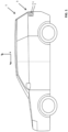
Figure 1 shows a side view of a vehicle comprising an optical assembly in accordance with an embodiment of the present invention incorporated into a vehicle lamp assembly; -
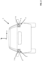
Figure 2 shows a rear view of the vehicle shown inFigure 1 ; -
Figure 3 shows a horizontal sectional view of the optical assembly shown inFigure 1 ; -
Figure 4 shows a vertical sectional view of the optical assembly shown inFigure 1 ; -
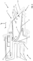
Figure 5 shows a rear elevation of the vehicle lamp assembly incorporating the optical assembly shown inFigure 1 . - An
optical assembly 1 for avehicle lamp assembly 3 in accordance with an embodiment of the present invention is described herein with reference to the accompanying Figures. - It will be understood that matching
vehicle lamp assemblies 3 are provided on the left and right sides of thevehicle 5. Theoptical assembly 1 has substantially the same configuration on each side of thevehicle 5. For the sake of brevity, a first one of theoptical assemblies 1 disposed in thevehicle lamp assembly 3 on the right-hand side of thevehicle 5 is described herein. - The
vehicle lamp assembly 3 is configured for installation in avehicle 5, such as an automobile, a sports utility vehicle or a utility vehicle. As shown inFigures 1 and2 , thevehicle lamp assembly 3 in the present embodiment is a rearvehicle lamp assembly 3 disposed at a rear of thevehicle 5. Thevehicle lamp assembly 3 may include one or more lamp unit 7-n. Thevehicle lamp assembly 3 may, for example, comprise one or more of the following lamp units 7-n: a tail lamp assembly (also known as a rear position lamp assembly); a stop lamp (brake light); a rear fog lamp; a reversing (backup) lamp; and a turn signal lamp. In a variant, thevehicle lamp assembly 3 may be a frontvehicle lamp assembly 3 disposed at a front of thevehicle 5. The frontvehicle lamp assembly 3 may comprise one or more of the following lamp unit 7-n: a head lamp; and a fog lamp. - As shown in
Figure 3 , thevehicle lamp assembly 3 comprises one or more light sources 9-n. The light sources 9-n each comprise at least one light emitting diode. Thevehicle lamp assembly 3 in the present embodiment comprises a plurality of the light sources 9-n. One or more of the light sources 9-n is associated with the or each lamp unit 7-n provided in thevehicle lamp assembly 3. The light sources 9-n are configured to emit light of a specific colour for the corresponding lamp unit 7-n. By way of example, the or each light source 9-n associated with a stop lamp 7-n is configured to emit red light; and the or each light source 9-n associated with a reversing lamp 7-n is configured to emit white light. - The
optical assembly 1 according to the present invention is configured to direct or guide the light emitted from the light sources 9-n. Theoptical assembly 1 will now be described with reference to a stop lamp unit 7-1 provided in thevehicle lamp assembly 3. It will be understood that the features of theoptical assembly 1 may be applied to other lamp units 7-1. The stop lamp unit 7-1 comprises a plurality of first light sources 9-1. The first light sources 9-1 are light emitting diodes which configured to emit red light when energized. As shown inFigure 2 , the stop lamp unit 7-1 forms avertical bar 11 when illuminated. It will be understood that the stop lamp unit 7-1 may be configured to form different shapes. - As shown in
Figure 3 , theoptical assembly 1 comprises atranslucent lens 11 for transmitting light emitted from the light sources 9-n. Thetranslucent lens 11 in the present embodiment has a low transmissivity. The transmissivity describes the proportion of electromagnetic radiation which is transmitted through thetranslucent lens 11, and has values between 0 and 1. The remaining portion of the electromagnetic radiation is either reflected or absorbed by thetranslucent lens 11. The electromagnetic radiation comprises or consists of visible electromagnetic radiation emitted from the light sources 9-n. Low transmissivity may be defined as a transmissivity of less than or equal to 0.5 (50%), 0.4 (40%), 0.3 (30%) or 0.2 (20%). The transmissivity of thetranslucent lens 11 in the present embodiment is approximately 0.2 (20%). Thetranslucent lens 11 in the present embodiment comprises atranslucent exterior lens 11 disposed on an outer surface of thevehicle 5. Thetranslucent exterior lens 11 is configured to transmit at least a portion of the light emitted by the light sources 9-n. Thetranslucent exterior lens 11 comprises a translucent lensouter surface 11A and a translucent lensinner surface 11B. The translucent lensouter surface 11A forms a portion of an outer A-surface of thevehicle 5. - The
optical assembly 1 comprises aninput optic 13 configured to direct light emitted by the light sources 9-n of thevehicle lamp assembly 3. Theinput optic 13 in the present embodiment comprises areflector 13. Thereflector 13 comprises alight input end 15 configured to receive light from the light sources 9-n; and alight output end 17 disposed proximal to thetranslucent exterior lens 11 and configured to output light received at thelight input end 15. Thereflector 13 has a concave profile and is configured to reflect light emitted by the light sources 9-n towards thelight output end 17. As shown inFigures 3 and4 , thereflector 13 is generally C-shaped in horizontal and vertical section. Thereflector 13 is moulded from a plastics material in the present embodiment and comprises a reflectiveinner surface 19. - As shown in
Figures 3 and5 , theoptical assembly 1 comprises adiffuser 21 to diffuse light emitted by the light sources 9-n. In use, thediffuser 21 scatters or diffuses the light. Thediffuser 21 in the present embodiment comprises a translucent material. Thediffuser 21 comprises a sheet member. Thediffuser 21 could have a rigid composition. In the present embodiment thediffuser 21 comprises a diffuser film. As shown inFigure 3 , thediffuser 21 is disposed between thelight output end 17 of thereflector 13 and thetranslucent exterior lens 11. Thediffuser 21 is disposed at thelight output end 17 of thereflector 13. Thediffuser 21 extends over thelight output end 17 of the reflector, as shown in Figure 13. Thediffuser 21 is fastened to thereflector 13. In particular, thediffuser 21 is fastened to thelight output end 17 of thereflector 13. Thediffuser 21 in the present embodiment is welded to thereflector 13. Thediffuser 21 is welded around a periphery of thelight output end 17 of thereflector 13. A weld line Ln formed around the periphery of thereflector 13 is represented inFigure 5 by a broken line. Other techniques may be used to fasten thediffuser 21 to thereflector 13. For example, thediffuser 21 may be bonded or clamped to thereflector 13. Thediffuser 21 has a planar composition to provide consistent diffusion. Thediffuser 21 may be secured under tension to thereflector 13. Thediffuser 21 comprises a diffuserouter surface 21A and a diffuserinner surface 21B. The diffuserouter surface 21A is oriented outwardly towards the translucent lensinner surface 11B. - The
diffuser 21 may be configured to provide substantially uniform optical diffusion over its surface. In the present embodiment, thediffuser 21 is configured to provide non-uniform optical diffusion over its surface. Thediffuser 21 comprises a patterned finish which varies optical diffusion over its surface. The pattern is formed by providing one or more opaque region on thediffuser 21. In the present embodiment, the one or more opaque region is formed by laser etching thediffuser 21. An enlarged view of a portion of thediffuser 21 is shown inFigure 5 illustrating an inclined slash pattern etched onto thediffuser 21. A plurality of the opaque regions may form a repeating pattern, such as a line pattern, a herring bone pattern, a stripe pattern, a wave pattern or a slash pattern. Each opaque region comprises a mark, such as a dot or a line, which is etched onto thediffuser 21. - The
optical assembly 1 comprises ahousing 25. The light sources 9-1, thetranslucent exterior lens 11 and thereflector 13 are mounted to thehousing 25. Thehousing 25 in the present embodiment is formed from metal and, in use, functions as a heat sink for dissipating heat generated by the at least one light source 9-1. Thehousing 25 comprises awall 27 and one ormore fins 29 to provide an increased surface area for heat dissipation. Thehousing 25 is mounted to a body 31 of thevehicle 5. The light sources 9-1 are mounted to thewall 27 of thehousing 25 to promote the dissipation of thermal energy. Acontrol unit 33 for thevehicle lamp assembly 3 may be provided in thehousing 25. - The
optical assembly 1 in accordance with the embodiment is configured to hide or obscure the features of thevehicle lamp assembly 3 until one or more of the lamp units 7-n is energised. This provides a hidden-till-lit arrangement for thevehicle lamp assembly 3. Thetranslucent lens 11 and/or thediffuser 21 are effective in hiding or obfuscating the interior of thevehicle lamp assembly 3. The individual lamp units 7-n contained within thevehicle lamp assembly 3 are not visible until the respective light sources 9-n are illuminated. - The
translucent lens 11 in the above embodiment has low transmissivity. Alternatively, or in addition, thetranslucent lens 11 may be configured to provide selective wavelength transmissivity. The selective wavelength transmissivity may facilitate transmission of electromagnetic radiation having a wavelength within a predefined range. Thetranslucent lens 11 may be configured to transmit electromagnetic radiation within the predefined range. Thetranslucent lens 11 may be configured selectively to transmit electromagnetic radiation emitted from the light sources 9-n while impeding or limiting transmission of electromagnetic radiation of other different frequencies. For example, thetranslucent lens 11 may selectively transmit electromagnetic radiation having a wavelength corresponding to a predominant wavelength of the electromagnetic radiation emitted from the associated light sources 9-n. In use, thetranslucent lens 11 may selectively permit transmission of electromagnetic radiation having a wavelength corresponding to a principal wavelength (or a principal wavelength range) of the electromagnetic radiation emitted by the light sources 9-n. Thetranslucent lens 11 may impede or limit transmission of electromagnetic radiation having a wavelength which is greater than or less than the principal wavelength (or a principal wavelength range) of the electromagnetic radiation emitted by the light sources 9-n. - As shown in
Figure 3 , thetranslucent lens 11 and thediffuser 21 are spaced apart from each other. A gap G is formed between thetranslucent lens 11 and thediffuser 21. In particular, the gap G is formed between the translucent lensinner surface 11B and the diffuserouter surface 21A. The gap G is at least substantially uniform over the entirety of thediffuser 21. By maintaining a substantially uniform gap G, the light emitted from theoptical assembly 1 may have improved uniformity. The gap G in the present embodiment is approximately 5mm (measured perpendicular to a surface of the diffuser). - The translucent lens
inner surface 11B has a first profile and the diffuserouter surface 21A has a second profile. The first and second profiles at least substantially match each other such that the gap G between thetranslucent lens 11 and thediffuser 21 is substantially uniform. The diffuserouter surface 21A may be curved in two dimensions or in three dimensions. In the present embodiment, the diffuserouter surface 21A is substantially planar in a horizontal XY plane (as shown inFigure 3 ); and is curved in a vertical YZ plane (as shown inFigure 4 ). It will be understood that thediffuser 21 may have other configurations. - The above embodiment relates to a
vehicle lamp assembly 3. Aspects of the present invention may be employed in a lighting unit used in other applications. For example, thetranslucent lens 11 and/or thediffuser 21 described herein may be used to hide or obfuscate the interior of the lighting unit. The lighting unit could be configured to provide a feature or detail on thevehicle 5 which is hidden from view when not illuminated. The lighting unit may be associated with a badge, a name or a logo provided on thevehicle 5. For example, the lighting unit may be configured selectively to display a manufacturer name on thevehicle 5. The lighting unit could be provided on a tailgate of the vehicle or in a light bar across the rear of the vehicle. It is envisaged that the space available to package the lighting unit may be less than for thevehicle lamp assembly 3 described herein. Thereflector 13 may be omitted or may be reduced in size to suit packaging requirements. - The
diffuser 21 in the embodiment described herein comprises a diffuser film. It will be understood that thediffuser 21 may be curved in two dimensions or in three dimensions. Thediffuser 21 may be self-supporting, for example having a rigid or resilient structure. Thediffuser 21 may be pre-formed. For example, thediffuser 21 could be moulded from a plastics material. - It will be appreciated that various changes and modifications can be made to the present invention without departing from the scope of the present application.
- The following aspects are also explicitly contemplated herein, as defined by the following Clauses:
-
Clause 1. An optical assembly for a vehicle lamp assembly, the optical assembly comprising:- a translucent lens;
- an input optic configured to direct light emitted by a light source of the vehicle lamp assembly, the input optic comprising:
- a light input end configured to receive light from the light source; and
- a light output end disposed proximal to the translucent lens and configured to output light received at the light input end, and
- a diffuser configured to diffuse light emitted by the light source, the diffuser being disposed between the light output end of the input optic and the translucent lens.
- Clause 2. An optical assembly as in
Clause 1 comprising a gap between the translucent lens and the diffuser; the gap being at least substantially uniform; optionally the gap is less than or equal to 5mm. -
Clause 3. An optical assembly as inClause 1 or Clause 2, wherein the translucent lens comprises a translucent lens inner surface and the diffuser comprises a diffuser outer surface; wherein the translucent lens inner surface and the diffuser outer surface have at least substantially matching profiles. - Clause 4. An optical assembly as in any one of the preceding Clauses, wherein the diffuser is disposed at the light output end of the input optic.
-
Clause 5. An optical assembly as in any one of the preceding Clauses, wherein the diffuser is fastened to the input optic; optionally the diffuser is welded to the light output end of the input optic; further optionally the diffuser is welded at least partially around a periphery of the light output end of the input optic. - Clause 6. An optical assembly as in any one of the preceding Clauses, wherein the diffuser comprises a diffuser film.
- Clause 7. An optical assembly as in any one of the preceding Clauses, wherein the diffuser comprises one or more opaque region; optionally the or each opaque region is laser etched in the diffuser.
- Clause 8. An optical assembly as in any one of the preceding Clauses comprising a metal housing for dissipating heat generated by the at least one light source.
- Clause 9. An optical assembly as in any one of the preceding Clauses, wherein the translucent lens has selective wavelength transmissivity.
- Clause 10. An optical assembly as in any one of the preceding Clauses, wherein the translucent lens has a low transmissivity.
-
Clause 11. An optical assembly for a vehicle lamp assembly, the optical assembly comprising:- a translucent lens; and
- an input optic for directing light emitted by an at least one light source, the input optic having a light output end disposed proximal to the translucent lens;
- wherein the translucent lens has a low transmissivity.
- Clause 12. An optical assembly as in Clause 10 or
Clause 11, wherein the low transmissivity of the translucent lens corresponds to a transmissivity of less than or equal to 40%. - Clause 12. A vehicle lamp assembly comprising an optical assembly as in any one of the preceding Clauses and at least one light source for emitting light.
-
Clause 13. A vehicle lamp assembly as inClause 19 comprising a plurality of the light sources, the light sources being configured to emit light of different colours. - Clause 14. A vehicle lamp assembly as in Clause 12 or
Clause 13 comprising a plurality of the input optics, the translucent lens being disposed in front of the plurality of input optics. -
Clause 15. A vehicle comprising one or more optical assembly as in any one ofClauses 1 to 11 and/or a vehicle lamp assembly according to any one of the Clauses 12 to 14.
Claims (15)
- An optical assembly (1) for a vehicle lamp assembly (3), the optical assembly (1) comprising:a translucent lens (11);an input optic (13) configured to direct light emitted by a light source (9-n) of the vehicle lamp assembly (3), the input optic (13) comprisinga light input end (15) configured to receive light from the light source (9-n), anda light output end (17) disposed proximal to the translucent lens (11) and configured to output light received at the light input end (15),a metal housing (25) comprising one or more fins (29) for dissipating heat generated by the light source (9-n); anda diffuser (21) fastened to the input optic (13) and configured to diffuse light emitted by the light source (9-n), the diffuser (21) being disposed between the light output end (17) of the input optic (13) and the translucent lens (11).
- An optical assembly (1) as claimed in claim 1 comprising a gap (G) between the translucent lens (11) and the diffuser (21); the gap (G) being at least substantially uniform; optionally the gap (G) is less than or equal to 5mm.
- An optical assembly (1) as claimed in claim 1 or 2, wherein the translucent lens (11) comprises a translucent lens inner surface (11B) and the diffuser (21) comprises a diffuser outer surface (21A); wherein the translucent lens inner surface (11B) and the diffuser outer surface (21A) have at least substantially matching profiles.
- An optical assembly (1) as claimed in any one of the preceding claims, wherein the diffuser (21) is disposed at the light output end (17) of the input optic (13).
- An optical assembly (1) as claimed in any one of the preceding claims, wherein the diffuser (21) is welded to the light output end (17) of the input optic (13).
- An optical assembly (1) as claimed in claim 5, wherein the diffuser (21) is welded at least partially around a periphery of the light output end (17) of the input optic (13).
- An optical assembly (1) as claimed in any one of the preceding claims, wherein the diffuser (21) comprises a diffuser film.
- An optical assembly (1) as claimed in any one of the preceding claims, wherein the diffuser (21) comprises one or more opaque region; optionally the or each opaque region is laser etched in the diffuser (21).
- An optical assembly (1) as claimed in any one of the preceding claims, wherein the translucent lens (11) has selective wavelength transmissivity.
- An optical assembly (1) as claimed in any one of the preceding claims, wherein a transmissivity of the translucent lens (11) corresponds to a transmissivity of less than or equal to 40%; less than or equal to 30%; or less than or equal to 20%.
- A vehicle lamp assembly (3) comprising an optical assembly (1) as claimed in any one of the preceding claims and at least one light source (9-n) for emitting light.
- A vehicle lamp assembly (3) as claimed in claim 11 comprising a plurality of the light sources (9-n), the light sources (9-n) being configured to emit light of different colours.
- A vehicle lamp assembly (3) as claimed in claim 11 or claim 12 comprising a plurality of the input optics (13), the translucent lens (11) being disposed in front of the plurality of input optics (13).
- A vehicle lamp assembly (3) as claimed in any one of claims 11 to 13, wherein the vehicle lamp assembly (3) comprises one or more of the following:a head lamp;a tail lamp;a side lamp;a fog lamp; anda daytime running lamp.
- A vehicle (5) comprising one or more optical assembly (1) as claimed in any one of claims 1 to 10 and/or a vehicle lamp assembly (3) according to any one of the claims 11 to 14.
Applications Claiming Priority (4)
| Application Number | Priority Date | Filing Date | Title |
|---|---|---|---|
| GB2115046.1A GB2612065B8 (en) | 2021-10-20 | 2021-10-20 | Optical assembly |
| GB2206480.2A GB2612155B (en) | 2021-10-20 | 2022-05-04 | Optical assembly |
| EP22808636.9A EP4419834B1 (en) | 2021-10-20 | 2022-10-18 | Optical assembly |
| PCT/EP2022/078916 WO2023066899A1 (en) | 2021-10-20 | 2022-10-18 | Optical assembly |
Related Parent Applications (2)
| Application Number | Title | Priority Date | Filing Date |
|---|---|---|---|
| EP22808636.9A Division EP4419834B1 (en) | 2021-10-20 | 2022-10-18 | Optical assembly |
| EP22808636.9A Division-Into EP4419834B1 (en) | 2021-10-20 | 2022-10-18 | Optical assembly |
Publications (1)
| Publication Number | Publication Date |
|---|---|
| EP4425043A1 true EP4425043A1 (en) | 2024-09-04 |
Family
ID=84360423
Family Applications (2)
| Application Number | Title | Priority Date | Filing Date |
|---|---|---|---|
| EP22808636.9A Active EP4419834B1 (en) | 2021-10-20 | 2022-10-18 | Optical assembly |
| EP24179091.4A Pending EP4425043A1 (en) | 2021-10-20 | 2022-10-18 | Optical assembly |
Family Applications Before (1)
| Application Number | Title | Priority Date | Filing Date |
|---|---|---|---|
| EP22808636.9A Active EP4419834B1 (en) | 2021-10-20 | 2022-10-18 | Optical assembly |
Country Status (2)
| Country | Link |
|---|---|
| EP (2) | EP4419834B1 (en) |
| WO (1) | WO2023066899A1 (en) |
Citations (13)
| Publication number | Priority date | Publication date | Assignee | Title |
|---|---|---|---|---|
| JPH09219105A (en) * | 1996-02-09 | 1997-08-19 | Koito Mfg Co Ltd | Light fixture |
| DE10101795A1 (en) * | 2001-01-17 | 2002-07-18 | Bosch Gmbh Robert | Flashing light, especially front flashing light, for motor vehicles has boundary light source in part of light conducting element in part of path of light from flashing light source |
| WO2012120441A1 (en) * | 2011-03-04 | 2012-09-13 | Automotive Lighting Italia S.P.A. | Automotive lighting unit |
| WO2013113728A1 (en) * | 2012-02-03 | 2013-08-08 | Automotive Lighting Rear Lamps France S.A.S. | Led lighting module for the rear lights of a motor vehicle |
| WO2014207414A2 (en) * | 2013-06-28 | 2014-12-31 | Automotive Lighting Rear Lamps France | Indirect lighting device for a motor vehicle tail light |
| DE102013110342A1 (en) * | 2013-09-19 | 2015-03-19 | Hella Kgaa Hueck & Co. | Lighting device for vehicles and light module |
| JP2017228490A (en) * | 2016-06-24 | 2017-12-28 | スタンレー電気株式会社 | Vehicle lighting |
| CN208011604U (en) * | 2017-12-25 | 2018-10-26 | 马瑞利汽车零部件(芜湖)有限公司 | A kind of car lamp device for realizing three-dimensional fish scale effect |
| US10371347B2 (en) * | 2016-11-30 | 2019-08-06 | Automotive Lighting Italia S.P.A. | Vehicle light comprising a portion of light emission with opalescent effect |
| EP3632749A1 (en) * | 2018-10-02 | 2020-04-08 | REHAU AG + Co | Translucent cladding section for a motor vehicle and method for producing a cladding section |
| US20200182428A1 (en) * | 2018-12-07 | 2020-06-11 | Marelli Automotive Lighting Italy S.p.A. | Vehicle Lighting and/or Signalling Device |
| US20210190285A1 (en) * | 2019-12-23 | 2021-06-24 | Flex-N-Gate France | Lighting device for vehicle |
| EP3848628A1 (en) * | 2020-01-09 | 2021-07-14 | Motherson Innovations Company Limited | A light emitting system, a design element, a rear view device, a covering device, and a body component of a vehicle |
Family Cites Families (2)
| Publication number | Priority date | Publication date | Assignee | Title |
|---|---|---|---|---|
| EP3476658B1 (en) * | 2017-10-26 | 2020-05-13 | International Automotive Components Group GmbH | Trim part |
| EP3882085B1 (en) * | 2018-11-14 | 2026-01-28 | Shanghai Yanfeng Jinqiao Automotive Trim Systems Co., Ltd. | Vehicle interior trim piece |
-
2022
- 2022-10-18 EP EP22808636.9A patent/EP4419834B1/en active Active
- 2022-10-18 WO PCT/EP2022/078916 patent/WO2023066899A1/en not_active Ceased
- 2022-10-18 EP EP24179091.4A patent/EP4425043A1/en active Pending
Patent Citations (13)
| Publication number | Priority date | Publication date | Assignee | Title |
|---|---|---|---|---|
| JPH09219105A (en) * | 1996-02-09 | 1997-08-19 | Koito Mfg Co Ltd | Light fixture |
| DE10101795A1 (en) * | 2001-01-17 | 2002-07-18 | Bosch Gmbh Robert | Flashing light, especially front flashing light, for motor vehicles has boundary light source in part of light conducting element in part of path of light from flashing light source |
| WO2012120441A1 (en) * | 2011-03-04 | 2012-09-13 | Automotive Lighting Italia S.P.A. | Automotive lighting unit |
| WO2013113728A1 (en) * | 2012-02-03 | 2013-08-08 | Automotive Lighting Rear Lamps France S.A.S. | Led lighting module for the rear lights of a motor vehicle |
| WO2014207414A2 (en) * | 2013-06-28 | 2014-12-31 | Automotive Lighting Rear Lamps France | Indirect lighting device for a motor vehicle tail light |
| DE102013110342A1 (en) * | 2013-09-19 | 2015-03-19 | Hella Kgaa Hueck & Co. | Lighting device for vehicles and light module |
| JP2017228490A (en) * | 2016-06-24 | 2017-12-28 | スタンレー電気株式会社 | Vehicle lighting |
| US10371347B2 (en) * | 2016-11-30 | 2019-08-06 | Automotive Lighting Italia S.P.A. | Vehicle light comprising a portion of light emission with opalescent effect |
| CN208011604U (en) * | 2017-12-25 | 2018-10-26 | 马瑞利汽车零部件(芜湖)有限公司 | A kind of car lamp device for realizing three-dimensional fish scale effect |
| EP3632749A1 (en) * | 2018-10-02 | 2020-04-08 | REHAU AG + Co | Translucent cladding section for a motor vehicle and method for producing a cladding section |
| US20200182428A1 (en) * | 2018-12-07 | 2020-06-11 | Marelli Automotive Lighting Italy S.p.A. | Vehicle Lighting and/or Signalling Device |
| US20210190285A1 (en) * | 2019-12-23 | 2021-06-24 | Flex-N-Gate France | Lighting device for vehicle |
| EP3848628A1 (en) * | 2020-01-09 | 2021-07-14 | Motherson Innovations Company Limited | A light emitting system, a design element, a rear view device, a covering device, and a body component of a vehicle |
Also Published As
| Publication number | Publication date |
|---|---|
| WO2023066899A1 (en) | 2023-04-27 |
| EP4419834C0 (en) | 2025-09-17 |
| EP4419834B1 (en) | 2025-09-17 |
| EP4419834A1 (en) | 2024-08-28 |
Similar Documents
| Publication | Publication Date | Title |
|---|---|---|
| EP2157363B1 (en) | Optical element for vehicle lamp | |
| US6315437B1 (en) | Outside rear view mirror | |
| JP6868974B2 (en) | Light fixtures for vehicles | |
| JP2010040322A (en) | Lighting fixture for vehicle | |
| JP6655347B2 (en) | Lighting holding structure for vehicles | |
| JP6609135B2 (en) | Rear combination lamp for vehicles | |
| JP2013232405A (en) | Lighting device, vehicle lamp, vehicle brake lamp, vehicle turn indicator lamp, vehicle auxiliary lamp, and vehicle headlamp | |
| KR101804311B1 (en) | Back light unit | |
| JP2013222540A (en) | Lamp fitting for vehicle | |
| JP2019050131A (en) | Vehicle lamp | |
| JP2019023965A (en) | Vehicle lighting | |
| JP6975587B2 (en) | Vehicle lighting | |
| JP7307538B2 (en) | vehicle lamp | |
| JP2015185524A (en) | Lighting tool for vehicle | |
| JP7145644B2 (en) | vehicle lamp | |
| WO2023066899A1 (en) | Optical assembly | |
| KR20230095228A (en) | Lamp for vehicle | |
| GB2612155A (en) | Optical assembly | |
| US20190032883A1 (en) | Pattern styling for reducing glare in vehicle lighting assemblies | |
| JP7022224B2 (en) | Vehicle lighting | |
| JP2014067515A (en) | Lighting fixture for vehicle | |
| JP4398452B2 (en) | Interior materials with indirect lighting equipment for automobiles | |
| JP7193276B2 (en) | vehicle lamp | |
| JP2010170983A (en) | Lighting fixture for vehicle | |
| EP3561374B1 (en) | Vehicular lamp |
Legal Events
| Date | Code | Title | Description |
|---|---|---|---|
| PUAI | Public reference made under article 153(3) epc to a published international application that has entered the european phase |
Free format text: ORIGINAL CODE: 0009012 |
|
| STAA | Information on the status of an ep patent application or granted ep patent |
Free format text: STATUS: THE APPLICATION HAS BEEN PUBLISHED |
|
| AC | Divisional application: reference to earlier application |
Ref document number: 4419834 Country of ref document: EP Kind code of ref document: P |
|
| AK | Designated contracting states |
Kind code of ref document: A1 Designated state(s): AL AT BE BG CH CY CZ DE DK EE ES FI FR GB GR HR HU IE IS IT LI LT LU LV MC ME MK MT NL NO PL PT RO RS SE SI SK SM TR |
|
| P01 | Opt-out of the competence of the unified patent court (upc) registered |
Free format text: CASE NUMBER: APP_67803/2024 Effective date: 20241223 |
|
| STAA | Information on the status of an ep patent application or granted ep patent |
Free format text: STATUS: REQUEST FOR EXAMINATION WAS MADE |
|
| 17P | Request for examination filed |
Effective date: 20250304 |
|
| STAA | Information on the status of an ep patent application or granted ep patent |
Free format text: STATUS: EXAMINATION IS IN PROGRESS |
|
| 17Q | First examination report despatched |
Effective date: 20250424 |