EP4425006A1 - Rolling bearing - Google Patents
Rolling bearing Download PDFInfo
- Publication number
- EP4425006A1 EP4425006A1 EP22886693.5A EP22886693A EP4425006A1 EP 4425006 A1 EP4425006 A1 EP 4425006A1 EP 22886693 A EP22886693 A EP 22886693A EP 4425006 A1 EP4425006 A1 EP 4425006A1
- Authority
- EP
- European Patent Office
- Prior art keywords
- rolling bearing
- ring
- housing
- axial direction
- peripheral groove
- Prior art date
- Legal status (The legal status is an assumption and is not a legal conclusion. Google has not performed a legal analysis and makes no representation as to the accuracy of the status listed.)
- Pending
Links
Images



Classifications
-
- F—MECHANICAL ENGINEERING; LIGHTING; HEATING; WEAPONS; BLASTING
- F16—ENGINEERING ELEMENTS AND UNITS; GENERAL MEASURES FOR PRODUCING AND MAINTAINING EFFECTIVE FUNCTIONING OF MACHINES OR INSTALLATIONS; THERMAL INSULATION IN GENERAL
- F16C—SHAFTS; FLEXIBLE SHAFTS; ELEMENTS OR CRANKSHAFT MECHANISMS; ROTARY BODIES OTHER THAN GEARING ELEMENTS; BEARINGS
- F16C19/00—Bearings with rolling contact, for exclusively rotary movement
- F16C19/02—Bearings with rolling contact, for exclusively rotary movement with bearing balls essentially of the same size in one or more circular rows
- F16C19/04—Bearings with rolling contact, for exclusively rotary movement with bearing balls essentially of the same size in one or more circular rows for radial load mainly
- F16C19/06—Bearings with rolling contact, for exclusively rotary movement with bearing balls essentially of the same size in one or more circular rows for radial load mainly with a single row or balls
-
- F—MECHANICAL ENGINEERING; LIGHTING; HEATING; WEAPONS; BLASTING
- F16—ENGINEERING ELEMENTS AND UNITS; GENERAL MEASURES FOR PRODUCING AND MAINTAINING EFFECTIVE FUNCTIONING OF MACHINES OR INSTALLATIONS; THERMAL INSULATION IN GENERAL
- F16C—SHAFTS; FLEXIBLE SHAFTS; ELEMENTS OR CRANKSHAFT MECHANISMS; ROTARY BODIES OTHER THAN GEARING ELEMENTS; BEARINGS
- F16C33/00—Parts of bearings; Special methods for making bearings or parts thereof
- F16C33/30—Parts of ball or roller bearings
- F16C33/58—Raceways; Race rings
- F16C33/583—Details of specific parts of races
- F16C33/586—Details of specific parts of races outside the space between the races, e.g. end faces or bore of inner ring
-
- F—MECHANICAL ENGINEERING; LIGHTING; HEATING; WEAPONS; BLASTING
- F16—ENGINEERING ELEMENTS AND UNITS; GENERAL MEASURES FOR PRODUCING AND MAINTAINING EFFECTIVE FUNCTIONING OF MACHINES OR INSTALLATIONS; THERMAL INSULATION IN GENERAL
- F16C—SHAFTS; FLEXIBLE SHAFTS; ELEMENTS OR CRANKSHAFT MECHANISMS; ROTARY BODIES OTHER THAN GEARING ELEMENTS; BEARINGS
- F16C35/00—Rigid support of bearing units; Housings, e.g. caps, covers
- F16C35/04—Rigid support of bearing units; Housings, e.g. caps, covers in the case of ball or roller bearings
- F16C35/06—Mounting or dismounting of ball or roller bearings; Fixing them onto shaft or in housing
- F16C35/067—Fixing them in a housing
-
- F—MECHANICAL ENGINEERING; LIGHTING; HEATING; WEAPONS; BLASTING
- F16—ENGINEERING ELEMENTS AND UNITS; GENERAL MEASURES FOR PRODUCING AND MAINTAINING EFFECTIVE FUNCTIONING OF MACHINES OR INSTALLATIONS; THERMAL INSULATION IN GENERAL
- F16J—PISTONS; CYLINDERS; SEALINGS
- F16J15/00—Sealings
- F16J15/02—Sealings between relatively-stationary surfaces
- F16J15/06—Sealings between relatively-stationary surfaces with solid packing compressed between sealing surfaces
- F16J15/062—Sealings between relatively-stationary surfaces with solid packing compressed between sealing surfaces characterised by the geometry of the seat
-
- F—MECHANICAL ENGINEERING; LIGHTING; HEATING; WEAPONS; BLASTING
- F16—ENGINEERING ELEMENTS AND UNITS; GENERAL MEASURES FOR PRODUCING AND MAINTAINING EFFECTIVE FUNCTIONING OF MACHINES OR INSTALLATIONS; THERMAL INSULATION IN GENERAL
- F16C—SHAFTS; FLEXIBLE SHAFTS; ELEMENTS OR CRANKSHAFT MECHANISMS; ROTARY BODIES OTHER THAN GEARING ELEMENTS; BEARINGS
- F16C2240/00—Specified values or numerical ranges of parameters; Relations between them
- F16C2240/40—Linear dimensions, e.g. length, radius, thickness, gap
- F16C2240/42—Groove sizes
-
- F—MECHANICAL ENGINEERING; LIGHTING; HEATING; WEAPONS; BLASTING
- F16—ENGINEERING ELEMENTS AND UNITS; GENERAL MEASURES FOR PRODUCING AND MAINTAINING EFFECTIVE FUNCTIONING OF MACHINES OR INSTALLATIONS; THERMAL INSULATION IN GENERAL
- F16C—SHAFTS; FLEXIBLE SHAFTS; ELEMENTS OR CRANKSHAFT MECHANISMS; ROTARY BODIES OTHER THAN GEARING ELEMENTS; BEARINGS
- F16C27/00—Elastic or yielding bearings or bearing supports, for exclusively rotary movement
- F16C27/06—Elastic or yielding bearings or bearing supports, for exclusively rotary movement by means of parts of rubber or like materials
- F16C27/066—Ball or roller bearings
-
- F—MECHANICAL ENGINEERING; LIGHTING; HEATING; WEAPONS; BLASTING
- F16—ENGINEERING ELEMENTS AND UNITS; GENERAL MEASURES FOR PRODUCING AND MAINTAINING EFFECTIVE FUNCTIONING OF MACHINES OR INSTALLATIONS; THERMAL INSULATION IN GENERAL
- F16C—SHAFTS; FLEXIBLE SHAFTS; ELEMENTS OR CRANKSHAFT MECHANISMS; ROTARY BODIES OTHER THAN GEARING ELEMENTS; BEARINGS
- F16C35/00—Rigid support of bearing units; Housings, e.g. caps, covers
- F16C35/04—Rigid support of bearing units; Housings, e.g. caps, covers in the case of ball or roller bearings
- F16C35/06—Mounting or dismounting of ball or roller bearings; Fixing them onto shaft or in housing
- F16C35/07—Fixing them on the shaft or housing with interposition of an element
- F16C35/077—Fixing them on the shaft or housing with interposition of an element between housing and outer race ring
Definitions
- the present invention relates to a rolling bearing.
- a repulsive force of the O-ring against the housing be high for improvement of hermeticity and vibration absorbing property using the O-ring.
- the O-ring is likely to be broken or ruptured in an attachment process of mounting the rolling bearing at the housing.
- an object is to provide a rolling bearing capable of suppressing breakage of an O-ring.
- a rolling bearing in one mode, includes an outer ring, an inner ring, a rolling element disposed in a rollable manner between the outer ring and the inner ring, and an O-ring made of an elastic body and fitted to a peripheral groove provided at an outer peripheral surface of the outer ring.
- a first bottom surface is provided at a center of the peripheral groove in an axial direction
- a second bottom surface is provided at an end part of the first bottom surface in the axial direction.
- the second bottom surface extends in a circumferential direction and has a smaller diameter than the first bottom surface.
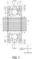
- FIG. 1 is a side cross-sectional view illustrating an example of the rolling bearing according to the embodiment.
- FIG. 1 illustrates a cross section of the annular rolling bearing 20 taken along the diameter of the rolling bearing 20. That is, a configuration illustrated at an upper part of FIG. 1 and a configuration illustrated at a lower part of FIG. 1 indicate an upper part and a lower part of an annular member with some exceptions.
- the rolling bearing 20 includes an outer ring 30, an inner ring 40 disposed at an inner peripheral side of the outer ring 30, a plurality of spherical rolling elements 23, a retainer 24, and a seal member 25.
- the inside sealed by the seal member 25 is filled with grease G.
- the seal member 25 and the retainer 24 are not essential.
- a full ball bearing not including the retainer 24 is also included in the technical scope of the present invention.
- the plurality of rolling elements 23 are, for example, metal spheres and are provided in a rollable manner between a raceway groove 32 of the outer ring 30 and a raceway groove 42 of the inner ring 40.
- the plurality of rolling elements 23 are disposed at equal intervals in the circumferential direction. In FIG. 1 , only some of the rolling elements 23a and 23n are illustrated among the plurality of rolling elements 23.
- the retainer 24 includes pockets rotatably retaining the rolling elements 23.
- the grease G is disposed in a bearing space surrounded by the outer ring 30 and the inner ring 40.
- the grease G is sealed at the inner peripheral surface side of the outer ring 30 at both of one side in the axial direction and another side in the axial direction across the plurality of rolling elements 23 in the bearing space.
- the volume of the sealed grease G is, for example, 3 to 60% of the volume of the bearing space.
- the rolling bearing 20 rotatably supports the shaft 80. Moreover, the rolling bearing 20 is mounted such that the rolling bearing 20 is inserted into a housing 70 of a fan motor, a pump, a valve opening/closing mechanism, a transmission, or the like. At this time, an O-ring 60 made of an elastic body such as rubber is disposed between the rolling bearing 20 and the housing 70 in the radial direction to, for example, achieve hermeticity and absorb vibrations. In the embodiment, the O-ring 60 is disposed such that the O-ring 60 is fitted to a peripheral groove 50 formed at an outer peripheral surface 31 of the outer ring 30 of the rolling bearing 20.
- the peripheral groove 50 is formed in the circumferential direction along the outer peripheral surface 31 of the outer ring 30 of the rolling bearing 20.
- a plurality of the peripheral grooves 50 are arranged at equal intervals in the axial direction.
- the O-ring 60 may be fitted to only one of the plurality of formed peripheral grooves 50 or may be fitted to both of the peripheral grooves 50.
- only one peripheral groove 50 may be provided at the outer peripheral surface 31.
- the rolling bearing 20 according to the embodiment includes two peripheral grooves 50a and 50b formed to be spaced apart in the axial direction. Note that, in the following, the peripheral grooves 50a and 50b, when expressed without distinction, may be simply expressed as peripheral grooves 50.
- the elastic body forming the O-ring 60 for example, a known rubber such as NBR, hydrogenated NBR, EPDM, acrylic rubber, or fluorine rubber is used. Note that the elastic body forming the O-ring 60 desirably has heat resistance, oil resistance, cold resistance, and chemical resistance in accordance with usage of the O-ring 60.
- the O-ring 60 is disposed at each of the peripheral grooves 50a and 50b. That is, in the embodiment, two O-rings 60a and 60b are disposed at the rolling bearing 20. Note that, in the following, the O-rings 60a and 60b, when expressed without distinction, may be simply expressed as O-rings 60.
- FIG. 2 is an enlarged cross-sectional view illustrating an example of the peripheral groove of the rolling bearing according to the embodiment.
- FIG. 2 is an enlarged view of a part illustrated in a frame F1 of FIG. 1 .
- the peripheral groove 50 include a first bottom surface 51, two second bottom surfaces 52a and 52b, and two sidewalls 55a and 55b.
- the second bottom surfaces 52a and 52b when expressed without distinction, may be simply expressed as second bottom surfaces 52
- the sidewalls 55a and 55b when expressed without distinction, may be simply expressed as sidewalls 55.
- the sidewalls 55 are formed substantially parallel to the radial direction. That is, in the embodiment, neither a part protruding nor a part notched in the axial direction is formed at the peripheral groove 50.
- the first bottom surface 51 of the peripheral groove 50 extends in the circumferential direction of the rolling bearing 20.
- the first bottom surface 51 is formed such that the distance to the housing 70 and the distance to the shaft 80 are substantially constant in the radial direction.
- the cross section of the first bottom surface 51 in the axial direction has a linear shape substantially parallel to the axial direction.
- the second bottom surfaces 52a and 52b extend in the circumferential direction in a manner similar to the first bottom surface 51 and are formed adjacent to the first bottom surface 51 in the axial direction. That is, the first bottom surface 51 is provided at the center of the peripheral groove 50 in the axial direction, and the pair of second bottom surfaces 52a and 52b are provided at both ends of the first bottom surface 51 in the axial direction.
- the second bottom surface 52a is in contact with the first bottom surface 51 at a contact point 59 illustrated in FIG. 2 .
- the second bottom surfaces 52 are formed radially inward of the first bottom surface 51 by a size D1. That is, the sizes of the second bottom surfaces 52 in the radial direction are smaller than the size of the first bottom surface 51 in the radial direction.
- outer end parts of the second bottom surfaces 52 in the axial direction are located inward of the sidewalls 55 in the axial direction.
- a left end part of the second bottom surface 52a in the drawing is located at the right side of the sidewall 55a in the drawing
- a right end part of the second bottom surface 52b in the drawing is located at the left side of the sidewall 55b in the drawing.
- the second bottom surfaces 52 may be formed such that the distances to the housing 70 and the distances to the shaft 80 in the radial direction change.
- outer parts of the second bottom surfaces 52 that is, parts in contact with the sidewalls 55 and parts in contact with the first bottom surface 51 have larger sizes in the radial direction than central parts of the second bottom surfaces 52.
- the sizes of the second bottom surfaces 52 in the radial direction continuously change in the axial direction. That is, the cross sections of the second bottom surfaces 52 in the axial direction have arc shapes as illustrated in FIG. 2 .
- the first bottom surface 51 and the second bottom surfaces 52 are not continuous. For example, as illustrated in FIG. 2 , parts substantially parallel to the axial direction are not formed at parts of the second bottom surfaces 52 in contact with the first bottom surface 51.
- the first bottom surface 51 is formed to occupy a certain part of the peripheral groove 50 in the axial direction.
- the peripheral groove 50 according to the embodiment is formed such that, for example, a length L1 of the first bottom surface 51 in the axial direction is 40% or more of a length L0 of the peripheral groove 50 in the axial direction, that is, the distance between the sidewalls 55a and 55b.
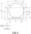
- FIG. 3 is an enlarged cross-sectional view illustrating an example of the peripheral groove.
- the O-ring according to the embodiment is disposed.
- a distance H1 from the first bottom surface 51 of the peripheral groove 50 to the outer peripheral surface 31 of the outer ring 30 of the rolling bearing 20 is smaller than a diameter R1 of the O-ring 60.
- the length L0 of the peripheral groove 50 in the axial direction is larger than the diameter R1 of the O-ring 60.
- the O-ring 60 disposed at the peripheral groove 50 protrudes radially outward relative to the peripheral groove 50 but is not in contact with at least one of the sidewalls 55a and 55b.
- FIGS. 4A and 4B are enlarged cross-sectional views illustrating examples of a process of attaching the rolling bearing according to the embodiment to the housing.
- FIG. 5 is an enlarged perspective view illustrating an example of the rolling bearing attached to the housing according to the embodiment.
- the depth of color of the pressed and deformed O-ring 60 indicates the strength of a stress applied to the O-ring 60.
- the housing 70 moves relative to the rolling bearing 20 in a direction indicated by an arrow in FIG. 4A from the right direction to the left direction in the drawing, that is, from a direction of the positions of the sidewall 55b and the second bottom surface 52b to a direction of the positions of the sidewall 55a and the second bottom surface 52a.
- a part 61 (first part 61) of the O-ring 60 protruding radially outward from the peripheral groove 50 in FIG. 3 is pressed by the housing 70 leftward in the drawing and deformed.
- the O-ring 60 in contact with the sidewall 55b moves toward the sidewall 55a, and a stress is applied to the deformed O-ring 60 with the first part 61 as the center as illustrated in FIG. 4A .
- the housing 70 further moves relative to the rolling bearing 20, and thus another part 62 (second part 62) of the pressed and deformed O-ring 60 moves to a position close to the one second bottom surface 52a of the peripheral groove 50 (the second bottom surface located at a position approached by the housing 70 later). Further, still another part 63 (third part 63) of the O-ring 60 moves to a position close to the other second bottom surface 52b of the peripheral groove 50 (the second bottom surface in position to approach the housing 70 first).
- the O-ring 60 is accommodated in the peripheral groove 50 without substantially protruding radially outward relative to the outer peripheral surface 31 of the outer ring 30 of the rolling bearing 20.
- the second part 62 is larger than the third part 63.
- a large stress is applied to the first part 61 when the outer ring 30 is fitted to the housing 70 with the O-ring 60 disposed at the outer ring 30.
- a stress applied to the O-ring 60 is not concentrated only on the first part 61, but is dispersed to the other parts.
- a stress applied to the first part 61 is smaller than a stress applied to a part 69 (fourth part 69) close to the first bottom surface 51 of the peripheral groove 50. In this case, rupture of the O-ring 60 in the attachment process is suppressed.
- the O-ring 60 is pressed and deformed, and as a result, the second part 62 is in contact with the one second bottom surface 52a in the radial direction and the third part 63 is in contact with the other second bottom surface 52b in the radial direction. Further, the fourth part 69 of the O-ring 60 is in contact with the first bottom surface 51 of the peripheral groove 50 in the radial direction.
- the parts of the O-ring 60 protrude radially inward relative to the first bottom surface 51 at both sides of the first bottom surface 51 in the axial direction, so that the O-ring 60 has a substantially C shape as illustrated in FIG. 5 .
- the second part 62 and the third part 63 are not necessarily in contact with the second bottom surface 52a and the second bottom surface 52b, respectively.
- the fourth part 69 of the O-ring 60 is preferably in contact with the first bottom surface 51 of the peripheral groove 50 over the entirety of the first bottom surface 51 in the axial direction.
- the deformed O-ring 60 is preferably in contact not only with the contact point 59 between the first bottom surface 51 and the second bottom surface 52a but also with a contact point between the first bottom surface 51 and the second bottom surface 52b.
- a larger stress is applied from the first bottom surface 51 to the fourth part 69 in contact with the first bottom surface 51.
- a corner part abuts against the O-ring 60, thereby further increasing a stress.
- the deformed O-ring 60 having a substantially C-shaped cross section attempts to return to have an O-shaped cross section, and thus the stress acts as a repulsive force against the housing 70.
- the O-ring 60 can exert a sufficient repulsive force against the housing 70.
- the rolling bearing 20 includes the outer ring 30, the inner ring 40, the rolling elements 23 disposed in a rollable manner between the outer ring 30 and the inner ring 40, and the O-ring 60 made of an elastic body and fitted to the peripheral groove 50 provided at the outer peripheral surface 31 of the outer ring 30.
- the first bottom surface 51 is provided at the center of the peripheral groove 50 in the axial direction, and the second bottom surfaces 52a and 52b extending in the circumferential direction and having smaller diameters than the first bottom surface are provided at the end parts of the first bottom surface 51 in the axial direction. According to such a configuration, rupture of the O-ring 60 is suppressed, and the repulsive force of the O-ring 60 against the housing 70 can be obtained.
- the length L1 of the first bottom surface 51 in the axial direction is 40% or more of the length L0 of the entire peripheral groove 50 in the axial direction.
- the first bottom surface 51 is formed such that the distance between the first bottom surface 51 and the housing 70 in the radial direction is substantially constant. According to such a configuration, a sufficient contact area is obtained between the first bottom surface 51 and the O-ring 60 in the radial direction, and thus a stress applied to the O-ring 60 in the radial direction is increased.
- the fourth part 69 of the O-ring 60 is preferably in contact with the first bottom surface 51 of the peripheral groove 50 over the entirety of the first bottom surface 51 in the axial direction.
- first bottom surface 51 and the second bottom surfaces 52a and 52b are not formed so as to be continuous in the axial direction. Such a configuration suppresses the stress applied to the O-ring 60 being escaped in the axial direction, and thus the repulsive force against the housing 70 is obtained.
- the second bottom surfaces 52a and 52b are formed so as to be symmetrical, for example, in the axial direction, but no such limitation is intended in the embodiment.
- the two second bottom surfaces 52a and 52b may be asymmetric in the axial direction, or only one second bottom surface may be formed.
- the peripheral groove 50 may be configured so as not to include the second bottom surface 52b.
Landscapes
- Engineering & Computer Science (AREA)
- General Engineering & Computer Science (AREA)
- Mechanical Engineering (AREA)
- Physics & Mathematics (AREA)
- Geometry (AREA)
- Rolling Contact Bearings (AREA)
- Support Of The Bearing (AREA)
- Mounting Of Bearings Or Others (AREA)
Abstract
Description
- The present invention relates to a rolling bearing.
- There has been known a technique for mounting an O-ring made of an elastic body at an outer peripheral surface of a bearing ring of a rolling bearing to achieve hermeticity and absorb vibration of a device mounted with the rolling bearing at a housing.
-
- Patent Document 1:
JP 5505549 B - Patent Document 2:
JP 2015-72034 A - It is desirable that a repulsive force of the O-ring against the housing be high for improvement of hermeticity and vibration absorbing property using the O-ring. However, in this case, the O-ring is likely to be broken or ruptured in an attachment process of mounting the rolling bearing at the housing.
- In one aspect, an object is to provide a rolling bearing capable of suppressing breakage of an O-ring.
- In one mode, a rolling bearing includes an outer ring, an inner ring, a rolling element disposed in a rollable manner between the outer ring and the inner ring, and an O-ring made of an elastic body and fitted to a peripheral groove provided at an outer peripheral surface of the outer ring. A first bottom surface is provided at a center of the peripheral groove in an axial direction, and
a second bottom surface is provided at an end part of the first bottom surface in the axial direction. The second bottom surface extends in a circumferential direction and has a smaller diameter than the first bottom surface. - According to the one mode, it is possible to suppress breakage of the O-ring.
-
-
FIG. 1 is a side cross-sectional view illustrating an example of a rolling bearing according to an embodiment. -
FIG. 2 is an enlarged cross-sectional view illustrating an example of a peripheral groove of a rolling bearing according to an embodiment. -
FIG. 3 is an enlarged cross-sectional view illustrating an example of a peripheral groove. At the peripheral groove, an O-ring according to an embodiment is disposed. -
FIG. 4A is an enlarged cross-sectional view illustrating an example of a process of attaching a rolling bearing according to an embodiment to a housing. -
FIG. 4B is an enlarged cross-sectional view illustrating an example of a process of attaching a rolling bearing according to an embodiment to the housing. -
FIG. 5 is an enlarged perspective view illustrating an example of a rolling bearing attached to a housing according to an embodiment. - An embodiment of a rolling bearing disclosed in the present application will be described below in detail with reference to the drawings. Note that dimensional relationships between elements and scales of elements in the drawings may differ from actual configurations. The drawings may include parts having mutually different dimensional relationships and scales. For the sake of clarity of description, a coordinate system with an extension direction of a below-described
shaft 80 defined as an axial direction may be illustrated in the drawings. In addition, a circumferential direction and a radial direction in the following description indicate a circumferential direction and a radial direction of a rollingbearing 20 described below. - First, a rolling bearing according to the embodiment will be described.
FIG. 1 is a side cross-sectional view illustrating an example of the rolling bearing according to the embodiment.FIG. 1 illustrates a cross section of the annular rollingbearing 20 taken along the diameter of the rolling bearing 20. That is, a configuration illustrated at an upper part ofFIG. 1 and a configuration illustrated at a lower part ofFIG. 1 indicate an upper part and a lower part of an annular member with some exceptions. - As illustrated in
FIG. 1 , therolling bearing 20 according to the embodiment includes anouter ring 30, aninner ring 40 disposed at an inner peripheral side of theouter ring 30, a plurality of sphericalrolling elements 23, a retainer 24, and aseal member 25. The inside sealed by theseal member 25 is filled with grease G. Note that theseal member 25 and the retainer 24 are not essential. A full ball bearing not including the retainer 24 is also included in the technical scope of the present invention. - The plurality of
rolling elements 23 are, for example, metal spheres and are provided in a rollable manner between araceway groove 32 of theouter ring 30 and araceway groove 42 of theinner ring 40. For example, the plurality ofrolling elements 23 are disposed at equal intervals in the circumferential direction. InFIG. 1 , only some of therolling elements rolling elements 23. - The retainer 24 includes pockets rotatably retaining the
rolling elements 23. The grease G is disposed in a bearing space surrounded by theouter ring 30 and theinner ring 40. In addition, the grease G is sealed at the inner peripheral surface side of theouter ring 30 at both of one side in the axial direction and another side in the axial direction across the plurality ofrolling elements 23 in the bearing space. The volume of the sealed grease G is, for example, 3 to 60% of the volume of the bearing space. - The rolling bearing 20 according to the embodiment rotatably supports the
shaft 80. Moreover, the rollingbearing 20 is mounted such that the rollingbearing 20 is inserted into ahousing 70 of a fan motor, a pump, a valve opening/closing mechanism, a transmission, or the like. At this time, an O-ring 60 made of an elastic body such as rubber is disposed between the rolling bearing 20 and thehousing 70 in the radial direction to, for example, achieve hermeticity and absorb vibrations. In the embodiment, the O-ring 60 is disposed such that the O-ring 60 is fitted to aperipheral groove 50 formed at an outerperipheral surface 31 of theouter ring 30 of the rollingbearing 20. - The
peripheral groove 50 is formed in the circumferential direction along the outerperipheral surface 31 of theouter ring 30 of the rollingbearing 20. For example, a plurality of theperipheral grooves 50 are arranged at equal intervals in the axial direction. In this case, the O-ring 60 may be fitted to only one of the plurality of formedperipheral grooves 50 or may be fitted to both of theperipheral grooves 50. Further, only oneperipheral groove 50 may be provided at the outerperipheral surface 31. As illustrated inFIG. 1 , the rolling bearing 20 according to the embodiment includes twoperipheral grooves peripheral grooves peripheral grooves 50. - As the elastic body forming the O-
ring 60, for example, a known rubber such as NBR, hydrogenated NBR, EPDM, acrylic rubber, or fluorine rubber is used. Note that the elastic body forming the O-ring 60 desirably has heat resistance, oil resistance, cold resistance, and chemical resistance in accordance with usage of the O-ring 60. - In the embodiment, the O-
ring 60 is disposed at each of theperipheral grooves rings bearing 20. Note that, in the following, the O-rings rings 60. - As illustrated in
FIGS. 1 and2 , a plurality of bottom surfaces having different depths in the radial direction are formed at theperipheral grooves 50.FIG. 2 is an enlarged cross-sectional view illustrating an example of the peripheral groove of the rolling bearing according to the embodiment.FIG. 2 is an enlarged view of a part illustrated in a frame F1 ofFIG. 1 . - As illustrated in
FIG. 2 , theperipheral groove 50 include afirst bottom surface 51, two second bottom surfaces 52a and 52b, and twosidewalls sidewalls - The sidewalls 55 are formed substantially parallel to the radial direction. That is, in the embodiment, neither a part protruding nor a part notched in the axial direction is formed at the
peripheral groove 50. - The
first bottom surface 51 of theperipheral groove 50 extends in the circumferential direction of the rollingbearing 20. In the embodiment, thefirst bottom surface 51 is formed such that the distance to thehousing 70 and the distance to theshaft 80 are substantially constant in the radial direction. In this case, as illustrated inFIG. 2 , the cross section of thefirst bottom surface 51 in the axial direction has a linear shape substantially parallel to the axial direction. - The second bottom surfaces 52a and 52b extend in the circumferential direction in a manner similar to the
first bottom surface 51 and are formed adjacent to thefirst bottom surface 51 in the axial direction. That is, thefirst bottom surface 51 is provided at the center of theperipheral groove 50 in the axial direction, and the pair of second bottom surfaces 52a and 52b are provided at both ends of thefirst bottom surface 51 in the axial direction. For example, the secondbottom surface 52a is in contact with thefirst bottom surface 51 at acontact point 59 illustrated inFIG. 2 . - The second bottom surfaces 52 are formed radially inward of the
first bottom surface 51 by a size D1. That is, the sizes of the second bottom surfaces 52 in the radial direction are smaller than the size of thefirst bottom surface 51 in the radial direction. - Further, outer end parts of the second bottom surfaces 52 in the axial direction are located inward of the sidewalls 55 in the axial direction. For example, as illustrated in
FIG. 2 , a left end part of the secondbottom surface 52a in the drawing is located at the right side of thesidewall 55a in the drawing, and a right end part of the secondbottom surface 52b in the drawing is located at the left side of thesidewall 55b in the drawing. - In the embodiment, for example, the second bottom surfaces 52 may be formed such that the distances to the
housing 70 and the distances to theshaft 80 in the radial direction change. For example, as illustrated inFIG. 2 , outer parts of the second bottom surfaces 52, that is, parts in contact with the sidewalls 55 and parts in contact with thefirst bottom surface 51 have larger sizes in the radial direction than central parts of the second bottom surfaces 52. - Note that, in the embodiment, the sizes of the second bottom surfaces 52 in the radial direction continuously change in the axial direction. That is, the cross sections of the second bottom surfaces 52 in the axial direction have arc shapes as illustrated in
FIG. 2 . On the other hand, in the embodiment, thefirst bottom surface 51 and the second bottom surfaces 52 are not continuous. For example, as illustrated inFIG. 2 , parts substantially parallel to the axial direction are not formed at parts of the second bottom surfaces 52 in contact with thefirst bottom surface 51. - In the embodiment, the
first bottom surface 51 is formed to occupy a certain part of theperipheral groove 50 in the axial direction. Theperipheral groove 50 according to the embodiment is formed such that, for example, a length L1 of thefirst bottom surface 51 in the axial direction is 40% or more of a length L0 of theperipheral groove 50 in the axial direction, that is, the distance between the sidewalls 55a and 55b. - As illustrated in
FIG. 3 , the O-ring 60 is disposed at theperipheral groove 50 illustrated inFIG. 2 .FIG. 3 is an enlarged cross-sectional view illustrating an example of the peripheral groove. At the peripheral groove, the O-ring according to the embodiment is disposed. As illustrated inFIG. 3 , a distance H1 from thefirst bottom surface 51 of theperipheral groove 50 to the outerperipheral surface 31 of theouter ring 30 of the rollingbearing 20 is smaller than a diameter R1 of the O-ring 60. On the other hand, the length L0 of theperipheral groove 50 in the axial direction is larger than the diameter R1 of the O-ring 60. In this case, as illustrated inFIG. 3 , the O-ring 60 disposed at theperipheral groove 50 protrudes radially outward relative to theperipheral groove 50 but is not in contact with at least one of thesidewalls - The rolling
bearing 20 according to the embodiment is inserted into thehousing 70 as illustrated inFIG. 4A to FIG. 5 in a state of the O-ring 60 being disposed at theperipheral groove 50 as illustrated inFIG. 3 .FIGS. 4A and4B are enlarged cross-sectional views illustrating examples of a process of attaching the rolling bearing according to the embodiment to the housing.FIG. 5 is an enlarged perspective view illustrating an example of the rolling bearing attached to the housing according to the embodiment. InFIGS. 4A to 5 , the depth of color of the pressed and deformed O-ring 60 indicates the strength of a stress applied to the O-ring 60. - In
FIGS. 4A and4B , thehousing 70 moves relative to the rollingbearing 20 in a direction indicated by an arrow inFIG. 4A from the right direction to the left direction in the drawing, that is, from a direction of the positions of thesidewall 55b and the secondbottom surface 52b to a direction of the positions of thesidewall 55a and the secondbottom surface 52a. In this case, as illustrated inFIG. 4A , a part 61 (first part 61) of the O-ring 60 protruding radially outward from theperipheral groove 50 inFIG. 3 is pressed by thehousing 70 leftward in the drawing and deformed. At this time, the O-ring 60 in contact with thesidewall 55b moves toward thesidewall 55a, and a stress is applied to the deformed O-ring 60 with thefirst part 61 as the center as illustrated inFIG. 4A . - Then, the
housing 70 further moves relative to the rollingbearing 20, and thus another part 62 (second part 62) of the pressed and deformed O-ring 60 moves to a position close to the onesecond bottom surface 52a of the peripheral groove 50 (the second bottom surface located at a position approached by thehousing 70 later). Further, still another part 63 (third part 63) of the O-ring 60 moves to a position close to the other secondbottom surface 52b of the peripheral groove 50 (the second bottom surface in position to approach thehousing 70 first). Thus, the O-ring 60 is accommodated in theperipheral groove 50 without substantially protruding radially outward relative to the outerperipheral surface 31 of theouter ring 30 of the rollingbearing 20. Note that, in the embodiment, thesecond part 62 is larger than thethird part 63. - A large stress is applied to the
first part 61 when theouter ring 30 is fitted to thehousing 70 with the O-ring 60 disposed at theouter ring 30. However, in the embodiment, a stress applied to the O-ring 60 is not concentrated only on thefirst part 61, but is dispersed to the other parts. For example, as illustrated inFIG. 4B , a stress applied to thefirst part 61 is smaller than a stress applied to a part 69 (fourth part 69) close to thefirst bottom surface 51 of theperipheral groove 50. In this case, rupture of the O-ring 60 in the attachment process is suppressed. - Then, as illustrated in
FIG. 5 , in a state of theouter ring 30 being fitted to the housing 70 (a state after the rollingbearing 20 is inserted into the housing 70), the O-ring 60 is pressed and deformed, and as a result, thesecond part 62 is in contact with the onesecond bottom surface 52a in the radial direction and thethird part 63 is in contact with the other secondbottom surface 52b in the radial direction. Further, thefourth part 69 of the O-ring 60 is in contact with thefirst bottom surface 51 of theperipheral groove 50 in the radial direction. That is, the parts of the O-ring 60 protrude radially inward relative to thefirst bottom surface 51 at both sides of thefirst bottom surface 51 in the axial direction, so that the O-ring 60 has a substantially C shape as illustrated inFIG. 5 . Note that thesecond part 62 and thethird part 63 are not necessarily in contact with the secondbottom surface 52a and the secondbottom surface 52b, respectively. Further, thefourth part 69 of the O-ring 60 is preferably in contact with thefirst bottom surface 51 of theperipheral groove 50 over the entirety of thefirst bottom surface 51 in the axial direction. For example, the deformed O-ring 60 is preferably in contact not only with thecontact point 59 between thefirst bottom surface 51 and the secondbottom surface 52a but also with a contact point between thefirst bottom surface 51 and the secondbottom surface 52b. - Moreover, as illustrated in
FIG. 5 , a larger stress is applied from thefirst bottom surface 51 to thefourth part 69 in contact with thefirst bottom surface 51. In particular, as illustrated inFIG. 2 , in the vicinity of thecontact point 59 between thefirst bottom surface 51 and the secondbottom surface 52a of theperipheral groove 50, a corner part abuts against the O-ring 60, thereby further increasing a stress. The deformed O-ring 60 having a substantially C-shaped cross section attempts to return to have an O-shaped cross section, and thus the stress acts as a repulsive force against thehousing 70. Thus, the O-ring 60 can exert a sufficient repulsive force against thehousing 70. - As described above, the rolling
bearing 20 according to the embodiment includes theouter ring 30, theinner ring 40, the rollingelements 23 disposed in a rollable manner between theouter ring 30 and theinner ring 40, and the O-ring 60 made of an elastic body and fitted to theperipheral groove 50 provided at the outerperipheral surface 31 of theouter ring 30. Thefirst bottom surface 51 is provided at the center of theperipheral groove 50 in the axial direction, and the second bottom surfaces 52a and 52b extending in the circumferential direction and having smaller diameters than the first bottom surface are provided at the end parts of thefirst bottom surface 51 in the axial direction. According to such a configuration, rupture of the O-ring 60 is suppressed, and the repulsive force of the O-ring 60 against thehousing 70 can be obtained. - Further, the length L1 of the
first bottom surface 51 in the axial direction is 40% or more of the length L0 of the entireperipheral groove 50 in the axial direction. Further, thefirst bottom surface 51 is formed such that the distance between thefirst bottom surface 51 and thehousing 70 in the radial direction is substantially constant. According to such a configuration, a sufficient contact area is obtained between thefirst bottom surface 51 and the O-ring 60 in the radial direction, and thus a stress applied to the O-ring 60 in the radial direction is increased. Note that thefourth part 69 of the O-ring 60 is preferably in contact with thefirst bottom surface 51 of theperipheral groove 50 over the entirety of thefirst bottom surface 51 in the axial direction. - Moreover, the
first bottom surface 51 and the second bottom surfaces 52a and 52b are not formed so as to be continuous in the axial direction. Such a configuration suppresses the stress applied to the O-ring 60 being escaped in the axial direction, and thus the repulsive force against thehousing 70 is obtained. - The configuration according to the embodiment has been described above, but embodiments are not limited to this embodiment. For example, in the embodiment, the second bottom surfaces 52a and 52b are formed so as to be symmetrical, for example, in the axial direction, but no such limitation is intended in the embodiment. For example, when the insertion direction into the
housing 70 is constant, the two second bottom surfaces 52a and 52b may be asymmetric in the axial direction, or only one second bottom surface may be formed. For example, when thehousing 70 moves only in the direction indicated by the arrow inFIG. 4A as described in the embodiment, rupture of the O-ring 60 can be suppressed, and the repulsive force of the O-ring 60 against thehousing 70 can also be obtained even when thethird part 63 is not formed. In this case, theperipheral groove 50 may be configured so as not to include the secondbottom surface 52b. - An embodiment and variations of the present invention have been described above. However, the present invention is not limited to the embodiment and the variations and can be variously modified without departing from the gist of the present invention. Various modifications within a scope not departing from the gist are also included in the technical scope of the present invention, and this is obvious to a person having skill in the art from the description of the claims.
- 20 Rolling bearing, 23 Rolling element, 30 Outer ring, 31 Outer peripheral surface, 40 Inner ring, 50 Peripheral groove, 51 First bottom surface, 52a, 52b Second bottom surface, 55a, 55b Sidewall, 60 O-ring, 70 Housing, 80 Shaft
Claims (8)
- A rolling bearing comprising:an outer ring;an inner ring;a rolling element disposed in a rollable manner between the outer ring and the inner ring; andan O-ring made of an elastic body and fitted to a peripheral groove provided at an outer peripheral surface of the outer ring, whereina first bottom surface is provided at a center of the peripheral groove in an axial direction, anda second bottom surface is provided at an end part of the first bottom surface in the axial direction, the second bottom surface extending in a circumferential direction and having a smaller diameter than the first bottom surface.
- The rolling bearing according to claim 1, wherein
a length of the first bottom surface in the axial direction is 40% or more of a length of the peripheral groove in the axial direction. - The rolling bearing according to claim 1 or 2, wherein
the second bottom surface is provided at both ends of the first bottom surface in the axial direction. - The rolling bearing according to any one of claims 1 to 3, further comprising:a housing, the outer ring being fitted to the housing by inserting the rolling bearing into the housing, whereinafter the rolling bearing is inserted into the housing, a part of the O-ring is elastically deformed to have a C-shaped cross section toward the second bottom surface.
- The rolling bearing according to any one of claims 1 to 4, further comprising:a housing, the outer ring being fitted to the housing by inserting the rolling bearing into the housing, whereinthe second bottom surface is provided at both ends of the first bottom surface in the axial direction, andafter the rolling bearing is inserted into the housing, a part of the O-ring is in contact with the first bottom surface, and another part is in contact with any one of a pair of the second bottom surfaces.
- The rolling bearing according to any one of claims 1 to 5, further comprising:a housing, the outer ring being fitted to the housing by inserting the rolling bearing into the housing, whereinafter the rolling bearing is inserted into the housing, a part of the O-ring is in contact with the first bottom surface over entirety of the first bottom surface in the axial direction.
- The rolling bearing according to any one of claims 1 to 6, further comprising:a housing, the outer ring being fitted to the housing by inserting the rolling bearing into the housing, whereinthe first bottom surface is formed such that a distance between the first bottom surface and the housing in a radial direction is substantially constant.
- The rolling bearing according to any one of claims 1 to 7, wherein
the second bottom surface is formed inward of a sidewall of the peripheral groove in the axial direction.
Applications Claiming Priority (2)
| Application Number | Priority Date | Filing Date | Title |
|---|---|---|---|
| JP2021176773A JP7651440B2 (en) | 2021-10-28 | 2021-10-28 | Rolling bearings and devices |
| PCT/JP2022/037997 WO2023074364A1 (en) | 2021-10-28 | 2022-10-12 | Rolling bearing |
Publications (2)
| Publication Number | Publication Date |
|---|---|
| EP4425006A1 true EP4425006A1 (en) | 2024-09-04 |
| EP4425006A4 EP4425006A4 (en) | 2025-11-26 |
Family
ID=86157937
Family Applications (1)
| Application Number | Title | Priority Date | Filing Date |
|---|---|---|---|
| EP22886693.5A Pending EP4425006A4 (en) | 2021-10-28 | 2022-10-12 | ROLLING BEARINGS |
Country Status (5)
| Country | Link |
|---|---|
| US (1) | US12546366B2 (en) |
| EP (1) | EP4425006A4 (en) |
| JP (1) | JP7651440B2 (en) |
| CN (1) | CN118140063A (en) |
| WO (1) | WO2023074364A1 (en) |
Family Cites Families (9)
| Publication number | Priority date | Publication date | Assignee | Title |
|---|---|---|---|---|
| US2283839A (en) * | 1939-06-17 | 1942-05-19 | Norma Hoffmann Bearings Corp | Rubber insulated bearing unit |
| JPH0329616Y2 (en) * | 1985-07-16 | 1991-06-24 | ||
| JPH0874845A (en) * | 1994-09-02 | 1996-03-19 | Koyo Seiko Co Ltd | Rolling bearing |
| JP2005321006A (en) | 2004-05-07 | 2005-11-17 | Nsk Ltd | Rolling bearing device |
| JP5024986B2 (en) | 2006-12-08 | 2012-09-12 | Hoya株式会社 | Endoscope operation valve |
| WO2008084835A1 (en) | 2007-01-11 | 2008-07-17 | Nsk Ltd. | Rolling bearing |
| WO2011041539A1 (en) * | 2009-09-30 | 2011-04-07 | Cummins Filtration Ip Inc. | Auxiliary o-ring gland |
| JP2015072034A (en) | 2013-10-02 | 2015-04-16 | 日本精工株式会社 | Rolling bearing |
| JP2017101770A (en) | 2015-12-03 | 2017-06-08 | 株式会社東海理化電機製作所 | Seal structure |
-
2021
- 2021-10-28 JP JP2021176773A patent/JP7651440B2/en active Active
-
2022
- 2022-10-12 US US18/705,167 patent/US12546366B2/en active Active
- 2022-10-12 WO PCT/JP2022/037997 patent/WO2023074364A1/en not_active Ceased
- 2022-10-12 CN CN202280071196.6A patent/CN118140063A/en active Pending
- 2022-10-12 EP EP22886693.5A patent/EP4425006A4/en active Pending
Also Published As
| Publication number | Publication date |
|---|---|
| EP4425006A4 (en) | 2025-11-26 |
| WO2023074364A1 (en) | 2023-05-04 |
| JP2023066194A (en) | 2023-05-15 |
| US20250060004A1 (en) | 2025-02-20 |
| CN118140063A (en) | 2024-06-04 |
| JP7651440B2 (en) | 2025-03-26 |
| US12546366B2 (en) | 2026-02-10 |
Similar Documents
| Publication | Publication Date | Title |
|---|---|---|
| US11339831B2 (en) | Power transmission shaft and propeller shaft for vehicle | |
| JP6065459B2 (en) | Sealed rolling bearing | |
| CN102046991A (en) | Spherical bearing triple-lip seal | |
| KR102490203B1 (en) | Rolling bearing comprising a sealing flange | |
| EP3208490A1 (en) | Strut mount | |
| US8337111B2 (en) | Axial retention assembly | |
| EP4446605A1 (en) | Rolling bearing | |
| US12546366B2 (en) | Rolling bearing | |
| US10520084B2 (en) | Metal bellows | |
| US11231068B2 (en) | Slide bearing | |
| US6431553B1 (en) | Radially pressure balanced floating seal system | |
| JP2007333022A (en) | Deep groove ball bearing | |
| JP2012047269A (en) | Ball bearing | |
| JP2010038349A (en) | Ball bearing | |
| JP2007051761A (en) | Sealing structure of rolling bearing | |
| JP2006017238A (en) | Rolling bearing | |
| JP7450214B2 (en) | Annular seal member and seal structure | |
| JP2014114830A (en) | Sealed rolling bearing | |
| JP2007292195A (en) | Deep groove ball bearing | |
| JP5202128B2 (en) | Sealed rolling bearing | |
| CN117136281B (en) | Sealing assemblies for bearings | |
| CN213271013U (en) | Sealing device and sealing structure | |
| JP2009047192A (en) | Roller bearing | |
| JP2008232285A (en) | Rolling bearing sealing device | |
| JP2018115702A (en) | Rolling bearing with seal |
Legal Events
| Date | Code | Title | Description |
|---|---|---|---|
| STAA | Information on the status of an ep patent application or granted ep patent |
Free format text: STATUS: THE INTERNATIONAL PUBLICATION HAS BEEN MADE |
|
| PUAI | Public reference made under article 153(3) epc to a published international application that has entered the european phase |
Free format text: ORIGINAL CODE: 0009012 |
|
| STAA | Information on the status of an ep patent application or granted ep patent |
Free format text: STATUS: REQUEST FOR EXAMINATION WAS MADE |
|
| 17P | Request for examination filed |
Effective date: 20240516 |
|
| AK | Designated contracting states |
Kind code of ref document: A1 Designated state(s): AL AT BE BG CH CY CZ DE DK EE ES FI FR GB GR HR HU IE IS IT LI LT LU LV MC ME MK MT NL NO PL PT RO RS SE SI SK SM TR |
|
| DAV | Request for validation of the european patent (deleted) | ||
| DAX | Request for extension of the european patent (deleted) | ||
| A4 | Supplementary search report drawn up and despatched |
Effective date: 20251023 |
|
| RIC1 | Information provided on ipc code assigned before grant |
Ipc: F16C 35/077 20060101AFI20251017BHEP Ipc: F16C 27/06 20060101ALI20251017BHEP Ipc: F16J 15/06 20060101ALI20251017BHEP Ipc: F16C 33/58 20060101ALI20251017BHEP Ipc: F16C 19/06 20060101ALI20251017BHEP Ipc: F16C 35/067 20060101ALI20251017BHEP |
|
| P01 | Opt-out of the competence of the unified patent court (upc) registered |
Free format text: CASE NUMBER: UPC_APP_0003839_4425006/2026 Effective date: 20260203 |