EP4425003A2 - Expansion anchor and method of making an expansion anchor - Google Patents
Expansion anchor and method of making an expansion anchor Download PDFInfo
- Publication number
- EP4425003A2 EP4425003A2 EP24190135.4A EP24190135A EP4425003A2 EP 4425003 A2 EP4425003 A2 EP 4425003A2 EP 24190135 A EP24190135 A EP 24190135A EP 4425003 A2 EP4425003 A2 EP 4425003A2
- Authority
- EP
- European Patent Office
- Prior art keywords
- expansion
- threaded rod
- section
- welding
- anchor
- Prior art date
- Legal status (The legal status is an assumption and is not a legal conclusion. Google has not performed a legal analysis and makes no representation as to the accuracy of the status listed.)
- Granted
Links
Images


Classifications
-
- F—MECHANICAL ENGINEERING; LIGHTING; HEATING; WEAPONS; BLASTING
- F16—ENGINEERING ELEMENTS AND UNITS; GENERAL MEASURES FOR PRODUCING AND MAINTAINING EFFECTIVE FUNCTIONING OF MACHINES OR INSTALLATIONS; THERMAL INSULATION IN GENERAL
- F16B—DEVICES FOR FASTENING OR SECURING CONSTRUCTIONAL ELEMENTS OR MACHINE PARTS TOGETHER, e.g. NAILS, BOLTS, CIRCLIPS, CLAMPS, CLIPS OR WEDGES; JOINTS OR JOINTING
- F16B13/00—Dowels or other devices fastened in walls or the like by inserting them in holes made therein for that purpose
- F16B13/04—Dowels or other devices fastened in walls or the like by inserting them in holes made therein for that purpose with parts gripping in the hole or behind the reverse side of the wall after inserting from the front
- F16B13/06—Dowels or other devices fastened in walls or the like by inserting them in holes made therein for that purpose with parts gripping in the hole or behind the reverse side of the wall after inserting from the front combined with expanding sleeve
- F16B13/063—Dowels or other devices fastened in walls or the like by inserting them in holes made therein for that purpose with parts gripping in the hole or behind the reverse side of the wall after inserting from the front combined with expanding sleeve by the use of an expander
- F16B13/065—Dowels or other devices fastened in walls or the like by inserting them in holes made therein for that purpose with parts gripping in the hole or behind the reverse side of the wall after inserting from the front combined with expanding sleeve by the use of an expander fastened by extracting the screw, nail or the like
-
- B—PERFORMING OPERATIONS; TRANSPORTING
- B23—MACHINE TOOLS; METAL-WORKING NOT OTHERWISE PROVIDED FOR
- B23K—SOLDERING OR UNSOLDERING; WELDING; CLADDING OR PLATING BY SOLDERING OR WELDING; CUTTING BY APPLYING HEAT LOCALLY, e.g. FLAME CUTTING; WORKING BY LASER BEAM
- B23K31/00—Processes relevant to this subclass, specially adapted for particular articles or purposes, but not covered by any single one of main groups B23K1/00 - B23K28/00
- B23K31/02—Processes relevant to this subclass, specially adapted for particular articles or purposes, but not covered by any single one of main groups B23K1/00 - B23K28/00 relating to soldering or welding
Definitions
- This specification concerns expansion anchors for securing objects to concrete.
- Expansion anchors are known in the art, for example US patent number 7,857,564 .
- An expansion anchor 1 in Fig. 1 has a threaded rod 2, one end of which includes an expansion feature 3 which is typically conical.
- An expansion sleeve 4 is provided between a shoulder 5 of the threaded rod 2 and the expansion feature 3.
- the expansion anchor 1 is inserted through a hole in an object to be secured to a concrete surface.
- the expansion feature 3 is then fed into a hole in the concrete surface having a width similar to the expansion sleeve 4.
- the expansion anchor 1 may need to be hit with a hammer to insert it into the hole because of friction arising between the concrete and the expansion sleeve 4.
- a washer 6 and nut 7 are provided on the threaded rod 2 extending from the hole.
- Tightening the nut 7 causes it to ride along the threads of the threaded rod 2, which urges the washer 6 against the object to be fixed and causes the threaded rod 2 to be pulled in a direction out of the hole. Since the expansion sleeve 4 is maintained in place due to friction between it and the concrete, continued tightening of the nut 7 causes the expansion element 3 to be drawn into the expansion sleeve 4. Due to the conical shape of the expansion element 3 this causes the expansion sleeve to deform and urge with increasing force against the concrete to increase pull-out strength of the expansion anchor 1. Eventually a configuration will result where the object is firmly clamped between the concrete surface and the washer 6, the deformed expansion sleeve 4 firmly pressing against the interior surface of the hole so the expansion anchor 1 is secured to the concrete within acceptable limits of pull-out strength.
- threaded rod 2 of the expansion anchor 1 should not be too long or too short. If it is too long then even though the expansion sleeve 4 of the expansion anchor 1 is capable of reaching a minimum embedment depth in a hole, after the object has been suitably clamped to the concrete in the manner described there remains an excess length of threaded rod 2 protruding above the object.
- Construction companies or distributors must therefore stock expansion anchors 1 of different lengths in order to fix a range of objects of different thicknesses to concrete depending on the specific job at hand. It will be appreciated that inventory management involves a degree of prediction and so a company may inadvertently stock too many expansion anchors 1 of a particular length (because that length is not required as often as predicted) or too few expansion anchors 1 of a particular length (because that length is required more often than predicted, meaning that projects may undesirably be put on hold while new stock is ordered). If one or more companies overstocks on certain types of expansion anchors 1 it will be appreciated that this is not environmentally friendly since raw materials have been wasted making expansion anchors that are not being used and may not be so for quite some time.
- a threaded rod 20 is provided as shown in Fig. 2 , the rod having a thread along its outer surface.
- the threaded rod is adapted, for example cut, to a predetermined length.
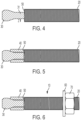
- An expansion part 30 is then welded to an end of the threaded rod 20 such that an axis 29 extending along the length of the expansion part 30 is parallel with an axis 21 extending along the length of the threaded rod 20, as illustrated by comparing Figs. 3 and 4 .
- the expansion part 30 has a conical expansion section 23 and a neck section 31.
- the expansion part 30 does not need to have a specific shape and the expansion section 23 can for example embody the shape of a known part such as the conical shaped expansion section in US patent number 7,857,564 .
- Welding of the expansion part 30 to the threaded rod 20 provides that an annular shoulder 50 is provided adjacent the interface between the expansion part 30 and the threaded rod 20.
- An expansion sleeve 40 is additionally provided around the expansion part 30 as shown in Fig. 5 which is caused to deform by movement of the conical expansion section 23 into the expansion sleeve 40 during use of the expansion anchor 10.
- a washer 60 and nut 70 can then be located on the threaded rod 20, whereby the anchor 10 formed can be subsequently used in the manner heretofore described.
- Various specific welding techniques are suitable for implementing the welding step including resistance welding or solid-state welding for example friction welding. It will be appreciated that ideally an end face 27 of the expansion part 30 and an end face 25 of the threaded rod 20 which engage during the welding process should be substantially flush with each other when brought into contact.
- An example suitable welding machine can be purchased from the company August Strecker GmbH & Co. KG with registered office at Jahnstrasse 5, D-65549 Limburg, Germany.
- the expansion part 30 is thinner than the threaded rod 20.
- the neck section 31 of the expansion part 30 has a smaller diameter than the major diameter of the threaded rod 20.
- the ratio of the major diameter of the threaded rod 20 to the neck section diameter can range from 1:0.5 to 1:0.9 for example and could be in particular 1:0.55, 1:0.77 or 1:0.89. This provides a gap denoted Z in Fig. 4 between the outer surface of the aforementioned neck section 31 and the top of the threads of the threaded rod 20.
- welding flash material comprising the weld connection between the expansion part 30 and the threaded rod 20, for instance excess weld material and/or melted sections of the expansion part 30 and the threaded rod 20
- welding flash does not protrude beyond the outer diameter of the expansion sleeve 40 which would otherwise have prevented the anchor 10 from being inserted into a hole in a concrete surface (bearing in mind that the diameter of a hole drilled into concrete is carefully controlled to closely correspond with the outer diameter of the expansion sleeve 40).
- the threaded rod 20 and expansion part 30 are formed from the same type of metal.
- they can both be formed of steel such as stainless steel or carbon steel.
- the expansion sleeve 40, the washer 60 and the nut 70 are also formed of metal and can additionally be made of the same type of metal as the other parts of the expansion anchor 10 or alternatively can be formed of a different type of metal to at least one of the threaded rod 20 and the expansion part 30.
- Expansion anchors can be made on demand to the specific lengths required by users, meaning optimised results will be realised in use (e.g. reduced excess length of threaded rod section protruding after a securing operation).
- the burden of inventory management is reduced in the sense that manufacturers do not need to predict how many anchors of different specific lengths will be required over the coming business period. In particular manufacturers no longer need to create X number of anchors of a first specific length and Y number of anchors of a second specific length, potentially resulting in too many or too few anchors being formed of a specific length. Instead anchors can be made to customised lengths on demand.
- a thicker anchor is required, a thicker threaded rod 20 (having a thicker minor diameter) will be welded to a thicker expansion part 30. If a thinner anchor is required, a thinner threaded rod 20 (having a thinner minor diameter) will be welded to a thinner expansion part 30.
- threaded rods of different specifications may be selected depending on the end application, in particular a manufacturer may stock multiple threaded rods of a particular thickness but each having a different thread pitch, thread height and/or thread profile. As such a threaded rod of the required thread specification will be used in manufacturing.
- FIG. 7 Another embodiment is described with reference to Fig. 7 , wherein all like components are denoted with similar reference numerals increased by 100.
- the weld is not located between the expansion part 130 and the threaded rod 120 at location B (like in the previous embodiment) but instead the weld is located at location A.
- the neck section of the expansion part 130 is integral with a rod-like spacer section 133 having a greater diameter than the neck section.
- the spacer section 133 has a diameter substantially equal to the major diameter or the minor diameter of the threaded rod 120.
- the annular shoulder 150 is formed at the location between the spacer section 133 and the neck section of the expansion part 130.
- the combination of the expansion part 130 (including the expansion section 123, neck section and spacer section 133) and the expansion sleeve 140 collectively comprise an expansion portion 135 which can be mass produced and welded to a threaded rod 120 having a pre-selected length and thread specification on demand.
- a threaded rod can be adapted, for example cut, to a predetermined length.
- An expansion portion 135 of the kind described in the foregoing paragraph is then welded to an end of the threaded rod 120 such that an axis extending along the length of the expansion portion 135 is parallel with an axis extending along the length of the threaded rod 120.
- the expansion portion 135 does not need to have a specific shape and can embody a known configuration of expansion section 123 and expansion sleeve 140.
- a washer 160 and nut 170 can then be located on the threaded rod 120, whereby the anchor 100 formed can be subsequently used in the manner heretofore described.
- welding flash material comprising the weld connection between the spacer section 133 and the threaded rod 120, for instance excess weld material and/or melted sections of the spacer section 133 and the threaded rod 120
- This additional manufacturing step can for example involve filing away unwanted welding flash.
- an expansion portion 135 of the kind heretofore described can be welded to a threaded rod 120, wherein the diameter of the spacer section 133 of the expansion portion 135 is less than the minor diameter of the threaded rod 120.
- an anchor having a gap (similar to the gap Z in Fig. 4 ) between the outer diameter of the spacer section 133 of the expansion portion 135 and the top of the threads of the threaded rod 120.
Landscapes
- Engineering & Computer Science (AREA)
- General Engineering & Computer Science (AREA)
- Mechanical Engineering (AREA)
- Dowels (AREA)
- Joining Of Building Structures In Genera (AREA)
Abstract
Description
- This specification concerns expansion anchors for securing objects to concrete.
- Expansion anchors are known in the art, for example
US patent number 7,857,564 . - An expansion anchor 1 in
Fig. 1 has a threadedrod 2, one end of which includes anexpansion feature 3 which is typically conical. Anexpansion sleeve 4 is provided between ashoulder 5 of the threadedrod 2 and theexpansion feature 3. In use the expansion anchor 1 is inserted through a hole in an object to be secured to a concrete surface. Theexpansion feature 3 is then fed into a hole in the concrete surface having a width similar to theexpansion sleeve 4. The expansion anchor 1 may need to be hit with a hammer to insert it into the hole because of friction arising between the concrete and theexpansion sleeve 4. Next awasher 6 andnut 7 are provided on the threadedrod 2 extending from the hole. Tightening thenut 7 causes it to ride along the threads of the threadedrod 2, which urges thewasher 6 against the object to be fixed and causes the threadedrod 2 to be pulled in a direction out of the hole. Since theexpansion sleeve 4 is maintained in place due to friction between it and the concrete, continued tightening of thenut 7 causes theexpansion element 3 to be drawn into theexpansion sleeve 4. Due to the conical shape of theexpansion element 3 this causes the expansion sleeve to deform and urge with increasing force against the concrete to increase pull-out strength of the expansion anchor 1. Eventually a configuration will result where the object is firmly clamped between the concrete surface and thewasher 6, the deformed expansion sleeve 4 firmly pressing against the interior surface of the hole so the expansion anchor 1 is secured to the concrete within acceptable limits of pull-out strength. - Different applications require different lengths of threaded
rod 2. For a particular object to be fixed to a concrete surface the threadedrod 2 of the expansion anchor 1 should not be too long or too short. If it is too long then even though the expansion sleeve 4 of the expansion anchor 1 is capable of reaching a minimum embedment depth in a hole, after the object has been suitably clamped to the concrete in the manner described there remains an excess length of threadedrod 2 protruding above the object. This can look unsightly, be unsafe for example if the object is clamped on the floor due to an increased risk of passers by tripping and can cause other problems, for example getting in the way of other fixtures on a building site thereby requiring the excess length of threadedrod 2 to be cut away which involves further steps but can also leave sharp edges behind which are also a safety concern. On the other hand, if the threadedrod 2 of an expansion anchor 1 is too short the anchor will simply not be long enough to be embedded to the aforementioned minimum embedment depth while leaving sufficient length of threadedrod 2 protruding above the object to be secured for thewasher 6 andnut 7 to be attached. - Construction companies or distributors must therefore stock expansion anchors 1 of different lengths in order to fix a range of objects of different thicknesses to concrete depending on the specific job at hand. It will be appreciated that inventory management involves a degree of prediction and so a company may inadvertently stock too many expansion anchors 1 of a particular length (because that length is not required as often as predicted) or too few expansion anchors 1 of a particular length (because that length is required more often than predicted, meaning that projects may undesirably be put on hold while new stock is ordered). If one or more companies overstocks on certain types of expansion anchors 1 it will be appreciated that this is not environmentally friendly since raw materials have been wasted making expansion anchors that are not being used and may not be so for quite some time.
- Aspects of the invention have been conceived with the foregoing in mind.
- According to an aspect of the invention there is provided a method according to claim 1, wherein optional steps thereof are defined in
claims 2 to 6. According to another aspect of the invention there is provided an expansion anchor according toclaim 7, wherein optional features thereof are defined in claim 8. - Various aspects and embodiments of the invention will now be described by way of non-limiting example with reference to the accompanying drawings, in which:
-
Fig. 1 is a partially cross-sectional illustration of a prior art expansion anchor; -
Fig. 2 illustrates a threaded rod; -
Fig. 3 illustrates a specific length of threaded rod adjacent an expansion part; -
Fig. 4 illustrates the threaded rod and expansion part welded together; -
Fig. 5 illustrates the arrangement inFig. 4 additionally with an expansion sleeve; -
Fig. 6 illustrates the arrangement inFig. 5 additionally with a washer and nut; and -
Fig. 7 illustrates a threaded rod according to another embodiment. - According to a method of forming an expansion anchor a threaded
rod 20 is provided as shown inFig. 2 , the rod having a thread along its outer surface. In a next step the threaded rod is adapted, for example cut, to a predetermined length. Anexpansion part 30 is then welded to an end of the threadedrod 20 such that anaxis 29 extending along the length of theexpansion part 30 is parallel with anaxis 21 extending along the length of the threadedrod 20, as illustrated by comparingFigs. 3 and4 . Theexpansion part 30 has aconical expansion section 23 and aneck section 31. Theexpansion part 30 does not need to have a specific shape and theexpansion section 23 can for example embody the shape of a known part such as the conical shaped expansion section inUS patent number 7,857,564 . Welding of theexpansion part 30 to the threadedrod 20 provides that anannular shoulder 50 is provided adjacent the interface between theexpansion part 30 and the threadedrod 20. Anexpansion sleeve 40 is additionally provided around theexpansion part 30 as shown inFig. 5 which is caused to deform by movement of theconical expansion section 23 into theexpansion sleeve 40 during use of theexpansion anchor 10. Persons skilled in the art will be familiar with suitable techniques for providing theexpansion sleeve 40 in place during manufacture. Awasher 60 andnut 70 can then be located on the threadedrod 20, whereby theanchor 10 formed can be subsequently used in the manner heretofore described. - Various specific welding techniques are suitable for implementing the welding step including resistance welding or solid-state welding for example friction welding. It will be appreciated that ideally an
end face 27 of theexpansion part 30 and anend face 25 of the threadedrod 20 which engage during the welding process should be substantially flush with each other when brought into contact. An example suitable welding machine can be purchased from the company August Strecker GmbH & Co. KG with registered office at Jahnstrasse 5, D-65549 Limburg, Germany. - In the method of forming an expansion anchor heretofore described, with reference to
Fig. 4 , at the interface between theexpansion part 30 and the adapted threadedrod 20 theexpansion part 30 is thinner than the threadedrod 20. In other words theneck section 31 of theexpansion part 30 has a smaller diameter than the major diameter of the threadedrod 20. In some embodiments the ratio of the major diameter of the threadedrod 20 to the neck section diameter can range from 1:0.5 to 1:0.9 for example and could be in particular 1:0.55, 1:0.77 or 1:0.89. This provides a gap denoted Z inFig. 4 between the outer surface of theaforementioned neck section 31 and the top of the threads of the threadedrod 20. This provides some flexibility during the manufacturing process in that welding flash (material comprising the weld connection between theexpansion part 30 and the threadedrod 20, for instance excess weld material and/or melted sections of theexpansion part 30 and the threaded rod 20) can occupy space within the gap denoted Z inFig. 4 and not protrude beyond the threads of the threadedrod 20. Therefore such welding flash does not protrude beyond the outer diameter of theexpansion sleeve 40 which would otherwise have prevented theanchor 10 from being inserted into a hole in a concrete surface (bearing in mind that the diameter of a hole drilled into concrete is carefully controlled to closely correspond with the outer diameter of the expansion sleeve 40). Excess welding flash protruding beyond the outer diameter of theexpansion sleeve 40 would need to be removed before ananchor 10 could be used. Keeping welding flash within the gap Z provides that after the welding step it is not necessary to perform an additional manufacturing step involving removing welding flash. - In some embodiments the threaded
rod 20 andexpansion part 30 are formed from the same type of metal. For example they can both be formed of steel such as stainless steel or carbon steel. - The expansion sleeve 40, the
washer 60 and thenut 70 are also formed of metal and can additionally be made of the same type of metal as the other parts of theexpansion anchor 10 or alternatively can be formed of a different type of metal to at least one of the threadedrod 20 and theexpansion part 30. - Techniques for forming the respective components heretofore described such as the threaded
rod 20, theexpansion part 30 and theexpansion sleeve 40 are known in the art, however, the inventor has not seen any instance where theexpansion part 30 of anexpansion anchor 10 is welded to a threadedrod section 20 of the anchor. - Forming expansion anchors according to the heretofore described method has multiple advantages. Expansion anchors can be made on demand to the specific lengths required by users, meaning optimised results will be realised in use (e.g. reduced excess length of threaded rod section protruding after a securing operation). The burden of inventory management is reduced in the sense that manufacturers do not need to predict how many anchors of different specific lengths will be required over the coming business period. In particular manufacturers no longer need to create X number of anchors of a first specific length and Y number of anchors of a second specific length, potentially resulting in too many or too few anchors being formed of a specific length. Instead anchors can be made to customised lengths on demand. In particular manufacturers can stock multiple
pre-made expansion parts 30 and weld them to customised lengths of threadedrod 20 on demand to form customised anchors 10. By extension it will be realised that this addresses the problem of improving environmental friendliness of the overall manufacturing process because it maximises the efficiency of raw material use and reduces the likelihood of manufactured anchors ultimately not being used and simply sitting in a stock room. - It will be realised from the foregoing that the teachings herein are applicable to different thicknesses of anchors. If a thicker anchor is required, a thicker threaded rod 20 (having a thicker minor diameter) will be welded to a
thicker expansion part 30. If a thinner anchor is required, a thinner threaded rod 20 (having a thinner minor diameter) will be welded to athinner expansion part 30. Furthermore, threaded rods of different specifications may be selected depending on the end application, in particular a manufacturer may stock multiple threaded rods of a particular thickness but each having a different thread pitch, thread height and/or thread profile. As such a threaded rod of the required thread specification will be used in manufacturing. - Another embodiment is described with reference to
Fig. 7 , wherein all like components are denoted with similar reference numerals increased by 100. In this embodiment the weld is not located between theexpansion part 130 and the threadedrod 120 at location B (like in the previous embodiment) but instead the weld is located at location A. In this embodiment therefore the neck section of theexpansion part 130 is integral with a rod-like spacer section 133 having a greater diameter than the neck section. Thespacer section 133 has a diameter substantially equal to the major diameter or the minor diameter of the threadedrod 120. Theannular shoulder 150 is formed at the location between thespacer section 133 and the neck section of theexpansion part 130. The combination of the expansion part 130 (including theexpansion section 123, neck section and spacer section 133) and theexpansion sleeve 140 collectively comprise anexpansion portion 135 which can be mass produced and welded to a threadedrod 120 having a pre-selected length and thread specification on demand. - According to a method of forming an expansion anchor 100 a threaded rod can be adapted, for example cut, to a predetermined length. An
expansion portion 135 of the kind described in the foregoing paragraph is then welded to an end of the threadedrod 120 such that an axis extending along the length of theexpansion portion 135 is parallel with an axis extending along the length of the threadedrod 120. Theexpansion portion 135 does not need to have a specific shape and can embody a known configuration ofexpansion section 123 andexpansion sleeve 140. Awasher 160 andnut 170 can then be located on the threadedrod 120, whereby theanchor 100 formed can be subsequently used in the manner heretofore described. - As with the previous embodiment various specific welding techniques are suitable for implementing the welding step including resistance welding or solid-state welding for example friction welding. It will be appreciated that ideally an end face of the
spacer section 133 and an end face of the threadedrod 120 which engage during the welding process should be substantially flush with each other when they are brought into contact. This embodiment however could potentially require the additional manufacturing step of removing welding flash (material comprising the weld connection between thespacer section 133 and the threadedrod 120, for instance excess weld material and/or melted sections of thespacer section 133 and the threaded rod 120) so that such welding flash does not protrude above the outer diameter of theexpansion sleeve 140 for reasons already explained. This additional manufacturing step can for example involve filing away unwanted welding flash. - According to a further embodiment an
expansion portion 135 of the kind heretofore described can be welded to a threadedrod 120, wherein the diameter of thespacer section 133 of theexpansion portion 135 is less than the minor diameter of the threadedrod 120. This results in an anchor having a gap (similar to the gap Z inFig. 4 ) between the outer diameter of thespacer section 133 of theexpansion portion 135 and the top of the threads of the threadedrod 120. Accordingly the advantages can be realised that were heretofore discussed in connection with the first embodiment, involving maintaining welding flash within the gap below the top of the threads and not needing to perform an additional manufacturing step removing excess material. - It will be appreciated that whilst various aspects and embodiments have heretofore been described, the scope of the present invention is not limited thereto and instead extends to encompass all methods and arrangements, and modifications and alterations thereto, which fall within the spirit and scope of the appended claims.
Claims (8)
- A method of making an expansion anchor comprising the steps of: providing a metal rod having a thread along at least part of its outer surface; cutting the metal rod to obtain a required length of metal rod (120); welding an expansion section (123) to an end of the obtained length of metal rod (120); and providing an expansion sleeve (140) which in use interacts with the expansion section (123) for increasing the expansion sleeve (140) diameter; wherein the expansion section (123) is integral with a spacer section (133) and the step of welding involves welding an end of the spacer section (133) to the threaded rod (120).
- The method of claim 1 wherein the expansion sleeve (140) is provided between the spacer section (133) and the expansion section (123) before the spacer section (133) is welded to the threaded rod (120).
- The method of claim 1 or 2 wherein the spacer section (133) has a diameter substantially equal to the major diameter or the minor diameter of the threaded rod (120).
- The method of any preceding claim wherein the step of welding involves electrical resistance welding.
- The method of any of claims 1 to 3 wherein the step of welding involves solid-state welding, optionally friction welding.
- The method of any preceding claim wherein at least one of the metal rod (120) and the expansion section (123) are formed of steel, optionally stainless steel or carbon steel.
- An expansion anchor comprising a threaded rod part (120), an expansion section (123) welded to an end of the rod part (120) and an expansion sleeve (140) which in use interacts with the expansion section (123) for increasing the diameter of the expansion sleeve (140), wherein the expansion section (123) is integral with a spacer section (133) and an end of the spacer section (133) is welded to the threaded rod (120) part.
- The anchor of claim 7 wherein the spacer section (133) has a diameter substantially equal to the major diameter or the minor diameter of the threaded rod (120).
Applications Claiming Priority (2)
| Application Number | Priority Date | Filing Date | Title |
|---|---|---|---|
| GB1912633.3A GB2586805A (en) | 2019-09-03 | 2019-09-03 | Expansion Anchor and method of making an expansion anchor |
| EP20190938.9A EP3789622B1 (en) | 2019-09-03 | 2020-08-13 | Expansion anchor and method of making an expansion anchor |
Related Parent Applications (2)
| Application Number | Title | Priority Date | Filing Date |
|---|---|---|---|
| EP20190938.9A Division EP3789622B1 (en) | 2019-09-03 | 2020-08-13 | Expansion anchor and method of making an expansion anchor |
| EP20190938.9A Division-Into EP3789622B1 (en) | 2019-09-03 | 2020-08-13 | Expansion anchor and method of making an expansion anchor |
Publications (3)
| Publication Number | Publication Date |
|---|---|
| EP4425003A2 true EP4425003A2 (en) | 2024-09-04 |
| EP4425003A3 EP4425003A3 (en) | 2024-11-13 |
| EP4425003B1 EP4425003B1 (en) | 2026-03-04 |
Family
ID=68206993
Family Applications (2)
| Application Number | Title | Priority Date | Filing Date |
|---|---|---|---|
| EP24190135.4A Active EP4425003B1 (en) | 2019-09-03 | 2020-08-13 | Expansion anchor and method of making an expansion anchor |
| EP20190938.9A Active EP3789622B1 (en) | 2019-09-03 | 2020-08-13 | Expansion anchor and method of making an expansion anchor |
Family Applications After (1)
| Application Number | Title | Priority Date | Filing Date |
|---|---|---|---|
| EP20190938.9A Active EP3789622B1 (en) | 2019-09-03 | 2020-08-13 | Expansion anchor and method of making an expansion anchor |
Country Status (3)
| Country | Link |
|---|---|
| US (1) | US11572912B2 (en) |
| EP (2) | EP4425003B1 (en) |
| GB (1) | GB2586805A (en) |
Families Citing this family (1)
| Publication number | Priority date | Publication date | Assignee | Title |
|---|---|---|---|---|
| DE102023121172A1 (en) * | 2023-08-09 | 2025-02-13 | Fischerwerke Gmbh & Co. Kg | modular system with multiple fasteners |
Citations (1)
| Publication number | Priority date | Publication date | Assignee | Title |
|---|---|---|---|---|
| US7857564B2 (en) | 2006-08-23 | 2010-12-28 | Hilti Aktiengesellschaft | Expansion dowel |
Family Cites Families (10)
| Publication number | Priority date | Publication date | Assignee | Title |
|---|---|---|---|---|
| US2377077A (en) * | 1943-07-24 | 1945-05-29 | Gay Bert | Expansion nut |
| GB1466917A (en) * | 1970-05-27 | 1977-03-09 | Rawlplug Co Ltd | Bolt anchor |
| DE2809644A1 (en) * | 1978-03-06 | 1979-09-20 | Hilti Ag | DOWELS FOR FIXING TO CAVITIES |
| EP0279936B1 (en) | 1987-02-21 | 1990-10-03 | fischerwerke Artur Fischer GmbH & Co. KG | Dowel with an expansion sleeve |
| JP2004116128A (en) * | 2002-09-26 | 2004-04-15 | Sanko Techno Co Ltd | Concrete structure jointing material |
| GB2491805B (en) * | 2011-05-12 | 2015-07-08 | Tension Control Bolts Ltd | Fastening assembly |
| FR2992697B1 (en) * | 2012-06-28 | 2015-01-02 | Saint Gobain Placo | EXPANSION ANKLE |
| EP3564540A1 (en) * | 2018-05-03 | 2019-11-06 | HILTI Aktiengesellschaft | Expansion anchor with protected optical code |
| EP3584453A1 (en) * | 2018-06-20 | 2019-12-25 | HILTI Aktiengesellschaft | Expansion anchor with a nonaxisymmetric recess |
| CN108679061A (en) * | 2018-07-01 | 2018-10-19 | 沈阳建筑大学 | The expansion bolt and its installation method of double expansion-heads |
-
2019
- 2019-09-03 GB GB1912633.3A patent/GB2586805A/en not_active Withdrawn
-
2020
- 2020-08-13 EP EP24190135.4A patent/EP4425003B1/en active Active
- 2020-08-13 EP EP20190938.9A patent/EP3789622B1/en active Active
- 2020-09-01 US US17/009,209 patent/US11572912B2/en active Active
Patent Citations (1)
| Publication number | Priority date | Publication date | Assignee | Title |
|---|---|---|---|---|
| US7857564B2 (en) | 2006-08-23 | 2010-12-28 | Hilti Aktiengesellschaft | Expansion dowel |
Also Published As
| Publication number | Publication date |
|---|---|
| EP4425003B1 (en) | 2026-03-04 |
| US11572912B2 (en) | 2023-02-07 |
| US20210062845A1 (en) | 2021-03-04 |
| GB2586805A (en) | 2021-03-10 |
| EP3789622B1 (en) | 2025-06-11 |
| GB201912633D0 (en) | 2019-10-16 |
| EP4425003A3 (en) | 2024-11-13 |
| EP3789622A1 (en) | 2021-03-10 |
Similar Documents
| Publication | Publication Date | Title |
|---|---|---|
| DK3060816T3 (en) | Expansion anchor with expansion sleeve with high strength sections | |
| CN109963992B (en) | Coupling apparatus, related components, and methods of use thereof | |
| JP6216072B2 (en) | Expansion anchor | |
| EP1455970B1 (en) | Method of fastening | |
| JP7846814B2 (en) | Multi-piece fastener, multi-piece fastener installation device, and fastening method | |
| CN108138827A (en) | Thread forming screw with independent thread helix and different flank angles | |
| CN110805597B (en) | Expansion anchor bolt | |
| EP0595966A4 (en) | A cable bolt | |
| US20160327081A1 (en) | Screw, fastening arrangement and use of a screw | |
| JP2015501403A (en) | Anchor rod | |
| EP4425003B1 (en) | Expansion anchor and method of making an expansion anchor | |
| US20200108475A1 (en) | Press-in connecting element and method for anchoring press-in connecting elements in a permanently deformable flat metal material or components or workpieces produced therefrom | |
| AU2014349209B2 (en) | Expanding wall anchor and use for fixing a component to a support material | |
| EP2691659B1 (en) | Fastening anchor and fastening device | |
| AU2014349209A1 (en) | Expanding wall anchor and use for fixing a component to a support material | |
| JP7183439B2 (en) | Blind fasteners and their installation methods | |
| WO2007112481A1 (en) | A yielding rock bolt | |
| US20190154072A1 (en) | Screw anchors and manufacturing methods | |
| RU2653035C2 (en) | Method of producing steel pipe | |
| AU2017101859B4 (en) | Removable Anchor Bolt Assembly and Method | |
| JP7309226B2 (en) | blind nut | |
| AU668515B2 (en) | A cable bolt | |
| CN106089891B (en) | Connection anchor and connection anchor system | |
| WO2007147196A1 (en) | Thread forming wire thread insert | |
| US20220128077A1 (en) | Blind fasteners and methods of fastening |
Legal Events
| Date | Code | Title | Description |
|---|---|---|---|
| PUAI | Public reference made under article 153(3) epc to a published international application that has entered the european phase |
Free format text: ORIGINAL CODE: 0009012 |
|
| STAA | Information on the status of an ep patent application or granted ep patent |
Free format text: STATUS: THE APPLICATION HAS BEEN PUBLISHED |
|
| AC | Divisional application: reference to earlier application |
Ref document number: 3789622 Country of ref document: EP Kind code of ref document: P |
|
| AK | Designated contracting states |
Kind code of ref document: A2 Designated state(s): AL AT BE BG CH CY CZ DE DK EE ES FI FR GB GR HR HU IE IS IT LI LT LU LV MC MK MT NL NO PL PT RO RS SE SI SK SM TR |
|
| PUAL | Search report despatched |
Free format text: ORIGINAL CODE: 0009013 |
|
| AK | Designated contracting states |
Kind code of ref document: A3 Designated state(s): AL AT BE BG CH CY CZ DE DK EE ES FI FR GB GR HR HU IE IS IT LI LT LU LV MC MK MT NL NO PL PT RO RS SE SI SK SM TR |
|
| RIC1 | Information provided on ipc code assigned before grant |
Ipc: F16B 13/06 20060101AFI20241010BHEP |
|
| STAA | Information on the status of an ep patent application or granted ep patent |
Free format text: STATUS: REQUEST FOR EXAMINATION WAS MADE |
|
| 17P | Request for examination filed |
Effective date: 20250506 |
|
| GRAP | Despatch of communication of intention to grant a patent |
Free format text: ORIGINAL CODE: EPIDOSNIGR1 |
|
| STAA | Information on the status of an ep patent application or granted ep patent |
Free format text: STATUS: GRANT OF PATENT IS INTENDED |
|
| INTG | Intention to grant announced |
Effective date: 20251024 |
|
| GRAS | Grant fee paid |
Free format text: ORIGINAL CODE: EPIDOSNIGR3 |
|
| P01 | Opt-out of the competence of the unified patent court (upc) registered |
Free format text: CASE NUMBER: UPC_APP_0019139_4425003/2025 Effective date: 20251222 |
|
| GRAA | (expected) grant |
Free format text: ORIGINAL CODE: 0009210 |
|
| STAA | Information on the status of an ep patent application or granted ep patent |
Free format text: STATUS: THE PATENT HAS BEEN GRANTED |
|
| AC | Divisional application: reference to earlier application |
Ref document number: 3789622 Country of ref document: EP Kind code of ref document: P |
|
| AK | Designated contracting states |
Kind code of ref document: B1 Designated state(s): AL AT BE BG CH CY CZ DE DK EE ES FI FR GB GR HR HU IE IS IT LI LT LU LV MC MK MT NL NO PL PT RO RS SE SI SK SM TR |
|
| REG | Reference to a national code |
Ref country code: CH Ref legal event code: F10 Free format text: ST27 STATUS EVENT CODE: U-0-0-F10-F00 (AS PROVIDED BY THE NATIONAL OFFICE) Effective date: 20260304 Ref country code: GB Ref legal event code: FG4D |
|
| REG | Reference to a national code |
Ref country code: IE Ref legal event code: FG4D |
|
| REG | Reference to a national code |
Ref country code: DE Ref legal event code: R096 Ref document number: 602020068279 Country of ref document: DE |