EP4424996A1 - Rotary compressor - Google Patents
Rotary compressor Download PDFInfo
- Publication number
- EP4424996A1 EP4424996A1 EP23811735.2A EP23811735A EP4424996A1 EP 4424996 A1 EP4424996 A1 EP 4424996A1 EP 23811735 A EP23811735 A EP 23811735A EP 4424996 A1 EP4424996 A1 EP 4424996A1
- Authority
- EP
- European Patent Office
- Prior art keywords
- housing
- compression unit
- leg
- rotary compressor
- circumferential direction
- Prior art date
- Legal status (The legal status is an assumption and is not a legal conclusion. Google has not performed a legal analysis and makes no representation as to the accuracy of the status listed.)
- Granted
Links
Images




Classifications
-
- F—MECHANICAL ENGINEERING; LIGHTING; HEATING; WEAPONS; BLASTING
- F04—POSITIVE - DISPLACEMENT MACHINES FOR LIQUIDS; PUMPS FOR LIQUIDS OR ELASTIC FLUIDS
- F04C—ROTARY-PISTON, OR OSCILLATING-PISTON, POSITIVE-DISPLACEMENT MACHINES FOR LIQUIDS; ROTARY-PISTON, OR OSCILLATING-PISTON, POSITIVE-DISPLACEMENT PUMPS
- F04C23/00—Combinations of two or more pumps, each being of rotary-piston or oscillating-piston type, specially adapted for elastic fluids; Pumping installations specially adapted for elastic fluids; Multi-stage pumps specially adapted for elastic fluids
- F04C23/008—Hermetic pumps
-
- F—MECHANICAL ENGINEERING; LIGHTING; HEATING; WEAPONS; BLASTING
- F01—MACHINES OR ENGINES IN GENERAL; ENGINE PLANTS IN GENERAL; STEAM ENGINES
- F01C—ROTARY-PISTON OR OSCILLATING-PISTON MACHINES OR ENGINES
- F01C21/00—Component parts, details or accessories not provided for in groups F01C1/00 - F01C20/00
- F01C21/10—Outer members for co-operation with rotary pistons; Casings
-
- F—MECHANICAL ENGINEERING; LIGHTING; HEATING; WEAPONS; BLASTING
- F04—POSITIVE - DISPLACEMENT MACHINES FOR LIQUIDS; PUMPS FOR LIQUIDS OR ELASTIC FLUIDS
- F04C—ROTARY-PISTON, OR OSCILLATING-PISTON, POSITIVE-DISPLACEMENT MACHINES FOR LIQUIDS; ROTARY-PISTON, OR OSCILLATING-PISTON, POSITIVE-DISPLACEMENT PUMPS
- F04C18/00—Rotary-piston pumps specially adapted for elastic fluids
- F04C18/30—Rotary-piston pumps specially adapted for elastic fluids having the characteristics covered by two or more of groups F04C18/02, F04C18/08, F04C18/22, F04C18/24, F04C18/48, or having the characteristics covered by one of these groups together with some other type of movement between co-operating members
- F04C18/34—Rotary-piston pumps specially adapted for elastic fluids having the characteristics covered by two or more of groups F04C18/02, F04C18/08, F04C18/22, F04C18/24, F04C18/48, or having the characteristics covered by one of these groups together with some other type of movement between co-operating members having the movement defined in group F04C18/08 or F04C18/22 and relative reciprocation between the co-operating members
- F04C18/356—Rotary-piston pumps specially adapted for elastic fluids having the characteristics covered by two or more of groups F04C18/02, F04C18/08, F04C18/22, F04C18/24, F04C18/48, or having the characteristics covered by one of these groups together with some other type of movement between co-operating members having the movement defined in group F04C18/08 or F04C18/22 and relative reciprocation between the co-operating members with vanes reciprocating with respect to the outer member
-
- F—MECHANICAL ENGINEERING; LIGHTING; HEATING; WEAPONS; BLASTING
- F04—POSITIVE - DISPLACEMENT MACHINES FOR LIQUIDS; PUMPS FOR LIQUIDS OR ELASTIC FLUIDS
- F04C—ROTARY-PISTON, OR OSCILLATING-PISTON, POSITIVE-DISPLACEMENT MACHINES FOR LIQUIDS; ROTARY-PISTON, OR OSCILLATING-PISTON, POSITIVE-DISPLACEMENT PUMPS
- F04C2230/00—Manufacture
- F04C2230/20—Manufacture essentially without removing material
- F04C2230/23—Manufacture essentially without removing material by permanently joining parts together
- F04C2230/231—Manufacture essentially without removing material by permanently joining parts together by welding
-
- F—MECHANICAL ENGINEERING; LIGHTING; HEATING; WEAPONS; BLASTING
- F04—POSITIVE - DISPLACEMENT MACHINES FOR LIQUIDS; PUMPS FOR LIQUIDS OR ELASTIC FLUIDS
- F04C—ROTARY-PISTON, OR OSCILLATING-PISTON, POSITIVE-DISPLACEMENT MACHINES FOR LIQUIDS; ROTARY-PISTON, OR OSCILLATING-PISTON, POSITIVE-DISPLACEMENT PUMPS
- F04C2240/00—Components
- F04C2240/30—Casings or housings
-
- F—MECHANICAL ENGINEERING; LIGHTING; HEATING; WEAPONS; BLASTING
- F04—POSITIVE - DISPLACEMENT MACHINES FOR LIQUIDS; PUMPS FOR LIQUIDS OR ELASTIC FLUIDS
- F04C—ROTARY-PISTON, OR OSCILLATING-PISTON, POSITIVE-DISPLACEMENT MACHINES FOR LIQUIDS; ROTARY-PISTON, OR OSCILLATING-PISTON, POSITIVE-DISPLACEMENT PUMPS
- F04C2240/00—Components
- F04C2240/80—Other components
- F04C2240/805—Fastening means, e.g. bolts
-
- F—MECHANICAL ENGINEERING; LIGHTING; HEATING; WEAPONS; BLASTING
- F04—POSITIVE - DISPLACEMENT MACHINES FOR LIQUIDS; PUMPS FOR LIQUIDS OR ELASTIC FLUIDS
- F04C—ROTARY-PISTON, OR OSCILLATING-PISTON, POSITIVE-DISPLACEMENT MACHINES FOR LIQUIDS; ROTARY-PISTON, OR OSCILLATING-PISTON, POSITIVE-DISPLACEMENT PUMPS
- F04C2270/00—Control; Monitoring or safety arrangements
- F04C2270/12—Vibration
Definitions
- the present disclosure relates to a rotary compressor.
- a rotary compressor is one type of compressor used in devices such as refrigeration devices and air-conditioning devices (e.g., Patent Document 1).
- Patent Document 1 JP 58-131392 A
- the vibration causes a refrigerant pipe to break
- the refrigerant inside the pipe may leak to the outside.
- a flammable refrigerant (A2L or A3 as an example of the class)
- A2L or A3 as an example of the class there is a higher need to help prevent the refrigerant from leaking.
- the present disclosure has been made in view of such circumstances, and it is an object of the present disclosure to provide a rotary compressor that can reduce vibration during driving.
- a rotary compressor including a housing including a tubular portion extending in a height direction along an axis, a compression unit that is accommodated in the housing and fixed to the tubular portion by a plurality of welded portions formed in a circumferential direction about the axis, the compression unit being configured to compress a refrigerant, a drive unit accommodated in the housing and being configured to drive the compression unit, and a plurality of leg portions provided on an outside surface of the tubular portion and being configured to fix the housing to an installation surface, in which positions of the leg portions correspond to positions of the welded portions in the circumferential direction, respectively.
- a rotary compressor (hereinafter simply referred to as a "compressor") 1 according to the present embodiment is a hermetically sealed electric rotary compressor used in, for example, an air conditioner or a refrigeration device.
- the compressor 1 has a weight of 6.5 kg or less and includes a compressor main body 10 and an accumulator 12.
- the accumulator 12 is coupled to the compressor main body 10 via a suction tube 11.
- the compressor main body 10 includes a housing 2 having a substantially cylindrical shape, a rotor shaft body 3, an electric motor (drive unit) 5, and a rotary compression unit (compression unit) 6.
- An axis of rotation CL1 of the rotor shaft body 3 coincides with a center axis CL2 of the housing 2.
- the rotor shaft body 3 is disposed extending in an up-down direction and rotates about the axis of rotation CL1 in the housing 2.
- the housing 2 is hermetically sealed and extends in the up-down direction.
- the up-down direction coincides with, for example, a height direction of the housing 2 when the compressor 1 is installed on an installation surface FL (see FIG. 3 ).
- the housing 2 includes a tubular portion 21 extending in the height direction along the center axis CL2, and an upper lid portion 22 and a lower lid portion 23 that close upper and lower openings of the tubular portion 21, respectively.
- the outer diameter of the tubular portion 21 is, for example, 95 mm or less.
- a plurality of leg portions 7 are fixed to an outside surface 21b of the tubular portion 21 at a lower portion.
- the leg portions 7 are disposed in the circumferential direction at predetermined angular intervals.
- three leg portions 7 are disposed at intervals of about 120 degrees in the circumferential direction.
- FIG. 2 some components (e.g., detailed portions of the accumulator 12, the upper lid portion 22, the rotor shaft body 3, and an upper bearing 4A) are not illustrated to simplify the description.
- the compressor 1 is installed by each leg portion 7 being fixed to the installation surface FL via vibration-proof rubber 8.
- an opening 24 is formed in a lower portion of the side wall of the housing 2 at a position facing the outside surface of a cylinder 60.
- a suction port 25 that communicates with a predetermined position in the cylinder is formed at a position facing the opening 24.
- An oil sump for storing lubricating oil is formed at a bottom portion of the housing 2.
- the liquid level in the oil sump when the oil sump is initially sealed is located above the rotary compression unit 6.
- the rotary compression unit 6 is driven in the oil sump.
- the upper lid portion 22 is provided with a discharge tube 13 and a terminal block 30.
- the discharge tube 13 extends through the upper lid portion 22 in a thickness direction and includes a lower portion disposed inside the housing 2 and an upper portion disposed outside the housing 2.
- the discharge tube 13 discharges a compressed refrigerant to the outside of the housing 2.
- the terminal block 30 is provided with three power supply terminals 31 for supplying electric power to the electric motor 5. Three-phase alternating electric power is supplied to the power supply terminals 31 from an inverter device (not illustrated).
- the accumulator 12 is used to separate a refrigerant into gas and liquid before the refrigerant is supplied to the compressor main body 10.
- the accumulator 12 has a substantially cylindrical shape and is fixed to the housing 2 (the outside surface 21b of the tubular portion 21) via a bracket 14.
- An inlet tube 15 for introducing the refrigerant guided from an evaporator (not illustrated) is provided at an upper portion of the accumulator 12.
- the suction tube 11 for causing the refrigerant inside the accumulator 12 to be sucked into the compressor main body 10 is coupled to the accumulator 12.
- the suction tube 11 is coupled to the suction port 25 through the opening 24 of the housing 2.
- the accumulator 12 supplies the gas-phase refrigerant to the rotary compression unit 6 through the suction tube 11.
- the electric motor 5 is accommodated at a central portion of the housing 2 in the up-down direction.
- the electric motor 5 includes a rotor 51 and a stator 52.
- the rotor 51 is fixed to the outside surface of the rotor shaft body 3 and is disposed above the rotary compression unit 6.
- the stator 52 is disposed surrounding the outside surface of the rotor 51 and is fixed (e.g., shrink fitted) to an inside surface 21a of the tubular portion 21 of the housing 2. Electric power is supplied to the stator 52 from each power supply terminal 31 through a wiring line 32.
- the electric motor 5 is configured such that the rotor 51 rotates by the electric power supplied from the power supply terminal 31.
- the rotor shaft body 3 is rotationally driven about the axis of rotation CL1. At this time, the rotation of the electric motor 5 is vector-controlled.
- the rotary compression unit 6 includes a cylinder 60 and an upper bearing 4A and a lower bearing 4B.
- the rotary compression unit 6 is disposed at a lower portion (bottom portion) in the up-down direction in the housing 2 with the cylinder 60 sandwiched between the upper bearing 4A and the lower bearing 4B from above and below.
- the upper bearing 4A and the lower bearing 4B are each made of a metal material and are fixed by the cylinder 60 and a bolt 61.
- the rotor shaft body 3 is rotatably supported by the upper bearing 4A and the lower bearing 4B about the axis of rotation CL1.
- the rotary compression unit 6 further includes an eccentric shaft portion 62 and a piston rotor 63 provided around the eccentric shaft portion 62.
- the eccentric shaft portion 62 is formed at a lower portion of the rotor shaft body 3 and is provided in a space formed by the inside surface of the piston rotor 63 in a state of being offset in a direction orthogonal to the axis of rotation CL1 of the rotor shaft body 3.
- the piston rotor 63 has a cylindrical shape having an outside diameter smaller than the inside diameter of the cylinder 60.
- the piston rotor 63 is disposed in a space formed by the inside surface of the cylinder 60 and is fixed in a state of being mounted at the outside surface of the eccentric shaft portion 62.
- the piston rotor 63 eccentrically rotates about the axis of rotation CL1 along with the rotation of the rotor shaft body 3.
- a compression chamber 60A, a suction hole 60B, and a discharge hole (not illustrated) are formed in the rotary compression unit 6.
- the space formed by the inside surface of the cylinder 60 is sandwiched between the upper bearing 4A and the lower bearing 4B to define the compression chamber 60A.
- the piston rotor 63 is accommodated in the compression chamber 60A.
- the suction hole 60B is a hole for guiding the refrigerant to the compression chamber 60A from the outside of the cylinder 60 and is formed in the cylinder 60 along a direction orthogonal to the axis of rotation CL1.
- the rotary compression unit 6 configured as described above is fixed to the housing 2. Specifically, as illustrated in FIGS. 1 and 2 , for example, the upper bearing 4A is fixed by being plug-welded at a plurality of locations in the circumferential direction of the tubular portion 21.
- the upper bearing 4A is fixed to the housing 2 by a welded portion 70 formed extending from the outside surface 21b of the tubular portion 21 to the upper bearing 4A through the tubular portion 21.
- the welded portion 70 is a fixing portion between the housing 2 and the rotary compression unit 6, and is also an excitation position (excitation source) that transmits vibration and mechanical reaction force from the rotary compression unit 6 to the housing 2.
- the positions of the welded portions 70 are preferably disposed at equal angular intervals in the circumferential direction from the viewpoint of force balance.
- three welded portions 70 are formed at intervals of about 120 degrees in the circumferential direction.
- welded portions 70 is not limited to three and may be four or more, for example.
- the welded portion 70 may be formed in the cylinder 60 instead of the upper bearing 4A. That is, the cylinder 60 may be plug-welded to the tubular portion 21.
- the compressor 1 configured as described above operates as follows. A refrigerant guided from the evaporator (not illustrated) is taken into the accumulator 12 through the inlet tube 15.
- the refrigerant is separated into gas and liquid in the accumulator 12, and the gas-phase refrigerant is guided to the rotary compression unit 6 through the suction tube 11.
- the refrigerant is guided to the compression chamber 60A through the suction hole 60B.
- eccentric rotation of the piston rotor 63 gradually decreases the volume of the compression chamber 60A and compresses the refrigerant.
- the refrigerant after compression is guided into a space formed between a discharge cover 65 and the upper bearing 4A through a discharge hole (not illustrated) formed in the cylinder 60 and then discharged into the space inside the housing 2.
- the refrigerant discharged into the space inside the housing 2 is guided to a condenser (not illustrated) through the discharge tube 13 provided at the upper portion of the housing 2.
- the positions of the leg portions 7 correspond to the positions of the welded portions 70 in the circumferential direction with respect to the center axis CL2.
- the leg portion 7 is disposed such that the line L2 falls within a range of ⁇ 10 degrees with respect to the line L1 as a reference, with the center axis CL2 as the center of the angle.
- leg portion 7 is disposed such that the line L2 coincides with the line L1.
- the position of the leg portion 7 preferably corresponds to the position of the rotary compression unit 6 in the height direction of the tubular portion 21.
- leg portion 7 overlaps any component constituting the rotary compression unit 6 in the height direction.
- leg portion 7 overlaps the lower bearing 4B constituting the rotary compression unit 6 in the height direction.
- the reaction force at the welded portion 70 is received by the leg portion 7.
- the torsion of the tubular portion 21 (housing 2) can be reduced and a decrease in controllability due to the relative phase shift between the stator 52 and the rotor 51 can be suppressed.
- a force in the circumferential direction originating from the reaction force at the welded portion 70 acts on the tubular portion 21 by driving the rotary compression unit 6.
- a force in the circumferential direction originating from the torque reaction force received by the stator 52 due to the rotation of the electric motor 5 acts on the tubular portion 21 to which the stator 52 is fixed.
- the leg portion 7 When the position of the leg portion 7 corresponds to the position of the rotary compression unit 6 in the height direction, the leg portion 7 can be brought further closer to the welded portion 70 being the excitation position. Accordingly, the reaction force at the welded portion 70 is more likely to be received at the leg portion 7.
- the leg portion 7 When the center position of the leg portion 7 in the circumferential direction coincides with the center position of the welded portion 70 in the circumferential direction, the leg portion 7 can be brought closest to the welded portion 70 being the excitation position. Accordingly, the reaction force at the welded portion 70 is more likely to be received at the leg portion 7.
- the reaction force at the welded portions 70 can be processed in a well-balanced manner.
- a support leg portion 9 may be provided between one leg portion 7 corresponding to the position of the welded portion 70 and the leg portion 7 adjacent thereto (preferably at an intermediate position).
- the support leg portions 9 are provided at predetermined angular intervals in the circumferential direction on the outside surface 21b at the lower portion of the tubular portion 21.
- the support leg portion 9 is provided at the same height position as the leg portion 7.
- the support leg portion 9 is fixed to the installation surface FL via the vibration-proof rubber 8.
- a rotary compressor includes a housing (2) including a tubular portion (21) extending in a height direction along an axis (CL2), a compression unit (6) that is accommodated in the housing and fixed to the tubular portion by a plurality of welded portions (70) formed in a circumferential direction about the axis, the compression unit being configured to compress a refrigerant, a drive unit (5) accommodated in the housing and being configured to drive the compression unit, and a plurality of leg portions (7) provided on an outside surface (21b) of the tubular portion and being configured to fix the housing to an installation surface (FL), in which positions of the leg portions correspond to positions of the welded portions in the circumferential direction, respectively.
- a housing (2) including a tubular portion (21) extending in a height direction along an axis (CL2), a compression unit (6) that is accommodated in the housing and fixed to the tubular portion by a plurality of welded portions (70) formed in a circumferential direction about the axis, the compression unit
- the rotary compressor according to the present aspect includes a housing including a tubular portion extending in a height direction along an axis, a compression unit that is accommodated in the housing and fixed to the tubular portion by a plurality of welded portions formed in a circumferential direction about the axis, the compression unit being configured to compress a refrigerant, a drive unit accommodated in the housing and being configured to drive the compression unit, and a plurality of leg portions provided on an outside surface of the tubular portion and being configured to fix the housing to an installation surface. Positions of the leg portions correspond to positions of the welded portions in the circumferential direction, respectively.
- leg portions receive the reaction force, torsion of the tubular portion (housing) caused by the reaction force can be reduced. Therefore, it is possible to help prevent failure of the drive unit caused by the torsion of the tubular portion (housing) (e.g., a decrease in controllability caused by a relative phase shift between the stator and the rotor when the drive unit is an electric motor).
- a rotary compressor according to a second aspect of the present disclosure is the rotary compressor according to the first aspect, in which the drive unit is an electric motor (5) including a stator (52) fixed to the housing and a rotor (51) connected to the compression unit.
- the drive unit is an electric motor (5) including a stator (52) fixed to the housing and a rotor (51) connected to the compression unit.
- the drive unit is an electric motor including the stator fixed to the housing and the rotor connected to the compression unit
- the reaction force at the welded portion as a connecting location with the compression unit is received by the leg portions.
- torsion of the tubular portion (housing) caused by the reaction force at the welded portion and the torque reaction force received by the stator can be reduced and a decrease in controllability due to the relative phase shift between the stator and the rotor can be suppressed.
- a rotary compressor according to a third aspect of the present disclosure is the rotary compressor according to the first aspect or the second aspect, in which the position of each of the leg portions corresponds to a position of the compression unit in the height direction.
- the leg portion since the position of the leg portion corresponds to the position of the compression unit in the height direction, the leg portion can be brought further closer to the welded portion being the excitation position. Accordingly, the reaction force at the welded portion is more likely to be received at the leg portion.
- a rotary compressor according to a fourth aspect of the present disclosure is the rotary compressor according to any one of the first to third aspects, in which center positions of the leg portions in the circumferential direction coincide with center positions of the welded portions in the circumferential direction, respectively.
- the leg portion in the circumferential direction coincides with the center position of the welded portion in the circumferential direction, the leg portion can be brought closest to the welded portion being the excitation position. Accordingly, the reaction force at the welded portion is more likely to be received at the leg portion.
- a rotary compressor according to a fifth aspect of the present disclosure is the rotary compressor according to any one of the first to fourth aspects, in which the welded portions and the leg portions are disposed at substantially equal angular intervals in the circumferential direction.
- the welded portions and the leg portions are disposed at substantially equal angular intervals in the circumferential direction, it is possible to process the reaction force in the welded portions in a well-balanced manner.
- a rotary compressor according to a sixth aspect of the present disclosure is the rotary compressor according to any one of the first to fifth aspects, further including a support leg portion (9) provided on the outside surface of the tubular portion between one leg portion of the leg portions and another leg portion of the leg portions adjacent to the one leg portion.
- the support leg portion is provided on the outside surface of the tubular portion between one leg portion of the leg portions and another leg portion of the leg portions adjacent to the one leg portion.
Landscapes
- Engineering & Computer Science (AREA)
- Mechanical Engineering (AREA)
- General Engineering & Computer Science (AREA)
- Applications Or Details Of Rotary Compressors (AREA)
- Compressor (AREA)
Abstract
Description
- The present disclosure relates to a rotary compressor.
- A rotary compressor is one type of compressor used in devices such as refrigeration devices and air-conditioning devices (e.g., Patent Document 1).
- In a related-art rotary compressor having a relatively large weight, the weight of the rotary compressor tends to suppress vibration caused by driving a compression unit (e.g., piston rotor rotation). However, as rotary compressors have become lighter, problems related to vibration have become more apparent.
- Patent Document 1:
JP 58-131392 A - When vibration occurs, ease of mounting the compressor to a product may be impaired.
- If the vibration causes a refrigerant pipe to break, the refrigerant inside the pipe may leak to the outside. In particular, when a flammable refrigerant (A2L or A3 as an example of the class) is used as the refrigerant, there is a higher need to help prevent the refrigerant from leaking.
- The present disclosure has been made in view of such circumstances, and it is an object of the present disclosure to provide a rotary compressor that can reduce vibration during driving.
- To solve the above problem, the present disclosure provides a rotary compressor including a housing including a tubular portion extending in a height direction along an axis, a compression unit that is accommodated in the housing and fixed to the tubular portion by a plurality of welded portions formed in a circumferential direction about the axis, the compression unit being configured to compress a refrigerant, a drive unit accommodated in the housing and being configured to drive the compression unit, and a plurality of leg portions provided on an outside surface of the tubular portion and being configured to fix the housing to an installation surface, in which positions of the leg portions correspond to positions of the welded portions in the circumferential direction, respectively.
- According to the rotary compressor of the present disclosure, it is possible to reduce vibration during driving.
-
-
FIG. 1 is a vertical cross-sectional view illustrating a rotary compressor according to an embodiment of the present disclosure. -
FIG. 2 is a plan view illustrating the rotary compressor according to the embodiment of the present disclosure. -
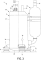
FIG. 3 is a side view illustrating a state in which the rotary compressor ofFIG. 1 is provided on an installation surface. -
FIG. 4 is a partially enlarged view of a portion A illustrated inFIG. 1 . -
FIG. 5 is a plan view illustrating a modification example of the rotary compressor according to the embodiment of the present disclosure. - An embodiment according to the present disclosure will be described below with reference to the drawings.
- As illustrated in
FIG. 1 , a rotary compressor (hereinafter simply referred to as a "compressor") 1 according to the present embodiment is a hermetically sealed electric rotary compressor used in, for example, an air conditioner or a refrigeration device. The compressor 1 has a weight of 6.5 kg or less and includes a compressormain body 10 and anaccumulator 12. Theaccumulator 12 is coupled to the compressormain body 10 via asuction tube 11. - The compressor
main body 10 includes ahousing 2 having a substantially cylindrical shape, arotor shaft body 3, an electric motor (drive unit) 5, and a rotary compression unit (compression unit) 6. - An axis of rotation CL1 of the
rotor shaft body 3 coincides with a center axis CL2 of thehousing 2. - The
rotor shaft body 3 is disposed extending in an up-down direction and rotates about the axis of rotation CL1 in thehousing 2. - The
housing 2 is hermetically sealed and extends in the up-down direction. The up-down direction coincides with, for example, a height direction of thehousing 2 when the compressor 1 is installed on an installation surface FL (seeFIG. 3 ). - The
housing 2 includes atubular portion 21 extending in the height direction along the center axis CL2, and anupper lid portion 22 and alower lid portion 23 that close upper and lower openings of thetubular portion 21, respectively. The outer diameter of thetubular portion 21 is, for example, 95 mm or less. - A plurality of
leg portions 7 are fixed to anoutside surface 21b of thetubular portion 21 at a lower portion. - As illustrated
FIG. 2 , theleg portions 7 are disposed in the circumferential direction at predetermined angular intervals. InFIG. 2 , threeleg portions 7 are disposed at intervals of about 120 degrees in the circumferential direction. - Note that, in
FIG. 2 , some components (e.g., detailed portions of theaccumulator 12, theupper lid portion 22, therotor shaft body 3, and an upper bearing 4A) are not illustrated to simplify the description. - As illustrated in
FIG. 3 , the compressor 1 is installed by eachleg portion 7 being fixed to the installation surface FL via vibration-proof rubber 8. - As illustrated in
FIG. 1 , anopening 24 is formed in a lower portion of the side wall of thehousing 2 at a position facing the outside surface of acylinder 60. In thecylinder 60, asuction port 25 that communicates with a predetermined position in the cylinder is formed at a position facing theopening 24. - An oil sump for storing lubricating oil is formed at a bottom portion of the
housing 2. The liquid level in the oil sump when the oil sump is initially sealed is located above therotary compression unit 6. Thus, therotary compression unit 6 is driven in the oil sump. - The
upper lid portion 22 is provided with adischarge tube 13 and aterminal block 30. Thedischarge tube 13 extends through theupper lid portion 22 in a thickness direction and includes a lower portion disposed inside thehousing 2 and an upper portion disposed outside thehousing 2. Thedischarge tube 13 discharges a compressed refrigerant to the outside of thehousing 2. Theterminal block 30 is provided with threepower supply terminals 31 for supplying electric power to theelectric motor 5. Three-phase alternating electric power is supplied to thepower supply terminals 31 from an inverter device (not illustrated). - The
accumulator 12 is used to separate a refrigerant into gas and liquid before the refrigerant is supplied to the compressormain body 10. Theaccumulator 12 has a substantially cylindrical shape and is fixed to the housing 2 (theoutside surface 21b of the tubular portion 21) via abracket 14. Aninlet tube 15 for introducing the refrigerant guided from an evaporator (not illustrated) is provided at an upper portion of theaccumulator 12. Thesuction tube 11 for causing the refrigerant inside theaccumulator 12 to be sucked into the compressormain body 10 is coupled to theaccumulator 12. Thesuction tube 11 is coupled to thesuction port 25 through the opening 24 of thehousing 2. Theaccumulator 12 supplies the gas-phase refrigerant to therotary compression unit 6 through thesuction tube 11. - The
electric motor 5 is accommodated at a central portion of thehousing 2 in the up-down direction. Theelectric motor 5 includes arotor 51 and astator 52. - The
rotor 51 is fixed to the outside surface of therotor shaft body 3 and is disposed above therotary compression unit 6. - The
stator 52 is disposed surrounding the outside surface of therotor 51 and is fixed (e.g., shrink fitted) to aninside surface 21a of thetubular portion 21 of thehousing 2. Electric power is supplied to thestator 52 from eachpower supply terminal 31 through awiring line 32. - The
electric motor 5 is configured such that therotor 51 rotates by the electric power supplied from thepower supply terminal 31. When therotor 51 rotates, therotor shaft body 3 is rotationally driven about the axis of rotation CL1. At this time, the rotation of theelectric motor 5 is vector-controlled. - The
rotary compression unit 6 includes acylinder 60 and anupper bearing 4A and alower bearing 4B. Therotary compression unit 6 is disposed at a lower portion (bottom portion) in the up-down direction in thehousing 2 with thecylinder 60 sandwiched between theupper bearing 4A and thelower bearing 4B from above and below. - The
upper bearing 4A and thelower bearing 4B are each made of a metal material and are fixed by thecylinder 60 and abolt 61. - The
rotor shaft body 3 is rotatably supported by theupper bearing 4A and thelower bearing 4B about the axis of rotation CL1. - The
rotary compression unit 6 further includes aneccentric shaft portion 62 and apiston rotor 63 provided around theeccentric shaft portion 62. - The
eccentric shaft portion 62 is formed at a lower portion of therotor shaft body 3 and is provided in a space formed by the inside surface of thepiston rotor 63 in a state of being offset in a direction orthogonal to the axis of rotation CL1 of therotor shaft body 3. - The
piston rotor 63 has a cylindrical shape having an outside diameter smaller than the inside diameter of thecylinder 60. Thepiston rotor 63 is disposed in a space formed by the inside surface of thecylinder 60 and is fixed in a state of being mounted at the outside surface of theeccentric shaft portion 62. - The
piston rotor 63 eccentrically rotates about the axis of rotation CL1 along with the rotation of therotor shaft body 3. - A
compression chamber 60A, asuction hole 60B, and a discharge hole (not illustrated) are formed in therotary compression unit 6. - The space formed by the inside surface of the
cylinder 60 is sandwiched between theupper bearing 4A and thelower bearing 4B to define thecompression chamber 60A. Thepiston rotor 63 is accommodated in thecompression chamber 60A. - The
suction hole 60B is a hole for guiding the refrigerant to thecompression chamber 60A from the outside of thecylinder 60 and is formed in thecylinder 60 along a direction orthogonal to the axis of rotation CL1. - The
rotary compression unit 6 configured as described above is fixed to thehousing 2. Specifically, as illustrated inFIGS. 1 and2 , for example, theupper bearing 4A is fixed by being plug-welded at a plurality of locations in the circumferential direction of thetubular portion 21. - As illustrated in
FIG. 4 , theupper bearing 4A is fixed to thehousing 2 by a weldedportion 70 formed extending from theoutside surface 21b of thetubular portion 21 to theupper bearing 4A through thetubular portion 21. Thus, the weldedportion 70 is a fixing portion between thehousing 2 and therotary compression unit 6, and is also an excitation position (excitation source) that transmits vibration and mechanical reaction force from therotary compression unit 6 to thehousing 2. - As illustrated in
FIG. 2 , the positions of the weldedportions 70 are preferably disposed at equal angular intervals in the circumferential direction from the viewpoint of force balance. InFIG. 2 , three weldedportions 70 are formed at intervals of about 120 degrees in the circumferential direction. - Note that the number of welded
portions 70 is not limited to three and may be four or more, for example. - The welded
portion 70 may be formed in thecylinder 60 instead of theupper bearing 4A. That is, thecylinder 60 may be plug-welded to thetubular portion 21. - The compressor 1 configured as described above operates as follows. A refrigerant guided from the evaporator (not illustrated) is taken into the
accumulator 12 through theinlet tube 15. - The refrigerant is separated into gas and liquid in the
accumulator 12, and the gas-phase refrigerant is guided to therotary compression unit 6 through thesuction tube 11. In therotary compression unit 6, the refrigerant is guided to thecompression chamber 60A through thesuction hole 60B. - Then, eccentric rotation of the
piston rotor 63 gradually decreases the volume of thecompression chamber 60A and compresses the refrigerant. - The refrigerant after compression is guided into a space formed between a
discharge cover 65 and theupper bearing 4A through a discharge hole (not illustrated) formed in thecylinder 60 and then discharged into the space inside thehousing 2. - The refrigerant discharged into the space inside the
housing 2 is guided to a condenser (not illustrated) through thedischarge tube 13 provided at the upper portion of thehousing 2. - As illustrated in
FIG. 2 , when the compressor 1 is viewed in plan view from a direction along the center axis CL2, the positions of theleg portions 7 correspond to the positions of the weldedportions 70 in the circumferential direction with respect to the center axis CL2. - With this configuration, it is possible to bring the
leg portions 7 close to the weldedportions 70, which are the excitation positions of thehousing 2. - Here, "correspond" means that the
leg portions 7 overlap the weldedportions 70 in the circumferential direction. In other words, as illustrated inFIGS. 1 and2 , the weldedportions 70 are positioned directly above theleg portions 7. - Specifically, in a plan view as illustrated in
FIG. 2 , when a line passing through the center axis CL2 and the center position of the weldedportion 70 is defined as a line L1 and a line passing through the center axis CL2 and the center position of theleg portion 7 is defined as a line L2, theleg portion 7 is disposed such that the line L2 falls within a range of ± 10 degrees with respect to the line L1 as a reference, with the center axis CL2 as the center of the angle. - It is preferable that the
leg portion 7 is disposed such that the line L2 coincides with the line L1. - Additionally, as illustrated in
FIG. 1 , when the compressor 1 is viewed from the side in a direction orthogonal to the center axis CL2, the position of theleg portion 7 preferably corresponds to the position of therotary compression unit 6 in the height direction of thetubular portion 21. - As a result, it is possible to bring the
leg portion 7 further closer to the weldedportion 70, which is the excitation position of thehousing 2. - Here, "corresponds" means that the
leg portion 7 overlaps any component constituting therotary compression unit 6 in the height direction. InFIG. 1 , theleg portion 7 overlaps thelower bearing 4B constituting therotary compression unit 6 in the height direction. - The operational effects of the present embodiment described above are as follows.
- Since the position of the
leg portion 7 corresponds to the position of the weldedportion 70 in the circumferential direction, reaction force generated at the weldedportion 70 is more likely to be received at theleg portion 7 when the weldedportion 70 serving as the excitation position and theleg portion 7 are brought close to each other. Accordingly, vibration of the compressor 1 caused by the reaction force can be reduced. Therefore, it is possible to reduce the size and weight of the compressor 1 and reduce material costs by reducing the thickness of thehousing 2, for example. - When the
electric motor 5 is used as the drive unit for driving therotary compression unit 6 and the rotation of theelectric motor 5 is vector-controlled, the reaction force at the weldedportion 70 is received by theleg portion 7. Thus, the torsion of the tubular portion 21 (housing 2) can be reduced and a decrease in controllability due to the relative phase shift between thestator 52 and therotor 51 can be suppressed. - Twisting of the
tubular portion 21 occurs in the following manner. - A force in the circumferential direction originating from the reaction force at the welded
portion 70 acts on thetubular portion 21 by driving therotary compression unit 6. A force in the circumferential direction originating from the torque reaction force received by thestator 52 due to the rotation of theelectric motor 5 acts on thetubular portion 21 to which thestator 52 is fixed. - By combining these two forces, torsional displacement that causes oscillation in the circumferential direction is generated in the
tubular portion 21 while driving therotary compression unit 6. When thetubular portion 21 oscillates due to twisting, thestator 52 fixed to theinside surface 21a of thetubular portion 21 also oscillates in the circumferential direction. In this case, a relative phase shift occurs between thestator 52 and therotor 51. - When the position of the
leg portion 7 corresponds to the position of therotary compression unit 6 in the height direction, theleg portion 7 can be brought further closer to the weldedportion 70 being the excitation position. Accordingly, the reaction force at the weldedportion 70 is more likely to be received at theleg portion 7. - When the center position of the
leg portion 7 in the circumferential direction coincides with the center position of the weldedportion 70 in the circumferential direction, theleg portion 7 can be brought closest to the weldedportion 70 being the excitation position. Accordingly, the reaction force at the weldedportion 70 is more likely to be received at theleg portion 7. - When the welded
portions 70 and theleg portions 7 are disposed at substantially equal angular intervals in the circumferential direction, the reaction force at the weldedportions 70 can be processed in a well-balanced manner. - As illustrated in
FIG. 5 , asupport leg portion 9 may be provided between oneleg portion 7 corresponding to the position of the weldedportion 70 and theleg portion 7 adjacent thereto (preferably at an intermediate position). - Similarly to the
leg portions 7, thesupport leg portions 9 are provided at predetermined angular intervals in the circumferential direction on theoutside surface 21b at the lower portion of thetubular portion 21. Thesupport leg portion 9 is provided at the same height position as theleg portion 7. Similarly to theleg portion 7, thesupport leg portion 9 is fixed to the installation surface FL via the vibration-proof rubber 8. - With this configuration, the reaction force at the welded
portion 70 can be received not only by theleg portion 7 but also by thesupport leg portion 9. As a result, vibration of the compressor 1 and torsion of the tubular portion 21 (housing 2) can be further reduced. - Note that, although the
support leg portions 9 are provided between all theleg portions 7 inFIG. 5 , it is not always necessary to provide thesupport leg portions 9 between all theleg portions 7. - The rotary compressor (1) described in each embodiment as above is understood as follows, for example.
- A rotary compressor according to a first aspect of the present disclosure includes a housing (2) including a tubular portion (21) extending in a height direction along an axis (CL2), a compression unit (6) that is accommodated in the housing and fixed to the tubular portion by a plurality of welded portions (70) formed in a circumferential direction about the axis, the compression unit being configured to compress a refrigerant, a drive unit (5) accommodated in the housing and being configured to drive the compression unit, and a plurality of leg portions (7) provided on an outside surface (21b) of the tubular portion and being configured to fix the housing to an installation surface (FL), in which positions of the leg portions correspond to positions of the welded portions in the circumferential direction, respectively.
- The rotary compressor according to the present aspect includes a housing including a tubular portion extending in a height direction along an axis, a compression unit that is accommodated in the housing and fixed to the tubular portion by a plurality of welded portions formed in a circumferential direction about the axis, the compression unit being configured to compress a refrigerant, a drive unit accommodated in the housing and being configured to drive the compression unit, and a plurality of leg portions provided on an outside surface of the tubular portion and being configured to fix the housing to an installation surface. Positions of the leg portions correspond to positions of the welded portions in the circumferential direction, respectively. By bringing the welded portions which are connecting locations with the compression unit and excitation positions for the tubular portion (housing) close to the leg portions, reaction force at the welded portions is easily received by the leg portions. Accordingly, vibration of the rotary compressor caused by the reaction force can be reduced. Therefore, it is possible to reduce the size and weight of the compressor and reduce material costs by reducing the thickness of the housing, for example.
- Additionally, since the leg portions receive the reaction force, torsion of the tubular portion (housing) caused by the reaction force can be reduced. Therefore, it is possible to help prevent failure of the drive unit caused by the torsion of the tubular portion (housing) (e.g., a decrease in controllability caused by a relative phase shift between the stator and the rotor when the drive unit is an electric motor).
- A rotary compressor according to a second aspect of the present disclosure is the rotary compressor according to the first aspect, in which the drive unit is an electric motor (5) including a stator (52) fixed to the housing and a rotor (51) connected to the compression unit.
- According to the rotary compressor of the present aspect, since the drive unit is an electric motor including the stator fixed to the housing and the rotor connected to the compression unit, the reaction force at the welded portion as a connecting location with the compression unit is received by the leg portions. Thus, torsion of the tubular portion (housing) caused by the reaction force at the welded portion and the torque reaction force received by the stator can be reduced and a decrease in controllability due to the relative phase shift between the stator and the rotor can be suppressed.
- A rotary compressor according to a third aspect of the present disclosure is the rotary compressor according to the first aspect or the second aspect, in which the position of each of the leg portions corresponds to a position of the compression unit in the height direction.
- According to the rotary compressor of the present aspect, since the position of the leg portion corresponds to the position of the compression unit in the height direction, the leg portion can be brought further closer to the welded portion being the excitation position. Accordingly, the reaction force at the welded portion is more likely to be received at the leg portion.
- A rotary compressor according to a fourth aspect of the present disclosure is the rotary compressor according to any one of the first to third aspects, in which center positions of the leg portions in the circumferential direction coincide with center positions of the welded portions in the circumferential direction, respectively.
- According to the rotary compressor of the present aspect, since the center position of the leg portion in the circumferential direction coincides with the center position of the welded portion in the circumferential direction, the leg portion can be brought closest to the welded portion being the excitation position. Accordingly, the reaction force at the welded portion is more likely to be received at the leg portion.
- A rotary compressor according to a fifth aspect of the present disclosure is the rotary compressor according to any one of the first to fourth aspects, in which the welded portions and the leg portions are disposed at substantially equal angular intervals in the circumferential direction.
- According to the rotary compressor of the present aspect, since the welded portions and the leg portions are disposed at substantially equal angular intervals in the circumferential direction, it is possible to process the reaction force in the welded portions in a well-balanced manner.
- A rotary compressor according to a sixth aspect of the present disclosure is the rotary compressor according to any one of the first to fifth aspects, further including a support leg portion (9) provided on the outside surface of the tubular portion between one leg portion of the leg portions and another leg portion of the leg portions adjacent to the one leg portion.
- According to the rotary compressor of the present aspect, the support leg portion is provided on the outside surface of the tubular portion between one leg portion of the leg portions and another leg portion of the leg portions adjacent to the one leg portion. Thus, the reaction force at the welded portion being the excitation position can be received not only at the leg portion but also at the support leg portion. As a result, vibration of the rotary compressor and torsion of the tubular portion (housing) can be further reduced.
-
- 1 Compressor (rotary compressor)
- 2 Housing
- 3 Rotor shaft body
- 4A Upper bearing
- 4B Lower bearing
- 5 Electric motor (drive unit)
- 6 Rotary compression unit
- 7 Leg portion
- 8 Vibration-proof rubber
- 9 Support leg portion
- 10 Compressor main body
- 11 Suction tube
- 12 Accumulator
- 13 Discharge tube
- 14 Bracket
- 15 Inlet tube
- 21 Tubular portion
- 21a Inside surface
- 21b Outside surface
- 22 Upper lid portion
- 23 Lower lid portion
- 24 Opening
- 25 Suction port
- 30 Terminal block
- 31 Power supply terminal
- 32 Wiring line
- 51 Rotor
- 52 Stator
- 60 Cylinder
- 60A Compression chamber
- 60B Suction hole
- 61 Bolt
- 62 Eccentric shaft portion
- 63 Piston rotor
- 65 Discharge cover
- 70 Welded portion
- CL1 Axis of rotation
- CL2 Center axis
- FL Installation surface
Claims (6)
- A rotary compressor comprising:a housing including a tubular portion extending in a height direction along an axis;a compression unit that is accommodated in the housing and fixed to the tubular portion by a plurality of welded portions formed in a circumferential direction about the axis, the compression unit being configured to compress a refrigerant;a drive unit accommodated in the housing and being configured to drive the compression unit; anda plurality of leg portions provided on an outside surface of the tubular portion and being configured to fix the housing to an installation surface, whereinpositions of the leg portions correspond to positions of the welded portions in the circumferential direction, respectively.
- The rotary compressor according to claim 1, wherein the drive unit is an electric motor including a stator fixed to the housing and a rotor connected to the compression unit.
- The rotary compressor according to claim 1 or 2, wherein the position of each of the leg portions corresponds to a position of the compression unit in the height direction.
- The rotary compressor according to claim 1 or 2, wherein center positions of the leg portions in the circumferential direction coincide with center positions of the welded portions in the circumferential direction, respectively.
- The rotary compressor according to claim 1 or 2, wherein the welded portions and the leg portions are disposed at substantially equal angular intervals in the circumferential direction.
- The rotary compressor according to claim 1 or 2, further comprising a support leg portion provided on the outside surface of the tubular portion between one leg portion of the leg portions and another leg portion of the leg portions adjacent to the one leg portion.
Applications Claiming Priority (2)
| Application Number | Priority Date | Filing Date | Title |
|---|---|---|---|
| JP2022083757A JP7585260B2 (en) | 2022-05-23 | 2022-05-23 | Rotary Compressor |
| PCT/JP2023/018613 WO2023228862A1 (en) | 2022-05-23 | 2023-05-18 | Rotary compressor |
Publications (3)
| Publication Number | Publication Date |
|---|---|
| EP4424996A1 true EP4424996A1 (en) | 2024-09-04 |
| EP4424996A4 EP4424996A4 (en) | 2025-01-01 |
| EP4424996B1 EP4424996B1 (en) | 2026-03-25 |
Family
ID=88919213
Family Applications (1)
| Application Number | Title | Priority Date | Filing Date |
|---|---|---|---|
| EP23811735.2A Active EP4424996B1 (en) | 2022-05-23 | 2023-05-18 | Rotary compressor |
Country Status (5)
| Country | Link |
|---|---|
| EP (1) | EP4424996B1 (en) |
| JP (1) | JP7585260B2 (en) |
| CN (1) | CN118318104A (en) |
| AU (1) | AU2023277043B2 (en) |
| WO (1) | WO2023228862A1 (en) |
Family Cites Families (6)
| Publication number | Priority date | Publication date | Assignee | Title |
|---|---|---|---|---|
| JPS5465410U (en) * | 1977-10-18 | 1979-05-09 | ||
| JPS58131392A (en) | 1982-12-13 | 1983-08-05 | Hitachi Ltd | rotary compressor |
| JPH11324922A (en) * | 1998-05-14 | 1999-11-26 | Matsushita Electric Ind Co Ltd | Hermetic compressor |
| JP2001132674A (en) | 1999-11-04 | 2001-05-18 | Matsushita Electric Ind Co Ltd | Hermetic rotary compressor |
| CN100455812C (en) * | 2004-09-28 | 2009-01-28 | 乐金电子(天津)电器有限公司 | Sealed Rotary Compressor Base |
| CN112253460A (en) * | 2020-10-26 | 2021-01-22 | 珠海格力节能环保制冷技术研究中心有限公司 | Compressor |
-
2022
- 2022-05-23 JP JP2022083757A patent/JP7585260B2/en active Active
-
2023
- 2023-05-18 WO PCT/JP2023/018613 patent/WO2023228862A1/en not_active Ceased
- 2023-05-18 EP EP23811735.2A patent/EP4424996B1/en active Active
- 2023-05-18 CN CN202380014751.6A patent/CN118318104A/en active Pending
- 2023-05-18 AU AU2023277043A patent/AU2023277043B2/en active Active
Also Published As
| Publication number | Publication date |
|---|---|
| JP2023172146A (en) | 2023-12-06 |
| WO2023228862A1 (en) | 2023-11-30 |
| EP4424996A4 (en) | 2025-01-01 |
| AU2023277043A1 (en) | 2024-06-13 |
| AU2023277043B2 (en) | 2026-03-12 |
| JP7585260B2 (en) | 2024-11-18 |
| CN118318104A (en) | 2024-07-09 |
| EP4424996B1 (en) | 2026-03-25 |
Similar Documents
| Publication | Publication Date | Title |
|---|---|---|
| JP6145734B2 (en) | Electric compressor | |
| JP2009180203A (en) | 2-cylinder rotary compressor | |
| JP2015165105A (en) | scroll compressor | |
| EP4424996B1 (en) | Rotary compressor | |
| JP7795695B2 (en) | Scroll Compressor | |
| KR20120076164A (en) | Enclosed compressor | |
| JP6023973B2 (en) | Electric compressor | |
| US11261867B2 (en) | Compressor comprising a compression mechanism driven by a main shaft having a balance weight comprising an annular oil-receiving recessed portion communicating with a part of a hollow portion of the balance weight | |
| EP4417814A1 (en) | Compressor and design method for same | |
| US12129852B2 (en) | Compressor | |
| JP2001317479A (en) | Vertical compressor | |
| EP4621242A1 (en) | Compressor | |
| EP4421324B1 (en) | Electric compressor | |
| US12152590B2 (en) | Scroll compressor | |
| US12092112B2 (en) | Hermetic electric compressor | |
| EP3361097A1 (en) | External leg for compressor, and compressor | |
| EP4621241A1 (en) | Compressor | |
| WO2024111345A1 (en) | Electric compressor, and air conditioning device provided with same | |
| EP3936721B1 (en) | Compressor and tool | |
| JP6627557B2 (en) | Bearing housing and rotating machine | |
| JPS62199990A (en) | Rotary hermetic electric compressor | |
| JP2023180461A (en) | rotary compressor | |
| KR100447205B1 (en) | Scroll compressor with outer rotor type motor | |
| JP2005220763A (en) | Multistage rotary compressor | |
| KR101521304B1 (en) | compressor |
Legal Events
| Date | Code | Title | Description |
|---|---|---|---|
| STAA | Information on the status of an ep patent application or granted ep patent |
Free format text: STATUS: THE INTERNATIONAL PUBLICATION HAS BEEN MADE |
|
| PUAI | Public reference made under article 153(3) epc to a published international application that has entered the european phase |
Free format text: ORIGINAL CODE: 0009012 |
|
| STAA | Information on the status of an ep patent application or granted ep patent |
Free format text: STATUS: REQUEST FOR EXAMINATION WAS MADE |
|
| 17P | Request for examination filed |
Effective date: 20240530 |
|
| AK | Designated contracting states |
Kind code of ref document: A1 Designated state(s): AL AT BE BG CH CY CZ DE DK EE ES FI FR GB GR HR HU IE IS IT LI LT LU LV MC ME MK MT NL NO PL PT RO RS SE SI SK SM TR |
|
| REG | Reference to a national code |
Ref country code: DE Ref legal event code: R079 Free format text: PREVIOUS MAIN CLASS: F04C0029000000 Ipc: F01C0021100000 Ref country code: DE Ref legal event code: R079 Ref document number: 602023014212 Country of ref document: DE Free format text: PREVIOUS MAIN CLASS: F04C0029000000 Ipc: F01C0021100000 |
|
| A4 | Supplementary search report drawn up and despatched |
Effective date: 20241202 |
|
| RIC1 | Information provided on ipc code assigned before grant |
Ipc: F04C 23/00 20060101ALI20241126BHEP Ipc: F01C 21/10 20060101AFI20241126BHEP |
|
| DAV | Request for validation of the european patent (deleted) | ||
| DAX | Request for extension of the european patent (deleted) | ||
| GRAP | Despatch of communication of intention to grant a patent |
Free format text: ORIGINAL CODE: EPIDOSNIGR1 |
|
| STAA | Information on the status of an ep patent application or granted ep patent |
Free format text: STATUS: GRANT OF PATENT IS INTENDED |
|
| INTG | Intention to grant announced |
Effective date: 20251017 |
|
| GRAS | Grant fee paid |
Free format text: ORIGINAL CODE: EPIDOSNIGR3 |
|
| GRAA | (expected) grant |
Free format text: ORIGINAL CODE: 0009210 |
|
| STAA | Information on the status of an ep patent application or granted ep patent |
Free format text: STATUS: THE PATENT HAS BEEN GRANTED |
|
| AK | Designated contracting states |
Kind code of ref document: B1 Designated state(s): AL AT BE BG CH CY CZ DE DK EE ES FI FR GB GR HR HU IE IS IT LI LT LU LV MC ME MK MT NL NO PL PT RO RS SE SI SK SM TR |
|
| REG | Reference to a national code |
Ref country code: CH Ref legal event code: F10 Free format text: ST27 STATUS EVENT CODE: U-0-0-F10-F00 (AS PROVIDED BY THE NATIONAL OFFICE) Effective date: 20260325 Ref country code: GB Ref legal event code: FG4D |
|
| REG | Reference to a national code |
Ref country code: DE Ref legal event code: R096 Ref document number: 602023014212 Country of ref document: DE |
|
| REG | Reference to a national code |
Ref country code: IE Ref legal event code: FG4D |