EP4424926A1 - Power control device, power control method, and program for power control device - Google Patents
Power control device, power control method, and program for power control device Download PDFInfo
- Publication number
- EP4424926A1 EP4424926A1 EP22886573.9A EP22886573A EP4424926A1 EP 4424926 A1 EP4424926 A1 EP 4424926A1 EP 22886573 A EP22886573 A EP 22886573A EP 4424926 A1 EP4424926 A1 EP 4424926A1
- Authority
- EP
- European Patent Office
- Prior art keywords
- power
- drive
- unit
- construction machine
- actuator
- Prior art date
- Legal status (The legal status is an assumption and is not a legal conclusion. Google has not performed a legal analysis and makes no representation as to the accuracy of the status listed.)
- Pending
Links
Images





Classifications
-
- E—FIXED CONSTRUCTIONS
- E02—HYDRAULIC ENGINEERING; FOUNDATIONS; SOIL SHIFTING
- E02F—DREDGING; SOIL-SHIFTING
- E02F9/00—Component parts of dredgers or soil-shifting machines, not restricted to one of the kinds covered by groups E02F3/00 - E02F7/00
- E02F9/20—Drives; Control devices
-
- E—FIXED CONSTRUCTIONS
- E02—HYDRAULIC ENGINEERING; FOUNDATIONS; SOIL SHIFTING
- E02F—DREDGING; SOIL-SHIFTING
- E02F3/00—Dredgers; Soil-shifting machines
- E02F3/04—Dredgers; Soil-shifting machines mechanically-driven
- E02F3/28—Dredgers; Soil-shifting machines mechanically-driven with digging tools mounted on a dipper- or bucket-arm, i.e. there is either one arm or a pair of arms, e.g. dippers, buckets
- E02F3/36—Component parts
- E02F3/42—Drives for dippers, buckets, dipper-arms or bucket-arms
- E02F3/425—Drive systems for dipper-arms, backhoes or the like
-
- E—FIXED CONSTRUCTIONS
- E02—HYDRAULIC ENGINEERING; FOUNDATIONS; SOIL SHIFTING
- E02F—DREDGING; SOIL-SHIFTING
- E02F3/00—Dredgers; Soil-shifting machines
- E02F3/04—Dredgers; Soil-shifting machines mechanically-driven
- E02F3/28—Dredgers; Soil-shifting machines mechanically-driven with digging tools mounted on a dipper- or bucket-arm, i.e. there is either one arm or a pair of arms, e.g. dippers, buckets
- E02F3/36—Component parts
- E02F3/42—Drives for dippers, buckets, dipper-arms or bucket-arms
- E02F3/43—Control of dipper or bucket position; Control of sequence of drive operations
- E02F3/435—Control of dipper or bucket position; Control of sequence of drive operations for dipper-arms, backhoes or the like
-
- E—FIXED CONSTRUCTIONS
- E02—HYDRAULIC ENGINEERING; FOUNDATIONS; SOIL SHIFTING
- E02F—DREDGING; SOIL-SHIFTING
- E02F9/00—Component parts of dredgers or soil-shifting machines, not restricted to one of the kinds covered by groups E02F3/00 - E02F7/00
-
- E—FIXED CONSTRUCTIONS
- E02—HYDRAULIC ENGINEERING; FOUNDATIONS; SOIL SHIFTING
- E02F—DREDGING; SOIL-SHIFTING
- E02F9/00—Component parts of dredgers or soil-shifting machines, not restricted to one of the kinds covered by groups E02F3/00 - E02F7/00
- E02F9/20—Drives; Control devices
- E02F9/2058—Electric or electro-mechanical or mechanical control devices of vehicle sub-units
- E02F9/2062—Control of propulsion units
- E02F9/207—Control of propulsion units of the type electric propulsion units, e.g. electric motors or generators
-
- E—FIXED CONSTRUCTIONS
- E02—HYDRAULIC ENGINEERING; FOUNDATIONS; SOIL SHIFTING
- E02F—DREDGING; SOIL-SHIFTING
- E02F9/00—Component parts of dredgers or soil-shifting machines, not restricted to one of the kinds covered by groups E02F3/00 - E02F7/00
- E02F9/20—Drives; Control devices
- E02F9/2058—Electric or electro-mechanical or mechanical control devices of vehicle sub-units
- E02F9/2062—Control of propulsion units
- E02F9/2075—Control of propulsion units of the hybrid type
-
- E—FIXED CONSTRUCTIONS
- E02—HYDRAULIC ENGINEERING; FOUNDATIONS; SOIL SHIFTING
- E02F—DREDGING; SOIL-SHIFTING
- E02F9/00—Component parts of dredgers or soil-shifting machines, not restricted to one of the kinds covered by groups E02F3/00 - E02F7/00
- E02F9/20—Drives; Control devices
- E02F9/2058—Electric or electro-mechanical or mechanical control devices of vehicle sub-units
- E02F9/2091—Control of energy storage means for electrical energy, e.g. battery or capacitors
-
- E—FIXED CONSTRUCTIONS
- E02—HYDRAULIC ENGINEERING; FOUNDATIONS; SOIL SHIFTING
- E02F—DREDGING; SOIL-SHIFTING
- E02F9/00—Component parts of dredgers or soil-shifting machines, not restricted to one of the kinds covered by groups E02F3/00 - E02F7/00
- E02F9/20—Drives; Control devices
- E02F9/2058—Electric or electro-mechanical or mechanical control devices of vehicle sub-units
- E02F9/2095—Control of electric, electro-mechanical or mechanical equipment not otherwise provided for, e.g. ventilators, electro-driven fans
-
- E—FIXED CONSTRUCTIONS
- E02—HYDRAULIC ENGINEERING; FOUNDATIONS; SOIL SHIFTING
- E02F—DREDGING; SOIL-SHIFTING
- E02F9/00—Component parts of dredgers or soil-shifting machines, not restricted to one of the kinds covered by groups E02F3/00 - E02F7/00
- E02F9/20—Drives; Control devices
- E02F9/22—Hydraulic or pneumatic drives
- E02F9/2217—Hydraulic or pneumatic drives with energy recovery arrangements, e.g. using accumulators, flywheels
-
- E—FIXED CONSTRUCTIONS
- E02—HYDRAULIC ENGINEERING; FOUNDATIONS; SOIL SHIFTING
- E02F—DREDGING; SOIL-SHIFTING
- E02F9/00—Component parts of dredgers or soil-shifting machines, not restricted to one of the kinds covered by groups E02F3/00 - E02F7/00
- E02F9/20—Drives; Control devices
- E02F9/22—Hydraulic or pneumatic drives
- E02F9/2246—Control of prime movers, e.g. depending on the hydraulic load of work tools
-
- E—FIXED CONSTRUCTIONS
- E02—HYDRAULIC ENGINEERING; FOUNDATIONS; SOIL SHIFTING
- E02F—DREDGING; SOIL-SHIFTING
- E02F9/00—Component parts of dredgers or soil-shifting machines, not restricted to one of the kinds covered by groups E02F3/00 - E02F7/00
- E02F9/20—Drives; Control devices
- E02F9/22—Hydraulic or pneumatic drives
- E02F9/2278—Hydraulic circuits
- E02F9/2296—Systems with a variable displacement pump
-
- E—FIXED CONSTRUCTIONS
- E02—HYDRAULIC ENGINEERING; FOUNDATIONS; SOIL SHIFTING
- E02F—DREDGING; SOIL-SHIFTING
- E02F9/00—Component parts of dredgers or soil-shifting machines, not restricted to one of the kinds covered by groups E02F3/00 - E02F7/00
- E02F9/26—Indicating devices
-
- E—FIXED CONSTRUCTIONS
- E02—HYDRAULIC ENGINEERING; FOUNDATIONS; SOIL SHIFTING
- E02F—DREDGING; SOIL-SHIFTING
- E02F9/00—Component parts of dredgers or soil-shifting machines, not restricted to one of the kinds covered by groups E02F3/00 - E02F7/00
- E02F9/26—Indicating devices
- E02F9/264—Sensors and their calibration for indicating the position of the work tool
Definitions
- the present invention relates to power control technology in a construction machine.
- An electric construction machine driven by an electric motor (hereinafter also referred to as a motor) and a hybrid construction machine in which a hydraulic device and an electric motor are used together are known as construction machines used at construction sites (hereinafter also collectively referred to electric construction machines).
- An actuator that directly drives each joint component of an electric construction machine by a mechanical element such as a ball screw driven by the rotational power of a motor is called an electro-mechanical actuator (EMA).
- EMA electro-mechanical actuator
- EHA electro-hydraulic actuator
- a generator is provided to generate power to drive each joint component such as a lower traveling body, an upper rotating body, a boom, an arm, and a bucket.
- the amount of the generated power by the generator varies, and the power required by each joint component also significantly varies depending on operation of the electric construction machine. Therefore, it is likely that the power required by each joint component is not appropriately supplied from the generator.
- the present invention has been made in consideration of such a situation, and its purpose is to provide a power control device that can appropriately distribute power in a construction machine.
- a power control device in a construction machine equipped with a plurality of joint components and a power source that supplies power to a plurality of drive units that drive the plurality of joint components includes: a drive information acquisition unit that acquires drive information of the plurality of drive units; an identification unit that identifies the operation performed by the construction machine by the plurality of joint components based on the drive information; and a determination unit that determines power to be supplied to the plurality of drive units in accordance with the identified operation of the construction machine.
- power supply amount to each drive unit is determined in accordance with the identified operation of the construction machine based on the drive information of each drive unit, thereby realizing appropriate power allocation among each drive unit.
- Another embodiment of the present invention is a power control method in a construction machine equipped with a plurality of joint components and a power source that supplies power to a plurality of drive units that drive the plurality of joint components.
- This method includes: a drive information acquisition step that acquires drive information of the plurality of drive units; an identification step that identifies the operation performed by the construction machine by the plurality of joint components based on the drive information; and a determination step that determines power to be supplied to the plurality of drive units in accordance with the identified operation of the construction machine.
- power can be appropriately distributed in a construction machine.
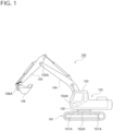
- Fig. 1 is a schematic configuration diagram of an electric construction machine
- Fig. 2 is a top-view diagram of the electric construction machine
- Fig. 3 shows a first configuration example of the driving apparatus of the electric construction machine
- Fig. 4 shows a configuration example of a charge/discharge circuit
- Fig. 5 shows a second configuration example of the driving apparatus of the electric construction machine
- Fig. 6 shows a third configuration example of the driving apparatus of the electric construction machine
- Fig. 7 schematically shows the change with time t in voltage V supplied to a DC/AC voltage bus by a charge/discharge converter
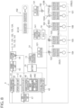
- Fig. 8 shows a configuration example of a power control device of the electric construction machine
- Fig. 1 is a schematic configuration diagram of an electric construction machine
- Fig. 2 is a top-view diagram of the electric construction machine
- Fig. 3 shows a first configuration example of the driving apparatus of the electric construction machine
- Fig. 4 shows a configuration example of a charge/discharge circuit
- Fig. 9 shows current command value of a motor in each actuator in the dq coordinate system
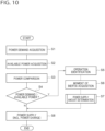
- Fig. 10 is a flowchart showing an example of a power control process by the power control device
- Fig. 11 schematically shows an example of a determination process, a power allocation amount determination process, and a power supply process
- Fig. 12 is a flowchart showing an example of the power supply amount determination process by a determination unit
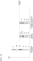
- Fig. 13 shows an example of the power allocation to each actuator in accordance with operation of a working unit.
- the technical concept of the driving apparatus described in the present embodiment can be applied to any electric machines equipped with a joint component.
- the present embodiment describes an example of a construction machine or electric construction machine equipped with a lower traveling body, an upper rotating body, a boom, an arm, and a bucket as joint components, this does not preclude the application of the technical concept of the driving apparatus according to the present embodiment to other electric machines.
- the technical concept of the driving apparatus according to the present embodiment may be applied to an industrial robot equipped with a joint unit or a joint as a joint component.
- the technical concept of the driving apparatus and/or a power control device described in the present embodiment can be applied to any construction machines equipped with a lower traveling body, an upper rotating body, a boom, an arm, and a bucket as joint components.
- the EMA that directly drives each joint component of an electric construction machine by a mechanical element driven by the rotational power of a motor is exemplified as an actuator, but the technical concept of according to the present embodiment can also be applied to the EHA that indirectly drives each joint component of an electric construction machine by a hydraulic device driven by the rotational power of a motor.
- Fig. 1 is a schematic configuration diagram of an electric construction machine 100.
- Fig. 2 is a top-view diagram of the electric construction machine 100. It should be noted that, in the below description, the directions such as forward (or front) and backward (or rear), upper and lower, left and right or the like, are the same as those of the electric construction machine 100.
- the forward proceeding direction of the electric construction machine 100 is simply called the forward direction
- the backward receding direction of the electric construction machine 100 is simply called the backward direction
- the upper side in the gravity direction is simply called the upper side
- the lower side in the gravity direction is simply called the lower side
- the right side in the width direction of the vehicle facing forward is simply called the right side
- the left side in the width direction of the vehicle facing forward is simply called the left side.
- an upper rotating body 102 is rotatably attached on a lower traveling body 101 that can travel forward and backward on the ground.
- the upper rotating body 102 includes a cab 103 on the front left side, and a boom 104 is attached in its front center, which can be raised and lowered.
- An arm 105 is attached to the front end of the boom 104, which can be bent up and down.
- a bucket 106 is attached to the front end of the arm 105, which can be bent up and down.
- a gyro sensor 110 is attached on the front left side of the cab 103.
- the gyro sensor 110 is attached in the upper rotating body 102 at the maximum distance from the rotation center C1.
- the gyro sensor 110 is a sensor capable of detecting the tilt angle, the tilt direction, the rotational position, and the rotational angular speed of the cab 103 (or the lower traveling body 101 and the upper rotating body 102). It should be noted that the tilt direction refers to the upward direction or the downward direction of tilting.
- the lower traveling body 101, the upper rotating body 102, the boom 104, the arm 105, and the bucket 106 are hereinafter collectively referred to as the joint component(s) of the electric construction machine 100.
- the electric construction machine 100 shown in Fig. 1 and Fig. 2 is a construction machine with five joint components.
- the lower traveling body 101 constitutes a traveling unit that can travel on the ground
- the upper rotating body 102 constitutes a rotating unit that can rotate with respect to the traveling unit
- the boom 104, the arm 105, and the bucket 106 constitute a working unit that are attached to the rotating unit to carry out work.
- the joint components are the portions that rotate when the lower traveling body 101, the upper rotating body 102, the boom 104, the arm 105, and the bucket 106 are driven, and are indicated by 101A, 102A, 104A, 105A, and 106A, respectively, in Fig. 1 .
- the joint component 101A of the lower traveling body 101 is front and rear wheels that form an endless track
- the joint component 102A of the upper rotating body 102 is a rotating axis attached to the lower traveling body 101
- the joint component 104A of the boom 104 is a bending axis attached to the upper rotating body 102
- the joint component 105A of the arm 105 is a bending axis attached to the front end of the boom 104
- the joint component 106A of the bucket 106 is a bending axis attached to the front end of the arm 105.
- the signs 101A, 102A, 104A, 105A, and 106A will not be used unless it is necessary to specify them, and the signs 101, 102, 104, 105, and 106 will be used instead.
- the expressions of "lower traveling body 101" and/or "joint component 101” shall refer to the joint component 101A depending on the context.
- Fig. 3 shows a first configuration example of a driving apparatus 1 of the electric construction machine 100.
- the driving apparatus 1 drives the lower traveling body 101, the upper rotating body 102, the boom 104, the arm 105, and the bucket 106, which are the joint components of the electric construction machine 100, based on DC voltage or DC power generated by a battery 10 as a DC power source.
- a battery 10 as a DC power source.
- an AC power source that generates AC power may be provided instead of the battery 10 as the DC power source that generates DC power.
- Each joint component of the electric construction machine 100 is provided with an actuator as a drive unit to drive each of them.
- a pair of traveling body actuators 21A and 21B that drive the lower traveling body 101 for traveling, a rotating body actuator 22 that drives the upper rotating body 102 for rotating, a boom actuator 24 that drives the boom 104 for raising and lowering, an arm actuator 25 that drives the arm 105 for bending, and a bucket actuator 26 that drives the bucket 106 for bending, are hereinafter collectively referred to as actuator(s) 2.
- Each actuator 2 is equipped with a converter, an inverter, and a motor.
- the pair of traveling body actuators 21A and 21B are equipped with converters 211A and 211B, inverters 221A and 221B, and motors 231A and 231B.
- the rotating body actuator 22 is equipped with a converter 212, an inverter 222, and a motor 232.
- the boom actuator 24 is equipped with a converter 214, an inverter 224, and a motor 234.
- the arm actuator 25 is equipped with a converter 215, an inverter 225, and a motor 235.
- the bucket actuator 26 is equipped with a converter 216, an inverter 226, and a motor 236.
- converter(s) 210 the converters 211A, 211B, 212, 214, 215, and 216 are collectively referred to as converter(s) 210
- inverters 221A, 221B, 222, 224, 225, and 226 are collectively referred to as inverter(s) 220
- motors 231A, 231B, 232, 234, 235, and 236 are collectively referred to as motor(s) 230.
- AC power converted from DC power by the battery 10 is input to the converter 210, except for the converter 212 of the rotating body actuator 22 provided in the upper rotating body 102 together with battery 10.
- DC power from the battery 10 is input to the converter 212 of the rotating body actuator 22, without being converted by a DC/AC converter 121 or a DC/AC converter 131 described below.
- Each converter 210 converts the input AC power or DC power into DC power that can operate each inverter 220 at a later stage.
- the inverter 220 generates 3-phase AC power to rotationally drive the motor 230 at a later stage, based on the DC power input from the converter 210.
- the motor 230 generates rotational power to drive the corresponding joint component, based on the 3-phase AC power input from the inverter 220.
- the battery 10 is connected to a DC voltage bus 31 via a charge/discharge converter 11.
- the charge/discharge converter 11 is a bidirectional DC/DC converter and is responsible for controlling the charge/discharge of the battery 10 and converting DC voltage.
- the DC voltage by discharging the battery 10 is converted by the charge/discharge converter 11 into prescribed DC voltage at the DC voltage bus 31.
- the prescribed DC voltage at the DC voltage bus 31 is converted by the charge/discharge converter 11 into DC voltage that can charge the battery 10.
- the prescribed DC voltage at the DC voltage bus 31 can be freely set, but it is preferable to set it to high voltage of approximately 200 V to 400 V, for example.
- the battery 10, the charge/discharge converter 11, the DC voltage bus 31, and the rotating body actuator 22 are provided in the upper rotating body 102, which is the main body of the electric construction machine 100 (the components above the single-dotted line in Fig. 3 are contained in the upper rotating body 102).
- Power for rotationally driving the upper rotating body 102 is supplied from the DC voltage bus 31, since the above described rotating body actuator 22 is connected to the DC voltage bus 31.
- a working unit power supply mechanism 12 which supplies power to the working unit configured by the boom 104, the arm 105, and the bucket 106, and a traveling body power supply mechanism 13, which supplies power to the lower traveling body 101 are provided, as branching off from the DC voltage bus 31.
- the working unit power supply mechanism 12 is equipped with a DC/AC converter 121, a boom transmission unit 122, an arm transmission unit 123, and a bucket transmission unit 124.
- the DC/AC converter 121 constitutes a (DC/AC) conversion unit that converts DC power generated by the battery 10 into AC power.
- the DC/AC converter 121 which is connected to the DC voltage bus 31 in the upper rotating body 102, converts the DC voltage supplied from the DC voltage bus 31 into AC voltage with a frequency of 1 kHz or higher.
- the frequency of AC power from a commercial power source is generally less than 100 Hz, but such a low frequency would increase the size of the coil that makes up the contactless transmission unit described below.
- the present embodiment adopts a frequency of 1 kHz or higher, which is higher than the commercial power source, thereby downsizing the coil to compactly form the contactless transmission unit in each joint component of the electric construction machine 100 with limited space.
- an AC/AC converter that converts the AC power (e.g., less than 100 Hz) generated by the AC power source into AC power having a higher frequency (e.g., 1 kHz or higher) is provided as a conversion unit instead of the DC/AC converter 121.
- the boom transmission unit 122, the arm transmission unit 123, and the bucket transmission unit 124 constitute contactless transmission units that contactlessly transmits the AC power converted by the DC/AC converter 121, in the boom 104, the arm 105, and the bucket 106, which are joint components of the electric construction machine 100.
- the boom transmission unit 122 contactlessly transmits power to the boom actuator 24 and the arm transmission unit 123
- the arm transmission unit 123 contactlessly transmits power to the arm actuator 25 and the bucket transmission unit 124
- the bucket transmission unit 124 contactlessly transmits power to the bucket actuator 26.
- the boom transmission unit 122, the arm transmission unit 123, and the bucket transmission unit 124 are connected in series by an AC voltage bus 32 that transmits AC power supplied from the DC/AC converter 121. As such, it is not necessary to provide the separate DC/AC converters 121 for each transmission unit, by connecting the boom transmission unit 122, the arm transmission unit 123, and the bucket transmission unit 124 in series, thereby simplifying the configuration of the driving apparatus 1.
- the boom transmission unit 122 is configured by a plurality of coils stored inside a connecting part such as a swivel that connects the boom 104 and the upper rotating body 102 while allowing relative rotation around a horizontal rotating axis (104A in Fig. 1 ).
- the boom transmission unit 122 is configured by a primary coil 1221 connected to the DC/AC converter 121 on the upper rotating body 102 side, a secondary coil 1222 connected to the AC voltage bus 32 on the arm 105 side, and a tertiary coil 1223 connected to the boom actuator 24.
- all or some of the coils of the boom transmission unit 122 and the DC/AC converter 121 at an earlier stage and/or the converter 214 (and even the inverter 224) at a later stage may be configured as an integrated transformer unit or a contactless transmission unit.
- the primary coil 1221, the secondary coil 1222, and the tertiary coil 1223 are magnetically coupled to each other.
- the AC power supplied from the DC/AC converter 121 to the primary coil 1221 is contactlessly transmitted to the arm 105 side and/or to the boom actuator 24, by the secondary coil 1222 and/or the tertiary coil 1223 magnetically coupled to the primary coil 1221.
- the boom actuator 24 as the drive unit of the boom 104 drives the boom 104 based on the AC power contactlessly transmitted by the primary coil 1221 and the tertiary coil 1223 in the boom transmission unit 122 as the contactless transmission unit.
- a magnetic material or the like may be inserted into the gap between the primary coil 1221, the secondary coil 1222, and the tertiary coil 1223 to increase power transmission efficiency.
- the regenerative power generated during deceleration of the motor 234 of the boom actuator 24 or the like is supplied to the tertiary coil 1223 via the inverter 224 and the converter 214, and is contactlessly transmitted to the upper rotating body 102 side and/or the arm 105 side, by the primary coil 1221 and/or the secondary coil 1222 magnetically coupled thereto.
- the regenerative power generated during deceleration or the like of the motor 235 of the arm actuator 25 and/or the motor 236 of the bucket actuator 26 is supplied to the secondary coil 1222 via the AC voltage bus 32, and is contactlessly transmitted to the upper rotating body 102 side and/or the boom actuator 24, by the primary coil 1221 and/or the tertiary coil 1223 magnetically coupled thereto.
- the magnetic coupling between each coil 1221, 1222, and 1223 may be such that the magnitude of the AC voltage contactlessly transmitted is kept stable, or may be realized by something like a transformer that changes the magnitude of the AC voltage contactlessly transmitted.
- the arm transmission unit 123 is configured by a plurality of coils stored inside a connecting part such as a swivel that connects the arm 105 and the boom 104 while allowing relative rotation around a horizontal rotating axis (105A in Fig. 1 ).
- the arm transmission unit 123 is configured by a primary coil 1231 connected to the AC voltage bus 32 on the boom 104 side, a secondary coil 1232 connected to the AC voltage bus 32 on the bucket 106 side, and a tertiary coil 1233 connected to the arm actuator 25.
- the primary coil 1231, the secondary coil 1232, and the tertiary coil 1233 are magnetically coupled to each other.
- the AC power supplied from the secondary coil 1222 of the boom transmission unit 122 to the primary coil 1231 via the AC voltage bus 32 is contactlessly transmitted to the bucket 106 side and/or to the arm actuator 25, by the secondary coil 1232 and/or the tertiary coil 1233 magnetically coupled to the primary coil 1231.
- the arm actuator 25 as the drive unit of the arm 105 drives the arm 105 based on the AC power contactlessly transmitted by the primary coil 1231 and the tertiary coil 1233 in the arm transmission unit 123 as the contactless transmission unit.
- a magnetic material or the like may be inserted into the gap between the primary coil 1231, the secondary coil 1232, and the tertiary coil 1233 to increase power transmission efficiency.
- the regenerative power generated during deceleration of the motor 235 of the arm actuator 25 or the like is supplied to the tertiary coil 1233 via the inverter 225 and the converter 215, and is contactlessly transmitted to the boom 104 side and/or the bucket 106 side, by the primary coil 1231 and/or the secondary coil 1232 magnetically coupled thereto.
- the regenerative power generated during deceleration or the like of the motor 236 of the bucket actuator 26 is supplied to the secondary coil 1232 via the AC voltage bus 32, and is contactlessly transmitted to the boom 104 side and/or the arm actuator 25, by the primary coil 1231 and/or the tertiary coil 1233 magnetically coupled thereto.
- the magnetic coupling between each coil 1231, 1232, and 1233 may be such that the magnitude of the AC voltage contactlessly transmitted is kept stable, or may be realized by something like a transformer that changes the magnitude of the AC voltage contactlessly transmitted.
- the bucket transmission unit 124 is configured by a plurality of coils stored inside a connecting part such as a swivel that connects the bucket 106 and the arm 105 while allowing relative rotation around a horizontal rotating axis (106A in Fig. 1 ).
- the bucket transmission unit 124 is configured by a primary coil 1241 connected to the AC voltage bus 32 on the arm 105 side, and a secondary coil 1242 connected to the bucket actuator 26.
- the primary coil 1241 and the secondary coil 1242 are magnetically coupled to each other.
- the AC power supplied from the secondary coil 1232 of the arm transmission unit 123 to the primary coil 1241 via the AC voltage bus 32 is contactlessly transmitted to the bucket actuator 26, by the secondary coil 1242 magnetically coupled to the primary coil 1241.
- the bucket actuator 26 as the drive unit of the bucket 106 drives the bucket 106 based on the AC power contactlessly transmitted by the primary coil 1241 and the secondary coil 1242 in the bucket transmission unit 124 as the contactless transmission unit.
- a magnetic material or the like may be inserted into the gap between the primary coil 1241 and the secondary coil 1242 to increase power transmission efficiency.
- the regenerative power generated during deceleration of the motor 236 of the bucket actuator 26 or the like is supplied to the secondary coil 1242 via the inverter 226 and the converter 216, and is contactlessly transmitted to the arm 105 side, by the primary coil 1241 magnetically coupled thereto.
- the magnetic coupling between each coil 1241 and 1242 may be such that the magnitude of the AC voltage contactlessly transmitted is kept stable, or may be realized by something like a transformer that changes the magnitude of the AC voltage contactlessly transmitted.
- the traveling body power supply mechanism 13 is equipped with a DC/AC converter 131, a step-down transmission unit 132, and a pair of step-up transmission units 133A and 133B.
- the DC/AC converter 131 constitutes a (DC/AC) conversion unit that converts the DC power generated by the battery 10 into AC power.
- the DC/AC converter 131 which is connected to the DC voltage bus 31 in the upper rotating body 102, converts the DC voltage supplied from the DC voltage bus 31 into AC voltage with a frequency of 1 kHz or higher.
- an AC/AC converter that converts the AC power (e.g., less than 100 Hz) generated by the AC power source into AC power having a higher frequency (e.g., 1 kHz or higher) is provided as a conversion unit instead of the DC/AC converter 131.
- the step-down transmission unit 132 and the pair of step-up transmission units 133A and 133B constitute the contactless transmission units that contactlessly transmit the AC power converted by the DC/AC converter 131 in the lower traveling body 101, which is the joint component of the electric construction machine 100, and the lower traveling body transmission unit that contactless transmission units that contactlessly transmit power to the traveling body actuators 21A and 21B, which are the drive units of the lower traveling body 101.
- the step-down transmission unit 132 is configured by a plurality of coils stored inside a connecting part such as a swivel that connects the lower traveling body 101 and the upper rotating body 102 while allowing relative rotation around a vertical rotating axis (102A in Fig. 1 ).
- the step-down transmission unit 132 is configured by a primary coil 1321 connected to the DC/AC converter 131 on the upper rotating body 102 side, and a secondary coil 1322 connected to the pair of step-up transmission units 133A and 133B in parallel on the lower traveling body 101 side.
- all or some of the coils of the step-down transmission unit 132 and the DC/AC converter 131 at an earlier stage may be configured as an integrated transformer unit or a contactless transmission unit.
- the primary coil 1321 and the secondary coil 1322 are magnetically coupled to each other.
- the AC power supplied from the DC/AC converter 131 to the primary coil 1321 is contactlessly transmitted to the lower traveling body 101 side, by the secondary coil 1322 magnetically coupled to the primary coil 1321.
- the regenerative power generated during deceleration or the like of the motor 231A and/or 231B of the traveling body actuator 21A and/or 21B is supplied to the secondary coil 1322 via the step-up transmission unit 133A and/or 133B, and is contactlessly transmitted to the upper rotating body 102 side, by the primary coil 1321 magnetically coupled thereto.
- a magnetic material or the like may be inserted into the gap between the primary coil 1321 and the secondary coil 1322 to increase power transmission efficiency.
- the step-down transmission unit 132 is configured as a transformer that changes the magnitude of the AC voltage contactlessly transmitted in accordance with the difference in the number of turns of the primary coil 1321 and the secondary coil 1322.
- the step-down transmission unit 132 decreases the AC voltage supplied from the DC/AC converter 131 on the upper rotating body 102 side and contactlessly transmits it to the lower traveling body 101.
- the DC voltage of the DC voltage bus 31 to which the DC/AC converter 131 is connected is approximately 200 V to 400 V, for example, but is converted to a lower AC voltage of approximately 40 V to 60 V by the step-down transmission unit 132.
- the step-down transmission unit 132 is provided in the rotating portion (turning portion) between the upper rotating body 102 and the lower traveling body 101.
- the voltage is reduced by the step-down transmission unit 132 for ensuring safety.
- the boom transmission unit 122 in the working unit power supply mechanism 12 is less likely to come into contact with a person, compared to the step-down transmission unit 132. As such, the boom transmission unit 122 does not need to step down the voltage as significantly as the step-down transmission unit 132. Therefore, the AC voltage of the AC voltage bus 32 in the working unit power supply mechanism 12 is higher than the AC voltage decreased by the step-down transmission unit 132.
- the pair of step-up transmission units 133A and 133B are provided in parallel corresponding to a pair of left and right lower traveling bodies 101 such as crawlers. In the following description, they are collectively referred to as step-up transmission unit(s) 133.
- the pair of traveling body actuators 21A and 21B are collectively referred to as traveling body actuator(s) 21
- the pair of converters 211A and 211B are collectively referred to as converter(s) 211
- the pair of inverters 221A and 221B are collectively referred to as inverter(s) 221
- the pair of motors 231A and 231B are collectively referred to as motor(s) 231.
- the step-up transmission unit 133 is configured by a plurality of coils stored inside each of the left and right lower traveling bodies 101. Specifically, the step-up transmission unit 133 is configured by a primary coil 1331 connected to the secondary coil 1322 of the step-down transmission unit 132, and a secondary coil 1332 connected to the traveling body actuator 21. It should be noted that all or some of the coils of the step-up transmission unit 133 and the converter 211 (and even the inverter 221) at a later stage may be configured as an integrated transformer unit or a contactless transmission unit.
- the primary coil 1331 and the secondary coil 1332 are magnetically coupled to each other.
- the AC power supplied from the secondary coil 1322 of the step-down transmission unit 132 to the primary coil 1331 is contactlessly transmitted to the traveling body actuator 21, by the secondary coil 1332 magnetically coupled to the primary coil 1331.
- the regenerative power generated during deceleration or the like of the motor 231 of the traveling body actuator 21 is supplied to the secondary coil 1332 via the inverter 221 and the converter 211, and is contactlessly transmitted to the secondary coil 1322 of the step-down transmission unit 132 and/or the primary coil 1331 of the other step-up transmission unit 133, by the primary coil 1331 magnetically coupled thereto.
- a magnetic material or the like may be inserted into the gap between the primary coil 1331 and the secondary coil 1332 to increase power transmission efficiency.
- the step-up transmission unit 133 is configured as a transformer that changes the magnitude of the AC voltage contactlessly transmitted in accordance with the difference in the number of turns of the primary coil 1331 and the secondary coil 1332.
- the step-up transmission unit 133 increases the AC voltage supplied from the secondary coil 1322 of the step-down transmission unit 132 and contactlessly transmits it to the traveling body actuator 21.
- the AC voltage that has been stepped down to approximately 40 V to 60 V by the step-down transmission unit 132 is stepped up by the step-up transmission unit 133 to a magnitude that can operate the converter 211 of the traveling body actuator 21.
- the traveling body actuator 21 as the drive unit of the lower traveling body 101 drives the lower traveling body 101 based on the AC power contactlessly transmitted by the step-down transmission unit 132 and the step-up transmission unit 133 as the contactless transmission units.
- the regenerative power collected in the actuator 2 of each joint component is used to drive the joint component by another actuator 2, and is also used to charge the capacitor 14 as the regenerative power charge unit, which is configured by an electric double-layer capacitor (EDLC) or the like connected to the DC voltage bus 31.
- EDLC electric double-layer capacitor
- the regenerative power collected in the boom actuator 24, the arm actuator 25, and the bucket actuator 26, which are interconnected by the AC voltage bus 32 is preferentially consumed by the group of these actuators, and is returned to the upper rotating body 102 side only when there is a surplus.
- the surplus that is not consumed by either the boom actuator 24 or the arm actuator 25 is converted into AC power by the converter 216 and then contactlessly transmitted to the DC/AC converter 121 of the upper rotating body 102 via the bucket transmission unit 124, the arm transmission unit 123, and the boom transmission unit 122.
- the surplus that is not consumed by either the boom actuator 24 or the bucket actuator 26 is converted into AC power by the converter 215 and then contactlessly transmitted to the DC/AC converter 121 of the upper rotating body 102 via the arm transmission unit 123 and the boom transmission unit 122.
- the surplus that is not consumed by either the arm actuator 25 or the bucket actuator 26 is converted into AC power by the converter 214 and then contactlessly transmitted to the DC/AC converter 121 of the upper rotating body 102 via the boom transmission unit 122.
- the DC/AC converter 121 that has received the excess regenerative power from at least one of the boom actuator 24, the arm actuator 25, or the bucket actuator 26 converts the AC power into DC power and supplies it to the charge/discharge circuit 141 that charges the capacitor 14.
- Fig. 4 shows a configuration example of the charge/discharge circuit 141.
- the charge/discharge circuit 141 is equipped with a high electric potential transistor 142H connected to a high electric potential line 31H of the DC voltage bus 31, a low electric potential transistor 142L connected to a low electric potential line 31L of the DC voltage bus 31, and a step-up/step-down reactor 144 connected in series with the capacitor 14, between a connection point 143 of the high electric potential transistor 142H and the low electric potential transistor 142L, and the low electric potential line 31L.
- the charge/discharge circuit 141 controls charge/discharge of the capacitor 14 and converts the DC voltage by switching operation of the high electric potential transistor 142H and the low electric potential transistor 142L.
- the regenerative power converted into DC power by the DC/AC converter 121 may be used to charge the battery 10 via the charge/discharge converter 11, or may be supplied to other actuators (i.e., the rotating body actuator 22 and/or the traveling body actuator 21) without being charged. Besides, the power charged in the capacitor 14 can be discharged by the charge/discharge circuit 141 and supplied to each actuator 2.
- the regenerative power collected in the pair of traveling body actuators 21A and 21B is preferentially consumed by the group of these actuators, and is returned to the upper rotating body 102 side only when there is a surplus.
- the surplus that is not consumed by another traveling body actuator 21 is converted into AC power by the converter 211 and then contactlessly transmitted to the DC/AC converter 131 of the upper rotating body 102 via the step-up transmission unit 133 and the step-down transmission unit 132.
- the DC/AC converter 131 that has received the excess regenerative power from at least one of the pair of traveling body actuators 21A and 21B converts the AC power into DC power and supplies it to the charge/discharge circuit 141 that charges the capacitor 14. It should be noted that the regenerative power converted into DC power by the DC/AC converter 131 may be used to charge the battery 10 via the charge/discharge converter 11, or may be supplied to other actuators (i.e., the rotating body actuator 22, the boom actuator 24, the arm actuator 25, the bucket actuator 26 or the like) without being charged.
- the regenerative power collected in the rotating body actuator 22 is converted into DC power by the converter 212 and then supplied to the charge/discharge circuit 141 that charges the capacitor 14, the charge/discharge converter 11 that charges the battery 10, or the other actuators (i.e., the traveling body actuator 21, the boom actuator 24, the arm actuator 25, the bucket actuator 26 or the like).
- each contactless transmission unit can be simply configured by the plurality of coils. Therefore, the joint component can be prevented from becoming more complicated or larger than the configuration in which wires for transmitting DC power is enclosed in the joint components, as disclosed by Patent Literature 1.
- Fig. 5 shows a second configuration example of the driving apparatus 1 of the electric construction machine 100.
- the same signs are given to the similar components to those in the first configuration example in Fig. 3 , and duplicated explanations are omitted.
- a DC/AC convertor 15 as a DC/AC conversion unit that converts the DC power generated by the battery 10 into AC power is provided in association with the battery 10.
- the DC voltage by discharging the battery 10 is converted by the DC/AC convertor 15 into AC power with a frequency of 1 kHz or higher and supplied to the AC voltage bus 33.
- the AC power in the AC voltage bus 33 is converted into DC power by the DC/AC convertor 15 to charge the battery 10.
- the AC voltage bus 33 to which the AC power is supplied from the DC/AC convertor 15 supplies the AC power with a frequency of 1 kHz or higher to the rotating body actuator 22, the working unit power supply mechanism 12, and the traveling body power supply mechanism 13.
- the DC power from the DC voltage bus 31 is input to the converter 212 of the rotating body actuator 22, but in the second configuration example in Fig. 5 , the AC power from the AC voltage bus 33 is input to the converter 212 of the rotating body actuator 22.
- the converter 212 of the rotating body actuator 22 converts the input AC power into DC power that can operate the inverter 222 at a later stage.
- the working unit power supply mechanism 12 is similar to that of the first configuration example, except that the DC/AC converter 121 in Fig. 3 is not provided.
- the function of the DC/AC converter 121 in Fig. 3 is performed by the DC/AC convertor 15 in Fig. 5 . That is, the DC/AC convertor 15 supplies AC power to the primary coil of the boom transmission unit 122 via the AC voltage bus 33.
- the traveling body power supply mechanism 13 is similar to that of the first configuration example, except that the DC/AC converter 131 in Fig. 3 is not provided.
- the function of the DC/AC converter 131 in Fig. 3 is performed by the DC/AC convertor 15 in Fig. 5 . That is, the DC/AC convertor 15 supplies AC power to the primary coil of the step-down transmission unit 132 via the AC voltage bus 33.
- an AC/DC converter 16 is provided at an earlier stage than the capacitor 14 and the charge/discharge circuit 141, which constitute the regenerative power charge unit.
- the AC/DC converter 16 converts the AC power in the AC voltage bus 33 into DC power for the charge/discharge circuit 141 to process the charging of the capacitor 14.
- the DC power output by the charge/discharge circuit 141 is converted to AC power by the AC/DC converter 16 and supplied to the AC voltage bus 33.
- Fig. 6 shows a third configuration example of the driving apparatus 1 of the electric construction machine 100.
- the charge/discharge converter 11 functions as an AC superimposition unit that superimposes AC power with a frequency of 1 kHz or higher on the DC power generated by the battery 10.
- Fig. 7 schematically shows the change with time t in voltage V supplied to the DC/AC voltage bus 34 by the charge/discharge converter 11.
- the "DC” represents the DC voltage generated by the battery 10, and the AC voltage indicated by "AC” is superimposed on it by the charge/discharge converter 11 to produce the voltage V to be supplied to the DC/AC voltage bus 34.
- the converter 212 of the rotating body actuator 22 and the charge/discharge circuit 141 which are directly connected to the DC/AC voltage bus 34, operate as in the first configuration example in Fig. 3 , based mainly on the DC component of the voltage V supplied from the DC/AC voltage bus 34.
- the working unit power supply mechanism 12 is equipped with a DC removal filter 125 as a DC removal filter and an AC/AC converter 126 as an AC conversion unit, instead of the DC/AC converter 121 in Fig. 3 .
- the DC removal filter 125 is connected to the output of the charge/discharge converter 11 as an AC superimposition unit, and removes DC power and allows AC power to pass through it, thereby functioning similarly to the DC/AC converter 121 as a DC/AC conversion unit.
- the DC component "DC” is removed by the DC removal filter 125, and the AC component "AC” passes through the DC removal filter 125.
- the AC power that has passed through the DC removal filter 125 may be supplied directly to the primary coil of the boom transmission unit 122, but in the example of Fig. 6 , the AC/AC converter 126 is provided together with an unshown resonant circuit to increase the efficiency of the contactless transmission in the boom transmission unit 122.
- the AC/AC converter 126 converts the frequency of the AC power that has passed through the DC removal filter 125 and supplies it to the boom transmission unit 122 as the contactless transmission unit. Specifically, the AC/AC converter 126 increases the frequency of the AC power and transitions the AC power to a higher frequency band where the efficiency of the contactless transmission by the boom transmission unit 122 increases.
- the AC power whose frequency is increased by the AC/AC converter 126 is supplied to the primary coil of the boom transmission unit 122. It should be noted that the AC/AC converter 126 for increasing the efficiency of the contactless transmission in the boom transmission unit 122 may be provided in the first configuration example in Fig. 3 or in the second configuration example in Fig. 5 .
- the traveling body power supply mechanism 13 is equipped with a DC removal filter 134 as a DC removal filter and an AC/AC converter 135 as an AC conversion unit, instead of the DC/AC converter 131 in Fig. 3 .
- the DC removal filter 134 is connected to the output of the charge/discharge converter 11 as an AC superimposition unit, and removes DC power and allows AC power to pass through it, thereby functioning similarly to the DC/AC converter 131 as a DC/AC conversion unit.
- the DC component "DC” is removed by the DC removal filter 134, and the AC component "AC” passes through the DC removal filter 134.
- the AC power that has passed through the DC removal filter 134 may be supplied directly to the primary coil of the step-down transmission unit 132, but in the example of Fig. 6 , the AC/AC converter 135 is provided together with an unshown resonant circuit to increase the efficiency of the contactless transmission in the step-down transmission unit 132.
- the AC/AC converter 135 converts the frequency of the AC power that has passed through the DC removal filter 134 and supplies it to the step-down transmission unit 132 as the contactless transmission unit. Specifically, the AC/AC converter 135 increases the frequency of the AC power and transitions the AC power to a higher frequency band where the efficiency of the contactless transmission by the step-down transmission unit 132 increases.
- the AC power whose frequency is increased by the AC/AC converter 135 is supplied to the primary coil of the step-down transmission unit 132.
- the AC/AC converter 135 for increasing the efficiency of the contactless transmission in the step-down transmission unit 132 may be provided in the first configuration example in Fig. 3 or in the second configuration example in Fig. 5 .
- Fig. 8 shows a configuration example of a power control device 4 of the electric construction machine 100.
- the power control device 4 is equipped with a power demand acquisition unit 41, an available power acquisition unit 42, a power comparison unit 43, a determination unit 44, an identification unit 45, and a drive information acquisition unit 47.
- the power demand acquisition unit 41 acquires the motor rotation speed N and current command values iq and id in each actuator 2, as information indicating the power demand of each actuator 2 of the lower traveling body 101, the upper rotating body 102, the boom 104, the arm 105, and the bucket 106. These information may be transmitted to the power demand acquisition unit 41 by an unshown communication device built into each actuator 2 using short-range wireless communication technology or the like, may modulate the AC power supplied to each actuator 2 as a carrier wave to be transmitted to the power demand acquisition unit 41 via the contactless transmission units 122, 123, 124, 132, and 133.
- Fig. 9 shows current command value of a motor in each actuator 2 in the dq coordinate system.
- the power demand acquisition unit 41 calculates the power demand of each actuator 2 by considering not only the q-axis current iq but also the d-axis current id. It should be noted that the power demand acquisition unit 41 may estimate the power demand of each actuator 2, based on the operation by an operator of an operation unit 40 of the electric construction machine 100, i.e., the operation command to each actuator 2.
- the available power acquisition unit 42 acquires the power that can be supplied to each actuator 2 by the power control device 4.
- the available power of the power control device 4 is the sum of the charged amount or dischargeable amount of the battery 10, the charged amount or dischargeable amount of the capacitor 14, and the regenerative power collected in each actuator 2.
- the available power acquisition unit 42 acquires the SOC (State Of Charge), which is the charge rate of the battery 10, and the dischargeable amount.
- the available power acquisition unit 42 acquires the SOC, which is the charge rate of the capacitor 14.
- the regenerative power collected in each actuator 2 is roughly classified into the working unit regenerative power collected in the actuators 24, 25, and 26 of the working unit (i.e., the boom 104, the arm 105, and the bucket 106), the traveling body regenerative power collected in the traveling body actuators 21A and 21B of the lower traveling body 101, and the rotating body regenerative power collected in actuator 22 of the upper rotating body 102.
- the working unit regenerative power is preferentially consumed in the actuators 24, 25, and 26 of the working unit
- the traveling body regenerative power is preferentially consumed in the traveling body actuators 21A and 21B of the lower traveling body 101.
- the power comparison unit 43 compares the total power demand of each actuator 2 acquired by the power demand acquisition unit 41 and the available power of the power control device 4 acquired by the available power acquisition unit 42. If the total power demand of each actuator 2 is greater than the available power of the power control device 4, the determination unit 44 determines an actuator 2 that supplies power less than the power demand, in accordance with the operation of the electric construction machine 100 identified by the identification unit 45 and/or the moment of inertia of the working unit acquired by the moment of inertia acquisition unit 46. It should be noted that the determination unit 44 may determine the power to be supplied to each actuator 2, in accordance with the operation of the electric construction machine 100 identified by the identification unit 45, regardless of the relationship between the total power demand of each actuator 2 and the available power of the power control device 4.
- the determination unit 44 determines to supply power less than the power demand to an actuator 2 of the plurality of actuators 2 that requires less power in accordance with the operation of the electric construction machine 100 identified by the identification unit 45.
- a concrete example of the power supply amount determination process by the determination unit 44 is described below.
- the available power of the power control device 4 acquired by the available power acquisition unit 42 is supplied to each actuator 2 in accordance with the allocation determined by the determination unit 44.
- the excess regenerative power collected in each actuator 2 is charged to the battery 10 and/or the capacitor 14 by the charge/discharge converter 11 and/or the charge/discharge circuit 141.
- the DC/AC converter 121 which is responsible for the bidirectional power transmission between the upper rotating body 102 and the working unit, converts the DC power from the upper rotating body 102 side, such as the battery 10 or the capacitor 14, into AC power and supplies it to the actuators 24, 25, and 26 of the working unit.
- the DC/AC converter 121 converts the excess regenerative power collected in the actuators 24, 25, and 26 of the working unit from AC to DC and supplies or charges it to the battery 10, the capacitor 14 or the like of the upper rotating body 102.
- the DC/AC converter 131 which is responsible for the bidirectional power transmission between the upper rotating body 102 and the lower traveling body 101, converts the DC power from the upper rotating body 102 side, such as the battery 10 or the capacitor 14, into AC power and supplies it to the actuators 21A and 21B of the lower traveling body 101.
- the DC/AC converter 131 converts the excess regenerative power collected in the actuators 21A and 21B of the lower traveling body 101 from AC to DC and supplies or charges it to the battery 10, the capacitor 14 or the like of the upper rotating body 102.
- the determination unit 44 determines the allocation of power (including regenerative power) among the boom transmission unit 122, the arm transmission unit 123, and the bucket transmission unit 124 connected in series. Similarly, the determination unit 44 determines the allocation of power (including regenerative power) between the two step-up transmission units 133A and 133B connected in series.
- the drive information acquisition unit 47 acquires drive information of each joint component of the electric construction machine 100, i.e., each actuator 2 of the lower traveling body 101, the upper rotating body 102, the boom 104, the arm 105, and the bucket 106.
- Examples of the drive information of each actuator 2 include: operation commands by an operator received by the operation unit 40 of the electric construction machine 100; drive commands such as voltage command values and current command values applied to a motor in each actuator 2 which are generated based on the operation commands; measured data of operating parameters such as rotation speed, current, and torque of a motor in each actuator 2; and measured data of acceleration sensors or the like provided in each joint component.
- the identification unit 45 identifies the operation or motion performed by each joint component of the electric construction machine 100 based on the drive information acquired by the drive information acquisition unit 47 and the correspondence between the operation and the drive information stored in a memory or other storage unit (not shown).
- the identification unit 45 may identify the operation of the electric construction machine 100 by referring to a table that maps the operation of the electric construction machine 100 to the drive information acquired by the drive information acquisition unit 47, or may identify the operation of the electric construction machine 100 through artificial intelligence that conducted machine learning with comprehensive teacher data equivalent to such a table.
- the moment of inertia acquisition unit 46 provided in the identification unit 45 has a weight acquisition unit 461 that acquires the weight of the object being carried by the bucket 106 and a distance acquisition unit 462 that acquires the distance of the bucket 106 from the rotating axis of the upper rotating body 102.
- the moment of inertia acquisition unit 46 acquires the moment of inertia around the rotating axis of the working unit including the carried object. It should be noted that the weight or mass of the working unit (i.e., the boom 104, the arm 105, and the bucket 106) itself necessary in calculating the moment of inertia of the working unit shall be stored in advance in the moment of inertia acquisition unit 46.
- Fig. 10 is a flowchart showing an example of the power control process by the power control device 4.
- S means step or process.
- the power demand acquisition unit 41 acquires or calculates the power demand of each actuator 2 of the lower traveling body 101, the upper rotating body 102, the boom 104, the arm 105, and the bucket 106.
- the available power acquisition unit 42 acquires the power that can be supplied to each actuator 2 by the power control device 4.
- the power comparison unit 43 compares the total power demand of each actuator 2 acquired in S1 with the available power of the power control device 4 acquired in S2.
- the drive information acquisition unit 47 acquires drive information of the actuator 2 of each joint component of the electric construction machine 100, and the identification unit 45 identifies the operation performed by the electric construction machine 100 using the lower traveling body 101, the upper rotating body 102, the boom 104, the arm 105, and the bucket 106, based on the acquired drive information.
- the moment of inertia acquisition unit 46 acquires the moment of inertia around the rotating axis of the working unit including the carried object, based on the weight of the carried object of the bucket 106 acquired by the weight acquisition unit 461 and the distance of the bucket 106 from the rotating axis acquired by the distance acquisition unit 462.
- the determination unit 44 determines the power to be supplied to each actuator 2, in accordance with the operation of the electric construction machine 100 identified in S5 and/or the moment of inertia of the working unit acquired in S6. For example, the determination unit 44 determines, in accordance with the weight of the carried object acquired in S6, that the power to be supplied to the actuator 2 that bears less weight or load will be less than the power to be supplied to the actuator 2 that bears more weight or load, among actuators 2 of the upper rotating body 102, the boom 104, the arm 105, and the bucket 106. Besides, the determination unit 44 increases the power supplied to the rotating body actuator 22 as the distance acquired in S6 becomes greater.
- each actuator 2 In S8, the available power of the power control device 4 acquired in S2 is supplied or distributed to each actuator 2 via the charge/discharge converter 11, the charge/discharge circuit 141, the DC/AC converters 121 and 131 or the like. If S4 is determined to be No, in principle, each actuator 2 will be supplied with the power in accordance with the power demand acquired in S1. If S4 is determined to be Yes, the power is supplied to each actuator 2 in accordance with the allocation determined in S7. It should be noted that if excess regenerative power exceeding the power demand of each actuator 2 is generated in S8, it is charged to the battery 10 and/or the capacitor 14, by the charge/discharge converter 11 and/or the charge/discharge circuit 141.
- Fig. 11 schematically shows an example of the determination process in S4, the power allocation amount determination process in S7, and the power supply process in S8.
- the vertical axis represents power and the horizontal axis represents time.
- the curve represents the available power of the power control device 4 at each time.
- the available power of the power control device 4 is the sum of the charged amount of the battery 10, the charged amount of the capacitor 14, and the regenerative power collected in each actuator 2, which significantly varies with time.
- the stacked bar graphs shown at times T1 and T2 represent the power demand of each actuator 2 at each of these times. It should be noted that, for simplicity of the figure and the description, only the power demand of actuators 24, 25, and 26 of the working unit is shown. Therefore, the available power shown in the figure includes only the available power for the actuators 24, 25, and 26 of the working unit and does not include the available power source for the traveling body actuators 21A and 21B and the rotating body actuator 22.
- S4 is determined to be No.
- the power is supplied to each actuator 2 in accordance with the power demand shown in the figure.
- the initial total power demand of each actuator 2 is indicated by the dotted line.
- S4 is determined to be Yes, because the total power demand of each actuator 2 is larger than the available power of the power control device 4.
- the determination unit 44 determines the power to be supplied to each actuator 2, so that the total power demand of each actuator 2 becomes less than the available power of the power control device 4.
- the power is supplied to each actuator 2 within the available power of the power control device 4 in S8.
- the power allocation to at least one of the actuators 2 is reduced based on the determination by the determination unit 44, so that appropriate power allocation can be realized within the available power.
- Fig. 12 is a flowchart showing an example of the power allocation amount determination process in S7 by the determination unit 44.
- S11 it is determined whether or not the main operation of the electric construction machine 100 identified in S5 is the traveling operation by the lower traveling body 101. If S11 is determined to be Yes, the process proceeds to S12, where the power allocation to the lower traveling body 101 responsible for the main operation is kept the same, while the power allocation to the upper rotating body 102 or the working unit that requires less power is reduced. If S11 is determined to be No, the process proceeds to S13, where it is determined whether or not the main operation of the electric construction machine 100 identified in S5 is the rotating operation by the upper rotating body 102.
- S13 is determined to be Yes
- the process proceeds to S14, where the power allocation to the upper rotating body 102 responsible for the main operation is kept the same, while the power allocation to the lower traveling body 101 or the working unit that requires less power is reduced.
- S13 is determined to be No
- the process proceeds to S15, where the power is allocated to each actuator 2 in accordance with the operation of the working unit identified in S5 (e.g., digging operation, rotating and loading operation, trench digging operation, ground leveling operation).
- Fig. 13 shows an example of the power allocation to each actuator 2 in accordance with the work done by a working unit.
- the stacked bar graph of "power demand” represents the power demand of each actuator 2
- the stacked bar graphs of "digging operation” and “90-degree rotating and loading operation” represent the power allocated to each actuator 2 in accordance with the respective operations in S15.
- the "power demand” exceeds the available power of the power control device 4, but in the "digging operation” and "90-degree rotating and loading operation", appropriate power allocation is realized for each operation within the available power of the power control device 4.
- S16 it is determined whether or not the moment of inertia around the rotating axis of the working unit acquired in S6 is greater than a predetermined value. if S16 is determined to be Yes, the process proceeds to S17, where the power allocation to the upper rotating body 102 is increased from S15. This is because a larger moment of inertia of the working unit will increase the power consumption in the upper rotating body 102 that rotates the working unit. It should be noted that the power additionally allocated to the upper rotating body 102 is secured by reducing the power allocation to the lower traveling body 101 or the working unit that requires less power.
- S18 the amount of power allocated to each actuator 2 is determined through the above processes S11 to S17. As explained in Fig. 11 and Fig. 13 , the total amount of power allocated to each actuator 2 becomes less than the available power of the power control device 4.
- S19 and subsequent processes are related to the allocation of regenerative power collected in each actuator 2.
- the working unit regenerative power collected in the actuators 24, 25, and 26 of the working unit (which can be detected in S2) is preferentially allocated to the group of the working unit actuators.
- S20 it is determined whether or not the total amount of the working unit regenerative power detected in S2 is greater than the total amount of the power allocated to the actuators 24, 25, and 26 of the working unit determined in S18. If S20 is determined to be Yes, the process proceeds to S21, where the excess working unit regenerative power is returned to the upper rotating body 102 side or the battery 10/the capacitor 14 side via the DC/AC converter 121.
- the traveling body regenerative power collected in the traveling body actuators 21A and 21B of the lower traveling body 101 (which can be detected in S2) is preferentially allocated to the group of the traveling body actuators.
- S23 it is determined whether or not the total amount of the traveling body regenerative power detected in S2 is greater than the total amount of the power allocated to the traveling body actuators 21A and 21B of the lower traveling body 101 determined in S18. If S23 is determined to be Yes, the process proceeds to S24, where the excess traveling body regenerative power is returned to the upper rotating body 102 side or the battery 10/the capacitor 14 side via the DC/AC converter 131.
- the power allocation to at least one of the actuators 2 is reduced based on the determination by the determination unit 44, so that appropriate power allocation can be realized within the available power.
- the power source is configured by the battery 10
- the continuous operating time of the power control device 4 and the electric construction machine 100 can be extended by efficiently utilizing the limited charged amount.
- the power control device 4 in Fig. 8 , the AC power supplied to each actuator 2 is contactlessly transmitted via the contactless transmission units 122, 123, 124, 132, and 133, but the power control device 4 according to the present invention is also applicable to an electric construction machine with a configuration in which the DC power generated by the battery 10 is supplied to each actuator 2 by means of wiring.
- each joint component of the electric construction machine 100 may be indirectly driven by the actuator 2.
- the actuator 2 may be configured as the EHA by using the motor 230 in controlling a hydraulic valve that controls the hydraulic pressure to each hydraulic device.
- the construction machine or the electric construction machine having the lower traveling body 101, the upper rotating body 102, the boom 104, the arm 105, and the bucket 106 as the joint components is exemplified.
- the present invention can be applied to any construction machine with other joint components.
- bulldozers, scrapers, excavators, shovels, hauling machines, dump trucks, trailers, shovel loaders, fork loaders, belt conveyors, cranes, construction lifts, forklifts, pile driving machines, drilling machines, boring machines, rock drills, road rollers, truck mixers, compressors, pumps, winches, or the like are examples of such a construction machine.
- each device described in the embodiment can be realized by hardware resources or software resources, or by cooperation of hardware resources and software resources.
- hardware resources processor, ROM, RAM, and other LSI can be utilized.
- software resources operating system, application, and other program can be utilized.
- some or all of a plurality of functions provided in a distributed manner may be provided by incorporating them into an integral function.
- an integral function incorporating a plurality of functions may be provided by distributing some or all of the plurality of functions. Regardless of whether the functions are incorporated or distributed, it is sufficient if they are configured so that the purpose of the present invention can be achieved.
- the present invention relates to power control technology in a construction machine.
- 1 driving apparatus, 2 actuator, 4 power control device 10 battery, 11 charge/discharge converter, 12 working unit power supply mechanism, 13 traveling body power supply mechanism, 14 capacitor, 15 DC/AC converter, 16 AC/DC converter, 21 traveling body actuator, 22 rotating body actuator, 24 boom actuator, 25 arm actuator, 26 bucket actuator, 31 DC voltage bus, 32 AC voltage bus, 33 AC voltage bus, 34 DC/AC voltage bus, 40 operation unit, 41 power demand acquisition unit, 42 available power acquisition unit, 43 power comparison unit, 44 determination unit, 45 identification unit, 46 moment of inertia acquisition unit, 100 electric construction machine, 101 lower traveling body, 102 upper rotating body, 104 boom, 105 arm, 106 bucket, 121 DC/AC converter, 122 boom transmission unit, 123 arm transmission unit, 124 bucket transmission unit, 125 DC removal filter, 126 AC/AC converter, 131 DC/AC converter, 132 step-down transmission unit, 133 step-up transmission unit, 134 DC removal filter, 135 AC/AC converter, 141 charge/discharge circuit, 230 motor, 461 weight acquisition
Landscapes
- Engineering & Computer Science (AREA)
- Mining & Mineral Resources (AREA)
- Civil Engineering (AREA)
- General Engineering & Computer Science (AREA)
- Structural Engineering (AREA)
- Mechanical Engineering (AREA)
- Power Engineering (AREA)
- Operation Control Of Excavators (AREA)
Abstract
Description
- The present invention relates to power control technology in a construction machine.
- An electric construction machine driven by an electric motor (hereinafter also referred to as a motor) and a hybrid construction machine in which a hydraulic device and an electric motor are used together are known as construction machines used at construction sites (hereinafter also collectively referred to electric construction machines). An actuator that directly drives each joint component of an electric construction machine by a mechanical element such as a ball screw driven by the rotational power of a motor is called an electro-mechanical actuator (EMA). And, an actuator that indirectly drives each joint component of an electric construction machine by a hydraulic device such as a hydraulic pump driven by the rotational power of a motor is called an electro-hydraulic actuator (EHA).
- [PATENT LITERATURE 1]
Japanese Patent Application Publication NO. 2008-88660 - In the electric construction machine of
Patent Literature 1, a generator is provided to generate power to drive each joint component such as a lower traveling body, an upper rotating body, a boom, an arm, and a bucket. The amount of the generated power by the generator varies, and the power required by each joint component also significantly varies depending on operation of the electric construction machine. Therefore, it is likely that the power required by each joint component is not appropriately supplied from the generator. - The present invention has been made in consideration of such a situation, and its purpose is to provide a power control device that can appropriately distribute power in a construction machine.
- In order to solve the above issue, a power control device in a construction machine equipped with a plurality of joint components and a power source that supplies power to a plurality of drive units that drive the plurality of joint components according to one embodiment of the present invention includes: a drive information acquisition unit that acquires drive information of the plurality of drive units; an identification unit that identifies the operation performed by the construction machine by the plurality of joint components based on the drive information; and a determination unit that determines power to be supplied to the plurality of drive units in accordance with the identified operation of the construction machine. According to the present embodiment, power supply amount to each drive unit is determined in accordance with the identified operation of the construction machine based on the drive information of each drive unit, thereby realizing appropriate power allocation among each drive unit.
- Another embodiment of the present invention is a power control method in a construction machine equipped with a plurality of joint components and a power source that supplies power to a plurality of drive units that drive the plurality of joint components. This method includes: a drive information acquisition step that acquires drive information of the plurality of drive units; an identification step that identifies the operation performed by the construction machine by the plurality of joint components based on the drive information; and a determination step that determines power to be supplied to the plurality of drive units in accordance with the identified operation of the construction machine.
- It should be noted that any combination of the above components, or any conversion of the expression of the present invention among methods, devices, systems, storage media, computer programs and the like, are also valid as embodiments of the present invention.
- According to the present invention, power can be appropriately distributed in a construction machine.
-
Fig. 1 is a schematic configuration diagram of an electric construction machine;Fig. 2 is a top-view diagram of the electric construction machine;Fig. 3 shows a first configuration example of the driving apparatus of the electric construction machine;Fig. 4 shows a configuration example of a charge/discharge circuit;Fig. 5 shows a second configuration example of the driving apparatus of the electric construction machine;Fig. 6 shows a third configuration example of the driving apparatus of the electric construction machine;Fig. 7 schematically shows the change with time t in voltage V supplied to a DC/AC voltage bus by a charge/discharge converter;Fig. 8 shows a configuration example of a power control device of the electric construction machine;Fig. 9 shows current command value of a motor in each actuator in the dq coordinate system;Fig. 10 is a flowchart showing an example of a power control process by the power control device;Fig. 11 schematically shows an example of a determination process, a power allocation amount determination process, and a power supply process;Fig. 12 is a flowchart showing an example of the power supply amount determination process by a determination unit; andFig. 13 shows an example of the power allocation to each actuator in accordance with operation of a working unit. - The technical concept of the driving apparatus described in the present embodiment can be applied to any electric machines equipped with a joint component. Although the present embodiment describes an example of a construction machine or electric construction machine equipped with a lower traveling body, an upper rotating body, a boom, an arm, and a bucket as joint components, this does not preclude the application of the technical concept of the driving apparatus according to the present embodiment to other electric machines. For example, the technical concept of the driving apparatus according to the present embodiment may be applied to an industrial robot equipped with a joint unit or a joint as a joint component. Besides, the technical concept of the driving apparatus and/or a power control device described in the present embodiment can be applied to any construction machines equipped with a lower traveling body, an upper rotating body, a boom, an arm, and a bucket as joint components. Besides, in the present embodiment, the EMA that directly drives each joint component of an electric construction machine by a mechanical element driven by the rotational power of a motor is exemplified as an actuator, but the technical concept of according to the present embodiment can also be applied to the EHA that indirectly drives each joint component of an electric construction machine by a hydraulic device driven by the rotational power of a motor.
-
Fig. 1 is a schematic configuration diagram of anelectric construction machine 100.Fig. 2 is a top-view diagram of theelectric construction machine 100. It should be noted that, in the below description, the directions such as forward (or front) and backward (or rear), upper and lower, left and right or the like, are the same as those of theelectric construction machine 100. That is, in the below description, the forward proceeding direction of theelectric construction machine 100 is simply called the forward direction, the backward receding direction of theelectric construction machine 100 is simply called the backward direction, the upper side in the gravity direction is simply called the upper side, the lower side in the gravity direction is simply called the lower side, the right side in the width direction of the vehicle facing forward is simply called the right side, and the left side in the width direction of the vehicle facing forward is simply called the left side. - In the
electric construction machine 100, which is a construction machine, an upper rotatingbody 102 is rotatably attached on a lower travelingbody 101 that can travel forward and backward on the ground. The upper rotatingbody 102 includes acab 103 on the front left side, and aboom 104 is attached in its front center, which can be raised and lowered. Anarm 105 is attached to the front end of theboom 104, which can be bent up and down. Abucket 106 is attached to the front end of thearm 105, which can be bent up and down. - A
gyro sensor 110 is attached on the front left side of thecab 103. In other words, thegyro sensor 110 is attached in the upper rotatingbody 102 at the maximum distance from the rotation center C1. Thegyro sensor 110 is a sensor capable of detecting the tilt angle, the tilt direction, the rotational position, and the rotational angular speed of the cab 103 (or thelower traveling body 101 and the upper rotating body 102). It should be noted that the tilt direction refers to the upward direction or the downward direction of tilting. - The lower
traveling body 101, the upper rotatingbody 102, theboom 104, thearm 105, and thebucket 106 are hereinafter collectively referred to as the joint component(s) of theelectric construction machine 100. As such, theelectric construction machine 100 shown inFig. 1 andFig. 2 is a construction machine with five joint components. It should be noted that the lower travelingbody 101 constitutes a traveling unit that can travel on the ground, the upper rotatingbody 102 constitutes a rotating unit that can rotate with respect to the traveling unit, and theboom 104, thearm 105, and thebucket 106 constitute a working unit that are attached to the rotating unit to carry out work. - Strictly speaking, the joint components are the portions that rotate when the lower
traveling body 101, the upperrotating body 102, theboom 104, thearm 105, and thebucket 106 are driven, and are indicated by 101A, 102A, 104A, 105A, and 106A, respectively, inFig. 1 . Thejoint component 101A of thelower traveling body 101 is front and rear wheels that form an endless track, thejoint component 102A of the upper rotatingbody 102 is a rotating axis attached to thelower traveling body 101, thejoint component 104A of theboom 104 is a bending axis attached to the upperrotating body 102, thejoint component 105A of thearm 105 is a bending axis attached to the front end of theboom 104, and thejoint component 106A of thebucket 106 is a bending axis attached to the front end of thearm 105. Hereinafter, thesigns signs traveling body 101" and/or "joint component 101" shall refer to thejoint component 101A depending on the context. -
Fig. 3 shows a first configuration example of adriving apparatus 1 of theelectric construction machine 100. The drivingapparatus 1 drives the lower travelingbody 101, the upper rotatingbody 102, theboom 104, thearm 105, and thebucket 106, which are the joint components of theelectric construction machine 100, based on DC voltage or DC power generated by abattery 10 as a DC power source. It should be noted that an AC power source that generates AC power may be provided instead of thebattery 10 as the DC power source that generates DC power. Each joint component of theelectric construction machine 100 is provided with an actuator as a drive unit to drive each of them. A pair oftraveling body actuators traveling body 101 for traveling, a rotatingbody actuator 22 that drives the upper rotatingbody 102 for rotating, aboom actuator 24 that drives theboom 104 for raising and lowering, anarm actuator 25 that drives thearm 105 for bending, and abucket actuator 26 that drives thebucket 106 for bending, are hereinafter collectively referred to as actuator(s) 2. - Each
actuator 2 is equipped with a converter, an inverter, and a motor. The pair oftraveling body actuators converters inverters motors body actuator 22 is equipped with aconverter 212, aninverter 222, and amotor 232. Theboom actuator 24 is equipped with aconverter 214, aninverter 224, and amotor 234. Thearm actuator 25 is equipped with aconverter 215, aninverter 225, and amotor 235. Thebucket actuator 26 is equipped with aconverter 216, aninverter 226, and amotor 236. Hereinafter, theconverters inverters motors - As described below, AC power converted from DC power by the
battery 10 is input to theconverter 210, except for theconverter 212 of therotating body actuator 22 provided in the upper rotatingbody 102 together withbattery 10. DC power from thebattery 10 is input to theconverter 212 of therotating body actuator 22, without being converted by a DC/AC converter 121 or a DC/AC converter 131 described below. Eachconverter 210 converts the input AC power or DC power into DC power that can operate eachinverter 220 at a later stage. Theinverter 220 generates 3-phase AC power to rotationally drive themotor 230 at a later stage, based on the DC power input from theconverter 210. Themotor 230 generates rotational power to drive the corresponding joint component, based on the 3-phase AC power input from theinverter 220. - The
battery 10 is connected to aDC voltage bus 31 via a charge/discharge converter 11. The charge/discharge converter 11 is a bidirectional DC/DC converter and is responsible for controlling the charge/discharge of thebattery 10 and converting DC voltage. When discharging thebattery 10, the DC voltage by discharging thebattery 10 is converted by the charge/discharge converter 11 into prescribed DC voltage at theDC voltage bus 31. When charging thebattery 10, the prescribed DC voltage at theDC voltage bus 31 is converted by the charge/discharge converter 11 into DC voltage that can charge thebattery 10. The prescribed DC voltage at theDC voltage bus 31 can be freely set, but it is preferable to set it to high voltage of approximately 200 V to 400 V, for example. - Among the above components, the
battery 10, the charge/discharge converter 11, theDC voltage bus 31, and therotating body actuator 22 are provided in the upperrotating body 102, which is the main body of the electric construction machine 100 (the components above the single-dotted line inFig. 3 are contained in the upper rotating body 102). Power for rotationally driving the upperrotating body 102 is supplied from theDC voltage bus 31, since the above described rotatingbody actuator 22 is connected to theDC voltage bus 31. Besides, a working unitpower supply mechanism 12, which supplies power to the working unit configured by theboom 104, thearm 105, and thebucket 106, and a traveling bodypower supply mechanism 13, which supplies power to thelower traveling body 101 are provided, as branching off from theDC voltage bus 31. - The working unit
power supply mechanism 12 is equipped with a DC/AC converter 121, aboom transmission unit 122, anarm transmission unit 123, and abucket transmission unit 124. The DC/AC converter 121 constitutes a (DC/AC) conversion unit that converts DC power generated by thebattery 10 into AC power. Specifically, the DC/AC converter 121, which is connected to theDC voltage bus 31 in the upperrotating body 102, converts the DC voltage supplied from theDC voltage bus 31 into AC voltage with a frequency of 1 kHz or higher. The frequency of AC power from a commercial power source is generally less than 100 Hz, but such a low frequency would increase the size of the coil that makes up the contactless transmission unit described below. Therefore, the present embodiment adopts a frequency of 1 kHz or higher, which is higher than the commercial power source, thereby downsizing the coil to compactly form the contactless transmission unit in each joint component of theelectric construction machine 100 with limited space. It should be noted that in case an AC power source that generates AC power is provided instead of thebattery 10 that generates DC power, an AC/AC converter that converts the AC power (e.g., less than 100 Hz) generated by the AC power source into AC power having a higher frequency (e.g., 1 kHz or higher) is provided as a conversion unit instead of the DC/AC converter 121. - The
boom transmission unit 122, thearm transmission unit 123, and thebucket transmission unit 124 constitute contactless transmission units that contactlessly transmits the AC power converted by the DC/AC converter 121, in theboom 104, thearm 105, and thebucket 106, which are joint components of theelectric construction machine 100. Specifically, theboom transmission unit 122 contactlessly transmits power to theboom actuator 24 and thearm transmission unit 123, thearm transmission unit 123 contactlessly transmits power to thearm actuator 25 and thebucket transmission unit 124, and thebucket transmission unit 124 contactlessly transmits power to thebucket actuator 26. Theboom transmission unit 122, thearm transmission unit 123, and thebucket transmission unit 124 are connected in series by anAC voltage bus 32 that transmits AC power supplied from the DC/AC converter 121. As such, it is not necessary to provide the separate DC/AC converters 121 for each transmission unit, by connecting theboom transmission unit 122, thearm transmission unit 123, and thebucket transmission unit 124 in series, thereby simplifying the configuration of the drivingapparatus 1. - The
boom transmission unit 122 is configured by a plurality of coils stored inside a connecting part such as a swivel that connects theboom 104 and the upperrotating body 102 while allowing relative rotation around a horizontal rotating axis (104A inFig. 1 ). Specifically, theboom transmission unit 122 is configured by aprimary coil 1221 connected to the DC/AC converter 121 on the upperrotating body 102 side, asecondary coil 1222 connected to theAC voltage bus 32 on thearm 105 side, and atertiary coil 1223 connected to theboom actuator 24. It should be noted that all or some of the coils of theboom transmission unit 122 and the DC/AC converter 121 at an earlier stage and/or the converter 214 (and even the inverter 224) at a later stage may be configured as an integrated transformer unit or a contactless transmission unit. - The
primary coil 1221, thesecondary coil 1222, and thetertiary coil 1223 are magnetically coupled to each other. The AC power supplied from the DC/AC converter 121 to theprimary coil 1221 is contactlessly transmitted to thearm 105 side and/or to theboom actuator 24, by thesecondary coil 1222 and/or thetertiary coil 1223 magnetically coupled to theprimary coil 1221. As such, theboom actuator 24 as the drive unit of theboom 104 drives theboom 104 based on the AC power contactlessly transmitted by theprimary coil 1221 and thetertiary coil 1223 in theboom transmission unit 122 as the contactless transmission unit. It should be noted that a magnetic material or the like may be inserted into the gap between theprimary coil 1221, thesecondary coil 1222, and thetertiary coil 1223 to increase power transmission efficiency. - Besides, the regenerative power generated during deceleration of the
motor 234 of theboom actuator 24 or the like is supplied to thetertiary coil 1223 via theinverter 224 and theconverter 214, and is contactlessly transmitted to the upperrotating body 102 side and/or thearm 105 side, by theprimary coil 1221 and/or thesecondary coil 1222 magnetically coupled thereto. As described below, the regenerative power generated during deceleration or the like of themotor 235 of thearm actuator 25 and/or themotor 236 of thebucket actuator 26 is supplied to thesecondary coil 1222 via theAC voltage bus 32, and is contactlessly transmitted to the upperrotating body 102 side and/or theboom actuator 24, by theprimary coil 1221 and/or thetertiary coil 1223 magnetically coupled thereto. It should be noted that the magnetic coupling between eachcoil - The
arm transmission unit 123 is configured by a plurality of coils stored inside a connecting part such as a swivel that connects thearm 105 and theboom 104 while allowing relative rotation around a horizontal rotating axis (105A inFig. 1 ). Specifically, thearm transmission unit 123 is configured by aprimary coil 1231 connected to theAC voltage bus 32 on theboom 104 side, asecondary coil 1232 connected to theAC voltage bus 32 on thebucket 106 side, and atertiary coil 1233 connected to thearm actuator 25. - The
primary coil 1231, thesecondary coil 1232, and thetertiary coil 1233 are magnetically coupled to each other. The AC power supplied from thesecondary coil 1222 of theboom transmission unit 122 to theprimary coil 1231 via theAC voltage bus 32 is contactlessly transmitted to thebucket 106 side and/or to thearm actuator 25, by thesecondary coil 1232 and/or thetertiary coil 1233 magnetically coupled to theprimary coil 1231. As such, thearm actuator 25 as the drive unit of thearm 105 drives thearm 105 based on the AC power contactlessly transmitted by theprimary coil 1231 and thetertiary coil 1233 in thearm transmission unit 123 as the contactless transmission unit. It should be noted that a magnetic material or the like may be inserted into the gap between theprimary coil 1231, thesecondary coil 1232, and thetertiary coil 1233 to increase power transmission efficiency. - Besides, the regenerative power generated during deceleration of the
motor 235 of thearm actuator 25 or the like is supplied to thetertiary coil 1233 via theinverter 225 and theconverter 215, and is contactlessly transmitted to theboom 104 side and/or thebucket 106 side, by theprimary coil 1231 and/or thesecondary coil 1232 magnetically coupled thereto. As described below, the regenerative power generated during deceleration or the like of themotor 236 of thebucket actuator 26 is supplied to thesecondary coil 1232 via theAC voltage bus 32, and is contactlessly transmitted to theboom 104 side and/or thearm actuator 25, by theprimary coil 1231 and/or thetertiary coil 1233 magnetically coupled thereto. It should be noted that the magnetic coupling between eachcoil - The
bucket transmission unit 124 is configured by a plurality of coils stored inside a connecting part such as a swivel that connects thebucket 106 and thearm 105 while allowing relative rotation around a horizontal rotating axis (106A inFig. 1 ). Specifically, thebucket transmission unit 124 is configured by aprimary coil 1241 connected to theAC voltage bus 32 on thearm 105 side, and asecondary coil 1242 connected to thebucket actuator 26. - The
primary coil 1241 and thesecondary coil 1242 are magnetically coupled to each other. The AC power supplied from thesecondary coil 1232 of thearm transmission unit 123 to theprimary coil 1241 via theAC voltage bus 32 is contactlessly transmitted to thebucket actuator 26, by thesecondary coil 1242 magnetically coupled to theprimary coil 1241. As such, thebucket actuator 26 as the drive unit of thebucket 106 drives thebucket 106 based on the AC power contactlessly transmitted by theprimary coil 1241 and thesecondary coil 1242 in thebucket transmission unit 124 as the contactless transmission unit. It should be noted that a magnetic material or the like may be inserted into the gap between theprimary coil 1241 and thesecondary coil 1242 to increase power transmission efficiency. - Besides, the regenerative power generated during deceleration of the
motor 236 of thebucket actuator 26 or the like is supplied to thesecondary coil 1242 via theinverter 226 and theconverter 216, and is contactlessly transmitted to thearm 105 side, by theprimary coil 1241 magnetically coupled thereto. It should be noted that the magnetic coupling between eachcoil - The traveling body
power supply mechanism 13 is equipped with a DC/AC converter 131, a step-downtransmission unit 132, and a pair of step-uptransmission units AC converter 131 constitutes a (DC/AC) conversion unit that converts the DC power generated by thebattery 10 into AC power. Specifically, the DC/AC converter 131, which is connected to theDC voltage bus 31 in the upperrotating body 102, converts the DC voltage supplied from theDC voltage bus 31 into AC voltage with a frequency of 1 kHz or higher. It should be noted that in case an AC power source that generates AC power is provided instead of thebattery 10 that generates DC power, an AC/AC converter that converts the AC power (e.g., less than 100 Hz) generated by the AC power source into AC power having a higher frequency (e.g., 1 kHz or higher) is provided as a conversion unit instead of the DC/AC converter 131. The step-downtransmission unit 132 and the pair of step-uptransmission units AC converter 131 in thelower traveling body 101, which is the joint component of theelectric construction machine 100, and the lower traveling body transmission unit that contactless transmission units that contactlessly transmit power to the travelingbody actuators lower traveling body 101. - The step-down
transmission unit 132 is configured by a plurality of coils stored inside a connecting part such as a swivel that connects thelower traveling body 101 and the upperrotating body 102 while allowing relative rotation around a vertical rotating axis (102A inFig. 1 ). Specifically, the step-downtransmission unit 132 is configured by aprimary coil 1321 connected to the DC/AC converter 131 on the upperrotating body 102 side, and asecondary coil 1322 connected to the pair of step-uptransmission units lower traveling body 101 side. It should be noted that all or some of the coils of the step-downtransmission unit 132 and the DC/AC converter 131 at an earlier stage may be configured as an integrated transformer unit or a contactless transmission unit. - The
primary coil 1321 and thesecondary coil 1322 are magnetically coupled to each other. The AC power supplied from the DC/AC converter 131 to theprimary coil 1321 is contactlessly transmitted to thelower traveling body 101 side, by thesecondary coil 1322 magnetically coupled to theprimary coil 1321. As described below, the regenerative power generated during deceleration or the like of themotor 231A and/or 231B of the travelingbody actuator 21A and/or 21B is supplied to thesecondary coil 1322 via the step-uptransmission unit 133A and/or 133B, and is contactlessly transmitted to the upperrotating body 102 side, by theprimary coil 1321 magnetically coupled thereto. It should be noted that a magnetic material or the like may be inserted into the gap between theprimary coil 1321 and thesecondary coil 1322 to increase power transmission efficiency. - The step-down
transmission unit 132 is configured as a transformer that changes the magnitude of the AC voltage contactlessly transmitted in accordance with the difference in the number of turns of theprimary coil 1321 and thesecondary coil 1322. The step-downtransmission unit 132 decreases the AC voltage supplied from the DC/AC converter 131 on the upperrotating body 102 side and contactlessly transmits it to thelower traveling body 101. As described above, the DC voltage of theDC voltage bus 31 to which the DC/AC converter 131 is connected is approximately 200 V to 400 V, for example, but is converted to a lower AC voltage of approximately 40 V to 60 V by the step-downtransmission unit 132. The step-downtransmission unit 132 is provided in the rotating portion (turning portion) between the upperrotating body 102 and thelower traveling body 101. Even if a leakage of electricity should occur due to the adhesion of moisture-containing soil or water, the voltage is reduced by the step-downtransmission unit 132 for ensuring safety. It should be noted that, theboom transmission unit 122 in the working unitpower supply mechanism 12 is less likely to come into contact with a person, compared to the step-downtransmission unit 132. As such, theboom transmission unit 122 does not need to step down the voltage as significantly as the step-downtransmission unit 132. Therefore, the AC voltage of theAC voltage bus 32 in the working unitpower supply mechanism 12 is higher than the AC voltage decreased by the step-downtransmission unit 132. - The pair of step-up
transmission units bodies 101 such as crawlers. In the following description, they are collectively referred to as step-up transmission unit(s) 133. Similarly, the pair of travelingbody actuators converters inverters motors - The step-up transmission unit 133 is configured by a plurality of coils stored inside each of the left and right lower traveling
bodies 101. Specifically, the step-up transmission unit 133 is configured by aprimary coil 1331 connected to thesecondary coil 1322 of the step-downtransmission unit 132, and asecondary coil 1332 connected to the traveling body actuator 21. It should be noted that all or some of the coils of the step-up transmission unit 133 and the converter 211 (and even the inverter 221) at a later stage may be configured as an integrated transformer unit or a contactless transmission unit. - The
primary coil 1331 and thesecondary coil 1332 are magnetically coupled to each other. The AC power supplied from thesecondary coil 1322 of the step-downtransmission unit 132 to theprimary coil 1331 is contactlessly transmitted to the traveling body actuator 21, by thesecondary coil 1332 magnetically coupled to theprimary coil 1331. Besides, the regenerative power generated during deceleration or the like of the motor 231 of the traveling body actuator 21 is supplied to thesecondary coil 1332 via the inverter 221 and the converter 211, and is contactlessly transmitted to thesecondary coil 1322 of the step-downtransmission unit 132 and/or theprimary coil 1331 of the other step-up transmission unit 133, by theprimary coil 1331 magnetically coupled thereto. It should be noted that a magnetic material or the like may be inserted into the gap between theprimary coil 1331 and thesecondary coil 1332 to increase power transmission efficiency. - The step-up transmission unit 133 is configured as a transformer that changes the magnitude of the AC voltage contactlessly transmitted in accordance with the difference in the number of turns of the
primary coil 1331 and thesecondary coil 1332. The step-up transmission unit 133 increases the AC voltage supplied from thesecondary coil 1322 of the step-downtransmission unit 132 and contactlessly transmits it to the traveling body actuator 21. As described above, the AC voltage that has been stepped down to approximately 40 V to 60 V by the step-downtransmission unit 132 is stepped up by the step-up transmission unit 133 to a magnitude that can operate the converter 211 of the traveling body actuator 21. As described above, the traveling body actuator 21 as the drive unit of thelower traveling body 101 drives thelower traveling body 101 based on the AC power contactlessly transmitted by the step-downtransmission unit 132 and the step-up transmission unit 133 as the contactless transmission units. - The regenerative power collected in the
actuator 2 of each joint component is used to drive the joint component by anotheractuator 2, and is also used to charge thecapacitor 14 as the regenerative power charge unit, which is configured by an electric double-layer capacitor (EDLC) or the like connected to theDC voltage bus 31. As described below with respect to the power control device according to the present embodiment, the regenerative power collected in theboom actuator 24, thearm actuator 25, and thebucket actuator 26, which are interconnected by theAC voltage bus 32, is preferentially consumed by the group of these actuators, and is returned to the upperrotating body 102 side only when there is a surplus. - Specifically, of the regenerative power collected in the
bucket actuator 26, the surplus that is not consumed by either theboom actuator 24 or thearm actuator 25 is converted into AC power by theconverter 216 and then contactlessly transmitted to the DC/AC converter 121 of the upperrotating body 102 via thebucket transmission unit 124, thearm transmission unit 123, and theboom transmission unit 122. Of the regenerative power collected in thearm actuator 25, the surplus that is not consumed by either theboom actuator 24 or thebucket actuator 26 is converted into AC power by theconverter 215 and then contactlessly transmitted to the DC/AC converter 121 of the upperrotating body 102 via thearm transmission unit 123 and theboom transmission unit 122. Of the regenerative power collected in theboom actuator 24, the surplus that is not consumed by either thearm actuator 25 or thebucket actuator 26 is converted into AC power by theconverter 214 and then contactlessly transmitted to the DC/AC converter 121 of the upperrotating body 102 via theboom transmission unit 122. - The DC/
AC converter 121 that has received the excess regenerative power from at least one of theboom actuator 24, thearm actuator 25, or thebucket actuator 26 converts the AC power into DC power and supplies it to the charge/discharge circuit 141 that charges thecapacitor 14.Fig. 4 shows a configuration example of the charge/discharge circuit 141. The charge/discharge circuit 141 is equipped with a high electricpotential transistor 142H connected to a high electricpotential line 31H of theDC voltage bus 31, a low electricpotential transistor 142L connected to a low electricpotential line 31L of theDC voltage bus 31, and a step-up/step-downreactor 144 connected in series with thecapacitor 14, between aconnection point 143 of the high electricpotential transistor 142H and the low electricpotential transistor 142L, and the low electricpotential line 31L. The charge/discharge circuit 141 controls charge/discharge of thecapacitor 14 and converts the DC voltage by switching operation of the high electricpotential transistor 142H and the low electricpotential transistor 142L. - It should be noted that the regenerative power converted into DC power by the DC/
AC converter 121 may be used to charge thebattery 10 via the charge/discharge converter 11, or may be supplied to other actuators (i.e., therotating body actuator 22 and/or the traveling body actuator 21) without being charged. Besides, the power charged in thecapacitor 14 can be discharged by the charge/discharge circuit 141 and supplied to eachactuator 2. - Similarly, the regenerative power collected in the pair of traveling
body actuators rotating body 102 side only when there is a surplus. Specifically, of the regenerative power collected in one of the traveling body actuators 21, the surplus that is not consumed by another traveling body actuator 21 is converted into AC power by the converter 211 and then contactlessly transmitted to the DC/AC converter 131 of the upperrotating body 102 via the step-up transmission unit 133 and the step-downtransmission unit 132. - The DC/
AC converter 131 that has received the excess regenerative power from at least one of the pair of travelingbody actuators discharge circuit 141 that charges thecapacitor 14. It should be noted that the regenerative power converted into DC power by the DC/AC converter 131 may be used to charge thebattery 10 via the charge/discharge converter 11, or may be supplied to other actuators (i.e., therotating body actuator 22, theboom actuator 24, thearm actuator 25, thebucket actuator 26 or the like) without being charged. Besides, the regenerative power collected in therotating body actuator 22 is converted into DC power by theconverter 212 and then supplied to the charge/discharge circuit 141 that charges thecapacitor 14, the charge/discharge converter 11 that charges thebattery 10, or the other actuators (i.e., the traveling body actuator 21, theboom actuator 24, thearm actuator 25, thebucket actuator 26 or the like). - According to the
driving apparatus 1 described above, by providing the step-downtransmission unit 132, theboom transmission unit 122, thearm transmission unit 123, and thebucket transmission unit 124 as the contactless transmission units, to thelower traveling body 101, theboom 104, thearm 105, and thebucket 106 of the joint components of theelectric construction machine 100, it is possible to contactlessly transmit the AC power without preventing the smooth operations of these joint components. In addition, each contactless transmission unit can be simply configured by the plurality of coils. Therefore, the joint component can be prevented from becoming more complicated or larger than the configuration in which wires for transmitting DC power is enclosed in the joint components, as disclosed byPatent Literature 1. -
Fig. 5 shows a second configuration example of the drivingapparatus 1 of theelectric construction machine 100. The same signs are given to the similar components to those in the first configuration example inFig. 3 , and duplicated explanations are omitted. In the second configuration example, a DC/AC convertor 15 as a DC/AC conversion unit that converts the DC power generated by thebattery 10 into AC power is provided in association with thebattery 10. - When discharging the
battery 10, the DC voltage by discharging thebattery 10 is converted by the DC/AC convertor 15 into AC power with a frequency of 1 kHz or higher and supplied to theAC voltage bus 33. When charging thebattery 10, the AC power in theAC voltage bus 33 is converted into DC power by the DC/AC convertor 15 to charge thebattery 10. TheAC voltage bus 33 to which the AC power is supplied from the DC/AC convertor 15 supplies the AC power with a frequency of 1 kHz or higher to therotating body actuator 22, the working unitpower supply mechanism 12, and the traveling bodypower supply mechanism 13. - In the first configuration example in
Fig. 3 , the DC power from theDC voltage bus 31 is input to theconverter 212 of therotating body actuator 22, but in the second configuration example inFig. 5 , the AC power from theAC voltage bus 33 is input to theconverter 212 of therotating body actuator 22. Theconverter 212 of therotating body actuator 22 converts the input AC power into DC power that can operate theinverter 222 at a later stage. - The working unit
power supply mechanism 12 is similar to that of the first configuration example, except that the DC/AC converter 121 inFig. 3 is not provided. The function of the DC/AC converter 121 inFig. 3 is performed by the DC/AC convertor 15 inFig. 5 . That is, the DC/AC convertor 15 supplies AC power to the primary coil of theboom transmission unit 122 via theAC voltage bus 33. - The traveling body
power supply mechanism 13 is similar to that of the first configuration example, except that the DC/AC converter 131 inFig. 3 is not provided. The function of the DC/AC converter 131 inFig. 3 is performed by the DC/AC convertor 15 inFig. 5 . That is, the DC/AC convertor 15 supplies AC power to the primary coil of the step-downtransmission unit 132 via theAC voltage bus 33. - In the second configuration example shown in
Fig. 5 , an AC/DC converter 16 is provided at an earlier stage than thecapacitor 14 and the charge/discharge circuit 141, which constitute the regenerative power charge unit. the AC/DC converter 16 converts the AC power in theAC voltage bus 33 into DC power for the charge/discharge circuit 141 to process the charging of thecapacitor 14. Besides, during the discharge process of thecapacitor 14, the DC power output by the charge/discharge circuit 141 is converted to AC power by the AC/DC converter 16 and supplied to theAC voltage bus 33. -
Fig. 6 shows a third configuration example of the drivingapparatus 1 of theelectric construction machine 100. The same signs are given to the similar components to those in the first configuration example inFig. 3 , and duplicated explanations are omitted. In the third configuration example, the charge/discharge converter 11 functions as an AC superimposition unit that superimposes AC power with a frequency of 1 kHz or higher on the DC power generated by thebattery 10.Fig. 7 schematically shows the change with time t in voltage V supplied to the DC/AC voltage bus 34 by the charge/discharge converter 11. The "DC" represents the DC voltage generated by thebattery 10, and the AC voltage indicated by "AC" is superimposed on it by the charge/discharge converter 11 to produce the voltage V to be supplied to the DC/AC voltage bus 34. - The
converter 212 of therotating body actuator 22 and the charge/discharge circuit 141, which are directly connected to the DC/AC voltage bus 34, operate as in the first configuration example inFig. 3 , based mainly on the DC component of the voltage V supplied from the DC/AC voltage bus 34. - The working unit
power supply mechanism 12 is equipped with aDC removal filter 125 as a DC removal filter and an AC/AC converter 126 as an AC conversion unit, instead of the DC/AC converter 121 inFig. 3 . TheDC removal filter 125 is connected to the output of the charge/discharge converter 11 as an AC superimposition unit, and removes DC power and allows AC power to pass through it, thereby functioning similarly to the DC/AC converter 121 as a DC/AC conversion unit. In the example ofFig. 7 , the DC component "DC" is removed by theDC removal filter 125, and the AC component "AC" passes through theDC removal filter 125. - The AC power that has passed through the
DC removal filter 125 may be supplied directly to the primary coil of theboom transmission unit 122, but in the example ofFig. 6 , the AC/AC converter 126 is provided together with an unshown resonant circuit to increase the efficiency of the contactless transmission in theboom transmission unit 122. The AC/AC converter 126 converts the frequency of the AC power that has passed through theDC removal filter 125 and supplies it to theboom transmission unit 122 as the contactless transmission unit. Specifically, the AC/AC converter 126 increases the frequency of the AC power and transitions the AC power to a higher frequency band where the efficiency of the contactless transmission by theboom transmission unit 122 increases. The AC power whose frequency is increased by the AC/AC converter 126 is supplied to the primary coil of theboom transmission unit 122. It should be noted that the AC/AC converter 126 for increasing the efficiency of the contactless transmission in theboom transmission unit 122 may be provided in the first configuration example inFig. 3 or in the second configuration example inFig. 5 . - The traveling body
power supply mechanism 13 is equipped with aDC removal filter 134 as a DC removal filter and an AC/AC converter 135 as an AC conversion unit, instead of the DC/AC converter 131 inFig. 3 . TheDC removal filter 134 is connected to the output of the charge/discharge converter 11 as an AC superimposition unit, and removes DC power and allows AC power to pass through it, thereby functioning similarly to the DC/AC converter 131 as a DC/AC conversion unit. In the example ofFig. 7 , the DC component "DC" is removed by theDC removal filter 134, and the AC component "AC" passes through theDC removal filter 134. - The AC power that has passed through the
DC removal filter 134 may be supplied directly to the primary coil of the step-downtransmission unit 132, but in the example ofFig. 6 , the AC/AC converter 135 is provided together with an unshown resonant circuit to increase the efficiency of the contactless transmission in the step-downtransmission unit 132. The AC/AC converter 135 converts the frequency of the AC power that has passed through theDC removal filter 134 and supplies it to the step-downtransmission unit 132 as the contactless transmission unit. Specifically, the AC/AC converter 135 increases the frequency of the AC power and transitions the AC power to a higher frequency band where the efficiency of the contactless transmission by the step-downtransmission unit 132 increases. The AC power whose frequency is increased by the AC/AC converter 135 is supplied to the primary coil of the step-downtransmission unit 132. It should be noted that the AC/AC converter 135 for increasing the efficiency of the contactless transmission in the step-downtransmission unit 132 may be provided in the first configuration example inFig. 3 or in the second configuration example inFig. 5 . -
Fig. 8 shows a configuration example of apower control device 4 of theelectric construction machine 100. Thepower control device 4 is equipped with a powerdemand acquisition unit 41, an availablepower acquisition unit 42, apower comparison unit 43, adetermination unit 44, anidentification unit 45, and a driveinformation acquisition unit 47. - The power
demand acquisition unit 41 acquires the motor rotation speed N and current command values iq and id in eachactuator 2, as information indicating the power demand of eachactuator 2 of thelower traveling body 101, the upperrotating body 102, theboom 104, thearm 105, and thebucket 106. These information may be transmitted to the powerdemand acquisition unit 41 by an unshown communication device built into eachactuator 2 using short-range wireless communication technology or the like, may modulate the AC power supplied to eachactuator 2 as a carrier wave to be transmitted to the powerdemand acquisition unit 41 via thecontactless transmission units Fig. 9 shows current command value of a motor in eachactuator 2 in the dq coordinate system. In the dq coordinate system, the d-axis current id does not contribute to torque generation in the motor, and when id = 0, the power demand of eachactuator 2 is calculated to be iq*N, which is the q-axis current iq multiplied by the rotation speed N. On the other hand, when weak field control is used to reduce the back electromotive force due to the field magnet at high motor rotation speed, a negative d-axis current id must also flow, therefore the powerdemand acquisition unit 41 calculates the power demand of eachactuator 2 by considering not only the q-axis current iq but also the d-axis current id. It should be noted that the powerdemand acquisition unit 41 may estimate the power demand of eachactuator 2, based on the operation by an operator of anoperation unit 40 of theelectric construction machine 100, i.e., the operation command to eachactuator 2. - The available
power acquisition unit 42 acquires the power that can be supplied to eachactuator 2 by thepower control device 4. The available power of thepower control device 4 is the sum of the charged amount or dischargeable amount of thebattery 10, the charged amount or dischargeable amount of thecapacitor 14, and the regenerative power collected in eachactuator 2. As information indicating the charged amount or dischargeable amount of thebattery 10, the availablepower acquisition unit 42 acquires the SOC (State Of Charge), which is the charge rate of thebattery 10, and the dischargeable amount. As information indicating the charged amount or dischargeable amount of thecapacitor 14, the availablepower acquisition unit 42 acquires the SOC, which is the charge rate of thecapacitor 14. The regenerative power collected in eachactuator 2 is roughly classified into the working unit regenerative power collected in theactuators boom 104, thearm 105, and the bucket 106), the traveling body regenerative power collected in the travelingbody actuators lower traveling body 101, and the rotating body regenerative power collected inactuator 22 of the upperrotating body 102. As described below, the working unit regenerative power is preferentially consumed in theactuators body actuators lower traveling body 101. - The
power comparison unit 43 compares the total power demand of eachactuator 2 acquired by the powerdemand acquisition unit 41 and the available power of thepower control device 4 acquired by the availablepower acquisition unit 42. If the total power demand of eachactuator 2 is greater than the available power of thepower control device 4, thedetermination unit 44 determines anactuator 2 that supplies power less than the power demand, in accordance with the operation of theelectric construction machine 100 identified by theidentification unit 45 and/or the moment of inertia of the working unit acquired by the moment ofinertia acquisition unit 46. It should be noted that thedetermination unit 44 may determine the power to be supplied to eachactuator 2, in accordance with the operation of theelectric construction machine 100 identified by theidentification unit 45, regardless of the relationship between the total power demand of eachactuator 2 and the available power of thepower control device 4. Besides, if the total power demand of eachactuator 2 is greater than the available power of thepower control device 4, thedetermination unit 44 determines to supply power less than the power demand to anactuator 2 of the plurality ofactuators 2 that requires less power in accordance with the operation of theelectric construction machine 100 identified by theidentification unit 45. A concrete example of the power supply amount determination process by thedetermination unit 44 is described below. - The available power of the
power control device 4 acquired by the availablepower acquisition unit 42 is supplied to eachactuator 2 in accordance with the allocation determined by thedetermination unit 44. Here, the excess regenerative power collected in eachactuator 2 is charged to thebattery 10 and/or thecapacitor 14 by the charge/discharge converter 11 and/or the charge/discharge circuit 141. Besides, the DC/AC converter 121, which is responsible for the bidirectional power transmission between the upperrotating body 102 and the working unit, converts the DC power from the upperrotating body 102 side, such as thebattery 10 or thecapacitor 14, into AC power and supplies it to theactuators AC converter 121 converts the excess regenerative power collected in theactuators battery 10, thecapacitor 14 or the like of the upperrotating body 102. Similarly, the DC/AC converter 131, which is responsible for the bidirectional power transmission between the upperrotating body 102 and thelower traveling body 101, converts the DC power from the upperrotating body 102 side, such as thebattery 10 or thecapacitor 14, into AC power and supplies it to theactuators lower traveling body 101. At the same time, the DC/AC converter 131 converts the excess regenerative power collected in theactuators lower traveling body 101 from AC to DC and supplies or charges it to thebattery 10, thecapacitor 14 or the like of the upperrotating body 102. Besides, thedetermination unit 44 determines the allocation of power (including regenerative power) among theboom transmission unit 122, thearm transmission unit 123, and thebucket transmission unit 124 connected in series. Similarly, thedetermination unit 44 determines the allocation of power (including regenerative power) between the two step-uptransmission units - The drive
information acquisition unit 47 acquires drive information of each joint component of theelectric construction machine 100, i.e., eachactuator 2 of thelower traveling body 101, the upperrotating body 102, theboom 104, thearm 105, and thebucket 106. Examples of the drive information of eachactuator 2 include: operation commands by an operator received by theoperation unit 40 of theelectric construction machine 100; drive commands such as voltage command values and current command values applied to a motor in eachactuator 2 which are generated based on the operation commands; measured data of operating parameters such as rotation speed, current, and torque of a motor in eachactuator 2; and measured data of acceleration sensors or the like provided in each joint component. Theidentification unit 45 identifies the operation or motion performed by each joint component of theelectric construction machine 100 based on the drive information acquired by the driveinformation acquisition unit 47 and the correspondence between the operation and the drive information stored in a memory or other storage unit (not shown). Theidentification unit 45 may identify the operation of theelectric construction machine 100 by referring to a table that maps the operation of theelectric construction machine 100 to the drive information acquired by the driveinformation acquisition unit 47, or may identify the operation of theelectric construction machine 100 through artificial intelligence that conducted machine learning with comprehensive teacher data equivalent to such a table. The moment ofinertia acquisition unit 46 provided in theidentification unit 45 has aweight acquisition unit 461 that acquires the weight of the object being carried by thebucket 106 and adistance acquisition unit 462 that acquires the distance of thebucket 106 from the rotating axis of the upperrotating body 102. The moment ofinertia acquisition unit 46 acquires the moment of inertia around the rotating axis of the working unit including the carried object. It should be noted that the weight or mass of the working unit (i.e., theboom 104, thearm 105, and the bucket 106) itself necessary in calculating the moment of inertia of the working unit shall be stored in advance in the moment ofinertia acquisition unit 46. -
Fig. 10 is a flowchart showing an example of the power control process by thepower control device 4. In the description of the flowchart, "S" means step or process. In S1, the powerdemand acquisition unit 41 acquires or calculates the power demand of eachactuator 2 of thelower traveling body 101, the upperrotating body 102, theboom 104, thearm 105, and thebucket 106. In S2, the availablepower acquisition unit 42 acquires the power that can be supplied to eachactuator 2 by thepower control device 4. In S3, thepower comparison unit 43 compares the total power demand of eachactuator 2 acquired in S1 with the available power of thepower control device 4 acquired in S2. As the result of the power comparison in S3, if the total power demand of eachactuator 2 is greater than the available power of the power control device 4 (Yes in S4), the process proceeds to S5, and if the total power demand of eachactuator 2 is less than the available power of the power control device 4 (No in S4), the process proceeds to S8. - In S5, the drive
information acquisition unit 47 acquires drive information of theactuator 2 of each joint component of theelectric construction machine 100, and theidentification unit 45 identifies the operation performed by theelectric construction machine 100 using thelower traveling body 101, the upperrotating body 102, theboom 104, thearm 105, and thebucket 106, based on the acquired drive information. In S6, the moment ofinertia acquisition unit 46 acquires the moment of inertia around the rotating axis of the working unit including the carried object, based on the weight of the carried object of thebucket 106 acquired by theweight acquisition unit 461 and the distance of thebucket 106 from the rotating axis acquired by thedistance acquisition unit 462. In S7, thedetermination unit 44 determines the power to be supplied to eachactuator 2, in accordance with the operation of theelectric construction machine 100 identified in S5 and/or the moment of inertia of the working unit acquired in S6. For example, thedetermination unit 44 determines, in accordance with the weight of the carried object acquired in S6, that the power to be supplied to theactuator 2 that bears less weight or load will be less than the power to be supplied to theactuator 2 that bears more weight or load, amongactuators 2 of the upperrotating body 102, theboom 104, thearm 105, and thebucket 106. Besides, thedetermination unit 44 increases the power supplied to therotating body actuator 22 as the distance acquired in S6 becomes greater. - In S8, the available power of the
power control device 4 acquired in S2 is supplied or distributed to eachactuator 2 via the charge/discharge converter 11, the charge/discharge circuit 141, the DC/AC converters actuator 2 will be supplied with the power in accordance with the power demand acquired in S1. If S4 is determined to be Yes, the power is supplied to eachactuator 2 in accordance with the allocation determined in S7. It should be noted that if excess regenerative power exceeding the power demand of eachactuator 2 is generated in S8, it is charged to thebattery 10 and/or thecapacitor 14, by the charge/discharge converter 11 and/or the charge/discharge circuit 141. -
Fig. 11 schematically shows an example of the determination process in S4, the power allocation amount determination process in S7, and the power supply process in S8. The vertical axis represents power and the horizontal axis represents time. The curve represents the available power of thepower control device 4 at each time. As described above, the available power of thepower control device 4 is the sum of the charged amount of thebattery 10, the charged amount of thecapacitor 14, and the regenerative power collected in eachactuator 2, which significantly varies with time. The stacked bar graphs shown at times T1 and T2 represent the power demand of eachactuator 2 at each of these times. It should be noted that, for simplicity of the figure and the description, only the power demand ofactuators actuators body actuators rotating body actuator 22. - At time T1, since the total power demand of each
actuator 2 is less than the available power of thepower control device 4, S4 is determined to be No. In the following S8, the power is supplied to eachactuator 2 in accordance with the power demand shown in the figure. At time T2, the initial total power demand of eachactuator 2 is indicated by the dotted line. In this case, S4 is determined to be Yes, because the total power demand of eachactuator 2 is larger than the available power of thepower control device 4. In S7, thedetermination unit 44 determines the power to be supplied to eachactuator 2, so that the total power demand of eachactuator 2 becomes less than the available power of thepower control device 4. As a result, the power is supplied to eachactuator 2 within the available power of thepower control device 4 in S8. As such, if the total power demand of eachactuator 2 is greater than the available power of thepower control device 4, the power allocation to at least one of theactuators 2 is reduced based on the determination by thedetermination unit 44, so that appropriate power allocation can be realized within the available power. -
Fig. 12 is a flowchart showing an example of the power allocation amount determination process in S7 by thedetermination unit 44. In S11, it is determined whether or not the main operation of theelectric construction machine 100 identified in S5 is the traveling operation by thelower traveling body 101. If S11 is determined to be Yes, the process proceeds to S12, where the power allocation to thelower traveling body 101 responsible for the main operation is kept the same, while the power allocation to the upperrotating body 102 or the working unit that requires less power is reduced. If S11 is determined to be No, the process proceeds to S13, where it is determined whether or not the main operation of theelectric construction machine 100 identified in S5 is the rotating operation by the upperrotating body 102. If S13 is determined to be Yes, the process proceeds to S14, where the power allocation to the upperrotating body 102 responsible for the main operation is kept the same, while the power allocation to thelower traveling body 101 or the working unit that requires less power is reduced. If S13 is determined to be No, the process proceeds to S15, where the power is allocated to eachactuator 2 in accordance with the operation of the working unit identified in S5 (e.g., digging operation, rotating and loading operation, trench digging operation, ground leveling operation). -
Fig. 13 shows an example of the power allocation to eachactuator 2 in accordance with the work done by a working unit. The stacked bar graph of "power demand" represents the power demand of eachactuator 2, and the stacked bar graphs of "digging operation" and "90-degree rotating and loading operation" represent the power allocated to eachactuator 2 in accordance with the respective operations in S15. As shown in the figure, the "power demand" exceeds the available power of thepower control device 4, but in the "digging operation" and "90-degree rotating and loading operation", appropriate power allocation is realized for each operation within the available power of thepower control device 4. In the "digging operation", more power is allocated to theactuators body actuators rotating body actuator 22, which require less power, is suppressed or reduced. In the "90-degree rotating and loading operation", not only the working unit but also the upperrotating body 102 require a large amount of power, therefore the power is allocated to therotating body actuator 22 in accordance with the power demand. On the other hand, since thelower traveling body 101 is stopped in the "90-degree rotating and loading operation", the allocation or supply of power to the travelingbody actuators - In S16, it is determined whether or not the moment of inertia around the rotating axis of the working unit acquired in S6 is greater than a predetermined value. if S16 is determined to be Yes, the process proceeds to S17, where the power allocation to the upper
rotating body 102 is increased from S15. This is because a larger moment of inertia of the working unit will increase the power consumption in the upperrotating body 102 that rotates the working unit. It should be noted that the power additionally allocated to the upperrotating body 102 is secured by reducing the power allocation to thelower traveling body 101 or the working unit that requires less power. In S18, the amount of power allocated to eachactuator 2 is determined through the above processes S11 to S17. As explained inFig. 11 andFig. 13 , the total amount of power allocated to eachactuator 2 becomes less than the available power of thepower control device 4. - S19 and subsequent processes are related to the allocation of regenerative power collected in each
actuator 2. In S19, the working unit regenerative power collected in theactuators actuators rotating body 102 side or thebattery 10/thecapacitor 14 side via the DC/AC converter 121. - In S22, the traveling body regenerative power collected in the traveling
body actuators body actuators lower traveling body 101 determined in S18. If S23 is determined to be Yes, the process proceeds to S24, where the excess traveling body regenerative power is returned to the upperrotating body 102 side or thebattery 10/thecapacitor 14 side via the DC/AC converter 131. - According to the above embodiment, if the total power demand of the plurality of
actuators 2 is greater than the available power of the power source, the power allocation to at least one of theactuators 2 is reduced based on the determination by thedetermination unit 44, so that appropriate power allocation can be realized within the available power. In particular, if the power source is configured by thebattery 10, the continuous operating time of thepower control device 4 and theelectric construction machine 100 can be extended by efficiently utilizing the limited charged amount. - The present invention has been described above based on embodiments. It will be understood by those skilled in the art that the embodiments are examples, that various variations are possible in the combination of the respective components and/or the respective processing steps, and that such variations are also within the scope of the present invention.
- In the configuration example of the
power control device 4 inFig. 8 , the AC power supplied to eachactuator 2 is contactlessly transmitted via thecontactless transmission units power control device 4 according to the present invention is also applicable to an electric construction machine with a configuration in which the DC power generated by thebattery 10 is supplied to eachactuator 2 by means of wiring. - Although the embodiment describes the example of the EMA in which the
actuator 2 directly drives each joint component of theelectric construction machine 100, each joint component of theelectric construction machine 100 may be indirectly driven by theactuator 2. For example, in case each joint component is directly driven by a hydraulic motor, a hydraulic cylinder, or another hydraulic device, theactuator 2 may be configured as the EHA by using themotor 230 in controlling a hydraulic valve that controls the hydraulic pressure to each hydraulic device. - Besides, in the embodiment, the construction machine or the electric construction machine having the
lower traveling body 101, the upperrotating body 102, theboom 104, thearm 105, and thebucket 106 as the joint components is exemplified. However, the present invention can be applied to any construction machine with other joint components. For example, bulldozers, scrapers, excavators, shovels, hauling machines, dump trucks, trailers, shovel loaders, fork loaders, belt conveyors, cranes, construction lifts, forklifts, pile driving machines, drilling machines, boring machines, rock drills, road rollers, truck mixers, compressors, pumps, winches, or the like are examples of such a construction machine. - It should be noted that the functional configuration of each device described in the embodiment can be realized by hardware resources or software resources, or by cooperation of hardware resources and software resources. As hardware resources, processor, ROM, RAM, and other LSI can be utilized. As software resources, operating system, application, and other program can be utilized.
- In the embodiments disclosed in the present specification, some or all of a plurality of functions provided in a distributed manner may be provided by incorporating them into an integral function. Conversely, an integral function incorporating a plurality of functions may be provided by distributing some or all of the plurality of functions. Regardless of whether the functions are incorporated or distributed, it is sufficient if they are configured so that the purpose of the present invention can be achieved.
- The present invention relates to power control technology in a construction machine.
- 1 driving apparatus, 2 actuator, 4 power control device, 10 battery, 11 charge/discharge converter, 12 working unit power supply mechanism, 13 traveling body power supply mechanism, 14 capacitor, 15 DC/AC converter, 16 AC/DC converter, 21 traveling body actuator, 22 rotating body actuator, 24 boom actuator, 25 arm actuator, 26 bucket actuator, 31 DC voltage bus, 32 AC voltage bus, 33 AC voltage bus, 34 DC/AC voltage bus, 40 operation unit, 41 power demand acquisition unit, 42 available power acquisition unit, 43 power comparison unit, 44 determination unit, 45 identification unit, 46 moment of inertia acquisition unit, 100 electric construction machine, 101 lower traveling body, 102 upper rotating body, 104 boom, 105 arm, 106 bucket, 121 DC/AC converter, 122 boom transmission unit, 123 arm transmission unit, 124 bucket transmission unit, 125 DC removal filter, 126 AC/AC converter, 131 DC/AC converter, 132 step-down transmission unit, 133 step-up transmission unit, 134 DC removal filter, 135 AC/AC converter, 141 charge/discharge circuit, 230 motor, 461 weight acquisition unit, 462 distance acquisition unit.
Claims (13)
- A power control device in a construction machine equipped with a plurality of joint components and a power source that supplies power to a plurality of drive units that drive the plurality of joint components, comprising:a drive information acquisition unit that acquires drive information of the plurality of drive units;an identification unit that identifies the operation performed by the construction machine by the plurality of joint components based on the drive information; anda determination unit that determines power to be supplied to the plurality of drive units in accordance with the identified operation of the construction machine.
- The power control device according to claim 1, whereinthe drive information is at least one of an operation command received by an operation unit of the construction machine and a drive command for each of the plurality of drive units, and whereinthe identification unit identifies the operation performed by the construction machine based on the correspondence between the operation and the drive information stored in a storage unit and the acquired drive information.
- The power control device according to claim 1 or 2, wherein the joint component is at least one of a lower traveling body that can travel on the ground, an upper rotating body that is rotatably attached to the lower traveling body, a boom capable of being raised and lowered that is attached to the upper rotating body, an arm that is bendably attached to the boom, and a bucket that is bendably attached to the arm.
- The power control device according to claim 3, whereinthe operation of the construction machine is a traveling operation, and whereinthe determination unit determines that more power is supplied to the drive unit that drives the lower traveling body than power supplied to the drive units that drive the upper rotating body, the boom, the arm, and the bucket.
- The power control device according to claim 3, whereinthe operation of the construction machine is a rotating operation, and whereinthe determination unit determines that more power is supplied to the drive unit that drives the upper rotating body than power supplied to the drive units that drive the lower traveling body, the boom, the arm, and the bucket.
- The power control device according to claim 3, whereinthe operation of the construction machine is at least one of a digging operation, a rotating and loading operation, a trench digging operation, and a ground leveling operation using the boom, the arm, and the bucket, and whereinthe determination unit determines that more power is supplied to the drive units that drive the boom, the arm, and the bucket than power supplied to the drive unit that drives the lower traveling body.
- The power control device according to claim 6, further comprising a weight acquisition unit that acquires information indicating a weight of an object carried by the bucket, wherein
the determination unit determines that more power is supplied to the drive unit that bears more load in accordance with the weight of the carried object acquired by the weight acquisition unit, than power supplied to the drive unit that bears less load, among the each drive unit of the upper rotating body, the boom, the arm, and the bucket. - The power control device according to claim 3, further comprising a distance acquisition unit that acquires a distance of the bucket from the rotating axis of the upper rotating body, wherein
the determination unit determines that the larger the distance acquired by the distance acquisition unit, the larger the power supplied to the drive unit of the upper rotating body. - The power control device according to claim 3, wherein the determination unit determines that the regenerative power collected in the respective drive units of the boom, the arm, and the bucket is allocated among the respective drive units, and excess regenerative power exceeding the sum of the power demand of each drive unit is returned to the power source side.
- The power control device according to claim 1 or 2, whereineach of the drive units includes a motor that generates rotational power, and whereinthe drive information includes at least one of a rotation speed of each of the motors and a current command value of the motor.
- The power control device according to claim 1 or 2, further comprising:a power demand acquisition unit that acquires power demand of each of the plurality of drive units; andan available power acquisition unit that acquires at least one of a charge rate and a dischargeable amount of a battery as available power, whereinthe determination unit determines the power to be supplied to the plurality of drive units in accordance with the identified operation of the construction machine when the total of the power demand exceeds the available power.
- A power control method in a construction machine equipped with a plurality of joint components and a power source that supplies power to a plurality of drive units that drive the plurality of joint components, comprising:a drive information acquisition step that acquires drive information of the plurality of drive units;an identification step that identifies the operation performed by the construction machine by the plurality of joint components based on the drive information; anda determination step that determines power to be supplied to the plurality of drive units in accordance with the identified operation of the construction machine.
- A power control program in a construction machine equipped with a plurality of joint components and a power source that supplies power to a plurality of drive units that drive the plurality of joint components, causing a computer to perform:a drive information acquisition step that acquires drive information of the plurality of drive units;an identification step that identifies the operation performed by the construction machine by the plurality of joint components based on the drive information; anda determination step that determines power to be supplied to the plurality of drive units in accordance with the identified operation of the construction machine.
Applications Claiming Priority (3)
| Application Number | Priority Date | Filing Date | Title |
|---|---|---|---|
| JP2021175811 | 2021-10-27 | ||
| JP2022003479 | 2022-01-13 | ||
| PCT/JP2022/036269 WO2023074241A1 (en) | 2021-10-27 | 2022-09-28 | Power control device, power control method, and program for power control device |
Publications (2)
| Publication Number | Publication Date |
|---|---|
| EP4424926A1 true EP4424926A1 (en) | 2024-09-04 |
| EP4424926A4 EP4424926A4 (en) | 2025-09-10 |
Family
ID=86159811
Family Applications (1)
| Application Number | Title | Priority Date | Filing Date |
|---|---|---|---|
| EP22886573.9A Pending EP4424926A4 (en) | 2021-10-27 | 2022-09-28 | POWER CONTROL DEVICE, POWER CONTROL METHOD AND PROGRAM FOR A POWER CONTROL DEVICE |
Country Status (4)
| Country | Link |
|---|---|
| US (1) | US20240271388A1 (en) |
| EP (1) | EP4424926A4 (en) |
| JP (1) | JP7549157B2 (en) |
| WO (1) | WO2023074241A1 (en) |
Family Cites Families (18)
| Publication number | Priority date | Publication date | Assignee | Title |
|---|---|---|---|---|
| US6708385B1 (en) * | 1954-07-28 | 2004-03-23 | Lemelson Medical, Education And Research Foundation, Lp | Flexible manufacturing systems and methods |
| JP4678353B2 (en) | 2006-09-29 | 2011-04-27 | コベルコ建機株式会社 | Hybrid work machine |
| US9109345B2 (en) * | 2009-03-06 | 2015-08-18 | Komatsu Ltd. | Construction machine, method for controlling construction machine, and program for causing computer to execute the method |
| US8676452B2 (en) * | 2009-04-01 | 2014-03-18 | Sumitomo Heavy Industries, Ltd. | Hybrid type working machine |
| EP2518219B1 (en) * | 2009-12-25 | 2018-03-21 | Takeuchi Mfg. Co., Ltd. | Device for driving/controlling ac motor |
| JP5662900B2 (en) * | 2011-08-08 | 2015-02-04 | 日立建機株式会社 | Electric construction machine |
| US20140227104A1 (en) * | 2011-10-20 | 2014-08-14 | Hitachi Construction Machinery Co., Ltd. | Hydraulic drive system for electrically-operated hydraulic work machine |
| JP6247617B2 (en) * | 2014-09-12 | 2017-12-13 | 日立建機株式会社 | Construction machinery |
| JP6243857B2 (en) * | 2015-01-23 | 2017-12-06 | 日立建機株式会社 | Hybrid construction machinery |
| WO2016147269A1 (en) * | 2015-03-13 | 2016-09-22 | 日立建機株式会社 | Control device for hybrid construction machine |
| US10017917B2 (en) * | 2015-10-28 | 2018-07-10 | Komatsu Ltd. | Drive device of construction machine |
| WO2018061166A1 (en) * | 2016-09-29 | 2018-04-05 | 日立建機株式会社 | Hybrid construction machine |
| JP6596458B2 (en) * | 2017-03-13 | 2019-10-23 | 株式会社日立建機ティエラ | Hydraulic drive device for electric hydraulic work machine |
| JP6850235B2 (en) * | 2017-09-29 | 2021-03-31 | 日立建機株式会社 | Electric drive work vehicle and wheel electric drive unit |
| WO2020049668A1 (en) * | 2018-09-05 | 2020-03-12 | 株式会社日立建機ティエラ | Hydraulic drive device of electric-powered hydraulic operating machine |
| JP2020100997A (en) * | 2018-12-21 | 2020-07-02 | ヤンマーパワーテクノロジー株式会社 | Electric construction machine |
| US11761515B2 (en) * | 2021-05-20 | 2023-09-19 | Deere & Company | Work vehicle multi-speed drive assembly with guided dog clutch |
| US11686374B2 (en) * | 2021-07-23 | 2023-06-27 | Deere & Company | Work vehicle multi-speed drive assembly providing multiple gear ratios at same step ratio |
-
2022
- 2022-09-28 WO PCT/JP2022/036269 patent/WO2023074241A1/en not_active Ceased
- 2022-09-28 JP JP2023556227A patent/JP7549157B2/en active Active
- 2022-09-28 EP EP22886573.9A patent/EP4424926A4/en active Pending
-
2024
- 2024-04-26 US US18/647,267 patent/US20240271388A1/en active Pending
Also Published As
| Publication number | Publication date |
|---|---|
| EP4424926A4 (en) | 2025-09-10 |
| JP7549157B2 (en) | 2024-09-10 |
| US20240271388A1 (en) | 2024-08-15 |
| WO2023074241A1 (en) | 2023-05-04 |
| JPWO2023074241A1 (en) | 2023-05-04 |
Similar Documents
| Publication | Publication Date | Title |
|---|---|---|
| US20240271387A1 (en) | Driving apparatus, driving method, and driving program | |
| CN102459769B (en) | Hybrid excavator and its control method | |
| CN101297083B (en) | Work machine controls | |
| CN101636543B (en) | Hybrid construction machine controlling method, and hybrid construction machine | |
| JP6014463B2 (en) | Work vehicle | |
| US8914177B2 (en) | Hybrid wheel loader | |
| JP5180518B2 (en) | Construction machine with hybrid drive | |
| EP2505725B1 (en) | Hydraulic shovel and method of controlling hydraulic shovel | |
| CN108137035B (en) | Hybrid construction machinery | |
| KR20120022707A (en) | Construction machine and industrial vehicle provided with power supply system | |
| CN101864785A (en) | Hybrid-type working machine | |
| WO2001000935A1 (en) | Drive device of working machine | |
| EP2982867B1 (en) | Drive control system for working machine, working machine with said drive control system, and drive control method for said working machine | |
| JP2001016704A (en) | Hydraulic driving gear | |
| JP2003009308A (en) | Work machine | |
| CN106458208A (en) | Hybrid working vehicle | |
| JP2001012404A (en) | Hybrid construction machine | |
| US20240271388A1 (en) | Power control device, power control method, and power control program | |
| GB2550730A (en) | Drive control system for work machines, work machines comprising same, and drive control method for same | |
| JP6366978B2 (en) | Industrial vehicle power supply | |
| CN118176344A (en) | Power control device, power control method and power control program | |
| CN118176342A (en) | Driving device, driving method and driving program | |
| JP6366980B2 (en) | Industrial vehicles and three-phase inverters | |
| JP5037558B2 (en) | Hybrid construction machine |
Legal Events
| Date | Code | Title | Description |
|---|---|---|---|
| STAA | Information on the status of an ep patent application or granted ep patent |
Free format text: STATUS: THE INTERNATIONAL PUBLICATION HAS BEEN MADE |
|
| PUAI | Public reference made under article 153(3) epc to a published international application that has entered the european phase |
Free format text: ORIGINAL CODE: 0009012 |
|
| STAA | Information on the status of an ep patent application or granted ep patent |
Free format text: STATUS: REQUEST FOR EXAMINATION WAS MADE |
|
| 17P | Request for examination filed |
Effective date: 20240524 |
|
| AK | Designated contracting states |
Kind code of ref document: A1 Designated state(s): AL AT BE BG CH CY CZ DE DK EE ES FI FR GB GR HR HU IE IS IT LI LT LU LV MC MK MT NL NO PL PT RO RS SE SI SK SM TR |
|
| DAV | Request for validation of the european patent (deleted) | ||
| DAX | Request for extension of the european patent (deleted) | ||
| A4 | Supplementary search report drawn up and despatched |
Effective date: 20250812 |
|
| RIC1 | Information provided on ipc code assigned before grant |
Ipc: E02F 9/20 20060101AFI20250806BHEP Ipc: E02F 9/00 20060101ALI20250806BHEP Ipc: H02P 27/06 20060101ALI20250806BHEP |