EP4424783A2 - Aqueous ink, ink ejection device, image recording device, and printing method - Google Patents
Aqueous ink, ink ejection device, image recording device, and printing method Download PDFInfo
- Publication number
- EP4424783A2 EP4424783A2 EP24160546.8A EP24160546A EP4424783A2 EP 4424783 A2 EP4424783 A2 EP 4424783A2 EP 24160546 A EP24160546 A EP 24160546A EP 4424783 A2 EP4424783 A2 EP 4424783A2
- Authority
- EP
- European Patent Office
- Prior art keywords
- aqueous ink
- ink
- solvent group
- nozzle
- binder polymer
- Prior art date
- Legal status (The legal status is an assumption and is not a legal conclusion. Google has not performed a legal analysis and makes no representation as to the accuracy of the status listed.)
- Pending
Links
Images


Classifications
-
- C—CHEMISTRY; METALLURGY
- C09—DYES; PAINTS; POLISHES; NATURAL RESINS; ADHESIVES; COMPOSITIONS NOT OTHERWISE PROVIDED FOR; APPLICATIONS OF MATERIALS NOT OTHERWISE PROVIDED FOR
- C09D—COATING COMPOSITIONS, e.g. PAINTS, VARNISHES OR LACQUERS; FILLING PASTES; CHEMICAL PAINT OR INK REMOVERS; INKS; CORRECTING FLUIDS; WOODSTAINS; PASTES OR SOLIDS FOR COLOURING OR PRINTING; USE OF MATERIALS THEREFOR
- C09D11/00—Inks
- C09D11/30—Inkjet printing inks
- C09D11/32—Inkjet printing inks characterised by colouring agents
- C09D11/324—Inkjet printing inks characterised by colouring agents containing carbon black
-
- B—PERFORMING OPERATIONS; TRANSPORTING
- B41—PRINTING; LINING MACHINES; TYPEWRITERS; STAMPS
- B41J—TYPEWRITERS; SELECTIVE PRINTING MECHANISMS, i.e. MECHANISMS PRINTING OTHERWISE THAN FROM A FORME; CORRECTION OF TYPOGRAPHICAL ERRORS
- B41J11/00—Devices or arrangements of selective printing mechanisms, e.g. ink-jet printers or thermal printers, for supporting or handling copy material in sheet or web form
- B41J11/0015—Devices or arrangements of selective printing mechanisms, e.g. ink-jet printers or thermal printers, for supporting or handling copy material in sheet or web form for treating before, during or after printing or for uniform coating or laminating the copy material before or after printing
- B41J11/002—Curing or drying the ink on the copy materials, e.g. by heating or irradiating
- B41J11/0024—Curing or drying the ink on the copy materials, e.g. by heating or irradiating using conduction means, e.g. by using a heated platen
- B41J11/00244—Means for heating the copy materials before or during printing
-
- B—PERFORMING OPERATIONS; TRANSPORTING
- B41—PRINTING; LINING MACHINES; TYPEWRITERS; STAMPS
- B41J—TYPEWRITERS; SELECTIVE PRINTING MECHANISMS, i.e. MECHANISMS PRINTING OTHERWISE THAN FROM A FORME; CORRECTION OF TYPOGRAPHICAL ERRORS
- B41J13/00—Devices or arrangements of selective printing mechanisms, e.g. ink-jet printers or thermal printers, specially adapted for supporting or handling copy material in short lengths, e.g. sheets
- B41J13/08—Conveyor bands or like feeding devices
-
- B—PERFORMING OPERATIONS; TRANSPORTING
- B41—PRINTING; LINING MACHINES; TYPEWRITERS; STAMPS
- B41J—TYPEWRITERS; SELECTIVE PRINTING MECHANISMS, i.e. MECHANISMS PRINTING OTHERWISE THAN FROM A FORME; CORRECTION OF TYPOGRAPHICAL ERRORS
- B41J2/00—Typewriters or selective printing mechanisms characterised by the printing or marking process for which they are designed
- B41J2/005—Typewriters or selective printing mechanisms characterised by the printing or marking process for which they are designed characterised by bringing liquid or particles selectively into contact with a printing material
- B41J2/01—Ink jet
-
- B—PERFORMING OPERATIONS; TRANSPORTING
- B41—PRINTING; LINING MACHINES; TYPEWRITERS; STAMPS
- B41J—TYPEWRITERS; SELECTIVE PRINTING MECHANISMS, i.e. MECHANISMS PRINTING OTHERWISE THAN FROM A FORME; CORRECTION OF TYPOGRAPHICAL ERRORS
- B41J2/00—Typewriters or selective printing mechanisms characterised by the printing or marking process for which they are designed
- B41J2/005—Typewriters or selective printing mechanisms characterised by the printing or marking process for which they are designed characterised by bringing liquid or particles selectively into contact with a printing material
- B41J2/01—Ink jet
- B41J2/135—Nozzles
- B41J2/165—Prevention or detection of nozzle clogging, e.g. cleaning, capping or moistening for nozzles
- B41J2/16505—Caps, spittoons or covers for cleaning or preventing drying out
-
- B—PERFORMING OPERATIONS; TRANSPORTING
- B41—PRINTING; LINING MACHINES; TYPEWRITERS; STAMPS
- B41J—TYPEWRITERS; SELECTIVE PRINTING MECHANISMS, i.e. MECHANISMS PRINTING OTHERWISE THAN FROM A FORME; CORRECTION OF TYPOGRAPHICAL ERRORS
- B41J2/00—Typewriters or selective printing mechanisms characterised by the printing or marking process for which they are designed
- B41J2/005—Typewriters or selective printing mechanisms characterised by the printing or marking process for which they are designed characterised by bringing liquid or particles selectively into contact with a printing material
- B41J2/01—Ink jet
- B41J2/135—Nozzles
- B41J2/165—Prevention or detection of nozzle clogging, e.g. cleaning, capping or moistening for nozzles
- B41J2/16505—Caps, spittoons or covers for cleaning or preventing drying out
- B41J2/16508—Caps, spittoons or covers for cleaning or preventing drying out connected with the printer frame
-
- B—PERFORMING OPERATIONS; TRANSPORTING
- B41—PRINTING; LINING MACHINES; TYPEWRITERS; STAMPS
- B41J—TYPEWRITERS; SELECTIVE PRINTING MECHANISMS, i.e. MECHANISMS PRINTING OTHERWISE THAN FROM A FORME; CORRECTION OF TYPOGRAPHICAL ERRORS
- B41J2/00—Typewriters or selective printing mechanisms characterised by the printing or marking process for which they are designed
- B41J2/005—Typewriters or selective printing mechanisms characterised by the printing or marking process for which they are designed characterised by bringing liquid or particles selectively into contact with a printing material
- B41J2/01—Ink jet
- B41J2/135—Nozzles
- B41J2/165—Prevention or detection of nozzle clogging, e.g. cleaning, capping or moistening for nozzles
- B41J2/16517—Cleaning of print head nozzles
- B41J2/1652—Cleaning of print head nozzles by driving a fluid through the nozzles to the outside thereof, e.g. by applying pressure to the inside or vacuum at the outside of the print head
- B41J2/16523—Waste ink transport from caps or spittoons, e.g. by suction
-
- B—PERFORMING OPERATIONS; TRANSPORTING
- B41—PRINTING; LINING MACHINES; TYPEWRITERS; STAMPS
- B41J—TYPEWRITERS; SELECTIVE PRINTING MECHANISMS, i.e. MECHANISMS PRINTING OTHERWISE THAN FROM A FORME; CORRECTION OF TYPOGRAPHICAL ERRORS
- B41J2/00—Typewriters or selective printing mechanisms characterised by the printing or marking process for which they are designed
- B41J2/005—Typewriters or selective printing mechanisms characterised by the printing or marking process for which they are designed characterised by bringing liquid or particles selectively into contact with a printing material
- B41J2/01—Ink jet
- B41J2/21—Ink jet for multi-colour printing
- B41J2/2107—Ink jet for multi-colour printing characterised by the ink properties
-
- C—CHEMISTRY; METALLURGY
- C09—DYES; PAINTS; POLISHES; NATURAL RESINS; ADHESIVES; COMPOSITIONS NOT OTHERWISE PROVIDED FOR; APPLICATIONS OF MATERIALS NOT OTHERWISE PROVIDED FOR
- C09D—COATING COMPOSITIONS, e.g. PAINTS, VARNISHES OR LACQUERS; FILLING PASTES; CHEMICAL PAINT OR INK REMOVERS; INKS; CORRECTING FLUIDS; WOODSTAINS; PASTES OR SOLIDS FOR COLOURING OR PRINTING; USE OF MATERIALS THEREFOR
- C09D11/00—Inks
- C09D11/02—Printing inks
- C09D11/03—Printing inks characterised by features other than the chemical nature of the binder
- C09D11/033—Printing inks characterised by features other than the chemical nature of the binder characterised by the solvent
-
- C—CHEMISTRY; METALLURGY
- C09—DYES; PAINTS; POLISHES; NATURAL RESINS; ADHESIVES; COMPOSITIONS NOT OTHERWISE PROVIDED FOR; APPLICATIONS OF MATERIALS NOT OTHERWISE PROVIDED FOR
- C09D—COATING COMPOSITIONS, e.g. PAINTS, VARNISHES OR LACQUERS; FILLING PASTES; CHEMICAL PAINT OR INK REMOVERS; INKS; CORRECTING FLUIDS; WOODSTAINS; PASTES OR SOLIDS FOR COLOURING OR PRINTING; USE OF MATERIALS THEREFOR
- C09D11/00—Inks
- C09D11/02—Printing inks
- C09D11/03—Printing inks characterised by features other than the chemical nature of the binder
- C09D11/037—Printing inks characterised by features other than the chemical nature of the binder characterised by the pigment
-
- C—CHEMISTRY; METALLURGY
- C09—DYES; PAINTS; POLISHES; NATURAL RESINS; ADHESIVES; COMPOSITIONS NOT OTHERWISE PROVIDED FOR; APPLICATIONS OF MATERIALS NOT OTHERWISE PROVIDED FOR
- C09D—COATING COMPOSITIONS, e.g. PAINTS, VARNISHES OR LACQUERS; FILLING PASTES; CHEMICAL PAINT OR INK REMOVERS; INKS; CORRECTING FLUIDS; WOODSTAINS; PASTES OR SOLIDS FOR COLOURING OR PRINTING; USE OF MATERIALS THEREFOR
- C09D11/00—Inks
- C09D11/02—Printing inks
- C09D11/10—Printing inks based on artificial resins
- C09D11/106—Printing inks based on artificial resins containing macromolecular compounds obtained by reactions only involving carbon-to-carbon unsaturated bonds
-
- C—CHEMISTRY; METALLURGY
- C09—DYES; PAINTS; POLISHES; NATURAL RESINS; ADHESIVES; COMPOSITIONS NOT OTHERWISE PROVIDED FOR; APPLICATIONS OF MATERIALS NOT OTHERWISE PROVIDED FOR
- C09D—COATING COMPOSITIONS, e.g. PAINTS, VARNISHES OR LACQUERS; FILLING PASTES; CHEMICAL PAINT OR INK REMOVERS; INKS; CORRECTING FLUIDS; WOODSTAINS; PASTES OR SOLIDS FOR COLOURING OR PRINTING; USE OF MATERIALS THEREFOR
- C09D11/00—Inks
- C09D11/02—Printing inks
- C09D11/10—Printing inks based on artificial resins
- C09D11/106—Printing inks based on artificial resins containing macromolecular compounds obtained by reactions only involving carbon-to-carbon unsaturated bonds
- C09D11/107—Printing inks based on artificial resins containing macromolecular compounds obtained by reactions only involving carbon-to-carbon unsaturated bonds from unsaturated acids or derivatives thereof
-
- C—CHEMISTRY; METALLURGY
- C09—DYES; PAINTS; POLISHES; NATURAL RESINS; ADHESIVES; COMPOSITIONS NOT OTHERWISE PROVIDED FOR; APPLICATIONS OF MATERIALS NOT OTHERWISE PROVIDED FOR
- C09D—COATING COMPOSITIONS, e.g. PAINTS, VARNISHES OR LACQUERS; FILLING PASTES; CHEMICAL PAINT OR INK REMOVERS; INKS; CORRECTING FLUIDS; WOODSTAINS; PASTES OR SOLIDS FOR COLOURING OR PRINTING; USE OF MATERIALS THEREFOR
- C09D11/00—Inks
- C09D11/30—Inkjet printing inks
- C09D11/32—Inkjet printing inks characterised by colouring agents
- C09D11/322—Pigment inks
-
- C—CHEMISTRY; METALLURGY
- C09—DYES; PAINTS; POLISHES; NATURAL RESINS; ADHESIVES; COMPOSITIONS NOT OTHERWISE PROVIDED FOR; APPLICATIONS OF MATERIALS NOT OTHERWISE PROVIDED FOR
- C09D—COATING COMPOSITIONS, e.g. PAINTS, VARNISHES OR LACQUERS; FILLING PASTES; CHEMICAL PAINT OR INK REMOVERS; INKS; CORRECTING FLUIDS; WOODSTAINS; PASTES OR SOLIDS FOR COLOURING OR PRINTING; USE OF MATERIALS THEREFOR
- C09D11/00—Inks
- C09D11/30—Inkjet printing inks
- C09D11/38—Inkjet printing inks characterised by non-macromolecular additives other than solvents, pigments or dyes
-
- B—PERFORMING OPERATIONS; TRANSPORTING
- B41—PRINTING; LINING MACHINES; TYPEWRITERS; STAMPS
- B41J—TYPEWRITERS; SELECTIVE PRINTING MECHANISMS, i.e. MECHANISMS PRINTING OTHERWISE THAN FROM A FORME; CORRECTION OF TYPOGRAPHICAL ERRORS
- B41J2/00—Typewriters or selective printing mechanisms characterised by the printing or marking process for which they are designed
- B41J2/005—Typewriters or selective printing mechanisms characterised by the printing or marking process for which they are designed characterised by bringing liquid or particles selectively into contact with a printing material
- B41J2/01—Ink jet
- B41J2/135—Nozzles
- B41J2/165—Prevention or detection of nozzle clogging, e.g. cleaning, capping or moistening for nozzles
- B41J2002/16594—Pumps or valves for cleaning
-
- B—PERFORMING OPERATIONS; TRANSPORTING
- B41—PRINTING; LINING MACHINES; TYPEWRITERS; STAMPS
- B41P—INDEXING SCHEME RELATING TO PRINTING, LINING MACHINES, TYPEWRITERS, AND TO STAMPS
- B41P2235/00—Cleaning
- B41P2235/10—Cleaning characterised by the methods or devices
- B41P2235/27—Suction devices
Definitions
- an aqueous ink for ink jet recording of a related art As an aqueous ink used in an ink jet recording device, an aqueous ink for ink jet recording of a related art is known.
- the aqueous ink for ink jet recording of the related art contains water, a water-soluble organic solvent, a pH adjusting agent, a viscosity adjusting agent, a surface tension adjusting agent, an antifungal agent, and the like.
- a viscosity of the ink is adjusted to be low so that the ink is easily ejected from a nozzle of an ink jet head.
- the above aqueous ink for ink jet recording has an excellent ink ejection property, but it is difficult to obtain a sharp image quality because the viscosity of the ink is low. This can lead to ragged edges. Therefore, in order to improve sharpness, it is conceivable to increase the viscosity beyond that of the above aqueous ink. However, this adjustment might deteriorate the ink ejection property, consume a large amount of solvent, and thus deteriorate a drying property of the ink depending on a type of the solvent and a solvent ratio. Moreover, a higher viscosity could cause the ink attached to the nozzle to dry quickly, increasing the likelihood of clogging, thus deteriorating a so-called decapping property.
- An object of the present disclosure is to provide an aqueous ink, an ink ejection device, an image recording device, and a printing method that an ink ejection property and image sharpness and also ensure a drying property and a decapping property.
- An aqueous ink includes water, a solvent group A having a vapor pressure of 0.07 Pa or more at 25°C, a thickener, and a binder polymer.
- the solvent group A is present in the aqueous ink in a weight percent of31.0 wt% to 55.0 wt% with respect to a total amount of the aqueous ink .
- the thickener is present in the aqueous ink in a weight percent of 13.0 wt% or less with respect to the total amount of the aqueous ink .
- the aqueous ink has a viscosity of 10 mPa ⁇ s to 14 mPa s at 25°C.
- the ink ejection property and the image sharpness are ensured, and the drying property and the decapping property are ensured.
- an advancement movement from a start point to an end point of an arrow is expressed as an "orientation”, and a unidirectional or bidirectional movement along a line connecting the start point and the end point of the arrow is expressed as a "direction”.
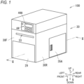
- an up-down direction 7 is defined with reference to a state where an image recording device 100 is usable (a state in FIG. 1 )
- a front-rear direction 8 is defined with a side where a discharge port 33 is provided as a front side (a front surface)
- a left-right direction 9 is defined when the image recording device 100 is viewed from the front side (the front surface).
- the image recording device 100 (an example of an ink ejection device) shown in FIG. 1 records an image on a sheet S forming a roll body 37 (see FIG. 2 ) using an inkjet recording method.
- the image recording device 100 includes a housing 30.
- the housing 30 has a substantially rectangular parallelepiped shape as a whole.
- a frame for supporting each member may be appropriately provided inside the housing 30.
- the slit-shaped discharge port 33 that is long in the left-right direction 9 is formed in a front surface 30F of the housing 30.
- the image-recorded sheet S (see FIG. 2 ) is discharged from the discharge port 33.
- An operation panel 44 is provided on the front surface 30F. A user performs an input on the operation panel 44 to operate the image recording device 100 or confirm various settings.
- a right cover 35A is located on a right surface 30R of the housing 30. By opening and closing the right cover 35A, a holder 35 and the like (see FIG. 2 ) located in a sheet storage space 32C are exposed or shielded.
- a front cover 29 is located on the front surface 30F of the housing 30.
- the front cover 29 can be opened around a pivot shaft (not shown) extending in the left-right direction 9 in the vicinity of a lower end of the front cover 29 such that an upper end side of the front cover 29 falls forward.
- a cartridge mounting portion 110 and the like located in an internal space 31 of the housing 30 are exposed or shielded.
- the holder 35, a tensioner 45, a conveyance roller pair 36, a conveyance roller pair 40, a head 38, a platen 51, a heater 39, a CIS 25, a cutter unit 26, the cartridge mounting portion 110, and the like are arranged in the internal space 31 of the housing 30.
- a fixing unit, an image sensor, a maintenance mechanism, and the like may be located in the internal space 31.
- a partition wall 41 is provided in the internal space 31.
- the partition wall 41 partitions a rear lower portion of the internal space 31 to define the sheet storage space 32C.
- the sheet storage space 32C is a space surrounded by the partition wall 41 and a lower housing 32 and isolated from the head 38 and the like.
- the roll body 37 is stored in the sheet storage space 32C.
- the roll body 37 includes a core tube and the long sheet S.
- the sheet S is wound around the core tube in a roll shape in a circumferential direction of a shaft core of the core tube.
- the sheet S is a non-absorbing medium having a surface with low water absorbability.
- the sheet S refers to a sheet whose water absorption amount from the start of contact to 30 msec 1/2 is 10 mL/m 2 or less in a Bristow method.
- msec 1/2 refers to the square root of msec.
- non-absorbing may refer to a water absorption rate of less than 0.5% in 24 hours measured in accordance with ASTM D570.
- non-absorbing may refer to the water absorption rate of less than 0.2%.
- a unit “%" of the water absorption rate is based on mass.
- examples of a material of the sheet S include plastics (such as polypropylene, polyethylene, polyethylene terephthalate, polyvinyl chloride resin, and polycarbonate).
- the tensioner 45 is located above the partition wall 41 in a rear portion of the internal space 31.
- the tensioner 45 has an outer circumferential surface 45A facing an outside of the lower housing 32.
- the outer circumferential surface 45A has a size equal to or larger than a maximum width of the sheet in the left-right direction 9, and has a shape that is symmetrical with respect to a sheet passing center (a center of the sheet S in the left-right direction 9).
- An upper end of the outer circumferential surface 45A is located at substantially the same up-down position as a nip position of the conveyance roller pair 36 in the up-down direction 7.
- the sheet S pulled out from the roll body 37 is hung and abutted on the outer circumferential surface 45A.
- the sheet S is curved forward along the outer circumferential surface 45A, extends in a conveyance orientation 8A, and is guided to the conveyance roller pair 36.
- the conveyance orientation 8A is a forward orientation along the front-rear direction 8.
- the tensioner 45 applies tension to the sheet S using a well-known method.
- the conveyance roller pair 36 is located in the front of the tensioner 45.
- the conveyance roller pair 36 includes a conveyance roller 36A and a pinch roller 36B.
- the conveyance roller 36A and the pinch roller 36B abut against each other at substantially the same up-down position as the upper end of the outer circumferential surface 45A.
- the conveyance roller pair 36 is an example of a conveyance device.
- the conveyance roller pair 40 is located in the front of the conveyance roller pair 36.
- the conveyance roller pair 40 includes a conveyance roller 40A and a pinch roller 40B.
- the conveyance roller 40A and the pinch roller 40B abut against each other at substantially the same up-down position as the upper end of the outer circumferential surface 45A.
- the conveyance rollers 36A and 40A are rotated by a driving force transmitted from a motor (not shown).
- the conveyance roller pair 36 rotates while nipping the sheet S extending from the tensioner 45 in the conveyance orientation 8A, thereby feeding the sheet S in the conveyance orientation 8A along a conveyance surface 43A.
- the conveyance roller pair 40 rotates while nipping the sheet S fed from the conveyance roller pair 36, thereby feeding the sheet S in the conveyance orientation 8A.
- the sheet S is pulled out from the sheet storage space 32C toward the tensioner 45 through a gap 42 by the rotation of the conveyance roller pairs 36 and 40.
- a conveyance path 43 extending from the upper end of the outer circumferential surface 45A to the discharge port 33 is formed in the internal space 31.
- the conveyance path 43 extends substantially linearly along the conveyance orientation 8A, and is a space through which the sheet S can pass.
- the conveyance surface 43A is indicated by a two-dot chain line indicating the conveyance path 43.
- the conveyance path 43 is defined by a guide member (not shown), the head 38, the platen 51, and the like, which are located apart from each other in the up-down direction 7.
- the head 38 is located above the conveyance path 43 and downstream of the conveyance roller pair 36 in the conveyance orientation 8A.
- the head 38 includes a frame 48 and ejection modules 49 each including a plurality of nozzles 38A.
- the ejection module 49 is supported by the frame 48.
- the ejection module 49 includes an inflow port 22 and an outflow port 23.
- the inflow port 22 and the outflow port 23 are connected to a manifold 24.
- the manifold 24 is connected to the plurality of nozzles 38A (see FIG. 3 ).
- the plurality of nozzles 38A eject an aqueous ink supplied from an ink sub-tank 181 (see FIG. 3 ) downward toward the sheet S supported by a conveyance belt 101. Accordingly, an image is recorded on the sheet S.
- the platen 51 is located below the conveyance path 43 and downstream of the conveyance roller pair 36 in the conveyance orientation 8A.
- the platen 51 is located below the head 38 and faces the head 38.
- the platen 51 includes the conveyance belt 101 and a support portion 104.
- the conveyance belt 101 supports the sheet S, which is conveyed in the conveyance orientation 8A by the conveyance roller pair 36 and is located directly below the head 38.
- the conveyance belt 101 conveys the supported sheet S in the conveyance orientation 8A.
- the heater 39 is located below the conveyance path 43, downstream of the head 38 in the conveyance orientation 8A, and upstream of the conveyance roller pair 40 in the conveyance orientation 8A.
- the heater 39 heats the sheet S conveyed through the conveyance path 43.
- the CIS 25 is located above the conveyance path 43 and downstream of the conveyance roller pair 40 in the conveyance orientation 8A.
- the CIS 25 reads the image on a printing surface of the sheet.
- the cutter unit 26 is located above the conveyance path 43 and downstream of the CIS 25 in the conveyance orientation 8A.
- the cutter unit 26 includes a cutter 28 mounted on a cutter carriage 27. As the cutter 28 moves, the sheet S located on the conveyance path 43 is cut along the left-right direction 9.
- the cartridge mounting portion 110 is located in the vicinity of a front end and a lower end of the housing 30, and has a box shape that opens toward the front.
- An ink cartridge 34 is inserted rearward into the cartridge mounting portion 110.
- An ink needle 112 extending forward is located on a rearward end surface 111 of the cartridge mounting portion 110. The ink needle 112 communicates with the ink sub-tank 181 through a flow path 182 (see FIG. 3 ).
- a contact point 114 is located on the end surface 111.
- the contact point 114 is electrically connected to an IC substrate 70 of the ink cartridge 34 in a state where the ink cartridge 34 is mounted on the cartridge mounting portion 110.
- the controller 130 can access a storage area of the IC substrate 70 through the contact point 114.
- the contact point 114 is electrically connected to an IC substrate 12 of a preservation liquid cartridge 11 in a state where the preservation liquid cartridge 11 is mounted on the cartridge mounting portion 110 (see FIG. 3 ).
- the controller 130 can access a storage area of the IC substrate 12 through the contact point 114.
- the ink cartridge 34 stores the aqueous ink. When the aqueous ink is consumed, the ink cartridge 34 is removed from the cartridge mounting portion 110 and replaced with a new ink cartridge 34 storing an aqueous ink.
- the IC substrate 70 is located on a rear surface of the ink cartridge 34. The IC substrate 70 stores identification information indicating the ink cartridge 34 in the storage area.
- the preservation liquid cartridge 11 (a second cartridge) is inserted into the cartridge mounting portion 110.
- the preservation liquid cartridge 11 stores a preservation liquid.
- the preservation liquid cartridge 11 is mounted on the cartridge mounting portion 110.
- the IC substrate 12 is located on a rear surface of the preservation liquid cartridge 11.
- the IC substrate 12 stores identification information indicating the preservation liquid cartridge 11 in the storage area.
- the ink circuit 113 includes the ink sub-tank 181, flow paths 182, 183, and 184, an atmospheric flow path 185, a replenishment valve 187, an atmospheric release valve 190, a positive pressure pump 191, and a liquid level sensor 192.
- the ink sub-tank 181 is located above the cartridge mounting portion 110 in the internal space 31 of the housing 30.
- the ink sub-tank 181 stores the aqueous ink in an internal space thereof.
- the internal space of the ink sub-tank 181 communicates with the ink needle 112 of the cartridge mounting portion 110 through the flow path 182.
- the ink stored in the ink cartridge 34 can flow into the ink sub-tank 181 through the flow path 182.
- the preservation liquid stored in the preservation liquid cartridge 11 can flow into the ink sub-tank 181 through the flow path 182.
- the replenishment valve 187 is located in the flow path 182.
- the replenishment valve 187 is controlled by the controller 130 to open and close the flow path 182.
- the flow path 183 is connected to the inflow port 22 of the ejection module 49.
- the flow path 184 is connected to the outflow port 23 of the ejection module 49.
- the aqueous ink or the preservation liquid stored in the internal space of the ink sub-tank 181 can be supplied to the ejection module 49 through the flow path 183.
- the positive pressure pump 191 is located in the flow path 183.
- the positive pressure pump 191 is operated by the controller 130 controlling driving of a pump motor 138 (see FIG. 4 ).
- a purge shutoff valve 188 is located in the flow path 184.
- the purge shutoff valve 188 is controlled by the controller 130 to open and close the flow path 184.
- a bypass flow path 186 is connected between the positive pressure pump 191 in the flow path 183 and the inflow port 22 and between the purge shutoff valve 188 in the flow path 184 and the ink sub-tank 181.
- a bypass valve 189 is located in the bypass flow path 186. The bypass valve 189 is controlled by the controller 130 to open and close the bypass flow path 186.
- the atmospheric release valve 190 is located in the atmospheric flow path 185.
- the atmospheric release valve 190 is controlled by the controller 130 to open and close the atmospheric flow path 185.
- the liquid level sensor 192 is located at the ink sub-tank 181.
- the liquid level sensor 192 detects the presence or absence of the aqueous ink at a replenishment liquid level height of the internal space of the ink sub-tank 181.
- the liquid level sensor 192 outputs a detection signal to the controller 130.
- the liquid level sensor 192 outputs an ON signal as a detection signal when the aqueous ink is detected, and outputs an OFF signal as a detection signal when the aqueous ink is not detected.
- the controller 130 determines whether a liquid level in the internal space of the ink sub-tank 181 reaches the replenishment liquid level height, based on the detection signal output from the liquid level sensor 192.
- a pressure reducing pump 193 is connected to the ink sub-tank 181.
- the pressure reducing pump 193 reduces a pressure in the internal space of the ink sub-tank 181 by discharging a gas in the internal space of the ink sub-tank 181 to the outside.
- a cap 62 is located below each ejection module 49. In FIG. 3 , only one ejection module 49 is shown.
- the cap 62 is made of an elastic body such as rubber or silicon.
- the cap 62 has a box shape with an open top.
- the cap 62 includes a discharge port 21 through which the aqueous ink or the like flows out from an internal space 67 of the cap 62.
- the discharge port 21 is connected to a waste liquid tank 77 through a flow path 178.
- a suction pump 74 is provided in the flow path 178. The suction pump 74 is driven by a suction pump motor 58 (see FIG. 4 ).
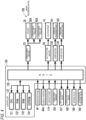
- the controller 130 includes a CPU 131, a ROM 132, a RAM 133, an EEPROM 134, and an ASIC 135, which are connected by an internal bus 137.
- the ROM 132 stores a program and the like for controlling various operations of the CPU 131.
- the RAM 133 is used as a storage area for temporarily storing data, signals, and the like used when the CPU 131 executes the program, or a work area for data processing.
- the EEPROM 134 stores settings, flags, aqueous ink supply date and time, the number of times of supply and discharge corresponding to an elapsed time, and the like, which are to be retained even after a power source is turned off.
- the number of times of supply and discharge is set in advance such that the number of times of supply and discharge increases as the elapsed time increases in units of time, for example.
- a conveyance motor 53, the suction pump motor 58, and pump motors 138 and 139 are connected to the ASIC 135.
- the replenishment valve 187, the purge shutoff valve 188, and the atmospheric release valve 190 are connected to the ASIC 135.
- Each valve is connected to the ASIC 135 via a drive circuit for driving the valve.
- the ASIC 135 generates a drive signal for rotating each motor, and controls the motor based on the drive signal.
- the motor rotates forward or backward according to the drive signal from the ASIC 135.
- the controller 130 controls driving of the conveyance motor 53 to rotate the holder 35, the conveyance roller 36A, and the conveyance roller 40A.
- the controller 130 controls the driving of the suction pump motor 58 to drive the suction pump 74.
- the controller 130 controls the driving of the pump motor 138 to drive the positive pressure pump 191.
- the controller 130 controls driving of the pump motor 139 to drive the pressure reducing pump 193.
- the operation panel 44, a display portion 44A, the contact point 114, the liquid level sensor 192, and a piezoelectric element are connected to the ASIC 135.
- the operation panel 44 outputs an operation signal corresponding to an operation of the user to the controller 130.
- the operation panel 44 may include, for example, a push button or a touch sensor superimposed on a display.
- the controller 130 performs reading or writing from or to the storage area of the IC substrate 70 of the ink cartridge 34 or the IC substrate 12 of the preservation liquid cartridge 11 through the contact point 114.
- the controller 130 receives the detection signal from the liquid level sensor 192.
- the piezoelectric element operates by being supplied with power from the controller 130 via a drive circuit (not shown).
- the controller 130 controls the power supply to the piezoelectric element, and causes ink droplets to be selectively ejected from the plurality of nozzles 38A.
- the aqueous ink contains water, a solvent group A, a binder polymer, a thickener, a coloring material, and a surfactant.
- the solvent group A, the binder polymer, the thickener, the coloring material, and the surfactant are dissolved or dispersed in water.
- the aqueous ink has a viscosity at 25°C in a range of 10 mPa ⁇ s to 14 mPa ⁇ s. The above range includes 10 mPa ⁇ s and 14 mPa ⁇ s. A viscosity of less than 10 mPa ⁇ s is not included in the above range.
- a viscosity exceeding 14 mPa ⁇ s is not included in the above range.
- the viscosity of the aqueous ink can be measured by, for example, a cone-plate rotational viscometer.
- the aqueous ink preferably has an evaporation rate of 70% or more when 5 g of the aqueous ink is placed in an upwardly opened container having a diameter of 60 mm and heated at 100°C for 4 hours indoors at a room temperature of 25°C and a humidity of 65%. The heating was performed by placing the container on the heater 39 and heating the container by the heater 39 such that a temperature in the container reached 100°C.
- the water is preferably ion-exchanged water or pure water.
- a weight percent of the water with respect to a total amount of the ink is in a range of 30.0 wt% to 60.0 wt%.
- the weight percent of the water may be, for example, a balance of the other components.
- the above range includes 30.0 wt% and 60.0 wt%.
- a weight percent of less than 30.0 wt% is not included in the above range.
- a weight percent exceeding 60.0 wt% is not included in the above range.
- the solvent group A is added to adjust a decapping property and a drying property of the aqueous ink.
- the decapping property refers to a property that the nozzle is less likely to be clogged due to the aqueous ink attached to the nozzle.
- the drying property refers to ease of drying of the aqueous ink.
- the solvent group A is a solvent having a vapor pressure of 0.07 Pa or more at 25°C.
- Examples of the solvent group A include tripropylene glycol (TPG) (vapor pressure: 0.7 Pa), propylene glycol (PG) (vapor pressure: 10.6 Pa), 1,5-pentanediol (vapor pressure: 0.52 Pa), 1,3-propylene glycol (4.5 Pa), 1,2-butanediol (vapor pressure: 10.0 Pa), 1,3-butanediol (vapor pressure: 8.0 Pa), 1,4-butanediol (vapor pressure: 1.0 Pa), and 3-methyl-1,5-pentanediol (MPD) (vapor pressure: 0.072 Pa).
- TPG tripropylene glycol
- PG propylene glycol
- PG propylene glycol
- 1,5-pentanediol vapor pressure: 0.52 Pa
- 1,3-propylene glycol 4.5 Pa
- 1,2-butanediol vapor pressure: 10.0 Pa
- 1,3-butanediol vapor pressure: 8.0 Pa
- the solvent group A contains tripropylene glycol and propylene glycol.
- the solvent group A is present in the aqueous ink in a weight percent of 31.0 wt% to 55.0 wt% with respect to the total amount of the aqueous ink.
- the above range includes 31.0 wt% and 55.0 wt%.
- a weight percent of less than 31.0 wt% is not included in the above range.
- a weight percent exceeding 55.0 wt% is not included in the above range.
- the binder polymer forms a coated film on the sheet S when the aqueous ink is dried.
- the binder polymer include an acrylic acid resin, a maleic acid ester resin, a vinyl acetate resin, a carbonate resin, a polycarbonate resin, a styrene resin, an ethylene resin, a polyethylene resin, a propylene resin, a polypropylene resin, a urethane resin, a polyurethane resin, a polyester resin, and a copolymer resin thereof, and an acrylic resin is preferred.
- the binder polymer is an acrylic polymer containing an acrylic acid as a monomer.
- the acrylic polymer is available, for example, from a low viscosity binder polymer dispersion liquid (Mowinyl 6969D, manufactured by Japan Coating Resin Co., Ltd.) or a high viscosity binder polymer dispersion liquid (Mowinyl 6775, Mowinyl 6960, Mowinyl 6899D, RA-071B1, RA-071B2, manufactured by Japan Coating Resin Co., Ltd.).
- a low viscosity binder polymer dispersion liquid Mowinyl 6969D, manufactured by Japan Coating Resin Co., Ltd.
- a high viscosity binder polymer dispersion liquid Mowinyl 6775, Mowinyl 6960, Mowinyl 6899D, RA-071B1, RA-071B2, manufactured by Japan Coating Resin Co., Ltd.
- the low viscosity binder polymer dispersion liquid has a viscosity at 25°C of 10 mPa ⁇ s or more and less than 100 mPa ⁇ s when being added to a low viscosity binder polymer dispersion medium such that the acrylic polymer is 38.0 wt% in the low viscosity binder polymer dispersion liquid.
- the acrylic polymer added to the low viscosity binder polymer dispersion medium may be referred to as a low viscosity acrylic polymer for convenience.
- the high viscosity binder polymer dispersion liquid has a viscosity at 25°C of 100 mPa ⁇ s or more and less than 5000 mPa s when being added to a high viscosity binder polymer dispersion medium such that the acrylic polymer is 38.0 wt% in the high viscosity binder polymer dispersion liquid.
- the viscosity of the high viscosity binder polymer dispersion liquid is preferably in a range of 2000 mPa ⁇ s to 5000 mPa ⁇ s. The above range includes 2000 mPa ⁇ s and 5000 mPa ⁇ s. A viscosity of less than 2000 mPa ⁇ s is not included in the above range.
- a viscosity exceeding 5000 mPa ⁇ s is not included in the above range.
- the acrylic polymer added to the high viscosity binder polymer dispersion medium may be referred to as a high viscosity acrylic polymer for convenience.
- the high viscosity acrylic polymer is the same as the low viscosity acrylic polymer.
- a weight percent of the high viscosity acrylic polymer with respect to the total amount of the aqueous ink is preferably 4.2 wt% or less.
- the thickener is added to increase the viscosity of the aqueous ink.
- the thickener is a liquid having a viscosity at 25°C of 44 mPa ⁇ s or more when being mixed with water at 80.0 wt%.
- the thickener contains the high viscosity binder polymer dispersion liquid and a solvent group B.
- the high viscosity binder polymer dispersion liquid contains the acrylic polymer, and thus also serves as the binder polymer.
- a low viscosity acrylic polymer dispersion liquid does not function as the thickener.
- the solvent group B is a solvent having a vapor pressure of less than 0.07 Pa at 25°C.
- Examples of the solvent group B include glycerin (vapor pressure: 0.01 Pa) and diglycerin (vapor pressure: less than 0.01 Pa).
- the solvent group B is a concept including one or more (for example, one or two) solvents among these solvents.
- the thickener is present in the aqueous ink in a weight percent of 13.0 wt% or less with respect to the total amount of the aqueous ink.
- the solvent group B is present in the aqueous ink in a weight percent of 3.0 wt% or less with respect to the total amount of the aqueous ink.
- the coloring material is, for example, a pigment that can be dispersed in water by a pigment dispersing resin (a resin dispersant).
- a pigment dispersing resin a resin dispersant
- examples of the coloring material include carbon black, an inorganic pigment, and an organic pigment.
- examples of the carbon black include furnace black, lamp black, acetylene black, and channel black.
- examples of the inorganic pigment include titanium oxide, an iron oxide inorganic pigment, and a carbon black inorganic pigment.
- the organic pigment examples include an azo pigment such as azo lake, an insoluble azo pigment, a condensed azo pigment, and a chelate azo pigment; a polycyclic pigment such as a phthalocyanine pigment, a perylene and perinone pigment, an anthraquinone pigment, a quinacridone pigment, a dioxazine pigment, a thioindigo pigment, an isoindolinone pigment, and a quinophthalone pigment; a dye lake pigment such as a basic dye lake pigment and an acid dye lake pigment; a nitro pigment; a nitroso pigment; and an aniline black daylight fluorescent pigment.
- the resin dispersant may be, for example, a general polymer dispersant (the pigment dispersing resin), or may be independently adjusted.
- a weight percent of the coloring material in the total amount of the aqueous ink is not particularly limited, and can be appropriately determined depending on, for example, a desired optical density or chroma.
- the weight percent of the coloring material is, for example, preferably in a range of 0.1 wt% or more and 20.0 wt% or less, and more preferably in a range of 1.0 wt% or more and 15.0 wt% or less.
- the weight percent of the coloring material is a weight of only the pigment, and does not include a weight of the binder polymer.
- the coloring material may be used alone or in combination of two or more thereof.
- the surfactant may further contain a cationic surfactant, an anionic surfactant, or a nonionic surfactant.
- these surfactants for example, commercially available products may be used. Examples of the commercially available products include “Olfine (registered trademark) E1010", “Olfine (registered trademark) E1006", “Olfine (registered trademark) E1004", “Silface SAG 503A”, and “Silface SAG 002", which are manufactured by Nissin Chemical Industry Co., Ltd.
- a weight percent of the surfactant in the total amount of the aqueous ink is, for example, 5.0 wt% or less, 3.0 wt% or less, or 0.1 wt% to 2.0 wt%.
- the aqueous ink may further contain an additive known in the related art, as necessary.
- the additive include a pH adjusting agent, a viscosity adjusting agent, a surface tension adjusting agent, a preservative, an antifungal agent, a leveling agent, an antifoaming agent, a light stabilizer, an antioxidant, a nozzle drying inhibitor, a polymer component such as an emulsion, and a dye.
- the viscosity adjusting agent include polyvinyl alcohol, cellulose, and a water-soluble resin.
- the aqueous ink can be prepared, for example, by uniformly mixing the water, the solvent group A, the binder polymer, the thickener, the coloring material, and the surfactant with other additives as necessary by a method known in the related art, and removing an insoluble matter by a filter or the like.
- the controller 130 executes a process (an image recording process) at the time of recording an image on the sheet S using the image recording device 100.
- the controller 130 executes the image recording process. Specifically, the controller 130 drives the conveyance motor 53 to drive the holder 35, the conveyance roller 36A, and the conveyance roller 40A. Accordingly, the sheet S is pulled out from the roll body 37 and conveyed in the conveyance orientation 8A. When the sheet S reaches a position directly below the head 38, the controller 130 causes the aqueous ink to be ejected from the nozzles 38A. Accordingly, an image is recorded on the sheet S.
- the aqueous ink attached to the sheet S is dried by being heated when passing through the heater 39. As a result, a coated film of the binder polymer is formed, and the aqueous ink is fixed to the sheet S.
- the sheet S passing through the heater 39 is further conveyed in the conveyance orientation 8A by the conveyance roller pair 40.
- the sheet S conveyed in the conveyance orientation 8A by the conveyance roller pair 40 is cut to a predetermined size by the cutter unit 26 and discharged.
- the controller 130 returns a leading end of the sheet S to a position of the conveyance roller pair 36 by reversely rotating the conveyance motor 53. The controller 130 repeatedly executes the above process until the image to be recorded is recorded on the sheet S.
- the controller 130 periodically executes a purge process (for example, when an image is recorded on 100 sheets S). Specifically, first, as shown in FIG. 3 , the controller 130 opens the purge shutoff valve 188 and the bypass valve 189 and closes the replenishment valve 187 and the atmospheric release valve 190 in a state where the cap 62 covers a nozzle surface 50. Next, the controller 130 drives the suction pump motor 58 to drive the suction pump 74. Accordingly, the aqueous ink in the nozzle 38A is suctioned, and the aqueous ink is discharged from the internal space 67 of the cap 62 to the waste liquid tank 77 through the discharge port 21 and the flow path 178.
- a purge process for example, when an image is recorded on 100 sheets S. Specifically, first, as shown in FIG. 3 , the controller 130 opens the purge shutoff valve 188 and the bypass valve 189 and closes the replenishment valve 187 and the atmospheric release valve 190 in a state where the cap 62 covers a
- the weight percent of the solvent group A with respect to the total amount of the aqueous ink is 31.0 wt% or more, the weight percent of the water which is more easily evaporated than the solvent group A is small. Therefore, the aqueous ink attached to the nozzle is prevented from drying quickly, and thus the aqueous ink is less likely to solidify. Accordingly, clogging of the nozzle due to the solidified ink is prevented. That is, the decapping property is ensured. Since the weight percent of the solvent group A with respect to the total amount of the aqueous ink is 55.0 wt% or less, the weight percent of the water which is more easily evaporated than the solvent group A is increased.
- the ink is easily dried quickly, and thus the drying property is ensured. Since the viscosity of the aqueous ink is adjusted to 10 mPa ⁇ s or more by the thickener, the image formed by the aqueous ink is less likely to become unclear. Therefore, image sharpness is ensured. Since the viscosity of the aqueous ink is adjusted to 14 mPa ⁇ s or less by the thickener, difficulty in ejecting the aqueous ink from the nozzle 38A is reduced. Therefore, an ejection property of the aqueous ink is ensured.
- the aqueous ink contains two different solvents, and when a solvent having a hydrophobic group is selected, solubility of a hydrophobic surfactant is high.
- the weight percent of the solvent group B with respect to the total amount of the aqueous ink is 3.0 wt% or less. Therefore, since the weight percent of the solvent group B which is less likely to be evaporated than the solvent group A is small, the drying property of the aqueous ink is high.
- the aqueous ink contains the high viscosity binder polymer dispersion liquid having the viscosity at 25°C of 100 mPa ⁇ s or more and less than 5000 mPa ⁇ s when being added to the high viscosity binder polymer dispersion medium such that the acrylic polymer is 38.0 wt% in the high viscosity binder polymer dispersion liquid. Therefore, the coated film formed by the binder polymer has a high rubbing resistance.
- the weight percent of the high viscosity acrylic polymer with respect to the total amount of the aqueous ink is 4.2 wt% or less, and thus when the aqueous ink is dried, coating film formation of the high viscosity acrylic polymer on the nozzle surface 50 or in the nozzle 38A is prevented. Therefore, an ejection failure of the aqueous ink is prevented.
- the binder polymer is an acrylic polymer
- the coated film formed by the binder polymer has high rubbing resistance and stability.
- the aqueous ink has a high drying property because the evaporation rate is 70% or more when 5 g of the aqueous ink is placed in the upwardly opened container having the diameter of 60 mm and heated for 4 hours indoors at the room temperature of 25°C and the humidity of 65%.
- the aqueous ink attached to the sheet S is heated when passing through the heater 39, the aqueous ink attached to the sheet S is easily dried.
- a heating temperature of the heater 39 is 60°C or higher, the aqueous ink attached to the sheet S is easily dried.
- the viscosity at 25°C of the aqueous ink is as high as 10 mPa ⁇ s or more. Therefore, even when a distance between the head 38 and the sheet S in the up-down direction 7 is increased and the aqueous ink is ejected downward from the nozzle 38A, the aqueous ink is less likely to spread on the sheet S, and thus the image formed by the aqueous ink is less likely to become unclear. Therefore, a size restriction on a printing target is easily reduced by increasing the distance between the head 38 and the sheet S in the up-down direction 7.
- the purge process of driving the suction pump 74 is periodically executed in a state where the cap 62 covers the nozzle 38A, and thus the nozzle 38A is less likely to be clogged by a foreign matter.
- the sheet S is conveyed by the conveyance roller pair 36 to a position facing the head 38 in the up-down direction 7, and thus the image is suitably recorded on the sheet S.
- the aqueous ink is ejected downward from the nozzle 38A, but the aqueous ink may be ejected in a horizontal direction from the nozzle 38A.
- the head 38 is disposed such that the nozzle surface 50 is oriented perpendicular to the horizontal direction. Even when the aqueous ink is ejected in the horizontal direction from the nozzle 38A, dripping of the aqueous ink attached to the sheet S is less likely to occur because the viscosity of the aqueous ink is as high as 10 mPa ⁇ s or more.
- the sheet S is the non-absorbing medium having the surface with low water absorbability, but may be an absorbing medium having a surface with high water absorbability.
- the absorbing medium include plain paper, glossy paper, and matte paper.
- the purge process is periodically executed during the image recording process, but the purge process may not be executed.
- the ink cartridge 34 and the preservation liquid cartridge 11 are separate and replaced with respect to the cartridge mounting portion 110, but the ink cartridge 34 and the preservation liquid cartridge 11 may be integrally formed and mounted on the cartridge mounting portion 110.
- a viscosity of the aqueous ink is 13.2 mPa ⁇ s at 25°C.
- the low viscosity acrylic polymer was obtained from a low viscosity acrylic polymer dispersion liquid (Mowinyl 6969D, manufactured by Japan Coating Resin Co., Ltd.).
- compositions were the same as those of Example 1 except that 39.1 wt% of pure water as the water, and 3.0 wt% of tripropylene glycol, 25.0 wt% of propylene glycol, and 21.5 wt% of 1,5-pentanediol as the solvent group A were used.
- a viscosity of an aqueous ink is 12.2 mPa ⁇ s at 25°C.
- compositions were the same as those of Example 1 except that 33.6 wt% of pure water as the water and 55.0 wt% ofpropylene glycol as the solvent group A were used.
- a viscosity of an aqueous ink is 13.9 mPa ⁇ s at 25°C.
- compositions were the same as those of Example 1 except that 38.6 wt% of pure water as the water and 50.0 wt% of propylene glycol as the solvent group A were used.
- a viscosity of an aqueous ink is 11.4 mPa ⁇ s at 25°C.
- compositions were the same as those of Example 1 except that 33.6 wt% of pure water as the water, 55.0 wt% of propylene glycol as the solvent group A, and 3.0 wt% of glycerin as a solvent group B were used.
- a viscosity of an aqueous ink is 13.0 mPa ⁇ s at 25°C.
- compositions were the same as those of Example 1 except that 35.6 wt% of pure water as the water, 50.0 wt% of propylene glycol as the solvent group A, and 3.0 wt% of glycerin as the solvent group B were used.
- a viscosity of an aqueous ink is 13.1 mPa ⁇ s at 25°C.
- compositions were the same as those of Example 1 except that 51.7 wt% of pure water as the water, 4.2 wt% of a high viscosity acrylic polymer as the binder polymer, 31.0 wt% of propylene glycol as the solvent group A, and 11.0 wt% of a high viscosity binder polymer dispersion liquid (Mowinyl 6775, manufactured by Japan Coating Resin Co., Ltd.) as a thickener were used.
- a viscosity of an aqueous ink is 12.8 mPa ⁇ s at 25°C.
- a weight percent of the high viscosity binder polymer dispersion liquid is a sum of 4.2 wt% of a high viscosity acrylic polymer and 6.8 wt% of a high viscosity acrylic polymer dispersion medium.
- Table 1 the weight percent of the high viscosity acrylic polymer dispersion medium was shown in order to make it easy to understand that the total is 100 wt%.
- compositions were the same as those of Example 1 except that 49.7 wt% of pure water as the water, 3.8 wt% of a high viscosity acrylic polymer as the binder polymer, 31.0 wt% of propylene glycol as the solvent group A, 3.0 wt% of glycerin as the solvent group B, and 10.0 wt% of a high viscosity binder polymer dispersion liquid as the thickener were used.
- a viscosity of an aqueous ink is 13.3 mPa ⁇ s at 25°C.
- a weight percent of the high viscosity binder polymer dispersion liquid is a sum of 3.8 wt% of a high viscosity acrylic polymer and 6.2 wt% of a high viscosity acrylic polymer dispersion medium.
- compositions were the same as those of Example 1 except that 45.4 wt% of pure water as the water, 48.0 wt% of tripropylene glycol as the solvent group A, 1.0 wt% of a low viscosity acrylic polymer as the binder polymer, and 3.0 wt% of carbon black as the coloring material were used.
- a viscosity of an aqueous ink is 12.5 mPa ⁇ s at 25°C.
- compositions were the same as those of Example 1 except that 49.6 wt% of pure water as the water, 31.0 wt% of tripropylene glycol as the solvent group A, and 10.0 wt% of a low viscosity acrylic polymer as the binder polymer were used.
- a viscosity of an aqueous ink is 12.3 mPa ⁇ s at 25°C.
- compositions were the same as those of Example 1 except that 38.4 wt% of pure water as the water, 55.0 wt% of 1,5-pentanediol as the solvent group A, 1.0 wt% of a low viscosity acrylic polymer as the binder polymer, and 3.0 wt% of carbon black as the coloring material were used.
- a viscosity of an aqueous ink is 13.9 mPa ⁇ s at 25°C.
- compositions were the same as those of Example 1 except that 51.8 wt% of pure water as the water, 3.0 wt% of a high viscosity acrylic polymer as the binder polymer, 31.0 wt% of 1,5-pentanediol as the solvent group A, 3.0 wt% of glycerin as the solvent group B, and 7.9 wt% of a high viscosity binder polymer dispersion liquid as the thickener were used.
- a viscosity of an aqueous ink is 12.8 mPa s at 25°C.
- a weight percent of the high viscosity binder polymer dispersion liquid is a sum of 3.0 wt% of a high viscosity acrylic polymer and 4.9 wt% of a high viscosity acrylic polymer dispersion medium.
- compositions were the same as those of Example 1 except that 37.6 wt% of pure water as the water, 2.0 wt% of a low viscosity acrylic polymer as the binder polymer, and 3.0 wt% of glycerin as the solvent group B were used.
- a viscosity of an aqueous ink is 11.4 mPa ⁇ s at 25°C.
- compositions were the same as those of Example 1 except that 37.6 wt% of pure water as the water, 2.0 wt% of low viscosity polyethylene (ARROWBASE SB-1030N manufactured by UNITIKA LTD.) as the binder polymer, and 3.0 wt% of glycerin as the solvent group B were used.
- a viscosity of an aqueous ink is 11.9 mPa ⁇ s at 25°C.
- compositions were the same as those of Example 1 except that 33.6 wt% of pure water as the water and 55.0 wt% of 1,3-propylene glycol as the solvent group A were used.
- a viscosity of an aqueous ink is 13.1 mPa ⁇ s at 25°C.
- compositions were the same as those of Example 1 except that 40.6 wt% of pure water as the water and 48.0 wt% of 1,2-butanediol as the solvent group A were used.
- a viscosity of an aqueous ink is 11.7 mPa ⁇ s at 25°C.
- compositions were the same as those of Example 1 except that 41.6 wt% of pure water as the water and 47.0 wt% of 1,3-butanediol as the solvent group A were used.
- a viscosity of an aqueous ink is 13.6 mPa s at 25°C.
- compositions were the same as those of Example 1 except that 40.6 wt% of pure water as the water and 48.0 wt% of 1,4-butanediol as the solvent group A were used.
- a viscosity of an aqueous ink is 12.3 mPa s at 25°C.
- compositions were the same as those of Example 1 except that 43.6 wt% of pure water as the water and 45.0 wt% of 3-methyl-1,5-pentanediol as the solvent group A were used.
- a viscosity of an aqueous ink is 12.8 mPa ⁇ s at 25°C.
- compositions were the same as those of Example 1 except that 45.2 wt% of pure water as the water, 8.4 wt% of a low viscosity acrylic polymer as the binder polymer, and 11.0 wt% of tripropylene glycol and 29.0 wt% of propylene glycol as the solvent group A were used.
- a viscosity of an aqueous ink is 11.1 mPa ⁇ s at 25°C.
- compositions were the same as those of Example 1 except that 37.6 wt% of pure water as the water, 2.0 wt% of polyurethane as the binder polymer, and 3.0 wt% of glycerin as the solvent group B were used.
- a viscosity of an aqueous ink is 12.2 mPa ⁇ s at 25°C.
- compositions were the same as those of Example 1 except that 51.4 wt% of pure water as the water, 4.3 wt% of a high viscosity acrylic polymer as the binder polymer, 31.0 wt% of propylene glycol as the solvent group A, and 11.3 wt% of a high viscosity binder polymer dispersion liquid as the thickener were used.
- a viscosity of an aqueous ink is 13.5 mPa s at 25°C.
- a weight percent of the high viscosity binder polymer dispersion liquid is a sum of 4.3 wt% of a high viscosity acrylic polymer and 7.0 wt% of a high viscosity acrylic polymer dispersion medium.
- compositions were the same as those of Example 1 except that 51.6 wt% of pure water as the water, 8.0 wt% of a low viscosity acrylic polymer as the binder polymer, 31.0 wt% of tripropylene glycol as the solvent group A, and 3.0 wt% of glycerin as the solvent group B were used.
- a viscosity of an aqueous ink is 10.4 mPa ⁇ s at 25°C.
- compositions were the same as those of Example 1 except that 54.4 wt% of pure water as the water, 2.0 wt% of a high viscosity acrylic polymer as the binder polymer, 31.0 wt% of 1,5-pentanediol as the solvent group A, 3.0 wt% of glycerin as the solvent group B, and 5.3 wt% of a high viscosity binder polymer dispersion liquid as the thickener were used.
- a viscosity of an aqueous ink is 10.2 mPa s at 25°C.
- a weight percent of the high viscosity binder polymer dispersion liquid is a sum of 2.0 wt% of a high viscosity acrylic polymer and 3.3 wt% of a high viscosity acrylic polymer dispersion medium.
- compositions were the same as those of Example 1 except that 53.9 wt% of pure water as the water, 2.2 wt% of a high viscosity acrylic polymer as the binder polymer, 31.0 wt% of 1,5-pentanediol as the solvent group A, 3.0 wt% of glycerin as the solvent group B, and 5.8 wt% of a high viscosity binder polymer dispersion liquid as the thickener were used.
- a viscosity of an aqueous ink is 10.6 mPa s at 25°C.
- a weight percent of the high viscosity binder polymer dispersion liquid is a sum of 2.2 wt% of a high viscosity acrylic polymer and 3.6 wt% of a high viscosity acrylic polymer dispersion medium.
- compositions were the same as those of Example 1 except that 54.4 wt% of pure water as the water, 2.2 wt% of a high viscosity acrylic polymer as the binder polymer, 31.0 wt% of 1,5-pentanediol as the solvent group A, 1.5 wt% of glycerin and 1.0 wt% of diglycerin as the solvent group B, and 5.8 wt% of a high viscosity binder polymer dispersion liquid as the thickener were used.
- a viscosity of an aqueous ink is 10.8 mPa s at 25°C.
- a weight percent of the high viscosity binder polymer dispersion liquid is a sum of 2.2 wt% of a high viscosity acrylic polymer and 3.6 wt% of a high viscosity acrylic polymer dispersion medium.
- compositions were the same as those of Example 1 except that 39.1 wt% of pure water as the water, 3.0 wt% of tripropylene glycol and 25.0 wt% of propylene glycol as the solvent group A, and 21.5 wt% of glycerin as the solvent group B were used.
- a viscosity of an aqueous ink is 12.7 mPa s at 25°C.
- compositions were the same as those of Comparative Example 1 except that 51.9 wt% of pure water as the water, 2.5 wt% of a low viscosity acrylic polymer and 2.6 wt% of a high viscosity acrylic polymer as the binder polymer, 8.6 wt% of glycerin as the solvent group B, and 6.9 wt% of a high viscosity binder polymer dispersion liquid as the thickener were used.
- a viscosity of an aqueous ink is 12.0 mPa s at 25°C.
- a weight percent of the high viscosity binder polymer dispersion liquid is a sum of 2.6 wt% of a high viscosity acrylic polymer and 4.3 wt% of a high viscosity acrylic polymer dispersion medium.
- compositions were the same as those of Comparative Example 1 except that 21.5 wt% of diglycerin as the solvent group B was used.
- a viscosity of an aqueous ink is 15.4 mPa ⁇ s at 25°C.
- compositions were the same as those of Comparative Example 1 except that 32.6 wt% of pure water as the water and 56.0 wt% of propylene glycol as the solvent group A were contained and the solvent group B was omitted.
- a viscosity of an aqueous ink is 14.6 mPa ⁇ s at 25°C.
- compositions were the same as those of Comparative Example 1 except that 58.6 wt% of pure water as the water, 3.0 wt% of tripropylene glycol and 27.0 wt% of propylene glycol as the solvent group A were contained and the solvent group B was omitted.
- a viscosity of an aqueous ink is 5.8 mPa ⁇ s at 25°C.
- compositions were the same as those of Comparative Example 1 except that 28.5 wt% of pure water as the water, 56.0 wt% of propylene glycol as the solvent group A, and 4.0 wt% of glycerin as the solvent group B were used.
- a viscosity of an aqueous ink is 17.8 mPa ⁇ s at 25°C.
- compositions were the same as those of Comparative Example 1 except that 54.6 wt% of pure water as the water, 30.0 wt% of propylene glycol as the solvent group A, and 4.0 wt% of glycerin as the solvent group B were used.
- a viscosity of an aqueous ink is 6.0 mPa ⁇ s at 25°C.
- compositions were the same as those of Comparative Example 1 except that 28.6 wt% of pure water as the water, 56.0 wt% of tripropylene glycol as the solvent group A, and 4.0 wt% of glycerin as the solvent group B were used.
- a viscosity of an aqueous ink is 34.3 mPa ⁇ s at 25°C.
- compositions were the same as those of Comparative Example 1 except that 54.6 wt% of pure water as the water, 30.0 wt% of tripropylene glycol as the solvent group A, and 4.0 wt% of glycerin as the solvent group B were used.
- a viscosity of an aqueous ink is 8.2 mPa ⁇ s at 25°C.
- compositions were the same as those of Comparative Example 1 except that 38.4 wt% of pure water as the water, 1.0 wt% of a low viscosity acrylic polymer as the binder polymer, and 55.0 wt% of tripropylene glycol as the solvent group A were contained and the solvent group B was omitted.
- a viscosity of an aqueous ink is 17.8 mPa ⁇ s at 25°C.
- compositions were the same as those of Comparative Example 1 except that 48.4 wt% of pure water as the water, 1.0 wt% of a low viscosity acrylic polymer as the binder polymer, and 45.0 wt% of tripropylene glycol as the solvent group A were contained and the solvent group B was omitted.
- a viscosity of an aqueous ink is 10.6 mPa ⁇ s at 25°C.
- compositions were the same as those of Comparative Example 1 except that 48.7 wt% of pure water as the water, 4.2 wt% of a high viscosity acrylic polymer as the binder polymer, 31.0 wt% of propylene glycol as the solvent group A, 11.0 wt% of a high viscosity binder polymer dispersion liquid as the thickener, and 3.0 wt% of glycerin as the solvent group B were used.
- a viscosity of an aqueous ink is 15.1 mPa s at 25°C.
- a weight percent of the high viscosity binder polymer dispersion liquid is a sum of 4.2 wt% of a high viscosity acrylic polymer and 6.8 wt% of a high viscosity acrylic polymer dispersion medium.
- compositions were the same as those of Comparative Example 1 except that 33.6 wt% of pure water as the water and 55.0 wt% of tripropylene glycol as the solvent group A were contained and the solvent group B was omitted.
- a viscosity of an aqueous ink is 26.6 mPa ⁇ s at 25°C.
- compositions were the same as those of Comparative Example 1 except that 54.6 wt% of pure water as the water, 31.0 wt% of tripropylene glycol as the solvent group A, and 3.0 wt% of glycerin as the solvent group B were used.
- a viscosity of an aqueous ink is 8.4 mPa ⁇ s at 25°C.
- compositions were the same as those of Comparative Example 1 except that 33.6 wt% of pure water as the water and 55.0 wt% of 1,5-pentanediol as the solvent group A were contained and the solvent group B was omitted.
- a viscosity of an aqueous ink is 20.9 mPa ⁇ s at 25°C.
- compositions were the same as those of Comparative Example 1 except that 36.6 wt% of pure water as the water, 2.0 wt% of a low viscosity acrylic polymer as the binder polymer, and 55.0 wt% of 1,5-pentanediol as the solvent group A were contained and the solvent group B was omitted.
- a viscosity of an aqueous ink is 14.6 mPa ⁇ s at 25°C.
- compositions were the same as those of Comparative Example 1 except that 40.5 wt% of pure water as the water and 48.0 wt% of 1,3-propylene glycol as the solvent group A were contained and the solvent group B was omitted.
- a viscosity of an aqueous ink is 9.6 mPa ⁇ s at 25°C.
- compositions were the same as those of Comparative Example 1 except that 40.6 wt% of pure water as the water and 48.0 wt% of 1,3-butanediol as the solvent group A were contained and the solvent group B was omitted.
- a viscosity of an aqueous ink is 14.1 mPa s at 25°C.
- compositions were the same as those of Comparative Example 1 except that 40.6 wt% of pure water as the water and 48.0 wt% of 3-methyl-1,5-pentanediol as the solvent group A were contained and the solvent group B was omitted.
- a viscosity of an aqueous ink is 14.9 mPa ⁇ s at 25°C.
- compositions were the same as those of Comparative Example 1 except that 57.6 wt% of pure water as the water and 31.0 wt% of propylene glycol as the solvent group A were contained and the solvent group B was omitted.
- a viscosity of an aqueous ink is 5.3 mPa s at 25°C.
- compositions were the same as those of Comparative Example 1 except that 54.6 wt% of pure water as the water, 31.0 wt% of propylene glycol as the solvent group A, and 3.0 wt% of glycerin as the solvent group B were used.
- a viscosity of an aqueous ink is 5.9 mPa ⁇ s at 25°C.
- the head 38 was left for 30 minutes in a state where the nozzle surface 50 was not covered with the cap 62, it was visually determined whether printing on the sheet S could be performed by ejecting the aqueous ink from the nozzle 38A according to the following evaluation criteria.
- a non-absorbing medium for example, a resin film formed of polypropylene was used. A: No pin missing or twisting was observed at all. B: Some pin missing or twisting was observed. C: Many pin missing or twisting was observed.
- the aqueous ink was ejected from the nozzle 38A at a resolution of 600 ⁇ 600 dpi and a liquid droplet amount of about 17 pL to cause the aqueous ink to attach to the sheet S, and then the aqueous ink was heated at about 60°C for 10 minutes by an infrared wire heater, and thereafter was visually determined according to the following evaluation criteria.
- a non-absorbing medium for example, a resin film formed of polypropylene was used as the sheet S.
- B There is no stickiness when the coated film was touched with a finger.
- C There is a stickiness when the coated film was touched with a finger.
- D There is a disturbance when the coated film was touched with a finger.
- An image was recorded on the sheet S by ejecting the aqueous ink from the nozzle 38A, and an image quality was visually determined according to the following evaluation criteria.
- a non-absorbing medium for example, a resin film formed of polypropylene was used.
- An image was recorded on 100 sheets S by ejecting the aqueous ink from the nozzle 38A, and an image quality was visually determined according to the following evaluation criteria.
- a non-absorbing medium for example, a resin film formed of polypropylene was used.
- the aqueous ink was heated at a temperature of 60°C for 10 minutes by the heater 39 to form a coated film of the binder polymer on the sheet S.
- the coated film was rubbed with a cotton swab and visually determined according to the following evaluation criteria. A: No peeling of the coated film occurred at all. B: Slight peeling of the coated film occurred. C: Peeling of the coated film occurred.
- the head 38 was left for 30 minutes in a state where the nozzle surface 50 was not covered with the cap 62, and thereafter an image was recorded on the sheet S by ejecting the aqueous ink from the nozzle 38A, and an image quality was visually determined according to the following evaluation criteria.
- Examples 1 to 25 are evaluated as A or B, whereas Comparative Examples 1 to 3, 5, 7, and 9 are evaluated as C, and it is understood that Examples 1 to 25 have an excellent decapping property. In Examples 1 to 25, this is considered to be because the solvent group A contained in the aqueous ink was 31.0 wt% or more, and thus the weight percent of the water which is more easily evaporated than the solvent group A was reduced, and the aqueous ink attached to the nozzle 38A was not solidified much.
- Examples 1 to 26 are evaluated as A or B, whereas Comparative Examples 4, 6, and 8 are evaluated as D, and it is understood that Examples 1 to 26 have an excellent drying property.
- this is considered to be because the solvent group A contained in the aqueous ink was limited to 55.0 wt% or less, and thus the weight percent of the water which is more easily evaporated than the solvent group A was large.
- Comparative Examples 4, 6, and 8 this is considered to be because the solvent group A contained in the aqueous ink was 56.0 wt%, and thus the weight percent of the water which is more easily evaporated than the solvent group A was small.
- Example 5 When Example 5 was compared with Comparative Example 6, the solvent group B contained in the aqueous ink was 3.0 wt% in Example 5, whereas the solvent group B was 4.0 wt% in Comparative Example 6. It is considered that the weight percent of the solvent group B which is less likely to be evaporated than the solvent group A is smaller in Example 5, and thus the evaluation of the drying property was higher in Example 5.
- Examples 1 to 26 are evaluated as A or B, whereas Comparative Examples 5, 7, 9, 14, 17, 20, and 21 are evaluated as C, and it is understood that Examples 1 to 26 have excellent image sharpness.
- Examples 1 to 25 it is considered that the viscosity at 25°C of the aqueous ink was as high as 10.2 mPa ⁇ s or more, and thus a sharp image was obtained.
- Comparative Examples 5, 7, 9, 14, 17, 20, and 21 it is considered that the viscosity at 25°C of the aqueous ink was as low as 9.6 mPa ⁇ s or less, and thus the image was blurred overall.
- Examples 1 to 25 are evaluated as A and B, whereas Comparative Examples 3, 4, 6, 8, 10, 12, 13, 15, 16, 18, and 19 are evaluated as C, and it is understood that Examples 1 to 26 have an excellent first ejection property. In Examples 1 to 26, this is considered to be because the viscosity of the aqueous ink was as low as 13.9 mPa ⁇ s or less, and thus the aqueous ink was smoothly ejected from the nozzle 38A.
- Examples 7, 8, 12, 22, 24, and 25 are evaluated as A, whereas Examples other than these Examples are evaluated as B, and it is understood that coated films of Examples 7, 8, 12, 22, 24, and 25 have an excellent rubbing resistance. This is considered to be because the high viscosity acrylic polymer was used as the binder polymer in Examples 7, 8, 12, 22, 24, 25, and 26, whereas the low viscosity acrylic polymer was used as the binder polymer in Examples other than Examples 2 and 17.
- Example 7 8, 12, 24, and 25 are compared with Example 22, Examples 7, 8, 12, 24, and 25 are evaluated as A, whereas Example 22 is evaluated as B, and it is understood that Examples 7, 8, 12, 24, and 25 have an excellent second ejection property. This is considered to be because the high viscosity acrylic polymer was contained in the aqueous ink in an amount of 4.3 wt% in Example 22, whereas the high viscosity acrylic polymer was contained in the aqueous ink in an amount of 4.2 wt% or less in Examples 7, 8, 12, 24, and 25, and thus when the aqueous ink is dried, coating film formation of the high viscosity acrylic polymer on the nozzle surface 50 or in the nozzle 38A is prevented.
- Example 1 Example 2 Example 3
- Example 4 Example 5
- Example 6 Example 7
- Example 8 Solvent group A (wt%) TPG (vapor pressure: 0.7 Pa) 3.0 3.0 - - - - - - PG (vapor pressure: 10.6 Pa) 48.0 25.0 55.0 50.0 55.0 50.0 31.0 31.0 1,5-pentanediol (vapor pressure: 0.52 Pa) - 21.5 - - - - - - - 1,3-propylene glycol (vapor pressure: 4.5 Pa) - - - - - - - - 1,2-butanediol (vapor pressure: 10.0 Pa) - - - - - - - 1,3-butanediol (vapor pressure: 8.0 Pa) - - - - - - - 1,4-butanediol (vapor pressure: 1.0 Pa) - - - - - - - - MPD (vapor pressure:
- the present disclosure discloses at least the following disclosure.
- An aqueous ink includes water, a solvent group A having a vapor pressure of 0.07 Pa or more at 25°C, a thickener, and a binder polymer.
- the solvent group A is present in the aqueous ink in a weight percent of 31.0 wt% to 55.0 wt% with respect to a total amount of the aqueous ink.
- the thickener is present in the aqueous ink in a weight percent of 13.0 wt% or less with respect to the total amount of the aqueous ink.
- the aqueous ink has a viscosity of 10 mPa ⁇ s to 14 mPa ⁇ s at 25°C.
- the weight percent of the solvent group A with respect to the total amount of the aqueous ink is 31.0 wt% or more, a weight percent of the water which is more easily evaporated than the solvent group A is reduced. Therefore, the aqueous ink attached to a nozzle is prevented from drying quickly, and thus the aqueous ink is less likely to solidify. Accordingly, clogging of the nozzle due to the solidified ink is prevented. That is, a decapping property is ensured. Since the weight percent of the solvent group A with respect to the total amount of the aqueous ink is 55.0 wt% or less, the weight percent of the water which is more easily evaporated than the solvent group A is increased.
- the ink is easily dried quickly, and thus a drying property is ensured. Since the viscosity of the aqueous ink at 25°C is adjusted to 10 mPa ⁇ s or more by the thickener, an image formed by the aqueous ink is less likely to become unclear. Therefore, image sharpness is ensured. Since the viscosity of the aqueous ink at 25°C is adjusted to 14 mPa ⁇ s or less by the thickener, difficulty in ejecting the ink from the nozzle is reduced. Therefore, an ink ejection property is ensured.
Landscapes
- Chemical & Material Sciences (AREA)
- Engineering & Computer Science (AREA)
- Life Sciences & Earth Sciences (AREA)
- Materials Engineering (AREA)
- Wood Science & Technology (AREA)
- Organic Chemistry (AREA)
- Chemical Kinetics & Catalysis (AREA)
- General Chemical & Material Sciences (AREA)
- Environmental & Geological Engineering (AREA)
- Ink Jet (AREA)
- Inks, Pencil-Leads, Or Crayons (AREA)
Abstract
Description
- This application claims priority from
Japanese Patent Application No. 2023-031593 filed on March 2, 2023 Japanese Patent Application No. 2023-186300 filed on October 31, 2023 - As an aqueous ink used in an ink jet recording device, an aqueous ink for ink jet recording of a related art is known. The aqueous ink for ink jet recording of the related art contains water, a water-soluble organic solvent, a pH adjusting agent, a viscosity adjusting agent, a surface tension adjusting agent, an antifungal agent, and the like. In the related art, a viscosity of the ink is adjusted to be low so that the ink is easily ejected from a nozzle of an ink jet head.
- The above aqueous ink for ink jet recording has an excellent ink ejection property, but it is difficult to obtain a sharp image quality because the viscosity of the ink is low. This can lead to ragged edges. Therefore, in order to improve sharpness, it is conceivable to increase the viscosity beyond that of the above aqueous ink. However, this adjustment might deteriorate the ink ejection property, consume a large amount of solvent, and thus deteriorate a drying property of the ink depending on a type of the solvent and a solvent ratio. Moreover, a higher viscosity could cause the ink attached to the nozzle to dry quickly, increasing the likelihood of clogging, thus deteriorating a so-called decapping property.
- An object of the present disclosure is to provide an aqueous ink, an ink ejection device, an image recording device, and a printing method that an ink ejection property and image sharpness and also ensure a drying property and a decapping property.
- An aqueous ink according to one aspect of the present disclosure includes water, a solvent group A having a vapor pressure of 0.07 Pa or more at 25°C, a thickener, and a binder polymer. The solvent group A is present in the aqueous ink in a weight percent of31.0 wt% to 55.0 wt% with respect to a total amount of the aqueous ink . The thickener is present in the aqueous ink in a weight percent of 13.0 wt% or less with respect to the total amount of the aqueous ink . The aqueous ink has a viscosity of 10 mPa·s to 14 mPa s at 25°C.
- According to the present disclosure, the ink ejection property and the image sharpness are ensured, and the drying property and the decapping property are ensured.
-
- [
FIG. 1] FIG. 1 is an external perspective view of animage recording device 100 according to an embodiment of the present disclosure. - [
FIG. 2] FIG. 2 is a cross-sectional view taken along a line 11-11 inFIG. 1 . - [
FIG. 3] FIG. 3 is a schematic diagram showing anink circuit 113. - [
FIG. 4] FIG. 4 is a block diagram showing acontroller 130. - Hereinafter, a preferred embodiment of the present disclosure will be described. The present embodiment is merely one embodiment of the present disclosure, and it is needless to say that the embodiment can be modified without changing the gist of the present disclosure. In the following description, an advancement movement from a start point to an end point of an arrow is expressed as an "orientation", and a unidirectional or bidirectional movement along a line connecting the start point and the end point of the arrow is expressed as a "direction". In the following description, an up-down direction 7 is defined with reference to a state where an
image recording device 100 is usable (a state inFIG. 1 ), a front-rear direction 8 is defined with a side where adischarge port 33 is provided as a front side (a front surface), and a left-right direction 9 is defined when theimage recording device 100 is viewed from the front side (the front surface). - The image recording device 100 (an example of an ink ejection device) shown in
FIG. 1 records an image on a sheet S forming a roll body 37 (seeFIG. 2 ) using an inkjet recording method. - As shown in
FIG. 1 , theimage recording device 100 includes ahousing 30. Thehousing 30 has a substantially rectangular parallelepiped shape as a whole. A frame for supporting each member may be appropriately provided inside thehousing 30. - The slit-
shaped discharge port 33 that is long in the left-right direction 9 is formed in afront surface 30F of thehousing 30. The image-recorded sheet S (seeFIG. 2 ) is discharged from thedischarge port 33. Anoperation panel 44 is provided on thefront surface 30F. A user performs an input on theoperation panel 44 to operate theimage recording device 100 or confirm various settings. - A
right cover 35A is located on aright surface 30R of thehousing 30. By opening and closing theright cover 35A, aholder 35 and the like (seeFIG. 2 ) located in asheet storage space 32C are exposed or shielded. - A
front cover 29 is located on thefront surface 30F of thehousing 30. Thefront cover 29 can be opened around a pivot shaft (not shown) extending in the left-right direction 9 in the vicinity of a lower end of thefront cover 29 such that an upper end side of thefront cover 29 falls forward. By opening and closing thefront cover 29, acartridge mounting portion 110 and the like (seeFIG. 2 ) located in aninternal space 31 of thehousing 30 are exposed or shielded. - As shown in
FIG. 2 , theholder 35, atensioner 45, aconveyance roller pair 36, aconveyance roller pair 40, ahead 38, aplaten 51, aheater 39, aCIS 25, acutter unit 26, thecartridge mounting portion 110, and the like are arranged in theinternal space 31 of thehousing 30. Although not shown inFIG. 2 , a fixing unit, an image sensor, a maintenance mechanism, and the like may be located in theinternal space 31. - A
partition wall 41 is provided in theinternal space 31. Thepartition wall 41 partitions a rear lower portion of theinternal space 31 to define thesheet storage space 32C. Thesheet storage space 32C is a space surrounded by thepartition wall 41 and a lower housing 32 and isolated from thehead 38 and the like. - The
roll body 37 is stored in thesheet storage space 32C. Theroll body 37 includes a core tube and the long sheet S. The sheet S is wound around the core tube in a roll shape in a circumferential direction of a shaft core of the core tube. The sheet S is a non-absorbing medium having a surface with low water absorbability. Specifically, the sheet S refers to a sheet whose water absorption amount from the start of contact to 30 msec1/2 is 10 mL/m2 or less in a Bristow method. Here, msec1/2 refers to the square root of msec.In addition, the term "non-absorbing" may refer to a water absorption rate of less than 0.5% in 24 hours measured in accordance with ASTM D570. More specifically, the term "non-absorbing" may refer to the water absorption rate of less than 0.2%. A unit "%" of the water absorption rate is based on mass. Examples of a material of the sheet S include plastics (such as polypropylene, polyethylene, polyethylene terephthalate, polyvinyl chloride resin, and polycarbonate). - The
tensioner 45 is located above thepartition wall 41 in a rear portion of theinternal space 31. Thetensioner 45 has an outercircumferential surface 45A facing an outside of the lower housing 32. The outercircumferential surface 45A has a size equal to or larger than a maximum width of the sheet in the left-right direction 9, and has a shape that is symmetrical with respect to a sheet passing center (a center of the sheet S in the left-right direction 9). An upper end of the outercircumferential surface 45A is located at substantially the same up-down position as a nip position of theconveyance roller pair 36 in the up-down direction 7. - The sheet S pulled out from the
roll body 37 is hung and abutted on the outercircumferential surface 45A. The sheet S is curved forward along the outercircumferential surface 45A, extends in aconveyance orientation 8A, and is guided to theconveyance roller pair 36. Theconveyance orientation 8A is a forward orientation along the front-rear direction 8. Thetensioner 45 applies tension to the sheet S using a well-known method. - The
conveyance roller pair 36 is located in the front of thetensioner 45. Theconveyance roller pair 36 includes aconveyance roller 36A and apinch roller 36B. Theconveyance roller 36A and thepinch roller 36B abut against each other at substantially the same up-down position as the upper end of the outercircumferential surface 45A. Theconveyance roller pair 36 is an example of a conveyance device. - The
conveyance roller pair 40 is located in the front of theconveyance roller pair 36. Theconveyance roller pair 40 includes aconveyance roller 40A and apinch roller 40B. Theconveyance roller 40A and thepinch roller 40B abut against each other at substantially the same up-down position as the upper end of the outercircumferential surface 45A. - The
conveyance rollers conveyance roller pair 36 rotates while nipping the sheet S extending from thetensioner 45 in theconveyance orientation 8A, thereby feeding the sheet S in theconveyance orientation 8A along aconveyance surface 43A. Theconveyance roller pair 40 rotates while nipping the sheet S fed from theconveyance roller pair 36, thereby feeding the sheet S in theconveyance orientation 8A. The sheet S is pulled out from thesheet storage space 32C toward thetensioner 45 through agap 42 by the rotation of the conveyance roller pairs 36 and 40. - As shown in
FIG. 2 , aconveyance path 43 extending from the upper end of the outercircumferential surface 45A to thedischarge port 33 is formed in theinternal space 31. Theconveyance path 43 extends substantially linearly along theconveyance orientation 8A, and is a space through which the sheet S can pass. InFIG. 2 , theconveyance surface 43A is indicated by a two-dot chain line indicating theconveyance path 43. Theconveyance path 43 is defined by a guide member (not shown), thehead 38, theplaten 51, and the like, which are located apart from each other in the up-down direction 7. - The
head 38 is located above theconveyance path 43 and downstream of theconveyance roller pair 36 in theconveyance orientation 8A. Thehead 38 includes aframe 48 andejection modules 49 each including a plurality ofnozzles 38A. Theejection module 49 is supported by theframe 48. Theejection module 49 includes aninflow port 22 and anoutflow port 23. Theinflow port 22 and theoutflow port 23 are connected to amanifold 24. The manifold 24 is connected to the plurality ofnozzles 38A (seeFIG. 3 ). The plurality ofnozzles 38A eject an aqueous ink supplied from an ink sub-tank 181 (seeFIG. 3 ) downward toward the sheet S supported by aconveyance belt 101. Accordingly, an image is recorded on the sheet S. - The
platen 51 is located below theconveyance path 43 and downstream of theconveyance roller pair 36 in theconveyance orientation 8A. Theplaten 51 is located below thehead 38 and faces thehead 38. Theplaten 51 includes theconveyance belt 101 and asupport portion 104. Theconveyance belt 101 supports the sheet S, which is conveyed in theconveyance orientation 8A by theconveyance roller pair 36 and is located directly below thehead 38. Theconveyance belt 101 conveys the supported sheet S in theconveyance orientation 8A. - The
heater 39 is located below theconveyance path 43, downstream of thehead 38 in theconveyance orientation 8A, and upstream of theconveyance roller pair 40 in theconveyance orientation 8A. Theheater 39 heats the sheet S conveyed through theconveyance path 43. - The
CIS 25 is located above theconveyance path 43 and downstream of theconveyance roller pair 40 in theconveyance orientation 8A. TheCIS 25 reads the image on a printing surface of the sheet. - The
cutter unit 26 is located above theconveyance path 43 and downstream of theCIS 25 in theconveyance orientation 8A. Thecutter unit 26 includes acutter 28 mounted on acutter carriage 27. As thecutter 28 moves, the sheet S located on theconveyance path 43 is cut along the left-right direction 9. - The
cartridge mounting portion 110 is located in the vicinity of a front end and a lower end of thehousing 30, and has a box shape that opens toward the front. Anink cartridge 34 is inserted rearward into thecartridge mounting portion 110. Anink needle 112 extending forward is located on arearward end surface 111 of thecartridge mounting portion 110. Theink needle 112 communicates with theink sub-tank 181 through a flow path 182 (seeFIG. 3 ). - A
contact point 114 is located on theend surface 111. Thecontact point 114 is electrically connected to anIC substrate 70 of theink cartridge 34 in a state where theink cartridge 34 is mounted on thecartridge mounting portion 110. Thecontroller 130 can access a storage area of theIC substrate 70 through thecontact point 114. Thecontact point 114 is electrically connected to anIC substrate 12 of apreservation liquid cartridge 11 in a state where thepreservation liquid cartridge 11 is mounted on the cartridge mounting portion 110 (seeFIG. 3 ). Thecontroller 130 can access a storage area of theIC substrate 12 through thecontact point 114. - The
ink cartridge 34 stores the aqueous ink. When the aqueous ink is consumed, theink cartridge 34 is removed from thecartridge mounting portion 110 and replaced with anew ink cartridge 34 storing an aqueous ink. TheIC substrate 70 is located on a rear surface of theink cartridge 34. TheIC substrate 70 stores identification information indicating theink cartridge 34 in the storage area. - Instead of the
ink cartridge 34, the preservation liquid cartridge 11 (a second cartridge) is inserted into thecartridge mounting portion 110. Thepreservation liquid cartridge 11 stores a preservation liquid. When theimage recording device 100 is stored for a long time without being used, instead of theink cartridge 34, thepreservation liquid cartridge 11 is mounted on thecartridge mounting portion 110. TheIC substrate 12 is located on a rear surface of thepreservation liquid cartridge 11. TheIC substrate 12 stores identification information indicating thepreservation liquid cartridge 11 in the storage area. - As shown in
FIG. 3 , thecartridge mounting portion 110 and theejection module 49 of thehead 38 are connected by anink circuit 113. Theink circuit 113 includes theink sub-tank 181,flow paths atmospheric flow path 185, areplenishment valve 187, anatmospheric release valve 190, apositive pressure pump 191, and aliquid level sensor 192. - The ink sub-tank 181 is located above the
cartridge mounting portion 110 in theinternal space 31 of thehousing 30. The ink sub-tank 181 stores the aqueous ink in an internal space thereof. The internal space of theink sub-tank 181 communicates with theink needle 112 of thecartridge mounting portion 110 through theflow path 182. In a state where theink cartridge 34 is mounted on thecartridge mounting portion 110, the ink stored in theink cartridge 34 can flow into theink sub-tank 181 through theflow path 182. In a state where thepreservation liquid cartridge 11 is mounted on thecartridge mounting portion 110, the preservation liquid stored in thepreservation liquid cartridge 11 can flow into theink sub-tank 181 through theflow path 182. Thereplenishment valve 187 is located in theflow path 182. Thereplenishment valve 187 is controlled by thecontroller 130 to open and close theflow path 182. - The internal space of the
ink sub-tank 181 and theejection module 49 communicate with each other through theflow paths flow path 183 is connected to theinflow port 22 of theejection module 49. Theflow path 184 is connected to theoutflow port 23 of theejection module 49. The aqueous ink or the preservation liquid stored in the internal space of theink sub-tank 181 can be supplied to theejection module 49 through theflow path 183. Thepositive pressure pump 191 is located in theflow path 183. Thepositive pressure pump 191 is operated by thecontroller 130 controlling driving of a pump motor 138 (seeFIG. 4 ). Apurge shutoff valve 188 is located in theflow path 184. Thepurge shutoff valve 188 is controlled by thecontroller 130 to open and close theflow path 184. - A
bypass flow path 186 is connected between thepositive pressure pump 191 in theflow path 183 and theinflow port 22 and between thepurge shutoff valve 188 in theflow path 184 and theink sub-tank 181. Abypass valve 189 is located in thebypass flow path 186. Thebypass valve 189 is controlled by thecontroller 130 to open and close thebypass flow path 186. - The internal space of the
ink sub-tank 181 and the outside communicate with each other through theatmospheric flow path 185. Theatmospheric release valve 190 is located in theatmospheric flow path 185. Theatmospheric release valve 190 is controlled by thecontroller 130 to open and close theatmospheric flow path 185. - The
liquid level sensor 192 is located at theink sub-tank 181. Theliquid level sensor 192 detects the presence or absence of the aqueous ink at a replenishment liquid level height of the internal space of theink sub-tank 181. Theliquid level sensor 192 outputs a detection signal to thecontroller 130. Theliquid level sensor 192 outputs an ON signal as a detection signal when the aqueous ink is detected, and outputs an OFF signal as a detection signal when the aqueous ink is not detected. Thecontroller 130 determines whether a liquid level in the internal space of theink sub-tank 181 reaches the replenishment liquid level height, based on the detection signal output from theliquid level sensor 192. - A
pressure reducing pump 193 is connected to theink sub-tank 181. Thepressure reducing pump 193 reduces a pressure in the internal space of theink sub-tank 181 by discharging a gas in the internal space of theink sub-tank 181 to the outside. - As shown in
FIG. 3 , acap 62 is located below eachejection module 49. InFIG. 3 , only oneejection module 49 is shown. Thecap 62 is made of an elastic body such as rubber or silicon. Thecap 62 has a box shape with an open top. Thecap 62 includes adischarge port 21 through which the aqueous ink or the like flows out from aninternal space 67 of thecap 62. Thedischarge port 21 is connected to awaste liquid tank 77 through aflow path 178. Asuction pump 74 is provided in theflow path 178. Thesuction pump 74 is driven by a suction pump motor 58 (seeFIG. 4 ). - As shown in
FIG. 4 , thecontroller 130 includes aCPU 131, aROM 132, aRAM 133, anEEPROM 134, and anASIC 135, which are connected by aninternal bus 137. TheROM 132 stores a program and the like for controlling various operations of theCPU 131. TheRAM 133 is used as a storage area for temporarily storing data, signals, and the like used when theCPU 131 executes the program, or a work area for data processing. TheEEPROM 134 stores settings, flags, aqueous ink supply date and time, the number of times of supply and discharge corresponding to an elapsed time, and the like, which are to be retained even after a power source is turned off. The number of times of supply and discharge is set in advance such that the number of times of supply and discharge increases as the elapsed time increases in units of time, for example. - A
conveyance motor 53, thesuction pump motor 58, and pumpmotors ASIC 135. Thereplenishment valve 187, thepurge shutoff valve 188, and theatmospheric release valve 190 are connected to theASIC 135. Each valve is connected to theASIC 135 via a drive circuit for driving the valve. - The
ASIC 135 generates a drive signal for rotating each motor, and controls the motor based on the drive signal. The motor rotates forward or backward according to the drive signal from theASIC 135. Thecontroller 130 controls driving of theconveyance motor 53 to rotate theholder 35, theconveyance roller 36A, and theconveyance roller 40A. Thecontroller 130 controls the driving of thesuction pump motor 58 to drive thesuction pump 74. Thecontroller 130 controls the driving of thepump motor 138 to drive thepositive pressure pump 191. Thecontroller 130 controls driving of thepump motor 139 to drive thepressure reducing pump 193. - The
operation panel 44, adisplay portion 44A, thecontact point 114, theliquid level sensor 192, and a piezoelectric element (not shown) are connected to theASIC 135. Theoperation panel 44 outputs an operation signal corresponding to an operation of the user to thecontroller 130. Theoperation panel 44 may include, for example, a push button or a touch sensor superimposed on a display. Thecontroller 130 performs reading or writing from or to the storage area of theIC substrate 70 of theink cartridge 34 or theIC substrate 12 of thepreservation liquid cartridge 11 through thecontact point 114. Thecontroller 130 receives the detection signal from theliquid level sensor 192. The piezoelectric element operates by being supplied with power from thecontroller 130 via a drive circuit (not shown). Thecontroller 130 controls the power supply to the piezoelectric element, and causes ink droplets to be selectively ejected from the plurality ofnozzles 38A. - Hereinafter, details of the aqueous ink will be described. The aqueous ink contains water, a solvent group A, a binder polymer, a thickener, a coloring material, and a surfactant. In the aqueous ink, the solvent group A, the binder polymer, the thickener, the coloring material, and the surfactant are dissolved or dispersed in water. The aqueous ink has a viscosity at 25°C in a range of 10 mPa·s to 14 mPa·s. The above range includes 10 mPa·s and 14 mPa·s. A viscosity of less than 10 mPa·s is not included in the above range. A viscosity exceeding 14 mPa·s is not included in the above range. The viscosity of the aqueous ink can be measured by, for example, a cone-plate rotational viscometer. The aqueous ink preferably has an evaporation rate of 70% or more when 5 g of the aqueous ink is placed in an upwardly opened container having a diameter of 60 mm and heated at 100°C for 4 hours indoors at a room temperature of 25°C and a humidity of 65%. The heating was performed by placing the container on the
heater 39 and heating the container by theheater 39 such that a temperature in the container reached 100°C. - The water is preferably ion-exchanged water or pure water. A weight percent of the water with respect to a total amount of the ink is in a range of 30.0 wt% to 60.0 wt%. The weight percent of the water may be, for example, a balance of the other components. The above range includes 30.0 wt% and 60.0 wt%. A weight percent of less than 30.0 wt% is not included in the above range. A weight percent exceeding 60.0 wt% is not included in the above range.
- The solvent group A is added to adjust a decapping property and a drying property of the aqueous ink. The decapping property refers to a property that the nozzle is less likely to be clogged due to the aqueous ink attached to the nozzle. The drying property refers to ease of drying of the aqueous ink. The solvent group A is a solvent having a vapor pressure of 0.07 Pa or more at 25°C. Examples of the solvent group A include tripropylene glycol (TPG) (vapor pressure: 0.7 Pa), propylene glycol (PG) (vapor pressure: 10.6 Pa), 1,5-pentanediol (vapor pressure: 0.52 Pa), 1,3-propylene glycol (4.5 Pa), 1,2-butanediol (vapor pressure: 10.0 Pa), 1,3-butanediol (vapor pressure: 8.0 Pa), 1,4-butanediol (vapor pressure: 1.0 Pa), and 3-methyl-1,5-pentanediol (MPD) (vapor pressure: 0.072 Pa). The solvent group A is a concept including one or more (for example, two) solvents among these solvents. In the present embodiment, the solvent group A contains tripropylene glycol and propylene glycol. The solvent group A is present in the aqueous ink in a weight percent of 31.0 wt% to 55.0 wt% with respect to the total amount of the aqueous ink. The above range includes 31.0 wt% and 55.0 wt%. A weight percent of less than 31.0 wt% is not included in the above range. A weight percent exceeding 55.0 wt% is not included in the above range.
- The binder polymer forms a coated film on the sheet S when the aqueous ink is dried. Examples of the binder polymer include an acrylic acid resin, a maleic acid ester resin, a vinyl acetate resin, a carbonate resin, a polycarbonate resin, a styrene resin, an ethylene resin, a polyethylene resin, a propylene resin, a polypropylene resin, a urethane resin, a polyurethane resin, a polyester resin, and a copolymer resin thereof, and an acrylic resin is preferred. In the present embodiment, the binder polymer is an acrylic polymer containing an acrylic acid as a monomer.
- The acrylic polymer is available, for example, from a low viscosity binder polymer dispersion liquid (Mowinyl 6969D, manufactured by Japan Coating Resin Co., Ltd.) or a high viscosity binder polymer dispersion liquid (Mowinyl 6775, Mowinyl 6960, Mowinyl 6899D, RA-071B1, RA-071B2, manufactured by Japan Coating Resin Co., Ltd.). The low viscosity binder polymer dispersion liquid has a viscosity at 25°C of 10 mPa·s or more and less than 100 mPa·s when being added to a low viscosity binder polymer dispersion medium such that the acrylic polymer is 38.0 wt% in the low viscosity binder polymer dispersion liquid. Hereinafter, the acrylic polymer added to the low viscosity binder polymer dispersion medium may be referred to as a low viscosity acrylic polymer for convenience.
- The high viscosity binder polymer dispersion liquid has a viscosity at 25°C of 100 mPa·s or more and less than 5000 mPa s when being added to a high viscosity binder polymer dispersion medium such that the acrylic polymer is 38.0 wt% in the high viscosity binder polymer dispersion liquid. The viscosity of the high viscosity binder polymer dispersion liquid is preferably in a range of 2000 mPa·s to 5000 mPa·s. The above range includes 2000 mPa·s and 5000 mPa·s. A viscosity of less than 2000 mPa·s is not included in the above range. A viscosity exceeding 5000 mPa·s is not included in the above range. Hereinafter, the acrylic polymer added to the high viscosity binder polymer dispersion medium may be referred to as a high viscosity acrylic polymer for convenience. The high viscosity acrylic polymer is the same as the low viscosity acrylic polymer. A weight percent of the high viscosity acrylic polymer with respect to the total amount of the aqueous ink is preferably 4.2 wt% or less.
- The thickener is added to increase the viscosity of the aqueous ink. The thickener is a liquid having a viscosity at 25°C of 44 mPa·s or more when being mixed with water at 80.0 wt%. The thickener contains the high viscosity binder polymer dispersion liquid and a solvent group B. The high viscosity binder polymer dispersion liquid contains the acrylic polymer, and thus also serves as the binder polymer. On the other hand, a low viscosity acrylic polymer dispersion liquid does not function as the thickener.
- The solvent group B is a solvent having a vapor pressure of less than 0.07 Pa at 25°C. Examples of the solvent group B include glycerin (vapor pressure: 0.01 Pa) and diglycerin (vapor pressure: less than 0.01 Pa). The solvent group B is a concept including one or more (for example, one or two) solvents among these solvents. The thickener is present in the aqueous ink in a weight percent of 13.0 wt% or less with respect to the total amount of the aqueous ink. The solvent group B is present in the aqueous ink in a weight percent of 3.0 wt% or less with respect to the total amount of the aqueous ink.
- The coloring material is, for example, a pigment that can be dispersed in water by a pigment dispersing resin (a resin dispersant). Examples of the coloring material include carbon black, an inorganic pigment, and an organic pigment. Examples of the carbon black include furnace black, lamp black, acetylene black, and channel black. Examples of the inorganic pigment include titanium oxide, an iron oxide inorganic pigment, and a carbon black inorganic pigment. Examples of the organic pigment include an azo pigment such as azo lake, an insoluble azo pigment, a condensed azo pigment, and a chelate azo pigment; a polycyclic pigment such as a phthalocyanine pigment, a perylene and perinone pigment, an anthraquinone pigment, a quinacridone pigment, a dioxazine pigment, a thioindigo pigment, an isoindolinone pigment, and a quinophthalone pigment; a dye lake pigment such as a basic dye lake pigment and an acid dye lake pigment; a nitro pigment; a nitroso pigment; and an aniline black daylight fluorescent pigment. The resin dispersant may be, for example, a general polymer dispersant (the pigment dispersing resin), or may be independently adjusted.
- A weight percent of the coloring material in the total amount of the aqueous ink is not particularly limited, and can be appropriately determined depending on, for example, a desired optical density or chroma. The weight percent of the coloring material is, for example, preferably in a range of 0.1 wt% or more and 20.0 wt% or less, and more preferably in a range of 1.0 wt% or more and 15.0 wt% or less. The weight percent of the coloring material is a weight of only the pigment, and does not include a weight of the binder polymer. The coloring material may be used alone or in combination of two or more thereof.
- The surfactant may further contain a cationic surfactant, an anionic surfactant, or a nonionic surfactant. As these surfactants, for example, commercially available products may be used. Examples of the commercially available products include "Olfine (registered trademark) E1010", "Olfine (registered trademark) E1006", "Olfine (registered trademark) E1004", "Silface SAG 503A", and "Silface SAG 002", which are manufactured by Nissin Chemical Industry Co., Ltd. A weight percent of the surfactant in the total amount of the aqueous ink is, for example, 5.0 wt% or less, 3.0 wt% or less, or 0.1 wt% to 2.0 wt%.
- The aqueous ink may further contain an additive known in the related art, as necessary. Examples of the additive include a pH adjusting agent, a viscosity adjusting agent, a surface tension adjusting agent, a preservative, an antifungal agent, a leveling agent, an antifoaming agent, a light stabilizer, an antioxidant, a nozzle drying inhibitor, a polymer component such as an emulsion, and a dye. Examples of the viscosity adjusting agent include polyvinyl alcohol, cellulose, and a water-soluble resin.
- The aqueous ink can be prepared, for example, by uniformly mixing the water, the solvent group A, the binder polymer, the thickener, the coloring material, and the surfactant with other additives as necessary by a method known in the related art, and removing an insoluble matter by a filter or the like.
- Hereinafter, a printing method will be described in which the
controller 130 executes a process (an image recording process) at the time of recording an image on the sheet S using theimage recording device 100. - When the
controller 130 receives an instruction to record an image on the sheet S from theoperation panel 44 or an external device such as an information processing device connected to theimage recording device 100 via a LAN or the like, thecontroller 130 executes the image recording process. Specifically, thecontroller 130 drives theconveyance motor 53 to drive theholder 35, theconveyance roller 36A, and theconveyance roller 40A. Accordingly, the sheet S is pulled out from theroll body 37 and conveyed in theconveyance orientation 8A. When the sheet S reaches a position directly below thehead 38, thecontroller 130 causes the aqueous ink to be ejected from thenozzles 38A. Accordingly, an image is recorded on the sheet S. The aqueous ink attached to the sheet S is dried by being heated when passing through theheater 39. As a result, a coated film of the binder polymer is formed, and the aqueous ink is fixed to the sheet S. The sheet S passing through theheater 39 is further conveyed in theconveyance orientation 8A by theconveyance roller pair 40. After the recorded image is checked by theCIS 25, the sheet S conveyed in theconveyance orientation 8A by theconveyance roller pair 40 is cut to a predetermined size by thecutter unit 26 and discharged. After the sheet S is cut, thecontroller 130 returns a leading end of the sheet S to a position of theconveyance roller pair 36 by reversely rotating theconveyance motor 53. Thecontroller 130 repeatedly executes the above process until the image to be recorded is recorded on the sheet S. - On the other hand, during the image recording process, the
controller 130 periodically executes a purge process (for example, when an image is recorded on 100 sheets S). Specifically, first, as shown inFIG. 3 , thecontroller 130 opens thepurge shutoff valve 188 and thebypass valve 189 and closes thereplenishment valve 187 and theatmospheric release valve 190 in a state where thecap 62 covers anozzle surface 50. Next, thecontroller 130 drives thesuction pump motor 58 to drive thesuction pump 74. Accordingly, the aqueous ink in thenozzle 38A is suctioned, and the aqueous ink is discharged from theinternal space 67 of thecap 62 to thewaste liquid tank 77 through thedischarge port 21 and theflow path 178. - In the aqueous ink, since the weight percent of the solvent group A with respect to the total amount of the aqueous ink is 31.0 wt% or more, the weight percent of the water which is more easily evaporated than the solvent group A is small. Therefore, the aqueous ink attached to the nozzle is prevented from drying quickly, and thus the aqueous ink is less likely to solidify. Accordingly, clogging of the nozzle due to the solidified ink is prevented. That is, the decapping property is ensured. Since the weight percent of the solvent group A with respect to the total amount of the aqueous ink is 55.0 wt% or less, the weight percent of the water which is more easily evaporated than the solvent group A is increased. Therefore, the ink is easily dried quickly, and thus the drying property is ensured. Since the viscosity of the aqueous ink is adjusted to 10 mPa·s or more by the thickener, the image formed by the aqueous ink is less likely to become unclear. Therefore, image sharpness is ensured. Since the viscosity of the aqueous ink is adjusted to 14 mPa·s or less by the thickener, difficulty in ejecting the aqueous ink from the
nozzle 38A is reduced. Therefore, an ejection property of the aqueous ink is ensured. - The aqueous ink contains two different solvents, and when a solvent having a hydrophobic group is selected, solubility of a hydrophobic surfactant is high.
- In the aqueous ink, the weight percent of the solvent group B with respect to the total amount of the aqueous ink is 3.0 wt% or less. Therefore, since the weight percent of the solvent group B which is less likely to be evaporated than the solvent group A is small, the drying property of the aqueous ink is high.
- The aqueous ink contains the high viscosity binder polymer dispersion liquid having the viscosity at 25°C of 100 mPa·s or more and less than 5000 mPa·s when being added to the high viscosity binder polymer dispersion medium such that the acrylic polymer is 38.0 wt% in the high viscosity binder polymer dispersion liquid. Therefore, the coated film formed by the binder polymer has a high rubbing resistance.
- In the aqueous ink, the weight percent of the high viscosity acrylic polymer with respect to the total amount of the aqueous ink is 4.2 wt% or less, and thus when the aqueous ink is dried, coating film formation of the high viscosity acrylic polymer on the
nozzle surface 50 or in thenozzle 38A is prevented. Therefore, an ejection failure of the aqueous ink is prevented. - In the aqueous ink, since the binder polymer is an acrylic polymer, the coated film formed by the binder polymer has high rubbing resistance and stability.
- The aqueous ink has a high drying property because the evaporation rate is 70% or more when 5 g of the aqueous ink is placed in the upwardly opened container having the diameter of 60 mm and heated for 4 hours indoors at the room temperature of 25°C and the humidity of 65%.
- In the
image recording device 100 and the printing method, since the aqueous ink attached to the sheet S is heated when passing through theheater 39, the aqueous ink attached to the sheet S is easily dried. - In the
image recording device 100 and the printing method, since a heating temperature of theheater 39 is 60°C or higher, the aqueous ink attached to the sheet S is easily dried. - In the
image recording device 100 and the printing method, the viscosity at 25°C of the aqueous ink is as high as 10 mPa·s or more. Therefore, even when a distance between thehead 38 and the sheet S in the up-down direction 7 is increased and the aqueous ink is ejected downward from thenozzle 38A, the aqueous ink is less likely to spread on the sheet S, and thus the image formed by the aqueous ink is less likely to become unclear. Therefore, a size restriction on a printing target is easily reduced by increasing the distance between thehead 38 and the sheet S in the up-down direction 7. - In the
image recording device 100 and the printing method, during the image recording process, the purge process of driving thesuction pump 74 is periodically executed in a state where thecap 62 covers thenozzle 38A, and thus thenozzle 38A is less likely to be clogged by a foreign matter. - In the
image recording device 100 and the printing method, the sheet S is conveyed by theconveyance roller pair 36 to a position facing thehead 38 in the up-down direction 7, and thus the image is suitably recorded on the sheet S. - In the
image recording device 100 and the printing method, the aqueous ink is ejected downward from thenozzle 38A, but the aqueous ink may be ejected in a horizontal direction from thenozzle 38A. In this case, thehead 38 is disposed such that thenozzle surface 50 is oriented perpendicular to the horizontal direction. Even when the aqueous ink is ejected in the horizontal direction from thenozzle 38A, dripping of the aqueous ink attached to the sheet S is less likely to occur because the viscosity of the aqueous ink is as high as 10 mPa·s or more. - In the
image recording device 100, the sheet S is the non-absorbing medium having the surface with low water absorbability, but may be an absorbing medium having a surface with high water absorbability. Examples of the absorbing medium include plain paper, glossy paper, and matte paper. - In the
image recording device 100, the purge process is periodically executed during the image recording process, but the purge process may not be executed. - In the
image recording device 100, theink cartridge 34 and thepreservation liquid cartridge 11 are separate and replaced with respect to thecartridge mounting portion 110, but theink cartridge 34 and thepreservation liquid cartridge 11 may be integrally formed and mounted on thecartridge mounting portion 110. - Hereinafter, Examples of the present disclosure will be described.
- An aqueous ink containing 37.6 wt% of pure water as water, 3.7 wt% of carbon black as a coloring material, 3.0 wt% of tripropylene glycol and 48.0 wt% of propylene glycol as a solvent group A, 5.0 wt% of a low viscosity acrylic polymer as a binder polymer, 1.4 wt% of Olfine (registered trademark) E1004 (manufactured by Nissin Chemical Industry Co., Ltd.) as a surfactant, and 1.2 wt% of a pigment dispersant was used. A viscosity of the aqueous ink is 13.2 mPa·s at 25°C. The low viscosity acrylic polymer was obtained from a low viscosity acrylic polymer dispersion liquid (Mowinyl 6969D, manufactured by Japan Coating Resin Co., Ltd.).
- Compositions were the same as those of Example 1 except that 39.1 wt% of pure water as the water, and 3.0 wt% of tripropylene glycol, 25.0 wt% of propylene glycol, and 21.5 wt% of 1,5-pentanediol as the solvent group A were used. A viscosity of an aqueous ink is 12.2 mPa·s at 25°C.
- Compositions were the same as those of Example 1 except that 33.6 wt% of pure water as the water and 55.0 wt% ofpropylene glycol as the solvent group A were used. A viscosity of an aqueous ink is 13.9 mPa·s at 25°C.
- Compositions were the same as those of Example 1 except that 38.6 wt% of pure water as the water and 50.0 wt% of propylene glycol as the solvent group A were used. A viscosity of an aqueous ink is 11.4 mPa·s at 25°C.
- Compositions were the same as those of Example 1 except that 33.6 wt% of pure water as the water, 55.0 wt% of propylene glycol as the solvent group A, and 3.0 wt% of glycerin as a solvent group B were used. A viscosity of an aqueous ink is 13.0 mPa·s at 25°C.
- Compositions were the same as those of Example 1 except that 35.6 wt% of pure water as the water, 50.0 wt% of propylene glycol as the solvent group A, and 3.0 wt% of glycerin as the solvent group B were used. A viscosity of an aqueous ink is 13.1 mPa·s at 25°C.
- Compositions were the same as those of Example 1 except that 51.7 wt% of pure water as the water, 4.2 wt% of a high viscosity acrylic polymer as the binder polymer, 31.0 wt% of propylene glycol as the solvent group A, and 11.0 wt% of a high viscosity binder polymer dispersion liquid (Mowinyl 6775, manufactured by Japan Coating Resin Co., Ltd.) as a thickener were used. A viscosity of an aqueous ink is 12.8 mPa·s at 25°C. A weight percent of the high viscosity binder polymer dispersion liquid is a sum of 4.2 wt% of a high viscosity acrylic polymer and 6.8 wt% of a high viscosity acrylic polymer dispersion medium. In Table 1, the weight percent of the high viscosity acrylic polymer dispersion medium was shown in order to make it easy to understand that the total is 100 wt%.
- Compositions were the same as those of Example 1 except that 49.7 wt% of pure water as the water, 3.8 wt% of a high viscosity acrylic polymer as the binder polymer, 31.0 wt% of propylene glycol as the solvent group A, 3.0 wt% of glycerin as the solvent group B, and 10.0 wt% of a high viscosity binder polymer dispersion liquid as the thickener were used. A viscosity of an aqueous ink is 13.3 mPa·s at 25°C. A weight percent of the high viscosity binder polymer dispersion liquid is a sum of 3.8 wt% of a high viscosity acrylic polymer and 6.2 wt% of a high viscosity acrylic polymer dispersion medium.
- Compositions were the same as those of Example 1 except that 45.4 wt% of pure water as the water, 48.0 wt% of tripropylene glycol as the solvent group A, 1.0 wt% of a low viscosity acrylic polymer as the binder polymer, and 3.0 wt% of carbon black as the coloring material were used. A viscosity of an aqueous ink is 12.5 mPa·s at 25°C.
- Compositions were the same as those of Example 1 except that 49.6 wt% of pure water as the water, 31.0 wt% of tripropylene glycol as the solvent group A, and 10.0 wt% of a low viscosity acrylic polymer as the binder polymer were used. A viscosity of an aqueous ink is 12.3 mPa·s at 25°C.
- Compositions were the same as those of Example 1 except that 38.4 wt% of pure water as the water, 55.0 wt% of 1,5-pentanediol as the solvent group A, 1.0 wt% of a low viscosity acrylic polymer as the binder polymer, and 3.0 wt% of carbon black as the coloring material were used. A viscosity of an aqueous ink is 13.9 mPa·s at 25°C.
- Compositions were the same as those of Example 1 except that 51.8 wt% of pure water as the water, 3.0 wt% of a high viscosity acrylic polymer as the binder polymer, 31.0 wt% of 1,5-pentanediol as the solvent group A, 3.0 wt% of glycerin as the solvent group B, and 7.9 wt% of a high viscosity binder polymer dispersion liquid as the thickener were used. A viscosity of an aqueous ink is 12.8 mPa s at 25°C. A weight percent of the high viscosity binder polymer dispersion liquid is a sum of 3.0 wt% of a high viscosity acrylic polymer and 4.9 wt% of a high viscosity acrylic polymer dispersion medium.
- Compositions were the same as those of Example 1 except that 37.6 wt% of pure water as the water, 2.0 wt% of a low viscosity acrylic polymer as the binder polymer, and 3.0 wt% of glycerin as the solvent group B were used. A viscosity of an aqueous ink is 11.4 mPa·s at 25°C.
- Compositions were the same as those of Example 1 except that 37.6 wt% of pure water as the water, 2.0 wt% of low viscosity polyethylene (ARROWBASE SB-1030N manufactured by UNITIKA LTD.) as the binder polymer, and 3.0 wt% of glycerin as the solvent group B were used. A viscosity of an aqueous ink is 11.9 mPa·s at 25°C.
- Compositions were the same as those of Example 1 except that 33.6 wt% of pure water as the water and 55.0 wt% of 1,3-propylene glycol as the solvent group A were used. A viscosity of an aqueous ink is 13.1 mPa·s at 25°C.
- Compositions were the same as those of Example 1 except that 40.6 wt% of pure water as the water and 48.0 wt% of 1,2-butanediol as the solvent group A were used. A viscosity of an aqueous ink is 11.7 mPa·s at 25°C.
- Compositions were the same as those of Example 1 except that 41.6 wt% of pure water as the water and 47.0 wt% of 1,3-butanediol as the solvent group A were used. A viscosity of an aqueous ink is 13.6 mPa s at 25°C.
- Compositions were the same as those of Example 1 except that 40.6 wt% of pure water as the water and 48.0 wt% of 1,4-butanediol as the solvent group A were used. A viscosity of an aqueous ink is 12.3 mPa s at 25°C.
- Compositions were the same as those of Example 1 except that 43.6 wt% of pure water as the water and 45.0 wt% of 3-methyl-1,5-pentanediol as the solvent group A were used. A viscosity of an aqueous ink is 12.8 mPa·s at 25°C.
- Compositions were the same as those of Example 1 except that 45.2 wt% of pure water as the water, 8.4 wt% of a low viscosity acrylic polymer as the binder polymer, and 11.0 wt% of tripropylene glycol and 29.0 wt% of propylene glycol as the solvent group A were used. A viscosity of an aqueous ink is 11.1 mPa·s at 25°C.
- Compositions were the same as those of Example 1 except that 37.6 wt% of pure water as the water, 2.0 wt% of polyurethane as the binder polymer, and 3.0 wt% of glycerin as the solvent group B were used. A viscosity of an aqueous ink is 12.2 mPa·s at 25°C.
- Compositions were the same as those of Example 1 except that 51.4 wt% of pure water as the water, 4.3 wt% of a high viscosity acrylic polymer as the binder polymer, 31.0 wt% of propylene glycol as the solvent group A, and 11.3 wt% of a high viscosity binder polymer dispersion liquid as the thickener were used. A viscosity of an aqueous ink is 13.5 mPa s at 25°C. A weight percent of the high viscosity binder polymer dispersion liquid is a sum of 4.3 wt% of a high viscosity acrylic polymer and 7.0 wt% of a high viscosity acrylic polymer dispersion medium.
- Compositions were the same as those of Example 1 except that 51.6 wt% of pure water as the water, 8.0 wt% of a low viscosity acrylic polymer as the binder polymer, 31.0 wt% of tripropylene glycol as the solvent group A, and 3.0 wt% of glycerin as the solvent group B were used. A viscosity of an aqueous ink is 10.4 mPa·s at 25°C.
- Compositions were the same as those of Example 1 except that 54.4 wt% of pure water as the water, 2.0 wt% of a high viscosity acrylic polymer as the binder polymer, 31.0 wt% of 1,5-pentanediol as the solvent group A, 3.0 wt% of glycerin as the solvent group B, and 5.3 wt% of a high viscosity binder polymer dispersion liquid as the thickener were used. A viscosity of an aqueous ink is 10.2 mPa s at 25°C. A weight percent of the high viscosity binder polymer dispersion liquid is a sum of 2.0 wt% of a high viscosity acrylic polymer and 3.3 wt% of a high viscosity acrylic polymer dispersion medium.
- Compositions were the same as those of Example 1 except that 53.9 wt% of pure water as the water, 2.2 wt% of a high viscosity acrylic polymer as the binder polymer, 31.0 wt% of 1,5-pentanediol as the solvent group A, 3.0 wt% of glycerin as the solvent group B, and 5.8 wt% of a high viscosity binder polymer dispersion liquid as the thickener were used. A viscosity of an aqueous ink is 10.6 mPa s at 25°C. A weight percent of the high viscosity binder polymer dispersion liquid is a sum of 2.2 wt% of a high viscosity acrylic polymer and 3.6 wt% of a high viscosity acrylic polymer dispersion medium.
- Compositions were the same as those of Example 1 except that 54.4 wt% of pure water as the water, 2.2 wt% of a high viscosity acrylic polymer as the binder polymer, 31.0 wt% of 1,5-pentanediol as the solvent group A, 1.5 wt% of glycerin and 1.0 wt% of diglycerin as the solvent group B, and 5.8 wt% of a high viscosity binder polymer dispersion liquid as the thickener were used. A viscosity of an aqueous ink is 10.8 mPa s at 25°C. A weight percent of the high viscosity binder polymer dispersion liquid is a sum of 2.2 wt% of a high viscosity acrylic polymer and 3.6 wt% of a high viscosity acrylic polymer dispersion medium.
- Compositions were the same as those of Example 1 except that 39.1 wt% of pure water as the water, 3.0 wt% of tripropylene glycol and 25.0 wt% of propylene glycol as the solvent group A, and 21.5 wt% of glycerin as the solvent group B were used. A viscosity of an aqueous ink is 12.7 mPa s at 25°C.
- Compositions were the same as those of Comparative Example 1 except that 51.9 wt% of pure water as the water, 2.5 wt% of a low viscosity acrylic polymer and 2.6 wt% of a high viscosity acrylic polymer as the binder polymer, 8.6 wt% of glycerin as the solvent group B, and 6.9 wt% of a high viscosity binder polymer dispersion liquid as the thickener were used. A viscosity of an aqueous ink is 12.0 mPa s at 25°C. A weight percent of the high viscosity binder polymer dispersion liquid is a sum of 2.6 wt% of a high viscosity acrylic polymer and 4.3 wt% of a high viscosity acrylic polymer dispersion medium.
- Compositions were the same as those of Comparative Example 1 except that 21.5 wt% of diglycerin as the solvent group B was used. A viscosity of an aqueous ink is 15.4 mPa·s at 25°C.
- Compositions were the same as those of Comparative Example 1 except that 32.6 wt% of pure water as the water and 56.0 wt% of propylene glycol as the solvent group A were contained and the solvent group B was omitted. A viscosity of an aqueous ink is 14.6 mPa·s at 25°C.
- Compositions were the same as those of Comparative Example 1 except that 58.6 wt% of pure water as the water, 3.0 wt% of tripropylene glycol and 27.0 wt% of propylene glycol as the solvent group A were contained and the solvent group B was omitted. A viscosity of an aqueous ink is 5.8 mPa·s at 25°C.
- Compositions were the same as those of Comparative Example 1 except that 28.5 wt% of pure water as the water, 56.0 wt% of propylene glycol as the solvent group A, and 4.0 wt% of glycerin as the solvent group B were used. A viscosity of an aqueous ink is 17.8 mPa·s at 25°C.
- Compositions were the same as those of Comparative Example 1 except that 54.6 wt% of pure water as the water, 30.0 wt% of propylene glycol as the solvent group A, and 4.0 wt% of glycerin as the solvent group B were used. A viscosity of an aqueous ink is 6.0 mPa·s at 25°C.
- Compositions were the same as those of Comparative Example 1 except that 28.6 wt% of pure water as the water, 56.0 wt% of tripropylene glycol as the solvent group A, and 4.0 wt% of glycerin as the solvent group B were used. A viscosity of an aqueous ink is 34.3 mPa·s at 25°C.
- Compositions were the same as those of Comparative Example 1 except that 54.6 wt% of pure water as the water, 30.0 wt% of tripropylene glycol as the solvent group A, and 4.0 wt% of glycerin as the solvent group B were used. A viscosity of an aqueous ink is 8.2 mPa·s at 25°C.
- Compositions were the same as those of Comparative Example 1 except that 38.4 wt% of pure water as the water, 1.0 wt% of a low viscosity acrylic polymer as the binder polymer, and 55.0 wt% of tripropylene glycol as the solvent group A were contained and the solvent group B was omitted. A viscosity of an aqueous ink is 17.8 mPa·s at 25°C.
- Compositions were the same as those of Comparative Example 1 except that 48.4 wt% of pure water as the water, 1.0 wt% of a low viscosity acrylic polymer as the binder polymer, and 45.0 wt% of tripropylene glycol as the solvent group A were contained and the solvent group B was omitted. A viscosity of an aqueous ink is 10.6 mPa·s at 25°C.
- Compositions were the same as those of Comparative Example 1 except that 48.7 wt% of pure water as the water, 4.2 wt% of a high viscosity acrylic polymer as the binder polymer, 31.0 wt% of propylene glycol as the solvent group A, 11.0 wt% of a high viscosity binder polymer dispersion liquid as the thickener, and 3.0 wt% of glycerin as the solvent group B were used. A viscosity of an aqueous ink is 15.1 mPa s at 25°C. A weight percent of the high viscosity binder polymer dispersion liquid is a sum of 4.2 wt% of a high viscosity acrylic polymer and 6.8 wt% of a high viscosity acrylic polymer dispersion medium.
- Compositions were the same as those of Comparative Example 1 except that 33.6 wt% of pure water as the water and 55.0 wt% of tripropylene glycol as the solvent group A were contained and the solvent group B was omitted. A viscosity of an aqueous ink is 26.6 mPa·s at 25°C.
- Compositions were the same as those of Comparative Example 1 except that 54.6 wt% of pure water as the water, 31.0 wt% of tripropylene glycol as the solvent group A, and 3.0 wt% of glycerin as the solvent group B were used. A viscosity of an aqueous ink is 8.4 mPa·s at 25°C.
- Compositions were the same as those of Comparative Example 1 except that 33.6 wt% of pure water as the water and 55.0 wt% of 1,5-pentanediol as the solvent group A were contained and the solvent group B was omitted. A viscosity of an aqueous ink is 20.9 mPa·s at 25°C.
- Compositions were the same as those of Comparative Example 1 except that 36.6 wt% of pure water as the water, 2.0 wt% of a low viscosity acrylic polymer as the binder polymer, and 55.0 wt% of 1,5-pentanediol as the solvent group A were contained and the solvent group B was omitted. A viscosity of an aqueous ink is 14.6 mPa·s at 25°C.
- Compositions were the same as those of Comparative Example 1 except that 40.5 wt% of pure water as the water and 48.0 wt% of 1,3-propylene glycol as the solvent group A were contained and the solvent group B was omitted. A viscosity of an aqueous ink is 9.6 mPa·s at 25°C.
- Compositions were the same as those of Comparative Example 1 except that 40.6 wt% of pure water as the water and 48.0 wt% of 1,3-butanediol as the solvent group A were contained and the solvent group B was omitted. A viscosity of an aqueous ink is 14.1 mPa s at 25°C.
- Compositions were the same as those of Comparative Example 1 except that 40.6 wt% of pure water as the water and 48.0 wt% of 3-methyl-1,5-pentanediol as the solvent group A were contained and the solvent group B was omitted. A viscosity of an aqueous ink is 14.9 mPa·s at 25°C.
- Compositions were the same as those of Comparative Example 1 except that 57.6 wt% of pure water as the water and 31.0 wt% of propylene glycol as the solvent group A were contained and the solvent group B was omitted. A viscosity of an aqueous ink is 5.3 mPa s at 25°C.
- Compositions were the same as those of Comparative Example 1 except that 54.6 wt% of pure water as the water, 31.0 wt% of propylene glycol as the solvent group A, and 3.0 wt% of glycerin as the solvent group B were used. A viscosity of an aqueous ink is 5.9 mPa·s at 25°C.
- After the
head 38 was left for 30 minutes in a state where thenozzle surface 50 was not covered with thecap 62, it was visually determined whether printing on the sheet S could be performed by ejecting the aqueous ink from thenozzle 38A according to the following evaluation criteria. As the sheet S, a non-absorbing medium, for example, a resin film formed of polypropylene was used. A: No pin missing or twisting was observed at all. B: Some pin missing or twisting was observed. C: Many pin missing or twisting was observed. - The aqueous ink was ejected from the
nozzle 38A at a resolution of 600 × 600 dpi and a liquid droplet amount of about 17 pL to cause the aqueous ink to attach to the sheet S, and then the aqueous ink was heated at about 60°C for 10 minutes by an infrared wire heater, and thereafter was visually determined according to the following evaluation criteria. As the sheet S, a non-absorbing medium, for example, a resin film formed of polypropylene was used. A: There is no disturbance when a coated film was rubbed with a finger. B: There is no stickiness when the coated film was touched with a finger. C: There is a stickiness when the coated film was touched with a finger. D: There is a disturbance when the coated film was touched with a finger. - An image was recorded on the sheet S by ejecting the aqueous ink from the
nozzle 38A, and an image quality was visually determined according to the following evaluation criteria. As the sheet S, a non-absorbing medium, for example, a resin film formed of polypropylene was used. A: The image was sharp. B: Part of the image was blurred. C: The image was blurred overall. - An image was recorded on 100 sheets S by ejecting the aqueous ink from the
nozzle 38A, and an image quality was visually determined according to the following evaluation criteria. As the sheet S, a non-absorbing medium, for example, a resin film formed of polypropylene was used. A: No pin missing or twisting was observed at all. B: Some pin missing or twisting was observed. C: Many pin missing or twisting was observed. - After the aqueous ink was ejected from the
nozzle 38A to cause the aqueous ink to attach to the sheet S, the aqueous ink was heated at a temperature of 60°C for 10 minutes by theheater 39 to form a coated film of the binder polymer on the sheet S. The coated film was rubbed with a cotton swab and visually determined according to the following evaluation criteria. A: No peeling of the coated film occurred at all. B: Slight peeling of the coated film occurred. C: Peeling of the coated film occurred. - After the aqueous ink was ejected from the
nozzle 38A, thehead 38 was left for 30 minutes in a state where thenozzle surface 50 was not covered with thecap 62, and thereafter an image was recorded on the sheet S by ejecting the aqueous ink from thenozzle 38A, and an image quality was visually determined according to the following evaluation criteria. A: No pin missing or twisting was observed at all. B: Some pin missing or twisting was observed. C: Many pin missing or twisting was observed. - As shown in Tables 1 to 8, Examples 1 to 25 are evaluated as A or B, whereas Comparative Examples 1 to 3, 5, 7, and 9 are evaluated as C, and it is understood that Examples 1 to 25 have an excellent decapping property. In Examples 1 to 25, this is considered to be because the solvent group A contained in the aqueous ink was 31.0 wt% or more, and thus the weight percent of the water which is more easily evaporated than the solvent group A was reduced, and the aqueous ink attached to the
nozzle 38A was not solidified much. On the other hand, in Comparative Examples 1 to 3, 5, 7, and 9, this is considered to be because the solvent group A contained in the aqueous ink was 30.0 wt% or less, and thus the weight percent of the water which is more easily evaporated than the solvent group A was increased, and most of the aqueous ink attached to thenozzle 38A was solidified by drying. - As shown in Tables 1 to 8, Examples 1 to 26 are evaluated as A or B, whereas Comparative Examples 4, 6, and 8 are evaluated as D, and it is understood that Examples 1 to 26 have an excellent drying property. In Examples 1 to 26, this is considered to be because the solvent group A contained in the aqueous ink was limited to 55.0 wt% or less, and thus the weight percent of the water which is more easily evaporated than the solvent group A was large. On the other hand, in Comparative Examples 4, 6, and 8, this is considered to be because the solvent group A contained in the aqueous ink was 56.0 wt%, and thus the weight percent of the water which is more easily evaporated than the solvent group A was small.
- When Example 5 was compared with Comparative Example 6, the solvent group B contained in the aqueous ink was 3.0 wt% in Example 5, whereas the solvent group B was 4.0 wt% in Comparative Example 6. It is considered that the weight percent of the solvent group B which is less likely to be evaporated than the solvent group A is smaller in Example 5, and thus the evaluation of the drying property was higher in Example 5.
- As shown in Tables 1 to 8, Examples 1 to 26 are evaluated as A or B, whereas Comparative Examples 5, 7, 9, 14, 17, 20, and 21 are evaluated as C, and it is understood that Examples 1 to 26 have excellent image sharpness. In Examples 1 to 25, it is considered that the viscosity at 25°C of the aqueous ink was as high as 10.2 mPa·s or more, and thus a sharp image was obtained. In Comparative Examples 5, 7, 9, 14, 17, 20, and 21, it is considered that the viscosity at 25°C of the aqueous ink was as low as 9.6 mPa·s or less, and thus the image was blurred overall.
- As shown in Tables 1 to 8, Examples 1 to 25 are evaluated as A and B, whereas Comparative Examples 3, 4, 6, 8, 10, 12, 13, 15, 16, 18, and 19 are evaluated as C, and it is understood that Examples 1 to 26 have an excellent first ejection property. In Examples 1 to 26, this is considered to be because the viscosity of the aqueous ink was as low as 13.9 mPa·s or less, and thus the aqueous ink was smoothly ejected from the
nozzle 38A. On the other hand, in Comparative Examples 3, 4, 6, 8, 10, 12, 13, 15, 16, 18, and 19, this is considered to be because the viscosity of the aqueous ink was as high as 14.1 mPa·s or more, and thus the aqueous ink was not smoothly ejected from thenozzle 38A, and a predetermined amount of aqueous ink did not attach to the sheet S. - As shown in Tables 1 to 8, Examples 7, 8, 12, 22, 24, and 25 are evaluated as A, whereas Examples other than these Examples are evaluated as B, and it is understood that coated films of Examples 7, 8, 12, 22, 24, and 25 have an excellent rubbing resistance. This is considered to be because the high viscosity acrylic polymer was used as the binder polymer in Examples 7, 8, 12, 22, 24, 25, and 26, whereas the low viscosity acrylic polymer was used as the binder polymer in Examples other than Examples 2 and 17.
- When Examples 7, 8, 12, 24, and 25 are compared with Example 22, Examples 7, 8, 12, 24, and 25 are evaluated as A, whereas Example 22 is evaluated as B, and it is understood that Examples 7, 8, 12, 24, and 25 have an excellent second ejection property. This is considered to be because the high viscosity acrylic polymer was contained in the aqueous ink in an amount of 4.3 wt% in Example 22, whereas the high viscosity acrylic polymer was contained in the aqueous ink in an amount of 4.2 wt% or less in Examples 7, 8, 12, 24, and 25, and thus when the aqueous ink is dried, coating film formation of the high viscosity acrylic polymer on the
nozzle surface 50 or in thenozzle 38A is prevented. In other words, it is considered that, in a case where a high viscosity acrylic polymer is used as the binder polymer, when a weight percent of the high viscosity acrylic polymer is 4.2 wt% or less, the second ejection property is ensured.[Table 1] Example 1 Example 2 Example 3 Example 4 Example 5 Example 6 Example 7 Example 8 Solvent group A (wt%) TPG (vapor pressure: 0.7 Pa) 3.0 3.0 - - - - - - PG (vapor pressure: 10.6 Pa) 48.0 25.0 55.0 50.0 55.0 50.0 31.0 31.0 1,5-pentanediol (vapor pressure: 0.52 Pa) - 21.5 - - - - - - 1,3-propylene glycol (vapor pressure: 4.5 Pa) - - - - - - - - 1,2-butanediol (vapor pressure: 10.0 Pa) - - - - - - - - 1,3-butanediol (vapor pressure: 8.0 Pa) - - - - - - - - 1,4-butanediol (vapor pressure: 1.0 Pa) - - - - - - - - MPD (vapor pressure: 0.072 Pa) - - - - - - - - Solvent group B (wt%) Glycerin (vapor pressure: 0.01 Pa) - - - - 3.0 3.0 - 3.0 Diglycerin (vapor pressure < 0.01 Pa) - - - - - - - - Binder (wt%) Low viscosity acrylic polymer 5.0 5.0 5.0 5.0 2.0 5.0 - - High viscosity acrylic polymer - - - - - - 4.2 3.8 Low viscosity polyethylene - - - - - - - - Polyurethane - - - - - - - - Binder dispersion medium (wt%) High viscosity binder polymer dispersion medium 6.8 6.2 Coloring material (wt%) Carbon black 3.7 3.7 3.7 3.7 3.7 3.7 3.7 3.7 Surfactant (wt%) Olfine E1004 1.4 1.4 1.4 1.4 1.4 1.4 1.4 1.4 Additive (wt%) Pigment dispersant 1.2 1.2 1.2 1.2 1.2 1.2 1.2 1.2 Water (wt%) Pure water 37.6 39.1 33.6 38.6 33.6 35.6 51.7 49.7 Viscosity (mPa·s) 12.2 13.2 13.9 11.4 13.0 13.1 12.8 13.3 [Table 2] Exampl e 9 Example 10 Example 11 Example 12 Example 13 Example 14 Example 15 Example 16 Solvent group A (wt%) TPG (vapor pressure: 0.7 Pa) 48.0 31.0 - - 3.0 3.0 - - PG (vapor pressure: 10.6 Pa) - - - - 48.0 48.0 - - 1,5-pentanediol (vapor pressure: 0.52 Pa) - - 55.0 31.0 - - - - 1,3-propylene glycol (vapor pressure: 4.5 Pa) - - - - - - 55.0 - 1,2-butanediol (vapor pressure: 10.0 Pa) - - - - - - - 48.0 1,3-butanediol (vapor pressure: 8.0 Pa) - - - - - - - - 1,4-butanediol (vapor pressure: 1.0 Pa) - - - - - - - - MPD (vapor pressure: 0.072 Pa) - - - - - - - - Solvent group B (wt%) Glycerin (vapor pressure: 0.01 Pa) - 3.0 - 3.0 3.0 3.0 - - Diglycerin (vapor pressure < 0.01 Pa) - - - - - - - - Binder (wt%) Low viscosity acrylic polymer 1.0 10.0 1.0 - 2.0 - 5.0 5.0 High viscosity acrylic polymer - - - 3.0 - - - - Low viscosity polyethylene - - - - - 2.0 - - Polyurethane - - - - - - - - Binder dispersion medium (wt%) High viscosity binder polymer dispersion medium 4.9 Coloring material (wt%) Carbon black 3.0 3.7 3.0 3.7 3.7 3.7 3.7 3.7 Surfactant (wt%) Olfine E1004 1.4 1.4 1.4 1.4 1.4 1.4 1.4 1.4 Additive (wt%) Pigment dispersant 1.2 1.2 1.2 1.2 1.2 1.2 1.2 1.2 Water (wt%) Pure water 45.4 49.6 38.4 51.8 37.6 37.6 33.6 40.6 Viscosity (mPa·s) 12.5 12.3 13.9 12.8 11.4 11.9 13.1 11.7 [Table 3] Example 17 Example 18 Example 19 Example 20 Example 21 Example 22 Example 23 Example 24 Solvent group A (wt%) TPG (vapor pressure: 0.7 Pa) - - - 11.0 3.0 - 31.0 - PG (vapor pressure: 10.6 Pa) - - - 29.0 48.0 31.0 - - 1,5-pentanediol (vapor pressure: 0.52 Pa) - - - - - - - 31.0 1,3-propylene glycol (vapor pressure: 4.5 Pa) - - - - - - - - 1,2-butanediol (vapor pressure: 10.0 Pa) - - - - - - - - 1,3-butanediol (vapor pressure: 8.0 Pa) 47.0 - - - - - - - 1,4-butanediol (vapor pressure: 1.0 Pa) - 48.0 - - - - - - MPD (vapor pressure: 0.072 Pa) - - 45.0 - - - - - Solvent group B (wt%) Glycerin (vapor pressure: 0.01 Pa) - - - - 3.0 - 3.0 3.0 Diglycerin (vapor pressure < 0.01 Pa) - - - - - - - - Binder (wt%) Low viscosity acrylic polymer 5.0 5.0 5.0 8.4 - - 8.0 - High viscosity acrylic polymer - - - - - 4.3 - 2.0 Low viscosity polyethylene - - - - - - - - Polyurethane - - - - 2.0 - - - Binder dispersion medium (wt%) High viscosity binder polymer dispersion medium 7.0 3.3 Coloring material (wt%) Carbon black 3.7 3.7 3.7 3.7 3.7 3.7 3.7 3.7 Surfactant (wt%) Olfine E1004 1.4 1.4 1.4 1.4 1.4 1.4 1.4 1.4 Additive (wt%) Pigment dispersant 1.2 1.2 1.2 1.2 1.2 1.2 1.2 1.2 Water (wt%) Pure water 41.6 40.6 43.6 45.2 37.6 51.4 51.6 54.4 Viscosity (mPa·s) 13.6 12.3 12.8 11.1 12.2 13.5 10.4 10.2 [Table 4] Example 25 Example 26 Comparative Example 1 Comparative Example 2 Comparative Example 3 Comparative Example 4 Comparative Example 5 Comparative Example 6 Solvent group A (wt%) TPG (vapor pressure: 0.7 Pa) - 3.0 3.0 3.0 - 3.0 - PG (vapor pressure: 10.6 Pa) - 25.0 25.0 25.0 56.0 27.0 56.0 1,5-pentanediol (vapor pressure: 0.52 Pa) 31.0 31.0 - - - - - - 1,3-propylene glycol (vapor pressure: 4.5 Pa) - - - - - - - 1,2-butanediol (vapor pressure: 10.0 Pa) - - - - - - - 1,3-butanediol (vapor pressure: 8.0 Pa) - - - - - - - 1,4-butanediol (vapor pressure: 1.0 Pa) - - - - - - - MPD (vapor pressure: 0.072 Pa) - - - - - - - Solvent group B (wt%) Glycerin (vapor pressure: 0.01 Pa) 3.0 1.5 21.5 8.6 - - - 4.0 Diglycerin (vapor pressure < 0.01 Pa) - 1.0 - - 21.5 - - - Binder (wt%) Low viscosity acrylic polymer - 5.0 2.5 5.0 5.0 5.0 5.0 High viscosity acrylic polymer 2.2 2.2 - 2.6 - - - - Low viscosity polyethylene - - - - - - - Polyurethane - - - - - - - Binder dispersion medium (wt%) High viscosity binder polymer dispersion medium 3.6 3.6 4.3 Coloring material (wt%) Carbon black 3.7 3.7 3.7 3.7 3.7 3.7 3.7 3.7 [Table 4 continued] Example 25 Example 26 Comparative Example 1 Comparative Example 2 Comparative Example 3 Comparative Example 4 Comparative Example 5 Comparative Example 6 Surfactant (wt%) Olfine E1004 1.4 1.4 1.4 1.4 1.4 1.4 1.4 1.4 Additive (wt%) Pigment dispersant 1.2 1.2 1.2 1.2 1.2 1.2 1.2 1.2 Water (wt%) Pure water 53.9 54.4 39.1 51.9 39.1 32.6 58.6 28.5 Viscosity (mPa·s) 10.6 10.8 12.7 12.0 15.4 14.6 5.8 17.8 [Table 5] Comparative Example 7 Comparative Example 8 Comparative Example 9 Comparative Example 10 Comparative Example 11 Comparative Example 12 Comparative Example 13 Comparative Example 14 Solvent group A (wt%) TPG (vapor pressure: 0.7 Pa) - 56.0 30.0 55.0 45.0 - 55.0 31.0 PG (vapor pressure: 10.6 Pa) 30.0 - - - - 31.0 - - 1,5-pentanediol (vapor pressure: 0.52 Pa) - - - - - - - - 1,3-propylene glycol (vapor pressure: 4.5 Pa) - - - - - - - - 1,2-butanediol (vapor pressure: 10.0 Pa) - - - - - - - - 1,3-butanediol (vapor pressure: 8.0 Pa) - - - - - - - - 1,4-butanediol (vapor pressure: 1.0 Pa) - - - - - - - - MPD (vapor pressure: 0.072 Pa) - - - - - - - - Solvent group B (wt%) Glycerin (vapor pressure: 0.01 Pa) 4.0 4.0 4.0 - - 3.0 - 3.0 Diglycerin (vapor pressure < 0.01 Pa) - - - - - - - - Binder (wt%) Low viscosity acrylic polymer 5.0 5.0 5.0 1.0 1.0 - 5.0 5.0 High viscosity acrylic polymer - - - - - 4.2 - - Low viscosity polyethylene - - - - - - - - Polyurethane - - - - - - - - [Table 5 continued] Comparative Example 7 Comparative Example 8 Comparative Example 9 Comparative Example 10 Comparative Example 11 Comparative Example 12 Comparative Example 13 Comparative Example 14 Binder dispersion medium (wt%) High viscosity binder polymer dispersion medium 6.8 Coloring material (wt%) Carbon black 3.7 3.7 3.7 3.0 3.0 3.7 3.7 3.7 Surfactant (wt%) Olfine E1004 1.4 1.4 1.4 1.4 1.4 1.4 1.4 1.4 Additive (wt%) Pigment dispersant 1.2 1.2 1.2 1.2 1.2 1.2 1.2 1.2 Water (wt%) Pure water 54.6 28.6 54.6 38.4 48.4 48.7 33.6 54.6 Viscosity (mPa·s) 6.0 34.3 8.2 17.8 10.6 15.1 26.6 8.4 [Table 6] Comparative Example 15 Comparative Example 16 Comparative Example 17 Comparative Example 18 Comparative Example 19 Comparative Example 20 Comparative Example 21 Solvent group A (wt%) TPG (vapor pressure: 0.7 Pa) - - - - - - - PG (vapor pressure: 10.6 Pa) - - - - - 31.0 31.0 1,5-pentanediol (vapor pressure: 0.52 Pa) 55.0 55.0 - - - - - 1,3-propylene glycol (vapor pressure: 4.5 Pa) - - 48.0 - - - - 1,2-butanediol (vapor pressure: 10.0 Pa) - - - - - - - 1,3-butanediol (vapor pressure: 8.0 Pa) - - - 48.0 - - - 1,4-butanediol (vapor pressure: 1.0 Pa) - - - - - - - MPD (vapor pressure: 0.072 Pa) - - - - 48.0 - - Solvent group B (wt%) Glycerin (vapor pressure: 0.01 Pa) - - - - - - 3.0 Diglycerin (vapor pressure < 0.01 Pa) - - - - - - - Binder (wt%) Low viscosity acrylic polymer 5.0 2.0 5.0 5.0 5.0 5.0 5.0 High viscosity acrylic polymer - - - - - - - Low viscosity polyethylene - - - - - - - Polyurethane - - - - - - - [Table 6 continued] Comparative Example 15 Comparative Example 16 Comparative Example 17 Comparative Example 18 Comparative Example 19 Comparative Example 20 Comparative Example 21 Binder dispersion medium (wt%) High viscosity binder polymer dispersion medium Coloring material (wt%) Carbon black 3.7 3.7 3.7 3.7 3.7 3.7 3.7 Surfactant (wt%) Olfine E1004 1.4 1.4 1.4 1.4 1.4 1.4 1.4 Additive (wt%) Pigment dispersant 1.2 1.2 1.2 1.2 1.2 1.2 1.2 Water (wt%) Pure water 33.6 36.6 40.5 40.6 40.6 57.6 54.6 Viscosity (mPa·s) 20.9 14.6 9.6 14.1 14.9 5.3 5.9 [Table 7] Evaluation item Example 1 Example 2 Example 3 Example 4 Example 5 Example 6 Example 7 Example 8 Example 9 Example 10 Decapping property A A A A A A B B A B Drying property B B B B B B A A B A Image Sharpness A A A A A A A A A A First ejection property A B B A B B A B A A Rubbing resistance B B B B B B A A B B Second ejection property A A A A A A A A A A Evaluation item Example 11 Example 12 Example 13 Example 14 Example 15 Example 16 Example 17 Example 18 Example 19 Example 20 Decapping property A B A A A A A A A A Drying property B A B B B B B B B A Image Sharpness A A A A A A A A A A First ejection property B A A A B A B A A A Rubbing resistance B A B B B B B B B B Second ejection property A A A A A A A A A A [Table 7 continued] Evaluation item Example 21 Example 22 Example 23 Example 24 Example 25 Example 26 Comparative Example 1 Comparative Example 2 Comparative Example 3 Decapping property A B B B B B C C C Drying property B A A A A A A A A Image Sharpness A A B B B B A A A First ejection property A A A A A A A A C Rubbing resistance B A B A A A B A B Second ejection property A B A A A A A A A [Table 8] Evaluation item Comparative Example 4 Comparative Example 5 Comparative Example 6 Comparative Example 7 Comparative Example 8 Comparative Example 9 Comparative Example 10 Comparative Example 11 Comparative Example 12 Decapping property A C A C A C A A B Drying property D A D A D A C C B Image Sharpness A C A C A C A B A First ejection property C B C B C B C A C Rubbing resistance B B B B B B B B A Second ejection property A A A A A A A A A Evaluation item Comparative Example 13 Comparative Example 14 Comparative Example 15 Comparative Example 16 Comparative Example 17 Comparative Example 18 Comparative Example 19 Comparative Example 20 Comparative Example 21 Decapping property A B A A A A A B B Drying property C B C C C C C B B Image Sharpness A C A A C A A C C First ejection property C B C C B C C B B Rubbing resistance B B B B B B B B B Second ejection property A A A A A A A A A - The present disclosure discloses at least the following disclosure.
- An aqueous ink according to one aspect of the present disclosure includes water, a solvent group A having a vapor pressure of 0.07 Pa or more at 25°C, a thickener, and a binder polymer. The solvent group A is present in the aqueous ink in a weight percent of 31.0 wt% to 55.0 wt% with respect to a total amount of the aqueous ink. The thickener is present in the aqueous ink in a weight percent of 13.0 wt% or less with respect to the total amount of the aqueous ink. The aqueous ink has a viscosity of 10 mPa·s to 14 mPa·s at 25°C.
- Since the weight percent of the solvent group A with respect to the total amount of the aqueous ink is 31.0 wt% or more, a weight percent of the water which is more easily evaporated than the solvent group A is reduced. Therefore, the aqueous ink attached to a nozzle is prevented from drying quickly, and thus the aqueous ink is less likely to solidify. Accordingly, clogging of the nozzle due to the solidified ink is prevented. That is, a decapping property is ensured. Since the weight percent of the solvent group A with respect to the total amount of the aqueous ink is 55.0 wt% or less, the weight percent of the water which is more easily evaporated than the solvent group A is increased. Therefore, the ink is easily dried quickly, and thus a drying property is ensured. Since the viscosity of the aqueous ink at 25°C is adjusted to 10 mPa·s or more by the thickener, an image formed by the aqueous ink is less likely to become unclear. Therefore, image sharpness is ensured. Since the viscosity of the aqueous ink at 25°C is adjusted to 14 mPa·s or less by the thickener, difficulty in ejecting the ink from the nozzle is reduced. Therefore, an ink ejection property is ensured.
- While the invention has been described in conjunction with various example structures outlined above and illustrated in the figures, various alternatives, modifications, variations, improvements, and/or substantial equivalents, whether known or that may be presently unforeseen, may become apparent to those having at least ordinary skill in the art. Accordingly, the example embodiments of the disclosure, as set forth above, are intended to be illustrative of the invention, and not limiting the invention. Various changes may be made without departing from the spirit and scope of the disclosure. Therefore, the disclosure is intended to embrace all known or later developed alternatives, modifications, variations, improvements, and/or substantial equivalents.
-
- 36: conveyance roller pair (conveyance device)
- 38: head
- 38A: nozzle
- 39: heater
- 62: cap
- 74: suction pump
- 100: image recording device (ink ejection device)
- 130: controller S: sheet (non-absorbing medium)
Claims (18)
- An aqueous ink, comprising:water;a solvent group A having a vapor pressure of 0.07 Pa or more at 25°C;a thickener; anda binder polymer, whereinthe solvent group A is present in the aqueous ink in a weight percent of 31.0 wt% to 55.0 wt% with respect to a total amount of the aqueous ink,the thickener is present in the aqueous ink in a weight percent of 13.0 wt% or less with respect to the total amount of the aqueous ink, andthe aqueous ink has a viscosity of 10 mPa·s to 14 mPa·s at 25°C.
- The aqueous ink according to claim 1, further comprising:a surfactant, whereinthe solvent group A includes two different solvents.
- The aqueous ink according to claim 1, whereinthe thickener includes a solvent group B having a vapor pressure of less than 0.07 Pa at 25°C, andthe solvent group B is present in the aqueous ink in a weight percent of 3.0 wt% or less with respect to the total amount of the aqueous ink.
- The aqueous ink according to claim 1, whereinthe thickener includes a high viscosity binder polymer dispersion liquid in which the binder polymer is dispersed, andthe high viscosity binder polymer dispersion liquid has a viscosity of 100 mPa·s or more and less than 5000 mPa s at 25°C when being added to a high viscosity binder polymer dispersion medium such that the binder polymer is present in the high viscosity binder polymer dispersion liquid at 38.0 wt%.
- The aqueous ink according to claim 4, wherein
the binder polymer is present in the aqueous ink in a weight percent of 4.2 wt% or less with respect to the total amount of the aqueous ink. - The aqueous ink according to claim 5, wherein
the binder polymer is an acrylic polymer. - The aqueous ink according to claim 6, wherein
an evaporation rate is 70% or more when 5 g of the aqueous ink is placed in an upwardly opened container having a diameter of 60 mm and heated at 100°C for 4 hours indoors at a room temperature of 25°C and a humidity of 65%. - An ink ejection device, comprising:a head including a nozzle configured to eject the aqueous ink according to any one of claims 1 to 7; anda heater configured to heat at least one of a non-absorbing medium to which the aqueous ink ejected from the nozzle is attached and the aqueous ink attached to the non-absorbing medium.
- The ink ejection device according to claim 8, wherein
the heater is configured to heat at a heating temperature of 60°C or higher. - The ink ejection device according to claim 9, wherein
the nozzle is configured to eject the aqueous ink in a vertical direction. - The ink ejection device according to claim 9, wherein
the nozzle is configured to eject the aqueous ink in a horizontal direction. - The ink ejection device according to claim 9, further comprising:a cap configured to abut against the head and cover the nozzle;a suction pump configured to suction an ink in the cap; anda controller, whereinthe controller is configured to periodically execute a purge process of driving the suction pump in a state where the cap covers the nozzle during an image recording process of ejecting the aqueous ink from the nozzle.
- A printing method, comprising:ejecting the aqueous ink according to any one of claims 1 to 7 from a nozzle; andheating, by a heater, at least one of a non-absorbing medium to which the aqueous ink ejected from the nozzle is attached and the aqueous ink attached to the non-absorbing medium.
- The printing method according to claim 13, wherein
in the heating, the heater is configured to heat at least one of the non-absorbing medium and the aqueous ink at 60°C or higher. - The printing method according to claim 14, wherein
in the ejecting, the nozzle is configured to eject the aqueous ink in a vertical direction. - The printing method according to claim 14, wherein
in the ejecting, the nozzle is configured to eject the aqueous ink in a horizontal direction. - The printing method according to claim 13, further comprising:
periodically executing, by a controller, a purge process of driving a suction pump configured to suction an ink in a cap in a state where the cap covers the nozzle during an image recording process of recording an image on the non-absorbing medium by ejecting the aqueous ink from the nozzle. - The printing method according to claim 17, further comprising:
conveying, by a conveyer, the non-absorbing medium to a position facing a head before the first ejecting is performed.
Applications Claiming Priority (2)
| Application Number | Priority Date | Filing Date | Title |
|---|---|---|---|
| JP2023031593 | 2023-03-02 | ||
| JP2023186300A JP2024124317A (en) | 2023-03-02 | 2023-10-31 | Water-based ink, ink ejection device, image recording device, and printing method |
Publications (2)
| Publication Number | Publication Date |
|---|---|
| EP4424783A2 true EP4424783A2 (en) | 2024-09-04 |
| EP4424783A3 EP4424783A3 (en) | 2025-01-01 |
Family
ID=90123445
Family Applications (1)
| Application Number | Title | Priority Date | Filing Date |
|---|---|---|---|
| EP24160546.8A Pending EP4424783A3 (en) | 2023-03-02 | 2024-02-29 | Aqueous ink, ink ejection device, image recording device, and printing method |
Country Status (2)
| Country | Link |
|---|---|
| US (1) | US12617962B2 (en) |
| EP (1) | EP4424783A3 (en) |
Family Cites Families (11)
| Publication number | Priority date | Publication date | Assignee | Title |
|---|---|---|---|---|
| US20040016367A1 (en) * | 2002-03-12 | 2004-01-29 | Seiko Epson Corporation | Aqueous ink composition and ink jet recording process |
| JP2008074887A (en) | 2006-09-19 | 2008-04-03 | Ricoh Co Ltd | Recording ink and inkjet recording apparatus |
| JP2013256102A (en) * | 2012-05-14 | 2013-12-26 | Seiko Epson Corp | Inkjet recording apparatus |
| JP5545390B1 (en) * | 2013-04-12 | 2014-07-09 | 東洋インキScホールディングス株式会社 | Water-based ink for inkjet |
| JP6005286B2 (en) | 2013-07-12 | 2016-10-12 | 富士フイルム株式会社 | Image forming method |
| AU2017335011A1 (en) * | 2016-09-29 | 2019-04-18 | Fujifilm Corporation | Aqueous ink composition for ink-jet recording, and image formation method |
| JP6419264B1 (en) * | 2017-07-14 | 2018-11-07 | 東洋インキScホールディングス株式会社 | Ink set and method for producing printed matter |
| JP7252707B2 (en) * | 2017-12-27 | 2023-04-05 | 花王株式会社 | water-based ink |
| JP7392292B2 (en) | 2019-05-31 | 2023-12-06 | ブラザー工業株式会社 | Water-based ink for inkjet recording |
| JP7830847B2 (en) * | 2021-07-15 | 2026-03-17 | セイコーエプソン株式会社 | Inkjet ink composition and recording method |
| US20230311535A1 (en) * | 2022-03-31 | 2023-10-05 | Brother Kogyo Kabushiki Kaisha | Liquid discharging device |
-
2024
- 2024-02-29 EP EP24160546.8A patent/EP4424783A3/en active Pending
- 2024-03-01 US US18/592,608 patent/US12617962B2/en active Active
Also Published As
| Publication number | Publication date |
|---|---|
| US20240294789A1 (en) | 2024-09-05 |
| US12617962B2 (en) | 2026-05-05 |
| EP4424783A3 (en) | 2025-01-01 |
Similar Documents
| Publication | Publication Date | Title |
|---|---|---|
| US10696053B2 (en) | Ink jet recording apparatus | |
| CN104245860B (en) | Ink composition for inkjet recording, ink supply system and inkjet recording apparatus | |
| CN103419489A (en) | Ink jet recording apparatus | |
| US12030320B2 (en) | Liquid discharging device | |
| US9498954B2 (en) | Ink jet recording apparatus and ink jet recording method | |
| EP4424784A2 (en) | Aqueous ink, ink ejection device, image recording device, and printing method | |
| US12617962B2 (en) | Aqueous ink, ink ejection device, image recording device, and printing method | |
| EP4660261A1 (en) | Aqueous ink, ink ejection device, image recording device and printing method | |
| US12145368B2 (en) | Liquid discharging device and ink set | |
| JP2024124317A (en) | Water-based ink, ink ejection device, image recording device, and printing method | |
| JP2024124318A (en) | Water-based ink, ink ejection device, image recording device, and printing method | |
| CN118580722A (en) | Water-based ink, ink ejection device, image recording device, and printing method | |
| JP2024124319A (en) | Water-based ink, ink ejection device, image recording device, and printing method | |
| EP4431295B1 (en) | Liquid discharging device | |
| JP7404678B2 (en) | Ink ejection device, ink drying method, and water-based recording ink | |
| CN118580723A (en) | Water-based ink, ink ejection device, image recording device, and printing method | |
| JP7388018B2 (en) | Ink ejection device, ink drying method, and water-based recording ink | |
| EP4431294A1 (en) | Liquid discharging device | |
| US12583231B2 (en) | Liquid supply device and liquid supply method | |
| WO2024150670A1 (en) | Liquid supply device | |
| JP7509164B2 (en) | Liquid Discharger | |
| US12552169B2 (en) | Liquid ejecting apparatus | |
| CN101302371A (en) | Recording liquid, recording method using same, and liquid cartridge | |
| JP2024081204A (en) | Image Recording Device | |
| JP2024079367A (en) | IMAGE RECORDING APPARATUS, IMAGE RECORDING METHOD, AND PROGRAM |
Legal Events
| Date | Code | Title | Description |
|---|---|---|---|
| PUAI | Public reference made under article 153(3) epc to a published international application that has entered the european phase |
Free format text: ORIGINAL CODE: 0009012 |
|
| STAA | Information on the status of an ep patent application or granted ep patent |
Free format text: STATUS: THE APPLICATION HAS BEEN PUBLISHED |
|
| AK | Designated contracting states |
Kind code of ref document: A2 Designated state(s): AL AT BE BG CH CY CZ DE DK EE ES FI FR GB GR HR HU IE IS IT LI LT LU LV MC ME MK MT NL NO PL PT RO RS SE SI SK SM TR |
|
| P01 | Opt-out of the competence of the unified patent court (upc) registered |
Free format text: CASE NUMBER: APP_53426/2024 Effective date: 20240925 |
|
| PUAL | Search report despatched |
Free format text: ORIGINAL CODE: 0009013 |
|
| AK | Designated contracting states |
Kind code of ref document: A3 Designated state(s): AL AT BE BG CH CY CZ DE DK EE ES FI FR GB GR HR HU IE IS IT LI LT LU LV MC ME MK MT NL NO PL PT RO RS SE SI SK SM TR |
|
| RIC1 | Information provided on ipc code assigned before grant |
Ipc: B41J 2/165 20060101ALI20241122BHEP Ipc: C09D 11/38 20140101ALI20241122BHEP Ipc: C09D 11/322 20140101ALI20241122BHEP Ipc: C09D 11/107 20140101ALI20241122BHEP Ipc: C09D 11/106 20140101AFI20241122BHEP |
|
| STAA | Information on the status of an ep patent application or granted ep patent |
Free format text: STATUS: REQUEST FOR EXAMINATION WAS MADE |
|
| 17P | Request for examination filed |
Effective date: 20250617 |