EP4424629A1 - Work machine - Google Patents
Work machine Download PDFInfo
- Publication number
- EP4424629A1 EP4424629A1 EP22887022.6A EP22887022A EP4424629A1 EP 4424629 A1 EP4424629 A1 EP 4424629A1 EP 22887022 A EP22887022 A EP 22887022A EP 4424629 A1 EP4424629 A1 EP 4424629A1
- Authority
- EP
- European Patent Office
- Prior art keywords
- boom
- state
- detection device
- pin
- sensor
- Prior art date
- Legal status (The legal status is an assumption and is not a legal conclusion. Google has not performed a legal analysis and makes no representation as to the accuracy of the status listed.)
- Granted
Links
Images




Classifications
-
- B—PERFORMING OPERATIONS; TRANSPORTING
- B66—HOISTING; LIFTING; HAULING
- B66C—CRANES; LOAD-ENGAGING ELEMENTS OR DEVICES FOR CRANES, CAPSTANS, WINCHES, OR TACKLES
- B66C23/00—Cranes comprising essentially a beam, boom, or triangular structure acting as a cantilever and mounted for translatory of swinging movements in vertical or horizontal planes or a combination of such movements, e.g. jib-cranes, derricks, tower cranes
- B66C23/62—Constructional features or details
- B66C23/64—Jibs
- B66C23/70—Jibs constructed of sections adapted to be assembled to form jibs or various lengths
- B66C23/701—Jibs constructed of sections adapted to be assembled to form jibs or various lengths telescopic
- B66C23/708—Jibs constructed of sections adapted to be assembled to form jibs or various lengths telescopic locking devices for telescopic jibs
-
- B—PERFORMING OPERATIONS; TRANSPORTING
- B66—HOISTING; LIFTING; HAULING
- B66C—CRANES; LOAD-ENGAGING ELEMENTS OR DEVICES FOR CRANES, CAPSTANS, WINCHES, OR TACKLES
- B66C23/00—Cranes comprising essentially a beam, boom, or triangular structure acting as a cantilever and mounted for translatory of swinging movements in vertical or horizontal planes or a combination of such movements, e.g. jib-cranes, derricks, tower cranes
- B66C23/62—Constructional features or details
- B66C23/64—Jibs
- B66C23/70—Jibs constructed of sections adapted to be assembled to form jibs or various lengths
- B66C23/701—Jibs constructed of sections adapted to be assembled to form jibs or various lengths telescopic
- B66C23/705—Jibs constructed of sections adapted to be assembled to form jibs or various lengths telescopic telescoped by hydraulic jacks
-
- B—PERFORMING OPERATIONS; TRANSPORTING
- B66—HOISTING; LIFTING; HAULING
- B66C—CRANES; LOAD-ENGAGING ELEMENTS OR DEVICES FOR CRANES, CAPSTANS, WINCHES, OR TACKLES
- B66C23/00—Cranes comprising essentially a beam, boom, or triangular structure acting as a cantilever and mounted for translatory of swinging movements in vertical or horizontal planes or a combination of such movements, e.g. jib-cranes, derricks, tower cranes
- B66C23/88—Safety gear
Definitions
- the present invention relates to a work machine including a telescopic boom.
- a mobile crane including a telescopic boom having a plurality of booms and a hydraulic actuator for extending the telescopic boom is disclosed (see Patent Literature 1).
- the adjacent booms are connected to each other by a boom connecting pin.
- the boom hereinafter referred to as a movable boom
- the boom of which the connection by the boom connecting pin is released is movable with respect to another boom.
- the actuator includes a rod member and a cylinder member.
- the cylinder member is releasably coupled to the movable boom by a cylinder connecting pin.
- the movable boom moves together with the cylinder member. Then, the telescopic boom extends and retracts.
- Patent Literature 1 JP 2012-96928 A
- An object of the present invention is to provide a work machine capable of accurately controlling a telescoping operation of a telescopic boom.
- a work machine includes:
- the mobile crane is, for example, a rough terrain crane, an all-terrain crane, a truck crane, or a truck loader crane.
- the work machine is not limited to the mobile crane, and may be various work machines (e.g., a high-place work vehicle) including a telescopic boom.
- the mobile crane 1 includes a telescopic boom 14 and an actuator 2.
- the telescopic boom 14 includes a plurality of booms telescopically combined together. Adjacent booms are connected to each other by boom connecting pins (boom connecting pins 144a and 144b).
- the actuator 2 moves the telescopic boom 14 in an extension/retraction direction when extending/retracting the telescopic boom 14. At this time, the actuator 2 is connected to a boom to be moved via cylinder connecting pins 454A and 454B, and releases the connection between the boom to be moved and a boom adjacent to the boom to be moved.
- the cylinder connecting pin and the boom connecting pin are moved by motive power from an electric motor 41.
- position information of the cylinder connecting pin and the boom connecting pin is required.
- a position information detection device 5 is provided to detect the position information of the cylinder connecting pin and the boom connecting pin.
- the position information detection device 5 includes two systems of detection devices (a first detection device 51 and a second detection device 52 to be described below).
- the mobile crane 1 according to the present embodiment will be specifically described.
- the mobile crane 1 includes a vehicle body 10, a turning table 12, a telescopic boom 14, an actuator 2, a wire rope 16, and a hook 17.
- the turning table 12 is turnably provided on an upper side of the vehicle body 10.
- a proximal end portion of the telescopic boom 14 is fixed to the turning table 12, and can be raised and lowered and can be extended and retracted.
- the actuator 2 extends and retracts the telescopic boom 14.
- the wire rope 16 is supported by the telescopic boom 14 and hangs down from a distal end portion of the telescopic boom 14.
- the hook 17 is provided at a distal end of the wire rope 16.
- the telescopic boom 14 has a plurality of booms combined in a telescopic manner.
- the plurality of booms is, in order from the inside, a distal boom 141, an intermediate boom 142, and a proximal boom 143.
- the telescopic boom 14 extends sequentially from the boom disposed inside, and transitions from a retracted state illustrated in Fig. 2A to an extended state illustrated in Fig. 1 .
- a plurality of intermediate booms may be provided.
- the distal boom 141 has a cylindrical shape and has an internal space capable of accommodating the actuator 2.
- the distal boom 141 has a pair of cylinder pin receiving portions 141a and a pair of boom pin receiving portions 141b at a proximal end portion thereof.
- the pair of cylinder pin receiving portions 141a are provided to be coaxial with each other at the proximal end portion of the distal boom 141.
- the pair of cylinder pin receiving portions 141a can be engaged with and disengaged from the pair of cylinder connecting pins 454A and 454B provided on a cylinder member 32 of a telescopic cylinder 3, respectively.
- Each of the cylinder connecting pins 454A and 454B is biased outward (in a direction from the proximal end portion to the distal end portion of each of the cylinder connecting pins 454A and 454B) by a first biasing mechanism 455 to be described below.
- the cylinder connecting pins 454A and 454B move inward (in a direction from the distal end portion to the proximal end portion of each of the cylinder connecting pins 454A and 454B) based on an operation of a cylinder connecting mechanism 45 to be described below.
- the distal boom 141 is movable in the extension/retraction direction together with the cylinder member 32.
- the pair of boom pin receiving portions 141b are provided to be coaxial with each other on a more proximal side than the cylinder pin receiving portions 141a.
- the pair of boom pin receiving portions 141b can be engaged with and disengaged from the pair of boom connecting pins 144a, respectively.
- Each of the pair of boom connecting pins 144a is biased outward (in a direction from the proximal end portion toward the distal end portion of the boom connecting pin 144a) by a second biasing mechanism 463 to be described below.
- Each of the pair of boom connecting pins 144a connects the distal boom 141 and the intermediate boom 142 to each other.
- the pair of boom connecting pins 144a moves inward (in a direction from the distal end portion toward the proximal end portion of the boom connecting pin 144a) based on an operation of a boom connecting mechanism 46 to be described below.
- the boom connecting pins 144a are inserted to bridge between the boom pin receiving portions 141b of the distal boom 141 and first boom pin receiving portions 142b or second boom pin receiving portions 142c of the intermediate boom 142.
- the distal boom 141 In the state where the distal boom 141 and the intermediate boom 142 are connected to each other, the distal boom 141 is prohibited from moving with respect to the intermediate boom 142. On the other hand, in a state where the distal boom 141 and the intermediate boom 142 are not connected to each other, the distal boom 141 is movable with respect to the intermediate boom 142.
- the intermediate boom 142 has a cylindrical shape and has an internal space capable of accommodating the distal boom 141.
- the intermediate boom 142 has a pair of cylinder pin receiving portions 142a, a pair of first boom pin receiving portions 142b, and a pair of third boom pin receiving portions 142d at a proximal end portion thereof, and has a pair of second boom pin receiving portions 142c at a distal end portion thereof.
- the pair of cylinder pin receiving portions 142a and the pair of first boom pin receiving portions 142b are substantially similar to the pair of cylinder pin receiving portions 141a and the pair of boom pin receiving portions 141b of the distal boom 141, respectively.
- the pair of third boom pin receiving portions 142d are provided to be coaxial with each other on a more proximal side than the pair of first boom pin receiving portions 142b.
- a pair of boom connecting pins 144b are inserted into the pair of third boom pin receiving portions 142d, respectively.
- the pair of boom connecting pins 144b connects the intermediate boom 142 and the proximal boom 143 to each other.
- the pair of second boom pin receiving portions 142c are provided to be coaxial with each other at the distal end portion of the intermediate boom 142.
- the pair of boom connecting pins 144a are inserted into the pair of second boom pin receiving portions 142c, respectively.
- the actuator 2 is an actuator that extends and retracts the telescopic boom 14. As illustrated in Figs. 2A to 11C , the actuator 2 includes a telescopic cylinder 3 and a pin moving mechanism 4. The actuator 2 is disposed in the internal space of the distal boom 141 in the retracted state of the telescopic boom 14 (the state illustrated in Figs. 2A to 2E ).
- the telescopic cylinder 3 includes a rod member 31 and a cylinder member 32.
- the telescopic cylinder 3 moves a boom connected to the cylinder member 32 via cylinder connecting pins 454A and 454B to be described below.
- the pin moving mechanism 4 includes an electric motor 41, a brake mechanism 42, a transmission mechanism 43, a cylinder connecting mechanism 45, a boom connecting mechanism 46, and a position information detection device 5 supported by a trunnion 40.
- each member constituting the actuator 2 will be described based on a state in which each member is incorporated in the actuator 2.
- an orthogonal coordinate system (X, Y, Z) is used.
- the X direction coincides with the extension/retraction direction of the telescopic boom 14 mounted on the mobile crane 1.
- the positive side of the X direction is an extension direction of the extension/retraction direction.
- the negative side of the X direction is a retraction direction of the extension/retraction direction.
- the Z direction coincides with, for example, the up-down direction of the mobile crane 1 in a state where the derricking angle of the telescopic boom 14 is 0 degrees.
- the Y direction coincides with, for example, the vehicle width direction (left-right direction) of the mobile crane 1 in a state where the telescopic boom 14 faces forward.
- the width direction or the left-right direction refers to the Y direction in the orthogonal coordinate system (X, Y, Z) .
- the left side is the positive side of the Y direction.
- the right side is the negative side of the Y direction.
- the upper side is the positive side of the Z direction.
- the lower side is the negative side of the Z direction.
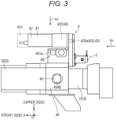
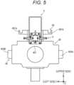
- the trunnion 40 will be described with reference to Figs. 3 to 5 .
- the trunnion 40 has a support hole 401.
- the rod member 31 of the telescopic cylinder 3 is inserted into the support hole 401 in the X direction.
- the trunnion 40 is fixed to a proximal end portion (an end portion on the negative side of the X direction) of the cylinder member 32 of the telescopic cylinder 3. Therefore, the trunnion 40 moves together with the cylinder member 32.
- the trunnion 40 supports the cylinder connecting mechanism 45 and the boom connecting mechanism 46. Furthermore, the trunnion 40 supports the electric motor 41, the brake mechanism 42, and the transmission mechanism 43 to be described below. In this manner, the trunnion 40 unitizes these elements. Such a configuration contributes to size reduction of the pin moving mechanism 4, improvement of productivity, and improvement of system reliability.
- the trunnion 40 holds the right cylinder connecting pin 454A by a right pin support portion (not illustrated) provided on a right wall portion thereof.
- the right cylinder connecting pin 454A is movable in the left-right direction.
- the trunnion 40 holds the left cylinder connecting pin 454B by a left pin support portion (not illustrated) provided on a left wall portion thereof.
- the left cylinder connecting pin 454B is movable in the left-right direction.
- the electric motor 41 is fixed to a vertical transmission mechanism 432 via a decelerator 431. Such an electric motor 41 is covered with a cover 410 for waterproofing and dustproofing. As illustrated in Fig. 3 , the electric motor 41 is provided above the trunnion 40. The decelerator 431 is connected to an output shaft of the electric motor 41 (see Figs. 10A to 10C ).
- the electric motor 41 is connected to, for example, a power supply device (not illustrated) provided on the turning table 12, via a power supply cable. Furthermore, the electric motor 41 is connected to, for example, a control unit (not illustrated) provided on the turning table 12, via a control signal transmission cable.
- the brake mechanism 42 applies a braking force to the electric motor 41.
- the brake mechanism 42 prevents the output shaft of the electric motor 41 from rotating in a stopped state of the electric motor 41. As a result, the state of the pin moving mechanism 4 is maintained in the stopped state of the electric motor 41.
- the brake mechanism 42 operates in a retracted state of the cylinder connecting mechanism 45 or a retracted state of the boom connecting mechanism 46 to be described below to maintain the states of the cylinder connecting mechanism 45 and the boom connecting mechanism 46.
- the state of the brake mechanism 42 is switched by a control unit 530 (see Figs. 10A to 11C ).
- the state of the brake mechanism 42 may be switched on the basis of an operation of an operator.
- the transmission mechanism 43 transmits motive power from the electric motor 41 to the cylinder connecting mechanism 45 and the boom connecting mechanism 46.
- the transmission mechanism 43 includes a decelerator 431 and a vertical transmission mechanism 432.
- the decelerator 431 decelerates the rotation of the electric motor 41 and transmits the decelerated rotation to the vertical transmission mechanism 432.
- the vertical transmission mechanism 432 transmits the rotation of the decelerator 431 to a switch gear 450 ( Figs. 10A to 10C ) to be described below.
- the electric motor 41 is provided above the switch gear 450. Therefore, the vertical transmission mechanism 432 is configured to transmit the rotation of the electric motor 41 to the switch gear 450 provided below the electric motor 41.
- the vertical transmission mechanism 432 includes an upper transmission shaft 432a, a lower transmission shaft 432b, and a transmission gear (not illustrated).
- the upper transmission shaft 432a is provided to be coaxial with the output shaft of the electric motor 41.
- the upper transmission shaft 432a is connected to the decelerator 431.
- the lower transmission shaft 432b corresponds to an example of a rotary member that rotates based on the motive power from the motor, and is provided in parallel with the upper transmission shaft 432a and below the upper transmission shaft 432a.
- the lower transmission shaft 432b is disposed to be coaxial with the switch gear 450 to be described below, and is connected to the switch gear 450.
- the rotary member that rotates based on the motive power from the motor is not limited to the lower transmission shaft 432b.
- the rotary member that rotates based on the motive power from the motor may be any member that rotates based on the motive power from the electric motor 41.
- the transmission gear includes an upper gear (not illustrated) provided on the upper transmission shaft 432a and a lower gear (not illustrated) provided on the lower transmission shaft 432b.
- the upper gear and the lower gear are external gears, and are meshed with each other.
- the rotation of the decelerator 431 is transmitted to the switch gear 450 via the vertical transmission mechanism 432.
- the cylinder connecting mechanism 45 operates based on motive power from the electric motor 41, transition in state between an extended state (see Figs. 9 and 10A ) and a retracted state (see Fig. 10C ).
- the operation in which the cylinder connecting mechanism 45 transitions from the extended state to the retracted state is an operation of removing the cylinder connecting mechanism 45.
- the operation in which the cylinder connecting mechanism 45 transitions from the retracted state to the extended state is an operation of inserting the cylinder connecting mechanism 45.
- the cylinder connecting mechanism 45 includes a switch gear 450, a first rack bar 451, a first gear mechanism 452, a second gear mechanism 453, a pair of cylinder connecting pins 454A and 454B, and a first biasing mechanism 455.
- the switch gear 450 has a teeth portion on a partial portion of an outer peripheral surface thereof.
- the switch gear 450 is externally fitted and fixed to the lower transmission shaft 432b of the transmission mechanism 43, and rotates together with the lower transmission shaft 432b.
- the switch gear 450 selectively transmits motive power from the electric motor 41 to one of the cylinder connecting mechanism 45 and the boom connecting mechanism 46.
- the rotation direction (the direction indicated by arrow A 1 in Fig. 10A ) of the switch gear 450 when the cylinder connecting mechanism 45 transitions from the extended state to the retracted state is a first direction of the rotation direction of the switch gear 450.
- the rotation direction of the switch gear 450 (a direction indicated by arrow A 2 in Fig. 10A ) when the cylinder connecting mechanism 45 transitions from the retracted state to the extended state is a second direction of the rotation direction of the switch gear 450.
- the first rack bar 451 moves in its longitudinal direction (Y direction) as the switch gear 450 moves.
- the first rack bar 451 is located on the most positive side of the Y direction in the extended state of the cylinder connecting mechanism 45.
- the first rack bar 451 is located on the most negative side of the Y direction in the retracted state of the cylinder connecting mechanism 45.
- the first rack bar 451 has a first rack teeth portion on an upper surface thereof.
- the first rack teeth portion meshes with the teeth portion of the switch gear 450 only during the above-described state transition.
- first rack bar 451 has a second rack teeth portion and a third rack teeth portion on a lower surface thereof.
- the second rack teeth portion meshes with the first gear mechanism 452 to be described below.
- the third rack teeth portion meshes with the second gear mechanism 453 to be described below.
- the first gear mechanism 452 includes a plurality of gears (see Fig. 9 ) each of which is an external gear.
- the first gear mechanism 452 meshes with the second rack teeth portion of the first rack bar 451.
- the first gear mechanism 452 rotates as the first rack bar 451 moves.
- the first gear mechanism 452 meshes with a pin-side rack teeth portion of the right cylinder connecting pin 454A to be described below.
- the second gear mechanism 453 includes a plurality of gears (see Fig. 9 ) each of which is an external gear.
- the second gear mechanism 453 meshes with the third rack teeth portion of the first rack bar 451.
- the second gear mechanism 453 rotates as the first rack bar 451 moves.
- the second gear mechanism 453 meshes with a pin-side rack teeth portion of the left cylinder connecting pin 454B to be described below.
- the pair of cylinder connecting pins 454A and 454B have center axes coinciding with each other in the left-right direction, and are coaxial with each other.
- Each of the pair of cylinder connecting pins 454A and 454B corresponds to an example of a first pin.
- the right cylinder connecting pin 454A has a pin-side rack teeth portion on an outer peripheral surface thereof.
- the pin-side rack teeth portion of the right cylinder connecting pin 454A meshes with the first gear mechanism 452.
- the left cylinder connecting pin 454B has a pin-side rack teeth portion on an outer peripheral surface thereof.
- the pin-side rack teeth portion of the left cylinder connecting pin 454B meshes with the second gear mechanism 453.
- the right cylinder connecting pin 454A having the above-described configuration is supported by the right wall portion of the trunnion 40.
- a movement of the right cylinder connecting pin 454A in an axial direction (left-right direction) is guided by the right wall portion of the trunnion 40.
- the left cylinder connecting pin 454B is supported by the left wall portion of the trunnion 40. A movement of the left cylinder connecting pin 454B in the axial direction is guided by the left wall portion.
- the right cylinder connecting pin 454A moves in its axial direction as the first gear mechanism 452 rotates. Specifically, the right cylinder connecting pin 454A moves rightward (outward) when the cylinder connecting mechanism 45 transitions from the retracted state (see Fig. 10C ) to the extended state (see Fig. 10A ). On the other hand, the right cylinder connecting pin 454A moves leftward (inward) when the cylinder connecting mechanism 45 transitions from the extended state (see Fig. 10A ) to the retracted state (see Fig. 10C ).
- the left cylinder connecting pin 454B moves in its axial direction as the second gear mechanism 453 rotates. Specifically, the left cylinder connecting pin 454B moves leftward when the cylinder connecting mechanism 45 transitions from the retracted state (see Fig. 10C ) to the extended state (see Fig. 10A ). On the other hand, the left cylinder connecting pin 454B moves rightward when the cylinder connecting mechanism 45 transitions from the extended state (see Fig. 10A ) to the retracted state (see Fig. 10C ).
- the first biasing mechanism 455 returns the cylinder connecting mechanism 45 to the extended state when the electric motor 41 is in a non-energized state in the retracted state of the cylinder connecting mechanism 45. In other words, when the electric motor 41 is in a non-energized state (stopped state) and the brake mechanism 42 is in a turn-off state in the retracted state of the cylinder connecting mechanism 45, the first biasing mechanism 455 returns the pair of cylinder connecting pins 454A and 454B to reference positions.
- the first biasing mechanism 455 corresponds to an example of a first spring, and includes a pair of coil springs 455a and 455b (see Figs. 10A to 10C ).
- the right coil spring 455a normally biases the right cylinder connecting pin 454A.
- the direction in which the right coil spring 455a biases the cylinder connecting pin 454A coincides with the direction (right side) from the proximal end portion toward the distal end portion of the cylinder connecting pin 454A.
- the left coil spring 455b normally biases the left cylinder connecting pin 454B.
- the direction in which the left coil spring 455b biases the left cylinder connecting pin 454B coincides with the direction (left side) from the proximal end portion toward the distal end portion of the cylinder connecting pin 454B.
- the configuration of the first biasing mechanism 455 as described above contributes to size reduction of the pin moving mechanism 4. Note that the arrangement of the coil springs 455a and 455b is not limited to the arrangement in the present embodiment. The operation of the cylinder connecting mechanism 45 will be described below.
- the boom connecting mechanism 46 transitions between an extended state (see Fig. 11A ) and a retracted state (see Fig. 11C ) based on a rotation of the electric motor 41.
- the operation in which the boom connecting mechanism 46 transitions from the extended state to the retracted state is an operation of removing the boom connecting mechanism 46.
- the operation in which the boom connecting mechanism 46 transitions from the retracted state to the extended state is an operation of inserting the boom connecting mechanism 46.
- the boom connecting mechanism 46 can take either an engaged state or a disengaged state with respect to a boom connecting pin (e.g., the pair of boom connecting pins 144a).
- the boom connecting mechanism 46 disengages the boom connecting pin from the boom by transitioning from the extended state to the retracted state while being engaged with the boom connecting pin.
- the boom connecting pin corresponds to an example of a second pin.
- the boom connecting mechanism 46 engages the boom with the boom connecting pin by transitioning from the retracted state to the extended state while being engaged with the boom connecting pin.
- the boom connecting mechanism 46 includes a switch gear 450, a pair of second rack bars 461a and 461b, a synchronization gear 462, and a second biasing mechanism 463.
- the switch gear 450 is a gear shared with the cylinder connecting mechanism 45.
- the pair of second rack bars 461a and 461b are, for example, shaft members each being long in the left-right direction, and are disposed in parallel with each other while being separated from each other in the front-rear direction.
- Each of the pair of second rack bars 461a and 461b is disposed above the first rack bar 451 of the cylinder connecting mechanism 45.
- the pair of second rack bars 461a and 461b have synchronization rack teeth portions on their respective surfaces facing each other. Each of the synchronization rack teeth portions meshes with the synchronization gear 462 (see Figs. 11A to 11C ).
- the synchronization gear 462 rotates, the second rack bar 461a on one side (front side) and the second rack bar 461b on the other side (rear side) move in opposite directions in the left-right direction.
- the pair of second rack bars 461a and 461b have locking claw portions 461g and 461h (see Fig. 9 ) at their respective distal end portions.
- the locking claw portions 461g and 461h are engaged with pin-side receiving portions 144c (see Fig. 9 ) provided in the boom connecting pins (e.g., the boom connecting pins 144a and 144b) when the boom connecting pins are moved.
- the second rack bar 461a has a driving rack teeth portion 461c (see Fig. 9 ) on a surface facing the switch gear 450.
- the driving rack teeth portion 461c mesh with the teeth portion of the switch gear 450 when the switch gear 450 rotates by a predetermined amount in the second direction (a direction indicated by arrow A 2 in Fig. 9 ).
- the second biasing mechanism 463 returns the boom connecting mechanism 46 to the extended state when the electric motor 41 is in the non-energized state and the brake mechanism 42 is in the turn-off state in the retracted state of the boom connecting mechanism 46.
- the second biasing mechanism 463 biases the pair of second rack bars 461a and 461b in directions away from each other.
- the second biasing mechanism 463 includes a pair of coil springs 463a and 463b (see Figs. 11A to 11C ).
- the pair of coil springs 463a and 463b bias proximal end portions of the pair of second rack bars 461a and 461b toward distal ends of the pair of second rack bars 461a and 461b, respectively.
- the operation of the cylinder connecting mechanism 45 is an operation when the cylinder connecting mechanism 45 transitions from the extended state to the retracted state based on motive power from the electric motor 41, or an operation when the cylinder connecting mechanism 45 transitions from the retracted state to the extended state based on biasing force on the first biasing mechanism 455.
- Fig. 10A is a schematic view illustrating the extended state of the cylinder connecting mechanism 45 and the engaged state between the pair of cylinder connecting pins 454A and 454B and the pair of cylinder pin receiving portions 141a of the distal boom 141.
- Fig. 10B is a schematic view illustrating a state in the middle of transition of the cylinder connecting mechanism 45 from the extended state to the retracted state.
- Fig. 10C is a schematic view illustrating the retracted state of the cylinder connecting mechanism 45 and the disengaged state between the pair of cylinder connecting pins 454A and 454B and the pair of cylinder pin receiving portions 141a of the distal boom 141.
- the extended state of the cylinder connecting mechanism 45 illustrated in Fig. 10A corresponds to the state of the cylinder connecting mechanism 45 in Figs. 2A to 2D .
- the state of the cylinder connecting mechanism 45 illustrated in Fig. 10B corresponds to a state in the middle of transition from the state of the cylinder connecting mechanism 45 illustrated in Fig. 2D to the state of the cylinder connecting mechanism 45 illustrated in Fig. 2E .
- the retracted state of the cylinder connecting mechanism 45 illustrated in Fig. 10C corresponds to the state of the cylinder connecting mechanism 45 illustrated in Fig. 2E .
- control unit 530 drives the electric motor 41.
- the motive power from the electric motor 41 is transmitted to the pair of cylinder connecting pins 454A and 454B through a first transmission path and a second transmission path to be described below.
- the control unit 530 may have a configuration in which a CPU, a ROM, a RAM, an HDD, and the like are substantially connected to each other by a bus, or a configuration including a one-chip LSI or the like.
- the first transmission path is a path through which the motive power from the electric motor 41 is transmitted in the following order.
- switch gear 450 ⁇ first rack bar 451 ⁇ first gear mechanism 452 ⁇ right cylinder connecting pin 454A
- the second transmission path is a path through which the motive power from the electric motor 41 is transmitted in the following order.
- switch gear 450 ⁇ first rack bar 451 ⁇ second gear mechanism 453 ⁇ left cylinder connecting pin 454B
- the switch gear 450 rotates in the first direction (the direction indicated by arrow A 1 in Fig. 10A ) based on the motive power from the electric motor 41.
- the lower transmission shaft 432b of the vertical transmission mechanism 432 rotates in the first direction together with the switch gear 450.
- the first rack bar 451 moves rightward in accordance with the rotation.
- the right cylinder connecting pin 454A moves leftward via the first gear mechanism 452.
- the left cylinder connecting pin 454B moves rightward via the second gear mechanism 453.
- the position information detection device 5 detects that the pair of cylinder connecting pins 454A and 454B are disengaged from the pair of cylinder pin receiving portions 141a of the distal boom 141 and moved to predetermined positions (e.g., the positions illustrated in Fig. 10C ). Then, based on the detection result, the control unit 530 (see Figs. 10A to 11C ) turns off the electric motor 41 while turning on the brake mechanism 42 to stop the operation of the cylinder connecting mechanism 45.
- the transition of the cylinder connecting mechanism 45 from the retracted state to the extended state is automatically performed based on the biasing force of the first biasing mechanism 455 when the brake mechanism 42 is turned off in the non-energized state of the electric motor 41.
- Fig. 11A is a schematic view illustrating the extended state of the boom connecting mechanism 46 and the engaged state between the pair of boom connecting pins 144a and the pair of first boom pin receiving portions 142b of the intermediate boom 142.
- Fig. 11B is a schematic view illustrating a state in the middle of state transition of the boom connecting mechanism 46 from the extended state to the retracted state.
- Fig. 11C is a schematic view illustrating the retracted state of the boom connecting mechanism 46 and the disengaged state between the pair of boom connecting pins 144a and the pair of first boom pin receiving portions 142b of the intermediate boom 142.
- the extended state of the boom connecting mechanism 46 illustrated in Fig. 11A corresponds to the state of the boom connecting mechanism 46 in Fig. 2A .
- the state of the boom connecting mechanism 46 illustrated in Fig. 11B corresponds to a state in the middle of transition from the state of the boom connecting mechanism 46 illustrated in Fig. 2A to the state of the boom connecting mechanism 46 illustrated in Fig. 2B .
- the retracted state of the boom connecting mechanism 46 illustrated in Fig. 11C corresponds to the state of the boom connecting mechanism 46 illustrated in Fig. 2B .
- the boom connecting mechanism 46 transitions between the extended state and the retracted state based on motive power from the electric motor 41.
- the position of the switch gear 450 illustrated in Fig. 11A is defined as a reference position of the switch gear 450.
- the control unit 530 drives the electric motor 41 in a direction opposite to a direction in which the cylinder connecting mechanism 45 is operated.
- the motive power from the electric motor 41 is transmitted through the following path. (Transmission path) switch gear 450 ⁇ one second rack bar 461a ⁇ synchronization gear 462 ⁇ the other second rack bar 461b
- the switch gear 450 rotates in the second direction (the direction indicated by arrow A 2 in Fig. 11A ) of the rotation direction of the switch gear 450 based on the motive power from the electric motor 41.
- the lower transmission shaft 432b of the vertical transmission mechanism 432 rotates in the second direction together with the switch gear 450.
- one second rack bar 461a moves rightward in accordance with the rotation.
- the synchronization gear 462 rotates in accordance with the rightward movement of one second rack bar 461a. Then, the other second rack bar 461b moves leftward in accordance with the rotation of the synchronization gear 462.
- the position information detection device 5 detects that the pair of boom connecting pins 144a are disengaged from the pair of first boom pin receiving portions 142b of the intermediate boom 142 and moved to predetermined positions (e.g., the positions illustrated in Fig. 11C ). Then, based on the detection result, the control unit 530 turns off the electric motor 41 while turning on the brake mechanism 42 to stop the operation of the boom connecting mechanism 46.
- the position information detection device 5 detects that the pair of boom connecting pins 144a are engaged with the pair of first boom pin receiving portions 142b of the intermediate boom 142 and moved to predetermined positions (e.g., the positions illustrated in Fig. 11A ). The detection result is used to control the next operation of the actuator 2.
- the position information detection device 5 detects information on the positions of the pair of cylinder connecting pins 454A and 454B and the pair of boom connecting pins 144a and 144b.
- the position information detection device 5 includes a support 50, a first detection device 51, a second detection device 52, and a cover member 54.
- the first detection device 51 and the second detection device 52 are supported on the trunnion 40 by a support 50.
- the first detection device 51 and the second detection device 52 detect information on the positions of the pair of cylinder connecting pins 454A and 454B and the pair of boom connecting pins 144a and 144b by different detection methods.
- the first detection device 51 and the second detection device 52 detects the information on the positions of the pair of cylinder connecting pins 454A and 454B and the pair of boom connecting pins 144a and 144b. Then, for example, when the control unit 530 (see Figs. 10A to 11C ) detects a failure of the one detection device, the other one of the first detection device 51 and the second detection device 52 detects information on the positions of the pair of cylinder connecting pins 454A and 454B and the pair of boom connecting pins 144a and 144b.
- the one detection device is the second detection device 52, and the other detection device is the first detection device 51.
- the one detection device may be the first detection device 51, and the other detection device may be the second detection device 52.
- the first detection device 51 and the second detection device 52 may detect the information on the positions of the pair of cylinder connecting pins 454A and 454B and the pair of boom connecting pins 144a and 144b.
- each of the first detection device 51 and the second detection device 52 cannot detect its failure by itself. Therefore, when there is a contradiction (e.g., a deviation of a predetermined value or more) between a detection value of the first detection device 51 and a detection value of the second detection device 52, the control unit 530 may determine that a failure has occurred in at least one of the first detection device 51 and the second detection device 52.
- a contradiction e.g., a deviation of a predetermined value or more
- control unit 530 may determine a failure of a detection device based on the detection values of the first detection device 51 and the second detection device 52 while detecting information on the positions of the pair of cylinder connecting pins 454A and 454B and the pair of boom connecting pins 144a and 144b based on the detection value of the second detection device 52.
- control unit 530 does not detect information on the positions of the pair of cylinder connecting pins 454A and 454B and the pair of boom connecting pins 144a and 144b based on the detection value of the first detection device 51.
- the control unit 530 may detect the information on the positions of the pair of cylinder connecting pins 454A and 454B and the pair of boom connecting pins 144a and 144b based on the detection value of the first detection device 51.
- the support 50 is a member that supports the first detection device 51 and the second detection device 52 on the trunnion 40.
- the support 50 is fixed to the trunnion 40. Specifically, the support 50 is fixed to a rear side surface (a side surface on the negative side of the X direction) of the trunnion 40.
- the support 50 includes a right side plate 501, a left side plate 502, a rear side plate 503, a right side fixing plate 504, and a left side fixing plate 505.
- the right side plate 501 has a shape like a plate parallel to the X-Z plane.
- the left side plate 502 has a shape like a plate parallel to the X-Z plane.
- the right side plate 501 and the left side plate 502 are separated from each other in the left-right direction (Y direction) and face each other.
- Each of the right side plate 501 and the left side plate 502 corresponds to an example of a first plate portion.
- the rear side plate 503 corresponds to an example of a second plate portion, and has a shape like a plate parallel to the Y-Z plane.
- the rear side plate 503 connects a rear end portion (an end portion on the negative side of the X direction) of the right side plate 501 and a rear end portion (an end portion on the negative side of the X direction) of the left side plate 502 in the left-right direction. That is, the support 50 is a U-shaped and plate-shaped member that is open in the up-down direction and open forward.
- a space surrounded by the right side plate 501, the left side plate 502, and the rear side plate 503 of the support 50 is an accommodation space 506.
- the accommodation space 506 may be regarded as a space defined by the support 50.
- the right side fixing plate 504 has a shape like a plate parallel to the Y-Z plane.
- the right side fixing plate 504 is fixed to a front end portion of the right side plate 501.
- the left side fixing plate 505 has a shape like a plate parallel to the Y-Z plane.
- the left side fixing plate 505 is fixed to a front end portion of the left side plate 502.
- the front end portions of the support 50 (the front end portions of the right side plate and the left side plate) are fixed to a rear side surface of the trunnion 40 via the right side fixing plate 504 and the left side fixing plate 505.
- each of the right side fixing plate 504 and the left side fixing plate 505 is positioned with respect to the trunnion 40 by a positioning pin 507 inserted into a fixed portion 400 on the trunnion side.
- Such a configuration contributes to improvement of assembling work efficiency when the support 50 is assembled to the trunnion 40.
- the lower transmission shaft 432b is disposed between the right side plate 501 and the left side plate 502 of the support 50. That is, the lower transmission shaft 432b is disposed in the accommodation space 506.
- the right side plate 501 and the left side plate 502 are parallel to the lower transmission shaft 432b.
- the first detection device 51 includes a first detection object 510, a second detection object 511, a first sensor 512, a second sensor 513, and a third sensor 514.
- the first detection device 51 detects information on the positions of the pair of cylinder connecting pins 454A and 454B and the pair of boom connecting pins 144a and 144b based on a combination of outputs (detection values) of the first sensor 512, the second sensor 513, and the third sensor 514.
- the first detection object 510 is fixed to the lower transmission shaft 432b in a state where the lower transmission shaft 432b is inserted into a center hole thereof. That is, the first detection object 510 is disposed in the accommodation space 506.
- the first detection object 510 rotates together with the lower transmission shaft 432b.
- the first detection object 510 has a first cylindrical surface 510a and a first flat surface 510b on an outer peripheral surface thereof.
- the first cylindrical surface 510a corresponds to an example of a first detection surface of the first detection object.
- the first cylindrical surface 510a is a cylindrical surface having a predetermined outer diameter and provided on a partial portion (also referred to as a first portion) of the outer peripheral surface of the first detection object 510.
- the first flat surface 510b corresponds to an example of a second detection surface of the first detection object.
- the first flat surface 510b is a flat surface provided on the other portion (also referred to as a second portion) of the outer peripheral surface of the first detection object 510.
- the shapes of the first detection surface of the first detection object and the second detection surface of the first detection object are not limited to the shapes in the present embodiment. It is only required that the shapes of the first detection surface of the first detection object and the second detection surface of the first detection object are shapes that can be distinguished from each other (that is, different shapes).
- the first cylindrical surface 510a is disposed in a lower half portion, and the first flat surface 510b is disposed in an upper half portion.
- the neutral state of the first detection object 510 corresponds to the inserted state of the pair of cylinder connecting pins 454A and 454B and the boom connecting pins 144a (see Figs. 2A to 2E ).
- the second detection object 511 is fixed to the lower transmission shaft 432b in a state where the lower transmission shaft 432b is inserted into a center hole thereof. That is, the second detection object 511 is disposed in the accommodation space 506. The second detection object 511 rotates together with the lower transmission shaft 432b. The second detection object 511 is disposed in front of the first detection object 510.
- the second detection object 511 has a second cylindrical surface 511a and a second flat surface 511b on an outer peripheral surface thereof.
- the second cylindrical surface 511a corresponds to an example of a first detection surface of the second detection object.
- the second cylindrical surface 511a is a cylindrical surface having a predetermined outer diameter and provided on a partial portion (also referred to as a first portion) of the outer peripheral surface of the second detection object 511.
- the second flat surface 511b corresponds to an example of a second detection surface of the second detection object.
- the second flat surface 511b is a flat surface provided on the other portion (also referred to as a second portion) of the outer peripheral surface of the second detection object 511.
- the shapes of the first detection surface of the second detection object and the second detection surface of the second detection object are not limited to the shapes in the present embodiment. It is only required that the shapes of the first detection surface of the second detection object and the second detection surface of the second detection object are shapes that can be distinguished from each other (that is, different shapes).
- the second cylindrical surface 511a is disposed in a left half portion, and the second flat surface 511b is disposed in a right half portion.
- the neutral state of the second detection object 511 corresponds to the inserted state of the pair of cylinder connecting pins 454A and 454B and the boom connecting pins 144a (see Figs. 2A to 2E ).
- the neutral state of the second detection object 511 corresponds to the extended state of the cylinder connecting mechanism 45 and the extended state of the boom connecting mechanism 46 as illustrated in Figs. 10A and 11A .
- Each of the first sensor 512, the second sensor 513, and the third sensor 514 corresponds to an example of a first detection unit, and is a non-contact proximity sensor.
- Each of the first sensor 512, the second sensor 513, and the third sensor 514 is supported by the support 50.
- the first sensor 512 is supported by the right side plate 501 of the support 50. A distal end portion of the first sensor 512 faces the outer peripheral surface of the first detection object 510 in the left-right direction.
- the first sensor 512 outputs an electric signal corresponding to a distance from the outer peripheral surface of the first detection object 510.
- the output of the first sensor 512 is turned on while facing the first cylindrical surface 510a of the first detection object 510.
- the output of the first sensor 512 is turned off while facing the first flat surface 510b of the first detection object 510.
- the second sensor 513 is supported by the left side plate 502 of the support 50. A distal end portion of the second sensor 513 faces the outer peripheral surface of the first detection object 510 in the left-right direction.
- the first sensor 512 and the second sensor 513 face each other in the left-right direction.
- the second sensor 513 outputs an electric signal corresponding to a distance from the outer peripheral surface of the first detection object 510.
- the output of the second sensor 513 is turned on while facing the first cylindrical surface 510a of the first detection object 510.
- the output of the second sensor 513 is turned off while facing the first flat surface 510b of the first detection object 510.
- the third sensor 514 is supported by the right side plate 501 of the support 50.
- the third sensor 514 is disposed in front of the first sensor 512 on the right side plate 501 of the support 50.
- a distal end portion of the third sensor 514 faces the outer peripheral surface of the second detection object 511 in the left-right direction.
- the third sensor 514 outputs an electric signal corresponding to a distance from the outer peripheral surface of the second detection object 511.
- the third sensor 514 may be supported by the left side plate 502 of the support 50.
- the position of the third sensor 514 is not limited to the illustrated position.
- the output of the third sensor 514 is turned on while facing the second cylindrical surface 511a of the second detection object 511.
- the output of the third sensor 514 is turned off while facing the second flat surface 511b of the second detection object 511.
- the second detection device 52 is a non-contact potentiometer, and includes a detection object 520 and a sensor 521.
- the detection object 520 is a magnet, and is fixed to the lower transmission shaft 432b in a state where a rear end portion of the lower transmission shaft 432b is inserted into a center hole thereof. Accordingly, the detection object 520 rotates together with the lower transmission shaft 432b.
- the detection object 520 is disposed behind the first detection object 510 of the first detection device 51.
- the sensor 521 corresponds to an example of a second detection unit, has a Hall element, and is supported by the rear side plate 503 of the support 50.
- the first sensor 512, the second sensor 513, and the third sensor 514 of the first detection device 51, and the sensor 521 of the second detection device 52 are supported by the support 50.
- the support 50 unitizes the first sensor 512, the second sensor 513, and the third sensor 514 of the first detection device 51, and the sensor 521 of the second detection device 52. Therefore, by removing the support 50 from the trunnion 40, the sensors 512, 513, 514, and 521 can be collectively removed from the trunnion 40.
- Such a configuration contributes to improvement of assembly work efficiency and improvement of maintenance work efficiency.
- the detection surfaces of the sensors 512, 513, 514, and 521 are disposed in the accommodation space 506 surrounded by the support 50. Such a configuration is capable of suppressing damage to the detection surfaces of the sensors 512, 513, 514, and 521.
- the sensor 521 faces the detection object 520 in the front-rear direction.
- the sensor 521 outputs a voltage corresponding to a phase of the detection object 520. That is, the sensor 521 outputs a voltage corresponding to a rotation angle of the lower transmission shaft 432b to which the detection object 520 is fixed.
- a method (detection method) in which the first detection device 51 detects information regarding a position is different from a method (detection method) in which the second detection device 52 detects information regarding a position. That is, the pin moving mechanism 4 according to the present embodiment includes two detection mechanisms having different detection methods for detecting information on the positions of the pair of cylinder connecting pins 454A and 454B and the pair of boom connecting pins 144a and 144b.
- the second detection device may be a contact potentiometer or an encoder.
- the cover member 54 is, for example, a plate member having a rectangular shape and parallel to the X-Y plane. As illustrated in Figs. 7 and 8 , the cover member 54 covers an upper opening of the support 50 from above. In Fig. 6 , the cover member 54 is omitted.
- the cover member 54 is fixed to an upper end portion of the support 50 or the trunnion 40. Such a cover member 54 suppresses intrusion of foreign matter into the accommodation space 506 from the upper opening of the support 50. Furthermore, as illustrated in Figs. 7 and 8 , a lower opening of the support 50 faces a surface of the telescopic cylinder 3 (specifically, the rod member 31) with a predetermined distance therebetween. Such a configuration suppresses intrusion of foreign matter into the accommodation space 506 from the lower opening of the support 50.
- the reliability of the detection results of the first detection device 51 and the second detection device 52 can be secured.
- the lower opening of the accommodation space 506 faces the surface of the telescopic cylinder 3, even if the first detection object 510 and the second detection object 511 of the first detection device 51 or the detection object 520 of the second detection device 52 fall off from the lower transmission shaft 432b, it is possible to suppress falling of each of the detection objects 510, 511, and 520 downward.
- the second detection device 52 detects information on the positions of the pair of cylinder connecting pins 454A and 454B and the boom connecting pins 144a.
- the first detection device 51 detects information on the positions of the pair of cylinder connecting pins 454A and 454B and the boom connecting pins 144a.
- the first detection device 51 and the second detection device 52 may detect information on the positions of the pair of cylinder connecting pins 454A and 454B and the boom connecting pins 144a from the normal time.
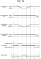
- Fig. 12 is a timing chart at the time of the operation of extending the distal boom 141 in the telescopic boom 14.
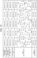
- Fig. 13 is a view illustrating a relationship between the states of the pair of cylinder connecting pins 454A and 454B and the boom connecting pins 144a and the states of the first detection device 51 and the second detection device 52.
- control unit (not illustrated) controls the electric motor 41 to be switched on/off and controls the brake mechanism 42 to be switched on/off based on the output of the position information detection device 5.
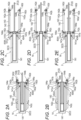
- Fig. 2A illustrates a retracted state of the telescopic boom 14.
- the distal boom 141 is connected to the intermediate boom 142 via the boom connecting pins 144a. Therefore, the distal boom 141 cannot be displaced with respect to the intermediate boom 142 in the longitudinal direction (the left-right direction in Figs. 2A to 2E ).
- the first detection device 51 and the second detection device 52 of the position information detection device 5 are in the neutral state as illustrated in Fig. 13 .
- the first sensor 512 and the second sensor 513 face the first cylindrical surface 510a of the first detection object 510. Therefore, the outputs of the first sensor 512 and the second sensor 513 are turned on.
- the third sensor 514 faces the second flat surface 511b of the second detection object 511. Therefore, the output of the third sensor 514 is turned off.
- the first detection device 51 detects that the pair of cylinder connecting pins 454A and 454B are in the inserted state and the boom connecting pins 144a are in the inserted state.
- the switch gear 450 is located at the reference position illustrated in Figs. 10A and 11A .
- the rotation angle of the detection object 520 is 0 degrees.
- the sensor 521 is configured to, in the neutral state of the second detection device 52, output a predetermined voltage (hereinafter referred to as a neutral voltage) corresponding to the neutral state.
- a neutral voltage a predetermined voltage
- the switch gear 450 is located at the reference position illustrated in Figs. 10A and 11A .
- the second detection device 52 detects that the pair of cylinder connecting pins 454A and 454B are in the inserted state and the boom connecting pins 144a are in the inserted state.
- the electric motor 41 is rotated normally (rotated in the direction indicated by arrow A 2 in Fig. 11A ), and the pair of boom connecting pins 144a are displaced in such a direction to be disengaged from the pair of first boom pin receiving portions 142b of the intermediate boom 142 by the boom connecting mechanism 46 of the actuator 2.
- the boom connecting mechanism 46 transitions from the extended state to the retracted state.
- the first sensor 512 faces the first cylindrical surface 510a of the first detection object 510. Therefore, the output of the first sensor 512 is turned on.
- the second sensor 513 faces the first flat surface 510b of the first detection object 510. Therefore, the output of the second sensor 513 is turned off.
- the third sensor 514 faces the second flat surface 511b of the second detection object 511. Therefore, the output of the third sensor 514 is turned off.
- the first detection device 51 detects that the boom connecting pins 144a transition from the inserted state to the removed state.
- the first detection device 51 When the boom connecting pins 144a are in the removed state, the first detection device 51 is in the second state. Conversely, when the first detection device 51 is in the second state, the boom connecting pins 144a are in the removed state (the state illustrated in Fig. 2B ) .
- the first sensor 512 faces the first cylindrical surface 510a of the first detection object 510. Therefore, the output of the first sensor 512 is turned on.
- the second sensor 513 faces the first flat surface 510b of the first detection object 510. Therefore, the output of the second sensor 513 is turned off.
- the third sensor 514 faces the second cylindrical surface 511a of the second detection object 511. Therefore, the output of the third sensor 514 is turned on.
- the first detection device 51 detects that the boom connecting pins 144a are in the removed state.
- the output of the sensor 521 changes depending on the phase of the detection object 520.
- the sensor 521 is configured to output a predetermined voltage (hereinafter referred to as a second voltage) corresponding to the second state. Therefore, when the state of the second detection device 52 transitions from the neutral state to the second state, the output of the sensor 521 changes from the neutral voltage to the second voltage.
- the second detection device 52 detects that the boom connecting pins 144a transition from the inserted state to the removed state.
- the second detection device 52 When the boom connecting pins 144a are in the removed state, the second detection device 52 is in the second state. Conversely, when the second detection device 52 is in the second state, the boom connecting pins 144a are in the removed state. In the second state of the second detection device 52, the output of the sensor 521 is the second voltage. When the output of the sensor 521 is the second voltage, the second detection device 52 detects that the boom connecting pins 144a are in the removed state.
- the control unit turns off the electric motor 41 while turning on the brake mechanism 42 to stop the operation of the boom connecting mechanism 46.
- the timing at which the electric motor 41 is turned off and the timing at which the brake mechanism 42 is turned on are appropriately controlled by the control unit. For example, although not illustrated, the electric motor 41 is turned off after the brake mechanism 42 is turned on.
- pressurized oil is supplied to a hydraulic chamber on the extension side in the telescopic cylinder 3 of the actuator 2. Then, the cylinder member 32 is displaced in the extension direction (the left side in Figs. 2A to 2E ).
- the brake mechanism 42 is released in the state illustrated in Fig. 2C .
- the boom connecting mechanism 46 displaces the pair of boom connecting pins 144a in such a direction as to engage with the pair of second boom pin receiving portions 142c of the intermediate boom 142.
- the state of the boom connecting mechanism 46 transitions (that is, automatically returns) from the retracted state to the extended state.
- the first sensor 512 faces the first cylindrical surface 510a of the first detection object 510. Therefore, the output of the first sensor 512 is turned on.
- the second sensor 513 faces the first flat surface 510b of the first detection object 510. Therefore, the output of the second sensor 513 is turned off.
- the third sensor 514 faces the second flat surface 511b of the second detection object 511. Therefore, the output of the third sensor 514 is turned off.
- the first detection device 51 When the boom connecting pin 144a is in the inserted state, the first detection device 51 is in the neutral state. Conversely, when the first detection device 51 is in the neutral state, the boom connecting pins 144a are in the inserted state (the state illustrated in Fig. 2D ).
- the states of the first sensor 512, the second sensor 513, and the third sensor 514 in the neutral state of the first detection device 51 are as described above.
- the first detection device 51 detects that the boom connecting pins 144a are in the neutral state.
- the output of the sensor 521 changes from the second voltage to the neutral voltage according to the phase of the detection object 520.
- the second detection device 52 detects that the boom connecting pins 144a transition from the removed state to the inserted state.
- the second detection device 52 When the boom connecting pins 144a are in the inserted state, the second detection device 52 is in the neutral state. In the neutral state of the second detection device 52, the output of the sensor 521 is the neutral voltage. When the output of the sensor 521 is the neutral voltage, the second detection device 52 detects that the boom connecting pins 144a are in the inserted state.
- the electric motor 41 is rotated reversely (rotated in the direction indicated by arrow A 1 in Fig. 10A ), and the pair of cylinder connecting pins 454A and 454B are displaced in such a direction to be disengaged from the pair of cylinder pin receiving portions 141a of the distal boom 141 by the cylinder connecting mechanism 45.
- the cylinder connecting mechanism 45 transitions from the extended state to the retracted state.
- the first detection device 51 and the second detection device 52 of the position information detection device 5 transition from the neutral state to the first state in accordance with the rotation of the lower transmission shaft 432b as illustrated in Fig. 13 .
- the first sensor 512 faces the first flat surface 510b of the first detection object 510. Therefore, the output of the first sensor 512 is turned off.
- the second sensor 513 faces the first cylindrical surface 510a of the first detection object 510. Therefore, the output of the second sensor 513 is turned on.
- the third sensor 514 faces the second flat surface 511b of the second detection object 511. Therefore, the output of the third sensor 514 is turned off.
- the first detection device 51 detects that the pair of cylinder connecting pins 454A and 454B transition from the inserted state to the removed state.
- the first detection device 51 When the pair of cylinder connecting pins 454A and 454B are in the removed state, the first detection device 51 is in the first state. Conversely, when the first detection device 51 is in the first state, the pair of cylinder connecting pins 454A and 454B are in the removed state (state illustrated in Fig. 2E ).
- the first sensor 512 faces the first flat surface 510b of the first detection object 510. Therefore, the output of the first sensor 512 is turned off.
- the second sensor 513 faces the first cylindrical surface 510a of the first detection object 510. Therefore, the output of the second sensor 513 is turned on.
- the third sensor 514 faces the second cylindrical surface 511a of the second detection object 511. Therefore, the output of the third sensor 514 is turned on.
- the first detection device 51 detects that the pair of cylinder connecting pins 454A and 454B are in the removed state.
- the output of the sensor 521 changes depending on the phase of the detection object 520.
- the sensor 521 is configured to output a predetermined voltage (hereinafter referred to as a first voltage) corresponding to the first state.
- the output of the sensor 521 changes from the neutral voltage to the first voltage.
- the second detection device 52 detects that the pair of cylinder connecting pins 454A and 454B transitions from the inserted state to the removed state.
- the second detection device 52 When the pair of cylinder connecting pins 454A and 454B are in the removed state, the second detection device 52 is in the first state. In the first state of the second detection device 52, the output of the sensor 521 is the first voltage. When the output of the sensor 521 is the first voltage, the second detection device 52 detects that the pair of cylinder connecting pins 454A and 454B are in the removed state.
- the positions of the pair of cylinder connecting pins 454A and 454B and the boom connecting pins 144a and 144b are detected by the above-described position information detection device 5. Therefore, the telescoping operation of the telescopic boom 14 can be accurately controlled.
- the first detection device 51 and the second detection device 52 which are different in detection method, are included in the position information detection device 5. Then, the second detection device 52 detects information on positions at a normal time, and, the first detection device 51 detects information on positions in a case where the second detection device 52 fails. Therefore, even in a case where any one of the first detection device 51 and the second detection device 52 fails, the positions of the pair of cylinder connecting pins 454A and 454B and the boom connecting pins 144a and 144b can be detected.
- the control unit 530 can determine a failure of a detection device based on detection values of the first detection device 51 and the second detection device 52 while detecting information on the positions of the pair of cylinder connecting pins 454A and 454B and the pair of boom connecting pins 144a and 144b based on the detection value of the second detection device 52. As a result, the control unit 530 can quickly detect that a failure has occurred in at least one of the first detection device 51 and the second detection device 52.
- the first detection device 51 and the second detection device 52 are different in detection method, it is possible to suppress both detection devices from being simultaneously affected by noise. If the first detection device 51 and the second detection device 52 are identical in detection method, there is a possibility that the first detection device 51 and the second detection device 52 are simultaneously affected by noise. On the other hand, in the present embodiment, since the detection method of the first detection device 51 is different from the detection method of the second detection device 52, even in a case where one detection device is affected by noise, the other detection device is less likely to be simultaneously affected by the same.
- the present invention can be applied not only to a crane but also to various work machines (e.g., a high-place work vehicle) each including a telescopic boom.
- work machines e.g., a high-place work vehicle
Landscapes
- Engineering & Computer Science (AREA)
- Mechanical Engineering (AREA)
- Jib Cranes (AREA)
- Mining & Mineral Resources (AREA)
- Civil Engineering (AREA)
- General Engineering & Computer Science (AREA)
- Structural Engineering (AREA)
Abstract
Description
- The present invention relates to a work machine including a telescopic boom.
- A mobile crane including a telescopic boom having a plurality of booms and a hydraulic actuator for extending the telescopic boom is disclosed (see Patent Literature 1).
- The adjacent booms are connected to each other by a boom connecting pin. The boom (hereinafter referred to as a movable boom) of which the connection by the boom connecting pin is released is movable with respect to another boom.
- The actuator includes a rod member and a cylinder member. The cylinder member is releasably coupled to the movable boom by a cylinder connecting pin. When the cylinder member is displaced in an extension/retraction direction while being connected to the movable boom, the movable boom moves together with the cylinder member. Then, the telescopic boom extends and retracts.
- Patent Literature 1:
JP 2012-96928 A - In the crane as described above, a technique for detecting the positions of the boom connecting pin and the cylinder connecting pin is required in order to accurately control a telescoping operation of the telescopic boom.
- An object of the present invention is to provide a work machine capable of accurately controlling a telescoping operation of a telescopic boom.
- According to an aspect of the present invention, a work machine includes:
- a plurality of booms that are extended and retracted by motive power from an actuator;
- a first pin that is moved by a first spring to connect the boom and the actuator to each other and is moved by motive power from a motor to release a connection of the boom and the actuator;
- a second pin that is moved by a second spring to connect adjacent booms of the booms and is moved by motive power from the motor to release a connection of the adjacent booms; and
- a first detection device and a second detection device that detect positions of the first pin and the second pin on the basis of a rotation of a rotary member that is rotated by motive power from the motor.
- According to the present invention, it is possible to provide a work machine capable of accurately controlling a telescoping operation of a telescopic boom.
-
-
Fig. 1 is a schematic view of a mobile crane according to an embodiment. -
Figs. 2A to 2E are schematic views for explaining a structure and a telescoping operation of a telescopic boom. -
Fig. 3 is a side view of a pin moving module. -
Fig. 4 is a view of the pin moving module as viewed from arrow Aa inFig. 3 . -
Fig. 5 is a view of the pin moving module as viewed from arrow Ab inFig. 3 . -
Fig. 6 is a view of a detection device as viewed from arrow Aa inFig. 3 . -
Fig. 7 is a cross-sectional view taken along line X1-X1 ofFig. 6 for explaining a first detection device. -
Fig. 8 is a cross-sectional view taken along line X2-X2 ofFig. 6 for explaining the first detection device. -
Fig. 9 is a view illustrating the pin moving module in which a boom connecting mechanism is in an extended state and a cylinder connecting mechanism is in an extended state. -
Fig. 10A is a schematic view for explaining an operation of the cylinder connecting mechanism. -
Fig. 10B is a schematic view for explaining an operation of the cylinder connecting mechanism. -
Fig. 10C is a schematic view for explaining an operation of the cylinder connecting mechanism. -
Fig. 11A is a schematic view for explaining an operation of the boom connecting mechanism. -
Fig. 11B is a schematic view for explaining an operation of the boom connecting mechanism. -
Fig. 11C is a schematic view for explaining an operation of the boom connecting mechanism. -
Fig. 12 is a timing chart for explaining an operation of the pin moving module. -
Fig. 13 is a table for explaining a detection operation of a position information detection device. - Hereinafter, an example of an embodiment of the present invention will be described in detail with reference to the drawings. Note that the present invention is not limited to the embodiment described below.
- An outline of a mobile crane 1 according to the present embodiment will be described with reference to
Fig. 1 andFigs. 2A to 2E . - The mobile crane is, for example, a rough terrain crane, an all-terrain crane, a truck crane, or a truck loader crane. However, the work machine is not limited to the mobile crane, and may be various work machines (e.g., a high-place work vehicle) including a telescopic boom.
- The mobile crane 1 includes a
telescopic boom 14 and anactuator 2. Thetelescopic boom 14 includes a plurality of booms telescopically combined together. Adjacent booms are connected to each other by boom connecting pins (boom connecting pins - The
actuator 2 moves thetelescopic boom 14 in an extension/retraction direction when extending/retracting thetelescopic boom 14. At this time, theactuator 2 is connected to a boom to be moved viacylinder connecting pins - In the telescoping operation of the
telescopic boom 14, the cylinder connecting pin and the boom connecting pin are moved by motive power from anelectric motor 41. In order to control the telescoping operation of the telescopic boom, position information of the cylinder connecting pin and the boom connecting pin is required. - Therefore, in the present embodiment, a position
information detection device 5 is provided to detect the position information of the cylinder connecting pin and the boom connecting pin. In particular, the positioninformation detection device 5 includes two systems of detection devices (afirst detection device 51 and asecond detection device 52 to be described below). Hereinafter, the mobile crane 1 according to the present embodiment will be specifically described. - As illustrated in
Fig. 1 andFigs. 2A to 2E , the mobile crane 1 includes avehicle body 10, a turning table 12, atelescopic boom 14, anactuator 2, awire rope 16, and ahook 17. - The turning table 12 is turnably provided on an upper side of the
vehicle body 10. A proximal end portion of thetelescopic boom 14 is fixed to the turning table 12, and can be raised and lowered and can be extended and retracted. Theactuator 2 extends and retracts thetelescopic boom 14. Thewire rope 16 is supported by thetelescopic boom 14 and hangs down from a distal end portion of thetelescopic boom 14. Thehook 17 is provided at a distal end of thewire rope 16. - Next, as illustrated in
Figs. 1 and2A to 2E , thetelescopic boom 14 has a plurality of booms combined in a telescopic manner. Specifically, the plurality of booms is, in order from the inside, adistal boom 141, anintermediate boom 142, and aproximal boom 143. - The
telescopic boom 14 extends sequentially from the boom disposed inside, and transitions from a retracted state illustrated inFig. 2A to an extended state illustrated inFig. 1 . A plurality of intermediate booms may be provided. Thedistal boom 141 has a cylindrical shape and has an internal space capable of accommodating theactuator 2. Thedistal boom 141 has a pair of cylinderpin receiving portions 141a and a pair of boompin receiving portions 141b at a proximal end portion thereof. - The pair of cylinder
pin receiving portions 141a are provided to be coaxial with each other at the proximal end portion of thedistal boom 141. The pair of cylinderpin receiving portions 141a can be engaged with and disengaged from the pair ofcylinder connecting pins cylinder member 32 of atelescopic cylinder 3, respectively. - Each of the
cylinder connecting pins cylinder connecting pins first biasing mechanism 455 to be described below. Thecylinder connecting pins cylinder connecting pins cylinder connecting mechanism 45 to be described below. - In a state where the pair of
cylinder connecting pins pin receiving portions 141a are engaged with each other, thedistal boom 141 is movable in the extension/retraction direction together with thecylinder member 32. The pair of boompin receiving portions 141b are provided to be coaxial with each other on a more proximal side than the cylinderpin receiving portions 141a. The pair of boompin receiving portions 141b can be engaged with and disengaged from the pair ofboom connecting pins 144a, respectively. - Each of the pair of
boom connecting pins 144a is biased outward (in a direction from the proximal end portion toward the distal end portion of theboom connecting pin 144a) by asecond biasing mechanism 463 to be described below. Each of the pair ofboom connecting pins 144a connects thedistal boom 141 and theintermediate boom 142 to each other. The pair ofboom connecting pins 144a moves inward (in a direction from the distal end portion toward the proximal end portion of theboom connecting pin 144a) based on an operation of aboom connecting mechanism 46 to be described below. - In a state where the
distal boom 141 and theintermediate boom 142 are connected to each other by the pair ofboom connecting pins 144a, theboom connecting pins 144a are inserted to bridge between the boompin receiving portions 141b of thedistal boom 141 and first boompin receiving portions 142b or second boompin receiving portions 142c of theintermediate boom 142. - In the state where the
distal boom 141 and theintermediate boom 142 are connected to each other, thedistal boom 141 is prohibited from moving with respect to theintermediate boom 142. On the other hand, in a state where thedistal boom 141 and theintermediate boom 142 are not connected to each other, thedistal boom 141 is movable with respect to theintermediate boom 142. - The
intermediate boom 142 has a cylindrical shape and has an internal space capable of accommodating thedistal boom 141. Theintermediate boom 142 has a pair of cylinderpin receiving portions 142a, a pair of first boompin receiving portions 142b, and a pair of third boompin receiving portions 142d at a proximal end portion thereof, and has a pair of second boompin receiving portions 142c at a distal end portion thereof. - The pair of cylinder
pin receiving portions 142a and the pair of first boompin receiving portions 142b are substantially similar to the pair of cylinderpin receiving portions 141a and the pair of boompin receiving portions 141b of thedistal boom 141, respectively. The pair of third boompin receiving portions 142d are provided to be coaxial with each other on a more proximal side than the pair of first boompin receiving portions 142b. A pair ofboom connecting pins 144b are inserted into the pair of third boompin receiving portions 142d, respectively. The pair ofboom connecting pins 144b connects theintermediate boom 142 and theproximal boom 143 to each other. - The pair of second boom
pin receiving portions 142c are provided to be coaxial with each other at the distal end portion of theintermediate boom 142. The pair ofboom connecting pins 144a are inserted into the pair of second boompin receiving portions 142c, respectively. - The
actuator 2 is an actuator that extends and retracts thetelescopic boom 14. As illustrated inFigs. 2A to 11C , theactuator 2 includes atelescopic cylinder 3 and apin moving mechanism 4. Theactuator 2 is disposed in the internal space of thedistal boom 141 in the retracted state of the telescopic boom 14 (the state illustrated inFigs. 2A to 2E ). - The
telescopic cylinder 3 includes arod member 31 and acylinder member 32. Thetelescopic cylinder 3 moves a boom connected to thecylinder member 32 viacylinder connecting pins - The
pin moving mechanism 4 includes anelectric motor 41, abrake mechanism 42, atransmission mechanism 43, acylinder connecting mechanism 45, aboom connecting mechanism 46, and a positioninformation detection device 5 supported by atrunnion 40. - Hereinafter, each member constituting the
actuator 2 will be described based on a state in which each member is incorporated in theactuator 2. In the description of theactuator 2, an orthogonal coordinate system (X, Y, Z) is used. In the orthogonal coordinate system, the X direction coincides with the extension/retraction direction of thetelescopic boom 14 mounted on the mobile crane 1. The positive side of the X direction is an extension direction of the extension/retraction direction. The negative side of the X direction is a retraction direction of the extension/retraction direction. In a state where a turning angle of thetelescopic boom 14 is 0 degrees and a derricking angle of thetelescopic boom 14 is 0 degrees (in a fully laid-down state), the positive side of the X direction coincides with the front side of the mobile crane 1. In the state where the turning angle of thetelescopic boom 14 is 0 degrees and the derricking angle of thetelescopic boom 14 is 0 degrees, the negative side of the X direction coincides with the rear side of the mobile crane 1. - Further, the Z direction coincides with, for example, the up-down direction of the mobile crane 1 in a state where the derricking angle of the
telescopic boom 14 is 0 degrees. The Y direction coincides with, for example, the vehicle width direction (left-right direction) of the mobile crane 1 in a state where thetelescopic boom 14 faces forward. Hereinafter, unless otherwise specified, the width direction or the left-right direction refers to the Y direction in the orthogonal coordinate system (X, Y, Z) . - In a state where the mobile crane 1 is viewed from the rear toward the front, the left side is the positive side of the Y direction. In the state where the mobile crane 1 is viewed from the rear toward the front, the right side is the negative side of the Y direction. In the state where the mobile crane 1 is viewed from the rear toward the front, the upper side is the positive side of the Z direction. In the state where the mobile crane 1 is viewed from the rear toward the front, the lower side is the negative side of the Z direction.
- The
trunnion 40 will be described with reference toFigs. 3 to 5 . Thetrunnion 40 has asupport hole 401. Therod member 31 of thetelescopic cylinder 3 is inserted into thesupport hole 401 in the X direction. Thetrunnion 40 is fixed to a proximal end portion (an end portion on the negative side of the X direction) of thecylinder member 32 of thetelescopic cylinder 3. Therefore, thetrunnion 40 moves together with thecylinder member 32. - The
trunnion 40 supports thecylinder connecting mechanism 45 and theboom connecting mechanism 46. Furthermore, thetrunnion 40 supports theelectric motor 41, thebrake mechanism 42, and thetransmission mechanism 43 to be described below. In this manner, thetrunnion 40 unitizes these elements. Such a configuration contributes to size reduction of thepin moving mechanism 4, improvement of productivity, and improvement of system reliability. - The
trunnion 40 holds the rightcylinder connecting pin 454A by a right pin support portion (not illustrated) provided on a right wall portion thereof. The rightcylinder connecting pin 454A is movable in the left-right direction. Thetrunnion 40 holds the leftcylinder connecting pin 454B by a left pin support portion (not illustrated) provided on a left wall portion thereof. The leftcylinder connecting pin 454B is movable in the left-right direction. - The
electric motor 41 is fixed to avertical transmission mechanism 432 via adecelerator 431. Such anelectric motor 41 is covered with acover 410 for waterproofing and dustproofing. As illustrated inFig. 3 , theelectric motor 41 is provided above thetrunnion 40. Thedecelerator 431 is connected to an output shaft of the electric motor 41 (seeFigs. 10A to 10C ). - The
electric motor 41 is connected to, for example, a power supply device (not illustrated) provided on the turning table 12, via a power supply cable. Furthermore, theelectric motor 41 is connected to, for example, a control unit (not illustrated) provided on the turning table 12, via a control signal transmission cable. - The
brake mechanism 42 applies a braking force to theelectric motor 41. Thebrake mechanism 42 prevents the output shaft of theelectric motor 41 from rotating in a stopped state of theelectric motor 41. As a result, the state of thepin moving mechanism 4 is maintained in the stopped state of theelectric motor 41. - Specifically, the
brake mechanism 42 operates in a retracted state of thecylinder connecting mechanism 45 or a retracted state of theboom connecting mechanism 46 to be described below to maintain the states of thecylinder connecting mechanism 45 and theboom connecting mechanism 46. The state of thebrake mechanism 42 is switched by a control unit 530 (seeFigs. 10A to 11C ). The state of thebrake mechanism 42 may be switched on the basis of an operation of an operator. - The
transmission mechanism 43 transmits motive power from theelectric motor 41 to thecylinder connecting mechanism 45 and theboom connecting mechanism 46. Thetransmission mechanism 43 includes adecelerator 431 and avertical transmission mechanism 432. Thedecelerator 431 decelerates the rotation of theelectric motor 41 and transmits the decelerated rotation to thevertical transmission mechanism 432. Thevertical transmission mechanism 432 transmits the rotation of thedecelerator 431 to a switch gear 450 (Figs. 10A to 10C ) to be described below. In the present embodiment, theelectric motor 41 is provided above theswitch gear 450. Therefore, thevertical transmission mechanism 432 is configured to transmit the rotation of theelectric motor 41 to theswitch gear 450 provided below theelectric motor 41. - Specifically, the
vertical transmission mechanism 432 includes an upper transmission shaft 432a, a lower transmission shaft 432b, and a transmission gear (not illustrated). The upper transmission shaft 432a is provided to be coaxial with the output shaft of theelectric motor 41. The upper transmission shaft 432a is connected to thedecelerator 431. - The lower transmission shaft 432b corresponds to an example of a rotary member that rotates based on the motive power from the motor, and is provided in parallel with the upper transmission shaft 432a and below the upper transmission shaft 432a. The lower transmission shaft 432b is disposed to be coaxial with the
switch gear 450 to be described below, and is connected to theswitch gear 450. The rotary member that rotates based on the motive power from the motor is not limited to the lower transmission shaft 432b. The rotary member that rotates based on the motive power from the motor may be any member that rotates based on the motive power from theelectric motor 41. - The transmission gear includes an upper gear (not illustrated) provided on the upper transmission shaft 432a and a lower gear (not illustrated) provided on the lower transmission shaft 432b. The upper gear and the lower gear are external gears, and are meshed with each other. The rotation of the
decelerator 431 is transmitted to theswitch gear 450 via thevertical transmission mechanism 432. - The
cylinder connecting mechanism 45 operates based on motive power from theelectric motor 41, transition in state between an extended state (seeFigs. 9 and10A ) and a retracted state (seeFig. 10C ). The operation in which thecylinder connecting mechanism 45 transitions from the extended state to the retracted state is an operation of removing thecylinder connecting mechanism 45. The operation in which thecylinder connecting mechanism 45 transitions from the retracted state to the extended state is an operation of inserting thecylinder connecting mechanism 45. - In the extended state of the
cylinder connecting mechanism 45, the pair ofcylinder connecting pins pin receiving portions 141a of a boom e.g., the distal boom 141) are engaged with each other. In this engaged state, the boom and thecylinder member 32 are connected to each other. - In the retracted state of the
cylinder connecting mechanism 45, the pair ofcylinder connecting pins pin receiving portions 141a are disengaged from each other. In this disengaged state, the engagement between the boom and thecylinder member 32 is released. - Specifically, the
cylinder connecting mechanism 45 includes aswitch gear 450, afirst rack bar 451, afirst gear mechanism 452, asecond gear mechanism 453, a pair ofcylinder connecting pins first biasing mechanism 455. - The
switch gear 450 has a teeth portion on a partial portion of an outer peripheral surface thereof. Theswitch gear 450 is externally fitted and fixed to the lower transmission shaft 432b of thetransmission mechanism 43, and rotates together with the lower transmission shaft 432b. Theswitch gear 450 selectively transmits motive power from theelectric motor 41 to one of thecylinder connecting mechanism 45 and theboom connecting mechanism 46. - In the following description, the rotation direction (the direction indicated by arrow A1 in
Fig. 10A ) of theswitch gear 450 when thecylinder connecting mechanism 45 transitions from the extended state to the retracted state is a first direction of the rotation direction of theswitch gear 450. On the other hand, the rotation direction of the switch gear 450 (a direction indicated by arrow A2 inFig. 10A ) when thecylinder connecting mechanism 45 transitions from the retracted state to the extended state is a second direction of the rotation direction of theswitch gear 450. - The
first rack bar 451 moves in its longitudinal direction (Y direction) as theswitch gear 450 moves. Thefirst rack bar 451 is located on the most positive side of the Y direction in the extended state of thecylinder connecting mechanism 45. On the other hand, thefirst rack bar 451 is located on the most negative side of the Y direction in the retracted state of thecylinder connecting mechanism 45. - The
first rack bar 451 has a first rack teeth portion on an upper surface thereof. The first rack teeth portion meshes with the teeth portion of theswitch gear 450 only during the above-described state transition. - In the extended state, when the
switch gear 450 rotates by a predetermined amount in the first direction, the teeth portion of theswitch gear 450 mesh with the first rack teeth portion of thefirst rack bar 451. When theswitch gear 450 further rotates in the first direction from this state, thefirst rack bar 451 moves rightward in accordance with the rotation of theswitch gear 450. - When the
switch gear 450 rotates in the second direction from the extended state of thecylinder connecting mechanism 45, the first rack teeth portion of thefirst rack bar 451 and the teeth portion of theswitch gear 450 do not mesh with each other. - Furthermore, the
first rack bar 451 has a second rack teeth portion and a third rack teeth portion on a lower surface thereof. The second rack teeth portion meshes with thefirst gear mechanism 452 to be described below. The third rack teeth portion meshes with thesecond gear mechanism 453 to be described below. - The
first gear mechanism 452 includes a plurality of gears (seeFig. 9 ) each of which is an external gear. Thefirst gear mechanism 452 meshes with the second rack teeth portion of thefirst rack bar 451. Thefirst gear mechanism 452 rotates as thefirst rack bar 451 moves. In addition, thefirst gear mechanism 452 meshes with a pin-side rack teeth portion of the rightcylinder connecting pin 454A to be described below. - The
second gear mechanism 453 includes a plurality of gears (seeFig. 9 ) each of which is an external gear. Thesecond gear mechanism 453 meshes with the third rack teeth portion of thefirst rack bar 451. Thesecond gear mechanism 453 rotates as thefirst rack bar 451 moves. In addition, thesecond gear mechanism 453 meshes with a pin-side rack teeth portion of the leftcylinder connecting pin 454B to be described below. - As illustrated in
Fig. 9 andFigs. 10A to 10C , the pair ofcylinder connecting pins cylinder connecting pins - The right
cylinder connecting pin 454A has a pin-side rack teeth portion on an outer peripheral surface thereof. The pin-side rack teeth portion of the rightcylinder connecting pin 454A meshes with thefirst gear mechanism 452. The leftcylinder connecting pin 454B has a pin-side rack teeth portion on an outer peripheral surface thereof. The pin-side rack teeth portion of the leftcylinder connecting pin 454B meshes with thesecond gear mechanism 453. - The right
cylinder connecting pin 454A having the above-described configuration is supported by the right wall portion of thetrunnion 40. A movement of the rightcylinder connecting pin 454A in an axial direction (left-right direction) is guided by the right wall portion of thetrunnion 40. - The left
cylinder connecting pin 454B is supported by the left wall portion of thetrunnion 40. A movement of the leftcylinder connecting pin 454B in the axial direction is guided by the left wall portion. The rightcylinder connecting pin 454A moves in its axial direction as thefirst gear mechanism 452 rotates. Specifically, the rightcylinder connecting pin 454A moves rightward (outward) when thecylinder connecting mechanism 45 transitions from the retracted state (seeFig. 10C ) to the extended state (seeFig. 10A ). On the other hand, the rightcylinder connecting pin 454A moves leftward (inward) when thecylinder connecting mechanism 45 transitions from the extended state (seeFig. 10A ) to the retracted state (seeFig. 10C ). - The left
cylinder connecting pin 454B moves in its axial direction as thesecond gear mechanism 453 rotates. Specifically, the leftcylinder connecting pin 454B moves leftward when thecylinder connecting mechanism 45 transitions from the retracted state (seeFig. 10C ) to the extended state (seeFig. 10A ). On the other hand, the leftcylinder connecting pin 454B moves rightward when thecylinder connecting mechanism 45 transitions from the extended state (seeFig. 10A ) to the retracted state (seeFig. 10C ). - When the
cylinder connecting pins cylinder connecting pins cylinder connecting pins trunnion 40 in the left-right direction. The state in which thecylinder connecting pins cylinder connecting pins cylinder connecting pins - The
first biasing mechanism 455 returns thecylinder connecting mechanism 45 to the extended state when theelectric motor 41 is in a non-energized state in the retracted state of thecylinder connecting mechanism 45. In other words, when theelectric motor 41 is in a non-energized state (stopped state) and thebrake mechanism 42 is in a turn-off state in the retracted state of thecylinder connecting mechanism 45, thefirst biasing mechanism 455 returns the pair ofcylinder connecting pins - Specifically, the
first biasing mechanism 455 corresponds to an example of a first spring, and includes a pair ofcoil springs Figs. 10A to 10C ). Theright coil spring 455a normally biases the rightcylinder connecting pin 454A. The direction in which theright coil spring 455a biases thecylinder connecting pin 454A coincides with the direction (right side) from the proximal end portion toward the distal end portion of thecylinder connecting pin 454A. - The
left coil spring 455b normally biases the leftcylinder connecting pin 454B. The direction in which theleft coil spring 455b biases the leftcylinder connecting pin 454B coincides with the direction (left side) from the proximal end portion toward the distal end portion of thecylinder connecting pin 454B. The configuration of thefirst biasing mechanism 455 as described above contributes to size reduction of thepin moving mechanism 4. Note that the arrangement of thecoil springs cylinder connecting mechanism 45 will be described below. - The
boom connecting mechanism 46 transitions between an extended state (seeFig. 11A ) and a retracted state (seeFig. 11C ) based on a rotation of theelectric motor 41. The operation in which theboom connecting mechanism 46 transitions from the extended state to the retracted state is an operation of removing theboom connecting mechanism 46. The operation in which theboom connecting mechanism 46 transitions from the retracted state to the extended state is an operation of inserting theboom connecting mechanism 46. - In the extended state, the
boom connecting mechanism 46 can take either an engaged state or a disengaged state with respect to a boom connecting pin (e.g., the pair ofboom connecting pins 144a). Theboom connecting mechanism 46 disengages the boom connecting pin from the boom by transitioning from the extended state to the retracted state while being engaged with the boom connecting pin. The boom connecting pin corresponds to an example of a second pin. - The
boom connecting mechanism 46 engages the boom with the boom connecting pin by transitioning from the retracted state to the extended state while being engaged with the boom connecting pin. As illustrated inFig. 9 andFigs. 11A to 11C , theboom connecting mechanism 46 includes aswitch gear 450, a pair ofsecond rack bars synchronization gear 462, and asecond biasing mechanism 463. Theswitch gear 450 is a gear shared with thecylinder connecting mechanism 45. - The pair of
second rack bars second rack bars first rack bar 451 of thecylinder connecting mechanism 45. - The pair of
second rack bars Figs. 11A to 11C ). When thesynchronization gear 462 rotates, thesecond rack bar 461a on one side (front side) and thesecond rack bar 461b on the other side (rear side) move in opposite directions in the left-right direction. - The pair of
second rack bars claw portions Fig. 9 ) at their respective distal end portions. The lockingclaw portions side receiving portions 144c (seeFig. 9 ) provided in the boom connecting pins (e.g., theboom connecting pins - The
second rack bar 461a has a drivingrack teeth portion 461c (seeFig. 9 ) on a surface facing theswitch gear 450. The drivingrack teeth portion 461c mesh with the teeth portion of theswitch gear 450 when theswitch gear 450 rotates by a predetermined amount in the second direction (a direction indicated by arrow A2 inFig. 9 ). - When the
switch gear 450 rotates by the predetermined amount in the second direction from the extended state of theboom connecting mechanism 46, the drivingrack teeth portion 461c and the teeth portion of theswitch gear 450 mesh with each other. When theswitch gear 450 further rotates in the second direction, onesecond rack bar 461a moves rightward based on the mesh between the drivingrack teeth portion 461c and the teeth portion of theswitch gear 450. When onesecond rack bar 461a moves rightward, thesynchronization gear 462 rotates, and the othersecond rack bar 461b moves leftward. - The
second biasing mechanism 463 returns theboom connecting mechanism 46 to the extended state when theelectric motor 41 is in the non-energized state and thebrake mechanism 42 is in the turn-off state in the retracted state of theboom connecting mechanism 46. Thesecond biasing mechanism 463 biases the pair ofsecond rack bars - Specifically, the
second biasing mechanism 463 includes a pair ofcoil springs Figs. 11A to 11C ). The pair ofcoil springs second rack bars second rack bars - Hereinafter, examples of operations of the
cylinder connecting mechanism 45 and theboom connecting mechanism 46 will be described. - An example of an operation of the
cylinder connecting mechanism 45 will be described with reference toFigs. 2A to 2E andFigs. 10A to 10C . The operation of thecylinder connecting mechanism 45 is an operation when thecylinder connecting mechanism 45 transitions from the extended state to the retracted state based on motive power from theelectric motor 41, or an operation when thecylinder connecting mechanism 45 transitions from the retracted state to the extended state based on biasing force on thefirst biasing mechanism 455. -
Fig. 10A is a schematic view illustrating the extended state of thecylinder connecting mechanism 45 and the engaged state between the pair ofcylinder connecting pins pin receiving portions 141a of thedistal boom 141.Fig. 10B is a schematic view illustrating a state in the middle of transition of thecylinder connecting mechanism 45 from the extended state to the retracted state. Further,Fig. 10C is a schematic view illustrating the retracted state of thecylinder connecting mechanism 45 and the disengaged state between the pair ofcylinder connecting pins pin receiving portions 141a of thedistal boom 141. - The extended state of the
cylinder connecting mechanism 45 illustrated inFig. 10A corresponds to the state of thecylinder connecting mechanism 45 inFigs. 2A to 2D . The state of thecylinder connecting mechanism 45 illustrated inFig. 10B corresponds to a state in the middle of transition from the state of thecylinder connecting mechanism 45 illustrated inFig. 2D to the state of thecylinder connecting mechanism 45 illustrated inFig. 2E . The retracted state of thecylinder connecting mechanism 45 illustrated inFig. 10C corresponds to the state of thecylinder connecting mechanism 45 illustrated inFig. 2E . - When the
cylinder connecting mechanism 45 transitions from the extended state to the retracted state, the control unit 530 (seeFigs. 10A to 11C ) drives theelectric motor 41. The motive power from theelectric motor 41 is transmitted to the pair ofcylinder connecting pins control unit 530 may have a configuration in which a CPU, a ROM, a RAM, an HDD, and the like are substantially connected to each other by a bus, or a configuration including a one-chip LSI or the like. - The first transmission path is a path through which the motive power from the
electric motor 41 is transmitted in the following order.
(First transmission path)switch gear 450 →first rack bar 451 →first gear mechanism 452 → rightcylinder connecting pin 454A - The second transmission path is a path through which the motive power from the
electric motor 41 is transmitted in the following order.
(Second transmission path)switch gear 450 →first rack bar 451 →second gear mechanism 453 → leftcylinder connecting pin 454B - Specifically, first, in the first transmission path and the second transmission path, the
switch gear 450 rotates in the first direction (the direction indicated by arrow A1 inFig. 10A ) based on the motive power from theelectric motor 41. At this time, the lower transmission shaft 432b of thevertical transmission mechanism 432 rotates in the first direction together with theswitch gear 450. - In the first transmission path, when the
switch gear 450 rotates in the first direction, thefirst rack bar 451 moves rightward in accordance with the rotation. In the first transmission path, when thefirst rack bar 451 moves rightward, the rightcylinder connecting pin 454A moves leftward via thefirst gear mechanism 452. On the other hand, in the second transmission path, when thefirst rack bar 451 moves rightward, the leftcylinder connecting pin 454B moves rightward via thesecond gear mechanism 453. - The position
information detection device 5 to be described below detects that the pair ofcylinder connecting pins pin receiving portions 141a of thedistal boom 141 and moved to predetermined positions (e.g., the positions illustrated inFig. 10C ). Then, based on the detection result, the control unit 530 (seeFigs. 10A to 11C ) turns off theelectric motor 41 while turning on thebrake mechanism 42 to stop the operation of thecylinder connecting mechanism 45. - The transition of the
cylinder connecting mechanism 45 from the retracted state to the extended state is automatically performed based on the biasing force of thefirst biasing mechanism 455 when thebrake mechanism 42 is turned off in the non-energized state of theelectric motor 41. - Next, an example of an operation of the above-described
boom connecting mechanism 46 will be described with reference toFigs. 2A to 2E andFigs. 11A to 11C . -
Fig. 11A is a schematic view illustrating the extended state of theboom connecting mechanism 46 and the engaged state between the pair ofboom connecting pins 144a and the pair of first boompin receiving portions 142b of theintermediate boom 142.Fig. 11B is a schematic view illustrating a state in the middle of state transition of theboom connecting mechanism 46 from the extended state to the retracted state.Fig. 11C is a schematic view illustrating the retracted state of theboom connecting mechanism 46 and the disengaged state between the pair ofboom connecting pins 144a and the pair of first boompin receiving portions 142b of theintermediate boom 142. - The extended state of the
boom connecting mechanism 46 illustrated inFig. 11A corresponds to the state of theboom connecting mechanism 46 inFig. 2A . The state of theboom connecting mechanism 46 illustrated inFig. 11B corresponds to a state in the middle of transition from the state of theboom connecting mechanism 46 illustrated inFig. 2A to the state of theboom connecting mechanism 46 illustrated inFig. 2B . The retracted state of theboom connecting mechanism 46 illustrated inFig. 11C corresponds to the state of theboom connecting mechanism 46 illustrated inFig. 2B . - The
boom connecting mechanism 46 transitions between the extended state and the retracted state based on motive power from theelectric motor 41. Here, the position of theswitch gear 450 illustrated inFig. 11A is defined as a reference position of theswitch gear 450. - When the
boom connecting mechanism 46 transitions from the extended state to the retracted state, the control unit 530 (seeFigs. 10A to 11C ) drives theelectric motor 41 in a direction opposite to a direction in which thecylinder connecting mechanism 45 is operated. The motive power from theelectric motor 41 is transmitted through the following path.
(Transmission path)switch gear 450 → onesecond rack bar 461a →synchronization gear 462 → the othersecond rack bar 461b - First, in the transmission path, the
switch gear 450 rotates in the second direction (the direction indicated by arrow A2 inFig. 11A ) of the rotation direction of theswitch gear 450 based on the motive power from theelectric motor 41. At this time, the lower transmission shaft 432b of thevertical transmission mechanism 432 rotates in the second direction together with theswitch gear 450. When theswitch gear 450 rotates in the second direction, onesecond rack bar 461a moves rightward in accordance with the rotation. - Then, the
synchronization gear 462 rotates in accordance with the rightward movement of onesecond rack bar 461a. Then, the othersecond rack bar 461b moves leftward in accordance with the rotation of thesynchronization gear 462. - When the state transitions from the extended state to the retracted state while the pair of
second rack bars boom connecting pins 144a, the pair ofboom connecting pins 144a are disengaged from the pair of first boompin receiving portions 142b of the intermediate boom 142 (seeFig. 11C ). - The position
information detection device 5 to be described below detects that the pair ofboom connecting pins 144a are disengaged from the pair of first boompin receiving portions 142b of theintermediate boom 142 and moved to predetermined positions (e.g., the positions illustrated inFig. 11C ). Then, based on the detection result, thecontrol unit 530 turns off theelectric motor 41 while turning on thebrake mechanism 42 to stop the operation of theboom connecting mechanism 46. - When the
brake mechanism 42 is turned off in the non-energized state of theelectric motor 41, the operation of inserting theboom connecting mechanism 46 is automatically performed based on the biasing force of thesecond biasing mechanism 463. During this state transition, the pair ofboom connecting pins 144a move in directions away from each other. - The position
information detection device 5 to be described below detects that the pair ofboom connecting pins 144a are engaged with the pair of first boompin receiving portions 142b of theintermediate boom 142 and moved to predetermined positions (e.g., the positions illustrated inFig. 11A ). The detection result is used to control the next operation of theactuator 2. - The position
information detection device 5 detects information on the positions of the pair ofcylinder connecting pins boom connecting pins - First, a configuration of the position
information detection device 5 will be described. The positioninformation detection device 5 includes asupport 50, afirst detection device 51, asecond detection device 52, and acover member 54. - The
first detection device 51 and thesecond detection device 52 are supported on thetrunnion 40 by asupport 50. Thefirst detection device 51 and thesecond detection device 52 detect information on the positions of the pair ofcylinder connecting pins boom connecting pins - At a normal time, only one of the
first detection device 51 and thesecond detection device 52 detects the information on the positions of the pair ofcylinder connecting pins boom connecting pins Figs. 10A to 11C ) detects a failure of the one detection device, the other one of thefirst detection device 51 and thesecond detection device 52 detects information on the positions of the pair ofcylinder connecting pins boom connecting pins - Preferably, the one detection device is the
second detection device 52, and the other detection device is thefirst detection device 51. However, the one detection device may be thefirst detection device 51, and the other detection device may be thesecond detection device 52. Alternatively, at a normal time, thefirst detection device 51 and thesecond detection device 52 may detect the information on the positions of the pair ofcylinder connecting pins boom connecting pins - Note that each of the
first detection device 51 and thesecond detection device 52 cannot detect its failure by itself. Therefore, when there is a contradiction (e.g., a deviation of a predetermined value or more) between a detection value of thefirst detection device 51 and a detection value of thesecond detection device 52, thecontrol unit 530 may determine that a failure has occurred in at least one of thefirst detection device 51 and thesecond detection device 52. - Alternatively, in a normal control, the
control unit 530 may determine a failure of a detection device based on the detection values of thefirst detection device 51 and thesecond detection device 52 while detecting information on the positions of the pair ofcylinder connecting pins boom connecting pins second detection device 52. - At this time, the
control unit 530 does not detect information on the positions of the pair ofcylinder connecting pins boom connecting pins first detection device 51. Alternatively, when an occurrence of a failure in thesecond detection device 52 can be specified by a failure determination, thecontrol unit 530 may detect the information on the positions of the pair ofcylinder connecting pins boom connecting pins first detection device 51. - The
support 50 is a member that supports thefirst detection device 51 and thesecond detection device 52 on thetrunnion 40. Thesupport 50 is fixed to thetrunnion 40. Specifically, thesupport 50 is fixed to a rear side surface (a side surface on the negative side of the X direction) of thetrunnion 40. - The
support 50 includes aright side plate 501, aleft side plate 502, arear side plate 503, a rightside fixing plate 504, and a leftside fixing plate 505. Theright side plate 501 has a shape like a plate parallel to the X-Z plane. Theleft side plate 502 has a shape like a plate parallel to the X-Z plane. Theright side plate 501 and theleft side plate 502 are separated from each other in the left-right direction (Y direction) and face each other. Each of theright side plate 501 and theleft side plate 502 corresponds to an example of a first plate portion. - The
rear side plate 503 corresponds to an example of a second plate portion, and has a shape like a plate parallel to the Y-Z plane. Therear side plate 503 connects a rear end portion (an end portion on the negative side of the X direction) of theright side plate 501 and a rear end portion (an end portion on the negative side of the X direction) of theleft side plate 502 in the left-right direction. That is, thesupport 50 is a U-shaped and plate-shaped member that is open in the up-down direction and open forward. A space surrounded by theright side plate 501, theleft side plate 502, and therear side plate 503 of thesupport 50 is anaccommodation space 506. Theaccommodation space 506 may be regarded as a space defined by thesupport 50. - The right
side fixing plate 504 has a shape like a plate parallel to the Y-Z plane. The rightside fixing plate 504 is fixed to a front end portion of theright side plate 501. - The left
side fixing plate 505 has a shape like a plate parallel to the Y-Z plane. The leftside fixing plate 505 is fixed to a front end portion of theleft side plate 502. - The front end portions of the support 50 (the front end portions of the right side plate and the left side plate) are fixed to a rear side surface of the
trunnion 40 via the rightside fixing plate 504 and the leftside fixing plate 505. In this state, each of the rightside fixing plate 504 and the leftside fixing plate 505 is positioned with respect to thetrunnion 40 by apositioning pin 507 inserted into a fixed portion 400 on the trunnion side. Such a configuration contributes to improvement of assembling work efficiency when thesupport 50 is assembled to thetrunnion 40. - The lower transmission shaft 432b is disposed between the
right side plate 501 and theleft side plate 502 of thesupport 50. That is, the lower transmission shaft 432b is disposed in theaccommodation space 506. Theright side plate 501 and theleft side plate 502 are parallel to the lower transmission shaft 432b. - The
first detection device 51 includes afirst detection object 510, asecond detection object 511, afirst sensor 512, asecond sensor 513, and athird sensor 514. Thefirst detection device 51 detects information on the positions of the pair ofcylinder connecting pins boom connecting pins first sensor 512, thesecond sensor 513, and thethird sensor 514. - The
first detection object 510 is fixed to the lower transmission shaft 432b in a state where the lower transmission shaft 432b is inserted into a center hole thereof. That is, thefirst detection object 510 is disposed in theaccommodation space 506. Thefirst detection object 510 rotates together with the lower transmission shaft 432b. Thefirst detection object 510 has a firstcylindrical surface 510a and a firstflat surface 510b on an outer peripheral surface thereof. - The first
cylindrical surface 510a corresponds to an example of a first detection surface of the first detection object. The firstcylindrical surface 510a is a cylindrical surface having a predetermined outer diameter and provided on a partial portion (also referred to as a first portion) of the outer peripheral surface of thefirst detection object 510. The firstflat surface 510b corresponds to an example of a second detection surface of the first detection object. The firstflat surface 510b is a flat surface provided on the other portion (also referred to as a second portion) of the outer peripheral surface of thefirst detection object 510. The shapes of the first detection surface of the first detection object and the second detection surface of the first detection object are not limited to the shapes in the present embodiment. It is only required that the shapes of the first detection surface of the first detection object and the second detection surface of the first detection object are shapes that can be distinguished from each other (that is, different shapes). - As illustrated in
Fig. 13 , in a neutral state of thefirst detection object 510, the firstcylindrical surface 510a is disposed in a lower half portion, and the firstflat surface 510b is disposed in an upper half portion. The neutral state of thefirst detection object 510 corresponds to the inserted state of the pair ofcylinder connecting pins boom connecting pins 144a (seeFigs. 2A to 2E ). - The
second detection object 511 is fixed to the lower transmission shaft 432b in a state where the lower transmission shaft 432b is inserted into a center hole thereof. That is, thesecond detection object 511 is disposed in theaccommodation space 506. Thesecond detection object 511 rotates together with the lower transmission shaft 432b. Thesecond detection object 511 is disposed in front of thefirst detection object 510. Thesecond detection object 511 has a secondcylindrical surface 511a and a secondflat surface 511b on an outer peripheral surface thereof. - The second
cylindrical surface 511a corresponds to an example of a first detection surface of the second detection object. The secondcylindrical surface 511a is a cylindrical surface having a predetermined outer diameter and provided on a partial portion (also referred to as a first portion) of the outer peripheral surface of thesecond detection object 511. The secondflat surface 511b corresponds to an example of a second detection surface of the second detection object. The secondflat surface 511b is a flat surface provided on the other portion (also referred to as a second portion) of the outer peripheral surface of thesecond detection object 511. The shapes of the first detection surface of the second detection object and the second detection surface of the second detection object are not limited to the shapes in the present embodiment. It is only required that the shapes of the first detection surface of the second detection object and the second detection surface of the second detection object are shapes that can be distinguished from each other (that is, different shapes). - As illustrated in
Fig. 13 , in the neutral state of thesecond detection object 511, the secondcylindrical surface 511a is disposed in a left half portion, and the secondflat surface 511b is disposed in a right half portion. The neutral state of thesecond detection object 511 corresponds to the inserted state of the pair ofcylinder connecting pins boom connecting pins 144a (seeFigs. 2A to 2E ). The neutral state of thesecond detection object 511 corresponds to the extended state of thecylinder connecting mechanism 45 and the extended state of theboom connecting mechanism 46 as illustrated inFigs. 10A and11A . - Each of the
first sensor 512, thesecond sensor 513, and thethird sensor 514 corresponds to an example of a first detection unit, and is a non-contact proximity sensor. Each of thefirst sensor 512, thesecond sensor 513, and thethird sensor 514 is supported by thesupport 50. - Specifically, the
first sensor 512 is supported by theright side plate 501 of thesupport 50. A distal end portion of thefirst sensor 512 faces the outer peripheral surface of thefirst detection object 510 in the left-right direction. Thefirst sensor 512 outputs an electric signal corresponding to a distance from the outer peripheral surface of thefirst detection object 510. - For example, the output of the
first sensor 512 is turned on while facing the firstcylindrical surface 510a of thefirst detection object 510. On the other hand, the output of thefirst sensor 512 is turned off while facing the firstflat surface 510b of thefirst detection object 510. - The
second sensor 513 is supported by theleft side plate 502 of thesupport 50. A distal end portion of thesecond sensor 513 faces the outer peripheral surface of thefirst detection object 510 in the left-right direction. Thefirst sensor 512 and thesecond sensor 513 face each other in the left-right direction. Thesecond sensor 513 outputs an electric signal corresponding to a distance from the outer peripheral surface of thefirst detection object 510. - For example, the output of the
second sensor 513 is turned on while facing the firstcylindrical surface 510a of thefirst detection object 510. On the other hand, the output of thesecond sensor 513 is turned off while facing the firstflat surface 510b of thefirst detection object 510. - The
third sensor 514 is supported by theright side plate 501 of thesupport 50. Thethird sensor 514 is disposed in front of thefirst sensor 512 on theright side plate 501 of thesupport 50. A distal end portion of thethird sensor 514 faces the outer peripheral surface of thesecond detection object 511 in the left-right direction. Thethird sensor 514 outputs an electric signal corresponding to a distance from the outer peripheral surface of thesecond detection object 511. Thethird sensor 514 may be supported by theleft side plate 502 of thesupport 50. The position of thethird sensor 514 is not limited to the illustrated position. - For example, the output of the
third sensor 514 is turned on while facing the secondcylindrical surface 511a of thesecond detection object 511. On the other hand, the output of thethird sensor 514 is turned off while facing the secondflat surface 511b of thesecond detection object 511. - The
second detection device 52 is a non-contact potentiometer, and includes adetection object 520 and asensor 521. Thedetection object 520 is a magnet, and is fixed to the lower transmission shaft 432b in a state where a rear end portion of the lower transmission shaft 432b is inserted into a center hole thereof. Accordingly, thedetection object 520 rotates together with the lower transmission shaft 432b. Thedetection object 520 is disposed behind thefirst detection object 510 of thefirst detection device 51. - The
sensor 521 corresponds to an example of a second detection unit, has a Hall element, and is supported by therear side plate 503 of thesupport 50. - As described above, in the present embodiment, the
first sensor 512, thesecond sensor 513, and thethird sensor 514 of thefirst detection device 51, and thesensor 521 of thesecond detection device 52 are supported by thesupport 50. In other words, thesupport 50 unitizes thefirst sensor 512, thesecond sensor 513, and thethird sensor 514 of thefirst detection device 51, and thesensor 521 of thesecond detection device 52. Therefore, by removing thesupport 50 from thetrunnion 40, thesensors trunnion 40. Such a configuration contributes to improvement of assembly work efficiency and improvement of maintenance work efficiency. - The detection surfaces of the
sensors accommodation space 506 surrounded by thesupport 50. Such a configuration is capable of suppressing damage to the detection surfaces of thesensors - The
sensor 521 faces thedetection object 520 in the front-rear direction. Thesensor 521 outputs a voltage corresponding to a phase of thedetection object 520. That is, thesensor 521 outputs a voltage corresponding to a rotation angle of the lower transmission shaft 432b to which thedetection object 520 is fixed. - In the present embodiment, a method (detection method) in which the
first detection device 51 detects information regarding a position is different from a method (detection method) in which thesecond detection device 52 detects information regarding a position. That is, thepin moving mechanism 4 according to the present embodiment includes two detection mechanisms having different detection methods for detecting information on the positions of the pair ofcylinder connecting pins boom connecting pins - The
cover member 54 is, for example, a plate member having a rectangular shape and parallel to the X-Y plane. As illustrated inFigs. 7 and 8 , thecover member 54 covers an upper opening of thesupport 50 from above. InFig. 6 , thecover member 54 is omitted. - The
cover member 54 is fixed to an upper end portion of thesupport 50 or thetrunnion 40. Such acover member 54 suppresses intrusion of foreign matter into theaccommodation space 506 from the upper opening of thesupport 50. Furthermore, as illustrated inFigs. 7 and 8 , a lower opening of thesupport 50 faces a surface of the telescopic cylinder 3 (specifically, the rod member 31) with a predetermined distance therebetween. Such a configuration suppresses intrusion of foreign matter into theaccommodation space 506 from the lower opening of thesupport 50. - For example, if foreign matter adheres to the detection surfaces of the
first sensor 512, thesecond sensor 513, and thethird sensor 514 of thefirst detection device 51, an erroneous detection may occur in each of thesensors accommodation space 506 from the upper and lower openings of thesupport 50 is suppressed, the reliability of the detection results of thefirst detection device 51 and thesecond detection device 52 can be secured. - In addition, since the lower opening of the
accommodation space 506 faces the surface of thetelescopic cylinder 3, even if thefirst detection object 510 and thesecond detection object 511 of thefirst detection device 51 or thedetection object 520 of thesecond detection device 52 fall off from the lower transmission shaft 432b, it is possible to suppress falling of each of the detection objects 510, 511, and 520 downward. - In the position
information detection device 5 as described above, at a normal time, thesecond detection device 52 detects information on the positions of the pair ofcylinder connecting pins boom connecting pins 144a. When the control unit detects a failure of thesecond detection device 52, thefirst detection device 51 detects information on the positions of the pair ofcylinder connecting pins boom connecting pins 144a. However, thefirst detection device 51 and thesecond detection device 52 may detect information on the positions of the pair ofcylinder connecting pins boom connecting pins 144a from the normal time. - Here, the operation of the position
information detection device 5 will be described with reference toFigs. 12 and13 .Fig. 12 is a timing chart at the time of the operation of extending thedistal boom 141 in thetelescopic boom 14.Fig. 13 is a view illustrating a relationship between the states of the pair ofcylinder connecting pins boom connecting pins 144a and the states of thefirst detection device 51 and thesecond detection device 52. - Hereinafter, only the operation of extending the
distal boom 141 in thetelescopic boom 14 will be described. The operation of retracting thedistal boom 141 is performed in an order reverse to the following order of the telescoping operation. - In the following description, the state transition between the extended state and the retracted state of the
cylinder connecting mechanism 45 and theboom connecting mechanism 46 is as described above. Therefore, the detailed description of the state transition of thecylinder connecting mechanism 45 and theboom connecting mechanism 46 will be omitted. - In addition, the control unit (not illustrated) controls the
electric motor 41 to be switched on/off and controls thebrake mechanism 42 to be switched on/off based on the output of the positioninformation detection device 5. -
Fig. 2A illustrates a retracted state of thetelescopic boom 14. In this state, thedistal boom 141 is connected to theintermediate boom 142 via theboom connecting pins 144a. Therefore, thedistal boom 141 cannot be displaced with respect to theintermediate boom 142 in the longitudinal direction (the left-right direction inFigs. 2A to 2E ). - In
Fig. 2A , the distal end portions of the pair ofcylinder connecting pins pin receiving portions 141a of thedistal boom 141. That is, thedistal boom 141 and thecylinder member 32 are in a connected state. - In the state of
Fig. 2A , the state of each member is as follows (see T0 to T1 inFig. 12 ). - Brake mechanism 42: OFF
- Electric motor 41: OFF
- Cylinder connecting mechanism 45: extended state
- Boom connecting mechanism 46: extended state
-
Cylinder connecting pins -
Boom connecting pins 144a: inserted state - In the state illustrated in
Fig. 2A , thefirst detection device 51 and thesecond detection device 52 of the positioninformation detection device 5 are in the neutral state as illustrated inFig. 13 . - In the neutral state of the
first detection device 51, thefirst sensor 512 and thesecond sensor 513 face the firstcylindrical surface 510a of thefirst detection object 510. Therefore, the outputs of thefirst sensor 512 and thesecond sensor 513 are turned on. On the other hand, in the neutral state of thefirst detection device 51, thethird sensor 514 faces the secondflat surface 511b of thesecond detection object 511. Therefore, the output of thethird sensor 514 is turned off. - When the outputs of the
first sensor 512 and thesecond sensor 513 are turned on and the output of thethird sensor 514 is turned off, thefirst detection device 51 detects that the pair ofcylinder connecting pins boom connecting pins 144a are in the inserted state. In the neutral state of thefirst detection device 51, theswitch gear 450 is located at the reference position illustrated inFigs. 10A and11A . - In the neutral state of the
second detection device 52, the rotation angle of thedetection object 520 is 0 degrees. Thesensor 521 is configured to, in the neutral state of thesecond detection device 52, output a predetermined voltage (hereinafter referred to as a neutral voltage) corresponding to the neutral state. In the neutral state of thesecond detection device 52, theswitch gear 450 is located at the reference position illustrated inFigs. 10A and11A . - When the output of the
sensor 521 is a neutral voltage, thesecond detection device 52 detects that the pair ofcylinder connecting pins boom connecting pins 144a are in the inserted state. - Next, in the state illustrated in
Fig. 2A , theelectric motor 41 is rotated normally (rotated in the direction indicated by arrow A2 inFig. 11A ), and the pair ofboom connecting pins 144a are displaced in such a direction to be disengaged from the pair of first boompin receiving portions 142b of theintermediate boom 142 by theboom connecting mechanism 46 of theactuator 2. At this time, theboom connecting mechanism 46 transitions from the extended state to the retracted state. - At the time of transition from the state of
Fig. 2A to the state ofFig. 2B , the state of each member is as follows (see T1 to T2 inFig. 12 ) . - Brake mechanism 42: OFF
- Electric motor 41: ON (normal rotation)
- Cylinder connecting mechanism 45: extended state
- Boom connecting mechanism 46: extended state → retracted state
-
Cylinder connecting pins -
Boom connecting pins 144a: inserted state → removed state - When the
boom connecting pins 144a transition from the inserted state to the removed state, thefirst detection device 51 and thesecond detection device 52 of the positioninformation detection device 5 transition from the neutral state to the second state in accordance with the rotation of the lower transmission shaft 432b as illustrated inFig. 13 . - When the state of the
first detection device 51 transitions from the neutral state to the second state, thefirst sensor 512 faces the firstcylindrical surface 510a of thefirst detection object 510. Therefore, the output of thefirst sensor 512 is turned on. On the other hand, thesecond sensor 513 faces the firstflat surface 510b of thefirst detection object 510. Therefore, the output of thesecond sensor 513 is turned off. - When the state of the
first detection device 51 transitions from the neutral state to the second state, thethird sensor 514 faces the secondflat surface 511b of thesecond detection object 511. Therefore, the output of thethird sensor 514 is turned off. - In this manner, when the output of the
first sensor 512 is turned on, the output of thesecond sensor 513 is turned off, and the output of thethird sensor 514 is turned off, thefirst detection device 51 detects that theboom connecting pins 144a transition from the inserted state to the removed state. - When the
boom connecting pins 144a are in the removed state, thefirst detection device 51 is in the second state. Conversely, when thefirst detection device 51 is in the second state, theboom connecting pins 144a are in the removed state (the state illustrated inFig. 2B ) . - In the second state of the
first detection device 51, thefirst sensor 512 faces the firstcylindrical surface 510a of thefirst detection object 510. Therefore, the output of thefirst sensor 512 is turned on. On the other hand, in the second state of thefirst detection device 51, thesecond sensor 513 faces the firstflat surface 510b of thefirst detection object 510. Therefore, the output of thesecond sensor 513 is turned off. - In the second state of the
first detection device 51, thethird sensor 514 faces the secondcylindrical surface 511a of thesecond detection object 511. Therefore, the output of thethird sensor 514 is turned on. - In this manner, when the output of the
first sensor 512 is turned on, the output of thesecond sensor 513 is turned off, and the output of thethird sensor 514 is turned on, thefirst detection device 51 detects that theboom connecting pins 144a are in the removed state. - When the state of the
second detection device 52 transitions from the neutral state to the second state, the output of thesensor 521 changes depending on the phase of thedetection object 520. Here, thesensor 521 is configured to output a predetermined voltage (hereinafter referred to as a second voltage) corresponding to the second state. Therefore, when the state of thesecond detection device 52 transitions from the neutral state to the second state, the output of thesensor 521 changes from the neutral voltage to the second voltage. When the output of thesensor 521 changes from the neutral voltage toward the second voltage, thesecond detection device 52 detects that theboom connecting pins 144a transition from the inserted state to the removed state. - When the
boom connecting pins 144a are in the removed state, thesecond detection device 52 is in the second state. Conversely, when thesecond detection device 52 is in the second state, theboom connecting pins 144a are in the removed state. In the second state of thesecond detection device 52, the output of thesensor 521 is the second voltage. When the output of thesensor 521 is the second voltage, thesecond detection device 52 detects that theboom connecting pins 144a are in the removed state. - When the
boom connecting pins 144a are in the removed state, the engagement between the pair ofboom connecting pins 144a and the pair of first boompin receiving portions 142b of theintermediate boom 142 is released (seeFig. 2B ). When thefirst detection device 51 and/or thesecond detection device 52 detects that theboom connecting pins 144a are in the removed state, the control unit turns off theelectric motor 41 while turning on thebrake mechanism 42 to stop the operation of theboom connecting mechanism 46. - The timing at which the
electric motor 41 is turned off and the timing at which thebrake mechanism 42 is turned on are appropriately controlled by the control unit. For example, although not illustrated, theelectric motor 41 is turned off after thebrake mechanism 42 is turned on. - In the state of
Fig. 2B , the state of each member is as follows (see T2 inFig. 12 ). - Brake mechanism 42: ON
- Electric motor 41: OFF
- Cylinder connecting mechanism 45: extended state
- Boom connecting mechanism 46: retracted state
-
Cylinder connecting pins -
Boom connecting pins 144a: removed state - Next, in the state illustrated in
Fig. 2B , pressurized oil is supplied to a hydraulic chamber on the extension side in thetelescopic cylinder 3 of theactuator 2. Then, thecylinder member 32 is displaced in the extension direction (the left side inFigs. 2A to 2E ). - Together with the displacement of the
cylinder member 32 as described above, thedistal boom 141 is displaced in the extension direction (seeFig. 2C ). At this time, the state of each unit at T2 inFig. 12 is maintained until T3 inFig. 12 . - Next, the
brake mechanism 42 is released in the state illustrated inFig. 2C . Then, based on the biasing force of thesecond biasing mechanism 463, theboom connecting mechanism 46 displaces the pair ofboom connecting pins 144a in such a direction as to engage with the pair of second boompin receiving portions 142c of theintermediate boom 142. At this time, the state of theboom connecting mechanism 46 transitions (that is, automatically returns) from the retracted state to the extended state. - At the time of transition from the state of
Fig. 2C to Fig. 2D , the state of each member is as follows (see T3 to T4 inFig. 12 ). - Brake mechanism 42: OFF
- Electric motor 41: OFF
- Cylinder connecting mechanism 45: extended state
- Boom connecting mechanism 46: retracted state → extended state
-
Cylinder connecting pins -
Boom connecting pins 144a: removed state → inserted state - When the
boom connecting pins 144a transition from the removed state to the inserted state, thefirst detection device 51 and thesecond detection device 52 of the positioninformation detection device 5 transition from the second state to the neutral state in accordance with the rotation of the lower transmission shaft 432b as illustrated inFig. 13 . - When the state of the
first detection device 51 transitions from the second state to the neutral state, thefirst sensor 512 faces the firstcylindrical surface 510a of thefirst detection object 510. Therefore, the output of thefirst sensor 512 is turned on. On the other hand, thesecond sensor 513 faces the firstflat surface 510b of thefirst detection object 510. Therefore, the output of thesecond sensor 513 is turned off. - When the state of the
first detection device 51 transitions from the second state to the neutral state, thethird sensor 514 faces the secondflat surface 511b of thesecond detection object 511. Therefore, the output of thethird sensor 514 is turned off. - When the
boom connecting pin 144a is in the inserted state, thefirst detection device 51 is in the neutral state. Conversely, when thefirst detection device 51 is in the neutral state, theboom connecting pins 144a are in the inserted state (the state illustrated inFig. 2D ). The states of thefirst sensor 512, thesecond sensor 513, and thethird sensor 514 in the neutral state of thefirst detection device 51 are as described above. - In this manner, when the output of the
first sensor 512 is turned on, the output of thesecond sensor 513 is turned on, and the output of thethird sensor 514 is turned off, thefirst detection device 51 detects that theboom connecting pins 144a are in the neutral state. - In addition, when the state of the
second detection device 52 transitions from the second state to the neutral state, the output of thesensor 521 changes from the second voltage to the neutral voltage according to the phase of thedetection object 520. When the output of thesensor 521 changes from the second voltage toward the neutral voltage, thesecond detection device 52 detects that theboom connecting pins 144a transition from the removed state to the inserted state. - When the
boom connecting pins 144a are in the inserted state, thesecond detection device 52 is in the neutral state. In the neutral state of thesecond detection device 52, the output of thesensor 521 is the neutral voltage. When the output of thesensor 521 is the neutral voltage, thesecond detection device 52 detects that theboom connecting pins 144a are in the inserted state. - In this state, as illustrated in
Fig. 2D , the pair ofboom connecting pins 144a are engaged with the pair of second boompin receiving portions 142c of theintermediate boom 142. - In the state illustrated in
Fig. 2D , the state of each member is as follows (see T4 inFig. 12 ). - Brake mechanism 42: OFF
- Electric motor 41: OFF
- Cylinder connecting mechanism 45: extended state
- Boom connecting mechanism 46: extended state
-
Cylinder connecting pins -
Boom connecting pins 144a: inserted state - Furthermore, in the state illustrated in
Fig. 2D , theelectric motor 41 is rotated reversely (rotated in the direction indicated by arrow A1 inFig. 10A ), and the pair ofcylinder connecting pins pin receiving portions 141a of thedistal boom 141 by thecylinder connecting mechanism 45. At this time, thecylinder connecting mechanism 45 transitions from the extended state to the retracted state. - At the time of transition from the state of
Fig. 2D to the state ofFig. 2E , the state of each member is as follows (see T5 to T6 inFig. 12 ). - Brake mechanism 42: OFF
- Electric motor 41: ON (reverse rotation)
- Cylinder connecting mechanism 45: extended state → retracted state
- Boom connecting mechanism 46: extended state
-
Cylinder connecting pins -
Boom connecting pins 144a: inserted state - When the pair of
cylinder connecting pins first detection device 51 and thesecond detection device 52 of the positioninformation detection device 5 transition from the neutral state to the first state in accordance with the rotation of the lower transmission shaft 432b as illustrated inFig. 13 . - When the
first detection device 51 transitions from the neutral state to the first state, thefirst sensor 512 faces the firstflat surface 510b of thefirst detection object 510. Therefore, the output of thefirst sensor 512 is turned off. On the other hand, thesecond sensor 513 faces the firstcylindrical surface 510a of thefirst detection object 510. Therefore, the output of thesecond sensor 513 is turned on. - When the state of the
first detection device 51 transitions from the neutral state to the first state, thethird sensor 514 faces the secondflat surface 511b of thesecond detection object 511. Therefore, the output of thethird sensor 514 is turned off. - In this manner, when the output of the
first sensor 512 is turned off, the output of thesecond sensor 513 is turned on, and the output of thethird sensor 514 is turned off, thefirst detection device 51 detects that the pair ofcylinder connecting pins - When the pair of
cylinder connecting pins first detection device 51 is in the first state. Conversely, when thefirst detection device 51 is in the first state, the pair ofcylinder connecting pins Fig. 2E ). - In the first state of the
first detection device 51, thefirst sensor 512 faces the firstflat surface 510b of thefirst detection object 510. Therefore, the output of thefirst sensor 512 is turned off. On the other hand, in the first state of thefirst detection device 51, thesecond sensor 513 faces the firstcylindrical surface 510a of thefirst detection object 510. Therefore, the output of thesecond sensor 513 is turned on. - In the first state of the
first detection device 51, thethird sensor 514 faces the secondcylindrical surface 511a of thesecond detection object 511. Therefore, the output of thethird sensor 514 is turned on. - In this manner, when the output of the
first sensor 512 is turned off, the output of thesecond sensor 513 is turned on, and the output of thethird sensor 514 is turned on, thefirst detection device 51 detects that the pair ofcylinder connecting pins - When the state of the
second detection device 52 transitions from the neutral state to the first state, the output of thesensor 521 changes depending on the phase of thedetection object 520. Here, thesensor 521 is configured to output a predetermined voltage (hereinafter referred to as a first voltage) corresponding to the first state. - Therefore, when the state of the
second detection device 52 transitions from the neutral state to the first state, the output of thesensor 521 changes from the neutral voltage to the first voltage. When the output of thesensor 521 changes from the neutral voltage toward the first voltage, thesecond detection device 52 detects that the pair ofcylinder connecting pins - When the pair of
cylinder connecting pins second detection device 52 is in the first state. In the first state of thesecond detection device 52, the output of thesensor 521 is the first voltage. When the output of thesensor 521 is the first voltage, thesecond detection device 52 detects that the pair ofcylinder connecting pins - When the
cylinder connecting pins cylinder connecting pins pin receiving portions 141a of thedistal boom 141 is released as illustrated inFig. 2E . When thefirst detection device 51 and/or thesecond detection device 52 detects that the pair ofcylinder connecting pins electric motor 41 while turning on thebrake mechanism 42 to stop the operation of thecylinder connecting mechanism 45. - In the state illustrated in
Fig. 2E , the state of each member is as follows (see T6 inFig. 12 ). - Brake mechanism 42: ON
- Electric motor 41: OFF
- Cylinder connecting mechanism 45: retracted state
- Boom connecting mechanism 46: extended state
-
Cylinder connecting pins -
Boom connecting pins 144a: inserted state - Thereafter, although not illustrated, when pressure oil is supplied to a hydraulic chamber on the retraction side in the
telescopic cylinder 3 of theactuator 2, thecylinder member 32 is displaced in the retraction direction (the right side inFigs. 2A to 2E ). At this time, since thedistal boom 141 and thecylinder member 32 are in the disconnected state, thecylinder member 32 is displaced alone in the retraction direction. When theintermediate boom 142 is extended, the operations ofFigs. 2A to 2E are performed on theintermediate boom 142. - In the mobile crane 1 according to the present embodiment having the above-described configuration, the positions of the pair of
cylinder connecting pins boom connecting pins information detection device 5. Therefore, the telescoping operation of thetelescopic boom 14 can be accurately controlled. - In particular, in the present embodiment, the
first detection device 51 and thesecond detection device 52, which are different in detection method, are included in the positioninformation detection device 5. Then, thesecond detection device 52 detects information on positions at a normal time, and, thefirst detection device 51 detects information on positions in a case where thesecond detection device 52 fails. Therefore, even in a case where any one of thefirst detection device 51 and thesecond detection device 52 fails, the positions of the pair ofcylinder connecting pins boom connecting pins - Alternatively, in a normal control, the
control unit 530 can determine a failure of a detection device based on detection values of thefirst detection device 51 and thesecond detection device 52 while detecting information on the positions of the pair ofcylinder connecting pins boom connecting pins second detection device 52. As a result, thecontrol unit 530 can quickly detect that a failure has occurred in at least one of thefirst detection device 51 and thesecond detection device 52. - In addition, in the present embodiment, since the
first detection device 51 and thesecond detection device 52 are different in detection method, it is possible to suppress both detection devices from being simultaneously affected by noise. If thefirst detection device 51 and thesecond detection device 52 are identical in detection method, there is a possibility that thefirst detection device 51 and thesecond detection device 52 are simultaneously affected by noise. On the other hand, in the present embodiment, since the detection method of thefirst detection device 51 is different from the detection method of thesecond detection device 52, even in a case where one detection device is affected by noise, the other detection device is less likely to be simultaneously affected by the same. As a result, in the present embodiment, it is possible to suppress a state in which both thefirst detection device 51 and thesecond detection device 52 cannot detect the positions of the pair ofcylinder connecting pins boom connecting pins - The technical idea disclosed in the specification and the drawings includes an invention obtained by combining the various configurations mentioned in the above-described embodiment in any manner. In particular, the technical idea disclosed in the specification and the drawings includes an invention obtained by applying the various configurations disclosed in the specification and the drawings to the basic configuration in any combination.
- This application is based upon and claims the benefit of priority from
Japanese Patent Application No. 2021-178083 filed on October 29, 2021 Japanese Patent Application No. 2022-98303 filed on June 17, 2022 - The present invention can be applied not only to a crane but also to various work machines (e.g., a high-place work vehicle) each including a telescopic boom.
-
- 1 Mobile crane
- 10 Vehicle body
- 12 Turning table
- 14 Telescopic boom
- 141 Distal boom
- 141a Cylinder pin receiving portion
- 141b Boom pin receiving portion
- 142 Intermediate boom
- 142a Cylinder pin receiving portion
- 142b First boom pin receiving portion
- 142c Second boom pin receiving portion
- 142d Third boom pin receiving portion
- 143 Proximal boom
- 144a, 144b Boom connecting pin
- 144c Pin-side receiving portion
- 16 Wire rope
- 17 Hook
- 2 Actuator
- 3 Telescopic cylinder
- 31 Rod member
- 32 Cylinder member
- 4 Pin moving mechanism
- 40 Trunnion
- 400 Fixed portion
- 401 Support hole
- 41 Electric motor
- 410 Cover
- 42 Brake mechanism
- 43 Transmission mechanism
- 431 Decelerator
- 432 Vertical transmission mechanism
- 432a Upper transmission shaft
- 432b Lower transmission shaft
- 45 Cylinder connecting mechanism
- 450 Switch gear
- 451 First rack bar
- 452 First gear mechanism
- 453 Second gear mechanism
- 454A, 454B Cylinder connecting pin
- 455 First biasing mechanism
- 455a, 455b Coil spring
- 46 Boom connecting mechanism
- 461a, 461b Second rack bar
- 461c Driving rack teeth portion
- 461g, 461h Locking claw portion
- 462 Synchronization gear
- 463 Second biasing mechanism
- 463a, 463b Coil spring
- 5 Position information detection device
- 50 Support
- 501 Right side plate
- 502 Left side plate
- 503 Rear side plate
- 504 Right side fixing plate
- 505 Left side fixing plate
- 506 Accommodation space
- 507 Positioning pin
- 51 First detection device
- 510 First detection object
- 510a First cylindrical surface
- 510b First flat surface
- 511 Second detection object
- 511a Second cylindrical surface
- 511b Second flat surface
- 512 First sensor
- 513 Second sensor
- 514 Third sensor
- 52 Second detection device
- 520 Detection object
- 521 Sensor
- 530 Control unit
- 54 Cover member
Claims (7)
- A work machine comprising:a plurality of booms that are extended and retracted by motive power from an actuator;a first pin that is moved by a first spring to connect the boom and the actuator to each other and is moved by motive power from a motor to release a connection of the boom and the actuator;a second pin that is moved by a second spring to connect adjacent booms of the booms and is moved by motive power from the motor to release a connection of the adjacent booms; anda first detection device and a second detection device that detect positions of the first pin and the second pin on the basis of a rotation of a rotary member that is rotated by motive power from the motor.
- The work machine according to claim 1, wherein the first detection device and the second detection device detect the positions of the first pin and the second pin by different detection methods.
- The work machine according to claim 1, further comprising a support that supports the first detection device and the second detection device,wherein the first detection device includes a first detection unit fixed around the rotary member via the support, andthe second detection device includes a second detection unit fixed around the rotary member via the support.
- The work machine according to claim 3,wherein the support includes a first plate portion extending in an axial direction of the rotary member and a second plate portion facing an end surface of the rotary member in the axial direction,the first detection unit is fixed to the first plate portion, andthe second detection unit is fixed to the second plate portion.
- The work machine according to claim 4, further comprising a cover member that covers an upper opening of the support,
wherein a lower opening of the support faces a surface of the actuator. - The work machine according to claim 3,wherein the first detection unit is a proximity sensor, andthe second detection unit is a potentiometer.
- The work machine according to claim 6, wherein the first detection unit includes a plurality of the proximity sensors, and detects the positions of the first pin and the second pin on the basis of a combination of detection values of the plurality of proximity sensors.
Applications Claiming Priority (3)
| Application Number | Priority Date | Filing Date | Title |
|---|---|---|---|
| JP2021178083 | 2021-10-29 | ||
| JP2022098303A JP2023067724A (en) | 2021-10-29 | 2022-06-17 | work machine |
| PCT/JP2022/039763 WO2023074696A1 (en) | 2021-10-29 | 2022-10-25 | Work machine |
Publications (3)
| Publication Number | Publication Date |
|---|---|
| EP4424629A1 true EP4424629A1 (en) | 2024-09-04 |
| EP4424629A4 EP4424629A4 (en) | 2025-02-26 |
| EP4424629B1 EP4424629B1 (en) | 2026-02-04 |
Family
ID=86157975
Family Applications (1)
| Application Number | Title | Priority Date | Filing Date |
|---|---|---|---|
| EP22887022.6A Active EP4424629B1 (en) | 2021-10-29 | 2022-10-25 | Work machine |
Country Status (3)
| Country | Link |
|---|---|
| US (1) | US20240401302A1 (en) |
| EP (1) | EP4424629B1 (en) |
| WO (1) | WO2023074696A1 (en) |
Family Cites Families (6)
| Publication number | Priority date | Publication date | Assignee | Title |
|---|---|---|---|---|
| JP5684996B2 (en) * | 2010-03-30 | 2015-03-18 | 株式会社タダノ | boom |
| JP5586573B2 (en) | 2011-12-12 | 2014-09-10 | 株式会社加藤製作所 | Crane boom telescopic device |
| JP6627898B2 (en) * | 2018-02-16 | 2020-01-08 | 株式会社タダノ | crane |
| WO2020183686A1 (en) * | 2019-03-14 | 2020-09-17 | 株式会社タダノ | Expansion device and crane |
| JP7272316B2 (en) | 2020-05-15 | 2023-05-12 | 三菱電機株式会社 | self-propelled vacuum cleaner |
| JP7502982B2 (en) | 2020-12-21 | 2024-06-19 | 東芝ライフスタイル株式会社 | refrigerator |
-
2022
- 2022-10-25 US US18/700,733 patent/US20240401302A1/en active Pending
- 2022-10-25 WO PCT/JP2022/039763 patent/WO2023074696A1/en not_active Ceased
- 2022-10-25 EP EP22887022.6A patent/EP4424629B1/en active Active
Also Published As
| Publication number | Publication date |
|---|---|
| WO2023074696A1 (en) | 2023-05-04 |
| US20240401302A1 (en) | 2024-12-05 |
| EP4424629B1 (en) | 2026-02-04 |
| EP4424629A4 (en) | 2025-02-26 |
Similar Documents
| Publication | Publication Date | Title |
|---|---|---|
| US12227396B2 (en) | Work machine | |
| US11542131B2 (en) | Crane | |
| US11629035B2 (en) | Crane | |
| JP7662942B2 (en) | Work equipment | |
| CN114269677B (en) | Working machine | |
| EP4424628A1 (en) | Work machine | |
| EP4019453B1 (en) | Work machine | |
| EP4424629B1 (en) | Work machine | |
| JP7819584B2 (en) | Work equipment | |
| US11958726B2 (en) | Work machine | |
| EP4541753A1 (en) | Work machine | |
| EP4019455B1 (en) | Work machine | |
| JP7613335B2 (en) | Work equipment | |
| JP2026004022A (en) | Work equipment | |
| JP2026007215A (en) | Work equipment | |
| JP2026056069A (en) | Work equipment |
Legal Events
| Date | Code | Title | Description |
|---|---|---|---|
| STAA | Information on the status of an ep patent application or granted ep patent |
Free format text: STATUS: THE INTERNATIONAL PUBLICATION HAS BEEN MADE |
|
| PUAI | Public reference made under article 153(3) epc to a published international application that has entered the european phase |
Free format text: ORIGINAL CODE: 0009012 |
|
| STAA | Information on the status of an ep patent application or granted ep patent |
Free format text: STATUS: REQUEST FOR EXAMINATION WAS MADE |
|
| 17P | Request for examination filed |
Effective date: 20240522 |
|
| AK | Designated contracting states |
Kind code of ref document: A1 Designated state(s): AL AT BE BG CH CY CZ DE DK EE ES FI FR GB GR HR HU IE IS IT LI LT LU LV MC ME MK MT NL NO PL PT RO RS SE SI SK SM TR |
|
| REG | Reference to a national code |
Ref country code: DE Ref legal event code: R079 Free format text: PREVIOUS MAIN CLASS: B66C0023693000 Ipc: B66C0023700000 Ref country code: DE Ref legal event code: R079 Ref document number: 602022029927 Country of ref document: DE Free format text: PREVIOUS MAIN CLASS: B66C0023693000 Ipc: B66C0023700000 |
|
| DAV | Request for validation of the european patent (deleted) | ||
| DAX | Request for extension of the european patent (deleted) | ||
| A4 | Supplementary search report drawn up and despatched |
Effective date: 20250123 |
|
| RIC1 | Information provided on ipc code assigned before grant |
Ipc: B66C 23/88 20060101ALI20250117BHEP Ipc: B66C 23/70 20060101AFI20250117BHEP |
|
| GRAP | Despatch of communication of intention to grant a patent |
Free format text: ORIGINAL CODE: EPIDOSNIGR1 |
|
| STAA | Information on the status of an ep patent application or granted ep patent |
Free format text: STATUS: GRANT OF PATENT IS INTENDED |
|
| INTG | Intention to grant announced |
Effective date: 20250905 |
|
| GRAS | Grant fee paid |
Free format text: ORIGINAL CODE: EPIDOSNIGR3 |
|
| GRAA | (expected) grant |
Free format text: ORIGINAL CODE: 0009210 |
|
| STAA | Information on the status of an ep patent application or granted ep patent |
Free format text: STATUS: THE PATENT HAS BEEN GRANTED |
|
| AK | Designated contracting states |
Kind code of ref document: B1 Designated state(s): AL AT BE BG CH CY CZ DE DK EE ES FI FR GB GR HR HU IE IS IT LI LT LU LV MC ME MK MT NL NO PL PT RO RS SE SI SK SM TR |
|
| REG | Reference to a national code |
Ref country code: CH Ref legal event code: F10 Free format text: ST27 STATUS EVENT CODE: U-0-0-F10-F00 (AS PROVIDED BY THE NATIONAL OFFICE) Effective date: 20260204 Ref country code: GB Ref legal event code: FG4D |
|
| REG | Reference to a national code |
Ref country code: IE Ref legal event code: FG4D |
|
| REG | Reference to a national code |
Ref country code: DE Ref legal event code: R096 Ref document number: 602022029927 Country of ref document: DE |