EP4424600A1 - Shock load attenuation - Google Patents
Shock load attenuation Download PDFInfo
- Publication number
- EP4424600A1 EP4424600A1 EP24160844.7A EP24160844A EP4424600A1 EP 4424600 A1 EP4424600 A1 EP 4424600A1 EP 24160844 A EP24160844 A EP 24160844A EP 4424600 A1 EP4424600 A1 EP 4424600A1
- Authority
- EP
- European Patent Office
- Prior art keywords
- line
- shock load
- compartment
- attenuation device
- load attenuation
- Prior art date
- Legal status (The legal status is an assumption and is not a legal conclusion. Google has not performed a legal analysis and makes no representation as to the accuracy of the status listed.)
- Granted
Links
Images



Classifications
-
- B—PERFORMING OPERATIONS; TRANSPORTING
- B64—AIRCRAFT; AVIATION; COSMONAUTICS
- B64D—EQUIPMENT FOR FITTING IN OR TO AIRCRAFT; FLIGHT SUITS; PARACHUTES; ARRANGEMENT OR MOUNTING OF POWER PLANTS OR PROPULSION TRANSMISSIONS IN AIRCRAFT
- B64D17/00—Parachutes
- B64D17/22—Load suspension
- B64D17/36—Load suspension incorporating friction devices or frangible connections to reduce shock loading of canopy
-
- F—MECHANICAL ENGINEERING; LIGHTING; HEATING; WEAPONS; BLASTING
- F16—ENGINEERING ELEMENTS AND UNITS; GENERAL MEASURES FOR PRODUCING AND MAINTAINING EFFECTIVE FUNCTIONING OF MACHINES OR INSTALLATIONS; THERMAL INSULATION IN GENERAL
- F16F—SPRINGS; SHOCK-ABSORBERS; MEANS FOR DAMPING VIBRATION
- F16F7/00—Vibration-dampers; Shock-absorbers
- F16F7/12—Vibration-dampers; Shock-absorbers using plastic deformation of members
-
- F—MECHANICAL ENGINEERING; LIGHTING; HEATING; WEAPONS; BLASTING
- F16—ENGINEERING ELEMENTS AND UNITS; GENERAL MEASURES FOR PRODUCING AND MAINTAINING EFFECTIVE FUNCTIONING OF MACHINES OR INSTALLATIONS; THERMAL INSULATION IN GENERAL
- F16F—SPRINGS; SHOCK-ABSORBERS; MEANS FOR DAMPING VIBRATION
- F16F7/00—Vibration-dampers; Shock-absorbers
- F16F7/14—Vibration-dampers; Shock-absorbers of cable support type, i.e. frictionally-engaged loop-forming cables
Definitions
- the present disclosure relates generally to parachute assemblies and, more specifically, to shock load attenuation for parachutes.
- Parachutes may be used to slow and stabilize an object (e.g., ejection seat or a person) supported by the parachute.
- Parachutes typically comprise a canopy to increase drag, and suspension lines coupled to the canopy.
- the suspension lines may be woven or otherwise bound to one another to form risers configured to attach the object to the parachute and stabilize the object to reduce rotation while under canopy.
- potentially dangerous loads may be generated and imparted onto the occupant as a parachute is opened and begins to slow the occupant's descent. These loads, often referred to as “shock loads” or “snatch loads” present a safety risk to the occupant.
- the loads may also cause the suspension lines to break. Broken suspension lines tend to produce asymmetric load distribution, which may reduce stability, drag, and symmetry, which may transfer instability to the occupant and/or increase the chances of occupant injury.
- a shock load attenuation device for a parachute assembly includes a crushable material; a first compartment in the crushable material surrounding a first line; and a second compartment in the crushable material surrounding a second line.
- a first loop in the first line is configured to slide along the second line and a first loop in the second line is configured to slide along the first line, crushing the crushable material.
- the first line passes through the first compartment and loops around the second line
- the second line passes through the second compartment and loops around the first line.
- the shock load attenuation device further includes a separator configured to separate the first compartment from the second compartment.
- the shock load attenuation device further includes a first retainer configured to affix the first loop of the first line to a first end of the crushable material.
- the shock load attenuation device further includes a second retainer configured to affix the first loop of the second line to a second end of the crushable material.
- a first end and a second end of the first line couples to a same location on a canopy of a parachute. In various embodiments, a first end and a second end of the second line couples to a same location on a riser of a parachute. In various embodiments, the first force is opposite the second force. In various embodiments, the crushable material is at least one or a combination of a nylon weave, polyester weave, aramid fiber weave, duck cloth, canvas, metal mesh fabric, or multiple small elastomers.
- the parachute assembly includes a first line; a second line; and a shock load attenuation device.
- the shock load attenuation device includes a crushable material; a first compartment in the crushable material surrounding the first line; and a second compartment in the crushable material surrounding the second line.
- a first loop in the first line is configured to slide along the second line and a first loop in the second line is configured to slide along the first line, crushing the crushable material.
- the first line passes through the first compartment and loops around the second line
- the second line passes through the second compartment and loops around the first line.
- the shock load attenuation device further includes a separator configured to separate the first compartment from the second compartment.
- the shock load attenuation device further includes a first retainer configured to affix the first loop of the first line to a first end of the crushable material.
- the shock load attenuation device further includes a second retainer configured to affix the first loop of the second line to a second end of the crushable material.
- a first end and a second end of the first line couples to a same location on a canopy of a parachute. In various embodiments, a first end and a second end of the second line couples to a same location on a riser of a parachute. In various embodiments, the first force is opposite the second force. In various embodiments, the crushable material is at least one or a combination of a nylon weave, polyester weave, aramid fiber weave, duck cloth, canvas, metal mesh fabric, or multiple small elastomers.
- Also disclosed herein is a method of assembling a parachute assembly, comprising: passing a first end of a first line through a first compartment of a shock load attenuation device; looping the first end of the first line around a second line thereby forming a first loop of the first line; passing the first end of the first line back though the first compartment of the shock load attenuation device; coupling the first end and a second of the first line to a same location on a canopy of a parachute of the parachute assembly; passing a first end of the second line through a second compartment of the shock load attenuation device; looping the first end of the second line around the first line thereby forming a first loop of the second line; passing the first end of the second line back though the second compartment of the shock load attenuation device; and coupling the first end and a second of the second line to a same location on a riser of the parachute assembly, wherein, when the first line is acted upon by a first force and the
- the shock load attenuators include crushable materials to attenuate loads.
- the crushable materials in various embodiments, are enclosed within a device that is formed around the suspension, riser, or restraint lines and coupled to the canopy.
- the suspension, riser, or restraint lines in various embodiments, are configured within the device so that the suspension, riser, or restraint lines may slide and mechanically act on the crushable material.
- additional mechanisms may be provided that reduce higher load impacts or activate the device as a designated load is approached. As the suspension, riser, or restraint lines act upon the crushable material, absorbed energy may be reduced, thereby decreasing the force exerted on the occupant of parachute assembly.
- aircraft ejection system 100 may be installed in an aircraft 102 to safely expel an ejection seat 106 and an occupant 110 of ejection seat 106 from a cockpit 104 of aircraft 102.
- Ejection seat 106 may be urged from cockpit 104 by a propulsion system 108.
- Aircraft ejection system 100 may include a parachute assembly 116.
- a portion of parachute assembly 116 may be stored within ejection seat 106.
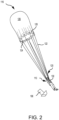
- parachute assembly 116 is illustrated in a deployed state.
- parachute assembly 116 may be used to increase a drag of, or otherwise decelerate, occupant 110, in response to occupant 110 being ejected, jumped, ditched, and/or dropped (collectively, "ejected") from an aircraft.
- Parachute assembly 116 may be configured to deploy upon separation of occupant 110 from ejection seat 106. Stated differently, in various embodiments, deployment of parachute assembly 116 may be configured to separate occupant 110 from ejection seat 106.
- Parachute assembly 116 may comprise a canopy 126, suspension lines 122, and a set of risers 120.
- canopy 126 may open to increase drag, or otherwise decelerate, occupant 110.
- Canopy 126 may comprise any suitable type of canopy and any suitable type of material, such as, for example, canvas, silk, nylon, aramid fiber (e.g., KEVLAR°), polyethylene terephthalate, and/or the like.
- Suspension lines 122 may be coupled to canopy 126 using any suitable attachment technique, such as, for example, through stitching. Suspension lines 122 may be configured to at least partially stabilize deployed canopy 126.
- parachute assembly 116 may include one or more reefing line(s) 124.
- Reefing line 124 may be coupled to canopy 126 proximate a circumferential edge 128 of canopy 126. Reefing line 124 may also be coupled to suspension lines 122. Reefing line 124 is configured to restrict expansion of canopy 126 such that canopy 126 opens in stages. For example, reefing line 124 may be cut, or otherwise severed, at a preselected time after deployment of canopy 126. Prior to cutting reefing line 124, canopy 126 is held at a first, restricted diameter. After reefing line 124 is severed, canopy 126 is able to open further and its diameter increases. Opening canopy 126 in stages may reduce opening shock to parachute assembly 116.
- the time delay between deploying canopy 126 and severing reefing line 124 may comprise any suitable time delay based on properties of parachute assembly 116, the type of aircraft, and/or the load limitations of the object (e.g., occupant 110) being carried by parachute assembly 116.
- suspension lines 122 may be configured to connect canopy 126 to risers 120.
- Suspension lines 122 and risers 120 may comprise any suitable material.
- suspension lines 122 may comprise a tubular braided material that constricts in diameter under tension, such as, for example, nylon, or aramid fiber (e.g., KEVLAR ® ), among others.
- suspension lines 122 may each comprise a braided material, for example, braided nylon or aramid fiber (e.g., KEVLAR ® ), among others.
- Risers 120 may comprise a webbing formed from nylon, aramid fiber (e.g., KEVLAR ® ), and/or the like. Risers 120 may be configured to attach to a harness 130, or other structure, configured to secure occupant 110 to risers 120.
- parachute assembly 116 may comprise a plurality of risers 120 attached to harness 130.
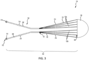
- Parachute assembly 116 comprises a canopy 126.
- Parachute assembly 116 also includes a suspension line assembly 302.
- Suspension line assembly 302 is comprised of suspension lines 122.
- suspension lines 122 may be attached to canopy 126 at a first end 304 of suspension line assembly 302.
- Each of suspension lines 122 may comprise a generally tubular shape that constricts in diameter under tension.
- Suspension line assembly 302 includes a first riser 306 and a second riser 308 of the set of risers 120.
- the first riser 306 and the second riser 308 may be formed by binding, or otherwise coupling, suspension lines 122 together.
- a first set of suspension lines 122a may be bound or coupled together to form first riser 306, and a second set of suspension lines 122b may be bound or coupled together to form second riser 308.
- Suspension lines 122a may be bound together via weaving, stitching, adhesive, and/or through any other suitable attachment method to form first riser 306.
- Suspension lines 122b may be bound together via weaving, stitching, adhesive, and/or through any other suitable attachment method to form second riser 308.
- parachute assembly 116 is illustrated as having 8 suspension lines 122, it is further contemplated and understood that parachute assembly 116 may include any number of suspension lines 122, such as, for example, 4 to 32 suspension lines 122, and the first riser 306 and the second riser 308 may be formed from any number of suspension lines 122, such as, for example, 8 to 16 suspension lines 122 per riser, or 2 to 6 suspension lines 122 per riser. Additionally, parachute assembly 116 may include more than 2 risers.
- the first riser 306 and the second riser 308 may be configured to attach an object, such as an ejections seat or an occupant harness, to parachute assembly 116.
- the first riser 306 and the second riser 308 may each comprise an attachment location 310.
- Attachment locations 310 may be proximate a second end 312 of suspension line assembly 302.
- the second end 312 is generally opposite the first end 304 and the canopy 126.
- suspension lines 122 may be coupled to the canopy 126 at the first end 304 and to an object at the second end 312.
- the attachment locations 310 may comprise any suitable attachment mechanism for securing an object to parachute assembly 116.
- the attachment locations 310 may comprise a loop created by each riser being bound to itself.
- one or more shock load attenuation devices 314 may be located in-line with each suspension line of the suspension lines 122. In various embodiments, one or more shock load attenuation devices 314 may also be located in-line with the first riser 306 and the second riser 308. In various embodiments, the one or more shock load attenuation devices 314 may also be located in-line with arm and leg restraints that restrain the arms and/or legs of the occupant 110 to the ejection seat 106. Accordingly, while the description hereafter references the shock load attenuation devices 314 in relation to the suspension lines 122, the various embodiments are not limited to the shock load attenuation devices 314 being implemented only with the suspension lines 122.
- each of the one or more shock load attenuation devices 314 may include crushable materials that, in response to the parachute being opened and begins to slow the occupant's descent, attenuates potentially dangerous loads that may be generated and imparted onto the occupant.
- the crushable materials enclosed within the shock load attenuation devices 314 are formed around the suspension lines 122 coupled to the canopy 126.
- the suspension lines 122, that pass within the shock load attenuation devices 314 are configured to slide and mechanically act on the crushable material, creating a compressive force. As the suspension lines 122 act upon the crushable material, absorbed energy may be reduced thereby decreasing the force exerted on the occupant of parachute assembly.
- shock load attenuation device 314 is illustrated, in accordance with various embodiments.
- shock load attenuation device 314 is configured to have two compartments, first compartment 316 and second compartment 318, divided by separator 320.
- the suspension line of the suspension lines 122 that passes within the shock load attenuation device 314 is formed by upper suspension line 122u, which is coupled to the first end 304 and the canopy 126 of FIG. 3 , and lower suspension line 122l, which is coupled to either the first riser 306 or the second riser 308 of FIG. 3 .
- the upper suspension line 122u may be configured in a loop such that the upper suspension line 122u couples to the first end 304 of the canopy 126, passes through the second compartment 318, loops around the lower suspension line 122l, passes back though the second compartment 318, and couples back to the first end 304 of the canopy 126 at the location from which it originated.
- a first end and a second end of the upper suspension line 122u couples to a same point of the canopy 126.
- the lower suspension line 122l may be configured in a loop such that the lower suspension line 122l couples either the first riser 306 or the second riser 308, passes through the first compartment 316, loops around the upper suspension line 122u, passes back though the first compartment 316, and couples back the respective one of either the first riser 306 or the second riser 308 from which it originated.
- a first end and a second end of the lower suspension line 122l couples to a same point on either the first riser 306 or the second riser 308.
- the portion of the upper suspension line 122u that loops around the lower suspension line 122l may be affixed to a first end 326 of the shock load attenuation device 314 using retainer 322.
- the portion of the lower suspension line 122l that loops around the upper suspension line 122u may be affixed to a second end 328 the shock load attenuation device 314 using retainer 324.
- the shock load attenuation device 314 device may be manufactured of a crushable material, such as, for example, nylon weave, polyester weave, aramid fiber (e.g., KEVLAR ® ) weave, duck cloth, canvas, metal mesh fabric, or multiple small elastomers, among others.
- the crushable material may include honeycomb type structures or corrugated materials, among others.
- the crushable materials are materials that offer some level of stiffness but can resist compression, and thereby absorb energy and reduce impulse, by mechanically deforming in a compression mode, or the like.
- separator 320, retainer 322, and retainer 324 may be formed using any suitable attachment technique, such as, for example, through stitching.
- the upper suspension line 122u is configured to slide respective from the lower suspension line 122l.
- a first force F1 is exerted on the upper suspension line 122u caused by the opening of the canopy 126 and a second force F2, which is opposite the first force F1, is exerted on the lower suspension line 122l caused by a load, i.e. the occupant 110 of FIG 2 .
- FIGS. 5A and 5B a shock load attenuation device 314 prior to and after being acted upon by load forces, respectively, are illustrated, in accordance with various embodiments.
- the shock load attenuation device 314 is shown prior to the parachute being opened and neither the first force F1 nor the second force F2 are acting upon the shock load attenuation device 314.
- FIG. 5A the shock load attenuation device 314 is shown prior to the parachute being opened and neither the first force F1 nor the second force F2 are acting upon the shock load attenuation device 314.
- the parachute is opened and the first force F1 acts on the upper suspension line 122u and the second force F2 acts on the lower suspension line 122l such that the looped end of the lower suspension line 122l slides along the upper suspension line 122u and the looped end of the upper suspension line slides along the lower suspension line 122l thereby mechanically acting upon and crushing the crushable material of the shock load attenuation device 314 thereby attenuating potentially dangerous loads that may be generated and imparted onto the occupant.
- references to "one embodiment,” “an embodiment,” “an example embodiment,” etc. indicate that the embodiment described may include a particular feature, structure, or characteristic, but every embodiment may not necessarily include the particular feature, structure, or characteristic. Moreover, such phrases are not necessarily referring to the same embodiment. Further, when a particular feature, structure, or characteristic is described in connection with an embodiment, it is submitted that it is within the knowledge of one skilled in the art to affect such feature, structure, or characteristic in connection with other embodiments whether or not explicitly described. After reading the description, it will be apparent to one skilled in the relevant art(s) how to implement the disclosure in alternative embodiments.
Landscapes
- Engineering & Computer Science (AREA)
- General Engineering & Computer Science (AREA)
- Mechanical Engineering (AREA)
- Aviation & Aerospace Engineering (AREA)
- Vibration Dampers (AREA)
Abstract
Description
- The present disclosure relates generally to parachute assemblies and, more specifically, to shock load attenuation for parachutes.
- Parachutes may be used to slow and stabilize an object (e.g., ejection seat or a person) supported by the parachute. Parachutes typically comprise a canopy to increase drag, and suspension lines coupled to the canopy. The suspension lines may be woven or otherwise bound to one another to form risers configured to attach the object to the parachute and stabilize the object to reduce rotation while under canopy. During the deployment of the parachute, potentially dangerous loads may be generated and imparted onto the occupant as a parachute is opened and begins to slow the occupant's descent. These loads, often referred to as "shock loads" or "snatch loads" present a safety risk to the occupant. The loads may also cause the suspension lines to break. Broken suspension lines tend to produce asymmetric load distribution, which may reduce stability, drag, and symmetry, which may transfer instability to the occupant and/or increase the chances of occupant injury.
- A shock load attenuation device for a parachute assembly is disclosed. The shock load attenuation device includes a crushable material; a first compartment in the crushable material surrounding a first line; and a second compartment in the crushable material surrounding a second line. In response to the first line being acted upon by a first force and the second line being acted upon by a second force, a first loop in the first line is configured to slide along the second line and a first loop in the second line is configured to slide along the first line, crushing the crushable material.
- In various embodiments, the first line passes through the first compartment and loops around the second line, and the second line passes through the second compartment and loops around the first line. In various embodiments, the shock load attenuation device further includes a separator configured to separate the first compartment from the second compartment. In various embodiments, the shock load attenuation device further includes a first retainer configured to affix the first loop of the first line to a first end of the crushable material. In various embodiments, the shock load attenuation device further includes a second retainer configured to affix the first loop of the second line to a second end of the crushable material.
- In various embodiments, a first end and a second end of the first line couples to a same location on a canopy of a parachute. In various embodiments, a first end and a second end of the second line couples to a same location on a riser of a parachute. In various embodiments, the first force is opposite the second force. In various embodiments, the crushable material is at least one or a combination of a nylon weave, polyester weave, aramid fiber weave, duck cloth, canvas, metal mesh fabric, or multiple small elastomers.
- Also disclosed herein is a parachute assembly. The parachute assembly includes a first line; a second line; and a shock load attenuation device. The shock load attenuation device includes a crushable material; a first compartment in the crushable material surrounding the first line; and a second compartment in the crushable material surrounding the second line. In response to the first line being acted upon by a first force and the second line being acted upon by a second force, a first loop in the first line is configured to slide along the second line and a first loop in the second line is configured to slide along the first line, crushing the crushable material.
- In various embodiments, the first line passes through the first compartment and loops around the second line, and the second line passes through the second compartment and loops around the first line. In various embodiments, the shock load attenuation device further includes a separator configured to separate the first compartment from the second compartment. In various embodiments, the shock load attenuation device further includes a first retainer configured to affix the first loop of the first line to a first end of the crushable material. In various embodiments, the shock load attenuation device further includes a second retainer configured to affix the first loop of the second line to a second end of the crushable material.
- In various embodiments, a first end and a second end of the first line couples to a same location on a canopy of a parachute. In various embodiments, a first end and a second end of the second line couples to a same location on a riser of a parachute. In various embodiments, the first force is opposite the second force. In various embodiments, the crushable material is at least one or a combination of a nylon weave, polyester weave, aramid fiber weave, duck cloth, canvas, metal mesh fabric, or multiple small elastomers.
- Also disclosed herein is a method of assembling a parachute assembly, comprising: passing a first end of a first line through a first compartment of a shock load attenuation device; looping the first end of the first line around a second line thereby forming a first loop of the first line; passing the first end of the first line back though the first compartment of the shock load attenuation device; coupling the first end and a second of the first line to a same location on a canopy of a parachute of the parachute assembly; passing a first end of the second line through a second compartment of the shock load attenuation device; looping the first end of the second line around the first line thereby forming a first loop of the second line; passing the first end of the second line back though the second compartment of the shock load attenuation device; and coupling the first end and a second of the second line to a same location on a riser of the parachute assembly, wherein, when the first line is acted upon by a first force and the second line is acted upon by a second force, the first loop in the first line is configured to slide along the second line and the first loop in the second line is configured to slide along the first line crushing a crushable material of the shock load attenuation device. In various embodiments, the crushable material is at least one or a combination of a nylon weave, polyester weave, aramid fiber weave, duck cloth, canvas, metal mesh fabric, or multiple small elastomers.
- The subject matter of the present disclosure is particularly pointed out and distinctly claimed in the concluding portion of the specification. A more complete understanding of the present disclosure, however, may best be obtained by referring to the detailed description and claims when considered in connection with the drawing figures, wherein like numerals denote like elements.
-
FIG. 1 illustrates an ejection seat being launched from an aircraft cockpit, in accordance with various embodiments. -
FIG. 2 illustrates a parachute assembly in a deployed state after separation of the occupant from the ejection seat, in accordance with various embodiments. -
FIG. 3 illustrates a parachute having shock load attenuation devices, in accordance with various embodiments. -
FIG. 4 illustrates a shock load attenuation device, in accordance with various embodiments. -
FIGS. 5A and 5B illustrate a shock load attenuation device prior to and after being acted upon by load forces, respectively, in accordance with various embodiments. - The detailed description of embodiments herein makes reference to the accompanying drawings, which show embodiments by way of illustration. While these embodiments are described in sufficient detail to enable those skilled in the art to practice the disclosure, it should be understood that other embodiments may be realized and that logical, chemical, and mechanical changes may be made without departing from the spirit and scope of the disclosure. Thus, the detailed description herein is presented for purposes of illustration only and not for limitation. For example, any reference to singular includes plural embodiments, and any reference to more than one component or step may include a singular embodiment or step. Also, any reference to attached, fixed, connected or the like may include permanent, removable, temporary, partial, full and/or any other possible attachment option. Further, any steps in a method discussed herein may be performed in any suitable order or combination.
- Disclosed herein is a parachute assembly including shock load attenuators. In accordance with various embodiments, the shock load attenuators include crushable materials to attenuate loads. The crushable materials, in various embodiments, are enclosed within a device that is formed around the suspension, riser, or restraint lines and coupled to the canopy. The suspension, riser, or restraint lines, in various embodiments, are configured within the device so that the suspension, riser, or restraint lines may slide and mechanically act on the crushable material. In various embodiments, additional mechanisms may be provided that reduce higher load impacts or activate the device as a designated load is approached. As the suspension, riser, or restraint lines act upon the crushable material, absorbed energy may be reduced, thereby decreasing the force exerted on the occupant of parachute assembly.
- With reference to
FIG. 1 , anaircraft ejection system 100 is shown. In accordance with various embodiments,aircraft ejection system 100 may be installed in anaircraft 102 to safely expel anejection seat 106 and anoccupant 110 ofejection seat 106 from acockpit 104 ofaircraft 102.Ejection seat 106 may be urged fromcockpit 104 by apropulsion system 108.Aircraft ejection system 100 may include aparachute assembly 116. In various embodiments, prior to deployment ofparachute assembly 116, a portion ofparachute assembly 116 may be stored withinejection seat 106. - With reference to
FIG. 2 ,parachute assembly 116 is illustrated in a deployed state. In accordance with various embodiments,parachute assembly 116 may be used to increase a drag of, or otherwise decelerate,occupant 110, in response tooccupant 110 being ejected, jumped, ditched, and/or dropped (collectively, "ejected") from an aircraft.Parachute assembly 116 may be configured to deploy upon separation ofoccupant 110 fromejection seat 106. Stated differently, in various embodiments, deployment ofparachute assembly 116 may be configured toseparate occupant 110 fromejection seat 106.Parachute assembly 116 may comprise acanopy 126,suspension lines 122, and a set ofrisers 120. - Upon deployment of
parachute assembly 116,canopy 126 may open to increase drag, or otherwise decelerate,occupant 110.Canopy 126 may comprise any suitable type of canopy and any suitable type of material, such as, for example, canvas, silk, nylon, aramid fiber (e.g., KEVLAR°), polyethylene terephthalate, and/or the like.Suspension lines 122 may be coupled tocanopy 126 using any suitable attachment technique, such as, for example, through stitching.Suspension lines 122 may be configured to at least partially stabilize deployedcanopy 126. In various embodiments,parachute assembly 116 may include one or more reefing line(s) 124.Reefing line 124 may be coupled tocanopy 126 proximate acircumferential edge 128 ofcanopy 126.Reefing line 124 may also be coupled to suspension lines 122.Reefing line 124 is configured to restrict expansion ofcanopy 126 such thatcanopy 126 opens in stages. For example,reefing line 124 may be cut, or otherwise severed, at a preselected time after deployment ofcanopy 126. Prior to cuttingreefing line 124,canopy 126 is held at a first, restricted diameter. After reefingline 124 is severed,canopy 126 is able to open further and its diameter increases. Openingcanopy 126 in stages may reduce opening shock toparachute assembly 116. The time delay between deployingcanopy 126 and severingreefing line 124 may comprise any suitable time delay based on properties ofparachute assembly 116, the type of aircraft, and/or the load limitations of the object (e.g., occupant 110) being carried byparachute assembly 116. - In various embodiments,
suspension lines 122 may be configured to connectcanopy 126 torisers 120.Suspension lines 122 andrisers 120 may comprise any suitable material. In various embodiments,suspension lines 122 may comprise a tubular braided material that constricts in diameter under tension, such as, for example, nylon, or aramid fiber (e.g., KEVLAR®), among others. In various embodiments,suspension lines 122 may each comprise a braided material, for example, braided nylon or aramid fiber (e.g., KEVLAR®), among others.Risers 120 may comprise a webbing formed from nylon, aramid fiber (e.g., KEVLAR®), and/or the like.Risers 120 may be configured to attach to aharness 130, or other structure, configured to secureoccupant 110 to risers 120. In various embodiments,parachute assembly 116 may comprise a plurality ofrisers 120 attached to harness 130. - With reference to
FIG. 3 , aparachute assembly 116 having shock load attenuation devices is illustrated, in accordance with various embodiments.Parachute assembly 116 comprises acanopy 126.Parachute assembly 116 also includes asuspension line assembly 302.Suspension line assembly 302 is comprised of suspension lines 122. In various embodiments,suspension lines 122 may be attached tocanopy 126 at afirst end 304 ofsuspension line assembly 302. Each ofsuspension lines 122 may comprise a generally tubular shape that constricts in diameter under tension. -
Suspension line assembly 302 includes afirst riser 306 and asecond riser 308 of the set ofrisers 120. Thefirst riser 306 and thesecond riser 308 may be formed by binding, or otherwise coupling,suspension lines 122 together. For example, a first set ofsuspension lines 122a may be bound or coupled together to formfirst riser 306, and a second set ofsuspension lines 122b may be bound or coupled together to formsecond riser 308.Suspension lines 122a may be bound together via weaving, stitching, adhesive, and/or through any other suitable attachment method to formfirst riser 306.Suspension lines 122b may be bound together via weaving, stitching, adhesive, and/or through any other suitable attachment method to formsecond riser 308. Whileparachute assembly 116 is illustrated as having 8suspension lines 122, it is further contemplated and understood thatparachute assembly 116 may include any number ofsuspension lines 122, such as, for example, 4 to 32suspension lines 122, and thefirst riser 306 and thesecond riser 308 may be formed from any number ofsuspension lines 122, such as, for example, 8 to 16suspension lines 122 per riser, or 2 to 6suspension lines 122 per riser. Additionally,parachute assembly 116 may include more than 2 risers. - The
first riser 306 and thesecond riser 308 may be configured to attach an object, such as an ejections seat or an occupant harness, to parachuteassembly 116. In various embodiments, thefirst riser 306 and thesecond riser 308 may each comprise anattachment location 310.Attachment locations 310 may be proximate asecond end 312 ofsuspension line assembly 302. Thesecond end 312 is generally opposite thefirst end 304 and thecanopy 126. Stated differently,suspension lines 122 may be coupled to thecanopy 126 at thefirst end 304 and to an object at thesecond end 312. Theattachment locations 310 may comprise any suitable attachment mechanism for securing an object to parachuteassembly 116. In various embodiments, theattachment locations 310 may comprise a loop created by each riser being bound to itself. - In various embodiments, one or more shock
load attenuation devices 314 may be located in-line with each suspension line of the suspension lines 122. In various embodiments, one or more shockload attenuation devices 314 may also be located in-line with thefirst riser 306 and thesecond riser 308. In various embodiments, the one or more shockload attenuation devices 314 may also be located in-line with arm and leg restraints that restrain the arms and/or legs of theoccupant 110 to theejection seat 106. Accordingly, while the description hereafter references the shockload attenuation devices 314 in relation to thesuspension lines 122, the various embodiments are not limited to the shockload attenuation devices 314 being implemented only with the suspension lines 122. - In various embodiments, each of the one or more shock
load attenuation devices 314 may include crushable materials that, in response to the parachute being opened and begins to slow the occupant's descent, attenuates potentially dangerous loads that may be generated and imparted onto the occupant. In various embodiments, the crushable materials enclosed within the shockload attenuation devices 314 are formed around thesuspension lines 122 coupled to thecanopy 126. As will be described hereafter, in various embodiments, thesuspension lines 122, that pass within the shockload attenuation devices 314 are configured to slide and mechanically act on the crushable material, creating a compressive force. As thesuspension lines 122 act upon the crushable material, absorbed energy may be reduced thereby decreasing the force exerted on the occupant of parachute assembly. - With reference to
FIG. 4 , a shockload attenuation device 314 is illustrated, in accordance with various embodiments. In various embodiments, shockload attenuation device 314 is configured to have two compartments,first compartment 316 andsecond compartment 318, divided byseparator 320. In various embodiments, the suspension line of thesuspension lines 122 that passes within the shockload attenuation device 314 is formed byupper suspension line 122u, which is coupled to thefirst end 304 and thecanopy 126 ofFIG. 3 , and lower suspension line 122l, which is coupled to either thefirst riser 306 or thesecond riser 308 ofFIG. 3 . In various embodiments, theupper suspension line 122u may be configured in a loop such that theupper suspension line 122u couples to thefirst end 304 of thecanopy 126, passes through thesecond compartment 318, loops around the lower suspension line 122l, passes back though thesecond compartment 318, and couples back to thefirst end 304 of thecanopy 126 at the location from which it originated. In that regard, a first end and a second end of theupper suspension line 122u couples to a same point of thecanopy 126. In various embodiments, the lower suspension line 122l may be configured in a loop such that the lower suspension line 122l couples either thefirst riser 306 or thesecond riser 308, passes through thefirst compartment 316, loops around theupper suspension line 122u, passes back though thefirst compartment 316, and couples back the respective one of either thefirst riser 306 or thesecond riser 308 from which it originated. In that regard, a first end and a second end of the lower suspension line 122l couples to a same point on either thefirst riser 306 or thesecond riser 308. In various embodiments, the portion of theupper suspension line 122u that loops around the lower suspension line 122l may be affixed to afirst end 326 of the shockload attenuation device 314 usingretainer 322. Similarly, in various embodiments, the portion of the lower suspension line 122l that loops around theupper suspension line 122u may be affixed to asecond end 328 the shockload attenuation device 314 usingretainer 324. - In various embodiments, the shock
load attenuation device 314 device may be manufactured of a crushable material, such as, for example, nylon weave, polyester weave, aramid fiber (e.g., KEVLAR®) weave, duck cloth, canvas, metal mesh fabric, or multiple small elastomers, among others. In various embodiments, the crushable material may include honeycomb type structures or corrugated materials, among others. In that regard, the crushable materials are materials that offer some level of stiffness but can resist compression, and thereby absorb energy and reduce impulse, by mechanically deforming in a compression mode, or the like. In that regard, in various embodiments,separator 320,retainer 322, andretainer 324 may be formed using any suitable attachment technique, such as, for example, through stitching. In various embodiments, by formingseparator 320 to separate theupper suspension line 122u from thelower suspension line 1221 and by retaining theupper suspension line 122u and the lower suspension line 122l using theretainer 322 and theretainer 324, respectively, theupper suspension line 122u is configured to slide respective from the lower suspension line 122l. - In various embodiments, in response to the parachute being opened and beginning to slow the occupant's descent, a first force F1 is exerted on the
upper suspension line 122u caused by the opening of thecanopy 126 and a second force F2, which is opposite the first force F1, is exerted on the lower suspension line 122l caused by a load, i.e. theoccupant 110 ofFIG 2 . In that regard, when the parachute is opened and the first force F1 and the second force F2 act against each other, the looped end of the lower suspension line 122l slides along theupper suspension line 122u, and the looped end of the upper suspension line slides along the lower suspension line 122l thereby mechanically acting upon and crushing the crushable material and thereby attenuating potentially dangerous loads that may be generated and imparted onto the occupant. - With reference to
FIGS. 5A and 5B , a shockload attenuation device 314 prior to and after being acted upon by load forces, respectively, are illustrated, in accordance with various embodiments. InFIG. 5A , the shockload attenuation device 314 is shown prior to the parachute being opened and neither the first force F1 nor the second force F2 are acting upon the shockload attenuation device 314. InFIG. 5B , the parachute is opened and the first force F1 acts on theupper suspension line 122u and the second force F2 acts on the lower suspension line 122l such that the looped end of the lower suspension line 122l slides along theupper suspension line 122u and the looped end of the upper suspension line slides along the lower suspension line 122l thereby mechanically acting upon and crushing the crushable material of the shockload attenuation device 314 thereby attenuating potentially dangerous loads that may be generated and imparted onto the occupant. - Benefits and other advantages have been described herein with regard to specific embodiments. Furthermore, the connecting lines shown in the various figures contained herein are intended to represent exemplary functional relationships and/or physical couplings between the various elements. It should be noted that many alternative or additional functional relationships or physical connections may be present in a practical system. However, the benefits, advantages, solutions to problems, and any elements that may cause any benefit, advantage, or solution to occur or become more pronounced are not to be construed as critical, required, or essential features or elements of the disclosure. The scope of the disclosure is accordingly to be limited by nothing other than the appended claims, in which reference to an element in the singular is not intended to mean "one and only one" unless explicitly so stated, but rather "one or more." Moreover, where a phrase similar to "at least one of A, B, or C" is used in the claims, it is intended that the phrase be interpreted to mean that A alone may be present in an embodiment, B alone may be present in an embodiment, C alone may be present in an embodiment, or that any combination of the elements A, B and C may be present in a single embodiment; for example, A and B, A and C, B and C, or A and B and C.
- Systems, methods, and apparatus are provided herein. In the detailed description herein, references to "one embodiment," "an embodiment," "an example embodiment," etc., indicate that the embodiment described may include a particular feature, structure, or characteristic, but every embodiment may not necessarily include the particular feature, structure, or characteristic. Moreover, such phrases are not necessarily referring to the same embodiment. Further, when a particular feature, structure, or characteristic is described in connection with an embodiment, it is submitted that it is within the knowledge of one skilled in the art to affect such feature, structure, or characteristic in connection with other embodiments whether or not explicitly described. After reading the description, it will be apparent to one skilled in the relevant art(s) how to implement the disclosure in alternative embodiments.
- Furthermore, no element, component, or method step in the present disclosure is intended to be dedicated to the public regardless of whether the element, component, or method step is explicitly recited in the claims. No claim element herein is intended to invoke 35 U.S.C. 112(f) unless the element is expressly recited using the phrase "means for." As used herein, the terms "comprises," "comprising," or any other variation thereof, are intended to cover a non-exclusive inclusion, such that a process, method, article, or apparatus that comprises a list of elements does not include only those elements but may include other elements not expressly listed or inherent to such process, method, article, or apparatus.
Claims (15)
- A shock load attenuation device for a parachute assembly, the shock load attenuation device comprising:a crushable material;a first compartment (316) in the crushable material surrounding a first line; anda second compartment (318) in the crushable material surrounding a second line,wherein, in response to the first line being acted upon by a first force and the second line being acted upon by a second force, a first loop in the first line is configured to slide along the second line and a first loop in the second line is configured to slide along the first line, crushing the crushable material.
- The shock load attenuation device of claim 1,wherein the first line passes through the first compartment (316) and loops around the second line, andwherein the second line passes through the second compartment (318) and loops around the first line.
- The shock load attenuation device of claim 1, further comprising:
a separator configured to separate the first compartment (316) from the second compartment (318), and/or further comprising:
a first retainer configured to affix the first loop of the first line to a first end of the crushable material. - The shock load attenuation device of any preceding claim, further comprising:
a second retainer configured to affix the first loop of the second line to a second end of the crushable material. - The shock load attenuation device of any preceding claim, wherein a first end and a second end of the first line couples to a same location on a canopy of a parachute, or wherein a first end and a second end of the second line couples to a same location on a riser of a parachute.
- The shock load attenuation device of any preceding claim, wherein the first force is opposite the second force.
- The shock load attenuation device of any preceding claim, wherein the crushable material is at least one or a combination of a nylon weave, polyester weave, aramid fiber weave, duck cloth, canvas, metal mesh fabric, or multiple small elastomers.
- A parachute assembly, comprising:a first line;a second line; anda shock load attenuation device, wherein the shock load attenuation device comprises:a crushable material;a first compartment (316) in the crushable material surrounding the first line; anda second compartment (318) in the crushable material surrounding the second line,wherein, in response to the first line being acted upon by a first force and the second line being acted upon by a second force, a first loop in the first line is configured to slide along the second line and a first loop in the second line is configured to slide along the first line, crushing the crushable material.
- The parachute assembly of claim 8,wherein the first line passes through the first compartment (316) and loops around the second line, andwherein the second line passes through the second compartment (318) and loops around the first line.
- The parachute assembly of claim 8 or 9, wherein the shock load attenuation device further comprises:
a separator configured to separate the first compartment (316) from the second compartment (318). - The parachute assembly of any of claims 8 to 10, wherein the shock load attenuation device further comprises:
a first retainer configured to affix the first loop of the first line to a first end of the crushable material, or wherein the shock load attenuation device further comprises:
a second retainer configured to affix the first loop of the second line to a second end of the crushable material. - The parachute assembly of any of claims 8 to 11, wherein a first end and a second end of the first line couples to a same location on a canopy of a parachute, or wherein a first end and a second end of the second line couples to a same location on a riser of a parachute.
- The parachute assembly of any of claims 8 to 12, wherein the first force is opposite the second force, and/or wherein the crushable material is at least one or a combination of a nylon weave, polyester weave, aramid fiber weave, duck cloth, canvas, metal mesh fabric, or multiple small elastomers.
- A method of assembling a parachute assembly, comprising:passing a first end of a first line through a first compartment (316) of a shock load attenuation device;looping the first end of the first line around a second line thereby forming a first loop of the first line;passing the first end of the first line back though the first compartment (316) of the shock load attenuation device;coupling the first end and a second of the first line to a same location on a canopy of a parachute of the parachute assembly;passing a first end of the second line through a second compartment (318) of the shock load attenuation device;looping the first end of the second line around the first line thereby forming a first loop of the second line;passing the first end of the second line back though the second compartment (318) of the shock load attenuation device; andcoupling the first end and a second of the second line to a same location on a riser of the parachute assembly,wherein, when the first line is acted upon by a first force and the second line is acted upon by a second force, the first loop in the first line is configured to slide along the second line and the first loop in the second line is configured to slide along the first line crushing a crushable material of the shock load attenuation device.
- The method of claim 14, wherein the crushable material is at least one or a combination of a nylon weave, polyester weave, aramid fiber weave, duck cloth, canvas, metal mesh fabric, or multiple small elastomers.
Applications Claiming Priority (1)
| Application Number | Priority Date | Filing Date | Title |
|---|---|---|---|
| US18/176,996 US12157576B2 (en) | 2023-03-01 | 2023-03-01 | Shock load attenuation |
Publications (2)
| Publication Number | Publication Date |
|---|---|
| EP4424600A1 true EP4424600A1 (en) | 2024-09-04 |
| EP4424600B1 EP4424600B1 (en) | 2025-10-22 |
Family
ID=90123092
Family Applications (1)
| Application Number | Title | Priority Date | Filing Date |
|---|---|---|---|
| EP24160844.7A Active EP4424600B1 (en) | 2023-03-01 | 2024-03-01 | Shock load attenuation |
Country Status (2)
| Country | Link |
|---|---|
| US (1) | US12157576B2 (en) |
| EP (1) | EP4424600B1 (en) |
Families Citing this family (1)
| Publication number | Priority date | Publication date | Assignee | Title |
|---|---|---|---|---|
| US20250346357A1 (en) * | 2024-05-08 | 2025-11-13 | Ami Industries, Inc. | Parachute systems and energy attenuating drogue systems thereof |
Citations (5)
| Publication number | Priority date | Publication date | Assignee | Title |
|---|---|---|---|---|
| US3444957A (en) * | 1967-12-13 | 1969-05-20 | Rose Mfg Co | Shock absorber for safety belt |
| US3804698A (en) * | 1970-05-25 | 1974-04-16 | Us Navy | Adhesively releasable and reusable shock load absorbing system |
| US11040778B2 (en) * | 2018-11-16 | 2021-06-22 | Goodrich Corporation | Multi-staged suspension line attenuator |
| US11225329B2 (en) * | 2019-02-19 | 2022-01-18 | Goodrich Corporation | Dampening risers for parachutes |
| US20220033095A1 (en) * | 2020-08-03 | 2022-02-03 | Ami Industries, Inc. | Drogue parachute assemblies with elastomeric insert sleeves |
Family Cites Families (10)
| Publication number | Priority date | Publication date | Assignee | Title |
|---|---|---|---|---|
| US2578753A (en) * | 1944-08-18 | 1951-12-18 | Smith William Herbert | Parachute load cushioning mechanism |
| GB587983A (en) | 1944-08-18 | 1947-05-12 | William Herbert Smith | Parachute mechanism |
| DE2923327C2 (en) * | 1979-06-08 | 1981-01-08 | Hoermann Kg Amshausen, 4803 Steinhagen | Device for relieving the weight of a movable gate |
| FR2673253B1 (en) * | 1991-02-26 | 1994-04-08 | Sisyphe Sarl | DEVICE FOR ABSORBING ENERGY BY THE DEFORMATION OF MATERIALS. |
| US5803439A (en) * | 1994-05-25 | 1998-09-08 | Gilmore; Peter | Apparatus and method for reducing shocks in a line |
| DE19520724A1 (en) * | 1995-06-12 | 1996-12-19 | Trumer Schutz Bauten Gmbh | Rockfall etc safety barrier in rope design |
| ES2251318B1 (en) * | 2004-10-15 | 2007-02-16 | Malla Talud Cantabria, S.L. | IMPACT SHOCK ABSORBER DEVICE IN HEALTH PROTECTION SYSTEMS. |
| FR2959288B1 (en) * | 2010-04-21 | 2012-06-22 | Geotechnique Et Travaux Speciaux | DEVICE FOR DISSIPATING ENERGY FOR A CABLE AND INSTALLATION COMPRISING SUCH A DEVICE |
| ES2428790B1 (en) * | 2013-08-07 | 2014-09-04 | Andrea Pereiro Naveira | Damper device for mooring boats by means of ends and hook system at the end |
| US11299281B2 (en) * | 2020-08-03 | 2022-04-12 | Ami Industries, Inc. | Parachute assemblies with elastomeric inserts |
-
2023
- 2023-03-01 US US18/176,996 patent/US12157576B2/en active Active
-
2024
- 2024-03-01 EP EP24160844.7A patent/EP4424600B1/en active Active
Patent Citations (5)
| Publication number | Priority date | Publication date | Assignee | Title |
|---|---|---|---|---|
| US3444957A (en) * | 1967-12-13 | 1969-05-20 | Rose Mfg Co | Shock absorber for safety belt |
| US3804698A (en) * | 1970-05-25 | 1974-04-16 | Us Navy | Adhesively releasable and reusable shock load absorbing system |
| US11040778B2 (en) * | 2018-11-16 | 2021-06-22 | Goodrich Corporation | Multi-staged suspension line attenuator |
| US11225329B2 (en) * | 2019-02-19 | 2022-01-18 | Goodrich Corporation | Dampening risers for parachutes |
| US20220033095A1 (en) * | 2020-08-03 | 2022-02-03 | Ami Industries, Inc. | Drogue parachute assemblies with elastomeric insert sleeves |
Also Published As
| Publication number | Publication date |
|---|---|
| US12157576B2 (en) | 2024-12-03 |
| EP4424600B1 (en) | 2025-10-22 |
| US20240294263A1 (en) | 2024-09-05 |
Similar Documents
| Publication | Publication Date | Title |
|---|---|---|
| US11027851B2 (en) | Head restraint for parachute assemblies | |
| US10946970B2 (en) | Systems for removal of parachute assembly head restraints | |
| US10099792B1 (en) | Parachute tow and release system with canopy extraction controlled by drag surface | |
| US11021256B2 (en) | Seat back head restrain for parachute assemblies | |
| US11685535B2 (en) | Multi-staged suspension line attenuator | |
| US20110121138A1 (en) | Low payload weight parachute release-away static line | |
| EP3395689B1 (en) | Yoke strap with shock absorber | |
| US11286052B2 (en) | Drogue parachute assemblies with elastomeric insert sleeves | |
| EP3348483A1 (en) | Shock absorbing evacuation system restraint | |
| US10065742B1 (en) | Parachute deployment system using decoupled tow and release lines | |
| EP4424600B1 (en) | Shock load attenuation | |
| US5618011A (en) | Load securing and releasing system | |
| US11299281B2 (en) | Parachute assemblies with elastomeric inserts | |
| US10464681B1 (en) | Parachute architecture for low-altitude VTOL aircraft | |
| US10053221B2 (en) | Multi-staged suspension line length parachutes | |
| US12286233B2 (en) | Parachute assemblies with multi-stage reefing | |
| US20210309377A1 (en) | Energy absorbing device adapted for a mild impact of an aircraft, uav, equipped with a parachute | |
| US11465761B2 (en) | Neck protection system for parachute assemblies |
Legal Events
| Date | Code | Title | Description |
|---|---|---|---|
| PUAI | Public reference made under article 153(3) epc to a published international application that has entered the european phase |
Free format text: ORIGINAL CODE: 0009012 |
|
| STAA | Information on the status of an ep patent application or granted ep patent |
Free format text: STATUS: THE APPLICATION HAS BEEN PUBLISHED |
|
| AK | Designated contracting states |
Kind code of ref document: A1 Designated state(s): AL AT BE BG CH CY CZ DE DK EE ES FI FR GB GR HR HU IE IS IT LI LT LU LV MC ME MK MT NL NO PL PT RO RS SE SI SK SM TR |
|
| STAA | Information on the status of an ep patent application or granted ep patent |
Free format text: STATUS: REQUEST FOR EXAMINATION WAS MADE |
|
| 17P | Request for examination filed |
Effective date: 20250227 |
|
| GRAP | Despatch of communication of intention to grant a patent |
Free format text: ORIGINAL CODE: EPIDOSNIGR1 |
|
| STAA | Information on the status of an ep patent application or granted ep patent |
Free format text: STATUS: GRANT OF PATENT IS INTENDED |
|
| INTG | Intention to grant announced |
Effective date: 20250519 |
|
| GRAS | Grant fee paid |
Free format text: ORIGINAL CODE: EPIDOSNIGR3 |
|
| GRAA | (expected) grant |
Free format text: ORIGINAL CODE: 0009210 |
|
| STAA | Information on the status of an ep patent application or granted ep patent |
Free format text: STATUS: THE PATENT HAS BEEN GRANTED |
|
| AK | Designated contracting states |
Kind code of ref document: B1 Designated state(s): AL AT BE BG CH CY CZ DE DK EE ES FI FR GB GR HR HU IE IS IT LI LT LU LV MC ME MK MT NL NO PL PT RO RS SE SI SK SM TR |
|
| REG | Reference to a national code |
Ref country code: CH Ref legal event code: F10 Free format text: ST27 STATUS EVENT CODE: U-0-0-F10-F00 (AS PROVIDED BY THE NATIONAL OFFICE) Effective date: 20251022 Ref country code: GB Ref legal event code: FG4D |
|
| REG | Reference to a national code |
Ref country code: DE Ref legal event code: R096 Ref document number: 602024000978 Country of ref document: DE |
|
| REG | Reference to a national code |
Ref country code: IE Ref legal event code: FG4D |
|
| REG | Reference to a national code |
Ref country code: NL Ref legal event code: MP Effective date: 20251022 |
|
| PG25 | Lapsed in a contracting state [announced via postgrant information from national office to epo] |
Ref country code: NL Free format text: LAPSE BECAUSE OF FAILURE TO SUBMIT A TRANSLATION OF THE DESCRIPTION OR TO PAY THE FEE WITHIN THE PRESCRIBED TIME-LIMIT Effective date: 20251022 |
|
| PG25 | Lapsed in a contracting state [announced via postgrant information from national office to epo] |
Ref country code: ES Free format text: LAPSE BECAUSE OF FAILURE TO SUBMIT A TRANSLATION OF THE DESCRIPTION OR TO PAY THE FEE WITHIN THE PRESCRIBED TIME-LIMIT Effective date: 20251022 |
|
| REG | Reference to a national code |
Ref country code: LT Ref legal event code: MG9D |
|
| PG25 | Lapsed in a contracting state [announced via postgrant information from national office to epo] |
Ref country code: NO Free format text: LAPSE BECAUSE OF FAILURE TO SUBMIT A TRANSLATION OF THE DESCRIPTION OR TO PAY THE FEE WITHIN THE PRESCRIBED TIME-LIMIT Effective date: 20260122 |
|
| PGFP | Annual fee paid to national office [announced via postgrant information from national office to epo] |
Ref country code: DE Payment date: 20260219 Year of fee payment: 3 |
|
| PG25 | Lapsed in a contracting state [announced via postgrant information from national office to epo] |
Ref country code: AT Free format text: LAPSE BECAUSE OF FAILURE TO SUBMIT A TRANSLATION OF THE DESCRIPTION OR TO PAY THE FEE WITHIN THE PRESCRIBED TIME-LIMIT Effective date: 20251022 Ref country code: HR Free format text: LAPSE BECAUSE OF FAILURE TO SUBMIT A TRANSLATION OF THE DESCRIPTION OR TO PAY THE FEE WITHIN THE PRESCRIBED TIME-LIMIT Effective date: 20251022 Ref country code: FI Free format text: LAPSE BECAUSE OF FAILURE TO SUBMIT A TRANSLATION OF THE DESCRIPTION OR TO PAY THE FEE WITHIN THE PRESCRIBED TIME-LIMIT Effective date: 20251022 |
|
| PGFP | Annual fee paid to national office [announced via postgrant information from national office to epo] |
Ref country code: AT Payment date: 20260301 Year of fee payment: 3 |
|
| REG | Reference to a national code |
Ref country code: AT Ref legal event code: MK05 Ref document number: 1848964 Country of ref document: AT Kind code of ref document: T Effective date: 20251022 |
|
| PG25 | Lapsed in a contracting state [announced via postgrant information from national office to epo] |
Ref country code: RS Free format text: LAPSE BECAUSE OF FAILURE TO SUBMIT A TRANSLATION OF THE DESCRIPTION OR TO PAY THE FEE WITHIN THE PRESCRIBED TIME-LIMIT Effective date: 20260122 |
|
| PG25 | Lapsed in a contracting state [announced via postgrant information from national office to epo] |
Ref country code: IS Free format text: LAPSE BECAUSE OF FAILURE TO SUBMIT A TRANSLATION OF THE DESCRIPTION OR TO PAY THE FEE WITHIN THE PRESCRIBED TIME-LIMIT Effective date: 20260222 |
|
| PGFP | Annual fee paid to national office [announced via postgrant information from national office to epo] |
Ref country code: FR Payment date: 20260219 Year of fee payment: 3 |
|
| PG25 | Lapsed in a contracting state [announced via postgrant information from national office to epo] |
Ref country code: PT Free format text: LAPSE BECAUSE OF FAILURE TO SUBMIT A TRANSLATION OF THE DESCRIPTION OR TO PAY THE FEE WITHIN THE PRESCRIBED TIME-LIMIT Effective date: 20260223 |
|
| PG25 | Lapsed in a contracting state [announced via postgrant information from national office to epo] |
Ref country code: PL Free format text: LAPSE BECAUSE OF FAILURE TO SUBMIT A TRANSLATION OF THE DESCRIPTION OR TO PAY THE FEE WITHIN THE PRESCRIBED TIME-LIMIT Effective date: 20251022 |
|
| PG25 | Lapsed in a contracting state [announced via postgrant information from national office to epo] |
Ref country code: LV Free format text: LAPSE BECAUSE OF FAILURE TO SUBMIT A TRANSLATION OF THE DESCRIPTION OR TO PAY THE FEE WITHIN THE PRESCRIBED TIME-LIMIT Effective date: 20251022 |
|
| PG25 | Lapsed in a contracting state [announced via postgrant information from national office to epo] |
Ref country code: BG Free format text: LAPSE BECAUSE OF FAILURE TO SUBMIT A TRANSLATION OF THE DESCRIPTION OR TO PAY THE FEE WITHIN THE PRESCRIBED TIME-LIMIT Effective date: 20251022 |