EP4424566A1 - Motor vehicle and method for the reconfiguration of the motor vehicle - Google Patents
Motor vehicle and method for the reconfiguration of the motor vehicle Download PDFInfo
- Publication number
- EP4424566A1 EP4424566A1 EP24160437.0A EP24160437A EP4424566A1 EP 4424566 A1 EP4424566 A1 EP 4424566A1 EP 24160437 A EP24160437 A EP 24160437A EP 4424566 A1 EP4424566 A1 EP 4424566A1
- Authority
- EP
- European Patent Office
- Prior art keywords
- axis
- motor vehicle
- along
- configuration
- seat
- Prior art date
- Legal status (The legal status is an assumption and is not a legal conclusion. Google has not performed a legal analysis and makes no representation as to the accuracy of the status listed.)
- Granted
Links
Images



Classifications
-
- B—PERFORMING OPERATIONS; TRANSPORTING
- B62—LAND VEHICLES FOR TRAVELLING OTHERWISE THAN ON RAILS
- B62D—MOTOR VEHICLES; TRAILERS
- B62D1/00—Steering controls, i.e. means for initiating a change of direction of the vehicle
- B62D1/02—Steering controls, i.e. means for initiating a change of direction of the vehicle vehicle-mounted
- B62D1/16—Steering columns
- B62D1/18—Steering columns yieldable or adjustable, e.g. tiltable
-
- B—PERFORMING OPERATIONS; TRANSPORTING
- B62—LAND VEHICLES FOR TRAVELLING OTHERWISE THAN ON RAILS
- B62D—MOTOR VEHICLES; TRAILERS
- B62D1/00—Steering controls, i.e. means for initiating a change of direction of the vehicle
- B62D1/02—Steering controls, i.e. means for initiating a change of direction of the vehicle vehicle-mounted
- B62D1/16—Steering columns
- B62D1/18—Steering columns yieldable or adjustable, e.g. tiltable
- B62D1/184—Mechanisms for locking columns at selected positions
-
- B—PERFORMING OPERATIONS; TRANSPORTING
- B62—LAND VEHICLES FOR TRAVELLING OTHERWISE THAN ON RAILS
- B62D—MOTOR VEHICLES; TRAILERS
- B62D1/00—Steering controls, i.e. means for initiating a change of direction of the vehicle
- B62D1/02—Steering controls, i.e. means for initiating a change of direction of the vehicle vehicle-mounted
- B62D1/16—Steering columns
- B62D1/18—Steering columns yieldable or adjustable, e.g. tiltable
- B62D1/181—Steering columns yieldable or adjustable, e.g. tiltable with power actuated adjustment, e.g. with position memory
-
- B—PERFORMING OPERATIONS; TRANSPORTING
- B60—VEHICLES IN GENERAL
- B60K—ARRANGEMENT OR MOUNTING OF PROPULSION UNITS OR OF TRANSMISSIONS IN VEHICLES; ARRANGEMENT OR MOUNTING OF PLURAL DIVERSE PRIME-MOVERS IN VEHICLES; AUXILIARY DRIVES FOR VEHICLES; INSTRUMENTATION OR DASHBOARDS FOR VEHICLES; ARRANGEMENTS IN CONNECTION WITH COOLING, AIR INTAKE, GAS EXHAUST OR FUEL SUPPLY OF PROPULSION UNITS IN VEHICLES
- B60K26/00—Arrangement or mounting of propulsion-unit control devices in vehicles
- B60K26/02—Arrangement or mounting of propulsion-unit control devices in vehicles of initiating means or elements
-
- B—PERFORMING OPERATIONS; TRANSPORTING
- B60—VEHICLES IN GENERAL
- B60T—VEHICLE BRAKE CONTROL SYSTEMS OR PARTS THEREOF; BRAKE CONTROL SYSTEMS OR PARTS THEREOF, IN GENERAL; ARRANGEMENT OF BRAKING ELEMENTS ON VEHICLES IN GENERAL; PORTABLE DEVICES FOR PREVENTING UNWANTED MOVEMENT OF VEHICLES; VEHICLE MODIFICATIONS TO FACILITATE COOLING OF BRAKES
- B60T7/00—Brake-action initiating means
- B60T7/02—Brake-action initiating means for personal initiation
- B60T7/04—Brake-action initiating means for personal initiation foot actuated
- B60T7/06—Disposition of pedal
-
- B—PERFORMING OPERATIONS; TRANSPORTING
- B62—LAND VEHICLES FOR TRAVELLING OTHERWISE THAN ON RAILS
- B62D—MOTOR VEHICLES; TRAILERS
- B62D1/00—Steering controls, i.e. means for initiating a change of direction of the vehicle
- B62D1/02—Steering controls, i.e. means for initiating a change of direction of the vehicle vehicle-mounted
- B62D1/04—Hand wheels
-
- B—PERFORMING OPERATIONS; TRANSPORTING
- B62—LAND VEHICLES FOR TRAVELLING OTHERWISE THAN ON RAILS
- B62D—MOTOR VEHICLES; TRAILERS
- B62D1/00—Steering controls, i.e. means for initiating a change of direction of the vehicle
- B62D1/02—Steering controls, i.e. means for initiating a change of direction of the vehicle vehicle-mounted
- B62D1/16—Steering columns
- B62D1/18—Steering columns yieldable or adjustable, e.g. tiltable
- B62D1/183—Steering columns yieldable or adjustable, e.g. tiltable adjustable between in-use and out-of-use positions, e.g. to improve access
-
- B—PERFORMING OPERATIONS; TRANSPORTING
- B62—LAND VEHICLES FOR TRAVELLING OTHERWISE THAN ON RAILS
- B62D—MOTOR VEHICLES; TRAILERS
- B62D5/00—Power-assisted or power-driven steering
- B62D5/001—Mechanical components or aspects of steer-by-wire systems, not otherwise provided for in this maingroup
-
- B—PERFORMING OPERATIONS; TRANSPORTING
- B62—LAND VEHICLES FOR TRAVELLING OTHERWISE THAN ON RAILS
- B62D—MOTOR VEHICLES; TRAILERS
- B62D63/00—Motor vehicles or trailers not otherwise provided for
- B62D63/02—Motor vehicles
- B62D63/04—Component parts or accessories
Definitions
- the present invention relates to a motor vehicle and a method for the reconfiguration of the motor vehicle.
- motor vehicles comprise:
- the passenger compartment comprises a pair of front seats intended to be occupied by a driver and a passenger, respectively, and arranged side-by-side along a transversal direction of the motor vehicle orthogonal to a longitudinal direction defining a normal driving direction of the motor vehicle.
- the steering wheel and set of pedals are located in front of the driver's seat and substantially at a front left or right corner of the motor vehicle.
- passenger compartments are known to have the so-called 'single-seater' configuration.
- the passenger compartment comprises a single front seat positioned centrally in front of the steering wheel and the set of pedals.
- EP-A-3712035 discloses a steering assembly for a motor vehicle, in which a steering wheel can be moved to multiple positions for manual operation, in both manufacturing and use contexts.
- the object of the present invention is to provide a motor vehicle which allows the above-mentioned need to be met.
- the present invention also relates to a method for the reconfiguration of the motor vehicle as defined in claim 10.
- the numeral 1 indicates a motor vehicle comprising a body 2 defining a passenger compartment 3.
- the motor vehicle 1 further comprises ( Figure 5 ):
- the motor vehicle 1 further comprises ( Figure 1 ):
- the body 2 also comprises a pair of longitudinal, end door sills 23, 24, opposite each other.
- the door sills 23, 24 delimit the passenger compartment 3 and are adjacent to respective doors 8a, 8b when the doors 8a, 8b are in their closed positions.
- control members 10 which can be operated by the driver to set a forward trajectory of the motor vehicle 1 at a desired speed.
- control members 10 comprise:
- the set of pedals 12 comprises, in a nutshell and in a manner not described in detail as it is not necessary for the purpose of the present invention and only schematically illustrated in Figure 5 :
- the gearbox 20 and the clutch pedal are not present.
- gearbox 20 is semi-automatic or automatic, the clutch pedal is not present.
- the control members 10 are connected to the engine and wheels 6 and/or 7 through a drive-by-wire mode, thus producing a technology known in the industry as 'drive by wire' .
- ⁇ drive by wire' in the present description is intended to mean that the steering mechanism 11 has no physical or mechanical connection to the wheels 6, 7.
- the accelerator pedal 17 has no physical or mechanical connection to the engine 9, and the brake pedal 17 has no mechanical connection to the braking system 21.
- the passenger compartment 3 further comprises a front location 25 which defines a driver's seat.
- the location 25 is only schematically shown in Figure 1 .
- the passenger compartment 3 of the motor vehicle 1 is selectively movable, in a manner not described in detail because it is not necessary for the understanding of the present invention, between:
- the first seat is beside the door sill 23, and the second seat is beside the door sill 24.
- the first seat faces the steering mechanism 11 and the set of pedals 12 to allow the driver to operate the steering mechanism 11 and the set of pedals 12.
- the third seat is arranged in a central position between the door sills 23, 24 and faces the steering mechanism 11 and the set of pedals 12.
- the steering mechanism comprises ( Figures 2 to 4 ):
- the motor vehicle 1 also comprises a control unit 45 ( Figure 5 ) programmed to receive, as input, the operations requested from the steering mechanism 11 and set of pedals 12 and to generate, as output, appropriate control signals for the engine 9, gearbox 20, braking system 21 and wheels 6, 7.
- control unit 45 is programmed to control the rotation of the wheels 6, 7 by an angle associated with the angle of rotation of the steering wheel 62 around the axis H and in the same direction of rotation.
- the axis H is inclined with respect to the horizontal plane defined by the axes X, Y by an angle ⁇ ( Figure 4 ).
- the steering mechanism 11 also comprises a lever 65 that can be selectively moved between:
- the steering mechanism 11 can be moved along the axis Y to allow the motor vehicle 1 to be moved between the first and the second configuration.
- the steering mechanism 11 can be moved parallel to the axis Y between:
- the steering mechanism 11 is adjacent to the door sill 23 when it is arranged in the first position ( Figure 2 ). In this first position, a first distance between the steering wheel 62 and the door sill 23 is smaller than a second distance between the steering wheel 62 and the door sill 24. Said first and second distances are measured along the axis Y.
- a left-hand driving mode of the motor vehicle 1 is thus achieved.
- the steering wheel 62 is in a central position between the door sills 23, 24, when the steering mechanism 12 is in the second position ( Figure 3 ). In this second position, the steering wheel 62 is equally spaced apart from the door sills 23, 24 along the axis Y.
- the body 2 also comprises a pair of cross members 50, 51 elongated along respective axes J parallel to the axis Y and spaced apart along the axis X.
- the cross member 50 is arranged in front of the cross member 51.
- the cross members 50, 51 extend over the full width of the motor vehicle 1 along the axis Y and comprise:
- the cross members 50, 51 in turn, comprise:
- the passenger compartment 3 comprises a connection assembly 30 ( Figures 2 to 4 ) interposed between the steering mechanism 1 and the body 2 and designed to enable the translation of the steering mechanism 12 parallel to the axis Y between the first and the second position.
- connection assembly 30 in turn, comprises:
- the slide 76 in particular, is arranged in front of the slide 77.
- the guides 52, 53 and the slides 76, 77 are arranged at a top face 54 of the support body 60.
- the guides 52, 53 and the related slides 76, 77 are also arranged below the corresponding cross members 50, 51.
- the guides 52, 53 are arranged within respective seats 95, 97 of corresponding cross members 50, 51.
- the guides 52, 53 and the respective seats 95, 97 extend substantially to a width equal to half the width of the cross members 50, 51 and of the motor vehicle 1 along the axis Y, and comprise:
- the axis I is parallel to the axis H.
- the transmission assembly 56 comprises:
- connection element 90 comprises, in particular ( Figure 4 ):
- the motor vehicle 1 further comprises a system for moving the set of pedals 12 parallel to the axis Y, which is not described in detail as it is not part of the present invention.
- the above-mentioned movement system is operable to cause the movement of the set of pedals 12 parallel to the axis Y between:
- the set of pedals 12 is adjacent to the door sill 23 when it is in the third position.
- the set of pedals 12 is in a central position between the door sills 23, 24 when it is in the fourth position.
- the operation of the motor vehicle 1 is described starting from a condition in which the passenger compartment 3 is in the 'two-seater' configuration.
- the location 25 defines the first seat for the driver and the second seat for a passenger arranged side-by-side parallel to the axis Y.
- the first seat is beside the door sill 23, and the second seat is beside the door sill 24 parallel to the axis Y.
- the steering mechanism 11 and the set of pedals 12 are also arranged in the first and the third position, respectively, in which they face the first seat defined by the location 25 along the axis X.
- the first seat faces the steering mechanism 11 and the set of pedals 12 along the axis X to allow the driver to operate the steering mechanism 11 and the set of pedals 12 and thus control the forward trajectory and the speed of the motor vehicle 1.
- the operation of the electric motor 55 in the first direction causes the output shafts 70, 71 and the respective flexible shafts 80, 81 to rotate in the same first direction around the axis I.
- the steering mechanism 11 reaches the second position shown in Figure 3 in which it faces the third seat defined by the driving position.
- the steering mechanism 11 is in a central position between the door sills 23, 24 when it is in the second position.
- the system for moving the steering mechanism 11 is operated to cause the movement of the set of pedals 12 parallel to the axis Y until it reaches the fourth position.
- the set of pedals 12 is in a central position between the door sills 23, 24 and faces the third position defined by the location 25 when it is in the fourth position.
- the location 25 is reconfigured so as to only define the third seat for the driver, which is not necessary for the understanding of the present invention.
- the single third seat is arranged in a central position between the door sills 23, 24 and faces the steering mechanism 11 and the set of pedals 12.
- the passenger compartment 3 is repositioned from the 'single-seater' configuration to the 'two-seater' configuration by simply operating the electric motor 55 in a second direction opposite the first direction, so as to return the steering mechanism 11 to the first position.
- the set of pedals 12 is arranged into the third position and the location 25 is reconfigured to define the first seat for the driver and the second seat.
- the position of the steering wheel 62 in relation to the body 2 along the axis H and the value of the angle ⁇ can be adjusted simply by moving the lever 65 into the unlocking position and moving the steering shaft 61 and steering wheel 62 in relation to the support body 60 and then arranging the lever 65 into the locking position once the above adjustment is complete.
- the steering mechanism 11 can be moved along the axis Y between the first and the second position, so that the passenger compartment 3 can be moved between the 'two-seater' configuration and the ⁇ single-seater' configuration.
- the steering wheel 62 in the first position of the steering mechanism 11 faces, along the axis X, the first seat for the driver defined by the location 25 adjacent to the door sill 23.
- the steering wheel 62 in the second position of the steering mechanism 11 faces, along the axis X, the single third seat for the driver defined by the location 25 in a central position between the door sills 23, 24 along the axis Y.
- the electric motor 55 and the transmission assembly 56 formed by the flexible shafts 80, 81 and the respective connection elements 90 ensure a fast and precise movement of the steering mechanism 11 between the above-mentioned first and second positions.
- connection elements 90 irreversibly transmit the motion from the electric motor 55 to the respective slides 76, 77 due to the presence of the coupling between respective gear wheels 92 and the corresponding racks 94.
- the first seat could be positioned facing the door sill 24 and the second seat could be positioned facing the door sill 24, thus achieving a right-hand driving mode of the motor vehicle 1.
Landscapes
- Engineering & Computer Science (AREA)
- Transportation (AREA)
- Mechanical Engineering (AREA)
- Chemical & Material Sciences (AREA)
- Combustion & Propulsion (AREA)
- Seats For Vehicles (AREA)
- Steering Controls (AREA)
Abstract
Description
- This patent application claims priority from
Italian patent application no. 102023000003852 filed on March 3, 2023 - The present invention relates to a motor vehicle and a method for the reconfiguration of the motor vehicle.
- As is known, motor vehicles comprise:
- a passenger compartment defining a body;
- a plurality of wheels;
- a steering wheel arranged inside the passenger compartment and operable by a driver to steer the front wheels and therefore allow the vehicle to travel a curved trajectory; and
- a set of pedals comprising at least one accelerator pedal and one brake pedal which can be operated by the driver to increase the driving torque or to exert a braking torque, respectively, on the wheels in order to control the speed of the motor vehicle.
- Passenger compartments of motor vehicles normally intended for road use have the so-called 'two-seater' configuration.
- In this 'two-seater' configuration, the passenger compartment comprises a pair of front seats intended to be occupied by a driver and a passenger, respectively, and arranged side-by-side along a transversal direction of the motor vehicle orthogonal to a longitudinal direction defining a normal driving direction of the motor vehicle.
- The steering wheel and set of pedals are located in front of the driver's seat and substantially at a front left or right corner of the motor vehicle.
- With particular reference to sports cars, passenger compartments are known to have the so-called 'single-seater' configuration.
- In this 'single-seater' configuration, the passenger compartment comprises a single front seat positioned centrally in front of the steering wheel and the set of pedals.
- There is a need in the field for motor vehicles which allow easy and convenient reconfiguration between the above-mentioned 'single-seater' and 'two-seater' configurations.
-
EP-A-3712035 discloses a steering assembly for a motor vehicle, in which a steering wheel can be moved to multiple positions for manual operation, in both manufacturing and use contexts. - The object of the present invention is to provide a motor vehicle which allows the above-mentioned need to be met.
- Said object is achieved by the present invention, insofar as it relates to a motor vehicle as defined in claim 1.
- The present invention also relates to a method for the reconfiguration of the motor vehicle as defined in
claim 10. - In order to better understand the present invention, a non-limiting preferred embodiment thereof will now be described by way of example with reference to the accompanying drawings, in which:
-
Figure 1 is a perspective view of a motor vehicle made according to the teachings of the present invention, with parts removed for clarity; -
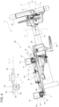
Figures 2 and3 are perspective views of a steering mechanism of the motor vehicle shown inFigure 1 in a first and in a second operating position, respectively; -
Figure 4 is a side view of the steering mechanism shown inFigures 2 and3 ; and -
Figure 5 is a functional diagram of some components of the motor vehicle shown inFigures 1 to 4 . - With reference to
Figure 1 , the numeral 1 indicates a motor vehicle comprising a body 2 defining apassenger compartment 3. - It should be specified that, below in this description, expressions such as "above", "below", "in front of", "behind" and the like are used with reference to the normal driving direction of the motor vehicle 1.
- The motor vehicle 1 further comprises (
Figure 5 ): - one pair of front wheels 6 and one pair of
rear wheels 7; - an
engine 9 of a known type, not shown in detail and operatively connected to the wheels 6 and/or 7 to exert a driving torque on the wheels 6 and/or 7; - a
gearbox 20 interposed between theengine 9 and the wheels 6 and/or 7, which can be operated to vary the transmission ratio between an output member of theengine 9 and thewheels 6, 7; and - a
braking system 21 which can be operated to exert a braking torque on thewheels 6, 7. - The motor vehicle 1 further comprises (
Figure 1 ): - a
windscreen 5 delimiting thepassenger compartment 3 at the front; - a backrest (not shown) delimiting the
passenger compartment 3 at the rear; - a
roof 26 delimiting thepassenger compartment 3 at the top; and - a pair of
doors 8a, 8b hinged to the body 2 and movable between a closed position, wherein they delimit thepassenger compartment 3 at the sides and prevent entry into/exit from thepassenger compartment 3, and an open position, wherein they allow entry into/exit from thepassenger compartment 3. - It is also possible to define:
- a longitudinal axis X integral with the motor vehicle 1, arranged, in use, horizontal and parallel to a normal driving direction of the motor vehicle 1;
- a transversal axis Y integral with the motor vehicle 1, arranged, in use, horizontal and orthogonal to the axis X; and
- an axis Z integral with the motor vehicle 1, arranged, in use, vertical and orthogonal to the axes X, Y.
- The body 2 also comprises a pair of longitudinal,
end door sills passenger compartment 3 and are adjacent torespective doors 8a, 8b when thedoors 8a, 8b are in their closed positions. - In addition, the motor vehicle 1 comprises
control members 10 which can be operated by the driver to set a forward trajectory of the motor vehicle 1 at a desired speed. As is well known, thecontrol members 10 comprise: - a
steering mechanism 11 arranged inside thepassenger compartment 3 and operable by the driver; and - a set of pedals 12 (only schematically shown in
Figure 5 ) also arranged inside thepassenger compartment 3 and operable by the driver. - The set of
pedals 12 comprises, in a nutshell and in a manner not described in detail as it is not necessary for the purpose of the present invention and only schematically illustrated inFigure 5 : - an
accelerator pedal 17 protruding outwards from the base 13 and operable from a released position to a full stroke position in order to adjust the value of the driving torque generated by theengine 9; and - a
brake pedal 18 also protruding from the base 13 and operable to exert an adjustable braking torque value generated by thebraking system 21 on the wheels 6 and/or 7. - If the
engine 9 is an electric engine, thegearbox 20 and the clutch pedal are not present. - If the
gearbox 20 is semi-automatic or automatic, the clutch pedal is not present. - The
control members 10 are connected to the engine and wheels 6 and/or 7 through a drive-by-wire mode, thus producing a technology known in the industry as 'drive by wire' . - The term `drive by wire' in the present description is intended to mean that the
steering mechanism 11 has no physical or mechanical connection to thewheels 6, 7. - Similarly, the
accelerator pedal 17 has no physical or mechanical connection to theengine 9, and thebrake pedal 17 has no mechanical connection to thebraking system 21. - The
passenger compartment 3 further comprises afront location 25 which defines a driver's seat. - The
location 25 is only schematically shown inFigure 1 . - The
passenger compartment 3 of the motor vehicle 1 is selectively movable, in a manner not described in detail because it is not necessary for the understanding of the present invention, between: - a 'two-seater' configuration, in which the
location 25 defines a first seat for a driver and a second seat for a passenger arranged side-by-side along the axis Y; and - a 'single-seater' configuration, in which the
location 25 defines a single third seat for the driver. - In the 'two-seater' configuration, the first seat is beside the
door sill 23, and the second seat is beside thedoor sill 24. - In addition, the first seat faces the
steering mechanism 11 and the set ofpedals 12 to allow the driver to operate thesteering mechanism 11 and the set ofpedals 12. - In the 'single-seater' configuration, the third seat is arranged in a central position between the
door sills steering mechanism 11 and the set ofpedals 12. - The
steering mechanism 11, in turn, comprises (Figures 2 to 4 ): - a
support body 60 fixed to the body 2; - a steering
shaft 61 mounted so that it can rotate around an axis H within thesupport body 60; and - a
steering wheel 62 which can be gripped by the driver to rotate the steeringshaft 61 around the axis H by an angle associated with a desired steering angle of thewheels 6, 7. - The motor vehicle 1 also comprises a control unit 45 (
Figure 5 ) programmed to receive, as input, the operations requested from thesteering mechanism 11 and set ofpedals 12 and to generate, as output, appropriate control signals for theengine 9,gearbox 20,braking system 21 andwheels 6, 7. - In particular, the
control unit 45 is programmed to control the rotation of thewheels 6, 7 by an angle associated with the angle of rotation of thesteering wheel 62 around the axis H and in the same direction of rotation. - In the case illustrated herein, the axis H is inclined with respect to the horizontal plane defined by the axes X, Y by an angle α (
Figure 4 ). - The
steering mechanism 11 also comprises alever 65 that can be selectively moved between: - a locking position, in which it fixedly constrains the steering
shaft 61 to thesupport body 60; and - an adjustment position, in which it allows the steering
shaft 61 to slide relative to thesupport body 60 along the axis H and the consequent adjustment of the position of thesteering wheel 62 relative to the body 2 along the axis H, and the rotation of a centre O of thesteering wheel 62 along an arc of a circle lying in the plane defined by the axes X, Z and the consequent adjustment of the angle α defined between the axes X, H. - Advantageously, the
steering mechanism 11 can be moved along the axis Y to allow the motor vehicle 1 to be moved between the first and the second configuration. - In this way, the
steering mechanism 11 can be moved parallel to the axis Y between: - a first position (
Figure 2 ) taken on when thepassenger compartment 3 is in the first configuration and thesteering wheel 62 faces the first seat defined by thelocation 25; and - a second position (
Figure 3 ) taken on when thepassenger compartment 3 is in the second configuration and thesteering wheel 62 faces the third seat defined by thelocation 25. - The
steering mechanism 11 is adjacent to thedoor sill 23 when it is arranged in the first position (Figure 2 ). In this first position, a first distance between thesteering wheel 62 and thedoor sill 23 is smaller than a second distance between thesteering wheel 62 and thedoor sill 24. Said first and second distances are measured along the axis Y. - A left-hand driving mode of the motor vehicle 1 is thus achieved.
- In greater detail, the
steering wheel 62 is in a central position between thedoor sills steering mechanism 12 is in the second position (Figure 3 ). In this second position, thesteering wheel 62 is equally spaced apart from thedoor sills - With reference to
Figures 2 to 4 , the body 2 also comprises a pair ofcross members - The
cross member 50 is arranged in front of thecross member 51. - The
cross members - respective first ends adjacent to the
door sill 23 of the body 2; and - respective second ends adjacent to the
door sill 24 of the body 2. - The
cross members - respective box-shaped
support bodies - respective
hollow elements corresponding support bodies corresponding seats respective slides - In addition, the
passenger compartment 3 comprises a connection assembly 30 (Figures 2 to 4 ) interposed between the steering mechanism 1 and the body 2 and designed to enable the translation of thesteering mechanism 12 parallel to the axis Y between the first and the second position. - The
connection assembly 30, in turn, comprises: - a pair of
guides bodies respective cross members - a pair of
slides respective guides - an
electric motor 55 operatively connected to theslides transmission assembly 56 and operable to convert the rotation of a pair ofoutput shafts electric motor 55 around a common axis I into the sliding of theslides relevant guides steering mechanism 11 between the first and the second position. - The
slide 76, in particular, is arranged in front of theslide 77. - The
guides slides top face 54 of thesupport body 60. - The
guides related slides corresponding cross members - In particular, the
guides respective seats corresponding cross members - The
guides respective seats cross members - respective first ends adjacent to the
door sill 23 of the body 2; and - respective second ends equally spaced apart between the
door sills - The axis I is parallel to the axis H.
- With reference to
Figure 4 , thetransmission assembly 56, in turn, comprises: - a pair of
flexible shafts respective output shafts electric motor 55 around the axis I; - a pair of
connection elements 90, each functionally interposed between aflexible shaft respective slide flexible shaft 80 into the translation in a first (second) direction of therespective slide - Each
connection element 90 comprises, in particular (Figure 4 ): - a related
helical gear wheel 92, keyed to the respectiveflexible shaft flexible shaft respective seat 89 engaged by theflexible shaft - a
related rack 94 carried by therespective slide respective gear wheel 92 in a radially external position with respect to therelated seat 89. - The motor vehicle 1 further comprises a system for moving the set of
pedals 12 parallel to the axis Y, which is not described in detail as it is not part of the present invention. - In a nutshell, the above-mentioned movement system is operable to cause the movement of the set of
pedals 12 parallel to the axis Y between: - a third position taken on when the
passenger compartment 3 is in the first configuration and thesteering mechanism 11 is in the first position and faces the first seat defined by thelocation 25; and - a fourth position taken on when the
passenger compartment 3 is in the second configuration and thesteering mechanism 11 is in the second position and faces the third seat defined by thelocation 25. - The set of
pedals 12 is adjacent to thedoor sill 23 when it is in the third position. - The set of
pedals 12 is in a central position between thedoor sills - The operation of the motor vehicle 1 is described starting from a condition in which the
passenger compartment 3 is in the 'two-seater' configuration. - The operation of the motor vehicle 1 is also described starting from a condition in which the
lever 65 is in the locking position. - In this 'two-seater' configuration, the
location 25 defines the first seat for the driver and the second seat for a passenger arranged side-by-side parallel to the axis Y. - More precisely, the first seat is beside the
door sill 23, and the second seat is beside thedoor sill 24 parallel to the axis Y. - As shown in
Figures 1 and2 , thesteering mechanism 11 and the set of pedals 12 (not shown in the aforementionedFigures 1 and2 ) are also arranged in the first and the third position, respectively, in which they face the first seat defined by thelocation 25 along the axis X. - In addition, the first seat faces the
steering mechanism 11 and the set ofpedals 12 along the axis X to allow the driver to operate thesteering mechanism 11 and the set ofpedals 12 and thus control the forward trajectory and the speed of the motor vehicle 1. - If it is desired to reconfigure the motor vehicle 1 so as to arrange the
passenger compartment 3 into the 'single-seater' configuration, it is sufficient to operate theelectric motor 55 in a first direction via a dedicated control and under certain operating conditions of the motor vehicle 1. - The operation of the
electric motor 55 in the first direction causes theoutput shafts flexible shafts - These rotations of the
flexible shafts respective connection elements 90, the translation of theslides steering mechanism 11 in the first direction along the axis Y in relation to the body 2. - More specifically, the rotations of the
flexible shafts respective gear wheels 92 around the axis I, and the translation of therespective racks 94 and slides 76, 77 parallel to the respective axes J. - Since the transmission of motion between the
gear wheels 92 and therespective racks 94 is irreversible, theslides electric motor 55. - As a result, the
steering mechanism 11 reaches the second position shown inFigure 3 in which it faces the third seat defined by the driving position. - More precisely, the
steering mechanism 11 is in a central position between thedoor sills - The system for moving the
steering mechanism 11 is operated to cause the movement of the set ofpedals 12 parallel to the axis Y until it reaches the fourth position. - The set of
pedals 12 is in a central position between thedoor sills location 25 when it is in the fourth position. - The
location 25 is reconfigured so as to only define the third seat for the driver, which is not necessary for the understanding of the present invention. - The single third seat is arranged in a central position between the
door sills steering mechanism 11 and the set ofpedals 12. - At this point, the
passenger compartment 3 has taken on the 'single-seater' configuration. - The
passenger compartment 3 is repositioned from the 'single-seater' configuration to the 'two-seater' configuration by simply operating theelectric motor 55 in a second direction opposite the first direction, so as to return thesteering mechanism 11 to the first position. - Subsequently or simultaneously, the set of
pedals 12 is arranged into the third position and thelocation 25 is reconfigured to define the first seat for the driver and the second seat. - Both when the
passenger compartment 3 is in the 'two-seater' configuration and when thepassenger compartment 3 is in the 'single-seater' configuration, the position of thesteering wheel 62 in relation to the body 2 along the axis H and the value of the angle α can be adjusted simply by moving thelever 65 into the unlocking position and moving the steeringshaft 61 andsteering wheel 62 in relation to thesupport body 60 and then arranging thelever 65 into the locking position once the above adjustment is complete. - The advantages enabled by the present invention will be apparent from an examination thereof.
- In greater detail, the
steering mechanism 11 can be moved along the axis Y between the first and the second position, so that thepassenger compartment 3 can be moved between the 'two-seater' configuration and the `single-seater' configuration. - In fact, the
steering wheel 62 in the first position of thesteering mechanism 11 faces, along the axis X, the first seat for the driver defined by thelocation 25 adjacent to thedoor sill 23. - Similarly, the
steering wheel 62 in the second position of thesteering mechanism 11 faces, along the axis X, the single third seat for the driver defined by thelocation 25 in a central position between thedoor sills - The
electric motor 55 and thetransmission assembly 56 formed by theflexible shafts respective connection elements 90 ensure a fast and precise movement of thesteering mechanism 11 between the above-mentioned first and second positions. - The
connection elements 90 irreversibly transmit the motion from theelectric motor 55 to therespective slides respective gear wheels 92 and the corresponding racks 94. - This ensures that the
slides electric motor 55. - The fact that the
slides support body 60 of thesteering mechanism 12 allows the position of thesteering wheel 62 along the axis H and the angle α to be adjusted by simply operating thelever 65 both when the motor vehicle 1 is in the 'single-seater' configuration and when the motor vehicle 1 is in the 'two-seater' configuration. - Lastly, it is clear that modifications and variations may be made to the motor vehicle 1 and the reconfiguration method according to the present invention, without however departing from the scope of protection defined by the claims.
- In particular, in the 'two-seater' configuration, the first seat could be positioned facing the
door sill 24 and the second seat could be positioned facing thedoor sill 24, thus achieving a right-hand driving mode of the motor vehicle 1.
Claims (12)
- A motor vehicle (1) comprising:- a passenger compartment (3);- at least one pair of wheels (6; 7); and- a steering mechanism (11), which can be operated by a driver in order to adjust a steering angle of at least two (6) of said wheels (6, 7);said steering mechanism (11) being connected to said wheels (6; 7) through a drive by wire mode;said motor vehicle (1) being selectively available in:- a first configuration, wherein said passenger compartment (3) defines a first seat for a driver facing said steering mechanism (11) and a second seat for a passenger beside said first seat along a first axis (Y); and- a second configuration, wherein said passenger compartment (3) only defines a third seat for said driver;said first seat being arranged in a first position and said second seat being arranged in a second position in said first configuration, and said third seat being arranged, in said second configuration, in a third position spaced apart from said first position along said first axis (Y);characterized by the fact that said steering mechanism (11) can be moved along said first axis (Y) between a fourth position taken on when said motor vehicle (1) is in said first configuration and a fifth position taken on when said motor vehicle (2) is in said second configuration; said third and fourth positions being spaced apart from one another along said first axis (Y).
- The motor vehicle according to claim 1, characterized by the fact that it comprises:- a set (12) of pedals comprising, in turn, a first accelerator pedal (17) and a second brake pedal (18);- an engine (9); and- a braking system (21);said first accelerator pedal (17) being capable of being operated by said driver in order to adjust the torque delivered by said engine (9) and being operatively connected to said wheels (6; 7) through a drive by wire mode;said second brake pedal (18) being capable of being operated by said driver in order to exert a braking torque upon at least one of said wheels (6; 7) and being operatively connected to said wheels (6; 7) through a drive by wire mode;said set (12) of pedals being capable of moving along said first axis (Y) between:- a sixth position taken on when said motor vehicle (1) is, in use, in said first configuration; and- a seventh position taken on when said motor vehicle (1) is, in use, in said second configuration;said sixth and seventh positions being spaced apart from one another along said first axis (Y);said set (12) of pedals being movable between said sixth and seventh positions independently of the movement, in use, of said steering mechanisms (11) between said first and second positions.
- The motor vehicle according to claim 1 or 2, characterized by the fact that it comprises:- a body (2);- a first guide (52; 53) fixed to said body (2);- a first slide (76; 77) fixed to said steering mechanism (11) and coupled to said first guide (52; 53) so as to slide parallel to said first axis (Y); and- a motor member (55) fixed to said body (2) and capable of being selectively operated in order to cause the translation of said first slide (76, 77) on said first guide (52; 53) parallel to said first axis (Y).
- The motor vehicle according to claim 3, characterized by the fact that it comprises:- a second guide (53; 52) fixed to said body (2) in a position spaced apart from said first guide (50; 51) along a second axis (X), which is orthogonal to said first axis (Y) and parallel to a normal longitudinal driving direction of said motor vehicle (1); and- a second slide (77; 76) fixed to said steering mechanism (12) in a position spaced apart from said first slide (76, 77) along said second axis (X);said motor member (55) being operatively connected to said first and second slides (76, 77) in order to cause the translation of said first and second slides (76, 77) relative to said respective first and second guides (52, 53) parallel to said first axis (Y).
- The motor vehicle according to claim 4, characterized by the fact that it comprises a transmission assembly (56) interposed between said motor member (55) and said first and second slides (76; 77);
said transmission assembly (56) being configured to irreversibly transmit, in use, a motion from said motor member (55) to said first and second slides (76; 77). - The motor vehicle according to claim 5, characterized by the fact that said transmission assembly (56) comprises, in turn:- a first flexible shaft (80) operated by said motor (55) and operatively connected to said first slide (76; 77);- a second flexible shaft (81) operated by said motor (55) and operatively connected to said second slide (77; 76) ;- a first connection element (90) interposed between said first flexible shaft (80) and said first slide (76; 77) and configured to convert the rotation of said first flexible shaft (80) in a first direction into the translation of said first slide (76; 77) along said first axis (Y) in a second direction; and- a second connection element (90) interposed between said second flexible shaft (81) and said second slide (77; 76) and configured to convert the rotation of said second flexible shaft (81) in said first direction into the translation of said first slide (76; 77) parallel to said first axis (Y) in said second direction.
- The motor vehicle according to any one of the claims from 3 to 6, characterized by the fact that said motor member (55) is an electric motor member.
- The motor vehicle according to any one of the preceding claims, characterized by the fact that said body (2) comprises a first door sill (23) and a second door sill (24) extending along said second axis (X);said first door sill (23) and said second door sill (24) being spaced apart from one another along said first axis (Y);said steering mechanism (11) being arranged, in said first position, adjacent to said first door sill (23) and at a first distance from said first door sill (23) which is smaller than a second distance from said second door sill (24), when said motor vehicle (1) is in said first configuration; said first and second distances being measured along said first axis (Y);said steering mechanism (11) being arranged, in said second position, in a position equally spaced apart from said first and second door sills (23, 24) along said first axis (Y), when said motor vehicle (1) is in said second configuration.
- The motor vehicle according to any one of the claims from 3 to 8, characterized by the fact that said steering mechanism (11) comprises:- a steering wheel (62), which can be operated by a driver;- a support body (60) designed to support said steering wheel (62) and fixed to said first slide (76,77); and- a steering shaft (61) fixed to said steering wheel (62) and mounted in a telescopic manner inside said support body (60) along a third axis (H), which is orthogonal to said first axis (Y);the position of said steering shaft (61) relative to said support body (60) along said third axis (H) and/or an angle (α) defined between said third axis (H) and said second axis (X) being adjustable.
- A method for the reconfiguration of a passenger compartment (3) of a motor vehicle (1);said motor vehicle (1) comprising:- a passenger compartment (3);- at least one pair of wheels (6; 7);- a steering mechanism (11), which can be operated by a driver in order to adjust a steering angle of at least two (6) of said wheels (6, 7);said steering mechanism (11) being connected to said wheels (6; 7) through a drive by wire mode;said motor vehicle (1) being selectively available in:- a first configuration, wherein said passenger compartment (3) defines a first seat for a driver facing said steering mechanism (11) and a second seat for a passenger beside said first seat along a first axis (Y); and- a second configuration, wherein said passenger compartment (3) only defines a third seat for said driver;said first seat being arranged in a first position and said second seat being arranged in a second position in said first configuration, and said third seat being arranged, in said second configuration, in a third position spaced apart from said first position along said first axis (Y);characterized by the fact that said step i) comprises the step ii) of moving said steering mechanism (11) along said first axis (Y) between:- a fourth position taken on when said motor vehicle (1) is in said first configuration; and- a fifth position taken on when said motor vehicle (1) is in said second configuration;said fourth and fifth positions being spaced apart from one another along said first axis (Y).
- The configuration method according to claim 10, characterized by the fact that said step ii) comprises the steps of:iii) shifting said steering mechanism (11) to said fourth position, in a position adjacent to a first door sill (23) of said body (2) and at a first distance from said first door sill (23) which is smaller than a second distance from a second door sill (24) of said body (2); said first and second distances being measured along said first axis (Y); andiv) shifting said steering mechanism (11) to said fifth position, in a position equally spaced apart from said first and second door sills (23, 24) along said first axis (Y);said first door sill (23) and said second door sill (24) extending along a second axis (X), which is parallel, in use, to a normal driving direction of said motor vehicle and is transversal to said first axis (Y); said first door sill (23) and said second door sill (24) being spaced apart from one another along said first axis (Y).
- The method according to claim 10 or 11, characterized by the fact that it comprises the step v) of moving a set (12) of pedals along said first axis (Y) between:- a sixth position taken on when said motor vehicle (1) is in said first configuration; and- a seventh position taken on when said motor vehicle (2) is in said second configuration;said sixth and seventh positions being spaced apart from one another along said first axis (Y);said step ii) being carried out independently of said step v).
Applications Claiming Priority (1)
| Application Number | Priority Date | Filing Date | Title |
|---|---|---|---|
| IT102023000003852A IT202300003852A1 (en) | 2023-03-03 | 2023-03-03 | MOTOR VEHICLE AND METHOD OF RECONFIGURATION OF THE MOTOR VEHICLE ITSELF |
Publications (2)
| Publication Number | Publication Date |
|---|---|
| EP4424566A1 true EP4424566A1 (en) | 2024-09-04 |
| EP4424566B1 EP4424566B1 (en) | 2026-04-08 |
Family
ID=86469292
Family Applications (1)
| Application Number | Title | Priority Date | Filing Date |
|---|---|---|---|
| EP24160437.0A Active EP4424566B1 (en) | 2023-03-03 | 2024-02-29 | Motor vehicle and method for the reconfiguration of the motor vehicle |
Country Status (4)
| Country | Link |
|---|---|
| US (1) | US12221152B2 (en) |
| EP (1) | EP4424566B1 (en) |
| CN (1) | CN118579131A (en) |
| IT (1) | IT202300003852A1 (en) |
Families Citing this family (2)
| Publication number | Priority date | Publication date | Assignee | Title |
|---|---|---|---|---|
| US20250276731A1 (en) * | 2024-03-01 | 2025-09-04 | Ferrari S.P.A. | Steering system for motor vehicle and motor vehicle comprising the same |
| US12583507B1 (en) * | 2024-11-21 | 2026-03-24 | Fca Us Llc | Decoupled driver controls module for vehicle |
Citations (6)
| Publication number | Priority date | Publication date | Assignee | Title |
|---|---|---|---|---|
| US5218920A (en) * | 1988-12-28 | 1993-06-15 | Yamaha Hatsudoki Kabushiki Kaisha | Steering arrangement for small watercraft |
| CN107521548A (en) * | 2017-09-28 | 2017-12-29 | 鄂尔多斯市普渡科技有限公司 | A kind of movable direction disk of vehicle |
| US20200254906A1 (en) * | 2019-02-11 | 2020-08-13 | Byton North America Corporation | Sliding center module system for vehicle |
| EP3712035A2 (en) | 2019-03-20 | 2020-09-23 | Volvo Car Corporation | Vehicle having multiple driving positions |
| US20210078625A1 (en) * | 2019-09-17 | 2021-03-18 | Honda Motor Co., Ltd. | Vehicle control system |
| GB2598584A (en) * | 2020-09-02 | 2022-03-09 | Jaguar Land Rover Ltd | Adjustable user input system |
Family Cites Families (7)
| Publication number | Priority date | Publication date | Assignee | Title |
|---|---|---|---|---|
| US6991060B2 (en) * | 2001-12-13 | 2006-01-31 | General Motors Corporation | Vehicle having a movable driving position |
| US6857498B2 (en) * | 2002-07-25 | 2005-02-22 | General Motors Corporation | Console with driver's interface |
| US7363131B2 (en) * | 2004-06-16 | 2008-04-22 | Chrysler Llc | Re-positionable vehicle control-by-wire assembly, method, and system |
| US7490694B1 (en) * | 2005-08-04 | 2009-02-17 | Polaris Industries Inc. | Steering conversion vehicle |
| JP6304162B2 (en) * | 2015-07-27 | 2018-04-04 | トヨタ自動車株式会社 | Vehicle seat control device |
| JP7140697B2 (en) * | 2019-03-04 | 2022-09-21 | 本田技研工業株式会社 | vehicle steering system |
| JP7517159B2 (en) * | 2021-01-13 | 2024-07-17 | トヨタ自動車株式会社 | Vehicle seat device |
-
2023
- 2023-03-03 IT IT102023000003852A patent/IT202300003852A1/en unknown
-
2024
- 2024-02-29 US US18/591,484 patent/US12221152B2/en active Active
- 2024-02-29 EP EP24160437.0A patent/EP4424566B1/en active Active
- 2024-03-04 CN CN202410244441.XA patent/CN118579131A/en active Pending
Patent Citations (6)
| Publication number | Priority date | Publication date | Assignee | Title |
|---|---|---|---|---|
| US5218920A (en) * | 1988-12-28 | 1993-06-15 | Yamaha Hatsudoki Kabushiki Kaisha | Steering arrangement for small watercraft |
| CN107521548A (en) * | 2017-09-28 | 2017-12-29 | 鄂尔多斯市普渡科技有限公司 | A kind of movable direction disk of vehicle |
| US20200254906A1 (en) * | 2019-02-11 | 2020-08-13 | Byton North America Corporation | Sliding center module system for vehicle |
| EP3712035A2 (en) | 2019-03-20 | 2020-09-23 | Volvo Car Corporation | Vehicle having multiple driving positions |
| US20210078625A1 (en) * | 2019-09-17 | 2021-03-18 | Honda Motor Co., Ltd. | Vehicle control system |
| GB2598584A (en) * | 2020-09-02 | 2022-03-09 | Jaguar Land Rover Ltd | Adjustable user input system |
Also Published As
| Publication number | Publication date |
|---|---|
| IT202300003852A1 (en) | 2024-09-03 |
| US12221152B2 (en) | 2025-02-11 |
| US20240294205A1 (en) | 2024-09-05 |
| EP4424566B1 (en) | 2026-04-08 |
| CN118579131A (en) | 2024-09-03 |
Similar Documents
| Publication | Publication Date | Title |
|---|---|---|
| EP4424566B1 (en) | Motor vehicle and method for the reconfiguration of the motor vehicle | |
| US11414057B2 (en) | Retractable pedal assembly for a vehicle | |
| US10081272B2 (en) | Method of positioning a vehicle seat | |
| US20130233638A1 (en) | Electric power steering apparatus for vehicle | |
| EP3877237B1 (en) | Manual steering control unit for autonomous vehicle | |
| JP5303570B2 (en) | Operating device with lock roller | |
| DE102019112875A1 (en) | Steering system of a vehicle and method for operating a steering system of a vehicle | |
| WO2018108943A1 (en) | Vehicle including control pedal arrangement | |
| EP4424567A1 (en) | Motor vehicle and method for the reconfiguration of a passenger compartment of the motor vehicle | |
| DE102015225522A1 (en) | Arrangement for a steer-by-wire steering | |
| CN115723533A (en) | Rod movable across vehicle door opening | |
| GB1565505A (en) | Adjustable pedal assembly for a vehicle | |
| US20030126941A1 (en) | Clutch pedal designed to equip a motor vehicle | |
| GB2598584A (en) | Adjustable user input system | |
| US20240092309A1 (en) | Vehicle seat buckle assembly | |
| EP0943472A2 (en) | Passenger vehicle | |
| US20250276731A1 (en) | Steering system for motor vehicle and motor vehicle comprising the same | |
| EP4516542A1 (en) | Car provided with an air conditioning system arranged behind the passenger compartment | |
| US6848545B2 (en) | Brake actuation assembly for a vehicle | |
| EP4494933A1 (en) | Cockpit for a motor vehicle and method for the reconfiguration of a cockpit | |
| EP4494931A1 (en) | Cockpit for a motor vehicle and method for the reconfiguration of a cockpit | |
| EP4494932A1 (en) | Cockpit for a motor vehicle and method for the reconfiguration of a cockpit | |
| DE19621023C1 (en) | Control lever for automobile steering control | |
| US20030146040A1 (en) | Dual-mode drive-by-wire steering system | |
| EP4494930A1 (en) | Cockpit for a motor vehicle and method for the reconfiguration of a cockpit |
Legal Events
| Date | Code | Title | Description |
|---|---|---|---|
| PUAI | Public reference made under article 153(3) epc to a published international application that has entered the european phase |
Free format text: ORIGINAL CODE: 0009012 |
|
| STAA | Information on the status of an ep patent application or granted ep patent |
Free format text: STATUS: THE APPLICATION HAS BEEN PUBLISHED |
|
| AK | Designated contracting states |
Kind code of ref document: A1 Designated state(s): AL AT BE BG CH CY CZ DE DK EE ES FI FR GB GR HR HU IE IS IT LI LT LU LV MC ME MK MT NL NO PL PT RO RS SE SI SK SM TR |
|
| STAA | Information on the status of an ep patent application or granted ep patent |
Free format text: STATUS: REQUEST FOR EXAMINATION WAS MADE |
|
| 17P | Request for examination filed |
Effective date: 20250121 |
|
| GRAP | Despatch of communication of intention to grant a patent |
Free format text: ORIGINAL CODE: EPIDOSNIGR1 |
|
| STAA | Information on the status of an ep patent application or granted ep patent |
Free format text: STATUS: GRANT OF PATENT IS INTENDED |
|
| INTG | Intention to grant announced |
Effective date: 20251105 |
|
| RIN1 | Information on inventor provided before grant (corrected) |
Inventor name: CONIGLIARO, VITO Inventor name: ANNEQUIN-DIGOND, THIERRY |
|
| GRAS | Grant fee paid |
Free format text: ORIGINAL CODE: EPIDOSNIGR3 |
|
| GRAA | (expected) grant |
Free format text: ORIGINAL CODE: 0009210 |
|
| STAA | Information on the status of an ep patent application or granted ep patent |
Free format text: STATUS: THE PATENT HAS BEEN GRANTED |
|
| AK | Designated contracting states |
Kind code of ref document: B1 Designated state(s): AL AT BE BG CH CY CZ DE DK EE ES FI FR GB GR HR HU IE IS IT LI LT LU LV MC ME MK MT NL NO PL PT RO RS SE SI SK SM TR |
|
| REG | Reference to a national code |
Ref country code: CH Ref legal event code: F10 Free format text: ST27 STATUS EVENT CODE: U-0-0-F10-F00 (AS PROVIDED BY THE NATIONAL OFFICE) Effective date: 20260408 Ref country code: GB Ref legal event code: FG4D |
|
| REG | Reference to a national code |
Ref country code: DE Ref legal event code: R096 Ref document number: 602024003723 Country of ref document: DE |