EP4424564A1 - Method and device for controlling power through consideration of transient characteristics of hybrid vehicle - Google Patents
Method and device for controlling power through consideration of transient characteristics of hybrid vehicle Download PDFInfo
- Publication number
- EP4424564A1 EP4424564A1 EP22887650.4A EP22887650A EP4424564A1 EP 4424564 A1 EP4424564 A1 EP 4424564A1 EP 22887650 A EP22887650 A EP 22887650A EP 4424564 A1 EP4424564 A1 EP 4424564A1
- Authority
- EP
- European Patent Office
- Prior art keywords
- power
- fuel
- power output
- battery
- command
- Prior art date
- Legal status (The legal status is an assumption and is not a legal conclusion. Google has not performed a legal analysis and makes no representation as to the accuracy of the status listed.)
- Pending
Links
Images







Classifications
-
- B—PERFORMING OPERATIONS; TRANSPORTING
- B60—VEHICLES IN GENERAL
- B60W—CONJOINT CONTROL OF VEHICLE SUB-UNITS OF DIFFERENT TYPE OR DIFFERENT FUNCTION; CONTROL SYSTEMS SPECIALLY ADAPTED FOR HYBRID VEHICLES; ROAD VEHICLE DRIVE CONTROL SYSTEMS FOR PURPOSES NOT RELATED TO THE CONTROL OF A PARTICULAR SUB-UNIT
- B60W20/00—Control systems specially adapted for hybrid vehicles
- B60W20/10—Controlling the power contribution of each of the prime movers to meet required power demand
- B60W20/13—Controlling the power contribution of each of the prime movers to meet required power demand in order to stay within battery power input or output limits; in order to prevent overcharging or battery depletion
-
- B—PERFORMING OPERATIONS; TRANSPORTING
- B60—VEHICLES IN GENERAL
- B60W—CONJOINT CONTROL OF VEHICLE SUB-UNITS OF DIFFERENT TYPE OR DIFFERENT FUNCTION; CONTROL SYSTEMS SPECIALLY ADAPTED FOR HYBRID VEHICLES; ROAD VEHICLE DRIVE CONTROL SYSTEMS FOR PURPOSES NOT RELATED TO THE CONTROL OF A PARTICULAR SUB-UNIT
- B60W10/00—Conjoint control of vehicle sub-units of different type or different function
- B60W10/04—Conjoint control of vehicle sub-units of different type or different function including control of propulsion units
- B60W10/06—Conjoint control of vehicle sub-units of different type or different function including control of propulsion units including control of combustion engines
-
- B—PERFORMING OPERATIONS; TRANSPORTING
- B60—VEHICLES IN GENERAL
- B60W—CONJOINT CONTROL OF VEHICLE SUB-UNITS OF DIFFERENT TYPE OR DIFFERENT FUNCTION; CONTROL SYSTEMS SPECIALLY ADAPTED FOR HYBRID VEHICLES; ROAD VEHICLE DRIVE CONTROL SYSTEMS FOR PURPOSES NOT RELATED TO THE CONTROL OF A PARTICULAR SUB-UNIT
- B60W10/00—Conjoint control of vehicle sub-units of different type or different function
- B60W10/04—Conjoint control of vehicle sub-units of different type or different function including control of propulsion units
- B60W10/08—Conjoint control of vehicle sub-units of different type or different function including control of propulsion units including control of electric propulsion units, e.g. motors or generators
-
- B—PERFORMING OPERATIONS; TRANSPORTING
- B60—VEHICLES IN GENERAL
- B60W—CONJOINT CONTROL OF VEHICLE SUB-UNITS OF DIFFERENT TYPE OR DIFFERENT FUNCTION; CONTROL SYSTEMS SPECIALLY ADAPTED FOR HYBRID VEHICLES; ROAD VEHICLE DRIVE CONTROL SYSTEMS FOR PURPOSES NOT RELATED TO THE CONTROL OF A PARTICULAR SUB-UNIT
- B60W10/00—Conjoint control of vehicle sub-units of different type or different function
- B60W10/24—Conjoint control of vehicle sub-units of different type or different function including control of energy storage means
- B60W10/26—Conjoint control of vehicle sub-units of different type or different function including control of energy storage means for electrical energy, e.g. batteries or capacitors
-
- B—PERFORMING OPERATIONS; TRANSPORTING
- B60—VEHICLES IN GENERAL
- B60W—CONJOINT CONTROL OF VEHICLE SUB-UNITS OF DIFFERENT TYPE OR DIFFERENT FUNCTION; CONTROL SYSTEMS SPECIALLY ADAPTED FOR HYBRID VEHICLES; ROAD VEHICLE DRIVE CONTROL SYSTEMS FOR PURPOSES NOT RELATED TO THE CONTROL OF A PARTICULAR SUB-UNIT
- B60W20/00—Control systems specially adapted for hybrid vehicles
-
- B—PERFORMING OPERATIONS; TRANSPORTING
- B60—VEHICLES IN GENERAL
- B60W—CONJOINT CONTROL OF VEHICLE SUB-UNITS OF DIFFERENT TYPE OR DIFFERENT FUNCTION; CONTROL SYSTEMS SPECIALLY ADAPTED FOR HYBRID VEHICLES; ROAD VEHICLE DRIVE CONTROL SYSTEMS FOR PURPOSES NOT RELATED TO THE CONTROL OF A PARTICULAR SUB-UNIT
- B60W20/00—Control systems specially adapted for hybrid vehicles
- B60W20/10—Controlling the power contribution of each of the prime movers to meet required power demand
- B60W20/11—Controlling the power contribution of each of the prime movers to meet required power demand using model predictive control [MPC] strategies, i.e. control methods based on models predicting performance
-
- B—PERFORMING OPERATIONS; TRANSPORTING
- B60—VEHICLES IN GENERAL
- B60W—CONJOINT CONTROL OF VEHICLE SUB-UNITS OF DIFFERENT TYPE OR DIFFERENT FUNCTION; CONTROL SYSTEMS SPECIALLY ADAPTED FOR HYBRID VEHICLES; ROAD VEHICLE DRIVE CONTROL SYSTEMS FOR PURPOSES NOT RELATED TO THE CONTROL OF A PARTICULAR SUB-UNIT
- B60W20/00—Control systems specially adapted for hybrid vehicles
- B60W20/10—Controlling the power contribution of each of the prime movers to meet required power demand
- B60W20/15—Control strategies specially adapted for achieving a particular effect
-
- B—PERFORMING OPERATIONS; TRANSPORTING
- B60—VEHICLES IN GENERAL
- B60W—CONJOINT CONTROL OF VEHICLE SUB-UNITS OF DIFFERENT TYPE OR DIFFERENT FUNCTION; CONTROL SYSTEMS SPECIALLY ADAPTED FOR HYBRID VEHICLES; ROAD VEHICLE DRIVE CONTROL SYSTEMS FOR PURPOSES NOT RELATED TO THE CONTROL OF A PARTICULAR SUB-UNIT
- B60W20/00—Control systems specially adapted for hybrid vehicles
- B60W20/10—Controlling the power contribution of each of the prime movers to meet required power demand
- B60W20/15—Control strategies specially adapted for achieving a particular effect
- B60W20/16—Control strategies specially adapted for achieving a particular effect for reducing engine exhaust emissions
-
- B—PERFORMING OPERATIONS; TRANSPORTING
- B60—VEHICLES IN GENERAL
- B60W—CONJOINT CONTROL OF VEHICLE SUB-UNITS OF DIFFERENT TYPE OR DIFFERENT FUNCTION; CONTROL SYSTEMS SPECIALLY ADAPTED FOR HYBRID VEHICLES; ROAD VEHICLE DRIVE CONTROL SYSTEMS FOR PURPOSES NOT RELATED TO THE CONTROL OF A PARTICULAR SUB-UNIT
- B60W50/00—Details of control systems for road vehicle drive control not related to the control of a particular sub-unit, e.g. process diagnostic or vehicle driver interfaces
-
- B—PERFORMING OPERATIONS; TRANSPORTING
- B60—VEHICLES IN GENERAL
- B60W—CONJOINT CONTROL OF VEHICLE SUB-UNITS OF DIFFERENT TYPE OR DIFFERENT FUNCTION; CONTROL SYSTEMS SPECIALLY ADAPTED FOR HYBRID VEHICLES; ROAD VEHICLE DRIVE CONTROL SYSTEMS FOR PURPOSES NOT RELATED TO THE CONTROL OF A PARTICULAR SUB-UNIT
- B60W50/00—Details of control systems for road vehicle drive control not related to the control of a particular sub-unit, e.g. process diagnostic or vehicle driver interfaces
- B60W2050/0001—Details of the control system
- B60W2050/0019—Control system elements or transfer functions
- B60W2050/0028—Mathematical models, e.g. for simulation
- B60W2050/0037—Mathematical models of vehicle sub-units
-
- B—PERFORMING OPERATIONS; TRANSPORTING
- B60—VEHICLES IN GENERAL
- B60W—CONJOINT CONTROL OF VEHICLE SUB-UNITS OF DIFFERENT TYPE OR DIFFERENT FUNCTION; CONTROL SYSTEMS SPECIALLY ADAPTED FOR HYBRID VEHICLES; ROAD VEHICLE DRIVE CONTROL SYSTEMS FOR PURPOSES NOT RELATED TO THE CONTROL OF A PARTICULAR SUB-UNIT
- B60W2510/00—Input parameters relating to a particular sub-units
- B60W2510/06—Combustion engines, Gas turbines
- B60W2510/0604—Throttle position
-
- B—PERFORMING OPERATIONS; TRANSPORTING
- B60—VEHICLES IN GENERAL
- B60W—CONJOINT CONTROL OF VEHICLE SUB-UNITS OF DIFFERENT TYPE OR DIFFERENT FUNCTION; CONTROL SYSTEMS SPECIALLY ADAPTED FOR HYBRID VEHICLES; ROAD VEHICLE DRIVE CONTROL SYSTEMS FOR PURPOSES NOT RELATED TO THE CONTROL OF A PARTICULAR SUB-UNIT
- B60W2710/00—Output or target parameters relating to a particular sub-units
- B60W2710/06—Combustion engines, Gas turbines
-
- B—PERFORMING OPERATIONS; TRANSPORTING
- B60—VEHICLES IN GENERAL
- B60W—CONJOINT CONTROL OF VEHICLE SUB-UNITS OF DIFFERENT TYPE OR DIFFERENT FUNCTION; CONTROL SYSTEMS SPECIALLY ADAPTED FOR HYBRID VEHICLES; ROAD VEHICLE DRIVE CONTROL SYSTEMS FOR PURPOSES NOT RELATED TO THE CONTROL OF A PARTICULAR SUB-UNIT
- B60W2710/00—Output or target parameters relating to a particular sub-units
- B60W2710/24—Energy storage means
- B60W2710/242—Energy storage means for electrical energy
-
- B—PERFORMING OPERATIONS; TRANSPORTING
- B60—VEHICLES IN GENERAL
- B60Y—INDEXING SCHEME RELATING TO ASPECTS CROSS-CUTTING VEHICLE TECHNOLOGY
- B60Y2200/00—Type of vehicle
- B60Y2200/90—Vehicles comprising electric prime movers
- B60Y2200/91—Electric vehicles
-
- Y—GENERAL TAGGING OF NEW TECHNOLOGICAL DEVELOPMENTS; GENERAL TAGGING OF CROSS-SECTIONAL TECHNOLOGIES SPANNING OVER SEVERAL SECTIONS OF THE IPC; TECHNICAL SUBJECTS COVERED BY FORMER USPC CROSS-REFERENCE ART COLLECTIONS [XRACs] AND DIGESTS
- Y02—TECHNOLOGIES OR APPLICATIONS FOR MITIGATION OR ADAPTATION AGAINST CLIMATE CHANGE
- Y02T—CLIMATE CHANGE MITIGATION TECHNOLOGIES RELATED TO TRANSPORTATION
- Y02T10/00—Road transport of goods or passengers
- Y02T10/60—Other road transportation technologies with climate change mitigation effect
- Y02T10/62—Hybrid vehicles
Definitions
- the present invention relates to a power control method and apparatus that considers the transient characteristics of a hybrid vehicle, and more specifically, to a power control method and apparatus that maximizes the performance of a hybrid vehicle in an actual operating environment by reducing fuel power source transients.
- FIG. 1A is a diagram illustrating an engine fuel consumption map in a hybrid vehicle in a steady state
- FIG. 1B is a diagram illustrating a motor efficiency map in a hybrid vehicle in a steady state
- FIG. 2 is a diagram illustrating a fuel consumption characteristic in a transient state when the fuel source is an engine.
- the fuel power source consumes less fuel per energy at medium to high power range, and the motor is efficient throughout the driving range.
- the fuel power source has different fuel consumption characteristics in the transient state than in the steady state. That is, there is a large difference in fuel consumption amount between the measured value ( ⁇ f ⁇ meas ) and the calculated value of the steady-state fuel map ( ⁇ f ⁇ SS ) during transients such as starting and power changes.
- a power control strategy is needed to solve transient state problems by taking into account the efficiency characteristics of the two power sources.
- the present invention was devised to solve these problems. Its purpose is to provide a method and apparatus that can effectively solve the optimal power control problem without a transient state model of the fuel power source, thereby reducing the transient operation of the fuel power source and maximizing the performance of hybrid vehicles in real-world driving conditions.
- a power control method considering the transient characteristics of a hybrid vehicle, comprising: (a) receiving a current requested power value from the hybrid vehicle; (b) calculating an average requested power from the received plurality of requested power values; (c) calculating an optimal fuel power output command value that minimizes an average equivalent fuel consumption for the average requested power; (d) calculating a battery-based power command from the optimal fuel power output command calculated in step (c) and the requested power value; and (e) transmitting the optimal fuel power output command and the battery-based power command to a control system of the hybrid vehicle.
- the power control method may further comprise between step (c) and step (d), a step of: (c1) determining the fuel power output command as an allowable minimum value of the fuel power output if the fuel power output command value calculated in step (c) is less than or equal to the allowable minimum value of the fuel power output, determining the fuel power output command as an allowable maximum value of the fuel power output if the calculated fuel power output command value is greater than or equal to the allowable maximum value of the fuel power output, and determining the fuel power output command as the calculated fuel power output command value if the calculated fuel power output command value is between the allowable maximum value and the allowable minimum value of the fuel power output.
- the instantaneous fuel amount model equation is and the battery power model equation is where the motor power ( P m ) is determined by the difference between the requested power (P) and the fuel power output ( P f ) , w m is the motor speed, w f is the engine speed, q 0 , q 1 , q 2 are each a function of w f , and r 0 , r 1 , r 2 are each a function of w m .
- the battery-based power command calculated in step (d) is a motor power command.
- the battery-based power command calculated in step (d) is a battery power command.
- an apparatus for performing power control considering the transient characteristics of a hybrid vehicle comprising: at least one processor; and at least one memory storing computer-executable instructions, wherein the computer-executable instructions stored in the at least one memory cause the at least one processor to perform: (a) receiving a current requested power value from the hybrid vehicle; (b) calculating an average requested power from the received plurality of requested power values; (c) calculating an optimal fuel power output command value that minimizes an average equivalent fuel consumption for the average requested power; (d) calculating a battery-based power command from the optimal fuel power output command calculated in step (c) and the requested power value; and (e) transmitting the optimal fuel power output command and the battery-based power command to a control system of the hybrid vehicle.
- a computer program for performing power control considering the transient characteristics of a hybrid vehicle stored on a non-transitory storage medium, and comprising instructions that cause a processor to perform: (a) receiving a current requested power value from the hybrid vehicle; (b) calculating an average requested power from the received plurality of requested power values; (c) calculating an optimal fuel power output command value that minimizes an average equivalent fuel consumption for the average requested power; (d) calculating a battery-based power command from the optimal fuel power output command calculated in step (c) and the requested power value; and (e) transmitting the optimal fuel power output command and the battery-based power command to a control system of the hybrid vehicle.
- an apparatus for power control considering the transient characteristics of a hybrid vehicle comprising: an average requested power calculation unit that calculates an average requested power for the requested power value continuously received from a control unit of the hybrid vehicle; a fuel power output calculation unit that calculates an optimal fuel power output command value that minimizes an average equivalent fuel consumption for the average requested power value; a battery-based power calculation unit that calculates a battery-based power from the requested power value and the optimal fuel power output; and a communication unit that continuously receives the requested power value from the control unit of the hybrid vehicle and transmits the optimal fuel power output command and the battery-based power command to the control system of the hybrid vehicle.
- the fuel power output calculation unit further includes a function of: determining the fuel power output command as an allowable minimum value of the fuel power output if the calculated fuel power output command value is less than or equal to the allowable minimum value of the fuel power output, determining the fuel power output command as an allowable maximum value of the fuel power output if the calculated fuel power output command value is greater than or equal to the allowable maximum value of the fuel power output, and determining the fuel power output command as the calculated fuel power output command value if the calculated fuel power output command value is between the allowable maximum value and the allowable minimum value of the fuel power output.
- the instantaneous fuel amount model equation is and the battery power model equation is where the motor power ( P m ) is determined by the difference between the requested power (P) and the fuel power output ( P f ) , w m is the motor speed, w f is the engine speed, q 0 , q 1 , q 2 are each a function of w f , and r 0 , r 1 , r 2 are each a function of w m .
- the optimal fuel power output command is determined as
- the battery-based power command calculated by the battery-based power calculation unit is a motor power command.
- the battery-based power command calculated by the battery-based power calculation unit is a battery power command.
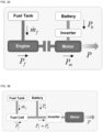
- FIGS. 3A and 3B illustrate exemplary configurations of a powertrain in a hybrid vehicle.
- a hybrid vehicle refers to a vehicle that uses two or more power sources, and generally uses two power sources of fuel and battery.
- FIG. 3A illustrates an example of using an engine as a fuel-based power conversion device (a parallel engine-electric hybrid powertrain)
- FIG. 3B illustrates an example of using a fuel cell as a fuel-based power conversion device (a fuel cell-electric hybrid powertrain).
- the instantaneous fuel consumption ( ⁇ f ) is converted to mechanical power or electrical power ( P f ) through the fuel power source, which is an engine ( FIG. 3A ) or a fuel cell ( FIG. 3B ).
- the power ( P f ) from this fuel power source is combined with the power generated from the battery to provide the power requested by the driver ( P ).
- the battery power ( P b ) is converted to mechanical power ( P m ) through the motor and then combined with P f to provide the requested power (P).
- the battery power ( P b ) is combined with P f to provide the requested power ( P ).
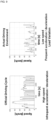
- FIG. 4 illustrates measurement results of fuel consumption according to power control strategies of a hybrid vehicle
- FIG. 5 illustrates an example of modeling results of instantaneous fuel consumption in a transient state when the fuel power source is an engine.
- P b is automatically determined when P f is determined for a given P , so it is a function of P and P f .
- P f corresponds to a control input
- P f , k ⁇ is the optimal control input command determined in the optimal power control problem.
- the usage of power sources ( ⁇ f , P b ) is determined by this control input command, and in the case of a parallel engine-electric hybrid powertrain, the motor power ( P m ) is also determined.
- power control is performed based on a steady-state model, but when power control is performed considering the transient state model of the fuel power source, significant efficiency improvement is required, especially in terms of fuel consumption reduction, as shown in FIG. 4 .
- the ⁇ f model at the transient state of the fuel power source has high complexity, making it difficult to ensure accuracy above 80% even with a complex function as shown in FIG. 5 . Due to this, there are limitations in the actual implementation of power control technology that reflects the transient state model of the fuel power source. Therefore, a power control technology that can reduce the transient operation of the fuel power source even without the transient state model is needed, and such technology can achieve maximization of performance (minimization of carbon emissions) in the actual operating environment of hybrid vehicles.
- Patent Reference 1 proposes a method of reducing additional fuel consumption occurring in transient operation by controlling the engine torque through a fast path only under conditions requiring a fast response and controlling the engine torque through a slow path under other conditions.
- Patent Reference 2 proposes a method of limiting the transient operation of the engine by limiting the rate of change of engine torque and engine power.
- Patent Reference 3 proposes a method of pre-defining an engine torque range with high efficiency (torque band lower limit ⁇ upper limit) and operating the engine only within this range in a limited manner.
- Patent Reference 4 performs power control by additionally reflecting a fuel consumption model caused by the engine turbocharger.
- power control is performed by additionally reflecting fuel consumption models caused by engine start and smoke limit.
- the engine has various types of transient operation, and as shown in the example of FIG. 5 , there is a limitation in the accuracy of the transient state model of the engine. Therefore, it lacks some practicality to become a general power control method, and although it can reduce the transient operation of the engine itself, since the efficiency characteristics of the motor are not considered together, there is a limitation in optimizing the efficiency of the entire hybrid system.
- FIG. 6 illustrates an example of a configuration of a conventional control device (100) for an engine-electric hybrid vehicle.
- the control device in FIG. 6 applies a rate or range limitation to the fuel power output (or torque) determined in the power control unit.
- a rate or range limitation to the fuel power output (or torque) determined in the power control unit.
- FIG. 7 illustrates a configuration of a control device (200) for a hybrid vehicle considering transient characteristics according to the present invention.
- the core of the present invention lies in that the average value ( P ) of the driver's requested power ( P ) for a specific time domain is calculated by the average requested power calculation unit (210), and the fuel power output command ( P f ⁇ ) is determined by the fuel power output calculation unit (220) of the power control unit for this average requested power ( P ) .
- the driver's requested power ( P ) is continuously received by the communication unit (not shown) of the control device (200) for a hybrid vehicle considering transient characteristics from the control device of the hybrid vehicle, and the average requested power calculation unit calculates the average requested power P from this.
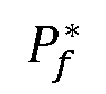
- the fuel power output command ( P f ⁇ ) determined in this way means a single value that minimizes the equivalent fuel consumption for a specific time domain, and P f ⁇ changes very slowly according to P , so it has an advantage of being able to greatly reduce the transient operation of the fuel power source.
- the present invention determines the optimal fuel power output command ( P f ⁇ ) (Equation (2b)) that minimizes m ⁇ ⁇ eq shown in Equation (2a) of Expression 2, which is the average equivalent fuel consumption for a specific time domain.
- the fuel power output command P f ⁇ to be determined becomes a function of the average requested power P since the average calculation is applied to the variable P.
- Patent References 1, 2, and 3, as described in FIG. 6 apply a rate or range limitation to the fuel power output (or torque) determined in the power control unit. In these methods, since the efficiency characteristics of the motor are not considered together in the reduction of the transient operation of the fuel power source, optimal system performance cannot be derived.
- the optimal power control result considering the motor efficiency characteristics is derived from Expression 2, and in the extreme case where the average requested power ( P ) is constant in the driving environment, a static (fixed) fuel power output value can be derived. This means that system performance optimization and reduction of transient operation of the fuel power source are performed simultaneously.
- Patent Reference 2 and other previous studies were based on the optimal power control problem, but did not secure generality due to the limited application of the transient state model of the fuel power source.
- the present invention can simultaneously perform system performance optimization and reduction of transient operation of the fuel power source by determining and applying the fuel power output command P f ⁇ using Expression 2 even without such a transient state model of the fuel power source.
- the battery-based power command can be calculated from the determined P f * and P by a battery-based power calculation unit (230).
- the battery-based power is the power directly derived from the battery. That is, as described above, the power control method of the present invention and the device performing the method determine the fuel power output command P f * using Expression 2, and determine the battery-based power according to the requested power from that.
- the power control method described above is also applicable when the fuel cell-electric hybrid powertrain of FIG. 3B is used as the powertrain.
- the power control method of the present invention and the device performing the method are not only applicable to the parallel engine-electric hybrid powertrain described in FIG. 3A , but also to engine-electric hybrid powertrains with other topologies (plug-in, power split, series, etc.), and can be extensively applied to general hybrid vehicles including the fuel cell-electric hybrid vehicle of FIG. 3B .
- the motor speed signal w m and engine (fuel power source) speed signal w f are not included.
- the battery-based power is P b of Expression 2 in the case of the fuel cell-electric hybrid powertrain of FIG. 3B , and is the motor power P m determined from P b , as shown in FIG. 7 , in the case of the engine-electric hybrid powertrain of FIG. 3A .
- the battery-based power refers to the motor power ( P m ), and the motor power ( P m ) is determined by the difference between the requested power ( P ) and the fuel power output ( P f ), so can be expressed as Equation 4c.
- Equation 5 ⁇ r ⁇ 1 + 2 r 2 P ⁇ ⁇ q ⁇ 1 2 ⁇ r ⁇ 2 + q ⁇ 2 .
- This solution is expressed as a function of the average requested power ( P ) as described above, and also includes the average values of the coefficients of the ⁇ f and P b model, that is, r 1 , r 2 , q 1 , q 2 in the example of the engine-electric hybrid powertrain.
- the coefficients r 1 , r 2 , q 1 , q 2 are functions of the engine (fuel power source) speed w f or motor speed w m , respectively, as shown in the above equation, so they change over time, and accordingly, their average values are also applied as shown in Expression 5.
- Equations 4a and 4c of the engine-electric hybrid powertrain are functions of the engine (fuel power source) speed w f or motor speed w m , respectively, so they change over time, and accordingly, their average values are also applied as shown in Expression 5.
- Equations 7a and 7b are constants that do not change over time, so there is no need to apply average values to those coefficients.
- the result is the same value, so it can be seen that the fuel power output equation of Expression 5 applied to the engine-electric hybrid powertrain and the fuel power output equation of Expression 8 applied to the fuel cell-electric powertrain have the same form.
- the coefficients s 0 , s 1 , s 2 , t 0 , t 1 , t 2 in Expression 7 can be derived through the characteristic values of the fuel power source and battery, respectively, or derived through experimental data.
- Expression 6 which limits the range of the fuel power output command ( P f ⁇ ) determined by Expression 5 in the engine-electric hybrid powertrain, is also applied identically to the fuel power output command ( P f ⁇ ) determined by Expression 8 in the fuel cell-electric powertrain.
- This battery-based power command is the motor power command ( P m ⁇ ) in the engine-electric hybrid powertrain of FIG. 3A .
- the battery-based power command is the battery power command ( P b ⁇ ) in the fuel cell-electric hybrid powertrain of FIG. 3B and applied to the control.
- FIG. 8 is a flowchart of a method in which the control device (200) for a hybrid vehicle considering transient characteristics performs power control.
- the average requested power calculation unit (210) calculates the average requested power ( P ) from the input of the current requested power ( P ) received from the hybrid vehicle (S801).
- the equivalent fuel consumption ( ⁇ eq ) is determined as the weighted sum of the instantaneous fuel consumption ( ⁇ f ) and battery power ( P b ), and the optimal fuel power output command ( P f ⁇ ) to be obtained is determined as the value that minimizes the average equivalent fuel consumption m ⁇ ⁇ eq shown in Equation (2a) of Expression 2 (Equation (2b)) (S802).
- the optimal fuel power output command ( P f ⁇ ) to be determined becomes a function of the average requested power ( P ), so the optimal fuel power output command ( P f * ) value is eventually determined by the average requested power ( P ) value calculated in step S801.
- the instantaneous fuel consumption ( ⁇ f ) and battery power ( P b ) can be expressed by modeled equations, an example of the modeled equations in the engine-electric hybrid powertrain ( FIG. 3A ) is shown in Expression 4, and an example of the modeled equations in the fuel cell-electric hybrid powertrain ( FIG. 3B ) is shown in Expression 7.
- the average values of the coefficients included in the models of the instantaneous fuel consumption ( ⁇ f ) and battery power ( P b ) must be calculated.
- the average values of the coefficients included in the models of the instantaneous fuel consumption ( ⁇ f ) and battery power ( P b ) are r 1 , r 2 , q 1 , q 2 , as described above, in the example of the engine-electric hybrid powertrain.
- the current fuel power source speed (w f ) and the current motor speed (w m ) are received as inputs.
- the coefficients s 0 , s 1 , s 2 , t 0 , t 1 , t 2 in Expressions 7A and 7B are constants that do not change over time, respectively, so there is no need to apply average values to those coefficients.
- the result is the same value, so it can be seen that the fuel power output equation of Expression 5 applied to the engine-electric hybrid powertrain and the fuel power output equation of Expression 8 applied to the fuel cell-electric powertrain have the same form.
- the P f * can be limited as shown in Expression 6 (S803).
- the battery-based power command is calculated from the fuel power output command ( P f * ) and the requested power ( P ) (S804).
- the battery-based power command determined and calculated here is the battery power command ( P b ⁇ ) in the case of the fuel cell-electric hybrid powertrain of FIG. 3B , or the motor power command ( P m ⁇ ) in the case of the engine-electric hybrid powertrain of FIG. 3A .
- the motor power command is calculated as and applied to the control.
- the power control device (200) for a hybrid vehicle considering transient characteristics sends the fuel power output command ( P f ⁇ ) and the battery-based power command determined in this way to the fuel power source control unit and the battery-based power control unit of the hybrid vehicle to control them.
- the fuel power source that is, the engine power is controlled by the fuel power output command ( P f ⁇ )
- the motor power is controlled by the battery-based power command (S805).
- the fuel power source that is, the fuel cell power is controlled by the fuel power output command ( P f ⁇ )
- the battery power is controlled by the battery-based power command (S805).
- FIG. 9 is a diagram for comparing the official driving cycle and the actual driving environment of a commercial vehicle.
- the power control method of the present invention in which the reduction of transient operation of the fuel power source and the optimization of hybrid system performance are simultaneously performed, is particularly effective in commercial hybrid vehicles.
- FIG. 10 shows the actual fuel efficiency and performance by driving environment according to the control method of the present invention in comparison with the results according to the conventional algorithm.
- FIG. 11 shows the simulation results of engine torque and instantaneous fuel consumption of an engine-electric hybrid vehicle to which the control method of the present invention is applied.
- the conventional method generates a lot of transient operations in the engine torque ( T e ), but the present invention greatly reduces the transient operation of the engine torque.
- the instantaneous fuel consumption ( ⁇ f ) in the conventional invention includes a lot of transient components, resulting in additional fuel consumption more than necessary, while the transient components of fuel consumption are greatly reduced in the results of the present invention.
- FIG. 12 shows the simulation results of fuel efficiency and carbon emissions of an engine-electric hybrid vehicle to which the control method of the present invention is applied.
- the fuel efficiency and carbon emissions of each power control method derived as simulation results are summarized.
- the present invention improved fuel efficiency and reduced carbon emissions by more than 4% compared to the conventional method, and it can be seen that the effect increases as N increases. Through this, it can be confirmed that the present invention is an effective power control strategy for reducing engine transient operation and optimizing the overall performance of the hybrid system.
Landscapes
- Engineering & Computer Science (AREA)
- Transportation (AREA)
- Mechanical Engineering (AREA)
- Chemical & Material Sciences (AREA)
- Combustion & Propulsion (AREA)
- Automation & Control Theory (AREA)
- Human Computer Interaction (AREA)
- Electric Propulsion And Braking For Vehicles (AREA)
Abstract
Description
- The present invention relates to a power control method and apparatus that considers the transient characteristics of a hybrid vehicle, and more specifically, to a power control method and apparatus that maximizes the performance of a hybrid vehicle in an actual operating environment by reducing fuel power source transients.
-
FIG. 1A is a diagram illustrating an engine fuel consumption map in a hybrid vehicle in a steady state,FIG. 1B is a diagram illustrating a motor efficiency map in a hybrid vehicle in a steady state, andFIG. 2 is a diagram illustrating a fuel consumption characteristic in a transient state when the fuel source is an engine. - Referring to
FIGS. 1A and1B , it can be seen that the fuel power source consumes less fuel per energy at medium to high power range, and the motor is efficient throughout the driving range. In particular, referring toFIG. 2 , it can be seen that the fuel power source has different fuel consumption characteristics in the transient state than in the steady state. That is, there is a large difference in fuel consumption amount between the measured value ( ṁf·meas ) and the calculated value of the steady-state fuel map ( ṁf·SS ) during transients such as starting and power changes. Considering these results, to maximize the performance and efficiency of hybrid vehicles, such as reducing fuel consumption, a power control strategy is needed to solve transient state problems by taking into account the efficiency characteristics of the two power sources. -
- (Patent Reference 1)
KR 10-1766092 B1 - (Patent Reference 2)
US 2011-0166730 A1 - (Patent Reference 3)
US 8473133 B2 - (Patent Reference 4)
KR 10-1634489 B1 - The present invention was devised to solve these problems. Its purpose is to provide a method and apparatus that can effectively solve the optimal power control problem without a transient state model of the fuel power source, thereby reducing the transient operation of the fuel power source and maximizing the performance of hybrid vehicles in real-world driving conditions.
- To achieve this object, there is provided a power control method considering the transient characteristics of a hybrid vehicle, comprising: (a) receiving a current requested power value from the hybrid vehicle; (b) calculating an average requested power from the received plurality of requested power values; (c) calculating an optimal fuel power output command value that minimizes an average equivalent fuel consumption for the average requested power; (d) calculating a battery-based power command from the optimal fuel power output command calculated in step (c) and the requested power value; and (e) transmitting the optimal fuel power output command and the battery-based power command to a control system of the hybrid vehicle.
- Preferably, the average equivalent fuel consumption is defined as a weighted sum of average fuel consumption and average battery power expressed as

- The power control method may further comprise between step (c) and step (d), a step of: (c1) determining the fuel power output command as an allowable minimum value of the fuel power output if the fuel power output command value calculated in step (c) is less than or equal to the allowable minimum value of the fuel power output, determining the fuel power output command as an allowable maximum value of the fuel power output if the calculated fuel power output command value is greater than or equal to the allowable maximum value of the fuel power output, and determining the fuel power output command as the calculated fuel power output command value if the calculated fuel power output command value is between the allowable maximum value and the allowable minimum value of the fuel power output.
- Preferably, when the hybrid vehicle uses an engine-electric hybrid powertrain, the instantaneous fuel amount model equation is


- Preferably, the optimal fuel power output command is determined as

- Preferably, when the hybrid vehicle uses an engine-electric hybrid powertrain, the battery-based power command calculated in step (d) is a motor power command.
- Preferably, when the hybrid vehicle uses a fuel cell-electric hybrid powertrain, the instantaneous fuel amount model equation is


- Preferably, the optimal fuel power output command is determined as

- Preferably, when the hybrid vehicle uses a fuel cell-electric hybrid powertrain, the battery-based power command calculated in step (d) is a battery power command. According to other aspect of the present invention, there is provided an apparatus for performing power control considering the transient characteristics of a hybrid vehicle, comprising: at least one processor; and at least one memory storing computer-executable instructions, wherein the computer-executable instructions stored in the at least one memory cause the at least one processor to perform: (a) receiving a current requested power value from the hybrid vehicle; (b) calculating an average requested power from the received plurality of requested power values; (c) calculating an optimal fuel power output command value that minimizes an average equivalent fuel consumption for the average requested power; (d) calculating a battery-based power command from the optimal fuel power output command calculated in step (c) and the requested power value; and (e) transmitting the optimal fuel power output command and the battery-based power command to a control system of the hybrid vehicle. According to another aspect of the present invention, there is provided a computer program for performing power control considering the transient characteristics of a hybrid vehicle, stored on a non-transitory storage medium, and comprising instructions that cause a processor to perform: (a) receiving a current requested power value from the hybrid vehicle; (b) calculating an average requested power from the received plurality of requested power values; (c) calculating an optimal fuel power output command value that minimizes an average equivalent fuel consumption for the average requested power; (d) calculating a battery-based power command from the optimal fuel power output command calculated in step (c) and the requested power value; and (e) transmitting the optimal fuel power output command and the battery-based power command to a control system of the hybrid vehicle.
- According to still another aspect of the present invention, there is provided an apparatus for power control considering the transient characteristics of a hybrid vehicle, comprising: an average requested power calculation unit that calculates an average requested power for the requested power value continuously received from a control unit of the hybrid vehicle; a fuel power output calculation unit that calculates an optimal fuel power output command value that minimizes an average equivalent fuel consumption for the average requested power value; a battery-based power calculation unit that calculates a battery-based power from the requested power value and the optimal fuel power output; and a communication unit that continuously receives the requested power value from the control unit of the hybrid vehicle and transmits the optimal fuel power output command and the battery-based power command to the control system of the hybrid vehicle.
- Preferably, the average equivalent fuel consumption is defined as a weighted sum of average fuel consumption and average battery power expressed as

- Preferably, the fuel power output calculation unit further includes a function of: determining the fuel power output command as an allowable minimum value of the fuel power output if the calculated fuel power output command value is less than or equal to the allowable minimum value of the fuel power output, determining the fuel power output command as an allowable maximum value of the fuel power output if the calculated fuel power output command value is greater than or equal to the allowable maximum value of the fuel power output, and determining the fuel power output command as the calculated fuel power output command value if the calculated fuel power output command value is between the allowable maximum value and the allowable minimum value of the fuel power output.
- Preferably, when the hybrid vehicle uses an engine-electric hybrid powertrain, the instantaneous fuel amount model equation is


- Preferably, the optimal fuel power output command is determined as

- Preferably, when the hybrid vehicle uses an engine-electric hybrid powertrain, the battery-based power command calculated by the battery-based power calculation unit is a motor power command.
- Preferably, when the hybrid vehicle uses a fuel cell-electric hybrid powertrain, the instantaneous fuel amount model equation is


- Preferably, the optimal fuel power output command is determined as

- Preferably, when the hybrid vehicle uses a fuel cell-electric hybrid powertrain, the battery-based power command calculated by the battery-based power calculation unit is a battery power command.
- According to the present invention, there is an effect of providing a method and apparatus that can effectively solve the optimal power control problem without a transient state model of the fuel power source, thereby reducing the transient operation of the fuel power source and maximizing the performance of hybrid vehicles in real-world driving conditions.
-
-
FIG. 1A is a diagram showing an engine fuel consumption map in a hybrid vehicle at a steady state. -
FIG. 1B is a diagram illustrating a motor efficiency map in a hybrid vehicle at a steady state. -
FIG. 2 is a diagram depicting a fuel consumption characteristic in a transient state when the fuel power source is an engine. -
FIG. 3A shows an embodiment of the powertrain configuration of a hybrid vehicle, an example of using an engine as a fuel-based power conversion device (a parallel engine-electric hybrid powertrain). -
FIG. 3B shows another embodiment of the powertrain configuration of a hybrid vehicle, an example of using a fuel cell as a fuel-based power conversion device (a fuel cell-electric hybrid powertrain). -
FIG. 4 is a diagram showing the measurement results of fuel consumption according to the power control strategy of a hybrid vehicle. -
FIG. 5 is a diagram illustrating an example of modeling results of instantaneous fuel consumption in a transient state when the fuel power source is an engine. -
FIG. 6 is a diagram illustrating an embodiment of a conventional control device configuration for an engine-electric hybrid vehicle. -
FIG. 7 is a diagram illustrating a control device configuration according to the present invention for an engine-electric hybrid vehicle. -
FIG. 8 is a flowchart of a method for performing power control considering the transient characteristics of a hybrid vehicle according to the present invention. -
FIG. 9 is a diagram for comparing the certified driving cycle and the real driving environment of a commercial vehicle. -
FIG. 10 is a diagram showing the actual fuel efficiency and performance according to the driving environment of the present invention's control method, compared with the results of the conventional algorithm. -
FIG. 11 is a diagram showing the simulation results of engine torque and instantaneous fuel consumption of an engine-electric hybrid vehicle applying the control method of the present invention. -
FIG. 12 is a diagram showing the simulation results of fuel efficiency and carbon emissions of an engine-electric hybrid vehicle applying the control method of the present invention. - Hereinafter, preferred embodiments of the present invention will be described in detail with reference to the accompanying drawings. Prior to that, the terms or words used in this specification and claims should not be construed as being limited to their common or dictionary meanings, and the inventor can appropriately define the concepts of terms based on the principle that terms can be properly defined to describe his/her own invention in the best way. Therefore, the embodiments described in this specification and the configurations shown in the drawings are merely the most preferred embodiments of the present invention, and do not represent all the technical ideas of the present invention. Thus, it should be understood that there may be various equivalents and modifications that can replace them at the time of this application.
-
FIGS. 3A and 3B illustrate exemplary configurations of a powertrain in a hybrid vehicle. - A hybrid vehicle refers to a vehicle that uses two or more power sources, and generally uses two power sources of fuel and battery.
FIG. 3A illustrates an example of using an engine as a fuel-based power conversion device (a parallel engine-electric hybrid powertrain), andFIG. 3B illustrates an example of using a fuel cell as a fuel-based power conversion device (a fuel cell-electric hybrid powertrain). The instantaneous fuel consumption ( ṁf ) is converted to mechanical power or electrical power ( Pf ) through the fuel power source, which is an engine (FIG. 3A ) or a fuel cell (FIG. 3B ). The power ( Pf ) from this fuel power source is combined with the power generated from the battery to provide the power requested by the driver (P). - In the case of a parallel engine-electric hybrid powertrain (
FIG. 3A ), the battery power ( Pb ) is converted to mechanical power ( Pm ) through the motor and then combined with Pf to provide the requested power (P). In the case of a fuel cell-electric hybrid powertrain (FIG. 3B ), the battery power ( Pb ) is combined with Pf to provide the requested power (P). -
FIG. 4 illustrates measurement results of fuel consumption according to power control strategies of a hybrid vehicle, andFIG. 5 illustrates an example of modeling results of instantaneous fuel consumption in a transient state when the fuel power source is an engine. - When a driving environment is given, the requested power (P) required to reach a defined speed at each time point is determined, and this power needs to be generated from two power sources (fuel and battery). The optimal power control problem can be defined as a problem of minimizing the equivalent fuel consumption ( ṁeq ), which is the weighted sum of the instantaneous fuel consumption ( ṁf ) and battery power ( Pb ), as follows:

- Pb is automatically determined when Pf is determined for a given P, so it is a function of P and Pf. Pf corresponds to a control input, and

- To solve the optimal power control equation of
Expression 1, models for fuel consumption ( ṁf ) and battery power ( Pb ) are needed. Since the requested power (P) changes over time, the fuel power output command (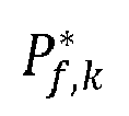
- Generally, power control is performed based on a steady-state model, but when power control is performed considering the transient state model of the fuel power source, significant efficiency improvement is required, especially in terms of fuel consumption reduction, as shown in
FIG. 4 . - However, the ṁf model at the transient state of the fuel power source has high complexity, making it difficult to ensure accuracy above 80% even with a complex function as shown in
FIG. 5 . Due to this, there are limitations in the actual implementation of power control technology that reflects the transient state model of the fuel power source. Therefore, a power control technology that can reduce the transient operation of the fuel power source even without the transient state model is needed, and such technology can achieve maximization of performance (minimization of carbon emissions) in the actual operating environment of hybrid vehicles. - Various technologies have been disclosed to solve this transient state problem.
-
Patent Reference 1 proposes a method of reducing additional fuel consumption occurring in transient operation by controlling the engine torque through a fast path only under conditions requiring a fast response and controlling the engine torque through a slow path under other conditions. -
Patent Reference 2 proposes a method of limiting the transient operation of the engine by limiting the rate of change of engine torque and engine power. -
Patent Reference 3 proposes a method of pre-defining an engine torque range with high efficiency (torque band lower limit ~ upper limit) and operating the engine only within this range in a limited manner. - These methods can reduce the transient operation of the engine itself, but since the efficiency characteristics of the motor are not considered together, there is a limitation in optimizing the efficiency of the entire hybrid system.
- Patent Reference 4 performs power control by additionally reflecting a fuel consumption model caused by the engine turbocharger.
- In another paper, power control is performed by additionally reflecting fuel consumption models caused by engine start and smoke limit.
- With these methods, it is possible to improve the efficiency of the hybrid system through the reduction of the transient operation of the engine (turbocharging, starting, smoke limit, etc.), which is the target of modeling. However, as shown in the example of
FIG. 2 , the engine has various types of transient operation, and as shown in the example ofFIG. 5 , there is a limitation in the accuracy of the transient state model of the engine. Therefore, it lacks some practicality to become a general power control method, and although it can reduce the transient operation of the engine itself, since the efficiency characteristics of the motor are not considered together, there is a limitation in optimizing the efficiency of the entire hybrid system. -
FIG. 6 illustrates an example of a configuration of a conventional control device (100) for an engine-electric hybrid vehicle. - The control device in
FIG. 6 applies a rate or range limitation to the fuel power output (or torque) determined in the power control unit. In this method, since the efficiency characteristics of the motor are not considered together in the reduction of the transient operation of the fuel power source, there is a problem that optimal system performance cannot be derived. -
FIG. 7 illustrates a configuration of a control device (200) for a hybrid vehicle considering transient characteristics according to the present invention. - The core of the present invention lies in that the average value (
P ) of the driver's requested power (P) for a specific time domain is calculated by the average requested power calculation unit (210), and the fuel power output command (
P ). The driver's requested power (P) is continuously received by the communication unit (not shown) of the control device (200) for a hybrid vehicle considering transient characteristics from the control device of the hybrid vehicle, and the average requested power calculation unit calculates the average requested powerP from this. - The fuel power output command (


P , so it has an advantage of being able to greatly reduce the transient operation of the fuel power source.
- In
Expression 2, when x is an arbitrary variable,
[Expression 3]
- The present invention determines the optimal fuel power output command (


Expression 2, which is the average equivalent fuel consumption for a specific time domain. The fuel power output command
P since the average calculation is applied to the variable P. -
P changes very slowly for a sufficiently large N and
P , so it has the advantage of being able to greatly reduce the transient operation of the fuel power source. - Patent References 1, 2, and 3, as described in
FIG. 6 , apply a rate or range limitation to the fuel power output (or torque) determined in the power control unit. In these methods, since the efficiency characteristics of the motor are not considered together in the reduction of the transient operation of the fuel power source, optimal system performance cannot be derived. - On the other hand, in the present invention, the optimal power control result considering the motor efficiency characteristics is derived from
Expression 2, and in the extreme case where the average requested power (P ) is constant in the driving environment, a static (fixed) fuel power output value can be derived. This means that system performance optimization and reduction of transient operation of the fuel power source are performed simultaneously. - In addition,
Patent Reference 2 and other previous studies were based on the optimal power control problem, but did not secure generality due to the limited application of the transient state model of the fuel power source. - On the other hand, the present invention can simultaneously perform system performance optimization and reduction of transient operation of the fuel power source by determining and applying the fuel power output command

Expression 2 even without such a transient state model of the fuel power source. - The battery-based power command can be calculated from the determined

P by a battery-based power calculation unit (230). Here, as described above, the battery-based power is the power directly derived from the battery. That is, as described above, the power control method of the present invention and the device performing the method determine the fuel power output command
Expression 2, and determine the battery-based power according to the requested power from that. - Meanwhile, although the powertrain shown in
FIG. 7 illustrates the engine-electric hybrid powertrain ofFIG. 3A , the power control method described above is also applicable when the fuel cell-electric hybrid powertrain ofFIG. 3B is used as the powertrain. Furthermore, the power control method of the present invention and the device performing the method are not only applicable to the parallel engine-electric hybrid powertrain described inFIG. 3A , but also to engine-electric hybrid powertrains with other topologies (plug-in, power split, series, etc.), and can be extensively applied to general hybrid vehicles including the fuel cell-electric hybrid vehicle ofFIG. 3B . - Furthermore, it can also be utilized as a power control method for other hybrid systems using two or more power sources.
- However, in
FIG. 7 , when using a fuel cell-electric hybrid powertrain, the motor speed signal wm and engine (fuel power source) speed signal wf are not included. In addition, the battery-based power is Pb ofExpression 2 in the case of the fuel cell-electric hybrid powertrain ofFIG. 3B , and is the motor power Pm determined from Pb , as shown inFIG. 7 , in the case of the engine-electric hybrid powertrain ofFIG. 3A . - Hereinafter, first, an example in which the power control method of the present invention considering transient characteristics is applied to the engine-electric hybrid powertrain of
FIG. 3A will be described in detail, and then an example in which the power control method of the present invention considering transient characteristics is applied to the fuel cell-electric hybrid powertrain ofFIG. 3B will be described in detail. - The steady-state models of instantaneous fuel consumption ( ṁf ) and battery power (Pb ) can be assumed to be modeled in the following form:

- In the engine-electric hybrid powertrain of
FIG. 3A , the battery-based power refers to the motor power (Pm ), and the motor power (Pm ) is determined by the difference between the requested power (P) and the fuel power output (Pf ), so can be expressed as Equation 4c. - The functional relationships of the coefficients q0, q1, q2, r0, r1, r2 in Expression 4 with respect to speed (wf, wm) can be derived through the characteristic values of the fuel power source, motor, and battery, respectively, or derived through experimental data.
- By substituting Equations 4a and 4c into Equation 2a and then calculating


[Expression 5]
- This solution is expressed as a function of the average requested power (
P ) as described above, and also includes the average values of the coefficients of the ṁf and Pb model, that is,r 1,r 2,q 1 ,q 2 in the example of the engine-electric hybrid powertrain. In other words, the coefficients r1, r2, q1, q2 are functions of the engine (fuel power source) speed wf or motor speed wm, respectively, as shown in the above equation, so they change over time, and accordingly, their average values are also applied as shown inExpression 5. - If N used in the average calculation is very large or the change in the driving environment is not significant, these average values are calculated almost constantly, and this solution (

- If the fuel power output command (
Expression 5 is determined outside the allowable set (P) of the fuel power output, that is, if


[Expression 6]
- This method is different from limiting the rate of change or range of the fuel power output (torque) in
Patent References - The steady-state models of instantaneous fuel consumption ( ṁf ) and battery power (Pb ) can be assumed to be modeled in the following form:

- By substituting Equations 7a and 7b into Equation 2a and then calculating


[Expression 8]
- The coefficients r1, r2, q1, q2 applied in Equations 4a and 4c of the engine-electric hybrid powertrain are functions of the engine (fuel power source) speed wf or motor speed wm, respectively, so they change over time, and accordingly, their average values are also applied as shown in
Expression 5. - However, in the fuel cell-electric powertrain, there are no wf and wm, and therefore, the coefficients s0, s1, s2, t0, t1, t2 applied in Equations 7a and 7b are constants that do not change over time, so there is no need to apply average values to those coefficients. However, even if the average values are applied to each constant coefficient, the result is the same value, so it can be seen that the fuel power output equation of
Expression 5 applied to the engine-electric hybrid powertrain and the fuel power output equation of Expression 8 applied to the fuel cell-electric powertrain have the same form. - The coefficients s0, s1, s2, t0, t1, t2 in
Expression 7 can be derived through the characteristic values of the fuel power source and battery, respectively, or derived through experimental data. - Expression 6, which limits the range of the fuel power output command (

Expression 5 in the engine-electric hybrid powertrain, is also applied identically to the fuel power output command (
- Finally, the battery-based power command is calculated. This battery-based power command is the motor power command (

FIG. 3A . - The motor power command is calculated as


FIG. 3B and applied to the control. -
FIG. 8 is a flowchart of a method in which the control device (200) for a hybrid vehicle considering transient characteristics performs power control. - The power control method for a hybrid vehicle considering transient characteristics according to the present invention has already been described in detail with reference to the power control device (200) of the present invention in
FIG. 7 , so hereinafter, the process will be briefly summarized and described as a flowchart. - The average requested power calculation unit (210) calculates the average requested power (
P ) from the input of the current requested power (P) received from the hybrid vehicle (S801). - The equivalent fuel consumption ( ṁeq ) is determined as the weighted sum of the instantaneous fuel consumption ( ṁf ) and battery power (Pb ), and the optimal fuel power output command (


P ), so the optimal fuel power output command (
P ) value calculated in step S801. - The instantaneous fuel consumption ( ṁf ) and battery power (Pb ) can be expressed by modeled equations, an example of the modeled equations in the engine-electric hybrid powertrain (
FIG. 3A ) is shown in Expression 4, and an example of the modeled equations in the fuel cell-electric hybrid powertrain (FIG. 3B ) is shown inExpression 7. - At this time, when Expression 4 or
Expression 7 is applied to Equation (2a) ofExpression 2, and accordingly, the value of the optimal fuel power output command (

Expression 5 or Expression 8. - Therefore, in order to determine the optimal fuel power output command (

Expression 5 in the engine-electric hybrid powertrain (FIG. 3A ), the average values of the coefficients included in the models of the instantaneous fuel consumption ( ṁf ) and battery power (Pb ) must be calculated. The average values of the coefficients included in the models of the instantaneous fuel consumption ( ṁf ) and battery power (Pb ) arer 1 ,r 2 ,q 1 ,q 2 , as described above, in the example of the engine-electric hybrid powertrain. In this case, the current fuel power source speed (wf) and the current motor speed (wm) are received as inputs. - In addition, as described above, in the fuel cell-electric hybrid powertrain (
FIG. 3B ), the coefficients s0, s1, s2, t0, t1, t2 in Expressions 7A and 7B are constants that do not change over time, respectively, so there is no need to apply average values to those coefficients. However, even if the average values are applied to each constant coefficient, the result is the same value, so it can be seen that the fuel power output equation ofExpression 5 applied to the engine-electric hybrid powertrain and the fuel power output equation of Expression 8 applied to the fuel cell-electric powertrain have the same form. - If the determined optimal fuel power output command (


- After that, the battery-based power command is calculated from the fuel power output command (


FIG. 3B , or the motor power command (
FIG. 3A . The motor power command is calculated as and applied to the control. - The power control device (200) for a hybrid vehicle considering transient characteristics sends the fuel power output command (

- In the engine-electric hybrid vehicle of
FIG. 3A , the fuel power source, that is, the engine power is controlled by the fuel power output command (
FIG. 3B , the fuel power source, that is, the fuel cell power is controlled by the fuel power output command (
-
FIG. 9 is a diagram for comparing the official driving cycle and the actual driving environment of a commercial vehicle. - As shown in
FIG. 9 , commercial vehicles such as buses and trucks are operated under harsh conditions of (1) frequent stopping, acceleration, and deceleration, and (2) real-time load variation according to the change in cargo load, and this actual driving environment is significantly different from the official driving cycle (FTP75, etc.) for evaluating vehicle fuel efficiency performance. - The performance (fuel efficiency, carbon emissions) of commercial vehicles operating in such an environment with severe load variations is greatly affected by the transient operation of the fuel power source, and even if they are hybridized, performance optimization (minimization of carbon emissions) is difficult to achieve with the existing power control method that does not consider the transient characteristics of the fuel power source.
- The power control method of the present invention, in which the reduction of transient operation of the fuel power source and the optimization of hybrid system performance are simultaneously performed, is particularly effective in commercial hybrid vehicles.
-
FIG. 10 shows the actual fuel efficiency and performance by driving environment according to the control method of the present invention in comparison with the results according to the conventional algorithm. - As shown in
FIG. 10 , according to the power control method for a hybrid vehicle considering transient characteristics of the present invention, it is possible to maximize the actual fuel efficiency and minimize the performance variation by driving environment. -
FIG. 11 shows the simulation results of engine torque and instantaneous fuel consumption of an engine-electric hybrid vehicle to which the control method of the present invention is applied. - Referring to the simulation results in
FIG. 11 , the conventional method generates a lot of transient operations in the engine torque (Te ), but the present invention greatly reduces the transient operation of the engine torque. In particular, as the number of time steps (N) used in the average calculation increases, the effect becomes greater. As a result, the instantaneous fuel consumption ( ṁf ) in the conventional invention includes a lot of transient components, resulting in additional fuel consumption more than necessary, while the transient components of fuel consumption are greatly reduced in the results of the present invention. -
FIG. 12 shows the simulation results of fuel efficiency and carbon emissions of an engine-electric hybrid vehicle to which the control method of the present invention is applied. - The fuel efficiency and carbon emissions of each power control method derived as simulation results are summarized. The present invention improved fuel efficiency and reduced carbon emissions by more than 4% compared to the conventional method, and it can be seen that the effect increases as N increases. Through this, it can be confirmed that the present invention is an effective power control strategy for reducing engine transient operation and optimizing the overall performance of the hybrid system.
Claims (20)
- A power control method considering the transient characteristics of a hybrid vehicle, comprising:(a) receiving a current requested power value from the hybrid vehicle;(b) calculating an average requested power from the received plurality of requested power values;(c) calculating an optimal fuel power output command value that minimizes an average equivalent fuel consumption for the average requested power;(d) calculating a battery-based power command from the optimal fuel power output command calculated in step (c) and the requested power value; and(e) transmitting the optimal fuel power output command and the battery-based power command to a control system of the hybrid vehicle.
- The power control method of claim 1, whereinthe average equivalent fuel consumption is defined as a weighted sum of average fuel consumption and average battery power expressed as
 where λ is the equivalence factor.
 - The power control method of claim 1, further comprising, between step (c) and step (d), a step of:
(c1) determining the fuel power output command as an allowable minimum value of the fuel power output if the fuel power output command value calculated in step (c) is less than or equal to the allowable minimum value of the fuel power output, determining the fuel power output command as an allowable maximum value of the fuel power output if the calculated fuel power output command value is greater than or equal to the allowable maximum value of the fuel power output, and determining the fuel power output command as the calculated fuel power output command value if the calculated fuel power output command value is between the allowable maximum value and the allowable minimum value of the fuel power output. - The power control method of claim 2, wherein,when the hybrid vehicle uses an engine-electric hybrid powertrain,the instantaneous fuel amount model equation is

 where the motor power (Pm ) is determined by the difference between the requested power (P) and the fuel power output (Pf ),wm is the motor speed, wf is the engine speed,q0, q1, q2 are each a function of wf, and r0, r1, r2 are each a function of wm.
 - The power control method of claim 4, wherein
the optimal fuel power output command is determined as
- The power control method of claim 4, wherein,when the hybrid vehicle uses an engine-electric hybrid powertrain,the battery-based power command calculated in step (d) is a motor power command.
- The power control method of claim 2, wherein,when the hybrid vehicle uses a fuel cell-electric hybrid powertrain,the instantaneous fuel amount model equation is
 and the battery power model equation is
- The power control method of claim 7, wherein
the optimal fuel power output command is determined as
- The power control method of claim 7, wherein,when the hybrid vehicle uses a fuel cell-electric hybrid powertrain,the battery-based power command calculated in step (d) is a battery power command.
- An apparatus for performing power control considering the transient characteristics of a hybrid vehicle, comprising:at least one processor; andat least one memory storing computer-executable instructions,wherein the computer-executable instructions stored in the at least one memory cause the at least one processor to perform:(a) receiving a current requested power value from the hybrid vehicle;(b) calculating an average requested power from the received plurality of requested power values;(c) calculating an optimal fuel power output command value that minimizes an average equivalent fuel consumption for the average requested power;(d) calculating a battery-based power command from the optimal fuel power output command calculated in step (c) and the requested power value; and(e) transmitting the optimal fuel power output command and the battery-based power command to a control system of the hybrid vehicle.
- A computer program for performing power control considering the transient characteristics of a hybrid vehicle,
stored on a non-transitory storage medium, and comprising instructions that cause a processor to perform:(a) receiving a current requested power value from the hybrid vehicle;(b) calculating an average requested power from the received plurality of requested power values;(c) calculating an optimal fuel power output command value that minimizes an average equivalent fuel consumption for the average requested power;(d) calculating a battery-based power command from the optimal fuel power output command calculated in step (c) and the requested power value; and(e) transmitting the optimal fuel power output command and the battery-based power command to a control system of the hybrid vehicle. - An apparatus for power control considering the transient characteristics of a hybrid vehicle, comprising:an average requested power calculation unit that calculates an average requested power for the requested power value continuously received from a control unit of the hybrid vehicle;a fuel power output calculation unit that calculates an optimal fuel power output command value that minimizes an average equivalent fuel consumption for the average requested power value;a battery-based power calculation unit that calculates a battery-based power from the requested power value and the optimal fuel power output; anda communication unit that continuously receives the requested power value from the control unit of the hybrid vehicle and transmits the optimal fuel power output command and the battery-based power command to the control system of the hybrid vehicle.
- The apparatus of claim 12, whereinthe average equivalent fuel consumption is defined as a weighted sum of average fuel consumption and average battery power expressed as
 where λ is the equivalence factor.
 - The apparatus of claim 12, wherein
the fuel power output calculation unit further includes a function of:determining the fuel power output command as an allowable minimum value of the fuel power output if the calculated fuel power output command value is less than or equal to the allowable minimum value of the fuel power output,determining the fuel power output command as an allowable maximum value of the fuel power output if the calculated fuel power output command value is greater than or equal to the allowable maximum value of the fuel power output, anddetermining the fuel power output command as the calculated fuel power output command value if the calculated fuel power output command value is between the allowable maximum value and the allowable minimum value of the fuel power output. - The apparatus of claim 13, wherein,when the hybrid vehicle uses an engine-electric hybrid powertrain,the instantaneous fuel amount model equation is
 and the battery power model equation is
 where the motor power (Pm ) is determined by the difference between the requested power (P) and the fuel power output (Pf ),wm is the motor speed, wf is the engine speed,q0, q1, q2 are each a function of wf, and r0, r1, r2 are each a function of wm.
 - The apparatus of claim 15, wherein
the optimal fuel power output command is determined as
- The apparatus of claim 15, wherein,when the hybrid vehicle uses an engine-electric hybrid powertrain,the battery-based power command calculated by the battery-based power calculation unit is a motor power command.
- The apparatus of claim 13, wherein,when the hybrid vehicle uses a fuel cell-electric hybrid powertrain,the instantaneous fuel amount model equation is
 and the battery power model equation is
- The apparatus of claim 18, wherein
the optimal fuel power output command is determined as
- The apparatus of claim 18, wherein,when the hybrid vehicle uses a fuel cell-electric hybrid powertrain,the battery-based power command calculated by the battery-based power calculation unit is a battery power command.
Applications Claiming Priority (2)
| Application Number | Priority Date | Filing Date | Title |
|---|---|---|---|
| KR20210144773 | 2021-10-27 | ||
| PCT/KR2022/016588 WO2023075455A1 (en) | 2021-10-27 | 2022-10-27 | Method and device for controlling power through consideration of transient characteristics of hybrid vehicle |
Publications (2)
| Publication Number | Publication Date |
|---|---|
| EP4424564A1 true EP4424564A1 (en) | 2024-09-04 |
| EP4424564A4 EP4424564A4 (en) | 2025-09-10 |
Family
ID=86158176
Family Applications (1)
| Application Number | Title | Priority Date | Filing Date |
|---|---|---|---|
| EP22887650.4A Pending EP4424564A4 (en) | 2021-10-27 | 2022-10-27 | Method and device for power control taking into account transient characteristics of a hybrid vehicle |
Country Status (4)
| Country | Link |
|---|---|
| US (1) | US20240278768A1 (en) |
| EP (1) | EP4424564A4 (en) |
| KR (1) | KR102701529B1 (en) |
| WO (1) | WO2023075455A1 (en) |
Families Citing this family (1)
| Publication number | Priority date | Publication date | Assignee | Title |
|---|---|---|---|---|
| CN121273485B (en) * | 2025-12-11 | 2026-04-03 | 吉林大学 | A data-driven method and system for correcting transient fuel consumption in engines |
Family Cites Families (18)
| Publication number | Priority date | Publication date | Assignee | Title |
|---|---|---|---|---|
| KR101114381B1 (en) * | 2009-11-19 | 2012-02-14 | 현대자동차주식회사 | Economic driving control device and method of hybrid vehicle |
| RU2527607C1 (en) * | 2010-07-26 | 2014-09-10 | Ниссан Мотор Ко., Лтд. | Vehicle |
| US8285470B2 (en) | 2010-10-29 | 2012-10-09 | Ford Global Technologies, Llc | Engine transient mitigation for hybrid vehicles |
| KR101260030B1 (en) * | 2011-03-04 | 2013-05-06 | 한양대학교 산학협력단 | Power distribution method for series hybrid electric vehicle |
| US8473133B2 (en) | 2011-04-19 | 2013-06-25 | Ford Global Technologies, Llc | Transient operation energy management strategy for a hybrid electric vehicle powertrain |
| US9539997B2 (en) * | 2014-07-29 | 2017-01-10 | Cummins Inc. | Method of power split for hybrid powertrain |
| DE102015202216A1 (en) * | 2014-09-19 | 2016-03-24 | Robert Bosch Gmbh | Method and device for operating a motor vehicle by specifying a desired speed |
| KR101634489B1 (en) | 2015-01-29 | 2016-06-28 | 한양대학교 산학협력단 | Power control apparatus and method considering transient state of diesel hydrid cars |
| KR101714215B1 (en) * | 2015-09-10 | 2017-03-22 | 현대자동차주식회사 | System and method for changing driving mode of hybrid vehicle |
| KR101766092B1 (en) | 2015-12-14 | 2017-08-07 | 현대자동차주식회사 | Control method of hybrid electric vehicle |
| KR101816247B1 (en) * | 2016-12-09 | 2018-01-08 | 현대오트론 주식회사 | Method to distribute engine and motor torque according to change rate of demand torque for hybrid electric vehicle |
| WO2018209038A1 (en) * | 2017-05-12 | 2018-11-15 | Ohio State Innovation Foundation | Real-time energy management strategy for hybrid electric vehicles with reduced battery aging |
| JP6753368B2 (en) * | 2017-06-28 | 2020-09-09 | トヨタ自動車株式会社 | Hybrid vehicle |
| KR101995173B1 (en) * | 2018-06-07 | 2019-07-02 | 현대위아 주식회사 | Control method driving mild hybrid electric vehicle and apparatus the same |
| US11167744B2 (en) * | 2019-06-14 | 2021-11-09 | GM Global Technology Operations LLC | AI-enhanced nonlinear model predictive control of power split and thermal management of vehicle powertrains |
| US11254302B2 (en) * | 2020-05-26 | 2022-02-22 | Toyota Motor Engineering & Manufacturing North America, Inc. | Stabilized real time trajectory optimization for hybrid energy management utilizing connected information technologies |
| KR102508409B1 (en) * | 2021-01-25 | 2023-03-13 | 한국과학기술원 | Method and apparatus for controlling power of hybrid vehicle considering driving environment |
| US12415500B2 (en) * | 2023-05-25 | 2025-09-16 | Garrett Transportation I Inc. | Predictive power split with zero-emission zone handling |
-
2022
- 2022-10-27 EP EP22887650.4A patent/EP4424564A4/en active Pending
- 2022-10-27 WO PCT/KR2022/016588 patent/WO2023075455A1/en not_active Ceased
- 2022-10-27 KR KR1020220140414A patent/KR102701529B1/en active Active
-
2024
- 2024-04-29 US US18/648,697 patent/US20240278768A1/en active Pending
Also Published As
| Publication number | Publication date |
|---|---|
| US20240278768A1 (en) | 2024-08-22 |
| EP4424564A4 (en) | 2025-09-10 |
| KR20230060479A (en) | 2023-05-04 |
| WO2023075455A1 (en) | 2023-05-04 |
| KR102701529B1 (en) | 2024-09-04 |
Similar Documents
| Publication | Publication Date | Title |
|---|---|---|
| Chen et al. | Optimization of sizing and frequency control in battery/supercapacitor hybrid energy storage system for fuel cell ship | |
| Hou et al. | A comparison study of battery size optimization and an energy management strategy for FCHEVs based on dynamic programming and convex programming | |
| Song et al. | Pontryagin’s minimum principle-based real-time energy management strategy for fuel cell hybrid electric vehicle considering both fuel economy and power source durability | |
| Lee et al. | Energy management strategy of fuel cell electric vehicles using model-based reinforcement learning with data-driven model update | |
| EP3369604B1 (en) | Method and system for estimating remaining range of electric car, and electric car | |
| Zheng et al. | Fuel economy evaluation of fuel cell hybrid vehicles based on equivalent fuel consumption | |
| CN110015212B (en) | Apparatus and method for power demand distribution in fuel cell vehicles | |
| Shen et al. | Design and real-time controller implementation for a battery-ultracapacitor hybrid energy storage system | |
| CN104253463B (en) | System and method for limiting the power of battery | |
| Tang et al. | Degradation adaptive energy management strategy for FCHEV based on the Rule-DDPG method: Tailored to the current SOH of the powertrain | |
| US10056628B2 (en) | Method for controlling startup of fuel cell vehicle | |
| EP2889179B1 (en) | Control method and system of electric vehicle | |
| Hong et al. | Power control strategy optimization to improve energy efficiency of the hybrid electric propulsion ship | |
| Lin et al. | System-level model and stochastic optimal control for a PEM fuel cell hybrid vehicle | |
| US20130151115A1 (en) | System and method for controlling torque of engine | |
| US20220242388A1 (en) | Method and apparatus for controlling power of hybrid vehicle considering driving environment | |
| US20240278768A1 (en) | Method and apparatus for controlling power of hybrid vehicle considering transient characteristics | |
| Majed et al. | Neural network technique for hybrid electric vehicle optimization | |
| Yuan et al. | Wavelet transform-integrated rule-based energy management strategy for PEMFC hybrid vehicles: fuel cell stacks lifetime enhancement | |
| Schmid et al. | Efficient optimal control of plug-in-hybrid electric vehicles including explicit engine on/off decisions | |
| Planakis et al. | Nonlinear model predictive control for the transient load share management of a hybrid diesel-electric marine propulsion plant | |
| Kim et al. | Combined control/plant optimization of fuel cell hybrid vehicles | |
| CN120016555A (en) | Energy management strategy and related devices of hybrid energy storage system based on adaptive weight | |
| Kazemi et al. | Utilizing situational awareness for efficient control of powertrain in parallel hybrid electric vehicles | |
| Meier et al. | Model predictive control of HEVs with exhaust aftertreatment system at low ambient temperatures |
Legal Events
| Date | Code | Title | Description |
|---|---|---|---|
| STAA | Information on the status of an ep patent application or granted ep patent |
Free format text: STATUS: THE INTERNATIONAL PUBLICATION HAS BEEN MADE |
|
| PUAI | Public reference made under article 153(3) epc to a published international application that has entered the european phase |
Free format text: ORIGINAL CODE: 0009012 |
|
| STAA | Information on the status of an ep patent application or granted ep patent |
Free format text: STATUS: REQUEST FOR EXAMINATION WAS MADE |
|
| 17P | Request for examination filed |
Effective date: 20240527 |
|
| AK | Designated contracting states |
Kind code of ref document: A1 Designated state(s): AL AT BE BG CH CY CZ DE DK EE ES FI FR GB GR HR HU IE IS IT LI LT LU LV MC ME MK MT NL NO PL PT RO RS SE SI SK SM TR |
|
| DAV | Request for validation of the european patent (deleted) | ||
| DAX | Request for extension of the european patent (deleted) | ||
| A4 | Supplementary search report drawn up and despatched |
Effective date: 20250812 |
|
| RIC1 | Information provided on ipc code assigned before grant |
Ipc: B60W 20/13 20160101AFI20250806BHEP Ipc: B60W 30/184 20120101ALI20250806BHEP Ipc: B60W 30/188 20120101ALI20250806BHEP Ipc: B60W 50/00 20060101ALI20250806BHEP Ipc: B60W 10/06 20060101ALI20250806BHEP Ipc: B60W 10/08 20060101ALI20250806BHEP Ipc: B60W 20/16 20160101ALI20250806BHEP |
|
| STAA | Information on the status of an ep patent application or granted ep patent |
Free format text: STATUS: EXAMINATION IS IN PROGRESS |