EP4424531A1 - Motor vehicle suspension with integrated ducts - Google Patents
Motor vehicle suspension with integrated ducts Download PDFInfo
- Publication number
- EP4424531A1 EP4424531A1 EP24160232.5A EP24160232A EP4424531A1 EP 4424531 A1 EP4424531 A1 EP 4424531A1 EP 24160232 A EP24160232 A EP 24160232A EP 4424531 A1 EP4424531 A1 EP 4424531A1
- Authority
- EP
- European Patent Office
- Prior art keywords
- motor vehicle
- wheel
- duct
- suspension
- fluid flow
- Prior art date
- Legal status (The legal status is an assumption and is not a legal conclusion. Google has not performed a legal analysis and makes no representation as to the accuracy of the status listed.)
- Pending
Links
- 239000000725 suspension Substances 0.000 title claims abstract description 45
- 239000012530 fluid Substances 0.000 claims abstract description 33
- 230000003750 conditioning effect Effects 0.000 claims description 14
- 238000004804 winding Methods 0.000 description 4
- 230000009471 action Effects 0.000 description 2
- 230000008901 benefit Effects 0.000 description 2
- 238000010438 heat treatment Methods 0.000 description 2
- 230000006872 improvement Effects 0.000 description 2
- 230000003993 interaction Effects 0.000 description 2
- 239000007788 liquid Substances 0.000 description 2
- 239000012809 cooling fluid Substances 0.000 description 1
- 230000008878 coupling Effects 0.000 description 1
- 238000010168 coupling process Methods 0.000 description 1
- 238000005859 coupling reaction Methods 0.000 description 1
- 230000001419 dependent effect Effects 0.000 description 1
- 238000005265 energy consumption Methods 0.000 description 1
- 238000002955 isolation Methods 0.000 description 1
- 230000009467 reduction Effects 0.000 description 1
- 230000004044 response Effects 0.000 description 1
- 238000000926 separation method Methods 0.000 description 1
- 239000007787 solid Substances 0.000 description 1
Images



Classifications
-
- B—PERFORMING OPERATIONS; TRANSPORTING
- B60—VEHICLES IN GENERAL
- B60G—VEHICLE SUSPENSION ARRANGEMENTS
- B60G7/00—Pivoted suspension arms; Accessories thereof
- B60G7/001—Suspension arms, e.g. constructional features
-
- B—PERFORMING OPERATIONS; TRANSPORTING
- B60—VEHICLES IN GENERAL
- B60G—VEHICLE SUSPENSION ARRANGEMENTS
- B60G3/00—Resilient suspensions for a single wheel
- B60G3/18—Resilient suspensions for a single wheel with two or more pivoted arms, e.g. parallelogram
- B60G3/20—Resilient suspensions for a single wheel with two or more pivoted arms, e.g. parallelogram all arms being rigid
-
- B—PERFORMING OPERATIONS; TRANSPORTING
- B60—VEHICLES IN GENERAL
- B60K—ARRANGEMENT OR MOUNTING OF PROPULSION UNITS OR OF TRANSMISSIONS IN VEHICLES; ARRANGEMENT OR MOUNTING OF PLURAL DIVERSE PRIME-MOVERS IN VEHICLES; AUXILIARY DRIVES FOR VEHICLES; INSTRUMENTATION OR DASHBOARDS FOR VEHICLES; ARRANGEMENTS IN CONNECTION WITH COOLING, AIR INTAKE, GAS EXHAUST OR FUEL SUPPLY OF PROPULSION UNITS IN VEHICLES
- B60K7/00—Disposition of motor in, or adjacent to, traction wheel
- B60K7/0007—Disposition of motor in, or adjacent to, traction wheel the motor being electric
-
- B—PERFORMING OPERATIONS; TRANSPORTING
- B60—VEHICLES IN GENERAL
- B60R—VEHICLES, VEHICLE FITTINGS, OR VEHICLE PARTS, NOT OTHERWISE PROVIDED FOR
- B60R16/00—Electric or fluid circuits specially adapted for vehicles and not otherwise provided for; Arrangement of elements of electric or fluid circuits specially adapted for vehicles and not otherwise provided for
- B60R16/02—Electric or fluid circuits specially adapted for vehicles and not otherwise provided for; Arrangement of elements of electric or fluid circuits specially adapted for vehicles and not otherwise provided for electric constitutive elements
- B60R16/0207—Wire harnesses
- B60R16/0215—Protecting, fastening and routing means therefor
-
- B—PERFORMING OPERATIONS; TRANSPORTING
- B60—VEHICLES IN GENERAL
- B60T—VEHICLE BRAKE CONTROL SYSTEMS OR PARTS THEREOF; BRAKE CONTROL SYSTEMS OR PARTS THEREOF, IN GENERAL; ARRANGEMENT OF BRAKING ELEMENTS ON VEHICLES IN GENERAL; PORTABLE DEVICES FOR PREVENTING UNWANTED MOVEMENT OF VEHICLES; VEHICLE MODIFICATIONS TO FACILITATE COOLING OF BRAKES
- B60T1/00—Arrangements of braking elements, i.e. of those parts where braking effect occurs specially for vehicles
- B60T1/02—Arrangements of braking elements, i.e. of those parts where braking effect occurs specially for vehicles acting by retarding wheels
-
- B—PERFORMING OPERATIONS; TRANSPORTING
- B60—VEHICLES IN GENERAL
- B60T—VEHICLE BRAKE CONTROL SYSTEMS OR PARTS THEREOF; BRAKE CONTROL SYSTEMS OR PARTS THEREOF, IN GENERAL; ARRANGEMENT OF BRAKING ELEMENTS ON VEHICLES IN GENERAL; PORTABLE DEVICES FOR PREVENTING UNWANTED MOVEMENT OF VEHICLES; VEHICLE MODIFICATIONS TO FACILITATE COOLING OF BRAKES
- B60T5/00—Vehicle modifications to facilitate cooling of brakes
-
- B—PERFORMING OPERATIONS; TRANSPORTING
- B60—VEHICLES IN GENERAL
- B60G—VEHICLE SUSPENSION ARRANGEMENTS
- B60G2200/00—Indexing codes relating to suspension types
- B60G2200/10—Independent suspensions
- B60G2200/14—Independent suspensions with lateral arms
- B60G2200/144—Independent suspensions with lateral arms with two lateral arms forming a parallelogram
-
- B—PERFORMING OPERATIONS; TRANSPORTING
- B60—VEHICLES IN GENERAL
- B60G—VEHICLE SUSPENSION ARRANGEMENTS
- B60G2200/00—Indexing codes relating to suspension types
- B60G2200/40—Indexing codes relating to the wheels in the suspensions
- B60G2200/422—Driving wheels or live axles
-
- B—PERFORMING OPERATIONS; TRANSPORTING
- B60—VEHICLES IN GENERAL
- B60G—VEHICLE SUSPENSION ARRANGEMENTS
- B60G2204/00—Indexing codes related to suspensions per se or to auxiliary parts
- B60G2204/10—Mounting of suspension elements
- B60G2204/14—Mounting of suspension arms
- B60G2204/143—Mounting of suspension arms on the vehicle body or chassis
-
- B—PERFORMING OPERATIONS; TRANSPORTING
- B60—VEHICLES IN GENERAL
- B60G—VEHICLE SUSPENSION ARRANGEMENTS
- B60G2204/00—Indexing codes related to suspensions per se or to auxiliary parts
- B60G2204/10—Mounting of suspension elements
- B60G2204/14—Mounting of suspension arms
- B60G2204/148—Mounting of suspension arms on the unsprung part of the vehicle, e.g. wheel knuckle or rigid axle
-
- B—PERFORMING OPERATIONS; TRANSPORTING
- B60—VEHICLES IN GENERAL
- B60G—VEHICLE SUSPENSION ARRANGEMENTS
- B60G2204/00—Indexing codes related to suspensions per se or to auxiliary parts
- B60G2204/10—Mounting of suspension elements
- B60G2204/20—Mounting of accessories, e.g. pump, compressor
- B60G2204/201—Mounting of accessories, e.g. pump, compressor of fluid lines
-
- B—PERFORMING OPERATIONS; TRANSPORTING
- B60—VEHICLES IN GENERAL
- B60G—VEHICLE SUSPENSION ARRANGEMENTS
- B60G2204/00—Indexing codes related to suspensions per se or to auxiliary parts
- B60G2204/10—Mounting of suspension elements
- B60G2204/20—Mounting of accessories, e.g. pump, compressor
- B60G2204/202—Mounting of accessories, e.g. pump, compressor of cables
-
- B—PERFORMING OPERATIONS; TRANSPORTING
- B60—VEHICLES IN GENERAL
- B60G—VEHICLE SUSPENSION ARRANGEMENTS
- B60G2206/00—Indexing codes related to the manufacturing of suspensions: constructional features, the materials used, procedures or tools
- B60G2206/01—Constructional features of suspension elements, e.g. arms, dampers, springs
- B60G2206/012—Hollow or tubular elements
-
- B—PERFORMING OPERATIONS; TRANSPORTING
- B60—VEHICLES IN GENERAL
- B60G—VEHICLE SUSPENSION ARRANGEMENTS
- B60G2206/00—Indexing codes related to the manufacturing of suspensions: constructional features, the materials used, procedures or tools
- B60G2206/01—Constructional features of suspension elements, e.g. arms, dampers, springs
- B60G2206/10—Constructional features of arms
- B60G2206/124—Constructional features of arms the arm having triangular or Y-shape, e.g. wishbone
-
- B—PERFORMING OPERATIONS; TRANSPORTING
- B60—VEHICLES IN GENERAL
- B60G—VEHICLE SUSPENSION ARRANGEMENTS
- B60G2300/00—Indexing codes relating to the type of vehicle
- B60G2300/27—Racing vehicles, e.g. F1
-
- B—PERFORMING OPERATIONS; TRANSPORTING
- B60—VEHICLES IN GENERAL
- B60G—VEHICLE SUSPENSION ARRANGEMENTS
- B60G2300/00—Indexing codes relating to the type of vehicle
- B60G2300/50—Electric vehicles; Hybrid vehicles
-
- B—PERFORMING OPERATIONS; TRANSPORTING
- B60—VEHICLES IN GENERAL
- B60G—VEHICLE SUSPENSION ARRANGEMENTS
- B60G2500/00—Indexing codes relating to the regulated action or device
- B60G2500/02—Supply or exhaust flow rates; Pump operation
-
- B—PERFORMING OPERATIONS; TRANSPORTING
- B60—VEHICLES IN GENERAL
- B60G—VEHICLE SUSPENSION ARRANGEMENTS
- B60G2600/00—Indexing codes relating to particular elements, systems or processes used on suspension systems or suspension control systems
- B60G2600/72—Cooling or warming means
-
- B—PERFORMING OPERATIONS; TRANSPORTING
- B60—VEHICLES IN GENERAL
- B60K—ARRANGEMENT OR MOUNTING OF PROPULSION UNITS OR OF TRANSMISSIONS IN VEHICLES; ARRANGEMENT OR MOUNTING OF PLURAL DIVERSE PRIME-MOVERS IN VEHICLES; AUXILIARY DRIVES FOR VEHICLES; INSTRUMENTATION OR DASHBOARDS FOR VEHICLES; ARRANGEMENTS IN CONNECTION WITH COOLING, AIR INTAKE, GAS EXHAUST OR FUEL SUPPLY OF PROPULSION UNITS IN VEHICLES
- B60K11/00—Arrangement in connection with cooling of propulsion units
- B60K11/02—Arrangement in connection with cooling of propulsion units with liquid cooling
-
- B—PERFORMING OPERATIONS; TRANSPORTING
- B60—VEHICLES IN GENERAL
- B60K—ARRANGEMENT OR MOUNTING OF PROPULSION UNITS OR OF TRANSMISSIONS IN VEHICLES; ARRANGEMENT OR MOUNTING OF PLURAL DIVERSE PRIME-MOVERS IN VEHICLES; AUXILIARY DRIVES FOR VEHICLES; INSTRUMENTATION OR DASHBOARDS FOR VEHICLES; ARRANGEMENTS IN CONNECTION WITH COOLING, AIR INTAKE, GAS EXHAUST OR FUEL SUPPLY OF PROPULSION UNITS IN VEHICLES
- B60K1/00—Arrangement or mounting of electrical propulsion units
- B60K2001/003—Arrangement or mounting of electrical propulsion units with means for cooling the electrical propulsion units
- B60K2001/006—Arrangement or mounting of electrical propulsion units with means for cooling the electrical propulsion units the electric motors
-
- B—PERFORMING OPERATIONS; TRANSPORTING
- B60—VEHICLES IN GENERAL
- B60K—ARRANGEMENT OR MOUNTING OF PROPULSION UNITS OR OF TRANSMISSIONS IN VEHICLES; ARRANGEMENT OR MOUNTING OF PLURAL DIVERSE PRIME-MOVERS IN VEHICLES; AUXILIARY DRIVES FOR VEHICLES; INSTRUMENTATION OR DASHBOARDS FOR VEHICLES; ARRANGEMENTS IN CONNECTION WITH COOLING, AIR INTAKE, GAS EXHAUST OR FUEL SUPPLY OF PROPULSION UNITS IN VEHICLES
- B60K7/00—Disposition of motor in, or adjacent to, traction wheel
- B60K2007/0038—Disposition of motor in, or adjacent to, traction wheel the motor moving together with the wheel axle
-
- B—PERFORMING OPERATIONS; TRANSPORTING
- B60—VEHICLES IN GENERAL
- B60K—ARRANGEMENT OR MOUNTING OF PROPULSION UNITS OR OF TRANSMISSIONS IN VEHICLES; ARRANGEMENT OR MOUNTING OF PLURAL DIVERSE PRIME-MOVERS IN VEHICLES; AUXILIARY DRIVES FOR VEHICLES; INSTRUMENTATION OR DASHBOARDS FOR VEHICLES; ARRANGEMENTS IN CONNECTION WITH COOLING, AIR INTAKE, GAS EXHAUST OR FUEL SUPPLY OF PROPULSION UNITS IN VEHICLES
- B60K7/00—Disposition of motor in, or adjacent to, traction wheel
- B60K2007/0092—Disposition of motor in, or adjacent to, traction wheel the motor axle being coaxial to the wheel axle
-
- B—PERFORMING OPERATIONS; TRANSPORTING
- B60—VEHICLES IN GENERAL
- B60T—VEHICLE BRAKE CONTROL SYSTEMS OR PARTS THEREOF; BRAKE CONTROL SYSTEMS OR PARTS THEREOF, IN GENERAL; ARRANGEMENT OF BRAKING ELEMENTS ON VEHICLES IN GENERAL; PORTABLE DEVICES FOR PREVENTING UNWANTED MOVEMENT OF VEHICLES; VEHICLE MODIFICATIONS TO FACILITATE COOLING OF BRAKES
- B60T17/00—Component parts, details, or accessories of power brake systems not covered by groups B60T8/00, B60T13/00 or B60T15/00, or presenting other characteristic features
- B60T17/04—Arrangements of piping, valves in the piping, e.g. cut-off valves, couplings or air hoses
-
- B—PERFORMING OPERATIONS; TRANSPORTING
- B62—LAND VEHICLES FOR TRAVELLING OTHERWISE THAN ON RAILS
- B62D—MOTOR VEHICLES; TRAILERS
- B62D35/00—Vehicle bodies characterised by streamlining
- B62D35/02—Streamlining the undersurfaces
Definitions
- the invention relates to a motor vehicle suspension and to a motor vehicle comprising the suspension.
- the aerodynamic efficiency of motor vehicles is a highly important issue for a reduction of energy consumptions, despite the high performances and downforces requested.
- suspensions have a significant length along the pitch axis, i.e. an axis orthogonal to the travel direction.
- the object of the invention is to fulfil the need discussed above, preferably in a simple and reliable fashion.
- reference number 1 is used to indicate, as a whole, a motor vehicle.
- the motor vehicle 1 comprises a body including, in turn, a frame 2 and a bodywork 3 carried by the frame 2 and defining the outer surfaces of the motor vehicle 1.
- the motor vehicle 1 comprises a plurality of wheels or wheel devices 4, only two of them being shown in figure 1 .
- the wheels 4 are coupled to the body or, more precisely, to the frame 2.
- the wheels 4 have similar features, for example except for the dimensions, which is why only one of the wheels 4 will be described more in detail below, provided that the features described for one of the wheels 4 also apply to the others.
- the motor vehicle 1 comprises at least one suspension 7, which couples one of the wheels 4 to the frame 2.
- the wheel 4 defines the unsprung mass of the motor vehicle 1.
- the suspension 7 suspends the body or, more precisely, the frame 2 relative to the wheels 4, whereby the body is part of the sprung mass of the motor vehicle 1.
- the wheel 4 comprises a rim 5 having, in particular, a tubular geometry.
- the rim 5 has an axis H ( figure 5 ), around which the rim 5 extends, thus defining a solid of revolution.
- the axis H is transversal relative to a travel direction of the motor vehicle 1.
- the axis H defines a wheel axis, around which the wheel 4 can rotate.
- the wheel 4 comprises a wheel hub unit 9 comprising, in turn, at least three coaxial elements arranged around the axis H and respectively defined by a radially inner element 19, a radially outer element 16 and a bearing 13 supporting the radially outer element 16 in a rotary manner around the axis H relative to the radially inner element 19.
- the rim 5 is fixed relative to the radially outer element 16.
- the radially inner element is carried, in a fixed position, by an upright 6 of the motor vehicle 1.
- the suspension 7 couples the upright 6 to the frame 2, so that the frame 2 is suspended relative to the upright 6, which can be considered part of the wheel 4.
- the wheel 4 preferably comprises an electric motor 10, in particular with a stator 11 that is fixed relative to the upright 6 and a rotor 12 that is fixed relative to the rim 5.
- the stator 11 and the rotor 12 are arranged within the rim 5, i.e. in the volume internally defined by the rim 5.
- the motor 10 is integrated in the wheel 4, namely the wheel 4 or the assembly consisting of the motor 10 and of the wheel 4 defines an in-wheel motor.
- stator 11 is carried by the element 19 in a fixed position, whereas the rotor 12 is fixed, for example directly, to the element 16.
- the rotor 12 is configured to magnetically interact with the stator 11, which is what normally happens in the state of the art.
- the magnetic interaction between the rotor 12 and the stator 11 allows the rotor 12 to rotate relative to the stator 11 around the axis H, thus causing the wheel 4 or, more precisely, the rim 5 to rotate relative to the upright 6.
- the motor 10 or, more precisely, the stator 11 comprises electric windings 28 configured to generate a magnetic field in response to a flow of electric current through the windings 28.
- the magnetic field interacts with the magnetic flow generated by permanent magnets of the rotor 12.
- the magnetic interaction between the magnetic flow and the magnetic field triggers the relative rotation of the rotor 12 relative to the stator 11.
- the electric windings 28 can be connected to a power source 31 of the motor vehicle 1, such as for example a battery, so as to be supplied with the electric current.
- the supply of power causes the generation of the magnetic field.
- the motor vehicle 1 comprises an electric wiring 32 to supply power to the motor 10 or, more precisely, to the electric windings 28.
- the electric wiring 32 electrically connects the power source 31 to the motor 10.
- the motor 10 is a mere non-limiting example of an electric member of the wheel 4 that needs to be supplied with power through the electric wiring 32.
- the electric wiring 32 could power a control unit or other types of electric members with various functions.
- the electric member is, in turn, an example of a generic device of the wheel 4 that needs to the supplied with energy in order to operate.
- Such a generic device could be supplied, for example, with a fluid or a fluid flow, namely it could be a hydraulic or pneumatic device or the like.
- the generic device could comprise a braking member controllable to brake the wheel 4, for example a friction braking member (i.e. configured to brake the wheel 4 through friction on the braking member), such as a brake disc or braking pads or brake shoes or the like or a case containing the preceding members of this list.
- a friction braking member i.e. configured to brake the wheel 4 through friction on the braking member
- a brake disc or braking pads or brake shoes or the like such as a case containing the preceding members of this list.
- the generic device can heat up during the operation, so that a conditioning of the device becomes convenient.
- the wheel 4 preferably comprises a conditioning member 20 (schematically shown in a conceptual manner), for example a heat exchanger, in thermal contact with the generic device, in this specific case comprising the motor 10.
- a conditioning member 20 for example a heat exchanger
- the conditioning member 20 permits the conditioning of the generic device or, more precisely, of the motor 10 through the exchange of heat with a fluid flow flowing through or supplied to the conditioning member 20.
- the motor vehicle 1 comprises a fluid processing apparatus 21 (schematically shown in a conceptual manner), for example a pump in case of a fluid in the liquid state, to supply the fluid flow to the conditioning member 20.
- a fluid processing apparatus 21 for example a pump in case of a fluid in the liquid state, to supply the fluid flow to the conditioning member 20.
- the fluid of the flow is, in particular, a cooling fluid to remove heat from the motor 10 or, more in general, from the device heating up during the operation.
- a further example of the generic device could comprise an actuator 23 (schematically shown in a conceptual manner), for example operable by means of a fluid flow.
- the motor vehicle 1 would conveniently comprise a fluid processing apparatus 22 (schematically shown in a conceptual manner), for example a pump in case of a fluid in the liquid state, to supply the fluid flow to the actuator 23.
- a fluid processing apparatus 22 for example a pump in case of a fluid in the liquid state, to supply the fluid flow to the actuator 23.
- the actuator 23 is configured to operate a braking device 25 of the motor vehicle 1 configured, in turn, to brake the wheel 4.
- the actuator 23 operates the braking device 25 by means of the fluid flow, precisely the one generated by the apparatus 22.
- the braking device 25 preferably comprises a brake disc or first friction member 24 carried by the rotor 12, in particular at the element 16, in a fixed position relative to the rotor 12.
- the braking device 25 preferably comprises a brake caliper device or second friction member 26.
- the device or member 26 is configured to cooperate in contact with the brake disc or member 24 in a selective manner.
- the braking device 25 can be defined, for example, by the first and the second friction member 24, 26.
- the second friction member 26 is operable to be brought into contact with the first friction member 24, so that a friction is generated between the first friction member 24 and the second friction member 26.
- the device or member 26 is operable to grab the brake disc or member 24, thus exerting a braking action upon the rotor 12 through sliding friction, and to release the brake disc or member 24, thus ceasing to exert the braking action.
- the actuator 23 is configured to operate the device 26 so as to selectively cause the cooperation between the device 26 and the brake disc 24.
- the braking device 25 is for an emergency use or to create a parking brake or for a use as auxiliary braking device.
- the electric motor 10 can be used or controlled as a brake when it works as electric generator.
- the motor 10 is an electric machine suited to work as electrical energy generator.
- the device 26 is carried by the upright 6 or by the element 19.
- the device 26 has at least one element that is fixed relative to the upright 6 or to the element 19.
- the device 26 has at least one movable element carried or controlled by the actuator 23.
- the wheel 4 conveniently comprises a wheel trim 29 fixed in front of the rim 5, for example through of a shape coupling or by means of threaded members.
- the wheel trim 29 is fixed to the rim 5 in a releasable or removable manner, which means that the separation of the wheel trim 29 from the rim 5 can take place without causing damages to the wheel trim 29 or to the rim 5.
- the wheel trim 29 is optional and removable.
- the suspension 7 comprises at least one suspension arm 30, which is coupled to the frame 2 and to the upright 6 so as to suspend the frame 2 relative to the upright 6 or to the wheel 4.
- the suspension 7 is an independent suspension.
- the suspension 7 has a multi-link layout.
- the suspension 7 optionally comprises a further arm 40.
- the arms 30, 40 extend along respective axes R, S transversal to the travel direction of the motor vehicle 1 or coplanar to the axis H.
- the arm 30 extends between two ends 30a, 30b opposite one another along the axis R.
- the ends 30a, 30b define respective hinge ends, hinged to the upright 6 and to the frame 2, respectively.
- the arm 30 has a triangular shape, as this shape is normally understood in the field of automotive suspensions. Therefore, the end 30b splits up into two branches respectively hinged to the frame 2 around a same hinge axis.
- the multi-link layout 7 is a mere example, since the suspension 7 could have any layout, such as a MacPherson strut layout, a double wishbone layout, etc..
- the suspension arm 30 is internally hollow, namely it has or defines one or more inner cavities 60.
- the inner cavities 60 communicate with the outside of the suspension arm 30 through a plurality of holes made in the suspension arm 30.
- the suspension 7 further comprises a plurality of ducts 42, 43, 44, 45, 46, 47 distinct from one another and extending along or inside said one or more cavities 60 and through the holes.
- Each one of the ducts 42, 43, 44, 45, 46, 47 has at least one extension component along the axis R, namely extends along the axis R.
- At least one, a set or each one of the ducts 42, 43, 44, 45, 46, 47 extend/s along at least one corresponding inner cavity 60 between an input hole 50a and an output hole 50b.
- the extension can clearly reach past the corresponding cavity 60 and the holes. I.e. at least one, a set or each one of the ducts 42, 43, 44, 45, 46, 47 can project out of the suspension arm 30.
- the term duct can identify an opening or a tunnel between two holes or also the inner volume of a pipe going through the entire extension of the opening between the holes.
- Each cavity 60 can coincide with the opening between the two holes or a cavity 60 can be meant as a volume inside the arm 30, where one or more ducts, meant as pipes, extend.
- the input hole 50a is obtained at the end 30a, whereas the output hole 50b is obtained at the end 30b, respectively.
- the number of ducts 42, 43, 44, 45, 46, 47 is a mere example; the suspension 7 could also comprise only one of the ducts 42, 43, 44, 45, 46, 47 or any sub-set thereof or a larger number of ducts.
- the ducts 42, 43, 44 are designed to let through or let through wirings or electric cables.
- the electric cables are part of the suspension 7.
- the electric cables go through the respective holes 50a on one side, in particular at the end 30a, and the respective holes 50b on the other side, in particular at the end 30b, thus going through the inner cavity or cavities 60 of the arm 30.
- the electric cables are connected to the electric motor 10 o, more in general, to an electric member of the wheel 4 in order to supply it with power.
- the electric cables are also connected to the power source 31.
- the electric cables are connected to the wirings 28.
- the electric cables basically define or form part of the wiring 32.
- the motor 10 is configured to cause the wheel 4 to rotate by means of the electric current supplied through the wiring 32.
- the ducts 45, 46 are designed to let through or let through a fluid flow.
- the ducts 45, 46 are connected to the conditioning member 20 and, in particular, also to the apparatus 21.
- the duct 45 preferably is a fluid flow delivery duct, whereby the conditioning member 20 is supplied with a fluid flow through the duct 45.
- the apparatus 21 generates the fluid flow along the duct 45, thus supplying the conditioning member.
- the duct 46 is a fluid flow return duct from the conditioning member 20 to the apparatus 21.
- the fluid flow returns to the apparatus 21 through the duct 46 after the exchange of heat with the motor 10 or with the generic device heating up during the operation.
- the duct 47 is designed to let through or let through a fluid flow, as well.
- the duct 47 is connected to the actuator 23, whereby the actuator 23 is supplied with the fluid flow through the duct 47.
- the actuator 23 is operated through the fluid flow along the duct 47.
- the duct 47 is also connected to the apparatus 22, so that the apparatus 22 generates the fluid flow along the duct 47, thus supplying the actuator 23.
- the inner cavities 60 do not constitute a structural problem for the suspension 7, whereby the reliability of the motor vehicle 1 is anyway ensured.
- suspension 7 according to the invention can clearly be subjected to changes and variants, which, though, do not go beyond the scope of protection defined by the appended claims.
- each one of the details included in the figures is independent of the other details and is specifically designed to solve specific technical problems in isolation from the other details.
- the mentioned details include each one of the arrangements of the various components shown relative to the other components.
Landscapes
- Engineering & Computer Science (AREA)
- Mechanical Engineering (AREA)
- Transportation (AREA)
- Chemical & Material Sciences (AREA)
- Combustion & Propulsion (AREA)
- Arrangement Or Mounting Of Propulsion Units For Vehicles (AREA)
Abstract
A suspension (7) for a motor vehicle (1) includes at least one internally hollow suspension arm (7), so as to define at least one inner cavity (60), and is characterized by comprising at least one duct (42, 43, 44, 45, 46, 47) extending along the inner cavity (60) between an input hole (50a) of the suspension arm (30) and an output hole (50b) of the suspension arm (30), the duct (42, 43, 44, 45, 46, 47) being designed to allow a fluid flow or an electric wiring (32) to go from the input hole (59a) to the output hole (50b) through the inner cavity (60).
Description
- This patent application claims priority from
Italian patent application no. 102023000003756 filed on March 2, 2023 - The invention relates to a motor vehicle suspension and to a motor vehicle comprising the suspension.
- The automotive industry notoriously keeps updating itself in order to improve already existing models.
- In particular, the aerodynamic efficiency of motor vehicles is a highly important issue for a reduction of energy consumptions, despite the high performances and downforces requested.
- For example, the design of some already known motor vehicles deals with this issue by offering particularly tapered rear portions with the aim of providing free volumes to allow air to flow through said volumes.
- Furthermore, in these motor vehicles, suspensions have a significant length along the pitch axis, i.e. an axis orthogonal to the travel direction.
- In this particular context, or more in general, a further improvement of the aerodynamic efficiency of motor vehicles is needed.
- The object of the invention is to fulfil the need discussed above, preferably in a simple and reliable fashion.
- Said object is reached by a motor vehicle suspension as defined in
claim 1. - The dependent claims define special embodiments of the invention.
- Hereinafter, an embodiment of the invention will be described, in order to allow the latter to be better understood, by way of non-limiting example and with reference to the accompanying drawings, wherein:
-
figure 1 is a perspective view of a motor vehicle comprising a suspension according to the invention, -
figures 2, 3 are perspective views, according to different points of view and on a larger scale, of the suspension and of a wheel of the motor vehicle, -
figure 4 is a further perspective view, on a further larger scale and with parts removed for greater clarity, of the suspension and of the wheel offigures 2, 3 , -
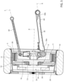
figure 5 is a cross section of the wheel according to a vertical plane including the axis of the wheel, and -
figure 6 is a further cross section of the wheel according to a plane parallel to the plane of the cross section offigure 5 . - In
figure 1 ,reference number 1 is used to indicate, as a whole, a motor vehicle. - The
motor vehicle 1 comprises a body including, in turn, aframe 2 and a bodywork 3 carried by theframe 2 and defining the outer surfaces of themotor vehicle 1. - Furthermore, the
motor vehicle 1 comprises a plurality of wheels orwheel devices 4, only two of them being shown infigure 1 . - The
wheels 4 are coupled to the body or, more precisely, to theframe 2. - The
wheels 4 have similar features, for example except for the dimensions, which is why only one of thewheels 4 will be described more in detail below, provided that the features described for one of thewheels 4 also apply to the others. - The
motor vehicle 1 comprises at least onesuspension 7, which couples one of thewheels 4 to theframe 2. - The
wheel 4 defines the unsprung mass of themotor vehicle 1. - Hence, the
suspension 7 suspends the body or, more precisely, theframe 2 relative to thewheels 4, whereby the body is part of the sprung mass of themotor vehicle 1. - The
wheel 4 comprises arim 5 having, in particular, a tubular geometry. Therim 5 has an axis H (figure 5 ), around which therim 5 extends, thus defining a solid of revolution. - The axis H is transversal relative to a travel direction of the
motor vehicle 1. - The axis H defines a wheel axis, around which the
wheel 4 can rotate. - Furthermore, the
wheel 4 comprises awheel hub unit 9 comprising, in turn, at least three coaxial elements arranged around the axis H and respectively defined by a radiallyinner element 19, a radiallyouter element 16 and abearing 13 supporting the radiallyouter element 16 in a rotary manner around the axis H relative to the radiallyinner element 19. - The
rim 5 is fixed relative to the radiallyouter element 16. - The radially inner element is carried, in a fixed position, by an upright 6 of the
motor vehicle 1. - The
suspension 7 couples the upright 6 to theframe 2, so that theframe 2 is suspended relative to the upright 6, which can be considered part of thewheel 4. - Furthermore, the
wheel 4 preferably comprises anelectric motor 10, in particular with astator 11 that is fixed relative to the upright 6 and arotor 12 that is fixed relative to therim 5. In particular, thestator 11 and therotor 12 are arranged within therim 5, i.e. in the volume internally defined by therim 5. - Practically, the
motor 10 is integrated in thewheel 4, namely thewheel 4 or the assembly consisting of themotor 10 and of thewheel 4 defines an in-wheel motor. - More in particular, the
stator 11 is carried by theelement 19 in a fixed position, whereas therotor 12 is fixed, for example directly, to theelement 16. - The
rotor 12 is configured to magnetically interact with thestator 11, which is what normally happens in the state of the art. - Indeed, the magnetic interaction between the
rotor 12 and thestator 11 allows therotor 12 to rotate relative to thestator 11 around the axis H, thus causing thewheel 4 or, more precisely, therim 5 to rotate relative to the upright 6. - The
motor 10 or, more precisely, thestator 11 compriseselectric windings 28 configured to generate a magnetic field in response to a flow of electric current through thewindings 28. - In detail, the magnetic field interacts with the magnetic flow generated by permanent magnets of the
rotor 12. - The magnetic interaction between the magnetic flow and the magnetic field triggers the relative rotation of the
rotor 12 relative to thestator 11. - The
electric windings 28 can be connected to apower source 31 of themotor vehicle 1, such as for example a battery, so as to be supplied with the electric current. - The supply of power causes the generation of the magnetic field.
- To this aim, the
motor vehicle 1 comprises anelectric wiring 32 to supply power to themotor 10 or, more precisely, to theelectric windings 28. - In particular, the
electric wiring 32 electrically connects thepower source 31 to themotor 10. - The
motor 10 is a mere non-limiting example of an electric member of thewheel 4 that needs to be supplied with power through theelectric wiring 32. - Alternatively or in addition, the
electric wiring 32 could power a control unit or other types of electric members with various functions. - More in general, the electric member is, in turn, an example of a generic device of the
wheel 4 that needs to the supplied with energy in order to operate. - Such a generic device could be supplied, for example, with a fluid or a fluid flow, namely it could be a hydraulic or pneumatic device or the like.
- For example, the generic device could comprise a braking member controllable to brake the
wheel 4, for example a friction braking member (i.e. configured to brake thewheel 4 through friction on the braking member), such as a brake disc or braking pads or brake shoes or the like or a case containing the preceding members of this list. - Like the
motor 10, the generic device can heat up during the operation, so that a conditioning of the device becomes convenient. - Therefore, the
wheel 4 preferably comprises a conditioning member 20 (schematically shown in a conceptual manner), for example a heat exchanger, in thermal contact with the generic device, in this specific case comprising themotor 10. - The
conditioning member 20 permits the conditioning of the generic device or, more precisely, of themotor 10 through the exchange of heat with a fluid flow flowing through or supplied to theconditioning member 20. - Therefore, the
motor vehicle 1 comprises a fluid processing apparatus 21 (schematically shown in a conceptual manner), for example a pump in case of a fluid in the liquid state, to supply the fluid flow to theconditioning member 20. - The fluid of the flow is, in particular, a cooling fluid to remove heat from the
motor 10 or, more in general, from the device heating up during the operation. - Moreover, a further example of the generic device could comprise an actuator 23 (schematically shown in a conceptual manner), for example operable by means of a fluid flow.
- In this case, the
motor vehicle 1 would conveniently comprise a fluid processing apparatus 22 (schematically shown in a conceptual manner), for example a pump in case of a fluid in the liquid state, to supply the fluid flow to theactuator 23. - More in detail, the
actuator 23 is configured to operate abraking device 25 of themotor vehicle 1 configured, in turn, to brake thewheel 4. Here, theactuator 23 operates thebraking device 25 by means of the fluid flow, precisely the one generated by theapparatus 22. - The
braking device 25 preferably comprises a brake disc orfirst friction member 24 carried by therotor 12, in particular at theelement 16, in a fixed position relative to therotor 12. - Furthermore, the
braking device 25 preferably comprises a brake caliper device orsecond friction member 26. The device ormember 26 is configured to cooperate in contact with the brake disc ormember 24 in a selective manner. - The
braking device 25 can be defined, for example, by the first and thesecond friction member - The
second friction member 26 is operable to be brought into contact with thefirst friction member 24, so that a friction is generated between thefirst friction member 24 and thesecond friction member 26. - In other words, the device or
member 26 is operable to grab the brake disc ormember 24, thus exerting a braking action upon therotor 12 through sliding friction, and to release the brake disc ormember 24, thus ceasing to exert the braking action. - In particular, the
actuator 23 is configured to operate thedevice 26 so as to selectively cause the cooperation between thedevice 26 and thebrake disc 24. - Herein, in this specific case, the
braking device 25 is for an emergency use or to create a parking brake or for a use as auxiliary braking device. - Indeed, the
electric motor 10 can be used or controlled as a brake when it works as electric generator. As a matter of fact, themotor 10 is an electric machine suited to work as electrical energy generator. - The
device 26 is carried by theupright 6 or by theelement 19. In other words, thedevice 26 has at least one element that is fixed relative to theupright 6 or to theelement 19. - Furthermore, the
device 26 has at least one movable element carried or controlled by theactuator 23. - The
wheel 4 conveniently comprises awheel trim 29 fixed in front of therim 5, for example through of a shape coupling or by means of threaded members. - The wheel trim 29 is fixed to the
rim 5 in a releasable or removable manner, which means that the separation of the wheel trim 29 from therim 5 can take place without causing damages to the wheel trim 29 or to therim 5. - In other words, the wheel trim 29 is optional and removable.
- The
suspension 7 comprises at least onesuspension arm 30, which is coupled to theframe 2 and to theupright 6 so as to suspend theframe 2 relative to theupright 6 or to thewheel 4. - In particular, the
suspension 7 is an independent suspension. - More in particular, the
suspension 7 has a multi-link layout. - Indeed, besides the
arm 30, thesuspension 7 optionally comprises afurther arm 40. - The
arms motor vehicle 1 or coplanar to the axis H. - The
arm 30 extends between twoends upright 6 and to theframe 2, respectively. - Specifically, the
arm 30 has a triangular shape, as this shape is normally understood in the field of automotive suspensions. Therefore, theend 30b splits up into two branches respectively hinged to theframe 2 around a same hinge axis. - The same considerations substantially also apply to the
optional arm 40, so as to form said multi-link layout, even though thearm 40 is conveniently shaped like a substantially cylindrical rod. - The
multi-link layout 7 is a mere example, since thesuspension 7 could have any layout, such as a MacPherson strut layout, a double wishbone layout, etc.. - According to the invention, the
suspension arm 30 is internally hollow, namely it has or defines one or moreinner cavities 60. - The
inner cavities 60 communicate with the outside of thesuspension arm 30 through a plurality of holes made in thesuspension arm 30. - The
suspension 7 further comprises a plurality ofducts more cavities 60 and through the holes. Each one of theducts - More precisely, at least one, a set or each one of the
ducts inner cavity 60 between aninput hole 50a and anoutput hole 50b. The extension can clearly reach past the correspondingcavity 60 and the holes. I.e. at least one, a set or each one of theducts suspension arm 30. - For example, for greater clarity, the term duct can identify an opening or a tunnel between two holes or also the inner volume of a pipe going through the entire extension of the opening between the holes.
- Each
cavity 60 can coincide with the opening between the two holes or acavity 60 can be meant as a volume inside thearm 30, where one or more ducts, meant as pipes, extend. - In particular, the
input hole 50a is obtained at theend 30a, whereas theoutput hole 50b is obtained at theend 30b, respectively. - The number of
ducts suspension 7 could also comprise only one of theducts - The
ducts - The electric cables are part of the
suspension 7. - Furthermore, the electric cables go through the
respective holes 50a on one side, in particular at theend 30a, and therespective holes 50b on the other side, in particular at theend 30b, thus going through the inner cavity orcavities 60 of thearm 30. - The electric cables are connected to the electric motor 10 o, more in general, to an electric member of the
wheel 4 in order to supply it with power. - In particular, the electric cables are also connected to the
power source 31. - Furthermore, in particular, the electric cables are connected to the
wirings 28. - The electric cables basically define or form part of the
wiring 32. - The
motor 10 is configured to cause thewheel 4 to rotate by means of the electric current supplied through thewiring 32. - The
ducts - More specifically, the
ducts conditioning member 20 and, in particular, also to theapparatus 21. - The
duct 45 preferably is a fluid flow delivery duct, whereby theconditioning member 20 is supplied with a fluid flow through theduct 45. - The
apparatus 21 generates the fluid flow along theduct 45, thus supplying the conditioning member. - Therefore, in this case, the
duct 46 is a fluid flow return duct from theconditioning member 20 to theapparatus 21. The fluid flow returns to theapparatus 21 through theduct 46 after the exchange of heat with themotor 10 or with the generic device heating up during the operation. - The
duct 47 is designed to let through or let through a fluid flow, as well. - More specifically, the
duct 47 is connected to theactuator 23, whereby theactuator 23 is supplied with the fluid flow through theduct 47. - Furthermore, the
actuator 23 is operated through the fluid flow along theduct 47. - The
duct 47 is also connected to theapparatus 22, so that theapparatus 22 generates the fluid flow along theduct 47, thus supplying theactuator 23. - Owing to the above, the advantages of the
suspension 7 according to the invention are evident. - The electric cables and the fluid flows go through the
suspension arm 30, whereby possible pipes on the outside of thearm 30 become completely unnecessary. - The absence of outer pipes has the great advantage that the aerodynamics of the
motor vehicle 1 remain unaffected by the pipes, with an evident increase in aerodynamic efficiency. - Indeed, the typical problems caused by pipes are avoided in this case.
- The increase in aerodynamic efficiency inevitably translates into a general improvement of the overall performances of the
motor vehicle 1. - The
inner cavities 60 do not constitute a structural problem for thesuspension 7, whereby the reliability of themotor vehicle 1 is anyway ensured. - Finally, the
suspension 7 according to the invention can clearly be subjected to changes and variants, which, though, do not go beyond the scope of protection defined by the appended claims. - In particular, each one of the details included in the figures is independent of the other details and is specifically designed to solve specific technical problems in isolation from the other details.
- In particular, the mentioned details include each one of the arrangements of the various components shown relative to the other components.
- More in particular, the shapes and the dimensions shown are mere examples and are not tightly linked to the arrangement of the components.
Claims (12)
- A suspension (7) for a motor vehicle (1), the suspension (7) comprising at least one internally hollow suspension arm (7), so as to define at least one inner cavity (60), characterized by comprising at least one duct (42, 43, 44, 45, 46, 47) extending along the inner cavity (60) between an input hole (50a) of the suspension arm (30) and an output hole (50b) of the suspension arm (30), the duct (42, 43, 44, 45, 46, 47) being designed to allow a fluid flow or an electric wiring (32) to go from the input hole (59a) to the output hole (50b) through the inner cavity (60).
- The suspension according to claim 1, wherein the suspension arm (30) extends along an axis (R) between two hinge ends (30a, 30b) opposite one another and configured to be hinged to an upright (6) and to a frame (2), respectively, of the motor vehicle (1).
- The suspension according to claim 2, wherein the input hole and the output hole (50a, 50b) are obtained on said ends (30a, 30b), respectively, so that the duct (42, 43, 44, 45, 46, 47) extends along said axis (R).
- A motor vehicle (1) comprising an upright (6), a wheel (4) carried by the upright (6) in a rotary manner around a wheel axis (H), a frame (2) and a suspension (7) according to any one of the preceding claims, wherein the suspension arm (30) is coupled to the frame (2) and to the upright (6) so as to suspend the frame (2), and wherein the wheel (4) comprises a device (10, 20, 23) connected to the duct (42, 43, 44, 45, 46, 47) so as to be supplied through the duct (42, 43, 44, 45, 46, 47), in particular with a fluid flow or with power through the electric wiring (32).
- The motor vehicle according to claim 4, wherein the suspension arm (30) extends along an axis (R) transversal to a driving direction of the motor vehicle (1) or coplanar to the wheel axis (H) between two hinge ends (30a, 30b).
- The motor vehicle according to claim 5, wherein the hinge ends (30a, 30b) are hinged to the upright (6) and to the frame (2), respectively.
- The motor vehicle according to any one of the claims from 4 to 6, wherein said device (10, 20, 23) comprises an electric member (10), and wherein the motor vehicle (1) comprises the electric wiring (32) extending through the duct (44, 45, 46) from the input hole (50a) to the output hole (50b) and connected to the electric member (10) so as to supply the electric member (10) with power.
- The motor vehicle according to claim 7, wherein the electric member (10) comprises an electric motor configured to cause the wheel (4) to rotate through the power supplied through the electric wiring (32).
- The motor vehicle according to any one of the claims from 4 to 6, wherein said device (10, 20, 23) comprises a conditioning member (20), for example a heat exchanger, the wheel (4) further comprising a further device (10, 25) in thermal contact with the conditioning member (20) and comprising a fluid processing apparatus (21) configured to generate the fluid flow along the duct (42, 43), thus supplying the conditioning member (20), whereby the conditioning member (20) is configured to condition said further device (10, 25) through exchange of heat with the fluid flow.
- The motor vehicle according to claim 9, wherein said further device (10, 25) comprises an electric motor (10) configured to cause the wheel (4) to rotate and/or a braking member (25) controllable to brake the wheel (4).
- The motor vehicle according to any one of the claims from 4 to 6, wherein said device (10, 20, 23) comprises an actuator (23) operable through the fluid flow along the duct (47), and wherein the motor vehicle (1) comprises a fluid processing apparatus (22) configured to generate the fluid flow along the duct (47), thereby supplying the actuator (23) .
- The motor vehicle according to claim 11, wherein the wheel (4) further comprises a braking device (25) configured to brake the wheel (4), the actuator (23) being configured to operate the braking device (25) through the fluid flow.
Applications Claiming Priority (1)
| Application Number | Priority Date | Filing Date | Title |
|---|---|---|---|
| IT102023000003756A IT202300003756A1 (en) | 2023-03-02 | 2023-03-02 | MOTOR VEHICLE SUSPENSION WITH INTEGRATED DUCTS |
Publications (1)
| Publication Number | Publication Date |
|---|---|
| EP4424531A1 true EP4424531A1 (en) | 2024-09-04 |
Family
ID=86332408
Family Applications (1)
| Application Number | Title | Priority Date | Filing Date |
|---|---|---|---|
| EP24160232.5A Pending EP4424531A1 (en) | 2023-03-02 | 2024-02-28 | Motor vehicle suspension with integrated ducts |
Country Status (3)
| Country | Link |
|---|---|
| US (1) | US20240294045A1 (en) |
| EP (1) | EP4424531A1 (en) |
| IT (1) | IT202300003756A1 (en) |
Families Citing this family (1)
| Publication number | Priority date | Publication date | Assignee | Title |
|---|---|---|---|---|
| GB202102372D0 (en) * | 2021-02-19 | 2021-04-07 | Hughes Thomas | Independent electric drive for low floor vehicles |
Citations (5)
| Publication number | Priority date | Publication date | Assignee | Title |
|---|---|---|---|---|
| EP0701510B1 (en) * | 1993-06-09 | 1997-09-24 | EC Engineering + Consulting Spezialmaschinen GmbH | Suspension for a vehicle wheel |
| US6152433A (en) * | 1997-09-02 | 2000-11-28 | Daimlerchrysler Ag | Motor vehicle axle |
| DE102019109177A1 (en) * | 2019-04-08 | 2020-10-08 | Man Truck & Bus Se | Axle control arm for a wheel suspension |
| CN112158065A (en) * | 2019-10-24 | 2021-01-01 | 中国北方车辆研究所 | Unmanned vehicle in-wheel motor driving control system that traveles |
| US11433724B2 (en) * | 2018-09-12 | 2022-09-06 | Ziehl-Abegg Automotive Gmbh & Co. Kg | Wheel suspension and swing arm for a wheel driven by an electrical or pneumatic motor |
-
2023
- 2023-03-02 IT IT102023000003756A patent/IT202300003756A1/en unknown
-
2024
- 2024-02-27 US US18/588,471 patent/US20240294045A1/en active Pending
- 2024-02-28 EP EP24160232.5A patent/EP4424531A1/en active Pending
Patent Citations (5)
| Publication number | Priority date | Publication date | Assignee | Title |
|---|---|---|---|---|
| EP0701510B1 (en) * | 1993-06-09 | 1997-09-24 | EC Engineering + Consulting Spezialmaschinen GmbH | Suspension for a vehicle wheel |
| US6152433A (en) * | 1997-09-02 | 2000-11-28 | Daimlerchrysler Ag | Motor vehicle axle |
| US11433724B2 (en) * | 2018-09-12 | 2022-09-06 | Ziehl-Abegg Automotive Gmbh & Co. Kg | Wheel suspension and swing arm for a wheel driven by an electrical or pneumatic motor |
| DE102019109177A1 (en) * | 2019-04-08 | 2020-10-08 | Man Truck & Bus Se | Axle control arm for a wheel suspension |
| CN112158065A (en) * | 2019-10-24 | 2021-01-01 | 中国北方车辆研究所 | Unmanned vehicle in-wheel motor driving control system that traveles |
Also Published As
| Publication number | Publication date |
|---|---|
| IT202300003756A1 (en) | 2024-09-02 |
| US20240294045A1 (en) | 2024-09-05 |
Similar Documents
| Publication | Publication Date | Title |
|---|---|---|
| CN102951010B (en) | There is the In-wheel motor of brake | |
| US6942049B2 (en) | In-wheel motor for electric automobiles | |
| US11479107B2 (en) | Selectively attachable and detachable axial hub motor | |
| US7533747B2 (en) | Wheel provided with driving means | |
| EP4424531A1 (en) | Motor vehicle suspension with integrated ducts | |
| US8613345B1 (en) | Quick change combination wheel and brake assembly | |
| CN106627102A (en) | Wheel hub motor driving device | |
| US20040084235A1 (en) | Wheel provided with driving means | |
| JP2013226994A (en) | In-wheel motor drive unit | |
| US20190291797A1 (en) | Customizable chassis module with integrated related functions | |
| CN206436815U (en) | A kind of wheel motor drive device | |
| JP2013014303A (en) | Motor-driven wheel with incorporated swing arm | |
| CN120288017A (en) | An electronic wedge brake system with a spring-loaded actuator | |
| CN113771611A (en) | Hub motor driven rear axle system | |
| CN108016287A (en) | Low-floor modular power vehicle bridge | |
| CN207241414U (en) | A kind of chassis motorized structure using multi-connecting-rod separated suspension | |
| WO2018106929A1 (en) | Customizable chassis module with integrated related functions | |
| CN117396379A (en) | Inverted portal axles for low-floor buses | |
| CN216184449U (en) | Drive assembly | |
| CN119590196B (en) | Front suspension wheel hub motor wheel hub integrated structure, assembly method and automobile | |
| JP2017171251A (en) | In-wheel motor drive device | |
| CN215513940U (en) | Modular unmanned vehicle | |
| CN2760329Y (en) | Electromagnetic brake for automobiles | |
| CN119953106A (en) | A hybrid drive rear axle structure | |
| CN110356220A (en) | A kind of integrated wheel system of Full-numerical-control |
Legal Events
| Date | Code | Title | Description |
|---|---|---|---|
| PUAI | Public reference made under article 153(3) epc to a published international application that has entered the european phase |
Free format text: ORIGINAL CODE: 0009012 |
|
| STAA | Information on the status of an ep patent application or granted ep patent |
Free format text: STATUS: THE APPLICATION HAS BEEN PUBLISHED |
|
| AK | Designated contracting states |
Kind code of ref document: A1 Designated state(s): AL AT BE BG CH CY CZ DE DK EE ES FI FR GB GR HR HU IE IS IT LI LT LU LV MC ME MK MT NL NO PL PT RO RS SE SI SK SM TR |
|
| STAA | Information on the status of an ep patent application or granted ep patent |
Free format text: STATUS: REQUEST FOR EXAMINATION WAS MADE |
|
| 17P | Request for examination filed |
Effective date: 20250227 |