EP4424528A1 - Sensor localization using an assembly line tool - Google Patents
Sensor localization using an assembly line tool Download PDFInfo
- Publication number
- EP4424528A1 EP4424528A1 EP23159149.6A EP23159149A EP4424528A1 EP 4424528 A1 EP4424528 A1 EP 4424528A1 EP 23159149 A EP23159149 A EP 23159149A EP 4424528 A1 EP4424528 A1 EP 4424528A1
- Authority
- EP
- European Patent Office
- Prior art keywords
- vehicle
- assembly line
- tool
- tyre
- sensor
- Prior art date
- Legal status (The legal status is an assumption and is not a legal conclusion. Google has not performed a legal analysis and makes no representation as to the accuracy of the status listed.)
- Pending
Links
Images


Classifications
-
- B—PERFORMING OPERATIONS; TRANSPORTING
- B60—VEHICLES IN GENERAL
- B60C—VEHICLE TYRES; TYRE INFLATION; TYRE CHANGING; CONNECTING VALVES TO INFLATABLE ELASTIC BODIES IN GENERAL; DEVICES OR ARRANGEMENTS RELATED TO TYRES
- B60C23/00—Devices for measuring, signalling, controlling, or distributing tyre pressure or temperature, specially adapted for mounting on vehicles; Arrangement of tyre inflating devices on vehicles, e.g. of pumps or of tanks; Tyre cooling arrangements
- B60C23/02—Signalling devices actuated by tyre pressure
- B60C23/04—Signalling devices actuated by tyre pressure mounted on the wheel or tyre
- B60C23/0408—Signalling devices actuated by tyre pressure mounted on the wheel or tyre transmitting the signals by non-mechanical means from the wheel or tyre to a vehicle body mounted receiver
- B60C23/0479—Communicating with external units being not part of the vehicle, e.g. tools for diagnostic, mobile phones, electronic keys or service stations
-
- G—PHYSICS
- G07—CHECKING-DEVICES
- G07C—TIME OR ATTENDANCE REGISTERS; REGISTERING OR INDICATING THE WORKING OF MACHINES; GENERATING RANDOM NUMBERS; VOTING OR LOTTERY APPARATUS; ARRANGEMENTS, SYSTEMS OR APPARATUS FOR CHECKING NOT PROVIDED FOR ELSEWHERE
- G07C5/00—Registering or indicating the working of vehicles
- G07C5/08—Registering or indicating performance data other than driving, working, idle, or waiting time, with or without registering driving, working, idle or waiting time
- G07C5/0808—Diagnosing performance data
-
- B—PERFORMING OPERATIONS; TRANSPORTING
- B60—VEHICLES IN GENERAL
- B60B—VEHICLE WHEELS; CASTORS; AXLES FOR WHEELS OR CASTORS; INCREASING WHEEL ADHESION
- B60B29/00—Apparatus or tools for mounting or dismounting wheels
- B60B29/003—Wrenches, e.g. of the ratchet type
- B60B29/006—Wrenches, e.g. of the ratchet type with electric or pneumatic drive
-
- B—PERFORMING OPERATIONS; TRANSPORTING
- B60—VEHICLES IN GENERAL
- B60C—VEHICLE TYRES; TYRE INFLATION; TYRE CHANGING; CONNECTING VALVES TO INFLATABLE ELASTIC BODIES IN GENERAL; DEVICES OR ARRANGEMENTS RELATED TO TYRES
- B60C23/00—Devices for measuring, signalling, controlling, or distributing tyre pressure or temperature, specially adapted for mounting on vehicles; Arrangement of tyre inflating devices on vehicles, e.g. of pumps or of tanks; Tyre cooling arrangements
- B60C23/02—Signalling devices actuated by tyre pressure
- B60C23/04—Signalling devices actuated by tyre pressure mounted on the wheel or tyre
- B60C23/0408—Signalling devices actuated by tyre pressure mounted on the wheel or tyre transmitting the signals by non-mechanical means from the wheel or tyre to a vehicle body mounted receiver
- B60C23/0471—System initialisation, e.g. upload or calibration of operating parameters
- B60C23/0472—System initialisation, e.g. upload or calibration of operating parameters to manually allocate ID codes or mounting positions, e.g. by service technicians
-
- B—PERFORMING OPERATIONS; TRANSPORTING
- B60—VEHICLES IN GENERAL
- B60C—VEHICLE TYRES; TYRE INFLATION; TYRE CHANGING; CONNECTING VALVES TO INFLATABLE ELASTIC BODIES IN GENERAL; DEVICES OR ARRANGEMENTS RELATED TO TYRES
- B60C23/00—Devices for measuring, signalling, controlling, or distributing tyre pressure or temperature, specially adapted for mounting on vehicles; Arrangement of tyre inflating devices on vehicles, e.g. of pumps or of tanks; Tyre cooling arrangements
- B60C23/02—Signalling devices actuated by tyre pressure
- B60C23/04—Signalling devices actuated by tyre pressure mounted on the wheel or tyre
- B60C23/0408—Signalling devices actuated by tyre pressure mounted on the wheel or tyre transmitting the signals by non-mechanical means from the wheel or tyre to a vehicle body mounted receiver
- B60C23/0481—System diagnostic, e.g. monitoring battery voltage, detecting hardware detachments or identifying wireless transmission failures
-
- B—PERFORMING OPERATIONS; TRANSPORTING
- B60—VEHICLES IN GENERAL
- B60C—VEHICLE TYRES; TYRE INFLATION; TYRE CHANGING; CONNECTING VALVES TO INFLATABLE ELASTIC BODIES IN GENERAL; DEVICES OR ARRANGEMENTS RELATED TO TYRES
- B60C25/00—Apparatus or tools adapted for mounting, removing or inspecting tyres
- B60C25/01—Apparatus or tools adapted for mounting, removing or inspecting tyres for removing tyres from or mounting tyres on wheels
- B60C25/05—Machines
- B60C25/0515—Automated devices, e.g. mounting robots
-
- G—PHYSICS
- G05—CONTROLLING; REGULATING
- G05B—CONTROL OR REGULATING SYSTEMS IN GENERAL; FUNCTIONAL ELEMENTS OF SUCH SYSTEMS; MONITORING OR TESTING ARRANGEMENTS FOR SUCH SYSTEMS OR ELEMENTS
- G05B19/00—Program-control systems
- G05B19/02—Program-control systems electric
- G05B19/418—Total factory control, i.e. centrally controlling a plurality of machines, e.g. direct or distributed numerical control [DNC], flexible manufacturing systems [FMS], integrated manufacturing systems [IMS] or computer integrated manufacturing [CIM]
- G05B19/41875—Total factory control, i.e. centrally controlling a plurality of machines, e.g. direct or distributed numerical control [DNC], flexible manufacturing systems [FMS], integrated manufacturing systems [IMS] or computer integrated manufacturing [CIM] characterised by quality surveillance of production
-
- B—PERFORMING OPERATIONS; TRANSPORTING
- B62—LAND VEHICLES FOR TRAVELLING OTHERWISE THAN ON RAILS
- B62D—MOTOR VEHICLES; TRAILERS
- B62D65/00—Designing, manufacturing, e.g. assembling, facilitating disassembly, or structurally modifying motor vehicles or trailers, not otherwise provided for
- B62D65/005—Inspection and final control devices
-
- B—PERFORMING OPERATIONS; TRANSPORTING
- B62—LAND VEHICLES FOR TRAVELLING OTHERWISE THAN ON RAILS
- B62D—MOTOR VEHICLES; TRAILERS
- B62D65/00—Designing, manufacturing, e.g. assembling, facilitating disassembly, or structurally modifying motor vehicles or trailers, not otherwise provided for
- B62D65/02—Joining sub-units or components to, or positioning sub-units or components with respect to, body shell or other sub-units or components
- B62D65/12—Joining sub-units or components to, or positioning sub-units or components with respect to, body shell or other sub-units or components the sub-units or components being suspensions, brakes or wheel units
-
- G—PHYSICS
- G05—CONTROLLING; REGULATING
- G05B—CONTROL OR REGULATING SYSTEMS IN GENERAL; FUNCTIONAL ELEMENTS OF SUCH SYSTEMS; MONITORING OR TESTING ARRANGEMENTS FOR SUCH SYSTEMS OR ELEMENTS
- G05B2219/00—Program-control systems
- G05B2219/30—Nc systems
- G05B2219/45—Nc applications
- G05B2219/45018—Car, auto, vehicle
Definitions
- the disclosure relates generally to assembly of vehicles.
- the disclosure relates to sensor localisation using an assembly line tool.
- the disclosure can be applied to heavy-duty vehicles, such as trucks, buses, and construction equipment, among other vehicle types.
- heavy-duty vehicles such as trucks, buses, and construction equipment, among other vehicle types.
- Vehicles such as heavy-duty vehicles, might have integrated wireless sensors and gateways/receivers designed to read such sensors and forward data to electronic control units (ECUs).
- ECUs electronice control units
- gateways/receivers require mappings, in terms of reading an identification (ID) of a specific sensor and its location on vehicle.
- ID identification
- TPM tyre Pressure Monitoring
- the ID and the location of sensors are read manually by scanning each tyre (e.g. indirectly by optical scanning of labels, QR codes or directly by activation of the sensor).
- the TPM ECU might have an auto location functionality where the location of each sensor is determined by the ECU.
- the auto location functionality is only deployed during vehicle movement, i.e. when the wheel is rolling.
- this method requires other sensor data such as a wheel speed reading from each vehicle axle provided by the Electronic Brake System (EBS) ECU.
- EBS Electronic Brake System
- Auto location of a sensor may take up to 10 minutes of continuous driving at different speeds. For an assembly line, it is important to get all diagnostics and parameter settings done before the vehicle leaves the line.
- mapping sensor ID with location on the vehicle onto which it is assembled.
- a diagnostic system for verifying functionality and performing mapping of one or more wireless sensors in or on a wheel of a heavy-duty vehicle on an assembly line comprises: one or more assembly-line tools provided along the assembly line, each assembly-line tool comprising one or more antenna systems arranged to interrogate one or more wireless sensors integrated into or on a wheel of the vehicle, wherein each assembly-line tool is arranged in use to:
- the assembly line tool comprises a spindle tool configured to bolt vehicle wheels to a vehicle chassis or a wheel lift configured to lifting vehicle wheels onto an axle of a vehicle chassis.
- a technical benefit may include the possibility to use a variety of tools to perform the mapping during various stages of assembly. In this way, mapping can take place where it is most effective.
- the assembly line tool is configured to interrogate one or more axle position sensors on a vehicle on the assembly line.
- a technical benefit may include to easily obtain data for where the wireless sensor is located on the vehicle chassis.
- Axle position sensors are for instance integrated into the wheel hubs of the chassis of the vehicle.
- the assembly line tool is configured to interrogate one or more axle position sensors, and store data that pairs the axle position of the spindle-tool with the sensors detected at that location.
- a technical benefit may include effective mapping of a specific sensor with a specific axle of the vehicle chassis.
- the assembly line tool is further configured to activate a diagnostic mode of a tyre pressure and/or tyre temperature sensor system of the vehicle on the vehicle assembly line.
- a technical benefit may include to check the functionality of the sensor at the same time or close in time with the mapping of the sensor.
- one of the antenna systems provided on the assembly line tool comprises a plurality of low frequency antennas spaced around the assembly line tool so as to provide at least one antenna at a location sufficiently close to a tyre pressure and temperature sensor to perform a reading of data provided by the tyre pressure and sensor.
- a technical benefit may include that the tool will be able to read the sensor no matter its orientation if sufficiently close enough to the wheel.
- the data provided by the tyre pressure/temperature sensor includes a TPS identifier (TPS_ID).
- TPS_ID TPS identifier
- the assembly line tool is configured to read one or more RFID tags located in a vehicle tyre or wheel rim.
- a technical benefit may include easy access to the RFID information of the tyre for future use.
- the assembly line tool may also be configured to read the axle location/position info from an axle position sensor.
- the assembly line tool configures each TPS_ID to be associated with a vehicle tyre RFID and/or a vehicle chassis ID.
- a technical benefit may include quick pairing of the TPS_ID with the tyre RFID or vehicle chassis ID.
- the assembly line tool may also be configured to associate the axle location/position info from an axle position sensor with the TPS_ID.
- the assembly line tool stores data that pairs each TPS_ID with a vehicle tyre RFID and/or with a vehicle chassis ID.
- a technical benefit may include that only the tyre RFID is needed to which sensor or sensors are present in the tyre.
- an assembly-line tool for verifying functionality and performing mapping of one or more wireless sensors in a heavy-duty vehicle on an assembly line at assembly time, the tool comprising: one or more antenna systems arranged to interrogate one or more wireless sensors integrated into or on the vehicle, wherein the assembly-line tool is configured in use to:
- the assembly line tool comprises a spindle tool configured to bolt vehicle wheels to a vehicle chassis or a wheel lift configured to lifting vehicle wheels onto an axle of a vehicle chassis and interrogate one or more axle position sensors on a vehicle wheel of a vehicle on the assembly line.
- a technical benefit may include A technical benefit may include the possibility to use a variety of tools to perform the mapping during various stages of assembly. In this way, mapping can take place where it is most effective.
- the assembly line tool is configured to interrogate one or more axle position sensors on a vehicle wheel of a vehicle on the assembly line, and stores data which pairs the axle position of the spindle-tool with the sensors (TPS/RFID) detected at that location.
- TPS/RFID sensors
- the assembly line tool is further configured to activate a diagnostic mode of a tyre pressure and/or tyre temperature sensor system of the vehicle on the vehicle assembly line.
- a technical benefit may include to check the functionality of the sensor at the same time or close in time with the mapping of the sensor.
- one of the antenna systems provided on the spindle tool comprises a plurality of low frequency antennas spaced around the spindle tool so as to provide at least one antenna at a location sufficiently close to a tyre pressure and temperature sensor to enable the spindle tool to:
- FIG. 1 is an exemplary overview of a manufacturing line for heavy-duty vehicles.
- an assembly line 100 can be seen with vehicle 102a, 102b, 102c in different stages of completion.
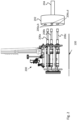
- FIG. 2 is an exemplary overview of an assembly-line tool for verifying functionality and performing mapping of one or more wireless sensors in a heavy-duty vehicle on an assembly line at assembly time.
- a diagnostic system 200 is arranged on an assembly line tool arranged to interact with a wheel 202.
- the wheel 202 is arranged on an axle 204 of a vehicle 102 to be assembled or arranged to be mounted onto the axle 204.
- the wheel comprises a number of tyre sensors 206a,b,c,d; for instance temperature and pressure sensors (TPS).
- TPS temperature and pressure sensors
- the assembly line tool is in the present example a spindle tool 208 arranged to tighten bolts of the wheel 202.
- the spindle tool is also called a nut runner. Spindle tools or nut runners may have several spindles, e.g. from one to five.
- the assembly line tool can also be a wheel lift configured to lift a vehicle wheel onto the axle 204.
- an antenna or an array of antennas are integrated and configured to automatically read data from one or more wireless sensors provided on or in the vehicles being assembled.
- the wireless sensor is a tyre sensor.
- the vehicles under assembly have integrated gateways that provide data to the vehicles sensor ECU.
- mapping and subsequent diagnostics can be performed more quickly. This improves the way that such sensors can be mapped for vehicle diagnostics by locating and verifying the positions and identities of wireless sensors using an antenna or antenna array located in an assembly line environment.
- locating is meant finding the location of the sensor on the vehicle chassis, i.e. the location on which axle that the specific sensor ID is assembled.
- Fig. 3 is a flowchart of an exemplary method 300 for pairing one or more tyre sensors with a tyre ID of a tyre on a vehicle whilst the vehicle is on its assembly line.
- the method 300 may comprise the following actions, steps or operations.
- Action 302. A wireless sensor is located and the functions of the sensor are verified.
- Action 304. The sensor is interrogated to read the tyre pressure and temperature (TPS) values as well as the identification information of the sensor (TPS_ID).
- Action 308. The tyre RFID is read and the TPS_ID and the tyre RFID is paired. Further, an axle position sensor is interrogated and is paired with the tyre sensor ID (TPS_ID) with its location on the vehicle chassis. Thus, two pairings are made: one pairing is to pair the tyre sensor ID to the RFID of that specific tyre and another pairing is to pair the sensor ID to the axle position on a chassis ID.
- Action 310. The pairing data of the tyre RFID and the TPS_ID and the tyre RFID and the chassis ID is stored, or sent for storage on another apparatus.
- Action 312. The stored pairing data is sent to a diagnostic system.
- more than one sensor value and identification can be read by interrogating a further sensor. If this is the case, all sensor identifications are paired with the tyre RFID, stored, or sent for storage, and thereafter sent to the diagnostic system.
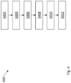
- Fig. 4 is a flowchart of an exemplary method for verifying functionality and performing mapping of one or more wireless sensors in or on a wheel of a heavy-duty vehicle on an assembly line.
- the method 400 may comprise the following actions, steps or operations.
- Action S402. The wireless tyre sensor is activated and set into diagnostic mode using an assembly line tool.
- Action 5404. The wireless tyre sensor is interrogated to read sensor identification and diagnostic data.
- the sensor identification and diagnostic data of the wireless tyre sensor is paired with the tyre RFID. Also, the sensor identification and diagnostic data is paired with a vehicle chassis ID.
- the sensor(s) are mapped using the obtained pairing data.
- the sensor mapping data is sent to the appropriate vehicle electronic control unit.
- Fig. 5 is an exemplary overview of a diagnostic system 500 for verifying functionality and performing mapping of one or more wireless sensors in or on a wheel of a heavy-duty vehicle on an assembly line.
- the diagnostic system 500 comprises a controller 502 configured to connect the diagnostic system to the spindle tool or wheel lift of the assembly line arrangement 200.
- the system 500 further comprises a memory 504 , computer code 506 , one or more processor(s) or processing circuitry 508 , and a data communications transceiver arrangement 510 connected to an antenna 512.
- the computer code when loaded from memory 504 and executed by the one or more processors or processing circuitry 508 , causes the diagnostic system 500 to wirelessly connect to the spindle tool or wheel lift and perform the actions, steps or operations of the methods described above.
- FIG. 6 is a schematic diagram of an exemplary computer system 600 for implementing examples disclosed herein.
- the computer system 600 is adapted to execute instructions from a computer-readable medium to perform these and/or any of the functions or processing described herein.
- the computer system 600 may be connected (e.g., networked) to other machines in a LAN, an intranet, an extranet, or the Internet. While only a single device is illustrated, the computer system 600 may include any collection of devices that individually or jointly execute a set (or multiple sets) of instructions to perform any one or more of the methodologies discussed herein.
- any reference in the disclosure and/or claims to a computer system, computing system, computer device, computing device, control system, control unit, electronic control unit (ECU), processor device, etc. includes reference to one or more such devices to individually or jointly execute a set (or multiple sets) of instructions to perform any one or more of the methodologies discussed herein.
- control system may include a single control unit or a plurality of control units connected or otherwise communicatively coupled to each other, such that any performed function may be distributed between the control units as desired.
- such devices may communicate with each other or other devices by various system architectures, such as directly or via a Controller Area Network (CAN) bus, etc.
- CAN Controller Area Network
- the computer system 600 may comprise at least one computing device or electronic device capable of including firmware, hardware, and/or executing software instructions to implement the functionality described herein.
- the computer system 600 may include a processor device 602 (may also be referred to as a control unit), a memory 604, and a system bus 606.
- the computer system 600 may include at least one computing device having the processor device 602.
- the system bus 606 provides an interface for system components including, but not limited to, the memory 604 and the processor device 602.
- the processor device 602 may include any number of hardware components for conducting data or signal processing or for executing computer code stored in memory 604.
- the processor device 602 may, for example, include a general-purpose processor, an application specific processor, a Digital Signal Processor (DSP), an Application Specific Integrated Circuit (ASIC), a Field Programmable Gate Array (FPGA), a circuit containing processing components, a group of distributed processing components, a group of distributed computers configured for processing, or other programmable logic device, discrete gate or transistor logic, discrete hardware components, or any combination thereof designed to perform the functions described herein.
- the processor device may further include computer executable code that controls operation of the programmable device.
- the system bus 606 may be any of several types of bus structures that may further interconnect to a memory bus (with or without a memory controller), a peripheral bus, and/or a local bus using any of a variety of bus architectures.
- the memory 604 may be one or more devices for storing data and/or computer code for completing or facilitating methods described herein.
- the memory 604 may include database components, object code components, script components, or other types of information structure for supporting the various activities herein. Any distributed or local memory device may be utilized with the systems and methods of this description.
- the memory 604 may be communicably connected to the processor device 602 (e.g., via a circuit or any other wired, wireless, or network connection) and may include computer code for executing one or more processes described herein.
- the memory 604 may include non-volatile memory 605 (e.g., read-only memory (ROM), erasable programmable read-only memory (EPROM), electrically erasable programmable read-only memory (EEPROM), etc.), and volatile memory 610 (e.g., random-access memory (RAM)), or any other medium which can be used to carry or store desired program code in the form of machine-executable instructions or data structures and which can be accessed by a computer or other machine with a processor device 602.
- a basic input/output system (BIOS) 612 may be stored in the non-volatile memory 605 and can include the basic routines that help to transfer information between elements within the computer system 600.
- BIOS basic input/output system
- the computer system 600 may further include or be coupled to a non-transitory computer-readable storage medium such as the storage device 614, which may comprise, for example, an internal or external hard disk drive (HDD) (e.g., enhanced integrated drive electronics (EIDE) or serial advanced technology attachment (SATA)), HDD (e.g., EIDE or SATA) for storage, flash memory, or the like.
- HDD enhanced integrated drive electronics
- SATA serial advanced technology attachment
- the storage device 614 and other drives associated with computer-readable media and computer-usable media may provide non-volatile storage of data, data structures, computer-executable instructions, and the like.
- a number of modules can be implemented as software and/or hard-coded in circuitry to implement the functionality described herein in whole or in part.
- the modules may be stored in the storage device 614 and/or in the volatile memory 610, which may include an operating system 616 and/or one or more program modules 615. All or a portion of the examples disclosed herein may be implemented as a computer program product 620 stored on a transitory or non-transitory computer-usable or computer-readable storage medium (e.g., single medium or multiple media), such as the storage device 614, which includes complex programming instructions (e.g., complex computer-readable program code) to cause the processor device 602 to carry out the steps described herein.
- the computer-readable program code can comprise software instructions for implementing the functionality of the examples described herein when executed by the processor device 602.
- the processor device 602 may serve as a controller or control system for the computer system 600 that is to implement the functionality described herein.
- the computer system 600 also may include an input device interface 622 (e.g., input device interface and/or output device interface).
- the input device interface 622 may be configured to receive input and selections to be communicated to the computer system 600 when executing instructions, such as from a keyboard, mouse, touch-sensitive surface, etc.
- Such input devices may be connected to the processor device 602 through the input device interface 622 coupled to the system bus 606 but can be connected through other interfaces such as a parallel port, an Institute of Electrical and Electronic Engineers (IEEE) 1394 serial port, a Universal Serial Bus (USB) port, an IR interface, and the like.
- IEEE Institute of Electrical and Electronic Engineers
- USB Universal Serial Bus
- the computer system 600 may include an output device interface 624 configured to forward output, such as to a display, a video display unit (e.g., a liquid crystal display (LCD) or a cathode ray tube (CRT)).
- a video display unit e.g., a liquid crystal display (LCD) or a cathode ray tube (CRT)
- the computer system 600 may also include a communications interface 626 suitable for communicating with a network as appropriate or desired.
- Example 1 A method for pairing one or more tyre sensors with a tyre RDID of a tyre on a vehicle and a vehicle chassis ID during assembly of vehicle, wherein the method comprises:
- the method of example 1 may comprise:
- Example 2 A method for verifying functionality and performing mapping of a wireless tyre sensor by a diagnostic system, wherein the method comprises:
- control system comprising one or more control units configured to perform the methods according to any of the examples described above is also provided.
- Relative terms such as “below” or “above” or “upper” or “lower” or “horizontal” or “vertical” may be used herein to describe a relationship of one element to another element as illustrated in the Figures. It will be understood that these terms and those discussed above are intended to encompass different orientations of the device in addition to the orientation depicted in the Figures. It will be understood that when an element is referred to as being “connected” or “coupled” to another element, it can be directly connected or coupled to the other element, or intervening elements may be present. In contrast, when an element is referred to as being “directly connected” or “directly coupled” to another element, there are no intervening elements present.
Landscapes
- Engineering & Computer Science (AREA)
- Mechanical Engineering (AREA)
- Computer Networks & Wireless Communication (AREA)
- Physics & Mathematics (AREA)
- General Physics & Mathematics (AREA)
- General Engineering & Computer Science (AREA)
- Manufacturing & Machinery (AREA)
- Quality & Reliability (AREA)
- Automation & Control Theory (AREA)
- Robotics (AREA)
- Arrangements For Transmission Of Measured Signals (AREA)
Abstract
The disclosure relates to a diagnostic system (200) for verifying functionality and performing mapping of a wireless sensor (206) in/on a wheel of a heavy-duty vehicle (102a) on an assembly line (100), the system (200) comprising:an assembly-line tool (208) provided along the assembly line, each tool comprising one or more antenna systems arranged to interrogate a wireless sensor (206) integrated into/on a wheel (202) of the vehicle (102a), each tool is arranged in use to:automatically locate on the vehicle (102a) and verify a function of the sensor (206); andinterrogate the sensor (206) to perform a wireless sensor reading; andpair sensor reading data with a tyre identifier,pair sensor reading data with a vehicle chassis ID,wherein the diagnostic system (200) maps the sensor (206) using sensor readings andprovides mapping information for the sensor (206) to a gateway/receiver of an electronic control unit of the vehicle.
Description
- The disclosure relates generally to assembly of vehicles. In particular aspects, the disclosure relates to sensor localisation using an assembly line tool. The disclosure can be applied to heavy-duty vehicles, such as trucks, buses, and construction equipment, among other vehicle types. Although the disclosure may be described with respect to a particular vehicle, the disclosure is not restricted to any particular vehicle.
- Vehicles, such as heavy-duty vehicles, might have integrated wireless sensors and gateways/receivers designed to read such sensors and forward data to electronic control units (ECUs). During factory assembly of the vehicle, such gateways/receivers require mappings, in terms of reading an identification (ID) of a specific sensor and its location on vehicle.
- Example of such a system of integrated wireless sensors and gateways/receivers is the tyre Pressure Monitoring (TPM) ECU designed to read sensors integrated in tyres. Each sensor has a unique ID. The TPM ECU needs to be informed of all IDs of the tyre sensors and their locations on the vehicle chassis.
- Today, the ID and the location of sensors are read manually by scanning each tyre (e.g. indirectly by optical scanning of labels, QR codes or directly by activation of the sensor). Alternatively, the TPM ECU might have an auto location functionality where the location of each sensor is determined by the ECU. However, the auto location functionality is only deployed during vehicle movement, i.e. when the wheel is rolling. Additionally, this method requires other sensor data such as a wheel speed reading from each vehicle axle provided by the Electronic Brake System (EBS) ECU. Auto location of a sensor may take up to 10 minutes of continuous driving at different speeds. For an assembly line, it is important to get all diagnostics and parameter settings done before the vehicle leaves the line.
- There is thus a need for an improved way of mapping sensor ID with location on the vehicle onto which it is assembled.
- According to a first aspect of the disclosure, a diagnostic system for verifying functionality and performing mapping of one or more wireless sensors in or on a wheel of a heavy-duty vehicle on an assembly line, comprises:
one or more assembly-line tools provided along the assembly line, each assembly-line tool comprising one or more antenna systems arranged to interrogate one or more wireless sensors integrated into or on a wheel of the vehicle, wherein each assembly-line tool is arranged in use to: - automatically locate on the vehicle and verify a function of the one or more wireless sensors; and
- interrogate at least one of the one or more wireless sensors to perform a wireless sensor reading; and
- pair sensor reading data with a tyre identifier,
- pair sensor reading data with a vehicle chassis ID,
- wherein the diagnostic system maps one or more sensors using wireless sensor readings and provides mapping information for the one or more sensors to a gateway/receiver of an electronic control unit of the vehicle. The first aspect of the disclosure may seek to simplify pairing and mapping of vehicle sensors with the vehicle's electronic control unit (ECU). A technical benefit may include reducing the time needed to pair and map sensors of a vehicle tyre with the vehicle on which it is assembled. With mapping is meant that one or more integrated gateways of the vehicle under assembly that provides data to the vehicle's sensor ECU is supplied with this info.
- In some examples, including in at least one preferred example, optionally the assembly line tool comprises a spindle tool configured to bolt vehicle wheels to a vehicle chassis or a wheel lift configured to lifting vehicle wheels onto an axle of a vehicle chassis. A technical benefit may include the possibility to use a variety of tools to perform the mapping during various stages of assembly. In this way, mapping can take place where it is most effective.
- In some examples, including in at least one preferred example, optionally the assembly line tool is configured to interrogate one or more axle position sensors on a vehicle on the assembly line. A technical benefit may include to easily obtain data for where the wireless sensor is located on the vehicle chassis. Axle position sensors are for instance integrated into the wheel hubs of the chassis of the vehicle.
- In some examples, including in at least one preferred example, optionally the assembly line tool is configured to interrogate one or more axle position sensors, and store data that pairs the axle position of the spindle-tool with the sensors detected at that location. A technical benefit may include effective mapping of a specific sensor with a specific axle of the vehicle chassis.
- In some examples, including in at least one preferred example, optionally the assembly line tool is further configured to activate a diagnostic mode of a tyre pressure and/or tyre temperature sensor system of the vehicle on the vehicle assembly line. A technical benefit may include to check the functionality of the sensor at the same time or close in time with the mapping of the sensor.
- In some examples, including in at least one preferred example, optionally one of the antenna systems provided on the assembly line tool comprises a plurality of low frequency antennas spaced around the assembly line tool so as to provide at least one antenna at a location sufficiently close to a tyre pressure and temperature sensor to perform a reading of data provided by the tyre pressure and sensor. A technical benefit may include that the tool will be able to read the sensor no matter its orientation if sufficiently close enough to the wheel.
- In some examples, including in at least one preferred example, optionally the data provided by the tyre pressure/temperature sensor (TPS) includes a TPS identifier (TPS_ID). A technical benefit may include easy identification of the sensor.
- In some examples, including in at least one preferred example, optionally the assembly line tool is configured to read one or more RFID tags located in a vehicle tyre or wheel rim. A technical benefit may include easy access to the RFID information of the tyre for future use. The assembly line tool may also be configured to read the axle location/position info from an axle position sensor.
- In some examples, including in at least one preferred example, optionally the assembly line tool configures each TPS_ID to be associated with a vehicle tyre RFID and/or a vehicle chassis ID. A technical benefit may include quick pairing of the TPS_ID with the tyre RFID or vehicle chassis ID. The assembly line tool may also be configured to associate the axle location/position info from an axle position sensor with the TPS_ID.
- In some examples, including in at least one preferred example, optionally the assembly line tool stores data that pairs each TPS_ID with a vehicle tyre RFID and/or with a vehicle chassis ID. A technical benefit may include that only the tyre RFID is needed to which sensor or sensors are present in the tyre.
- According to a second aspect of the disclosure, an assembly-line tool for verifying functionality and performing mapping of one or more wireless sensors in a heavy-duty vehicle on an assembly line at assembly time, the tool comprising: one or more antenna systems arranged to interrogate one or more wireless sensors integrated into or on the vehicle, wherein the assembly-line tool is configured in use to:
- automatically locate and verify a function of the one or more wireless sensors; and
- interrogate at least one of the one or more wireless sensors to perform a wireless sensor reading;
- pair sensor reading data with tyre identifier; and
- pair sensor reading data with a vehicle chassis ID,
- send the wireless sensor reading to a diagnostic system configured to determine mapping information for the one or more sensors. The second aspect of the disclosure may seek to reduce the time needed for mapping tyre sensors to the correct location in a vehicle. A technical benefit may include to provide a tool that will speed up the identification and pairing of tyre sensor information with the vehicle chassis identification during assembly.
- In some examples, including in at least one preferred example, optionally the assembly line tool comprises a spindle tool configured to bolt vehicle wheels to a vehicle chassis or a wheel lift configured to lifting vehicle wheels onto an axle of a vehicle chassis and interrogate one or more axle position sensors on a vehicle wheel of a vehicle on the assembly line. A technical benefit may include A technical benefit may include the possibility to use a variety of tools to perform the mapping during various stages of assembly. In this way, mapping can take place where it is most effective.
- In some examples, including in at least one preferred example, optionally the assembly line tool is configured to interrogate one or more axle position sensors on a vehicle wheel of a vehicle on the assembly line, and stores data which pairs the axle position of the spindle-tool with the sensors (TPS/RFID) detected at that location. A technical benefit may include quick access to the axle position for pairing with the sensor identification.
- In some examples, including in at least one preferred example, optionally the assembly line tool is further configured to activate a diagnostic mode of a tyre pressure and/or tyre temperature sensor system of the vehicle on the vehicle assembly line. A technical benefit may include to check the functionality of the sensor at the same time or close in time with the mapping of the sensor.
- In some examples, including in at least one preferred example, optionally one of the antenna systems provided on the spindle tool comprises a plurality of low frequency antennas spaced around the spindle tool so as to provide at least one antenna at a location sufficiently close to a tyre pressure and temperature sensor to enable the spindle tool to:
- perform a reading of data provided by the tyre pressure and sensor, wherein the data provided by the tyre pressure/temperature sensor (TPS) includes a TPS identifier, TPS_ID;
- read one or more RFID tags located in a vehicle tyre or wheel rim;
- associate each TPS_ID with a vehicle tyre RFID and/or a vehicle chassis ID; and
- store, or send for storage on another apparatus, data pairing each TPS_ID with a vehicle tyre RFID and/or with a vehicle chassis ID. A technical benefit may include A technical benefit may include that the spindle tool will be able to read the wireless sensor no matter its orientation if sufficiently close to the wheel.
- The disclosed aspects, examples (including any preferred examples), and/or accompanying claims may be suitably combined with each other as would be apparent to anyone of ordinary skill in the art. Additional features and advantages are disclosed in the following description, claims, and drawings, and in part will be readily apparent therefrom to those skilled in the art or recognized by practicing the disclosure as described herein.
- Examples are described in more detail below with reference to the appended drawings.
-
FIG. 1 is an exemplary overview of a manufacturing line for heavy-duty vehicle. -
FIG. 2 is an exemplary overview of an assembly-line tool for verifying functionality and performing mapping of one or more wireless sensors in a heavy-duty vehicle on an assembly line at assembly time. -
Fig. 3 is a flowchart of an exemplary method for pairing one or more tyre sensors with a tyre ID of a tyre on a vehicle whilst the vehicle is on its assembly line. -
Fig. 4 is a flowchart of an exemplary method for verifying functionality and performing mapping of one or more wireless sensors in or on a wheel of a heavy-duty vehicle on an assembly line. -
Fig. 5 is an exemplary overview of a diagnostic system for verifying functionality and performing mapping of one or more wireless sensors in or on a wheel of a heavy-duty vehicle on an assembly line. - The detailed description set forth below provides information and examples of the disclosed technology with sufficient detail to enable those skilled in the art to practice the disclosure.
-
FIG. 1 is an exemplary overview of a manufacturing line for heavy-duty vehicles. Infigure 1 , anassembly line 100 can be seen withvehicle -
FIG. 2 is an exemplary overview of an assembly-line tool for verifying functionality and performing mapping of one or more wireless sensors in a heavy-duty vehicle on an assembly line at assembly time. Adiagnostic system 200 is arranged on an assembly line tool arranged to interact with awheel 202. Thewheel 202 is arranged on anaxle 204 of a vehicle 102 to be assembled or arranged to be mounted onto theaxle 204. The wheel comprises a number oftyre sensors 206a,b,c,d; for instance temperature and pressure sensors (TPS). The assembly line tool is in the present example aspindle tool 208 arranged to tighten bolts of thewheel 202. The spindle tool is also called a nut runner. Spindle tools or nut runners may have several spindles, e.g. from one to five. The assembly line tool can also be a wheel lift configured to lift a vehicle wheel onto theaxle 204. - In the
spindle tool 208, an antenna or an array of antennas are integrated and configured to automatically read data from one or more wireless sensors provided on or in the vehicles being assembled. In this example, the wireless sensor is a tyre sensor. The vehicles under assembly have integrated gateways that provide data to the vehicles sensor ECU. By integrating an antenna or antenna array into an assembly line tool that is configured to read the sensor identification of each specific tyre sensor and to determine its location on the vehicle and export the data, mapping and subsequent diagnostics can be performed more quickly. This improves the way that such sensors can be mapped for vehicle diagnostics by locating and verifying the positions and identities of wireless sensors using an antenna or antenna array located in an assembly line environment. By locating is meant finding the location of the sensor on the vehicle chassis, i.e. the location on which axle that the specific sensor ID is assembled. -
Fig. 3 is a flowchart of anexemplary method 300 for pairing one or more tyre sensors with a tyre ID of a tyre on a vehicle whilst the vehicle is on its assembly line. Themethod 300 may comprise the following actions, steps or operations. - Action 302. A wireless sensor is located and the functions of the sensor are verified. Action 304. The sensor is interrogated to read the tyre pressure and temperature (TPS) values as well as the identification information of the sensor (TPS_ID).
Action 308. The tyre RFID is read and the TPS_ID and the tyre RFID is paired. Further, an axle position sensor is interrogated and is paired with the tyre sensor ID (TPS_ID) with its location on the vehicle chassis. Thus, two pairings are made: one pairing is to pair the tyre sensor ID to the RFID of that specific tyre and another pairing is to pair the sensor ID to the axle position on a chassis ID.Action 310. The pairing data of the tyre RFID and the TPS_ID and the tyre RFID and the chassis ID is stored, or sent for storage on another apparatus.Action 312. The stored pairing data is sent to a diagnostic system. -
Action 306. Optionally, more than one sensor value and identification can be read by interrogating a further sensor. If this is the case, all sensor identifications are paired with the tyre RFID, stored, or sent for storage, and thereafter sent to the diagnostic system. -
Fig. 4 is a flowchart of an exemplary method for verifying functionality and performing mapping of one or more wireless sensors in or on a wheel of a heavy-duty vehicle on an assembly line. Themethod 400 may comprise the following actions, steps or operations. Action S402. The wireless tyre sensor is activated and set into diagnostic mode using an assembly line tool. Action 5404. The wireless tyre sensor is interrogated to read sensor identification and diagnostic data. Action S406. Reading a tyre RFID. Action S408. The sensor identification and diagnostic data of the wireless tyre sensor is paired with the tyre RFID. Also, the sensor identification and diagnostic data is paired with a vehicle chassis ID. Action S410. The sensor(s) are mapped using the obtained pairing data. Action S412. The sensor mapping data is sent to the appropriate vehicle electronic control unit. -
Fig. 5 is an exemplary overview of a diagnostic system 500 for verifying functionality and performing mapping of one or more wireless sensors in or on a wheel of a heavy-duty vehicle on an assembly line. The diagnostic system 500 comprises a controller 502 configured to connect the diagnostic system to the spindle tool or wheel lift of theassembly line arrangement 200. The system 500 further comprises amemory 504,computer code 506, one or more processor(s) orprocessing circuitry 508, and a datacommunications transceiver arrangement 510 connected to anantenna 512. The computer code, when loaded frommemory 504 and executed by the one or more processors orprocessing circuitry 508, causes the diagnostic system 500 to wirelessly connect to the spindle tool or wheel lift and perform the actions, steps or operations of the methods described above. -
FIG. 6 is a schematic diagram of anexemplary computer system 600 for implementing examples disclosed herein. Thecomputer system 600 is adapted to execute instructions from a computer-readable medium to perform these and/or any of the functions or processing described herein. Thecomputer system 600 may be connected (e.g., networked) to other machines in a LAN, an intranet, an extranet, or the Internet. While only a single device is illustrated, thecomputer system 600 may include any collection of devices that individually or jointly execute a set (or multiple sets) of instructions to perform any one or more of the methodologies discussed herein. Accordingly, any reference in the disclosure and/or claims to a computer system, computing system, computer device, computing device, control system, control unit, electronic control unit (ECU), processor device, etc., includes reference to one or more such devices to individually or jointly execute a set (or multiple sets) of instructions to perform any one or more of the methodologies discussed herein. For example, control system may include a single control unit or a plurality of control units connected or otherwise communicatively coupled to each other, such that any performed function may be distributed between the control units as desired. Further, such devices may communicate with each other or other devices by various system architectures, such as directly or via a Controller Area Network (CAN) bus, etc. - The
computer system 600 may comprise at least one computing device or electronic device capable of including firmware, hardware, and/or executing software instructions to implement the functionality described herein. Thecomputer system 600 may include a processor device 602 (may also be referred to as a control unit), amemory 604, and asystem bus 606. Thecomputer system 600 may include at least one computing device having theprocessor device 602. Thesystem bus 606 provides an interface for system components including, but not limited to, thememory 604 and theprocessor device 602. Theprocessor device 602 may include any number of hardware components for conducting data or signal processing or for executing computer code stored inmemory 604. The processor device 602 (e.g., control unit) may, for example, include a general-purpose processor, an application specific processor, a Digital Signal Processor (DSP), an Application Specific Integrated Circuit (ASIC), a Field Programmable Gate Array (FPGA), a circuit containing processing components, a group of distributed processing components, a group of distributed computers configured for processing, or other programmable logic device, discrete gate or transistor logic, discrete hardware components, or any combination thereof designed to perform the functions described herein. The processor device may further include computer executable code that controls operation of the programmable device. - The
system bus 606 may be any of several types of bus structures that may further interconnect to a memory bus (with or without a memory controller), a peripheral bus, and/or a local bus using any of a variety of bus architectures. Thememory 604 may be one or more devices for storing data and/or computer code for completing or facilitating methods described herein. Thememory 604 may include database components, object code components, script components, or other types of information structure for supporting the various activities herein. Any distributed or local memory device may be utilized with the systems and methods of this description. Thememory 604 may be communicably connected to the processor device 602 (e.g., via a circuit or any other wired, wireless, or network connection) and may include computer code for executing one or more processes described herein. Thememory 604 may include non-volatile memory 605 (e.g., read-only memory (ROM), erasable programmable read-only memory (EPROM), electrically erasable programmable read-only memory (EEPROM), etc.), and volatile memory 610 (e.g., random-access memory (RAM)), or any other medium which can be used to carry or store desired program code in the form of machine-executable instructions or data structures and which can be accessed by a computer or other machine with aprocessor device 602. A basic input/output system (BIOS) 612 may be stored in the non-volatile memory 605 and can include the basic routines that help to transfer information between elements within thecomputer system 600. - The
computer system 600 may further include or be coupled to a non-transitory computer-readable storage medium such as thestorage device 614, which may comprise, for example, an internal or external hard disk drive (HDD) (e.g., enhanced integrated drive electronics (EIDE) or serial advanced technology attachment (SATA)), HDD (e.g., EIDE or SATA) for storage, flash memory, or the like. Thestorage device 614 and other drives associated with computer-readable media and computer-usable media may provide non-volatile storage of data, data structures, computer-executable instructions, and the like. - A number of modules can be implemented as software and/or hard-coded in circuitry to implement the functionality described herein in whole or in part. The modules may be stored in the
storage device 614 and/or in thevolatile memory 610, which may include anoperating system 616 and/or one or more program modules 615. All or a portion of the examples disclosed herein may be implemented as acomputer program product 620 stored on a transitory or non-transitory computer-usable or computer-readable storage medium (e.g., single medium or multiple media), such as thestorage device 614, which includes complex programming instructions (e.g., complex computer-readable program code) to cause theprocessor device 602 to carry out the steps described herein. Thus, the computer-readable program code can comprise software instructions for implementing the functionality of the examples described herein when executed by theprocessor device 602. Theprocessor device 602 may serve as a controller or control system for thecomputer system 600 that is to implement the functionality described herein. - The
computer system 600 also may include an input device interface 622 (e.g., input device interface and/or output device interface). Theinput device interface 622 may be configured to receive input and selections to be communicated to thecomputer system 600 when executing instructions, such as from a keyboard, mouse, touch-sensitive surface, etc. Such input devices may be connected to theprocessor device 602 through theinput device interface 622 coupled to thesystem bus 606 but can be connected through other interfaces such as a parallel port, an Institute of Electrical and Electronic Engineers (IEEE) 1394 serial port, a Universal Serial Bus (USB) port, an IR interface, and the like. Thecomputer system 600 may include anoutput device interface 624 configured to forward output, such as to a display, a video display unit (e.g., a liquid crystal display (LCD) or a cathode ray tube (CRT)). Thecomputer system 600 may also include acommunications interface 626 suitable for communicating with a network as appropriate or desired. - The operational steps described in any of the exemplary aspects herein are described to provide examples and discussion. The steps may be performed by hardware components, may be embodied in machine-executable instructions to cause a processor to perform the steps, or may be performed by a combination of hardware and software. Although a specific order of method steps may be shown or described, the order of the steps may differ. In addition, two or more steps may be performed concurrently or with partial concurrence.
- Example 1: A method for pairing one or more tyre sensors with a tyre RDID of a tyre on a vehicle and a vehicle chassis ID during assembly of vehicle, wherein the method comprises:
- Locating a first tyre sensor on a vehicle tyre and verifying the sensor function of the first tyre sensor,
- Interrogating the first tyre sensor to read temperature/pressure sensor (TPS) values and TPS identifier (TPS_ID),
- Pairing the TPS_ID with a tyre radio radio-frequency identification (RFID),
- Pairing the TPS_ID & tyre RFID with a vehicle chassis ID,
- Storing, or sending for storage on another apparatus, data pairing each TPS_ID with a vehicle tyre RFID and/or with a vehicle chassis ID.
- Optionally, the method of example 1 may comprise:
- Locating a second tyre sensor on a vehicle tyre and verifying the sensor function of the second tyre sensor,
- Interrogating the second tyre sensor to read temperature/pressure sensor (TPS) values and TPS identifier (TPS_ID).
- Example 2: A method for verifying functionality and performing mapping of a wireless tyre sensor by a diagnostic system, wherein the method comprises:
- Activating the wireless tyre sensor and setting it into diagnostic mode using an assembly line tool,
- Interrogating the wireless tyre sensor to read sensor identification and diagnostic data,
- Reading a tyre RFID,
- Pairing sensor identification and diagnostic data with the tyre RFID,
- Pairing sensor identification and diagnostic data with a vehicle chassis ID,
- Mapping sensors using the obtained pairing data,
- Sending sensor mapping data to vehicle electronic control unit.
- According to some additional examples, a control system comprising one or more control units configured to perform the methods according to any of the examples described above is also provided.
- The terminology used herein is for the purpose of describing particular aspects only and is not intended to be limiting of the disclosure. As used herein, the singular forms "a," "an," and "the" are intended to include the plural forms as well, unless the context clearly indicates otherwise. As used herein, the term "and/or" includes any and all combinations of one or more of the associated listed items. It will be further understood that the terms "comprises," "comprising," "includes," and/or "including" when used herein specify the presence of stated features, integers, actions, steps, operations, elements, and/or components, but do not preclude the presence or addition of one or more other features, integers, actions, steps, operations, elements, components, and/or groups thereof.
- It will be understood that, although the terms first, second, etc., may be used herein to describe various elements, these elements should not be limited by these terms. These terms are only used to distinguish one element from another. For example, a first element could be termed a second element, and, similarly, a second element could be termed a first element without departing from the scope of the present disclosure.
- Relative terms such as "below" or "above" or "upper" or "lower" or "horizontal" or "vertical" may be used herein to describe a relationship of one element to another element as illustrated in the Figures. It will be understood that these terms and those discussed above are intended to encompass different orientations of the device in addition to the orientation depicted in the Figures. It will be understood that when an element is referred to as being "connected" or "coupled" to another element, it can be directly connected or coupled to the other element, or intervening elements may be present. In contrast, when an element is referred to as being "directly connected" or "directly coupled" to another element, there are no intervening elements present.
- Unless otherwise defined, all terms (including technical and scientific terms) used herein have the same meaning as commonly understood by one of ordinary skill in the art to which this disclosure belongs. It will be further understood that terms used herein should be interpreted as having a meaning consistent with their meaning in the context of this specification and the relevant art and will not be interpreted in an idealized or overly formal sense unless expressly so defined herein.
- It is to be understood that the present disclosure is not limited to the aspects described above and illustrated in the drawings; rather, the skilled person will recognize that many changes and modifications may be made within the scope of the present disclosure and appended claims. In the drawings and specification, there have been disclosed aspects for purposes of illustration only and not for purposes of limitation, the scope of the disclosure being set forth in the following claims.
Claims (15)
- A diagnostic system (200) for verifying functionality and performing mapping of one or more wireless sensors (206a,b,c,d) in or on a wheel of a heavy-duty vehicle (102a) on an assembly line (100), the system (200) comprising:
one or more assembly-line tools (208) provided along the assembly line, each assembly-line tool comprising one or more antenna systems arranged to interrogate one or more wireless sensors (206a,b,c,d) integrated into or on a wheel (202) of the vehicle (102a), wherein each assembly-line tool is arranged in use to:automatically locate on the vehicle (102a) and verify a function of the one or more wireless sensors (206a,b,c,d) (S302); andinterrogate at least one of the one or more wireless sensors (206a,b,c,d) to perform a wireless sensor reading (S304, S306); andpair sensor reading data with a tyre identifier (S308a),pair sensor reading data with a vehicle chassis ID (S308b),wherein the diagnostic system (200) maps one or more wireless sensors (206a,b,c,d) using wireless sensor readings (S410) and provides mapping information for the one or more wireless sensors (206a,b,c,d) to a gateway/receiver of an electronic control unit of the vehicle (S412). - The diagnostic system (200) of claim 1, wherein the assembly line tool comprises a spindle tool configured to bolt vehicle wheels to a vehicle chassis or a wheel lift configured to lifting vehicle wheels onto an axle of a vehicle chassis.
- The diagnostic system (200) of any previous claim, wherein the assembly line tool is configured to interrogate one or more axle position sensors on a vehicle wheel of a vehicle on the assembly line.
- The diagnostic system (200) of claim 3, wherein the assembly line tool is configured to interrogate one or more axle position, and stores data which pairs the axle position of the spindle-tool with the sensors (TPS/RFID) detected at that location.
- The diagnostic system (200) of any previous claim, wherein the assembly line tool is further configured to activate a diagnostic mode of a tyre pressure and/or tyre temperature sensor system of the vehicle on the vehicle assembly line.
- The diagnostic system (200) of any previous claim, wherein one of the antenna systems provided on the assembly line tool comprises a plurality of low frequency antennas spaced around the assembly line tool so as to provide at least one antenna at a location sufficiently close to a tyre pressure and temperature sensor to perform a reading of data provided by the tyre pressure and sensor.
- The diagnostic system (200) of any previous claim, wherein the data provided by the tyre pressure/temperature sensor (TPS) includes a TPS identifier (TPS_ID).
- The diagnostic system (200) of any previous claim, wherein the assembly line tool is configured to read one or more RFID tags located in a vehicle tyre or wheel rim.
- The diagnostic system (200) of any previous claim, wherein the assembly line tool configures each TPS_ID to be associated with a vehicle tyre RFID and/or a vehicle chassis ID.
- The diagnostic system (200) of any previous claim, wherein the assembly line tool stores data that pairs each TPS_ID with a vehicle tyre RFID and/or with a vehicle chassis ID.
- An assembly-line tool for verifying functionality and performing mapping of one or more wireless sensors (206a,b,c,d) in a heavy-duty vehicle on an assembly line at assembly time, the tool comprising: one or more antenna systems arranged to interrogate one or more wireless sensors (206a,b,c,d) integrated into or on the vehicle, wherein the assembly-line tool is configured in use to:automatically locate and verify a function of the one or more wireless sensors (206a,b,c,d) (S302); andinterrogate at least one of the one or more wireless sensors (206a,b,c,d) to perform a wireless sensor reading (S304, S306);pair sensor reading data with tyre identifier (S308a); andpair sensor reading data with a vehicle chassis ID (S308b),send the wireless sensor reading to a diagnostic system (200) configured to determine mapping information for the one or more sensors (206a,b,c,d) (S312).
- The assembly line tool of claim 11 comprising a spindle tool configured to bolt vehicle wheels to a vehicle chassis or a wheel lift configured to lifting vehicle wheels onto an axle of a vehicle chassis and interrogate one or more axle position sensors on a vehicle wheel of a vehicle on the assembly line.
- The assembly line tool of claim 11 or 12, wherein the tool is configured to interrogate one or more axle position sensors on a vehicle wheel of a vehicle on the assembly line, and stores data which pairs the axle position of the spindle-tool with the sensors (TPS/RFID) detected at that location.
- The assembly line tool of any one of previous claims 11 to 13, wherein the tool is further configured to activate a diagnostic mode of a tyre pressure and/or tyre temperature sensor system of the vehicle on the vehicle assembly line.
- The assembly line tool of any previous claims 11 to 14, wherein one of the antenna systems provided on the spindle tool comprises a plurality of low frequency antennas spaced around the spindle tool so as to provide at least one antenna at a location sufficiently close to a tyre pressure and temperature sensor to enable the spindle tool to:perform a reading of data provided by the tyre pressure and sensor, wherein the data provided by the tyre pressure/temperature sensor (TPS) includes a TPS identifier, TPS_ID;read one or more RFID tags located in a vehicle tyre or wheel rim;associate each TPS_ID with a vehicle tyre RFID and/or a vehicle chassis ID; andstore, or send for storage on another apparatus, data pairing each TPS_ID with a vehicle tyre RFID and/or with a vehicle chassis ID.
Priority Applications (2)
| Application Number | Priority Date | Filing Date | Title |
|---|---|---|---|
| EP23159149.6A EP4424528A1 (en) | 2023-02-28 | 2023-02-28 | Sensor localization using an assembly line tool |
| US18/584,523 US12573249B2 (en) | 2023-02-28 | 2024-02-22 | Sensor localization using an assembly line tool |
Applications Claiming Priority (1)
| Application Number | Priority Date | Filing Date | Title |
|---|---|---|---|
| EP23159149.6A EP4424528A1 (en) | 2023-02-28 | 2023-02-28 | Sensor localization using an assembly line tool |
Publications (1)
| Publication Number | Publication Date |
|---|---|
| EP4424528A1 true EP4424528A1 (en) | 2024-09-04 |
Family
ID=85410478
Family Applications (1)
| Application Number | Title | Priority Date | Filing Date |
|---|---|---|---|
| EP23159149.6A Pending EP4424528A1 (en) | 2023-02-28 | 2023-02-28 | Sensor localization using an assembly line tool |
Country Status (2)
| Country | Link |
|---|---|
| US (1) | US12573249B2 (en) |
| EP (1) | EP4424528A1 (en) |
Families Citing this family (2)
| Publication number | Priority date | Publication date | Assignee | Title |
|---|---|---|---|---|
| US11472239B2 (en) * | 2017-08-19 | 2022-10-18 | Hongcai Wen | Apparatus and methods for robotically servicing a vehicle wheel |
| EP4283423A1 (en) * | 2022-05-24 | 2023-11-29 | Volvo Truck Corporation | A computer-implemented method and a system for providing recommendation data associated to a vehicle |
Citations (4)
| Publication number | Priority date | Publication date | Assignee | Title |
|---|---|---|---|---|
| JP2012126341A (en) * | 2010-12-17 | 2012-07-05 | Tokai Rika Co Ltd | Valve identification information registration system |
| US20190126694A1 (en) * | 2017-10-31 | 2019-05-02 | Schrader Electronics Limited | Tire Sensor Location Method and Apparatus |
| US20210221457A1 (en) * | 2020-01-19 | 2021-07-22 | Hongcai Wen | Vehicle servicing apparatus and methods of use thereof |
| EP4101662A1 (en) * | 2021-06-11 | 2022-12-14 | Volvo Truck Corporation | A system and a method therein for enabling a determination of a location of a tire sensor on a chassis of a vehicle |
Family Cites Families (7)
| Publication number | Priority date | Publication date | Assignee | Title |
|---|---|---|---|---|
| US20080143507A1 (en) | 2006-10-23 | 2008-06-19 | Lear Corporation | Tire pressure monitoring system for associating tire pressure monitoring sensors with wheel locations on a vehicle |
| FR2952857B1 (en) * | 2009-11-20 | 2012-02-24 | Ldl Technology | METHOD FOR REPLACING A DETECTION HOUSING PLACED INSIDE THE WHEELS OF A VEHICLE, DEVICE AND SENSOR FOR CARRYING OUT SAID METHOD |
| US11016051B1 (en) * | 2017-10-25 | 2021-05-25 | Materials Technology Institute, Inc. (MTI) | Wireless sensors for use in polymers to measure the structural integrity of the same and methods of manufacture thereof |
| EP4139138A1 (en) | 2020-06-08 | 2023-03-01 | Sensata Technologies, Inc. | Vehicle sensor learning using a low power wake-up receiver |
| EP4242016B1 (en) * | 2022-03-09 | 2025-07-02 | Volvo Truck Corporation | A tire fitting system and a method therein for sensor discrimination |
| EP4242017B1 (en) * | 2022-03-09 | 2025-04-09 | Volvo Truck Corporation | A tire fitting system and method therein for assisting in fitting a wheel |
| US11958321B2 (en) * | 2022-08-17 | 2024-04-16 | Cypress Semiconductor Corporation | Received signal strength indicator (RSSI) signature for tire localization |
-
2023
- 2023-02-28 EP EP23159149.6A patent/EP4424528A1/en active Pending
-
2024
- 2024-02-22 US US18/584,523 patent/US12573249B2/en active Active
Patent Citations (4)
| Publication number | Priority date | Publication date | Assignee | Title |
|---|---|---|---|---|
| JP2012126341A (en) * | 2010-12-17 | 2012-07-05 | Tokai Rika Co Ltd | Valve identification information registration system |
| US20190126694A1 (en) * | 2017-10-31 | 2019-05-02 | Schrader Electronics Limited | Tire Sensor Location Method and Apparatus |
| US20210221457A1 (en) * | 2020-01-19 | 2021-07-22 | Hongcai Wen | Vehicle servicing apparatus and methods of use thereof |
| EP4101662A1 (en) * | 2021-06-11 | 2022-12-14 | Volvo Truck Corporation | A system and a method therein for enabling a determination of a location of a tire sensor on a chassis of a vehicle |
Also Published As
| Publication number | Publication date |
|---|---|
| US20240290145A1 (en) | 2024-08-29 |
| US12573249B2 (en) | 2026-03-10 |
Similar Documents
| Publication | Publication Date | Title |
|---|---|---|
| US12573249B2 (en) | Sensor localization using an assembly line tool | |
| US7688192B2 (en) | Programming wireless sensors | |
| EP1419908B1 (en) | Method and apparatus for associating tires with tire locations of a vehicle | |
| KR102648154B1 (en) | Tire sensor location method and apparatus | |
| CN105501006B (en) | A kind of TPMS automatic matchings method and device | |
| US9950577B1 (en) | Method to localize physical positions of Bluetooth tire pressure monitoring sensors | |
| US7506540B1 (en) | Autolocation of wireless tire pressure monitoring sensors | |
| US9043357B2 (en) | System and method for identifying a component for a tire pressure monitoring system | |
| US9387732B1 (en) | Tire pressure monitoring system (TPMS) activation method | |
| US9350468B2 (en) | Method and device for measuring an LF field and method for arranging an antenna | |
| US20160214445A1 (en) | Facility-use management system, in-vehicle control apparatus, and in-facility apparatus | |
| US10796503B2 (en) | Vehicle calibration based upon performance product detection | |
| US12077018B2 (en) | System and a method therein for enabling a determination of a location of a tire sensor on a chassis of a vehicle | |
| CN105751833A (en) | Tire automatic matching method and tire pressure detection system | |
| US20220396104A1 (en) | Portable electronic device and method therein for locating tire sensors on a vehicle | |
| US20230286334A1 (en) | Tire fitting system and a method therein for sensor discrimination | |
| US8072319B2 (en) | System and method for identifying a spare wheel | |
| CN107150560B (en) | Tire pressure monitoring system and its localization method and device | |
| US12618682B2 (en) | Monitoring magnetic fields | |
| US20240192002A1 (en) | Monitoring magnetic fields | |
| US20250214666A1 (en) | System and a method therein for localization of an assembly line tool with respect to at least one axle of a vehicle | |
| US12187081B2 (en) | Tire pressure monitoring and location system with tire rotation service indicator and new location confirmation | |
| EP4575388A1 (en) | Arrangement for determining wheel alignment | |
| EP4686623A1 (en) | A control unit and a method for determining the number of trailers in a tractor-trailer combination based on power consumption | |
| US20260109329A1 (en) | Towing vehicle with towed vehicle detection apparatus, towed vehicle detection apparatus, and method |
Legal Events
| Date | Code | Title | Description |
|---|---|---|---|
| PUAI | Public reference made under article 153(3) epc to a published international application that has entered the european phase |
Free format text: ORIGINAL CODE: 0009012 |
|
| STAA | Information on the status of an ep patent application or granted ep patent |
Free format text: STATUS: THE APPLICATION HAS BEEN PUBLISHED |
|
| AK | Designated contracting states |
Kind code of ref document: A1 Designated state(s): AL AT BE BG CH CY CZ DE DK EE ES FI FR GB GR HR HU IE IS IT LI LT LU LV MC ME MK MT NL NO PL PT RO RS SE SI SK SM TR |
|
| STAA | Information on the status of an ep patent application or granted ep patent |
Free format text: STATUS: REQUEST FOR EXAMINATION WAS MADE |
|
| 17P | Request for examination filed |
Effective date: 20250113 |