EP4424524A1 - Tire - Google Patents
Tire Download PDFInfo
- Publication number
- EP4424524A1 EP4424524A1 EP22886369.2A EP22886369A EP4424524A1 EP 4424524 A1 EP4424524 A1 EP 4424524A1 EP 22886369 A EP22886369 A EP 22886369A EP 4424524 A1 EP4424524 A1 EP 4424524A1
- Authority
- EP
- European Patent Office
- Prior art keywords
- sipe
- tire
- sipes
- land portion
- width direction
- Prior art date
- Legal status (The legal status is an assumption and is not a legal conclusion. Google has not performed a legal analysis and makes no representation as to the accuracy of the status listed.)
- Granted
Links
Images





Classifications
-
- B—PERFORMING OPERATIONS; TRANSPORTING
- B60—VEHICLES IN GENERAL
- B60C—VEHICLE TYRES; TYRE INFLATION; TYRE CHANGING; CONNECTING VALVES TO INFLATABLE ELASTIC BODIES IN GENERAL; DEVICES OR ARRANGEMENTS RELATED TO TYRES
- B60C11/00—Tyre tread bands; Tread patterns; Anti-skid inserts
- B60C11/03—Tread patterns
- B60C11/12—Tread patterns characterised by the use of narrow slits or incisions, e.g. sipes
- B60C11/1236—Tread patterns characterised by the use of narrow slits or incisions, e.g. sipes with special arrangements in the tread pattern
-
- B—PERFORMING OPERATIONS; TRANSPORTING
- B60—VEHICLES IN GENERAL
- B60C—VEHICLE TYRES; TYRE INFLATION; TYRE CHANGING; CONNECTING VALVES TO INFLATABLE ELASTIC BODIES IN GENERAL; DEVICES OR ARRANGEMENTS RELATED TO TYRES
- B60C11/00—Tyre tread bands; Tread patterns; Anti-skid inserts
- B60C11/03—Tread patterns
- B60C11/12—Tread patterns characterised by the use of narrow slits or incisions, e.g. sipes
- B60C11/1259—Depth of the sipe
-
- B—PERFORMING OPERATIONS; TRANSPORTING
- B60—VEHICLES IN GENERAL
- B60C—VEHICLE TYRES; TYRE INFLATION; TYRE CHANGING; CONNECTING VALVES TO INFLATABLE ELASTIC BODIES IN GENERAL; DEVICES OR ARRANGEMENTS RELATED TO TYRES
- B60C11/00—Tyre tread bands; Tread patterns; Anti-skid inserts
- B60C11/03—Tread patterns
- B60C11/0306—Patterns comprising block rows or discontinuous ribs
-
- B—PERFORMING OPERATIONS; TRANSPORTING
- B60—VEHICLES IN GENERAL
- B60C—VEHICLE TYRES; TYRE INFLATION; TYRE CHANGING; CONNECTING VALVES TO INFLATABLE ELASTIC BODIES IN GENERAL; DEVICES OR ARRANGEMENTS RELATED TO TYRES
- B60C11/00—Tyre tread bands; Tread patterns; Anti-skid inserts
- B60C11/03—Tread patterns
- B60C11/12—Tread patterns characterised by the use of narrow slits or incisions, e.g. sipes
- B60C11/1236—Tread patterns characterised by the use of narrow slits or incisions, e.g. sipes with special arrangements in the tread pattern
- B60C2011/1254—Tread patterns characterised by the use of narrow slits or incisions, e.g. sipes with special arrangements in the tread pattern with closed sipe, i.e. not extending to a groove
-
- B—PERFORMING OPERATIONS; TRANSPORTING
- B60—VEHICLES IN GENERAL
- B60C—VEHICLE TYRES; TYRE INFLATION; TYRE CHANGING; CONNECTING VALVES TO INFLATABLE ELASTIC BODIES IN GENERAL; DEVICES OR ARRANGEMENTS RELATED TO TYRES
- B60C11/00—Tyre tread bands; Tread patterns; Anti-skid inserts
- B60C11/03—Tread patterns
- B60C11/12—Tread patterns characterised by the use of narrow slits or incisions, e.g. sipes
- B60C2011/129—Sipe density, i.e. the distance between the sipes within the pattern
Definitions
- This disclosure relates to a tire.
- sipes Conventionally, narrow grooves called sipes have been provided in the land portion of the tread of tires, particularly studless tires, in order to improve on-ice gripping performance of the tire. These sipes allow water that gushes out when the icy road surface melts on the contact patch of the tire to be discharged to the outside of the contact patch, thereby improving the on-ice gripping performance of the tire.
- the tire according to the present disclosure is a tire having a land portion on a tread surface, wherein the land portion comprises a sipe unit consisting of a pair of sipes, each of the pair of sipes extends such that both ends in the extending direction of sipes terminate within the land portion, and the pair of sipes are opposed to each other in the tire circumferential direction only in part in the tire width direction.
- the “tire width direction” refers to the direction parallel to the tire rotation axis
- the “tire radial direction” refers to the direction perpendicular to the tire rotation axis.
- the “tire circumferential direction” refers to the direction in which the tire rotates around the tire rotation axis.
- the side closer to the tire rotation axis along the tire radial direction is referred to as the "inner side in the tire radial direction” and the side farther from the tire rotation axis along the tire radial direction is referred to as the “outer side in the tire radial direction”.
- the side closer to the tire equatorial plane CL along the tire width direction is referred to as the “inner side in the tire width direction” and the side farther from the tire equatorial plane CL along the tire width direction is referred to as the "outer side in the tire width direction”.
- the positional relationship of each element of the tire, etc. shall be measured in a reference condition.
- the "reference condition” refers to the condition in which the tire is mounted on a rim of a wheel, which is an applicable rim, filled with prescribed internal pressure, and unloaded.
- the "applicable rim” refers to the standard rim in the applicable size (Measuring Rim in ETRTO's STANDARDS MANUAL and Design Rim in TRA's YEAR BOOK) as described or as may be described in the future in the industrial standard, which is valid for the region in which the tire is produced and used, such as JATMA YEAR BOOK of JATMA (Japan Automobile Tyre Manufacturers Association) in Japan, STANDARDS MANUAL of ETRTO (The European Tyre and Rim Technical Organization) in Europe, and YEAR BOOK of TRA (The Tire and Rim Association, Inc.) in the United States.
- JATMA YEAR BOOK of JATMA Japan Automobile Tyre Manufacturers Association
- STANDARDS MANUAL of ETRTO The European Tyre and Rim Technical Organization
- TRA The Tire and Rim Association, Inc.
- the "applicable rim” refers to a rim with a width corresponding to the bead width of the tire.
- the “applicable rim” includes current sizes as well as future sizes to be listed in the aforementioned industrial standards.
- An example of the "size as described in the future” could be the sizes listed as “FUTURE DEVELOPMENTS" in the ETRTO 2013 edition.
- the "prescribed internal pressure” refers to the air pressure (maximum air pressure) corresponding to the maximum load capacity of a single wheel in the applicable size and ply rating, as described in the aforementioned JATMA YEAR BOOK and other industrial standards. In the case that the size is not listed in the aforementioned industrial standards, the “prescribed internal pressure” refers to the air pressure (maximum air pressure) corresponding to the maximum load capacity specified for each vehicle in which the tire is mounted.
- the "prescribed load” refers to the load corresponding to the maximum load capacity of a single tire in the applicable size and ply rating described in the aforementioned industrial standards, or, for sizes not listed in the aforementioned industrial standards, the “prescribed load” refers to the load corresponding to the maximum load capacity specified for each vehicle in which the tire is mounted.
- the "tread surface” means the outer surface around the entire circumference of the tire that is in contact with the road surface when the tire is assembled on the applicable rim, filled with the prescribed internal pressure, and rolled under the prescribed load (hereinafter also referred to as the "maximum load condition").
- the "tread edge” means the outer edge of the tread surface in the tire width direction.
- the "sipe” is defined as a sipe with a width of 1 mm or less in the area of 50% or more of the depth of the sipe in the above reference condition.
- the "depth of sipe” shall be measured perpendicular to the tread surface in the above reference condition
- the "width of sipe” shall be measured in a cross section perpendicular to the extending direction of the sipes at the tread surface, parallel to the tread surface, in the above reference condition.
- the “length in the extending direction of the sipe” refers to the length of the centerline consisting of a series of sipe widthwise center points on the tread surface in the reference condition. The distance and length, etc. associated with the sipe shall also be measured, with respect to the above centerline, in the developed view of the tread surface, unless otherwise noted.
- the internal structure, etc. of the tire can be the same as that of a conventional tire.
- the tire may have a pair of bead portions, a pair of sidewall portions connected to the pair of bead portions, and a tread portion disposed between the pair of sidewall portions.
- the tire may have a carcass that straddles toroidally between the pair of bead portions, and a belt disposed on the outer side of the crown portion of the carcass in the tire radial direction.
- the tire is described as one whose lumen is filled with air and mounted on a vehicle such as a passenger car.
- the tire lumen may be filled with a fluid other than air, and the tire may be mounted on a vehicle other than a passenger car.
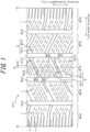
- Figure 1 is a schematic developed view of the tread pattern of the tire 1 (1A) according to the first embodiment of this disclosure.
- a part of the tread surface 2 of the tire 1A is illustrated as a developed view from the outer side in the tire radial direction to a plane (as a developed view of the tread surface 2).
- the tire 1A has, on the tread surface 2, one or more (four in the illustrated example) circumferential main grooves 3 (3A, 3B, 3C, 3D) extending in the tire circumferential direction; and a plurality (five in the illustrated example) of land portions 4 (4A, 4B, 4C, 4D, 4E) which are defined by the circumferential main grooves 3 adjacent to each other in the tire width direction of the one or more circumferential main grooves 3, or by the circumferential main groove 3 (3A or 3D) and the tread edge TE.
- the circumferential main grooves 3A and 3B are located in one half of the tire widthwise position with the tire equatorial plane CL as a boundary, and the other circumferential main grooves 3C and 3D are located in the other half of the tire widthwise position with the tire equatorial plane CL as a boundary.
- one land portion 4 (4C) is arranged on the tire equatorial plane CL and two land portions 4 (4A and 4B, 4D and 4E) are arranged on each of the tire widthwise half.
- the number of circumferential main grooves 3 in the tire 1A may be any number other than four. Depending on the number of circumferential main grooves 3, the number of land portions 4 in the tire 1A may be any number other than five. Furthermore, the tire 1A may be configured without circumferential main grooves 3 on the tread surface 2. In such a case, the tire 1A may have one land portion 4 on the tread surface 2, which is defined by both tread edges TE in the tire width direction.
- the circumferential main grooves 3 all extend along the tire circumferential direction.
- the straight line X extends along the direction Y means that the straight line X extends parallel to the direction Y, or that the straight line X extends approximately parallel to the direction Y.
- the "extending direction of the straight line X is approximately parallel to the direction Y” means, for example, that the angle between the extending direction of the straight line X and the direction Y is within 5 degrees or less.
- at least one circumferential main groove 3 may extend at an angle greater than 5 degrees with respect to the tire circumferential direction.
- all of the circumferential main grooves 3 extend in a straight line along the tire circumferential direction, however at least one of the circumferential main grooves 3 may have a shape other than a straight line, such as zigzag or curved, either entirely or partially.
- the width of the circumferential main grooves 3 is not limited, as it depends on the number of circumferential main grooves 3, but may be 4 to 15 mm, for example.
- the width of the circumferential main groove 3 is measured as the opening width perpendicular to the extending direction of the groove in the reference condition, when viewed from the outer side in the tire radial direction and developed on a flat surface.
- the depth (maximum depth) of the circumferential main groove 3 is not limited, but may be 6 to 20 mm, for example.
- the width of the circumferential main groove 3 does not have to be constant over the extending direction of the circumferential main groove 3 and may differ from each other depending on the location of the tread surface 2 where the circumferential main groove 3 is provided.
- each land portion 4 is divided into a plurality of block land portions 6 by one or more width direction grooves 5 that completely cross the land portion 4 and extend in the tire width direction.
- the land portion 4C is divided into three block land portions 6A, 6B and 6C adjacent to each other in the tire circumferential direction by two width direction grooves 5A and 5B adjacent to each other in the tire circumferential direction.
- the straight line X extends in the direction Y means that the straight line X has at least a Y-direction component. That is, "the straight line X extends in the direction Y” means that the straight line X may extend along the direction Y, or the straight line X may extend at a predetermined angle with respect to the direction Y.
- the width direction groove 5 may extend in a straight line in the tire circumferential direction, or it may extend in a shape other than a straight line, such as zigzag or curved.
- the width direction groove 5 may extend along the tire width direction, or it may extend at an angle greater than 0° and less than 45° with respect to the tire width direction, as in the illustrated example.
- the width (opening width) of the width direction groove 5 is not particularly limited, as it depends on the number of width direction grooves 5, but may be 2 to 10 mm, for example.
- the width of the width direction groove 5 is measured as the opening width perpendicular to the extending direction of the groove in the reference condition, when viewed from the outer side in the tire radial direction and developed on a flat surface.
- the depth (maximum depth) of the width direction groove 5 is not limited, but may be 5 to 20 mm, for example.
- the width of the width direction groove 5 is not limited in any way as long as it is large enough to prevent the block land portions adjacent in the tire circumferential direction from coming into contact with each other when the tire is grounded in the reference condition.
- the width of the width direction groove 5 does not have to be constant over the extending direction of the width direction groove 5 and may differ from each other depending on the location of the land portion 4 where the width direction groove 5 is provided.
- the number of width direction grooves 5 across each of the land portions 4 may be any number. Depending on the number of width direction grooves 5, the number of block land portions 6 included in the land portion 4 may be any number. Furthermore, the land portion 4 may be configured not to be crossed by the width direction groove 5, i.e., the land portion 4 may be configured as a rib-shaped land portion that continues without interruption in the tire circumferential direction.
- the land portion 4 comprises a sipe unit 8 consisting of a pair of sipes 7. More specifically, a sipe unit 8 consisting of a pair of sipes 7A and 7B is arranged in the block land portion 6 included in the land portion 4.
- sipes 7A and 7B are not specifically distinguished, they will be referred to collectively as simply sipe 7.
- Each of the pair of sipes 7A and 7B that constitutes the sipe unit 8 extends such that both ends in the extending direction of the sipe 7 terminate within the land portion 4. More specifically, each of the pair of sipes 7A and 7B extends such that both ends in the extending direction of the sipe 7 terminate within the block land portion 6.
- the sipe 7 does not have an open end that opens into the circumferential main groove 3 that defines the land portion 4 or the width direction groove 5. In this way, since the sipe 7 does not have an open end and the block land portion 6 around the sipe 7 is connected, the block land portion 6 becomes difficult to collapse around the sipe 7, and the rigidity of the block land portion 6 is improved.
- Figure 2 when an external force such as frictional force is input from the road surface to the contact patch of the tread surface 2 that is in contact with the road surface, the block land portion 6 collapses into the void side of the sipe 7. This causes to the block land portion 6 around the sipe 7 the lifting U from the road surface.
- Figure 2 schematically illustrates the lifting U of the block land portion 6 around the sipe 7.
- Figure 2 illustrates a cross-sectional view in the tire circumferential direction of the tire 1A, cut along the tire circumferential direction.
- each of the pair of sipes 7A and 7B that constitutes the sipe unit 8 extends in a straight line at an angle with respect to the tire width direction in Figure 1 , i.e., in the developed view of the tread surface 2.
- FIG. 3 schematically illustrates the arrangement of the sipe unit 8 depicted in Figure 1 .
- Figure 4 is a cross-sectional view illustrating the cross section (cross section perpendicular to the extending direction of the sipe 7) by the line A-A' indicated in Figure 3 .
- each of the pair of sipes 7A and 7B that constitute the sipe unit 8 extends in a straight line such that the angle ⁇ with respect to the tire width direction satisfies 0° ⁇ ⁇ ⁇ 45°.
- the sipes 7A and 7B are inclined to the tire width direction, which allows the sipes 7A and 7B to contribute not only to the improvement of braking and driving force in the tire circumferential direction, but also to the improvement of lateral gripping performance (turning force) in the tire width direction.
- the tire widthwise component of the sipe 7 is larger than the tire circumferential component thereof, and the sipe 7 can contribute to the improvement of braking and driving force in the tire circumferential direction, which is most important for safety.
- the sipes 7A and 7B extend parallel to each other, however, the sipes 7A and 7B may extend at different angles with respect to the tire width direction.
- the length of the sipe 7 in the extending direction thereof is indicated by a.
- the length a of the sipe 7 in the extending direction thereof is, for example, between 3 and 15 mm.
- the length a of the sipe 7 in the extending direction thereof is preferably between 3 and 10 mm, and more preferably between 3 and 5 mm.
- the length a of the sipe 7 is preferably defined within the range satisfying d ⁇ h ⁇ 100 mm 2 , and more preferably d ⁇ h ⁇ 50 mm 2 .
- the depth h of the sipe 7 may be, for example, 3 mm or more.
- the depth h of the sipe 7 may be 6.7 mm, for example.
- the cross-sectional shape of the sipe 7 in a cross section perpendicular to the extending direction thereof at the tread surface 2 is described.
- the cross-sectional shape of the sipe 7 in a cross section perpendicular to the extending direction thereof is approximately rectangular, as illustrated in Figure 4A .
- the width w of the sipe 7 is 1 mm or less as described above, and may be 0.4 mm, for example.
- the cross-sectional shape of the sipe 7 in a cross section perpendicular to the extending direction thereof may be other than rectangular.
- the sipe 7 may be shaped with the groove bottom portion bulging in a cross section perpendicular to the extending direction of the sipe 7, as illustrated in Figure 4B .
- the sipe 7 may be rounded at the bottom in a cross section perpendicular to the extending direction of the sipe 7.
- the bottom portion of the sipe 7 may be R-chamfered at both ends in the width direction of the sipe 7, or the bottom portion of the sipe 7 may be semicircular.
- the width w of the sipe 7 may be 0.4 mm, for example, in the area of 50% or more of the depth of the sipe 7.
- the sipe 7B is displaced from the sipe 7A by an offset s in the tire width direction and by an offset q in the tire circumferential direction.
- the offset s in the tire width direction of the sipes 7A and 7B may be defined, for example, in the range satisfying s ⁇ 1.5 mm.
- the pair of sipes 7A and 7B that constitute the sipe unit 8 are opposed to each other in the tire circumferential direction only in part in the tire width direction.
- a line segment X and a line segment Y are opposed to each other in the direction Z means that the line segment X and the line segment Y are separated from each other in the direction Z and that each of the ends of line segment Y is located on two straight lines extended along the direction Z from each end of the line segment X.
- the sipes 7A and 7B are opposed to each other in the tire circumferential direction only in part in the tire width direction shall include the case where only the end points of sipes 7A and 7B respectively are located on a straight line extending along the tire circumferential direction.
- the sipes 7A and 7B are offset by s in the tire width direction.
- the part 7a in the tire width direction of the sipe 7A and the part 7b in the tire width direction of the sipe 7B are opposed to each other in the tire circumferential direction.
- the sipe unit 8 can provide edge effect and water removing effect in a wider range while maintaining the sipe density in the block land portion 6. This improves the on-ice gripping performance of the tire 1A.
- a plurality of sipe units 8 are spaced apart from each other and repeatedly arranged in the tire circumferential direction to form a sipe unit row 9.
- three sipe units 8 are arranged repeatedly in the tire circumferential direction to form a sipe unit row 9.
- the number of sipe units 8 that constitute one sipe unit row 9 may be any number of two or more.
- the plurality of sipe units 8 that constitute the sipe unit row 9 are arranged repeatedly at a pitch p in the tire circumferential direction.
- the plurality of sipes 7 arranged on the block land portion 6 extend parallel to each other in the developed view of the tread surface 2.
- the sipe density in the tire circumferential direction in the block land portion 6 can be made uniform by setting q preferably in the range of (p/2) ⁇ 0.8 to (p/2) ⁇ 1.2, and more preferably to p/2. This allows the tread surface 2 to contact the road surface more uniformly and to equalize the distribution of the ground pressure applied to the ground contact patch of the tread surface 2, thereby increasing the footprint area of the tire 1A.
- the plurality of sipe units 8 that constitute the sipe unit row 9 are preferably arranged so that both ends in the tire width direction of each sipe unit are aligned on a straight line extending along the tire circumferential direction, respectively.
- both ends E1 and E2 in the tire width direction of the plurality of sipe units 8 that constitute the sipe unit row 9 are aligned on a straight line extending along the tire circumferential direction, respectively. This reduces the blank area (the area enclosed by the dashed line in the figure) where no sipes 7 are provided within the area of the block land portion 6 where the sipe unit row 9 is arranged.
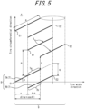
- Figure 5 illustrates an arrangement of sipe units 8, which is different from that illustrated in Figure 3 .
- both ends in the tire width direction of each of the plurality of sipe units 8 that constitute the sipe unit row 9 are not aligned on a straight line extending along the tire circumferential direction, respectively. Comparing Figures 3 and 5 , the area enclosed by the dashed line in Figure 3 is smaller than the area enclosed by the dashed line in Figure 5 . In this way, by arranging both ends in the tire width direction of the plurality of sipe units 8 that constitute the sipe unit row 9 on a straight line extending along the tire circumferential direction, the blank area where no sipes 7 are provided can be reduced within the area of the block land portion 6 where the sipe unit row 9 is arranged. However, the arrangement of the sipe units 8 may be as illustrated in Figure 5 .
- the land portion 4 comprises a plurality of sipe unit rows 9 arranged side-by-side in the tire width direction.
- two sipe unit rows 9 are arranged side by side in the tire width direction.
- four sipe unit rows 9 are arranged side by side in the tire width direction.
- the number of sipe unit rows 9 arranged in one block land portion 6 may be any number.
- FIG. 6 schematically illustrates the arrangement of a plurality of sipe unit rows 9 in the first embodiment.
- two sipe unit rows 9A and 9B are arranged side by side in the tire width direction.
- a plurality of sipes 7 in two adjacent sipe unit rows 9A and 9B in the tire width direction extend at an angle with respect to the tire width direction, in the same direction between the sipe unit rows 9A and 9B.
- the plurality of sipes 7 in the first sipe unit row 9A extend toward one side in the tire width direction (right in the figure) while being inclined toward one side in the tire circumferential direction (up in the figure).
- the plurality of sipes 7 in the second sipe unit row 9B which is adjacent to the first sipe unit row 9A extend, as well as the plurality of sipes 7 included in the first sipe unit row 9A, toward the one side in the tire width direction (right in the figure) while being inclined toward the one side in the tire circumferential direction (up in the figure).
- the plurality of sipes 7 included in the plurality of sipe unit rows 9 adjacent to each other in the tire width direction are arranged to extend in the same direction between the sipe unit rows 9, which makes it easier to arrange the blades for forming the sipes 7 in the mold during tire manufacturing and facilitates the fabrication of molds for the tire 1A.
- the tire widthwise spacing between the adjacent sipe unit rows 9A and 9B in the tire width direction is indicated by v.
- the offset in the tire circumferential direction of the adjacent sipe unit rows 9A and 9B in the tire width direction is indicated by u.
- the tire widthwise spacing v and the offset in the tire circumferential direction u may each be set to any value.
- the tire widthwise spacing v is preferably -s to s (s > 0).
- the s is the offset in the tire width direction between the pair of sipes 7 that constitute the sipe unit 8.
- the positive value of the tire widthwise spacing v means that the area between the two ends in the tire width direction of the sipe unit row 9A and the area between the two ends in the tire width direction of the sipe unit row 9B adjacent to the sipe unit row 9A in the tire width direction are spaced apart in the tire width direction by the spacing v in the tire width direction.
- the negative value of the tire widthwise spacing v means that the area between the two ends in the tire width direction of the sipe unit row 9A and the area between the two ends in the tire width direction of the sipe unit row 9B adjacent to the sipe unit row 9A in the tire width direction overlap in the tire width direction by the absolute value of the spacing v.
- the tire widthwise spacing v is set to 0 and the offset in the tire circumferential direction u is (d + s) ⁇ tan ⁇ .
- ⁇ is the angle between each of the pair of sipes 7 that constitute the sipe unit 8 and the tire width direction
- d is the length of the sipe 7 in the tire width direction
- s is the offset in the tire width direction between the pair of sipes 7 that constitute the sipe unit 8.
- the tire widthwise components of the plurality of sipes 7 are continuously arranged without gaps in the tire width direction, when the plurality of sipes 7 aligned in the tire width direction are projected along the tire circumferential direction, as illustrated by the shaded shading in Figure 7 .
- This allows the sipes 7 to be distributed evenly without gaps across the multiple sipe unit rows 9, thereby improving the edge effect and water removal effect in the block land portion 6.
- the sipe density in the block land portion 6 can be made uniform by distributing the sipes 7 evenly without gaps across the multiple sipe unit rows 9. This allows the tread surface 2 to contact the road surface more uniformly and the distribution of the ground pressure applied to the contact patch of the tread surface 2 to be equalized, thereby increasing the footprint area of the tire 1A.
- each of the plurality of sipes 7 in the second sipe unit row 9B extends over an extension line of any of the sipes 7 in the first sipe unit row 9A.
- the plurality of sipes 7 are arranged in a straight line in the tire width direction.
- sipes 7 are arranged in each of the block land portions 6 of the land portions 4A and 4E respectively, and twenty-four sipes 7 are arranged in each of the block land portions 6 of the land portions 4B, 4C, and 4D respectively.
- the number of sipes 7 arranged in one block land portion 6 may be any number.
- the number of sipes 7 arranged in the block land portion 6 may be determined based on the sipe density in the tire circumferential direction SD.
- the sipe density in the tire circumferential direction SD is a measure of the density in the tire circumferential direction of transverse sipes that completely cross the block land portion 6. If the equivalent length in the tire circumferential direction of the block land portion 6 which is obtained by dividing the outer contour area of the block land portion 6 (mm 2 ) by the maximum width BW is BL (mm), and the number of transverse sipes which are provided to completely cross the block land portion 6 is N', the average sipe spacing in the tire circumferential direction is expressed as BL/(N' + 1).
- the "outer contour area" of the block land portion 6 is the area enclosed by the outer contour of the block land portion 6 in the expanded view of the tread surface 2. Therefore, even if non-grounded areas such as sipes, small holes, narrow grooves, etc. are arranged within the block land portion 6, the area that does not exclude the area of the sipes, small holes, narrow grooves, etc. are considered.
- the following is a description of the method used to calculate the sipe density SD in this embodiment.
- a diamond-shaped block land portion 6 provided with multiple sipes 7, as illustrated in the table providing sipe shapes in Figure 14 .
- the number of equivalent sipes N is expressed as d ⁇ n/BW.
- the number of equivalent sipes N is the number of sipes when the sipes 7 in this embodiment are converted to transverse sipes (equivalent sipes) that are provided to completely cross the block land portion 6.
- the average sipe spacing in the tire circumferential direction is expressed as BL/(N + 1).
- the average sipe spacing in the tire circumferential direction is the spacing in the tire circumferential direction of the equivalent sipes in the block land portion 6, when the sipes 7 in this embodiment are converted to the equivalent sipes.
- the number n of sipes 7 in the block land portion 6, the length d in the tire width direction of the sipes 7, the maximum width BW of the block land portion 6 in the tire width direction, and the outer contour area of the block land portion 6 are the values measured in the developed view of the tread surface 2.
- a plurality of sipes 7 may be arranged in the block land portion 6 so that the sipe density SD is 0.15 (1/mm) or more. This improves the on-ice gripping performance of the tire 1A.
- a plurality of sipes 7 may be connected in the block land portion 6 by a shallow groove 10.
- Figure 8 schematically illustrates the arrangement of sipe units 8 in which the sipes 7 in the first embodiment are connected by the shallow grooves 10.
- the block land portion 6 illustrated in Figure 8 corresponds, for example, to the block land portion 6B of the tire 1A illustrated in Figure 1 .
- four of sipe unit rows 9, aligned in the tire width direction are arranged in the block land portion 6.
- three sipe units 8 are arranged repeatedly in the tire circumferential direction.
- the sipes 7, which are aligned in the tire width direction are connected by the shallow groove 10 that completely crosses the block land portion 6.
- the depth (maximum depth) H of the shallow groove 10 may be defined according to the depth h of the sipe 7.
- the depth H of the shallow groove 10 may be defined in the range of 5 to 60%, and preferably 5 to 20%, of the depth h of the sipe 7.
- the depth h of the sipe 7 may be 6.7 mm and the depth H of the shallow groove 10 may be 0.7 mm.
- the block land portion 6 of the tire 1A may be provided with sipes other than the sipe unit 8 described above.
- the land portions 4A and 4E are provided with a plurality of zigzag-shaped sipes 11 extending in the tire width direction toward the tread edge TE. This improves drainage performance at the tread surface 2, and thus the on-ice gripping performance of the tire 1A.
- FIG. 10 is a schematic developed view of the tread pattern of the tire 1B according to the second embodiment of this disclosure.
- tires 1A and 1B will be referred to collectively as simply tire 1 when no particular distinction is made between them.
- the second embodiment differs from the first embodiment in that the plurality of sipes 7 in the two adjacent sipe unit rows 9 in the tire width direction are arranged to extend in different directions between the sipe unit rows 9.
- the following is a description of the second embodiment, focusing on the points where it differs from the first embodiment. Note, that parts having the same configuration as those in the first embodiment are given the same reference numerals.
- the tire 1B has, on the tread surface 2, one or more (four in the illustrated example) circumferential main grooves 3 (3A, 3B, 3C, 3D) extending in the tire circumferential direction; and a plurality (five in the illustrated example) of land portions 4 (4A, 4B, 4C, 4D, 4E) which are defined by the circumferential main grooves 3 adjacent to each other in the tire width direction of the one or more circumferential main grooves 3, or by the circumferential main groove 3 (3A or 3D) and the tread edge TE.
- each land portion 4 is divided into a plurality of block land portions 6 by one or more width direction grooves 5 that completely cross the land portion 4 and extend in the tire width direction.
- the land portion 4C is divided into three block land portions 6A, 6B and 6C adjacent to each other in the tire circumferential direction by two width direction grooves 5A and 5B adjacent to each other in the tire circumferential direction.
- the land portion 4 comprises a sipe unit 8 consisting of a pair of sipes 7, as in the first embodiment. More specifically, a sipe unit 8, consisting of a pair of sipes 7A and 7B, is arranged in the block land portion 6 included in the land portion 4.
- each of the pair of sipes 7A and 7B that constitutes the sipe unit 8 extends such that both ends in the extending direction of the sipe 7 terminate within the land portion 4. More specifically, each of the pair of sipes 7A and 7B extends such that both ends in the extending direction of the sipe 7 terminate within the block land portion 6.
- each of the pair of sipes 7A and 7B that constitutes the sipe unit 8 extends in a straight line at an angle with respect to the tire width direction in the developed view of the tread surface 2.
- Each of the pair of sipes 7A and 7B that constitute the sipe unit 8 extends in a straight line such that the angle ⁇ with respect to the tire width direction satisfies 0° ⁇ ⁇ ⁇ 45°.
- the pair of sipes 7A and 7B that constitute the sipe unit 8 are opposed to each other in the tire circumferential direction only in part in the tire width direction.
- a plurality of sipe units 8 are repeatedly arranged in the tire circumferential direction to form a sipe unit row 9.
- three sipe units 8 are arranged repeatedly in the tire circumferential direction to form a sipe unit row 9.
- the plurality of sipe units 8 that constitute the sipe unit row 9 are preferably arranged so that both ends in the tire width direction of each sipe unit are aligned on a straight line extending along the tire circumferential direction, respectively.
- a plurality of sipe unit rows 9 are arranged side by side in the tire width direction.
- two sipe unit rows 9 are arranged side by side in the tire width direction in the block land portions 6 of the land portions 4A and 4E, respectively.
- four sipe unit rows 9 are arranged side by side in the tire width direction in the block land portions 6 of the land portions 4B, 4C and 4D, respectively.
- Figure 11 schematically illustrates the arrangement of the plurality of sipe unit rows in the second embodiment.
- two sipe unit rows 9A and 9B are arranged side by side in the tire width direction.
- a plurality of sipes 7 in two adjacent sipe unit rows 9A and 9B in the tire width direction extend at an angle with respect to the tire width direction, in a different direction between the sipe unit rows 9A and 9B.
- the plurality of sipes 7 in the first sipe unit row 9A extend toward one side in the tire width direction (right in the figure) while being inclined toward one side in the tire circumferential direction (up in the figure).
- the plurality of sipes 7 in the second sipe unit row 9B which is adjacent to the first sipe unit row 9A extend toward the one side in the tire width direction (right in the figure) while being inclined toward the other side in the tire circumferential direction (down in the figure).
- This arrangement of the sipe unit rows 9 prevents the block land portion 6 from collapsing when external force is input to the tire 1B, because the block land portion 6 is supported within the area where the adjacent sipe unit rows 9A and 9B are arranged.
- the block land portion 6 around the sipes 7 in the sipe unit row 9A collapses toward the lower right in the drawing.
- the block land portion 6 around the sipes 7 in the sipe unit row 9B collapses toward the lower left in the drawing.
- the block land portion leans and collapses in different directions within the area where the adjacent sipe unit rows 9A and 9B in the tire width direction are arranged, so that the block land portion be supported within that area, and this makes the block land portion less likely to collapse.
- This increases the rigidity of the block land portion 6.
- the tire widthwise components of the external force applied to around the sipe unit rows 9A and 9B in the block land portion 6 cancel each other out, thereby preventing unexpected forces in the tire width direction from being applied to the tire 1B and reducing the impact on the steering stability of a vehicle equipped with the tire 1B.
- the length of sipe 7 in the extending direction thereof is indicated by a, and the angle between the sipe 7 and the tire width direction is indicated by ⁇ .
- the plurality of sipes 7 in one sipe unit row 9 extend parallel to each other in the developed view of the tread surface 2.
- a pair of sipes 7A and 7B is displaced each other by an offset s in the tire width direction and by an offset q in the tire circumferential direction.
- the plurality of sipe units 8 that constitute the sipe unit row 9 are arranged repeatedly at a pitch p in the tire circumferential direction.
- the sipe density in the tire circumferential direction in the block land portion 6 can be made uniform by setting q preferably in the range of (p/2) ⁇ 0.8 to (p/2) ⁇ 1.2, and more preferably to p/2. This allows the tread surface 2 to contact the road surface more uniformly and to equalize the distribution of the ground pressure applied to the ground contact patch of the tread surface 2, thereby increasing the footprint area of the tire 1B.
- the tire widthwise spacing between the adjacent sipe unit rows 9A and 9B in the tire width direction is indicated by v.
- the offset in the tire circumferential direction of the adjacent sipe unit rows 9A and 9B in the tire width direction is indicated by u.
- the tire widthwise spacing v is preferably -s to s (s > 0).
- the s is the offset in the tire width direction between the pair of sipes 7 of the sipe unit 8 that constitute the sipe unit row 9.
- the positive value of the tire widthwise spacing v means that the area between the two ends in the tire width direction of the sipe unit row 9A and the area between the two ends in the tire width direction of the sipe unit row 9B adjacent to the sipe unit row 9A in the tire width direction are spaced apart in the tire width direction by the spacing v in the tire width direction.
- the negative value of the tire widthwise spacing v means that the area between the two ends in the tire width direction of the sipe unit row 9A and the area between the two ends in the tire width direction of the sipe unit row 9B adjacent to the sipe unit row 9A in the tire width direction overlap in the tire width direction by the absolute value of the spacing v.
- the tire widthwise spacing v is set to 0 and the offset in the tire circumferential direction u is (d + s) ⁇ tan ⁇ .
- ⁇ is the angle between each of the pair of sipes 7 that constitute the sipe unit 8 and the tire width direction
- d is the length of the sipe 7 in the tire width direction
- s is the offset in the tire width direction between the pair of sipes 7 that constitute the sipe unit 8.
- the arrangement of the sipe unit rows 9 when the tire widthwise spacing v is 0 and the offset in the tire circumferential direction u is (d + s) ⁇ tan ⁇ is schematically illustrated in Figure 12 .
- the tire widthwise components of the plurality of sipes 7 are continuously arranged without gaps in the tire width direction, when the plurality of sipes 7 aligned in the tire width direction are projected along the tire circumferential direction, as illustrated by the shaded shading in Figure 12 .
- This allows the sipes 7 to be distributed evenly without gaps across the multiple sipe unit rows 9, thereby improving the edge effect and water removal effect in the block land portion 6.
- the sipe density in the block land portion 6 can be made uniform by distributing the sipes 7 evenly without gaps across the multiple sipe unit rows 9. This allows the tread surface 2 to contact the road surface more uniformly and the distribution of the ground pressure applied to the contact patch of the tread surface 2 to be equalized, thereby increasing the footprint area of the tire 1B.
- each of the plurality of sipes 7 included in the second sipe unit row 9B extends to intersect with an extension line of any of the sipes 7 included in the first sipe unit row 9A. Therefore, when water captured in the void of one sipe 7 is drained from the sipe 7 along the extending direction of the sipe 7, the water is captured again in another sipe 7 extending to intersect with the extension line of the sipe 7, so that the on-ice gripping performance on the land portion 4 is less likely to be degraded.
- the number of sipes 7 arranged in the block land portion 6 may also be determined based on the sipe density SD, as described above in the first embodiment.
- a plurality of sipes 7 may be arranged in the block land portion 6 so that the sipe density SD is 0.15 (1/mm) or more. This prevents the reduction in rigidity of the block land portion 6 of the tire 1B due to the arrangement of the sipes 7 on the block land portion 6, which in turn prevents the reduction in the footprint area of the tire 1B. This improves the on-ice gripping performance of the tire 1B.
- a plurality of sipes 7 may also be connected in the block land portion 6 by a shallow groove 10 that crosses the block land portion 6 in the tire width direction.
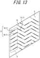
- Figure 13 schematically illustrates the arrangement of sipe units 8 in which the sipes 7 in the second embodiment are connected by the shallow grooves 10.
- the block land portion 6 illustrated in Figure 13 corresponds, for example, to the block land portion 6B of the tire 1B illustrated in Figure 10 .
- four rows of sipe unit rows 9 are arranged in the block land portion 6, aligned in the tire width direction.
- three sipe units 8 are arranged repeatedly in the tire circumferential direction.
- Each of the sipes 7 (e.g., 7Ain Figure 13 ) is connected to a sipe 7 (7C in Figure 13 ), one end of which is in an extension line along the extending direction of the sipe 7 (7A), by a shallow groove 10 that completely across the block land portion 6.
- a plurality of sipes 7 in the block land portion 6 are connected by the zigzag shallow grooves 10 that cross the block land portion 6 in the width direction groove.
- the depth H of the shallow groove 10 may be determined according to the depth h of the sipe 7, as in the first embodiment.
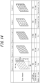
- Figure 14 is a table providing Examples and Comparative Examples.
- Figure 15 explains the block rigidity and footprint area in the Examples and Comparative Examples provided in Figure 14 .
- Finite Element Method (FEM) simulations were performed on the tires of Examples 1 to 2 and Comparative Examples 1 to 3 provided in Figure 14 under the condition of applying a vertical load, which is obtained by multiplying the outer contour area of the block land portion by a standard ground pressure for passenger vehicle tires of 230 kPa, and thereby evaluating the block rigidity and the footprint area.
- the evaluation was performed as if the sipes provided in the sipe shapes in Figure 14 were arranged in a diamond-shaped block land portion with a length in the tire circumferential direction of 45.6 mm and a length in the tire width direction of 27 mm, respectively.
- both of the block rigidity Kx (N/mm) and the actual footprint area in shear Ar (mm 2 ) were improved in Examples compared to Comparative Examples with the same sipe density.
- Comparative Example 2 had an 11% increase in Kx and a 23% increase in Kx compared to Example 2.
- the block rigidity Kx (N/mm) is the shear input value in the tire circumferential direction when the transverse displacement in the same direction is 1 mm
- the actual footprint area in shear Ar (mm 2 ) is the remaining footprint area with partial lifting when the shear input in the tire circumferential direction is 0.3 times the above vertical load.
- the on-ice gripping performance can be improved by balancing sipe density and land rigidity (in other words, by improving land rigidity while maintaining sipe density, or by increasing sipe density while maintaining land stiffness).
- the tire 1 according to an embodiment of the present disclosure improves the on-ice gripping performance of the tire 1.
- the tire 1 of each embodiment of this disclosure is a tire having a land portion 4 (block land portion 6) on a tread surface 2, wherein the land portion 4 (block land portion 6) comprises a sipe unit 8 consisting of a pair of sipes 7, each of the pair of sipes 7 extends such that both ends in the extending direction of the sipes 7 terminate within the land portion 4 (block land portion 6), and the pair of sipes 7 are opposed to each other in the tire circumferential direction only in part in the tire width direction.
- the reduction in rigidity of the land portion 4 (block land portion 6) of the tire 1 due to the arrangement of the sipes 7 on the land portion 4 (block land portion 6) can be controlled, and thus the reduction in the footprint area of the tire 1 can be controlled.
- the sipe density in the land portion 4 (block land portion 6) can be maintained while increasing the range in which the sipes 7 can exhibit edge effects and water removal effects. This improves the on-ice gripping performance of the tire 1.
- each of the pair of sipes 7 extends in a straight line such that the angle ⁇ with respect to the tire width direction satisfies 0° ⁇ ⁇ ⁇ 45°.
- the sipes 7 can contribute not only to the improvement of braking and driving force in the tire circumferential direction, but also to the improvement of lateral grip performance (turning force) in the tire width direction.
- a plurality of the sipe units 8 are repeatedly arranged in the tire circumferential direction to form a sipe unit row 9 in the land portion 4 (block land portion 6), and the plurality of the sipe units 8 that constitute the sipe unit row 9 are arranged so that both ends in the tire width direction of each sipe unit are aligned on a straight line extending along the tire circumferential direction, respectively.
- the blank areas where the sipes 7 are not provided can be reduced.
- the land portion 4 (block land portion 6) comprises a plurality of the sipe unit rows 9 arranged side-by-side in the tire width direction, among the plurality of the sipe unit rows 9, the plurality of sipes 7 in the first sipe unit row 9A extend toward one side in the tire width direction while being inclined toward one side in the tire circumferential direction, and the plurality of sipes 7 in the second sipe unit row 9B which is adjacent to the first sipe unit row 9A extend toward the one side in the tire width direction while being inclined toward the one side in the tire circumferential direction.
- Such a configuration facilitates the arrangement of the blades for forming the sipes 7 in the mold during tire manufacturing, and facilitates the fabrication of molds for the tire 1A.
- each of the plurality of sipes 7 in the second sipe unit row 9B extends over an extension line of any of the sipes 7 in the first sipe unit row 9A. According to this configuration, water captured in the voids of the sipes 7 is drained along the plurality of sipes 7, which are arranged in a straight line, toward the tire width direction, thereby further improving the on-ice gripping performance of the tire 1A.
- the land portion 4 (block land portion 6) comprises a plurality of the sipe unit rows 9 arranged side-by-side in the tire width direction, among the plurality of the sipe unit rows, the plurality of sipes 7 in the first sipe unit row 9A extend toward one side in the tire width direction while being inclined toward one side in the tire circumferential direction, and the plurality of sipes 7 in the second sipe unit row 9B which is adjacent to the first sipe unit row 9A extend toward the one side in the tire width direction while being inclined toward the other side in the tire circumferential direction.
- the block land portion 6 is prevented from collapsing when external force is input to the tire 1B, because the land portion 4 (block land portion 6) is supported in the range where the adjacent sipe unit rows 9 are arranged. This increases the rigidity of the land portion 4 (block land portion 6), which in turn increases the footprint area of the tire 1B. This further improves the on-ice gripping performance of the tire 1B.
- the length of the sipe 7 in the tire width direction is d (mm) and the depth of the sipe 7 is h (mm)
- d ⁇ h 150 (mm 2 ) or less
- the number of the sipes 7 in the land portion 4 (block land portion 6) is n
- the maximum width of the land portion 4 (block land portion 6) in the tire width direction is BW (mm)
- the equivalent length in the tire circumferential direction of the land portion 4 (block land portion 6) which is obtained by dividing the outer contour area of the land portion 4 (block land portion 6) (mm 2 ) by the maximum width BW is BL (mm)
- the number of equivalent sipes N is expressed as d ⁇ n/BW
- the average sipe spacing in the tire circumferential direction is expressed as BL/(N + 1)
- the sipe density can be increased while controlling the reduction in rigidity of the land portion 4 (block land portion 6) of the tire 1 due to the arrangement of the sipes 7 on the land portion 4 (block land portion 6). This improves the on-ice gripping performance of the tire 1.
Landscapes
- Engineering & Computer Science (AREA)
- Mechanical Engineering (AREA)
- Tires In General (AREA)
Abstract
Description
- This disclosure relates to a tire.
- Conventionally, narrow grooves called sipes have been provided in the land portion of the tread of tires, particularly studless tires, in order to improve on-ice gripping performance of the tire. These sipes allow water that gushes out when the icy road surface melts on the contact patch of the tire to be discharged to the outside of the contact patch, thereby improving the on-ice gripping performance of the tire.
- For example,
Patent Document 1 proposes a technique that improves the on-ice gripping performance by densely arranging sipes while preventing a reduction in rigidity of the land portion. - PTL 1:
JP 2005-186827 A1 - However, the compatibility between the rigidity of the land portion and the water drainage by the sipes in the prior art is not sufficient, and further improvement on the on-ice gripping performance of the tire is still required.
- It is an object of the present disclosure, made in view of the above circumstances, to provide a tire with improved on-ice gripping performance.
- The tire according to the present disclosure is a tire having a land portion on a tread surface, wherein the land portion comprises a sipe unit consisting of a pair of sipes, each of the pair of sipes extends such that both ends in the extending direction of sipes terminate within the land portion, and the pair of sipes are opposed to each other in the tire circumferential direction only in part in the tire width direction.
- According to the present disclosure, it is possible to provide a tire with improved on-ice gripping performance.
- In the accompanying drawings:
-
FIG. 1 is a schematic developed view of the tread pattern of the tire according to the first embodiment of this disclosure; -
FIG. 2 schematically illustrates the lifting of the block land portion around a sipe; -
FIG. 3 schematically illustrates the arrangement of sipe units depicted inFIG. 1 ; -
FIG. 4A is a cross-sectional view illustrating the cross section according to the line A-A' indicated inFIG. 3 ; -
FIG. 4B is a cross-sectional view illustrating the cross section according to the line A-A' indicated inFIG. 3 ; -
FIG. 5 schematically illustrates a different arrangement of sipe units than inFIG. 3 ; -
FIG. 6 schematically illustrates the arrangement of a plurality of sipe unit rows in the first embodiment; -
FIG. 7 schematically illustrates the arrangement of sipe unit rows when the tire widthwise spacing v is 0 and the tire circumferential offset u is (d + s) × tan ϕ; -
FIG. 8 schematically illustrates the arrangement of sipe units in which the sipes in the first embodiment are connected by shallow grooves; -
FIG. 9 is a cross-sectional view illustrating the cross section according to the line B-B' indicated inFIG. 8 ; -
FIG. 10 is a schematic developed view of the tread pattern of the tire according to the second embodiment of this disclosure; -
FIG. 11 schematically illustrates the arrangement of a plurality of sipe unit rows in the second embodiment; -
FIG. 12 schematically illustrates the arrangement of sipe unit rows when the tire widthwise spacing v is 0 and the tire circumferential offset u is (d + s) × tan ϕ; -
FIG. 13 schematically illustrates the arrangement of sipe units in which the sipes in the second embodiment are connected by shallow grooves; -
FIG. 14 a table providing Examples and Comparative Examples; and -
FIG. 15 explains the block rigidity and the footprint area in the Examples and Comparative Examples provided inFIG. 14 . - Hereinafter, embodiments of a tire according to the present disclosure will be described with reference to the drawings. Common members and parts in each figure are designated by the same reference numerals. However, it should be noted that the drawings are schematically drawn, and the ratio of each dimension may differ from the actual one.
- As used herein, the "tire width direction" refers to the direction parallel to the tire rotation axis, and the "tire radial direction" refers to the direction perpendicular to the tire rotation axis. The "tire circumferential direction" refers to the direction in which the tire rotates around the tire rotation axis.
- As used herein, the side closer to the tire rotation axis along the tire radial direction is referred to as the "inner side in the tire radial direction" and the side farther from the tire rotation axis along the tire radial direction is referred to as the "outer side in the tire radial direction". At the same time, the side closer to the tire equatorial plane CL along the tire width direction is referred to as the "inner side in the tire width direction" and the side farther from the tire equatorial plane CL along the tire width direction is referred to as the "outer side in the tire width direction".
- As used herein, unless otherwise noted, the positional relationship of each element of the tire, etc., shall be measured in a reference condition. In this document, the "reference condition" refers to the condition in which the tire is mounted on a rim of a wheel, which is an applicable rim, filled with prescribed internal pressure, and unloaded.
- As used herein, the "applicable rim" refers to the standard rim in the applicable size (Measuring Rim in ETRTO's STANDARDS MANUAL and Design Rim in TRA's YEAR BOOK) as described or as may be described in the future in the industrial standard, which is valid for the region in which the tire is produced and used, such as JATMA YEAR BOOK of JATMA (Japan Automobile Tyre Manufacturers Association) in Japan, STANDARDS MANUAL of ETRTO (The European Tyre and Rim Technical Organization) in Europe, and YEAR BOOK of TRA (The Tire and Rim Association, Inc.) in the United States. For sizes not listed in these industrial standards, the "applicable rim" refers to a rim with a width corresponding to the bead width of the tire. The "applicable rim" includes current sizes as well as future sizes to be listed in the aforementioned industrial standards. An example of the "size as described in the future" could be the sizes listed as "FUTURE DEVELOPMENTS" in the ETRTO 2013 edition.
- As used herein, the "prescribed internal pressure" refers to the air pressure (maximum air pressure) corresponding to the maximum load capacity of a single wheel in the applicable size and ply rating, as described in the aforementioned JATMA YEAR BOOK and other industrial standards. In the case that the size is not listed in the aforementioned industrial standards, the "prescribed internal pressure" refers to the air pressure (maximum air pressure) corresponding to the maximum load capacity specified for each vehicle in which the tire is mounted. In addition, as used herein, the "prescribed load" refers to the load corresponding to the maximum load capacity of a single tire in the applicable size and ply rating described in the aforementioned industrial standards, or, for sizes not listed in the aforementioned industrial standards, the "prescribed load" refers to the load corresponding to the maximum load capacity specified for each vehicle in which the tire is mounted.
- As used herein, the "tread surface" means the outer surface around the entire circumference of the tire that is in contact with the road surface when the tire is assembled on the applicable rim, filled with the prescribed internal pressure, and rolled under the prescribed load (hereinafter also referred to as the "maximum load condition"). In addition, the "tread edge" means the outer edge of the tread surface in the tire width direction.
- As used herein, the "sipe" is defined as a sipe with a width of 1 mm or less in the area of 50% or more of the depth of the sipe in the above reference condition. Here, the "depth of sipe" shall be measured perpendicular to the tread surface in the above reference condition, and the "width of sipe" shall be measured in a cross section perpendicular to the extending direction of the sipes at the tread surface, parallel to the tread surface, in the above reference condition. In addition, the "length in the extending direction of the sipe" refers to the length of the centerline consisting of a series of sipe widthwise center points on the tread surface in the reference condition. The distance and length, etc. associated with the sipe shall also be measured, with respect to the above centerline, in the developed view of the tread surface, unless otherwise noted.
- In this embodiment, unless otherwise noted, the internal structure, etc. of the tire can be the same as that of a conventional tire. As an example, the tire may have a pair of bead portions, a pair of sidewall portions connected to the pair of bead portions, and a tread portion disposed between the pair of sidewall portions. Also, the tire may have a carcass that straddles toroidally between the pair of bead portions, and a belt disposed on the outer side of the crown portion of the carcass in the tire radial direction.
- In the following, the tire is described as one whose lumen is filled with air and mounted on a vehicle such as a passenger car. However, the tire lumen may be filled with a fluid other than air, and the tire may be mounted on a vehicle other than a passenger car.
- Hereinafter, a
tire 1 according to an embodiment of the present disclosure will be described with reference to the drawings. -
Figure 1 is a schematic developed view of the tread pattern of the tire 1 (1A) according to the first embodiment of this disclosure. InFigure 1 , a part of thetread surface 2 of thetire 1A is illustrated as a developed view from the outer side in the tire radial direction to a plane (as a developed view of the tread surface 2). - As illustrated in
Figure 1 , thetire 1A has, on thetread surface 2, one or more (four in the illustrated example) circumferential main grooves 3 (3A, 3B, 3C, 3D) extending in the tire circumferential direction; and a plurality (five in the illustrated example) of land portions 4 (4A, 4B, 4C, 4D, 4E) which are defined by the circumferentialmain grooves 3 adjacent to each other in the tire width direction of the one or more circumferentialmain grooves 3, or by the circumferential main groove 3 (3A or 3D) and the tread edge TE. In this embodiment, the circumferentialmain grooves 3A and 3B are located in one half of the tire widthwise position with the tire equatorial plane CL as a boundary, and the other circumferentialmain grooves - The number of circumferential
main grooves 3 in thetire 1A may be any number other than four. Depending on the number of circumferentialmain grooves 3, the number ofland portions 4 in thetire 1A may be any number other than five. Furthermore, thetire 1A may be configured without circumferentialmain grooves 3 on thetread surface 2. In such a case, thetire 1A may have oneland portion 4 on thetread surface 2, which is defined by both tread edges TE in the tire width direction. - In the illustrated example, the circumferential
main grooves 3 all extend along the tire circumferential direction. As used herein, "the straight line X extends along the direction Y" means that the straight line X extends parallel to the direction Y, or that the straight line X extends approximately parallel to the direction Y. The "extending direction of the straight line X is approximately parallel to the direction Y" means, for example, that the angle between the extending direction of the straight line X and the direction Y is within 5 degrees or less. However, at least one circumferentialmain groove 3 may extend at an angle greater than 5 degrees with respect to the tire circumferential direction. In the illustrated example, all of the circumferentialmain grooves 3 extend in a straight line along the tire circumferential direction, however at least one of the circumferentialmain grooves 3 may have a shape other than a straight line, such as zigzag or curved, either entirely or partially. - The width of the circumferential
main grooves 3 is not limited, as it depends on the number of circumferentialmain grooves 3, but may be 4 to 15 mm, for example. The width of the circumferentialmain groove 3 is measured as the opening width perpendicular to the extending direction of the groove in the reference condition, when viewed from the outer side in the tire radial direction and developed on a flat surface. Similarly, the depth (maximum depth) of the circumferentialmain groove 3 is not limited, but may be 6 to 20 mm, for example. The width of the circumferentialmain groove 3 does not have to be constant over the extending direction of the circumferentialmain groove 3 and may differ from each other depending on the location of thetread surface 2 where the circumferentialmain groove 3 is provided. - In the
tire 1A, eachland portion 4 is divided into a plurality ofblock land portions 6 by one or morewidth direction grooves 5 that completely cross theland portion 4 and extend in the tire width direction. - In the illustrated example, all of the
width direction grooves 5 completely cross theland portion 4 and extend in the tire width direction. For example, within the illustration, theland portion 4C is divided into threeblock land portions width direction grooves width direction groove 5 may extend in a straight line in the tire circumferential direction, or it may extend in a shape other than a straight line, such as zigzag or curved. Thewidth direction groove 5 may extend along the tire width direction, or it may extend at an angle greater than 0° and less than 45° with respect to the tire width direction, as in the illustrated example. - The width (opening width) of the
width direction groove 5 is not particularly limited, as it depends on the number ofwidth direction grooves 5, but may be 2 to 10 mm, for example. The width of thewidth direction groove 5 is measured as the opening width perpendicular to the extending direction of the groove in the reference condition, when viewed from the outer side in the tire radial direction and developed on a flat surface. Similarly, the depth (maximum depth) of thewidth direction groove 5 is not limited, but may be 5 to 20 mm, for example. However, the width of thewidth direction groove 5 is not limited in any way as long as it is large enough to prevent the block land portions adjacent in the tire circumferential direction from coming into contact with each other when the tire is grounded in the reference condition. In addition, the width of thewidth direction groove 5 does not have to be constant over the extending direction of thewidth direction groove 5 and may differ from each other depending on the location of theland portion 4 where thewidth direction groove 5 is provided. - The number of
width direction grooves 5 across each of theland portions 4 may be any number. Depending on the number ofwidth direction grooves 5, the number ofblock land portions 6 included in theland portion 4 may be any number. Furthermore, theland portion 4 may be configured not to be crossed by thewidth direction groove 5, i.e., theland portion 4 may be configured as a rib-shaped land portion that continues without interruption in the tire circumferential direction. - The
land portion 4 comprises asipe unit 8 consisting of a pair ofsipes 7. More specifically, asipe unit 8 consisting of a pair ofsipes block land portion 6 included in theland portion 4. Hereafter, when thesipes sipe 7. - Each of the pair of
sipes sipe unit 8 extends such that both ends in the extending direction of thesipe 7 terminate within theland portion 4. More specifically, each of the pair ofsipes sipe 7 terminate within theblock land portion 6. In other words, thesipe 7 does not have an open end that opens into the circumferentialmain groove 3 that defines theland portion 4 or thewidth direction groove 5. In this way, since thesipe 7 does not have an open end and theblock land portion 6 around thesipe 7 is connected, theblock land portion 6 becomes difficult to collapse around thesipe 7, and the rigidity of theblock land portion 6 is improved. - Generally, as illustrated in
Figure 2 , when an external force such as frictional force is input from the road surface to the contact patch of thetread surface 2 that is in contact with the road surface, theblock land portion 6 collapses into the void side of thesipe 7. This causes to theblock land portion 6 around thesipe 7 the lifting U from the road surface.Figure 2 schematically illustrates the lifting U of theblock land portion 6 around thesipe 7.Figure 2 illustrates a cross-sectional view in the tire circumferential direction of thetire 1A, cut along the tire circumferential direction. When external force is applied to thetire 1A in the direction indicated by the arrow inFigure 2 , the lifting occurs in theblock land portion 6 on the side where the external force is applied, with thesipe 7 as the boundary. In contrast, when theblock land portion 6 around thesipe 7 is connected to each other, since theblock land potion 6 around thesipe 7 restrains each other and can control the lifting U of theblock land portion 6 around thesipe 7 caused by the input of external force from the road surface, thereby the footprint area of thetire 1A at the time of the input of external force can be increased. This prevents the reduction in rigidity of the land portion of thetire 1A due to the arrangement of thesipes 7 on theblock land portion 6, which in turn prevents the reduction in the footprint area of thetire 1A. Therefore, the on-ice gripping performance of thetire 1A is improved. - Referring again to
Figure 1 , each of the pair ofsipes sipe unit 8 extends in a straight line at an angle with respect to the tire width direction inFigure 1 , i.e., in the developed view of thetread surface 2. - The configuration of the
sipe unit 8 is explained below with reference toFigures 3 and4 .Figure 3 schematically illustrates the arrangement of thesipe unit 8 depicted inFigure 1 .Figure 4 is a cross-sectional view illustrating the cross section (cross section perpendicular to the extending direction of the sipe 7) by the line A-A' indicated inFigure 3 . InFigure 3 , each of the pair ofsipes sipe unit 8 extends in a straight line such that the angle ϕ with respect to the tire width direction satisfies 0° < ϕ < 45°. In this way, thesipes sipes sipe 7 is larger than the tire circumferential component thereof, and thesipe 7 can contribute to the improvement of braking and driving force in the tire circumferential direction, which is most important for safety. In this embodiment, thesipes sipes - In
Figure 3 , the length of thesipe 7 in the extending direction thereof is indicated by a. The length a of thesipe 7 in the extending direction thereof is, for example, between 3 and 15 mm. The length a of thesipe 7 in the extending direction thereof is preferably between 3 and 10 mm, and more preferably between 3 and 5 mm. The length a of thesipe 7 may be defined according to the depth (maximum depth) h of thesipe 7. Specifically, the length a of thesipe 7 may be determined according to the depth h within the range where the length d of thesipe 7 in the tire width direction (d = a × cos ϕ) and the depth h of thesipe 7 satisfy d × h ≤ 150 mm2. The length a of thesipe 7 is preferably defined within the range satisfying d × h ≤ 100 mm2, and more preferably d × h ≤ 50 mm2. The depth h of thesipe 7 may be, for example, 3 mm or more. The depth h of thesipe 7 may be 6.7 mm, for example. - Referring to
Figure 4 , the cross-sectional shape of thesipe 7 in a cross section perpendicular to the extending direction thereof at thetread surface 2 is described. In this embodiment, the cross-sectional shape of thesipe 7 in a cross section perpendicular to the extending direction thereof is approximately rectangular, as illustrated inFigure 4A . In thesipe 7 illustrated inFigure 4A , the width w of thesipe 7 is 1 mm or less as described above, and may be 0.4 mm, for example. However, the cross-sectional shape of thesipe 7 in a cross section perpendicular to the extending direction thereof may be other than rectangular. For example, thesipe 7 may be shaped with the groove bottom portion bulging in a cross section perpendicular to the extending direction of thesipe 7, as illustrated inFigure 4B . In addition, for example, thesipe 7 may be rounded at the bottom in a cross section perpendicular to the extending direction of thesipe 7. For example, in the cross section of thesipe 7 perpendicular to the extending direction thereof illustrated inFigure 4A , the bottom portion of thesipe 7 may be R-chamfered at both ends in the width direction of thesipe 7, or the bottom portion of thesipe 7 may be semicircular. In thesipe 7 illustrated inFigure 4B , the width w of thesipe 7 may be 0.4 mm, for example, in the area of 50% or more of the depth of thesipe 7. - Referring again to
Figure 3 , thesipe 7B is displaced from thesipe 7A by an offset s in the tire width direction and by an offset q in the tire circumferential direction. The offset s in the tire width direction of thesipes - The pair of
sipes sipe unit 8 are opposed to each other in the tire circumferential direction only in part in the tire width direction. Here, "a line segment X and a line segment Y are opposed to each other in the direction Z" means that the line segment X and the line segment Y are separated from each other in the direction Z and that each of the ends of line segment Y is located on two straight lines extended along the direction Z from each end of the line segment X. However, "thesipes sipes sipes Figure 3 , thepart 7a in the tire width direction of thesipe 7A and thepart 7b in the tire width direction of thesipe 7B are opposed to each other in the tire circumferential direction. Here, the length d in the tire width direction of each of thesipes sipes sipes sipe unit 8 are projected along the tire circumferential direction, at least one of thesipes sipe unit 8 in the tire width direction, as indicated by the shaded shading inFigure 3 . Therefore, by increasing the length of thesipe unit 8 included in the tire width direction within the range where d - s ≥0 is satisfied without changing the length of each of thesipes sipe unit 8, thesipe unit 8 can provide edge effect and water removing effect in a wider range while maintaining the sipe density in theblock land portion 6. This improves the on-ice gripping performance of thetire 1A. - Referring again to
Figure 1 , in theland portion 4, a plurality ofsipe units 8 are spaced apart from each other and repeatedly arranged in the tire circumferential direction to form asipe unit row 9. In the illustrated example, in oneblock land portion 6, threesipe units 8 are arranged repeatedly in the tire circumferential direction to form asipe unit row 9. However, the number ofsipe units 8 that constitute onesipe unit row 9 may be any number of two or more. - In
Figure 3 , the plurality ofsipe units 8 that constitute thesipe unit row 9 are arranged repeatedly at a pitch p in the tire circumferential direction. In this embodiment, the plurality ofsipes 7 arranged on theblock land portion 6 extend parallel to each other in the developed view of thetread surface 2. Here, when the distance in the tire circumferential direction betweenadjacent sipe units 8 in the tire circumferential direction in thesipe unit row 9 is denoted as the distance r between units, the distance r between units is indicated by r = p - q. In particular, when the pitch p of thesipe unit 8 that constitute thesipe unit row 9 and the offset q in the tire circumferential direction of the sipes that constitute thesipe unit 8 is q = p/2, r = q holds true, then all thesipes 7 in thesipe unit row 9 are equally spaced in the tire circumferential direction. Therefore, the sipe density in the tire circumferential direction in theblock land portion 6 can be made uniform by setting q preferably in the range of (p/2) × 0.8 to (p/2) × 1.2, and more preferably to p/2. This allows thetread surface 2 to contact the road surface more uniformly and to equalize the distribution of the ground pressure applied to the ground contact patch of thetread surface 2, thereby increasing the footprint area of thetire 1A. - The plurality of
sipe units 8 that constitute thesipe unit row 9 are preferably arranged so that both ends in the tire width direction of each sipe unit are aligned on a straight line extending along the tire circumferential direction, respectively. Specifically, inFigure 3 , both ends E1 and E2 in the tire width direction of the plurality ofsipe units 8 that constitute thesipe unit row 9 are aligned on a straight line extending along the tire circumferential direction, respectively. This reduces the blank area (the area enclosed by the dashed line in the figure) where nosipes 7 are provided within the area of theblock land portion 6 where thesipe unit row 9 is arranged. As a comparison,Figure 5 illustrates an arrangement ofsipe units 8, which is different from that illustrated inFigure 3 . InFigure 5 , both ends in the tire width direction of each of the plurality ofsipe units 8 that constitute thesipe unit row 9 are not aligned on a straight line extending along the tire circumferential direction, respectively. ComparingFigures 3 and5 , the area enclosed by the dashed line inFigure 3 is smaller than the area enclosed by the dashed line inFigure 5 . In this way, by arranging both ends in the tire width direction of the plurality ofsipe units 8 that constitute thesipe unit row 9 on a straight line extending along the tire circumferential direction, the blank area where nosipes 7 are provided can be reduced within the area of theblock land portion 6 where thesipe unit row 9 is arranged. However, the arrangement of thesipe units 8 may be as illustrated inFigure 5 . - Referring again to
Figure 1 , theland portion 4 comprises a plurality ofsipe unit rows 9 arranged side-by-side in the tire width direction. In the illustrated example, in each of theblock land portions 6 of theland portions sipe unit rows 9 are arranged side by side in the tire width direction. Also, in each of theblock land portions 6 of theblock land portions sipe unit rows 9 are arranged side by side in the tire width direction. However, the number ofsipe unit rows 9 arranged in oneblock land portion 6 may be any number. - The arrangement of a plurality of
sipe unit rows 9 in the first embodiment is described below with reference toFigure 6. Figure 6 schematically illustrates the arrangement of a plurality ofsipe unit rows 9 in the first embodiment. InFigure 6 , twosipe unit rows - In the first embodiment illustrated in
Figure 6 , a plurality ofsipes 7 in two adjacentsipe unit rows sipe unit rows sipe unit rows sipes 7 in the firstsipe unit row 9A extend toward one side in the tire width direction (right in the figure) while being inclined toward one side in the tire circumferential direction (up in the figure). Furthermore, the plurality ofsipes 7 in the secondsipe unit row 9B which is adjacent to the firstsipe unit row 9A extend, as well as the plurality ofsipes 7 included in the firstsipe unit row 9A, toward the one side in the tire width direction (right in the figure) while being inclined toward the one side in the tire circumferential direction (up in the figure). - Thus, the plurality of
sipes 7 included in the plurality ofsipe unit rows 9 adjacent to each other in the tire width direction are arranged to extend in the same direction between thesipe unit rows 9, which makes it easier to arrange the blades for forming thesipes 7 in the mold during tire manufacturing and facilitates the fabrication of molds for thetire 1A. - In
Figure 6 , the tire widthwise spacing between the adjacentsipe unit rows sipe unit rows - The tire widthwise spacing v is preferably -s to s (s > 0). Here, the s is the offset in the tire width direction between the pair of
sipes 7 that constitute thesipe unit 8. As illustrated inFigure 6 , the positive value of the tire widthwise spacing v means that the area between the two ends in the tire width direction of thesipe unit row 9A and the area between the two ends in the tire width direction of thesipe unit row 9B adjacent to thesipe unit row 9A in the tire width direction are spaced apart in the tire width direction by the spacing v in the tire width direction. On the other hand, the negative value of the tire widthwise spacing v means that the area between the two ends in the tire width direction of thesipe unit row 9A and the area between the two ends in the tire width direction of thesipe unit row 9B adjacent to thesipe unit row 9A in the tire width direction overlap in the tire width direction by the absolute value of the spacing v. By defining the tire widthwise spacing v in this manner, the blank area (the area enclosed by the dashed line in the figure) where nosipes 7 are provided is reduced within the area of theblock land portion 6 where the adjacentsipe unit rows - More preferably, the tire widthwise spacing v is set to 0 and the offset in the tire circumferential direction u is (d + s) × tan ϕ. Here, ϕ is the angle between each of the pair of
sipes 7 that constitute thesipe unit 8 and the tire width direction, d is the length of thesipe 7 in the tire width direction, and s is the offset in the tire width direction between the pair ofsipes 7 that constitute thesipe unit 8. The arrangement of thesipe unit rows 9, when the tire widthwise spacing v is 0 and the offset in the tire circumferential direction u is (d + s) × tan ϕ, is schematically illustrated inFigure 7 . - By setting the tire widthwise spacing v to 0, the tire widthwise components of the plurality of
sipes 7 are continuously arranged without gaps in the tire width direction, when the plurality ofsipes 7 aligned in the tire width direction are projected along the tire circumferential direction, as illustrated by the shaded shading inFigure 7 . This allows thesipes 7 to be distributed evenly without gaps across the multiplesipe unit rows 9, thereby improving the edge effect and water removal effect in theblock land portion 6. In addition, the sipe density in theblock land portion 6 can be made uniform by distributing thesipes 7 evenly without gaps across the multiplesipe unit rows 9. This allows thetread surface 2 to contact the road surface more uniformly and the distribution of the ground pressure applied to the contact patch of thetread surface 2 to be equalized, thereby increasing the footprint area of thetire 1A. - In
Figure 7 , each of the plurality ofsipes 7 in the secondsipe unit row 9B extends over an extension line of any of thesipes 7 in the firstsipe unit row 9A. As a result, in theblock land portion 6, the plurality ofsipes 7 are arranged in a straight line in the tire width direction. Because of this, by setting u preferably in the range of ((d + s) × tan ϕ) × 0.8 to ((d + s) × tan ϕ) × 1.2, and more preferably to (d + s) × tan ϕ, water captured in the voids of thesipes 7 is drained along the plurality ofsipes 7 which are arranged in a straight line, toward the tire width direction, thereby improving the on-ice gripping performance on theland portion 4. Furthermore, the plurality ofsipes 7 in the adjacentsipe unit rows sipes 7. - Referring again to
Figure 1 , twelvesipes 7 are arranged in each of theblock land portions 6 of theland portions sipes 7 are arranged in each of theblock land portions 6 of theland portions sipes 7 arranged in oneblock land portion 6 may be any number. - For example, the number of
sipes 7 arranged in theblock land portion 6 may be determined based on the sipe density in the tire circumferential direction SD. The sipe density in the tire circumferential direction SD is a measure of the density in the tire circumferential direction of transverse sipes that completely cross theblock land portion 6. If the equivalent length in the tire circumferential direction of theblock land portion 6 which is obtained by dividing the outer contour area of the block land portion 6 (mm2) by the maximum width BW is BL (mm), and the number of transverse sipes which are provided to completely cross theblock land portion 6 is N', the average sipe spacing in the tire circumferential direction is expressed as BL/(N' + 1). The sipe density SD in the tire circumferential direction is expressed as the reciprocal of the average sipe spacing by the following formula (1).
- The "outer contour area" of the
block land portion 6 is the area enclosed by the outer contour of theblock land portion 6 in the expanded view of thetread surface 2. Therefore, even if non-grounded areas such as sipes, small holes, narrow grooves, etc. are arranged within theblock land portion 6, the area that does not exclude the area of the sipes, small holes, narrow grooves, etc. are considered. - The following is a description of the method used to calculate the sipe density SD in this embodiment. For example, assume a diamond-shaped
block land portion 6 provided withmultiple sipes 7, as illustrated in the table providing sipe shapes inFigure 14 . First, if the number ofsipes 7 in theblock land portion 6 is n, the length ofsipes 7 in the tire width direction is d (mm), and the maximum width of theblock land portion 6 in the tire width direction is BW (mm), the number of equivalent sipes N is expressed as d × n/BW. Here, the number of equivalent sipes N is the number of sipes when thesipes 7 in this embodiment are converted to transverse sipes (equivalent sipes) that are provided to completely cross theblock land portion 6. Furthermore, if the equivalent length in the tire circumferential direction of theblock land portion 6 is BL (mm), the average sipe spacing in the tire circumferential direction is expressed as BL/(N + 1). Here, the average sipe spacing in the tire circumferential direction is the spacing in the tire circumferential direction of the equivalent sipes in theblock land portion 6, when thesipes 7 in this embodiment are converted to the equivalent sipes. The sipe density SD in the tire circumferential direction is expressed as the reciprocal of the average sipe spacing by the following formula (2).
- Note, that the number n of
sipes 7 in theblock land portion 6, the length d in the tire width direction of thesipes 7, the maximum width BW of theblock land portion 6 in the tire width direction, and the outer contour area of theblock land portion 6 are the values measured in the developed view of thetread surface 2. - For example, a plurality of
sipes 7 may be arranged in theblock land portion 6 so that the sipe density SD is 0.15 (1/mm) or more. This improves the on-ice gripping performance of thetire 1A. - A plurality of
sipes 7 may be connected in theblock land portion 6 by ashallow groove 10.Figure 8 schematically illustrates the arrangement ofsipe units 8 in which thesipes 7 in the first embodiment are connected by theshallow grooves 10. Theblock land portion 6 illustrated inFigure 8 corresponds, for example, to theblock land portion 6B of thetire 1A illustrated inFigure 1 . InFigure 8 , four ofsipe unit rows 9, aligned in the tire width direction, are arranged in theblock land portion 6. In each of thesipe unit rows 9, threesipe units 8 are arranged repeatedly in the tire circumferential direction. InFigure 8 , thesipes 7, which are aligned in the tire width direction, are connected by theshallow groove 10 that completely crosses theblock land portion 6. A cross-section (B-B' section) of thetire 1A that is cut along the extending direction of theshallow groove 10 illustrated inFigure 8 is illustrated inFigure 9 . InFigure 9 , the depth (maximum depth) H of theshallow groove 10 may be defined according to the depth h of thesipe 7. For example, the depth H of theshallow groove 10 may be defined in the range of 5 to 60%, and preferably 5 to 20%, of the depth h of thesipe 7. For example, the depth h of thesipe 7 may be 6.7 mm and the depth H of theshallow groove 10 may be 0.7 mm. With this configuration, water captured in the voids of thesipes 7 is drained through theshallow grooves 10 toward the tire width direction, thereby improving the on-ice gripping performance in theblock land portion 6. - Referring again to
Figure 1 , theblock land portion 6 of thetire 1A may be provided with sipes other than thesipe unit 8 described above. For example, in the illustrated example, theland portions sipes 11 extending in the tire width direction toward the tread edge TE. This improves drainage performance at thetread surface 2, and thus the on-ice gripping performance of thetire 1A. - Hereinafter, a tire 1 (1B) according to the second embodiment of the present disclosure will be described with reference to
Figure 10. Figure 10 is a schematic developed view of the tread pattern of the tire 1B according to the second embodiment of this disclosure. Hereafter,tires 1A and 1B will be referred to collectively as simply tire 1 when no particular distinction is made between them. - As illustrated in
Figure 10 , the second embodiment differs from the first embodiment in that the plurality ofsipes 7 in the two adjacentsipe unit rows 9 in the tire width direction are arranged to extend in different directions between thesipe unit rows 9. The following is a description of the second embodiment, focusing on the points where it differs from the first embodiment. Note, that parts having the same configuration as those in the first embodiment are given the same reference numerals. - As in the first embodiment, the tire 1B has, on the
tread surface 2, one or more (four in the illustrated example) circumferential main grooves 3 (3A, 3B, 3C, 3D) extending in the tire circumferential direction; and a plurality (five in the illustrated example) of land portions 4 (4A, 4B, 4C, 4D, 4E) which are defined by the circumferentialmain grooves 3 adjacent to each other in the tire width direction of the one or more circumferentialmain grooves 3, or by the circumferential main groove 3 (3A or 3D) and the tread edge TE. - As in the first embodiment, in the tire 1B, each
land portion 4 is divided into a plurality ofblock land portions 6 by one or morewidth direction grooves 5 that completely cross theland portion 4 and extend in the tire width direction. For example, within the illustration, theland portion 4C is divided into threeblock land portions width direction grooves - The
land portion 4 comprises asipe unit 8 consisting of a pair ofsipes 7, as in the first embodiment. More specifically, asipe unit 8, consisting of a pair ofsipes block land portion 6 included in theland portion 4. - As in the first embodiment, each of the pair of
sipes sipe unit 8 extends such that both ends in the extending direction of thesipe 7 terminate within theland portion 4. More specifically, each of the pair ofsipes sipe 7 terminate within theblock land portion 6. - As in the first embodiment, each of the pair of
sipes sipe unit 8 extends in a straight line at an angle with respect to the tire width direction in the developed view of thetread surface 2. Each of the pair ofsipes sipe unit 8 extends in a straight line such that the angle ϕ with respect to the tire width direction satisfies 0° < ϕ < 45°. - As in the first embodiment, the pair of
sipes sipe unit 8 are opposed to each other in the tire circumferential direction only in part in the tire width direction. - As in the first embodiment, in the
land portion 4, a plurality ofsipe units 8 are repeatedly arranged in the tire circumferential direction to form asipe unit row 9. In the illustrated example, in oneblock land portion 6, threesipe units 8 are arranged repeatedly in the tire circumferential direction to form asipe unit row 9. The plurality ofsipe units 8 that constitute thesipe unit row 9 are preferably arranged so that both ends in the tire width direction of each sipe unit are aligned on a straight line extending along the tire circumferential direction, respectively. - In the
land portion 4, a plurality ofsipe unit rows 9 are arranged side by side in the tire width direction. In the illustrated example, twosipe unit rows 9 are arranged side by side in the tire width direction in theblock land portions 6 of theland portions block land portions sipe unit rows 9 are arranged side by side in the tire width direction in theblock land portions 6 of theland portions - Hereinafter, referring to
Figure 11 , the arrangement of the plurality ofsipe unit rows 9 in the second embodiment is described.Figure 11 schematically illustrates the arrangement of the plurality of sipe unit rows in the second embodiment. InFigure 11 , twosipe unit rows - In the second embodiment illustrated in
Figure 11 , unlike the first embodiment, a plurality ofsipes 7 in two adjacentsipe unit rows sipe unit rows sipe unit rows sipes 7 in the firstsipe unit row 9A extend toward one side in the tire width direction (right in the figure) while being inclined toward one side in the tire circumferential direction (up in the figure). On the other hand, the plurality ofsipes 7 in the secondsipe unit row 9B which is adjacent to the firstsipe unit row 9A extend toward the one side in the tire width direction (right in the figure) while being inclined toward the other side in the tire circumferential direction (down in the figure). - This arrangement of the
sipe unit rows 9 prevents theblock land portion 6 from collapsing when external force is input to the tire 1B, because theblock land portion 6 is supported within the area where the adjacentsipe unit rows Figure 11 , theblock land portion 6 around thesipes 7 in thesipe unit row 9A collapses toward the lower right in the drawing. On the other hand, theblock land portion 6 around thesipes 7 in thesipe unit row 9B collapses toward the lower left in the drawing. In this way, when an external force is input to the tire 1B, the block land portion leans and collapses in different directions within the area where the adjacentsipe unit rows block land portion 6. In addition, when an external force in the tire circumferential direction is applied to thetread surface 2, the tire widthwise components of the external force applied to around thesipe unit rows block land portion 6 cancel each other out, thereby preventing unexpected forces in the tire width direction from being applied to the tire 1B and reducing the impact on the steering stability of a vehicle equipped with the tire 1B. - In
Figure 11 , the length ofsipe 7 in the extending direction thereof is indicated by a, and the angle between thesipe 7 and the tire width direction is indicated by ϕ. In this embodiment, the plurality ofsipes 7 in onesipe unit row 9 extend parallel to each other in the developed view of thetread surface 2. In thesipe unit 8, a pair ofsipes sipe units 8 that constitute thesipe unit row 9 are arranged repeatedly at a pitch p in the tire circumferential direction. Here, when the distance in the tire circumferential direction betweenadjacent sipe units 8 in thesipe unit row 9 is denoted as the distance r between units, the distance r between units is indicated by r = p - q. - In particular, when the pitch p of the
sipe unit 8 that constitute thesipe unit row 9 and the offset q in the tire circumferential direction of the sipes that constitute thesipe unit 8 is q = p/2, r = q holds true, then all thesipes 7 in thesipe unit row 9 are equally spaced in the tire circumferential direction. Therefore, the sipe density in the tire circumferential direction in theblock land portion 6 can be made uniform by setting q preferably in the range of (p/2) × 0.8 to (p/2) × 1.2, and more preferably to p/2. This allows thetread surface 2 to contact the road surface more uniformly and to equalize the distribution of the ground pressure applied to the ground contact patch of thetread surface 2, thereby increasing the footprint area of the tire 1B. - In
Figure 11 , the tire widthwise spacing between the adjacentsipe unit rows sipe unit rows - The tire widthwise spacing v is preferably -s to s (s > 0). Here, the s is the offset in the tire width direction between the pair of
sipes 7 of thesipe unit 8 that constitute thesipe unit row 9. As illustrated inFigure 11 , the positive value of the tire widthwise spacing v means that the area between the two ends in the tire width direction of thesipe unit row 9A and the area between the two ends in the tire width direction of thesipe unit row 9B adjacent to thesipe unit row 9A in the tire width direction are spaced apart in the tire width direction by the spacing v in the tire width direction. On the other hand, the negative value of the tire widthwise spacing v means that the area between the two ends in the tire width direction of thesipe unit row 9A and the area between the two ends in the tire width direction of thesipe unit row 9B adjacent to thesipe unit row 9A in the tire width direction overlap in the tire width direction by the absolute value of the spacing v. By defining the tire widthwise spacing v in this manner, the blank area (the area enclosed by the dashed line in the figure) where nosipes 7 are provided is reduced within the area of theblock land portion 6 where the adjacentsipe unit rows - More preferably, the tire widthwise spacing v is set to 0 and the offset in the tire circumferential direction u is (d + s) × tan ϕ. Here, ϕ is the angle between each of the pair of
sipes 7 that constitute thesipe unit 8 and the tire width direction, d is the length of thesipe 7 in the tire width direction, and s is the offset in the tire width direction between the pair ofsipes 7 that constitute thesipe unit 8. The arrangement of thesipe unit rows 9 when the tire widthwise spacing v is 0 and the offset in the tire circumferential direction u is (d + s) × tan ϕ is schematically illustrated inFigure 12 . - By setting the tire widthwise spacing v to 0, the tire widthwise components of the plurality of
sipes 7 are continuously arranged without gaps in the tire width direction, when the plurality ofsipes 7 aligned in the tire width direction are projected along the tire circumferential direction, as illustrated by the shaded shading inFigure 12 . This allows thesipes 7 to be distributed evenly without gaps across the multiplesipe unit rows 9, thereby improving the edge effect and water removal effect in theblock land portion 6. In addition, the sipe density in theblock land portion 6 can be made uniform by distributing thesipes 7 evenly without gaps across the multiplesipe unit rows 9. This allows thetread surface 2 to contact the road surface more uniformly and the distribution of the ground pressure applied to the contact patch of thetread surface 2 to be equalized, thereby increasing the footprint area of the tire 1B. - In
Figure 12 , each of the plurality ofsipes 7 included in the secondsipe unit row 9B extends to intersect with an extension line of any of thesipes 7 included in the firstsipe unit row 9A. Therefore, when water captured in the void of onesipe 7 is drained from thesipe 7 along the extending direction of thesipe 7, the water is captured again in anothersipe 7 extending to intersect with the extension line of thesipe 7, so that the on-ice gripping performance on theland portion 4 is less likely to be degraded. - In the tire 1B, the number of
sipes 7 arranged in theblock land portion 6 may also be determined based on the sipe density SD, as described above in the first embodiment. For example, a plurality ofsipes 7 may be arranged in theblock land portion 6 so that the sipe density SD is 0.15 (1/mm) or more. This prevents the reduction in rigidity of theblock land portion 6 of the tire 1B due to the arrangement of thesipes 7 on theblock land portion 6, which in turn prevents the reduction in the footprint area of the tire 1B. This improves the on-ice gripping performance of the tire 1B. - In the tire 1B, as in the first embodiment, a plurality of
sipes 7 may also be connected in theblock land portion 6 by ashallow groove 10 that crosses theblock land portion 6 in the tire width direction.Figure 13 schematically illustrates the arrangement ofsipe units 8 in which thesipes 7 in the second embodiment are connected by theshallow grooves 10. Theblock land portion 6 illustrated inFigure 13 corresponds, for example, to theblock land portion 6B of the tire 1B illustrated inFigure 10 . InFigure 13 , four rows ofsipe unit rows 9 are arranged in theblock land portion 6, aligned in the tire width direction. In thesipe unit row 9, threesipe units 8 are arranged repeatedly in the tire circumferential direction. Each of the sipes 7 (e.g., 7AinFigure 13 ) is connected to a sipe 7 (7C inFigure 13 ), one end of which is in an extension line along the extending direction of the sipe 7 (7A), by ashallow groove 10 that completely across theblock land portion 6. In other words, in the tire 1B, a plurality ofsipes 7 in theblock land portion 6 are connected by the zigzagshallow grooves 10 that cross theblock land portion 6 in the width direction groove. The depth H of theshallow groove 10 may be determined according to the depth h of thesipe 7, as in the first embodiment. With this configuration, water captured in the voids of thesipes 7 is drained through theshallow grooves 10 toward the tire width direction, thereby improving the on-ice gripping performance in theblock land portion 6. - Examples of the
tire 1 according to an embodiment of the present disclosure will be described below with reference toFigures 14 and15 .Figure 14 is a table providing Examples and Comparative Examples.Figure 15 explains the block rigidity and footprint area in the Examples and Comparative Examples provided inFigure 14 . - Finite Element Method (FEM) simulations were performed on the tires of Examples 1 to 2 and Comparative Examples 1 to 3 provided in
Figure 14 under the condition of applying a vertical load, which is obtained by multiplying the outer contour area of the block land portion by a standard ground pressure for passenger vehicle tires of 230 kPa, and thereby evaluating the block rigidity and the footprint area. In Examples 1 to 2 and Comparative Examples 1 to 3, the evaluation was performed as if the sipes provided in the sipe shapes inFigure 14 were arranged in a diamond-shaped block land portion with a length in the tire circumferential direction of 45.6 mm and a length in the tire width direction of 27 mm, respectively. - As a result, as illustrated in
Figure 15 , both of the block rigidity Kx (N/mm) and the actual footprint area in shear Ar (mm2) were improved in Examples compared to Comparative Examples with the same sipe density. For example, Comparative Example 2 had an 11% increase in Kx and a 23% increase in Kx compared to Example 2. Here, the block rigidity Kx (N/mm) is the shear input value in the tire circumferential direction when the transverse displacement in the same direction is 1 mm, and the actual footprint area in shear Ar (mm2) is the remaining footprint area with partial lifting when the shear input in the tire circumferential direction is 0.3 times the above vertical load. Thus, in thetire 1 according to one embodiment of the present disclosure, the on-ice gripping performance can be improved by balancing sipe density and land rigidity (in other words, by improving land rigidity while maintaining sipe density, or by increasing sipe density while maintaining land stiffness). - From the above, it has been revealed that the
tire 1 according to an embodiment of the present disclosure improves the on-ice gripping performance of thetire 1. - As described above, the
tire 1 of each embodiment of this disclosure is a tire having a land portion 4 (block land portion 6) on atread surface 2, wherein the land portion 4 (block land portion 6) comprises asipe unit 8 consisting of a pair ofsipes 7, each of the pair ofsipes 7 extends such that both ends in the extending direction of thesipes 7 terminate within the land portion 4 (block land portion 6), and the pair ofsipes 7 are opposed to each other in the tire circumferential direction only in part in the tire width direction. According to such a configuration, the reduction in rigidity of the land portion 4 (block land portion 6) of thetire 1 due to the arrangement of thesipes 7 on the land portion 4 (block land portion 6) can be controlled, and thus the reduction in the footprint area of thetire 1 can be controlled. In addition, the sipe density in the land portion 4 (block land portion 6) can be maintained while increasing the range in which thesipes 7 can exhibit edge effects and water removal effects. This improves the on-ice gripping performance of thetire 1. - In the
tire 1 of each embodiment of this disclosure, it is preferable that each of the pair ofsipes 7 extends in a straight line such that the angle ϕ with respect to the tire width direction satisfies 0° < ϕ < 45°. According to such a configuration, thesipes 7 can contribute not only to the improvement of braking and driving force in the tire circumferential direction, but also to the improvement of lateral grip performance (turning force) in the tire width direction. - In the
tire 1 of each embodiment of this disclosure, it is preferable that a plurality of thesipe units 8 are repeatedly arranged in the tire circumferential direction to form asipe unit row 9 in the land portion 4 (block land portion 6), and the plurality of thesipe units 8 that constitute thesipe unit row 9 are arranged so that both ends in the tire width direction of each sipe unit are aligned on a straight line extending along the tire circumferential direction, respectively. According to such a configuration, in the range of land portion 4 (block land portion 6) where thesipe unit row 9 is arranged, the blank areas where thesipes 7 are not provided can be reduced. - In the
tire 1A according to the first embodiment of this disclosure, it is preferable that the land portion 4 (block land portion 6) comprises a plurality of thesipe unit rows 9 arranged side-by-side in the tire width direction, among the plurality of thesipe unit rows 9, the plurality ofsipes 7 in the firstsipe unit row 9A extend toward one side in the tire width direction while being inclined toward one side in the tire circumferential direction, and the plurality ofsipes 7 in the secondsipe unit row 9B which is adjacent to the firstsipe unit row 9A extend toward the one side in the tire width direction while being inclined toward the one side in the tire circumferential direction. Such a configuration facilitates the arrangement of the blades for forming thesipes 7 in the mold during tire manufacturing, and facilitates the fabrication of molds for thetire 1A. - In the
tire 1A according to the first embodiment of this disclosure, it is preferable that each of the plurality ofsipes 7 in the secondsipe unit row 9B extends over an extension line of any of thesipes 7 in the firstsipe unit row 9A. According to this configuration, water captured in the voids of thesipes 7 is drained along the plurality ofsipes 7, which are arranged in a straight line, toward the tire width direction, thereby further improving the on-ice gripping performance of thetire 1A. - In the tire 1B according to the second embodiment of this disclosure, it is preferable that the land portion 4 (block land portion 6) comprises a plurality of the
sipe unit rows 9 arranged side-by-side in the tire width direction, among the plurality of the sipe unit rows, the plurality ofsipes 7 in the firstsipe unit row 9A extend toward one side in the tire width direction while being inclined toward one side in the tire circumferential direction, and the plurality ofsipes 7 in the secondsipe unit row 9B which is adjacent to the firstsipe unit row 9A extend toward the one side in the tire width direction while being inclined toward the other side in the tire circumferential direction. According to this configuration, theblock land portion 6 is prevented from collapsing when external force is input to the tire 1B, because the land portion 4 (block land portion 6) is supported in the range where the adjacentsipe unit rows 9 are arranged. This increases the rigidity of the land portion 4 (block land portion 6), which in turn increases the footprint area of the tire 1B. This further improves the on-ice gripping performance of the tire 1B. - In the
tire 1 according to each embodiment of this disclosure, it is preferable that: when the length of thesipe 7 in the tire width direction is d (mm) and the depth of thesipe 7 is h (mm), d × h is 150 (mm2) or less, and when the number of thesipes 7 in the land portion 4 (block land portion 6) is n, the maximum width of the land portion 4 (block land portion 6) in the tire width direction is BW (mm), the equivalent length in the tire circumferential direction of the land portion 4 (block land portion 6) which is obtained by dividing the outer contour area of the land portion 4 (block land portion 6) (mm2) by the maximum width BW is BL (mm), the number of equivalent sipes N is expressed as d × n/BW, the average sipe spacing in the tire circumferential direction is expressed as BL/(N + 1), and the sipe density SD in the tire circumferential direction is expressed as the reciprocal of the average sipe spacing as SD = (N + 1)/BL = ((d × n/BW) + 1)/BL, SD is 0.15 (1/mm) or more. According to such a configuration, the sipe density can be increased while controlling the reduction in rigidity of the land portion 4 (block land portion 6) of thetire 1 due to the arrangement of thesipes 7 on the land portion 4 (block land portion 6). This improves the on-ice gripping performance of thetire 1. - Although our tire has been described based on the drawings and embodiments, it should be noted that one skilled in the art can make various variations and modifications based on this disclosure. Therefore, it is noted that these variations and modifications are included in the scope of this disclosure. For example, the configuration or functions, etc. included in each embodiment can be rearranged so as not to be logically inconsistent. The configuration or functions, etc. included in each embodiment can be used in combination with other embodiments, and multiple configurations or functions, etc. can be combined into one, divided, or partially omitted.
-
- 1, 1A, 1B Tire
- 2 Tread surface
- 3, 3A, 3B, 3C, 3D Circumferential main groove
- 4, 4A, 4B, 4C, 4D, 4E) Land portion
- 5, 5A, 5B Width direction groove
- 6, 6A, 6B, 6C Block land portion
- 7, 7A, 7B, 7C Sipe
- 7a, 7b Part of sipe
- 8 Sipe unit
- 9, 9A, 9B Sipe unit row
- 10 Shallow groove
- a Length of sipe
- h Depth of sipe
- w Width of sipe
- d Length of sipe in the tire width direction
- s Offset in the tire width direction
- q Offset in the tire circumferential direction
- ϕ Angle between the sipe and the tire width direction
- p Pitch of units in the tire circumferential direction
- r Distance between units in the tire circumferential direction
- v Tire widthwise spacing between adjacent sipe units in the tire width direction
- u Offset in the tire circumferential direction between adjacent sipe unit rows in the tire width direction
- SD Sipe density
- N Number of equivalent sipes
- BW Maximum width of block land portion in the tire width direction
- BL Equivalent length in the tire circumferential direction of the block land portion
- A-A', B-B' Cutting surface
- E1, E2 End of sipe unit in the tire width direction
- TE Tread edge
- CL Tire equatorial plane
- Ar Actual footprint area in shear
- Kx Block rigidity
- H Depth of shallow grooves
- U Lifting
Claims (7)
- A tire having a land portion on a tread surface, whereinthe land portion comprises a sipe unit consisting of a pair of sipes, each of the pair of sipes extends such that both ends in an extending direction of sipes terminate within the land portion, andthe pair of sipes are opposed to each other in a tire circumferential direction only in part in a tire width direction.
- The tire according to claim 1, wherein each of the pair of sipes extends in a straight line such that an angle ϕ with respect to the tire width direction satisfies 0° < ϕ < 45°.
- The tire according to claim 1 or 2, wherein a plurality of the sipe units are repeatedly arranged in the tire circumferential direction to form a sipe unit row in the land portion, and
the plurality of the sipe units that constitute the sipe unit row are arranged so that both ends in the tire width direction of each sipe unit are aligned on a straight line extending along the tire circumferential direction, respectively. - The tire according to claim 3, wherein the land portion comprises a plurality of the sipe unit rows arranged side-by-side in the tire width direction,among the plurality of the sipe unit rows, a plurality of sipes in a first sipe unit row extend toward one side in the tire width direction while being inclined toward one side in the tire circumferential direction, anda plurality of sipes in a second sipe unit row which is adjacent to the first sipe unit row extend toward the one side in the tire width direction while being inclined toward the one side in the tire circumferential direction.
- The tire according to claim 4, wherein each of the plurality of sipes in the second sipe unit row extends over an extension line of any of the sipes in the first sipe unit row.
- The tire according to claim 3, wherein the land portion comprises a plurality of the sipe unit rows arranged side-by-side in the tire width direction,among the plurality of the sipe unit rows, a plurality of sipes in a first sipe unit row extend toward one side in the tire width direction while being inclined toward one side in the tire circumferential direction, anda plurality of sipes in a second sipe unit row which is adjacent to the first sipe unit row extend toward the one side in the tire width direction while being inclined toward the other side in the tire circumferential direction.
- The tire according to any one of claims 1 to 6, wherein when a length of a sipe in the tire width direction is d (mm) and a depth of the sipe is h (mm), d × h is 150 (mm2) or less, and
when a number of sipes in the land portion is n, a maximum width of the land portion in the tire width direction is BW (mm), an equivalent length in the tire circumferential direction of the land portion obtained by dividing an outer contour area of the land portion (mm2) by the maximum width BW is BL (mm), a number of equivalent sipes N is expressed as d × n/BW, an average sipe spacing in the tire circumferential direction is expressed as BL/(N + 1), and a sipe density SD in the tire circumferential direction is expressed as a reciprocal of the average sipe spacing as SD = (N + 1)/BL = ((d × n/BW) + 1)/BL, SD is 0.15 (1/mm) or more.
Applications Claiming Priority (2)
| Application Number | Priority Date | Filing Date | Title |
|---|---|---|---|
| JP2021176993A JP7837698B2 (en) | 2021-10-28 | 2021-10-28 | tire |
| PCT/JP2022/020858 WO2023074032A1 (en) | 2021-10-28 | 2022-05-19 | Tire |
Publications (3)
| Publication Number | Publication Date |
|---|---|
| EP4424524A1 true EP4424524A1 (en) | 2024-09-04 |
| EP4424524A4 EP4424524A4 (en) | 2025-01-15 |
| EP4424524B1 EP4424524B1 (en) | 2026-03-04 |
Family
ID=86159659
Family Applications (1)
| Application Number | Title | Priority Date | Filing Date |
|---|---|---|---|
| EP22886369.2A Active EP4424524B1 (en) | 2021-10-28 | 2022-05-19 | Tire |
Country Status (5)
| Country | Link |
|---|---|
| US (1) | US12508847B2 (en) |
| EP (1) | EP4424524B1 (en) |
| JP (1) | JP7837698B2 (en) |
| CN (1) | CN118139749A (en) |
| WO (1) | WO2023074032A1 (en) |
Families Citing this family (3)
| Publication number | Priority date | Publication date | Assignee | Title |
|---|---|---|---|---|
| DE102022203296A1 (en) * | 2022-04-01 | 2023-10-05 | Continental Reifen Deutschland Gmbh | Pneumatic vehicle tires |
| JP2025019700A (en) * | 2023-07-28 | 2025-02-07 | Toyo Tire株式会社 | Pneumatic tires |
| JP2025078471A (en) * | 2023-11-08 | 2025-05-20 | 住友ゴム工業株式会社 | tire |
Family Cites Families (22)
| Publication number | Priority date | Publication date | Assignee | Title |
|---|---|---|---|---|
| GB1273133A (en) | 1968-07-09 | 1972-05-03 | Dunlop Holdings Ltd | Improvements in pneumatic tyres |
| DE7327367U (en) * | 1973-07-26 | 1973-11-22 | Continental Gummi-Werke Ag | VEHICLE AIR TIRES |
| JP3163464B2 (en) | 1992-12-25 | 2001-05-08 | 横浜ゴム株式会社 | Pneumatic radial tire for heavy loads |
| JP3912468B2 (en) * | 1999-04-12 | 2007-05-09 | 横浜ゴム株式会社 | Pneumatic tire |
| JP4776809B2 (en) * | 2001-05-24 | 2011-09-21 | 住友ゴム工業株式会社 | Pneumatic tire |
| JP4044316B2 (en) * | 2001-11-01 | 2008-02-06 | 住友ゴム工業株式会社 | Pneumatic tire |
| JP4378166B2 (en) | 2003-12-26 | 2009-12-02 | 横浜ゴム株式会社 | Pneumatic studless tire |
| JP4299745B2 (en) * | 2004-08-12 | 2009-07-22 | 住友ゴム工業株式会社 | Pneumatic tire |
| JP4759044B2 (en) * | 2008-12-22 | 2011-08-31 | 住友ゴム工業株式会社 | Pneumatic tire |
| JP4964905B2 (en) * | 2009-01-16 | 2012-07-04 | 東洋ゴム工業株式会社 | Pneumatic tire |
| FR2954222B1 (en) * | 2009-12-22 | 2012-03-30 | Michelin Soc Tech | TIRE TREAD FOR TIRES |
| DE102010016906A1 (en) * | 2010-05-11 | 2011-11-17 | Continental Reifen Deutschland Gmbh | Pneumatic vehicle tire with a tread |
| WO2013046323A1 (en) * | 2011-09-27 | 2013-04-04 | コンパニー ゼネラール デ エタブリッスマン ミシュラン | Pneumatic tire tread |
| DE102012104468A1 (en) * | 2012-05-23 | 2013-11-28 | Continental Reifen Deutschland Gmbh | Vehicle tires |
| DE102013111471A1 (en) * | 2013-10-17 | 2015-04-23 | Continental Reifen Deutschland Gmbh | Vehicle tires |
| JP6650798B2 (en) * | 2016-03-14 | 2020-02-19 | 株式会社ブリヂストン | Radial tires for heavy loads |
| CN108058543B (en) | 2016-11-07 | 2021-09-03 | 住友橡胶工业株式会社 | Tyre for vehicle wheels |
| JP6819228B2 (en) * | 2016-11-07 | 2021-01-27 | 住友ゴム工業株式会社 | tire |
| JP2019026015A (en) * | 2017-07-27 | 2019-02-21 | 横浜ゴム株式会社 | Pneumatic tire |
| JP7004556B2 (en) * | 2017-12-04 | 2022-01-21 | Toyo Tire株式会社 | Pneumatic tires |
| JP7230673B2 (en) * | 2019-05-07 | 2023-03-01 | 横浜ゴム株式会社 | pneumatic tire |
| JP2021165110A (en) * | 2020-04-08 | 2021-10-14 | 横浜ゴム株式会社 | Pneumatic tires |
-
2021
- 2021-10-28 JP JP2021176993A patent/JP7837698B2/en active Active
-
2022
- 2022-05-19 US US18/693,154 patent/US12508847B2/en active Active
- 2022-05-19 WO PCT/JP2022/020858 patent/WO2023074032A1/en not_active Ceased
- 2022-05-19 EP EP22886369.2A patent/EP4424524B1/en active Active
- 2022-05-19 CN CN202280070745.8A patent/CN118139749A/en active Pending
Also Published As
| Publication number | Publication date |
|---|---|
| JP2023066314A (en) | 2023-05-15 |
| US20240383284A1 (en) | 2024-11-21 |
| EP4424524A4 (en) | 2025-01-15 |
| WO2023074032A1 (en) | 2023-05-04 |
| US12508847B2 (en) | 2025-12-30 |
| EP4424524B1 (en) | 2026-03-04 |
| JP7837698B2 (en) | 2026-03-31 |
| CN118139749A (en) | 2024-06-04 |
Similar Documents
| Publication | Publication Date | Title |
|---|---|---|
| EP2952362B1 (en) | Pneumatic tire | |
| EP4424524B1 (en) | Tire | |
| US9346323B2 (en) | Pneumatic tire | |
| US10780743B2 (en) | Tire | |
| EP3047980B1 (en) | Pneumatic tire | |
| EP3187345B1 (en) | Pneumatic tire | |
| CN104275990A (en) | Pneumatic tyre | |
| JP7610971B2 (en) | Pneumatic tires | |
| EP4043244B1 (en) | Pneumatic tire | |
| US12420594B2 (en) | Pneumatic tire | |
| US20240375450A1 (en) | Pneumatic tire | |
| EP3599112B1 (en) | Studless tyre | |
| US20170113492A1 (en) | Pneumatic tire | |
| EP4201707A1 (en) | Tire | |
| EP4046826A1 (en) | Pneumatic tire | |
| EP4424522B1 (en) | Tire | |
| EP4360910B1 (en) | Tire | |
| JP7780303B2 (en) | tire | |
| EP4046825B1 (en) | Pneumatic tire | |
| EP2987654B1 (en) | Pneumatic tire | |
| US20250074118A1 (en) | Pneumatic tire | |
| JP7553807B2 (en) | Pneumatic tires | |
| US20220332147A1 (en) | Pneumatic tire | |
| HK1233587A1 (en) | Pneumatic tire |
Legal Events
| Date | Code | Title | Description |
|---|---|---|---|
| STAA | Information on the status of an ep patent application or granted ep patent |
Free format text: STATUS: THE INTERNATIONAL PUBLICATION HAS BEEN MADE |
|
| PUAI | Public reference made under article 153(3) epc to a published international application that has entered the european phase |
Free format text: ORIGINAL CODE: 0009012 |
|
| STAA | Information on the status of an ep patent application or granted ep patent |
Free format text: STATUS: REQUEST FOR EXAMINATION WAS MADE |
|
| 17P | Request for examination filed |
Effective date: 20240306 |
|
| AK | Designated contracting states |
Kind code of ref document: A1 Designated state(s): AL AT BE BG CH CY CZ DE DK EE ES FI FR GB GR HR HU IE IS IT LI LT LU LV MC MK MT NL NO PL PT RO RS SE SI SK SM TR |
|
| A4 | Supplementary search report drawn up and despatched |
Effective date: 20241218 |
|
| RIC1 | Information provided on ipc code assigned before grant |
Ipc: B60C 11/12 20060101AFI20241212BHEP |
|
| DAV | Request for validation of the european patent (deleted) | ||
| DAX | Request for extension of the european patent (deleted) | ||
| GRAP | Despatch of communication of intention to grant a patent |
Free format text: ORIGINAL CODE: EPIDOSNIGR1 |
|
| STAA | Information on the status of an ep patent application or granted ep patent |
Free format text: STATUS: GRANT OF PATENT IS INTENDED |
|
| INTG | Intention to grant announced |
Effective date: 20251001 |
|
| GRAS | Grant fee paid |
Free format text: ORIGINAL CODE: EPIDOSNIGR3 |
|
| GRAA | (expected) grant |
Free format text: ORIGINAL CODE: 0009210 |
|
| STAA | Information on the status of an ep patent application or granted ep patent |
Free format text: STATUS: THE PATENT HAS BEEN GRANTED |
|
| P01 | Opt-out of the competence of the unified patent court (upc) registered |
Free format text: CASE NUMBER: UPC_APP_0000365_4424524/2026 Effective date: 20260106 |
|
| AK | Designated contracting states |
Kind code of ref document: B1 Designated state(s): AL AT BE BG CH CY CZ DE DK EE ES FI FR GB GR HR HU IE IS IT LI LT LU LV MC MK MT NL NO PL PT RO RS SE SI SK SM TR |
|
| REG | Reference to a national code |
Ref country code: CH Ref legal event code: F10 Free format text: ST27 STATUS EVENT CODE: U-0-0-F10-F00 (AS PROVIDED BY THE NATIONAL OFFICE) Effective date: 20260304 Ref country code: GB Ref legal event code: FG4D |
|
| REG | Reference to a national code |
Ref country code: DE Ref legal event code: R096 Ref document number: 602022031874 Country of ref document: DE |
|
| REG | Reference to a national code |
Ref country code: IE Ref legal event code: FG4D |
|
| PG25 | Lapsed in a contracting state [announced via postgrant information from national office to epo] |
Ref country code: RS Free format text: LAPSE BECAUSE OF FAILURE TO SUBMIT A TRANSLATION OF THE DESCRIPTION OR TO PAY THE FEE WITHIN THE PRESCRIBED TIME-LIMIT Effective date: 20260604 |
|
| PG25 | Lapsed in a contracting state [announced via postgrant information from national office to epo] |
Ref country code: ES Free format text: LAPSE BECAUSE OF FAILURE TO SUBMIT A TRANSLATION OF THE DESCRIPTION OR TO PAY THE FEE WITHIN THE PRESCRIBED TIME-LIMIT Effective date: 20260304 |
|
| REG | Reference to a national code |
Ref country code: NL Ref legal event code: MP Effective date: 20260304 |
|
| PG25 | Lapsed in a contracting state [announced via postgrant information from national office to epo] |
Ref country code: PL Free format text: LAPSE BECAUSE OF FAILURE TO SUBMIT A TRANSLATION OF THE DESCRIPTION OR TO PAY THE FEE WITHIN THE PRESCRIBED TIME-LIMIT Effective date: 20260304 |
|
| PG25 | Lapsed in a contracting state [announced via postgrant information from national office to epo] |
Ref country code: GR Free format text: LAPSE BECAUSE OF FAILURE TO SUBMIT A TRANSLATION OF THE DESCRIPTION OR TO PAY THE FEE WITHIN THE PRESCRIBED TIME-LIMIT Effective date: 20260605 |
|
| REG | Reference to a national code |
Ref country code: LT Ref legal event code: MG9D |
|
| PG25 | Lapsed in a contracting state [announced via postgrant information from national office to epo] |
Ref country code: LT Free format text: LAPSE BECAUSE OF FAILURE TO SUBMIT A TRANSLATION OF THE DESCRIPTION OR TO PAY THE FEE WITHIN THE PRESCRIBED TIME-LIMIT Effective date: 20260304 |
|
| PGFP | Annual fee paid to national office [announced via postgrant information from national office to epo] |
Ref country code: DE Payment date: 20260522 Year of fee payment: 5 |
|
| PG25 | Lapsed in a contracting state [announced via postgrant information from national office to epo] |
Ref country code: NO Free format text: LAPSE BECAUSE OF FAILURE TO SUBMIT A TRANSLATION OF THE DESCRIPTION OR TO PAY THE FEE WITHIN THE PRESCRIBED TIME-LIMIT Effective date: 20260604 |
|
| PG25 | Lapsed in a contracting state [announced via postgrant information from national office to epo] |
Ref country code: SE Free format text: LAPSE BECAUSE OF FAILURE TO SUBMIT A TRANSLATION OF THE DESCRIPTION OR TO PAY THE FEE WITHIN THE PRESCRIBED TIME-LIMIT Effective date: 20260304 Ref country code: FI Free format text: LAPSE BECAUSE OF FAILURE TO SUBMIT A TRANSLATION OF THE DESCRIPTION OR TO PAY THE FEE WITHIN THE PRESCRIBED TIME-LIMIT Effective date: 20260304 |
|
| PG25 | Lapsed in a contracting state [announced via postgrant information from national office to epo] |
Ref country code: HR Free format text: LAPSE BECAUSE OF FAILURE TO SUBMIT A TRANSLATION OF THE DESCRIPTION OR TO PAY THE FEE WITHIN THE PRESCRIBED TIME-LIMIT Effective date: 20260304 |
|
| PGFP | Annual fee paid to national office [announced via postgrant information from national office to epo] |
Ref country code: FR Payment date: 20260526 Year of fee payment: 5 |
|
| PG25 | Lapsed in a contracting state [announced via postgrant information from national office to epo] |
Ref country code: LV Free format text: LAPSE BECAUSE OF FAILURE TO SUBMIT A TRANSLATION OF THE DESCRIPTION OR TO PAY THE FEE WITHIN THE PRESCRIBED TIME-LIMIT Effective date: 20260304 |
|
| PG25 | Lapsed in a contracting state [announced via postgrant information from national office to epo] |
Ref country code: BG Free format text: LAPSE BECAUSE OF FAILURE TO SUBMIT A TRANSLATION OF THE DESCRIPTION OR TO PAY THE FEE WITHIN THE PRESCRIBED TIME-LIMIT Effective date: 20260304 |