EP4424472A1 - Tool - Google Patents
Tool Download PDFInfo
- Publication number
- EP4424472A1 EP4424472A1 EP23159504.2A EP23159504A EP4424472A1 EP 4424472 A1 EP4424472 A1 EP 4424472A1 EP 23159504 A EP23159504 A EP 23159504A EP 4424472 A1 EP4424472 A1 EP 4424472A1
- Authority
- EP
- European Patent Office
- Prior art keywords
- coupling element
- handle
- pole
- tool
- implement
- Prior art date
- Legal status (The legal status is an assumption and is not a legal conclusion. Google has not performed a legal analysis and makes no representation as to the accuracy of the status listed.)
- Pending
Links
- 230000008878 coupling Effects 0.000 claims abstract description 161
- 238000010168 coupling process Methods 0.000 claims abstract description 161
- 238000005859 coupling reaction Methods 0.000 claims abstract description 161
- 230000007246 mechanism Effects 0.000 claims abstract description 19
- 238000004137 mechanical activation Methods 0.000 claims description 5
- 239000000463 material Substances 0.000 description 5
- 229910000831 Steel Inorganic materials 0.000 description 4
- 210000000080 chela (arthropods) Anatomy 0.000 description 4
- 230000009849 deactivation Effects 0.000 description 4
- 239000010959 steel Substances 0.000 description 4
- 210000000078 claw Anatomy 0.000 description 3
- 238000004519 manufacturing process Methods 0.000 description 3
- 230000003213 activating effect Effects 0.000 description 2
- 230000004913 activation Effects 0.000 description 2
- 229910052751 metal Inorganic materials 0.000 description 2
- 239000002184 metal Substances 0.000 description 2
- 239000010813 municipal solid waste Substances 0.000 description 2
- 239000002699 waste material Substances 0.000 description 2
- 208000008035 Back Pain Diseases 0.000 description 1
- 229910001369 Brass Inorganic materials 0.000 description 1
- 229910052782 aluminium Inorganic materials 0.000 description 1
- XAGFODPZIPBFFR-UHFFFAOYSA-N aluminium Chemical compound [Al] XAGFODPZIPBFFR-UHFFFAOYSA-N 0.000 description 1
- 239000010951 brass Substances 0.000 description 1
- 230000008859 change Effects 0.000 description 1
- 238000005520 cutting process Methods 0.000 description 1
- 230000003993 interaction Effects 0.000 description 1
- 238000000034 method Methods 0.000 description 1
- 238000003825 pressing Methods 0.000 description 1
Images






Classifications
-
- B—PERFORMING OPERATIONS; TRANSPORTING
- B25—HAND TOOLS; PORTABLE POWER-DRIVEN TOOLS; MANIPULATORS
- B25G—HANDLES FOR HAND IMPLEMENTS
- B25G1/00—Handle constructions
-
- B—PERFORMING OPERATIONS; TRANSPORTING
- B25—HAND TOOLS; PORTABLE POWER-DRIVEN TOOLS; MANIPULATORS
- B25J—MANIPULATORS; CHAMBERS PROVIDED WITH MANIPULATION DEVICES
- B25J1/00—Manipulators positioned in space by hand
- B25J1/02—Manipulators positioned in space by hand articulated or flexible
-
- B—PERFORMING OPERATIONS; TRANSPORTING
- B25—HAND TOOLS; PORTABLE POWER-DRIVEN TOOLS; MANIPULATORS
- B25F—COMBINATION OR MULTI-PURPOSE TOOLS NOT OTHERWISE PROVIDED FOR; DETAILS OR COMPONENTS OF PORTABLE POWER-DRIVEN TOOLS NOT PARTICULARLY RELATED TO THE OPERATIONS PERFORMED AND NOT OTHERWISE PROVIDED FOR
- B25F5/00—Details or components of portable power-driven tools not particularly related to the operations performed and not otherwise provided for
-
- B—PERFORMING OPERATIONS; TRANSPORTING
- B25—HAND TOOLS; PORTABLE POWER-DRIVEN TOOLS; MANIPULATORS
- B25J—MANIPULATORS; CHAMBERS PROVIDED WITH MANIPULATION DEVICES
- B25J13/00—Controls for manipulators
- B25J13/02—Hand grip control means
Definitions
- the present disclosure relates to a tool. More specifically, the present disclosure relates to the tool, preferably a gripper, with a rotatable handle.
- a gripper or a pincer is a tool that may be used to pick up an object (e.g., waste) from the floor, top shelf, outdoor lawn, trash can, behind furniture, or other hard to reach places.
- the gripper is designed specifically to increase the reach of a user. In some applications, the gripper may help a user to avoid back pain which can otherwise occur while picking an object from the floor without the gripper.
- the gripper is handy and portable.
- Such handheld tools usually include a grip trigger handle and a pole with an implement (e.g., claws) at its end opposite to the handle.
- an implement e.g., claws
- different applications require corresponding different positions of the implement relative to the handle.
- Some designs of the grippers or the pincers utilize clamping nuts to provide rotatable handle bars. However, such provision is not so easy and convenient to use due to locking and unlocking of the clamping nuts so as to rotate the handle bar.
- FIG. 1 An example of a handle rotation mechanism in a lopper saw (high branch saw) is provided in Chinese utility model CN 202 680 050 U .
- the '050 reference describes a lopper saw that exhibits a handle connected to a pole that carries a chain saw on the other side.
- the handle as well as the pole exhibits a locking mechanism with interacting teeth.
- the handle and pole are rotationally fixed via a spring force acting between the handle and its movable locking structure.
- the movable locking structure incorporates a button reaching through the center of the locking structure associated with the pole. The pressing of this button acts against the spring force and thus releases the interaction of the locking structures, which in turn allows to rotate the handle against the pole.
- the objective is at least partially achieved by a tool having an easy to use and convenient rotatable coupling between a handle and a pole of the tool.
- the tool includes a handle.
- the tool further includes a pole rotatably coupled to the handle.
- the pole has a first end proximate to the handle and a second end distal from the handle such that the pole extends from the handle from the first end towards the second end along a central pole axis.
- the tool further includes an implement fixed to the second end of the pole.
- the tool further includes a fixation mechanism for coupling the handle and the pole together.
- the fixation mechanism includes a first coupling element associated with the handle.
- the fixation mechanism further includes a second coupling element associated with an outer surface of the pole, such that the first coupling element and the second coupling element are adapted to be selectively engaged together to couple the handle and the pole.
- the fixation mechanism further includes an elastic member coupled with the pole such that the elastic member cooperates with the first coupling element to force the first coupling element to engage with the second coupling element to rotatably couple the handle and the pole together.
- the handle further includes a movable button adapted to allow the first coupling element to act against the elastic member to disengage the rotatable coupling of the handle and the pole.
- the tool is characterized in that the button acts on the first coupling element by surpassing the second coupling element from the outside of the second coupling element.
- the first coupling element and the second coupling element are adapted to slide relative to each other in a direction parallel to the central pole axis such that the first coupling element at least partially encloses the second coupling element while engaging with the second coupling element.
- the present disclosure provides a tool that is simple in design and convenient to use.
- a user can press the movable button to allow the first coupling element to act against the elastic member to disengage the rotatable coupling of the handle and the pole, and therefore this allows the rotation of the pole relative to the handle.
- different positions of the implement may be selected based on application and user requirements.
- the elastic member cooperates with the first coupling element to force the first coupling element to engage with the second coupling element to rotatably couple the handle and the pole together, the pole cannot be rotated relative to the handle.
- the tool of the present disclosure does not require any clamping nuts which were used in conventional tools.
- the mechanical arrangement between the handle, the first coupling element, the second coupling element, and the elastic member is such that the pole can be easily rotated relative to the handle and the tool of the present disclosure may be used efficiently and effectively in the different positions of the implement.
- the center of the second coupling element is mechanically unaffected and can independent of the first coupling element mechanically designed according the needs.
- mechanical lines running inside the pole between the implement and an operating means associated with the handle can be designed independent of the fixation mechanism.
- the implement may be removably connected to the second end of the pole.
- the implement may be a saw blade cutting mechanism, gripping claws, and so on.
- a user may select the implement based on the required application. Different positions of the implement can be equipped by rotating the pole relative to the handle and improve work efficiency.
- the implement may be made of steel, brass, or aluminum. However, other materials may also be used to manufacture the implement based on application requirements.
- the first coupling element may be in contact with the handle.
- the first coupling element may be connected to the handle.
- the first coupling element may be integral to the handle. This means that the first coupling element may be a part of the handle.
- the second coupling element may be in contact with the first end of the pole.
- the second coupling element may be connected to the pole.
- the second coupling element may be integral to the pole. This means that the second coupling element may be a part or an extension of the pole.
- the elastic member may be a coil spring.
- the coil spring may be a helical spring.
- the elastic member exerts a biasing force on the first coupling element such that the first coupling element engages with the second coupling element in order to rotatably couple the handle and the pole together.
- the button may extend at least partially outside the handle when the button is not pressed by the user. Upon being pressed by the user, the button exerts a force against the biasing force of the elastic member so as to disengage the first coupling element from the second coupling element. As a result of the disengagement of the first coupling element from the second coupling element, the rotatable coupling between the handle and the pole is disengaged.
- the button may be made of plastic.
- the handle instead of the button, may include a knob or a lever.
- the handle includes an operating means to activate a functionality of the implement.
- the operating means allows the user to activate the functionality of the implement when required.
- the operating means may ease the user's task of deactivating or activating the functionality of the implement.
- the operating means may include a trigger which the user can control to activate or deactivate the functionality of the implement.
- the button and the operating means may be angularly spaced apart from each other with respect to the central pole axis. The user may control the operating means with his/her index finger.
- the pole encloses one or more mechanical elements, such that the one or more mechanical elements allow a mechanical activation.
- the one or more mechanical elements may allow mechanical activation or deactivation of the functionality of the implement based on a configuration of the operating means.
- the one or more mechanical elements may allow a transfer of mechanical energy from the operating means to the implement, and therefore, may facilitate activation or deactivation of the functionality of the implement.
- the one or more mechanical elements may include an internal cable (i.e., a wire), a washer, and so on.
- the cable may be made of, but not limited to, steel for durability and ease of use.
- the cable may transfer mechanical motion (i.e., energy) between the operating means and the implement.
- the first coupling element includes a first gear.
- the first gear When the button is not pressed by the user, the first gear is engaged with the second coupling element and thereby prevents rotation of the pole relative to the handle.
- the first gear acts against the biasing force of the elastic member and is disengaged from the second coupling element so as to allow the rotation of the pole relative to the handle.
- the first gear includes first teeth.
- the first teeth may be defined on an internal surface of the first coupling element.
- the first teeth may be adapted to engage with the second coupling element in order to rotatably couple the handle and the pole together.
- the first gear may include, instead of the first teeth, any other locking or engaging structure.
- the first gear may be made of a material comprising plastic or metal.
- the second coupling element includes a second gear adapted to engage with the first gear to rotatably couple the handle and the pole.
- the first gear is meshed with the second gear and thereby prevents rotation of the pole relative to the handle.
- the first coupling element slides against the biasing force of the elastic member and the first gear is disengaged from the second gear so as to allow the rotation of the pole relative to the handle. Therefore, engagement and disengagement between the first gear and the second gear allows the user to rotate the pole relative to the handle in accordance with the application requirements. In this way, inclusion of the first gear and the second gear may provide convenience to the user for using the tool in the different positions of the implement.
- the second gear includes second teeth.
- the second teeth may be defined on an outer surface of the second coupling element.
- the second teeth may be adapted to engage with the first coupling element in order to rotatably couple the handle and the pole together.
- the second gear may include, instead of the second teeth, any other locking or engaging structure.
- the second gear may be made of a material comprising plastic or metal.
- the pole is adapted to rotate about the central pole axis.
- the rotation of the pole about the central pole axis allows the implement to be operated in different positions with respect to the handle.
- the pole, the elastic member, the first coupling element, and the second coupling element are coaxially arranged to each other.
- the first coupling element is integral to the button. This means that the first coupling element is a part of the button. This may reduce the cost of manufacturing the first coupling element.
- the first coupling element includes a pair of protrusions circumferentially spaced apart from each other and adapted to engage with the handle upon rotation of the handle about the central pole axis.
- the pair of protrusions may limit the rotation of the handle about the central pole axis.
- the pair of protrusions may extend along the central pole axis.
- the pair of protrusions may be disposed opposite to each other.
- the pair of protrusions may be disposed on an external surface of the first coupling element.
- a tool which may provide a means for using an implement in different positions (i.e., angular positions).
- a user may choose a desirable position of the implement based on his/her comfort and application attributes.
- the tool includes components, such as the first coupling element, the second coupling element, and the elastic member to rotatably couple the handle and the pole together. This rotatable coupling between the handle and the pole allows a relative rotation between the handle and the pole, and thereby change the position of the implement without changing the position of the handle.
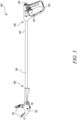
- FIG. 1 illustrates a tool 100 according to an exemplary embodiment of the present invention.
- the tool 100 includes a handle 102 and a pole 104 rotatably coupled to the handle 102.
- the handle 102 may be made of a material including plastic or steel.
- the pole 104 has a first end 106 proximate to the handle 102 and a second end 108 distal from the handle 102.
- the pole 104 extends from the handle 102 from the first end 106 towards the second end 108 along a central pole axis PA (shown in FIG. 5 ).
- the pole 104 may be made of a material including plastic or steel.
- the pole 104 may have a circular cross section.
- the tool 100 further includes an implement 110 fixed to the second end 108 of the pole 104.
- the implement 110 is a gripper or a pincer used to pick up an object (e.g., waste) from the floor, top shelf, outdoor lawn, trash can, behind furniture, or other hard to reach places.
- the tool 100 including the implement 110 may increase the reach of a user to pick or grab various items at a distance.
- the implement 110 includes a pair of gripping members or claws 112 adapted to grab the objects.
- the implement 110 is shown in a deactivated configuration C1 as the pair of gripping members is open.
- the implement 110 is shown in a first position P1 .
- the implement 110 may be removably connected to the second end 108 of the pole 104.
- the pole 104 is adapted to rotate about the central pole axis PA , which will be discussed later in detail.
- FIG. 2 illustrates the tool 100 according to an exemplary embodiment of the present invention, wherein the implement 110 is shown in an activated configuration C2 as the pair of the gripping members 112 is closed.
- the tool 100 may be used as the gripper to pick various objects or items.
- the implement 110 is shown again in the first position P1. Referring to FIG. 1 and FIG. 2 , there is no relative rotation between the handle 102 and the pole 104.
- the handle 102 includes an operating means 124 to activate a functionality of the implement 110.
- the operating means 124 allows the user to activate the functionality of the implement 110 when required.
- the operating means 124 may ease the user's task of deactivating or activating the functionality of the implement 110.
- the operating means 124 is a trigger which the user can control to activate or deactivate the functionality of the implement 110.
- the user may press the operating means 124 to switch the implement 110 from the deactivated configuration C1 (shown in FIG. 1 ) to the activated configuration C2 (shown in FIG. 2 ).
- the user may control the operating means 124 with his/her index finger. In FIG. 2 , the operating means 124 is shown as being pressed.
- FIG. 3 illustrates the tool 100 according to an exemplary embodiment of the present invention, wherein the implement 110 is shown in the deactivated configuration C1 and a second position P2 different from the first position P1 (shown in FIG. 1 ).
- the implement 110 is switched between the first position P1 and the second position P2 due to relative rotation between the handle 102 and the pole 104.
- the implement 110 is switched between the first position P1 and the second position P2 due to the rotation of the pole 104 with respect to the handle 102.
- FIG. 4 illustrates the tool 100 according to an exemplary embodiment of the present invention, wherein the implement 110 is shown in the deactivated configuration C1 and a third position P3 different from each of the first position P1 (shown in FIG. 1 ) and the second position P2 (shown in FIG. 3 ).
- the implement 110 is switched between the first position P1 and the third position P3 due to relative rotation between the handle 102 and the pole 104.
- the implement 110 is switched between the first position P1 and the third position P3 due to the rotation of the pole 104 with respect to the handle 102.
- the implement 110 can be switched between the second position P2 (shown in FIG. 3 ) and the third position P3 due to the rotation of the pole 104 with respect to the handle 102.
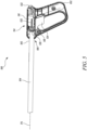
- FIG. 5 illustrates a partial cross sectional side view of the tool 100 according to an exemplary embodiment of the present invention.
- the implement 110 is not shown in FIG. 5 for illustrative purposes.
- the tool 100 further includes a fixation mechanism 114 for coupling the handle 102 and the pole 104 together.
- the fixation mechanism 114 includes a first coupling element 116 associated with the handle 102.
- the first coupling element 116 may be in contact with the handle 102.
- the first coupling element 116 may be connected to the handle 102.
- the first coupling element 116 includes a pair of protrusions 132 circumferentially spaced apart from each other and adapted to engage with the handle 102 upon rotation of the handle 102 about the central pole axis PA. This means that the pair of protrusions 132 limit the rotation of the handle 102 about the central pole axis PA.
- the fixation mechanism 114 further includes a second coupling element 118 associated with an outer surface 105 of the pole 104 , such that the first coupling element 116 and the second coupling element 118 are adapted to be selectively engaged together to couple the handle 102 and the pole 104.
- the second coupling element 118 may be in contact with the first end 106 of the pole 104.
- the second coupling element 118 may be connected to the pole 104.
- the fixation mechanism 114 further includes an elastic member 120 coupled with the pole 104 such that the elastic member 120 cooperates with the first coupling element 116 to force the first coupling element 116 to engage with the second coupling element 118 to rotatably couple the handle 102 and the pole 104 together.
- the elastic member 120 may be a coil spring. In the absence of any external load on the elastic member 120 , the elastic member 120 exerts a biasing force on the first coupling element 116 such that the first coupling element 116 engages with the second coupling element 118 in order to rotatably couple the handle 102 and the pole 104 together.
- the pole 104 When the first coupling element 116 is engaged with the second coupling element 118 , the pole 104 cannot be rotated relative to the handle 102 as the pair of protrusions 132 may contact a portion of the handle 102 and limit the rotation of the handle 102. Therefore, for the relative rotation of the pole 104 and the handle 102 , the first coupling element 116 must be disengaged from the second coupling element 118.
- FIG. 6 illustrates another partial cross sectional side view of the tool 100 according to an exemplary embodiment of the present invention.
- the implement 110 and the operating means 124 are not shown in FIG. 6 for illustrative purposes.
- the handle 102 includes a movable button 122 adapted to allow the first coupling element 116 to act against the elastic member 120 to disengage the rotatable coupling of the handle 102 and the pole 104.
- the button 122 extends at least partially outside the handle 102 when the button 122 is not pressed by the user.
- FIG. 7 illustrates a partial cross-sectional side view of the tool 100 of FIG. 6 , wherein the button 122 is shown as being pressed, in accordance with an exemplary embodiment of the present disclosure.
- the button 122 exerts a force against the biasing force of the elastic member 120 so as to disengage the first coupling element 116 from the second coupling element 118.
- the rotatable coupling between the handle 102 and the pole 104 is disengaged.
- the button 122 may be made of plastic.
- the first coupling element 116 is integral to the button 122. This means that the first coupling element 116 is a part of the button 122. This may reduce the cost of manufacturing the first coupling element 116.
- FIG. 8 illustrates a partial cross-sectional side view of the tool 100 of FIG. 6 from another angle, in accordance with an exemplary embodiment of the present disclosure.
- the button 122 acts on the first coupling element 116 by surpassing the second coupling element 118 from the outside of the second coupling element 118.
- the first coupling element 116 and the second coupling element 118 are adapted to slide relative to each other in a direction parallel to the central pole axis PA such that the first coupling element 116 at least partially encloses the second coupling element 118 while engaging with the second coupling element 118.
- the button 122 when the button 122 is pressed by the user, the first coupling element 116 slides relative to the second coupling element 118 along the central pole axis PA and exerts the force to compress the elastic member 120.
- FIG. 9 illustrates a partial cross-sectional side view of the tool 100 of FIG. 8 , wherein the button 122 is shown as being pressed, in accordance with an exemplary embodiment of the present disclosure.
- the elastic member 120 is not shown in FIG. 9 for illustrative purposes.
- the tool 100 is characterized in that the button 122 acts on the first coupling element 116 by surpassing the second coupling element 118 from the outside of the second coupling element 118.
- the first coupling element 116 and the second coupling element 118 slide relative to each other in a direction parallel to the central pole axis PA such that the first coupling element 116 at least partially encloses the second coupling element 118 while engaging with the second coupling element 118.
- the button 122 is pressed by the user, the first coupling element 116 slides relative to the second coupling element 118 along the central pole axis PA and exerts the force to compress the elastic member 120.
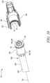
- FIG. 10 illustrates an exploded view of the fixation mechanism 114 of the tool 100 of FIG. 1 , in accordance with an exemplary embodiment of the present disclosure.
- the first coupling element 116 includes a first gear G1.
- the first gear G1 includes first teeth T1 defined on an internal surface of the first coupling element 116.
- the second coupling element 118 includes a second gear G2 adapted to engage with the first gear G1 to rotatably couple the handle 102 and the pole 104.
- the second gear G2 includes second teeth T2 defined on an outer surface of the second coupling element 118.
- the first gear G1 When the button 122 is not pressed by the user, the first gear G1 is meshed with the second gear G2 and thereby prevents rotation of the pole 104 relative to the handle 102.
- the first coupling element 116 slides against the biasing force of the elastic member 120 and the first gear G1 is disengaged from the second gear G2 so as to allow the rotation of the pole 104 relative to the handle 102. Therefore, engagement and disengagement between the first gear G1 and the second gear G2 allows the user to rotate the pole 104 relative to the handle 102 in accordance with the application requirements.
- inclusion of the first gear G1 and the second gear G2 may provide convenience to the user for using the tool 100 in the different positions (i.e., the first position P1 , the second position P2 , and so on) of the implement 110.
- FIG. 11 illustrates a partial exploded view of the tool 100 of FIG. 1 , in accordance with an exemplary embodiment of the present disclosure.
- the pole 104 encloses one or more mechanical elements 126 , such that the one or more mechanical elements 126 allow a mechanical activation.
- the one or more mechanical elements 126 may allow mechanical activation or deactivation of the functionality of the implement 110 based on a configuration of the operating means 124 .
- the one or more mechanical elements 126 may allow a transfer of mechanical energy from the operating means 124 to the implement 110 , and therefore, may facilitate activation or deactivation of the functionality of the implement 110.
- the one or more mechanical elements 126 include an internal cable 128 , a washer 130 , and so on.
- the cable 128 may transfer mechanical motion (i.e., energy) between the operating means 124 and the implement 110.
- the present disclosure provides the tool 100 that is simple in design and convenient to use.
- the user can press the movable button 122 to allow the first coupling element 116 to act against the elastic member 120 to disengage the rotatable coupling of the handle 102 and the pole 104 , and this allows the rotation of the pole 104 relative to the handle 102.
- different positions i.e., the first position P1 , the second position P2 , the third position P3 , and so on
- different positions i.e., the first position P1 , the second position P2 , the third position P3 , and so on
- the implement 110 may be selected based on application and user requirements.
- the pole 104 cannot be rotated relative to the handle 102.
- the tool 100 of the present disclosure does not require any clamping nuts which were used in conventional tools. This may provide the user with an ease to shift the implement position in accordance with the application attributes.
- the mechanical arrangement between the handle 102 , the first coupling element 116 , the second coupling element 118 , and the elastic member 120 is such that the pole 104 can be easily rotated relative to the handle 102 and the tool 100 of the present disclosure may be used efficiently and effectively in the different positions of the implement 110.
Landscapes
- Engineering & Computer Science (AREA)
- Mechanical Engineering (AREA)
- Robotics (AREA)
- Details Of Spanners, Wrenches, And Screw Drivers And Accessories (AREA)
Abstract
A tool (100) includes a handle (102) and a pole (104) extending from the handle (102) from a first end (106) towards a second end (108) along a central pole axis (PA). The tool (100) includes an implement (110). The tool (100) further includes a fixation mechanism (114) for coupling the handle (102) and the pole (104) together. The fixation mechanism (114) includes a first coupling element (116) associated with the handle (102), and a second coupling element (118) associated with an outer surface (105) of the pole. The first coupling element (116) and the second coupling element (118) are adapted to be selectively engaged together. An elastic member (120) coupled with the pole cooperates with the first coupling element (116) to force the first coupling element (116) to engage with the second coupling element (118) to rotatably couple the handle (102) and the pole (104) together. The handle (102) includes a movable button (122) to allow the first coupling element (116) to act against the elastic member (120) to disengage the rotatable coupling of the handle (102) and the pole (104).
Description
- The present disclosure relates to a tool. More specifically, the present disclosure relates to the tool, preferably a gripper, with a rotatable handle.
- A gripper or a pincer is a tool that may be used to pick up an object (e.g., waste) from the floor, top shelf, outdoor lawn, trash can, behind furniture, or other hard to reach places. The gripper is designed specifically to increase the reach of a user. In some applications, the gripper may help a user to avoid back pain which can otherwise occur while picking an object from the floor without the gripper. The gripper is handy and portable.
- Such handheld tools (e.g., gripper) usually include a grip trigger handle and a pole with an implement (e.g., claws) at its end opposite to the handle. In case of grippers with asymmetric working head, there is a need to have rotatable handle bars or poles as it enables to work with different gripper or pincers positions. For efficient and effective operations of a gripper, different applications require corresponding different positions of the implement relative to the handle. Some designs of the grippers or the pincers utilize clamping nuts to provide rotatable handle bars. However, such provision is not so easy and convenient to use due to locking and unlocking of the clamping nuts so as to rotate the handle bar.
- An example of a handle rotation mechanism in a lopper saw (high branch saw) is provided in Chinese utility model
CN 202 680 050 U . The '050 reference describes a lopper saw that exhibits a handle connected to a pole that carries a chain saw on the other side. The handle as well as the pole exhibits a locking mechanism with interacting teeth. The handle and pole are rotationally fixed via a spring force acting between the handle and its movable locking structure. The movable locking structure incorporates a button reaching through the center of the locking structure associated with the pole. The pressing of this button acts against the spring force and thus releases the interaction of the locking structures, which in turn allows to rotate the handle against the pole. - In view of the above, it is an objective of the present invention to solve or at least reduce the drawbacks discussed above. The objective is at least partially achieved by a tool having an easy to use and convenient rotatable coupling between a handle and a pole of the tool.
- According to an aspect of the present invention, the tool includes a handle. The tool further includes a pole rotatably coupled to the handle. The pole has a first end proximate to the handle and a second end distal from the handle such that the pole extends from the handle from the first end towards the second end along a central pole axis. The tool further includes an implement fixed to the second end of the pole. The tool further includes a fixation mechanism for coupling the handle and the pole together. The fixation mechanism includes a first coupling element associated with the handle. The fixation mechanism further includes a second coupling element associated with an outer surface of the pole, such that the first coupling element and the second coupling element are adapted to be selectively engaged together to couple the handle and the pole. The fixation mechanism further includes an elastic member coupled with the pole such that the elastic member cooperates with the first coupling element to force the first coupling element to engage with the second coupling element to rotatably couple the handle and the pole together. The handle further includes a movable button adapted to allow the first coupling element to act against the elastic member to disengage the rotatable coupling of the handle and the pole. The tool is characterized in that the button acts on the first coupling element by surpassing the second coupling element from the outside of the second coupling element. The first coupling element and the second coupling element are adapted to slide relative to each other in a direction parallel to the central pole axis such that the first coupling element at least partially encloses the second coupling element while engaging with the second coupling element.
- Thus, the present disclosure provides a tool that is simple in design and convenient to use. A user can press the movable button to allow the first coupling element to act against the elastic member to disengage the rotatable coupling of the handle and the pole, and therefore this allows the rotation of the pole relative to the handle. In this way, different positions of the implement may be selected based on application and user requirements. As long as the elastic member cooperates with the first coupling element to force the first coupling element to engage with the second coupling element to rotatably couple the handle and the pole together, the pole cannot be rotated relative to the handle. Moreover, for rotating the pole relative to the handle, the tool of the present disclosure does not require any clamping nuts which were used in conventional tools. This may provide the users an ease to shift the implement position in accordance with the application attributes. Hence, the mechanical arrangement between the handle, the first coupling element, the second coupling element, and the elastic member is such that the pole can be easily rotated relative to the handle and the tool of the present disclosure may be used efficiently and effectively in the different positions of the implement. In particular by surpassing the second coupling element by the first coupling element the center of the second coupling element is mechanically unaffected and can independent of the first coupling element mechanically designed according the needs. For example mechanical lines running inside the pole between the implement and an operating means associated with the handle can be designed independent of the fixation mechanism.
- According to an exemplary embodiment of the invention, the implement may be removably connected to the second end of the pole. The implement may be a saw blade cutting mechanism, gripping claws, and so on. A user may select the implement based on the required application. Different positions of the implement can be equipped by rotating the pole relative to the handle and improve work efficiency. The implement may be made of steel, brass, or aluminum. However, other materials may also be used to manufacture the implement based on application requirements.
- According to an exemplary embodiment of the invention, the first coupling element may be in contact with the handle. The first coupling element may be connected to the handle. The first coupling element may be integral to the handle. This means that the first coupling element may be a part of the handle.
- According to an exemplary embodiment of the invention, the second coupling element may be in contact with the first end of the pole. The second coupling element may be connected to the pole. The second coupling element may be integral to the pole. This means that the second coupling element may be a part or an extension of the pole.
- According to an exemplary embodiment of the invention, the elastic member may be a coil spring. The coil spring may be a helical spring. In the absence of any external load on the elastic member, the elastic member exerts a biasing force on the first coupling element such that the first coupling element engages with the second coupling element in order to rotatably couple the handle and the pole together.
- According to an exemplary embodiment of the invention, the button may extend at least partially outside the handle when the button is not pressed by the user. Upon being pressed by the user, the button exerts a force against the biasing force of the elastic member so as to disengage the first coupling element from the second coupling element. As a result of the disengagement of the first coupling element from the second coupling element, the rotatable coupling between the handle and the pole is disengaged. The button may be made of plastic. In an application, instead of the button, the handle may include a knob or a lever.
- According to an exemplary embodiment of the invention, the handle includes an operating means to activate a functionality of the implement. The operating means allows the user to activate the functionality of the implement when required. The operating means may ease the user's task of deactivating or activating the functionality of the implement.
- According to an exemplary embodiment of the invention, the operating means may include a trigger which the user can control to activate or deactivate the functionality of the implement. The button and the operating means may be angularly spaced apart from each other with respect to the central pole axis. The user may control the operating means with his/her index finger.
- According to an exemplary embodiment of the invention, the pole encloses one or more mechanical elements, such that the one or more mechanical elements allow a mechanical activation. The one or more mechanical elements may allow mechanical activation or deactivation of the functionality of the implement based on a configuration of the operating means. The one or more mechanical elements may allow a transfer of mechanical energy from the operating means to the implement, and therefore, may facilitate activation or deactivation of the functionality of the implement.
- According to an exemplary embodiment of the invention, the one or more mechanical elements may include an internal cable (i.e., a wire), a washer, and so on. The cable may be made of, but not limited to, steel for durability and ease of use. The cable may transfer mechanical motion (i.e., energy) between the operating means and the implement.
- According to an exemplary embodiment of the invention, the first coupling element includes a first gear. When the button is not pressed by the user, the first gear is engaged with the second coupling element and thereby prevents rotation of the pole relative to the handle. When the button is pressed by the user, the first gear acts against the biasing force of the elastic member and is disengaged from the second coupling element so as to allow the rotation of the pole relative to the handle.
- According to an exemplary embodiment of the invention, the first gear includes first teeth. The first teeth may be defined on an internal surface of the first coupling element. The first teeth may be adapted to engage with the second coupling element in order to rotatably couple the handle and the pole together. The first gear may include, instead of the first teeth, any other locking or engaging structure. The first gear may be made of a material comprising plastic or metal.
- According to an exemplary embodiment of the invention, the second coupling element includes a second gear adapted to engage with the first gear to rotatably couple the handle and the pole. When the button is not pressed by the user, the first gear is meshed with the second gear and thereby prevents rotation of the pole relative to the handle. When the button is pressed by the user, the first coupling element slides against the biasing force of the elastic member and the first gear is disengaged from the second gear so as to allow the rotation of the pole relative to the handle. Therefore, engagement and disengagement between the first gear and the second gear allows the user to rotate the pole relative to the handle in accordance with the application requirements. In this way, inclusion of the first gear and the second gear may provide convenience to the user for using the tool in the different positions of the implement.
- According to an exemplary embodiment of the invention, the second gear includes second teeth. The second teeth may be defined on an outer surface of the second coupling element. The second teeth may be adapted to engage with the first coupling element in order to rotatably couple the handle and the pole together. The second gear may include, instead of the second teeth, any other locking or engaging structure. The second gear may be made of a material comprising plastic or metal.
- According to an exemplary embodiment of the invention, the pole is adapted to rotate about the central pole axis. The rotation of the pole about the central pole axis allows the implement to be operated in different positions with respect to the handle. The pole, the elastic member, the first coupling element, and the second coupling element are coaxially arranged to each other.
- According to an exemplary embodiment of the invention, the first coupling element is integral to the button. This means that the first coupling element is a part of the button. This may reduce the cost of manufacturing the first coupling element.
- According to an exemplary embodiment of the invention, the first coupling element includes a pair of protrusions circumferentially spaced apart from each other and adapted to engage with the handle upon rotation of the handle about the central pole axis. The pair of protrusions may limit the rotation of the handle about the central pole axis.
- According to an exemplary embodiment of the invention, the pair of protrusions may extend along the central pole axis. The pair of protrusions may be disposed opposite to each other. The pair of protrusions may be disposed on an external surface of the first coupling element.
- Before discussing the invention with the help of the drawings, the invention will be briefly discussed in general. A tool is disclosed which may provide a means for using an implement in different positions (i.e., angular positions). A user may choose a desirable position of the implement based on his/her comfort and application attributes. The tool includes components, such as the first coupling element, the second coupling element, and the elastic member to rotatably couple the handle and the pole together. This rotatable coupling between the handle and the pole allows a relative rotation between the handle and the pole, and thereby change the position of the implement without changing the position of the handle.
- Other features and aspects of this invention will be apparent from the following description and the accompanying drawings.
- The invention will be described in more detail with reference to the enclosed drawings, wherein:
-
FIG. 1 illustrates a perspective side view of a tool including an implement shown in a deactivated configuration, in accordance with an exemplary embodiment of the present disclosure; -
FIG. 2 illustrates a perspective side view of the tool ofFIG. 1 including the implement shown in an activated configuration, in accordance with an exemplary embodiment of the present disclosure; -
FIG. 3 illustrates a perspective side view of the tool ofFIG. 1 , wherein the implement is shown in a position different than that of the position shown inFIG. 1 , in accordance with an exemplary embodiment of the present disclosure; -
FIG. 4 illustrates a perspective side view of the tool ofFIG. 1 , wherein the implement is shown in a position different than that of the positions shown inFIGS. 1 and3 , in accordance with an exemplary embodiment of the present disclosure; -
FIG. 5 illustrates a partial cross-sectional side view of the tool ofFIG. 1 , in accordance with an exemplary embodiment of the present disclosure; -
FIG. 6 illustrates a partial cross-sectional side view of the tool ofFIG. 5 , with some components not shown, in accordance with an exemplary embodiment of the present disclosure; -
FIG. 7 illustrates a partial cross-sectional side view of the tool ofFIG. 6 , wherein a button of the tool is shown as being pressed, in accordance with an exemplary embodiment of the present disclosure; -
FIG. 8 illustrates a partial cross-sectional side view of the tool ofFIG. 6 from another angle, in accordance with an exemplary embodiment of the present disclosure; -
FIG. 9 illustrates a partial cross-sectional side view of the tool ofFIG. 8 , wherein the button of the tool is shown as being pressed, in accordance with an exemplary embodiment of the present disclosure; -
FIG. 10 illustrates an exploded view of a fixation mechanism of the tool ofFIG. 1 , in accordance with an exemplary embodiment of the present disclosure; and -
FIG. 11 illustrates a partial exploded view of the tool ofFIG. 1 , in accordance with an exemplary embodiment of the present disclosure. - The present invention will be described more fully hereinafter with reference to the accompanying drawings, in which example embodiments of the invention incorporating one or more aspects of the present invention are shown. This invention may, however, be embodied in many different forms and should not be construed as limited to the embodiments set forth herein; rather, these embodiments are provided so that this disclosure will be thorough and complete, and will fully convey the scope of the invention to those skilled in the art. For example, one or more aspects of the present invention may be utilized in other embodiments and even other types of structures and/or methods. In the drawings, like numbers refer to like elements.
- Certain terminology is used herein for convenience only and is not to be taken as a limitation on the invention. For example, "upper", "lower", "front", "rear", "side", "longitudinal", "lateral", "transverse", "upwards", "downwards", "forward", "backward", "sideward", "left," "right," "horizontal," "vertical," "upward", "inner", "outer", "inward", "outward", "top", "bottom", "higher", "above", "below", "central", "middle", "intermediate", "between", "end", "adjacent", "proximate", "near", "distal", "remote", "radial", "circumferential", or the like, merely describe the configuration shown in the Figures. Indeed, the components may be oriented in any direction and the terminology, therefore, should be understood as encompassing such variations unless specified otherwise.
-
FIG. 1 illustrates atool 100 according to an exemplary embodiment of the present invention. Thetool 100 includes ahandle 102 and apole 104 rotatably coupled to thehandle 102. Thehandle 102 may be made of a material including plastic or steel. Thepole 104 has afirst end 106 proximate to thehandle 102 and asecond end 108 distal from thehandle 102. Thepole 104 extends from thehandle 102 from thefirst end 106 towards thesecond end 108 along a central pole axis PA (shown inFIG. 5 ). Thepole 104 may be made of a material including plastic or steel. Thepole 104 may have a circular cross section. - The
tool 100 further includes an implement 110 fixed to thesecond end 108 of thepole 104. In the illustrated embodiment ofFIG. 1 , the implement 110 is a gripper or a pincer used to pick up an object (e.g., waste) from the floor, top shelf, outdoor lawn, trash can, behind furniture, or other hard to reach places. Thetool 100 including the implement 110 may increase the reach of a user to pick or grab various items at a distance. The implement 110 includes a pair of gripping members orclaws 112 adapted to grab the objects. InFIG. 1 , the implement 110 is shown in a deactivated configuration C1 as the pair of gripping members is open. Further, inFIG. 1 , the implement 110 is shown in a first position P1. The implement 110 may be removably connected to thesecond end 108 of thepole 104. According to an exemplary embodiment, thepole 104 is adapted to rotate about the central pole axis PA, which will be discussed later in detail. -
FIG. 2 illustrates thetool 100 according to an exemplary embodiment of the present invention, wherein the implement 110 is shown in an activated configuration C2 as the pair of the grippingmembers 112 is closed. In the activated configuration C2 of the implement 110, thetool 100 may be used as the gripper to pick various objects or items. InFIG. 2 , the implement 110 is shown again in the first position P1. Referring toFIG. 1 andFIG. 2 , there is no relative rotation between thehandle 102 and thepole 104. - According to an exemplary embodiment, the
handle 102 includes an operating means 124 to activate a functionality of the implement 110. The operating means 124 allows the user to activate the functionality of the implement 110 when required. The operating means 124 may ease the user's task of deactivating or activating the functionality of the implement 110. The operating means 124 is a trigger which the user can control to activate or deactivate the functionality of the implement 110. For example, the user may press the operating means 124 to switch the implement 110 from the deactivated configuration C1 (shown inFIG. 1 ) to the activated configuration C2 (shown inFIG. 2 ). The user may control the operating means 124 with his/her index finger. InFIG. 2 , the operating means 124 is shown as being pressed. -
FIG. 3 illustrates thetool 100 according to an exemplary embodiment of the present invention, wherein the implement 110 is shown in the deactivated configuration C1 and a second position P2 different from the first position P1 (shown inFIG. 1 ). Referring toFIG. 1 andFIG. 3 , it can be concluded that the implement 110 is switched between the first position P1 and the second position P2 due to relative rotation between thehandle 102 and thepole 104. Specifically, the implement 110 is switched between the first position P1 and the second position P2 due to the rotation of thepole 104 with respect to thehandle 102. -
FIG. 4 illustrates thetool 100 according to an exemplary embodiment of the present invention, wherein the implement 110 is shown in the deactivated configuration C1 and a third position P3 different from each of the first position P1 (shown inFIG. 1 ) and the second position P2 (shown inFIG. 3 ). Referring toFIG. 1 andFIG. 4 , it can be concluded that the implement 110 is switched between the first position P1 and the third position P3 due to relative rotation between thehandle 102 and thepole 104. Specifically, the implement 110 is switched between the first position P1 and the third position P3 due to the rotation of thepole 104 with respect to thehandle 102. Moreover, the implement 110 can be switched between the second position P2 (shown inFIG. 3 ) and the third position P3 due to the rotation of thepole 104 with respect to thehandle 102. -
FIG. 5 illustrates a partial cross sectional side view of thetool 100 according to an exemplary embodiment of the present invention. The implement 110 is not shown inFIG. 5 for illustrative purposes. Thetool 100 further includes afixation mechanism 114 for coupling thehandle 102 and thepole 104 together. Thefixation mechanism 114 includes afirst coupling element 116 associated with thehandle 102. Thefirst coupling element 116 may be in contact with thehandle 102. Thefirst coupling element 116 may be connected to thehandle 102. - According to an exemplary embodiment, the
first coupling element 116 includes a pair ofprotrusions 132 circumferentially spaced apart from each other and adapted to engage with thehandle 102 upon rotation of thehandle 102 about the central pole axis PA. This means that the pair ofprotrusions 132 limit the rotation of thehandle 102 about the central pole axis PA. - The
fixation mechanism 114 further includes asecond coupling element 118 associated with anouter surface 105 of thepole 104, such that thefirst coupling element 116 and thesecond coupling element 118 are adapted to be selectively engaged together to couple thehandle 102 and thepole 104. Thesecond coupling element 118 may be in contact with thefirst end 106 of thepole 104. Thesecond coupling element 118 may be connected to thepole 104. - The
fixation mechanism 114 further includes anelastic member 120 coupled with thepole 104 such that theelastic member 120 cooperates with thefirst coupling element 116 to force thefirst coupling element 116 to engage with thesecond coupling element 118 to rotatably couple thehandle 102 and thepole 104 together. Theelastic member 120 may be a coil spring. In the absence of any external load on theelastic member 120, theelastic member 120 exerts a biasing force on thefirst coupling element 116 such that thefirst coupling element 116 engages with thesecond coupling element 118 in order to rotatably couple thehandle 102 and thepole 104 together. - When the
first coupling element 116 is engaged with thesecond coupling element 118, thepole 104 cannot be rotated relative to thehandle 102 as the pair ofprotrusions 132 may contact a portion of thehandle 102 and limit the rotation of thehandle 102. Therefore, for the relative rotation of thepole 104 and thehandle 102, thefirst coupling element 116 must be disengaged from thesecond coupling element 118. -
FIG. 6 illustrates another partial cross sectional side view of thetool 100 according to an exemplary embodiment of the present invention. The implement 110 and the operating means 124 are not shown inFIG. 6 for illustrative purposes. Thehandle 102 includes amovable button 122 adapted to allow thefirst coupling element 116 to act against theelastic member 120 to disengage the rotatable coupling of thehandle 102 and thepole 104. Thebutton 122 extends at least partially outside thehandle 102 when thebutton 122 is not pressed by the user. -
FIG. 7 illustrates a partial cross-sectional side view of thetool 100 ofFIG. 6 , wherein thebutton 122 is shown as being pressed, in accordance with an exemplary embodiment of the present disclosure. Upon being pressed by the user, thebutton 122 exerts a force against the biasing force of theelastic member 120 so as to disengage thefirst coupling element 116 from thesecond coupling element 118. As a result of the disengagement of thefirst coupling element 116 from thesecond coupling element 118, the rotatable coupling between thehandle 102 and thepole 104 is disengaged. Thebutton 122 may be made of plastic. - According to an exemplary embodiment of the invention, the
first coupling element 116 is integral to thebutton 122. This means that thefirst coupling element 116 is a part of thebutton 122. This may reduce the cost of manufacturing thefirst coupling element 116. -
FIG. 8 illustrates a partial cross-sectional side view of thetool 100 ofFIG. 6 from another angle, in accordance with an exemplary embodiment of the present disclosure. Thebutton 122 acts on thefirst coupling element 116 by surpassing thesecond coupling element 118 from the outside of thesecond coupling element 118. Thefirst coupling element 116 and thesecond coupling element 118 are adapted to slide relative to each other in a direction parallel to the central pole axis PA such that thefirst coupling element 116 at least partially encloses thesecond coupling element 118 while engaging with thesecond coupling element 118. In other words, when thebutton 122 is pressed by the user, thefirst coupling element 116 slides relative to thesecond coupling element 118 along the central pole axis PA and exerts the force to compress theelastic member 120. -
FIG. 9 illustrates a partial cross-sectional side view of thetool 100 ofFIG. 8 , wherein thebutton 122 is shown as being pressed, in accordance with an exemplary embodiment of the present disclosure. Theelastic member 120 is not shown inFIG. 9 for illustrative purposes. Thetool 100 is characterized in that thebutton 122 acts on thefirst coupling element 116 by surpassing thesecond coupling element 118 from the outside of thesecond coupling element 118. Thefirst coupling element 116 and thesecond coupling element 118 slide relative to each other in a direction parallel to the central pole axis PA such that thefirst coupling element 116 at least partially encloses thesecond coupling element 118 while engaging with thesecond coupling element 118. When thebutton 122 is pressed by the user, thefirst coupling element 116 slides relative to thesecond coupling element 118 along the central pole axis PA and exerts the force to compress theelastic member 120. -
FIG. 10 illustrates an exploded view of thefixation mechanism 114 of thetool 100 ofFIG. 1 , in accordance with an exemplary embodiment of the present disclosure. Thefirst coupling element 116 includes a first gear G1. The first gear G1 includes first teeth T1 defined on an internal surface of thefirst coupling element 116. Thesecond coupling element 118 includes a second gear G2 adapted to engage with the first gear G1 to rotatably couple thehandle 102 and thepole 104. The second gear G2 includes second teeth T2 defined on an outer surface of thesecond coupling element 118. - When the
button 122 is not pressed by the user, the first gear G1 is meshed with the second gear G2 and thereby prevents rotation of thepole 104 relative to thehandle 102. When thebutton 122 is pressed by the user, thefirst coupling element 116 slides against the biasing force of theelastic member 120 and the first gear G1 is disengaged from the second gear G2 so as to allow the rotation of thepole 104 relative to thehandle 102. Therefore, engagement and disengagement between the first gear G1 and the second gear G2 allows the user to rotate thepole 104 relative to thehandle 102 in accordance with the application requirements. In this way, inclusion of the first gear G1 and the second gear G2 may provide convenience to the user for using thetool 100 in the different positions (i.e., the first position P1, the second position P2, and so on) of the implement 110. -
FIG. 11 illustrates a partial exploded view of thetool 100 ofFIG. 1 , in accordance with an exemplary embodiment of the present disclosure. Thepole 104 encloses one or more mechanical elements 126, such that the one or more mechanical elements 126 allow a mechanical activation. The one or more mechanical elements 126 may allow mechanical activation or deactivation of the functionality of the implement 110 based on a configuration of the operating means 124. The one or more mechanical elements 126 may allow a transfer of mechanical energy from the operating means 124 to the implement 110, and therefore, may facilitate activation or deactivation of the functionality of the implement 110. The one or more mechanical elements 126 include an internal cable 128, a washer 130, and so on. The cable 128 may transfer mechanical motion (i.e., energy) between the operating means 124 and the implement 110. - The present disclosure provides the
tool 100 that is simple in design and convenient to use. The user can press themovable button 122 to allow thefirst coupling element 116 to act against theelastic member 120 to disengage the rotatable coupling of thehandle 102 and thepole 104, and this allows the rotation of thepole 104 relative to thehandle 102. In this way, different positions (i.e., the first position P1, the second position P2, the third position P3, and so on) of the implement 110 may be selected based on application and user requirements. As long as theelastic member 120 cooperates with thefirst coupling element 116 to force thefirst coupling element 116 to engage with thesecond coupling element 118 to rotatably couple thehandle 102 and thepole 104 together, thepole 104 cannot be rotated relative to thehandle 102. Moreover, for rotating thepole 104 relative to thehandle 102, thetool 100 of the present disclosure does not require any clamping nuts which were used in conventional tools. This may provide the user with an ease to shift the implement position in accordance with the application attributes. Hence, the mechanical arrangement between thehandle 102, thefirst coupling element 116, thesecond coupling element 118, and theelastic member 120 is such that thepole 104 can be easily rotated relative to thehandle 102 and thetool 100 of the present disclosure may be used efficiently and effectively in the different positions of the implement 110. - In the drawings and specification, there have been disclosed preferred embodiments and examples of the invention and, although specific terms are employed, they are used in a generic and descriptive sense only and not for the purpose of limitation of the scope of the invention being set forth in the following claims.
-
- 100
- Tool
- 102
- Handle
- 104
- Pole
- 106
- First End
- 108
- Second End
- 105
- Outer Surface
- 110
- Implement
- 112
- Gripping Members
- 114
- Fixation Mechanism
- 116
- First Coupling Element
- 118
- Second Coupling Element
- 120
- Elastic Member
- 122
- Button
- 124
- Operating Means
- 126
- Mechanical Element
- 128
- Cable
- 130
- Washer
- 132
- Protrusion
- PA
- Central Pole Axis
- G1
- First Gear
- G2
- Second Gear
- T1
- First Teeth
- T2
- Second Teeth
- C1
- Deactivated Configuration
- C2
- Activated Configuration
- P1
- First Position
- P2
- Second Position
- P3
- Third Position
Claims (8)
- A tool (100) comprising:a handle (102);a pole (104) rotatably coupled to the handle (102), wherein the pole (104) has a first end (106) proximate to the handle (102) and a second end (108) distal from the handle (102) such that the pole (104) extends from the handle (102) from the first end (106) towards the second end (108) along a central pole axis (PA);an implement (110) fixed to the second end (108) of the pole (104);a fixation mechanism (114) for coupling the handle (102) and the pole (104) together, the fixation mechanism (114) comprising:characterized in that:a first coupling element (116) associated with the handle (102);a second coupling element (118) associated with an outer surface (105) of the pole (104), such that the first coupling element (116) and the second coupling element (118) are adapted to be selectively engaged together to couple the handle (102) and the pole (104);an elastic member (120) coupled with the pole (104) such that the elastic member (120) cooperates with the first coupling element (116) to force the first coupling element (116) to engage with the second coupling element (118) to rotatably couple the handle (102) and the pole (104) together;wherein the handle (102) further comprises a movable button (122) adapted to allow the first coupling element (116) to act against the elastic member (120) to disengage the rotatable coupling of the handle (102) and the pole (104);the button (122) acts on the first coupling element (116) by surpassing the second coupling element (118) from the outside of the second coupling element (118); andthe first coupling element (116) and the second coupling element (118) are adapted to slide relative to each other in a direction parallel to the central pole axis (PA) such that the first coupling element (116) at least partially encloses the second coupling element (118) while engaging with the second coupling element (118).
- The tool (100) of claim 1, wherein the handle (102) comprises an operating means (124) to activate a functionality of the implement (110).
- The tool (100) of claim 2, wherein the pole (104) encloses one or more mechanical elements (126), such that the one or more mechanical elements (126) allow a mechanical activation.
- The tool (100) according to any one of the preceding claims, wherein the first coupling element (116) comprises a first gear (G1).
- The tool (100) of claim 4, wherein the second coupling element (118) comprises a second gear (G2) adapted to engage with the first gear (G1) to rotatably couple the handle (102) and the pole (104).
- The tool (100) according to any one of the preceding claims, wherein the pole (104) is adapted to rotate about the central pole axis (PA).
- The tool (100) according to any one of the preceding claims, wherein the first coupling element (116) is integral to the button (122).
- The tool (100) according to any one of the preceding claims, wherein the first coupling element (116) comprises a pair of protrusions (132) circumferentially spaced apart from each other and adapted to engage with the handle (102) upon rotation of the handle (102) about the central pole axis (PA).
Priority Applications (2)
| Application Number | Priority Date | Filing Date | Title |
|---|---|---|---|
| EP23159504.2A EP4424472A1 (en) | 2023-03-01 | 2023-03-01 | Tool |
| CN202410237534.XA CN118578347A (en) | 2023-03-01 | 2024-03-01 | tool |
Applications Claiming Priority (1)
| Application Number | Priority Date | Filing Date | Title |
|---|---|---|---|
| EP23159504.2A EP4424472A1 (en) | 2023-03-01 | 2023-03-01 | Tool |
Publications (1)
| Publication Number | Publication Date |
|---|---|
| EP4424472A1 true EP4424472A1 (en) | 2024-09-04 |
Family
ID=85570030
Family Applications (1)
| Application Number | Title | Priority Date | Filing Date |
|---|---|---|---|
| EP23159504.2A Pending EP4424472A1 (en) | 2023-03-01 | 2023-03-01 | Tool |
Country Status (2)
| Country | Link |
|---|---|
| EP (1) | EP4424472A1 (en) |
| CN (1) | CN118578347A (en) |
Citations (4)
| Publication number | Priority date | Publication date | Assignee | Title |
|---|---|---|---|---|
| DE1886500U (en) * | 1959-03-05 | 1964-01-23 | Heinrich Kunz | HOLDER FOR KEYS AND TOOL INSERTS. |
| US7540679B2 (en) * | 2002-10-23 | 2009-06-02 | Pentel Kabushiki Kaisha | Variable grip structure |
| EP2100562A2 (en) * | 2008-02-14 | 2009-09-16 | Ethicon Endo-Surgery, Inc. | Surgical stapling apparatus with control features operable with one hand |
| CN202680050U (en) | 2012-05-25 | 2013-01-23 | 浙江亚特电器有限公司 | Lopper saw with handle rotating mechanism |
-
2023
- 2023-03-01 EP EP23159504.2A patent/EP4424472A1/en active Pending
-
2024
- 2024-03-01 CN CN202410237534.XA patent/CN118578347A/en active Pending
Patent Citations (4)
| Publication number | Priority date | Publication date | Assignee | Title |
|---|---|---|---|---|
| DE1886500U (en) * | 1959-03-05 | 1964-01-23 | Heinrich Kunz | HOLDER FOR KEYS AND TOOL INSERTS. |
| US7540679B2 (en) * | 2002-10-23 | 2009-06-02 | Pentel Kabushiki Kaisha | Variable grip structure |
| EP2100562A2 (en) * | 2008-02-14 | 2009-09-16 | Ethicon Endo-Surgery, Inc. | Surgical stapling apparatus with control features operable with one hand |
| CN202680050U (en) | 2012-05-25 | 2013-01-23 | 浙江亚特电器有限公司 | Lopper saw with handle rotating mechanism |
Also Published As
| Publication number | Publication date |
|---|---|
| CN118578347A (en) | 2024-09-03 |
Similar Documents
| Publication | Publication Date | Title |
|---|---|---|
| US6257634B1 (en) | Manual litter picker | |
| AU701864B2 (en) | Pivoted hand tool | |
| EP0940832B1 (en) | Multimate project-a switch lock-off mechanism | |
| EP2254736B1 (en) | Tool including a locking mechanism | |
| US8793886B2 (en) | Power tool with a rotatable working head | |
| EP0982745B1 (en) | Lock out mechanism for power tool | |
| WO2000009298A9 (en) | Remote gripping or cutting apparatus having a rotatable head | |
| US20080244916A1 (en) | Hand-Held Power Tool with a Rod-Shaoed Grip | |
| CN103181262A (en) | Garden tool | |
| US5867910A (en) | Control for portable power tool | |
| EP3858561A1 (en) | Cutting tool | |
| AU2007203183A1 (en) | Power tool with removable handle portion | |
| CN101273694B (en) | Hand-hold operating apparatus | |
| KR101110037B1 (en) | Clamping style handle for kitchen vessel | |
| AU2011101131A4 (en) | Hedge Trimmer And Switch Device Thereof | |
| US20020095796A1 (en) | Scissors with flexible handle segment | |
| CN118578347A (en) | tool | |
| WO1994005465A1 (en) | Handle for a cleaning utensil | |
| EP4424474B1 (en) | Gripper device | |
| EP4118947B1 (en) | Hand-held device | |
| EP4280854B1 (en) | Gardening tool | |
| EP3879965B1 (en) | Cutting tool | |
| EP4280859B1 (en) | Cutting tool | |
| CA2475831C (en) | Drive mechanism for power tool | |
| CN112088634A (en) | Gardening machine |
Legal Events
| Date | Code | Title | Description |
|---|---|---|---|
| PUAI | Public reference made under article 153(3) epc to a published international application that has entered the european phase |
Free format text: ORIGINAL CODE: 0009012 |
|
| STAA | Information on the status of an ep patent application or granted ep patent |
Free format text: STATUS: REQUEST FOR EXAMINATION WAS MADE |
|
| 17P | Request for examination filed |
Effective date: 20231215 |
|
| AK | Designated contracting states |
Kind code of ref document: A1 Designated state(s): AL AT BE BG CH CY CZ DE DK EE ES FI FR GB GR HR HU IE IS IT LI LT LU LV MC ME MK MT NL NO PL PT RO RS SE SI SK SM TR |