EP4424397A1 - System for recovering valuable material from crucible used in production of positive electrode active material - Google Patents
System for recovering valuable material from crucible used in production of positive electrode active material Download PDFInfo
- Publication number
- EP4424397A1 EP4424397A1 EP23211454.6A EP23211454A EP4424397A1 EP 4424397 A1 EP4424397 A1 EP 4424397A1 EP 23211454 A EP23211454 A EP 23211454A EP 4424397 A1 EP4424397 A1 EP 4424397A1
- Authority
- EP
- European Patent Office
- Prior art keywords
- steam
- module
- concentration
- lithium
- unit
- Prior art date
- Legal status (The legal status is an assumption and is not a legal conclusion. Google has not performed a legal analysis and makes no representation as to the accuracy of the status listed.)
- Withdrawn
Links
Images







Classifications
-
- C—CHEMISTRY; METALLURGY
- C22—METALLURGY; FERROUS OR NON-FERROUS ALLOYS; TREATMENT OF ALLOYS OR NON-FERROUS METALS
- C22B—PRODUCTION AND REFINING OF METALS; PRETREATMENT OF RAW MATERIALS
- C22B3/00—Extraction of metal compounds from ores or concentrates by wet processes
- C22B3/20—Treatment or purification of solutions, e.g. obtained by leaching
- C22B3/22—Treatment or purification of solutions, e.g. obtained by leaching by physical processes, e.g. by filtration, by magnetic means, or by thermal decomposition
-
- B—PERFORMING OPERATIONS; TRANSPORTING
- B09—DISPOSAL OF SOLID WASTE; RECLAMATION OF CONTAMINATED SOIL
- B09B—DISPOSAL OF SOLID WASTE NOT OTHERWISE PROVIDED FOR
- B09B3/00—Destroying solid waste or transforming solid waste into something useful or harmless
- B09B3/40—Destroying solid waste or transforming solid waste into something useful or harmless involving thermal treatment, e.g. evaporation
- B09B3/45—Steam treatment, e.g. supercritical water gasification or oxidation
-
- B—PERFORMING OPERATIONS; TRANSPORTING
- B01—PHYSICAL OR CHEMICAL PROCESSES OR APPARATUS IN GENERAL
- B01D—SEPARATION
- B01D1/00—Evaporating
-
- B—PERFORMING OPERATIONS; TRANSPORTING
- B01—PHYSICAL OR CHEMICAL PROCESSES OR APPARATUS IN GENERAL
- B01D—SEPARATION
- B01D3/00—Distillation or related exchange processes in which liquids are contacted with gaseous media, e.g. stripping
- B01D3/10—Vacuum distillation
-
- B—PERFORMING OPERATIONS; TRANSPORTING
- B08—CLEANING
- B08B—CLEANING IN GENERAL; PREVENTION OF FOULING IN GENERAL
- B08B9/00—Cleaning hollow articles by methods or apparatus specially adapted thereto
- B08B9/08—Cleaning containers, e.g. tanks
- B08B9/093—Cleaning containers, e.g. tanks by the force of jets or sprays
-
- B—PERFORMING OPERATIONS; TRANSPORTING
- B09—DISPOSAL OF SOLID WASTE; RECLAMATION OF CONTAMINATED SOIL
- B09B—DISPOSAL OF SOLID WASTE NOT OTHERWISE PROVIDED FOR
- B09B3/00—Destroying solid waste or transforming solid waste into something useful or harmless
- B09B3/30—Destroying solid waste or transforming solid waste into something useful or harmless involving mechanical treatment
-
- C—CHEMISTRY; METALLURGY
- C01—INORGANIC CHEMISTRY
- C01D—COMPOUNDS OF ALKALI METALS, i.e. LITHIUM, SODIUM, POTASSIUM, RUBIDIUM, CAESIUM, OR FRANCIUM
- C01D15/00—Lithium compounds
- C01D15/02—Oxides; Hydroxides
-
- C—CHEMISTRY; METALLURGY
- C01—INORGANIC CHEMISTRY
- C01D—COMPOUNDS OF ALKALI METALS, i.e. LITHIUM, SODIUM, POTASSIUM, RUBIDIUM, CAESIUM, OR FRANCIUM
- C01D15/00—Lithium compounds
- C01D15/08—Carbonates; Bicarbonates
-
- C—CHEMISTRY; METALLURGY
- C02—TREATMENT OF WATER, WASTE WATER, SEWAGE, OR SLUDGE
- C02F—TREATMENT OF WATER, WASTE WATER, SEWAGE, OR SLUDGE
- C02F11/00—Treatment of sludge; Devices therefor
- C02F11/12—Treatment of sludge; Devices therefor by de-watering, drying or thickening
- C02F11/121—Treatment of sludge; Devices therefor by de-watering, drying or thickening by mechanical de-watering
- C02F11/122—Treatment of sludge; Devices therefor by de-watering, drying or thickening by mechanical de-watering using filter presses
-
- C—CHEMISTRY; METALLURGY
- C02—TREATMENT OF WATER, WASTE WATER, SEWAGE, OR SLUDGE
- C02F—TREATMENT OF WATER, WASTE WATER, SEWAGE, OR SLUDGE
- C02F11/00—Treatment of sludge; Devices therefor
- C02F11/18—Treatment of sludge; Devices therefor by thermal conditioning
-
- C—CHEMISTRY; METALLURGY
- C22—METALLURGY; FERROUS OR NON-FERROUS ALLOYS; TREATMENT OF ALLOYS OR NON-FERROUS METALS
- C22B—PRODUCTION AND REFINING OF METALS; PRETREATMENT OF RAW MATERIALS
- C22B1/00—Preliminary treatment of ores or scrap
- C22B1/005—Preliminary treatment of scrap
-
- C—CHEMISTRY; METALLURGY
- C22—METALLURGY; FERROUS OR NON-FERROUS ALLOYS; TREATMENT OF ALLOYS OR NON-FERROUS METALS
- C22B—PRODUCTION AND REFINING OF METALS; PRETREATMENT OF RAW MATERIALS
- C22B23/00—Obtaining nickel or cobalt
- C22B23/04—Obtaining nickel or cobalt by wet processes
- C22B23/0407—Leaching processes
-
- C—CHEMISTRY; METALLURGY
- C22—METALLURGY; FERROUS OR NON-FERROUS ALLOYS; TREATMENT OF ALLOYS OR NON-FERROUS METALS
- C22B—PRODUCTION AND REFINING OF METALS; PRETREATMENT OF RAW MATERIALS
- C22B23/00—Obtaining nickel or cobalt
- C22B23/04—Obtaining nickel or cobalt by wet processes
- C22B23/0453—Treatment or purification of solutions, e.g. obtained by leaching
-
- C—CHEMISTRY; METALLURGY
- C22—METALLURGY; FERROUS OR NON-FERROUS ALLOYS; TREATMENT OF ALLOYS OR NON-FERROUS METALS
- C22B—PRODUCTION AND REFINING OF METALS; PRETREATMENT OF RAW MATERIALS
- C22B26/00—Obtaining alkali, alkaline earth metals or magnesium
- C22B26/10—Obtaining alkali metals
- C22B26/12—Obtaining lithium
-
- C—CHEMISTRY; METALLURGY
- C22—METALLURGY; FERROUS OR NON-FERROUS ALLOYS; TREATMENT OF ALLOYS OR NON-FERROUS METALS
- C22B—PRODUCTION AND REFINING OF METALS; PRETREATMENT OF RAW MATERIALS
- C22B3/00—Extraction of metal compounds from ores or concentrates by wet processes
- C22B3/02—Apparatus therefor
-
- C—CHEMISTRY; METALLURGY
- C22—METALLURGY; FERROUS OR NON-FERROUS ALLOYS; TREATMENT OF ALLOYS OR NON-FERROUS METALS
- C22B—PRODUCTION AND REFINING OF METALS; PRETREATMENT OF RAW MATERIALS
- C22B7/00—Working up raw materials other than ores, e.g. scrap, to produce non-ferrous metals and compounds thereof; Methods of a general interest or applied to the winning of more than two metals
- C22B7/006—Wet processes
-
- F—MECHANICAL ENGINEERING; LIGHTING; HEATING; WEAPONS; BLASTING
- F27—FURNACES; KILNS; OVENS; RETORTS
- F27B—FURNACES, KILNS, OVENS OR RETORTS IN GENERAL; OPEN SINTERING OR LIKE APPARATUS
- F27B14/00—Crucible or pot furnaces
- F27B14/08—Details specially adapted for crucible or pot furnaces
- F27B14/10—Crucibles
-
- F—MECHANICAL ENGINEERING; LIGHTING; HEATING; WEAPONS; BLASTING
- F27—FURNACES; KILNS; OVENS; RETORTS
- F27D—DETAILS OR ACCESSORIES OF FURNACES, KILNS, OVENS OR RETORTS, IN SO FAR AS THEY ARE OF KINDS OCCURRING IN MORE THAN ONE KIND OF FURNACE
- F27D7/00—Forming, maintaining or circulating atmospheres in heating chambers
- F27D7/02—Supplying steam, vapour, gases or liquids
-
- H—ELECTRICITY
- H01—ELECTRIC ELEMENTS
- H01M—PROCESSES OR MEANS, e.g. BATTERIES, FOR THE DIRECT CONVERSION OF CHEMICAL ENERGY INTO ELECTRICAL ENERGY
- H01M10/00—Secondary cells; Manufacture thereof
- H01M10/54—Reclaiming serviceable parts of waste accumulators
-
- B—PERFORMING OPERATIONS; TRANSPORTING
- B03—SEPARATION OF SOLID MATERIALS USING LIQUIDS OR USING PNEUMATIC TABLES OR JIGS; MAGNETIC OR ELECTROSTATIC SEPARATION OF SOLID MATERIALS FROM SOLID MATERIALS OR FLUIDS; SEPARATION BY HIGH-VOLTAGE ELECTRIC FIELDS
- B03B—SEPARATING SOLID MATERIALS USING LIQUIDS OR USING PNEUMATIC TABLES OR JIGS
- B03B9/00—General arrangement of separating plant, e.g. flow sheets
- B03B9/06—General arrangement of separating plant, e.g. flow sheets specially adapted for refuse
- B03B2009/066—General arrangement of separating plant, e.g. flow sheets specially adapted for refuse the refuse being batteries
-
- B—PERFORMING OPERATIONS; TRANSPORTING
- B08—CLEANING
- B08B—CLEANING IN GENERAL; PREVENTION OF FOULING IN GENERAL
- B08B2230/00—Other cleaning aspects applicable to all B08B range
- B08B2230/01—Cleaning with steam
-
- B—PERFORMING OPERATIONS; TRANSPORTING
- B09—DISPOSAL OF SOLID WASTE; RECLAMATION OF CONTAMINATED SOIL
- B09B—DISPOSAL OF SOLID WASTE NOT OTHERWISE PROVIDED FOR
- B09B2101/00—Type of solid waste
- B09B2101/15—Electronic waste
- B09B2101/16—Batteries
-
- C—CHEMISTRY; METALLURGY
- C01—INORGANIC CHEMISTRY
- C01P—INDEXING SCHEME RELATING TO STRUCTURAL AND PHYSICAL ASPECTS OF SOLID INORGANIC COMPOUNDS
- C01P2002/00—Crystal-structural characteristics
- C01P2002/70—Crystal-structural characteristics defined by measured X-ray, neutron or electron diffraction data
- C01P2002/72—Crystal-structural characteristics defined by measured X-ray, neutron or electron diffraction data by d-values or two theta-values, e.g. as X-ray diagram
-
- F—MECHANICAL ENGINEERING; LIGHTING; HEATING; WEAPONS; BLASTING
- F27—FURNACES; KILNS; OVENS; RETORTS
- F27B—FURNACES, KILNS, OVENS OR RETORTS IN GENERAL; OPEN SINTERING OR LIKE APPARATUS
- F27B14/00—Crucible or pot furnaces
- F27B2014/002—Smelting process, e.g. sequences to melt a specific material
-
- F—MECHANICAL ENGINEERING; LIGHTING; HEATING; WEAPONS; BLASTING
- F27—FURNACES; KILNS; OVENS; RETORTS
- F27D—DETAILS OR ACCESSORIES OF FURNACES, KILNS, OVENS OR RETORTS, IN SO FAR AS THEY ARE OF KINDS OCCURRING IN MORE THAN ONE KIND OF FURNACE
- F27D25/00—Devices or methods for removing incrustations, e.g. slag, metal deposits, dust; Devices or methods for preventing the adherence of slag
- F27D25/008—Devices or methods for removing incrustations, e.g. slag, metal deposits, dust; Devices or methods for preventing the adherence of slag using fluids or gases, e.g. blowers, suction units
-
- H—ELECTRICITY
- H01—ELECTRIC ELEMENTS
- H01M—PROCESSES OR MEANS, e.g. BATTERIES, FOR THE DIRECT CONVERSION OF CHEMICAL ENERGY INTO ELECTRICAL ENERGY
- H01M4/00—Electrodes
- H01M4/02—Electrodes composed of, or comprising, active material
- H01M2004/026—Electrodes composed of, or comprising, active material characterised by the polarity
- H01M2004/028—Positive electrodes
-
- H—ELECTRICITY
- H01—ELECTRIC ELEMENTS
- H01M—PROCESSES OR MEANS, e.g. BATTERIES, FOR THE DIRECT CONVERSION OF CHEMICAL ENERGY INTO ELECTRICAL ENERGY
- H01M4/00—Electrodes
- H01M4/02—Electrodes composed of, or comprising, active material
- H01M4/36—Selection of substances as active materials, active masses, active liquids
- H01M4/48—Selection of substances as active materials, active masses, active liquids of inorganic oxides or hydroxides
- H01M4/50—Selection of substances as active materials, active masses, active liquids of inorganic oxides or hydroxides of manganese
- H01M4/505—Selection of substances as active materials, active masses, active liquids of inorganic oxides or hydroxides of manganese of mixed oxides or hydroxides containing manganese for inserting or intercalating light metals, e.g. LiMn2O4 or LiMn2OxFy
-
- H—ELECTRICITY
- H01—ELECTRIC ELEMENTS
- H01M—PROCESSES OR MEANS, e.g. BATTERIES, FOR THE DIRECT CONVERSION OF CHEMICAL ENERGY INTO ELECTRICAL ENERGY
- H01M4/00—Electrodes
- H01M4/02—Electrodes composed of, or comprising, active material
- H01M4/36—Selection of substances as active materials, active masses, active liquids
- H01M4/48—Selection of substances as active materials, active masses, active liquids of inorganic oxides or hydroxides
- H01M4/52—Selection of substances as active materials, active masses, active liquids of inorganic oxides or hydroxides of nickel, cobalt or iron
- H01M4/525—Selection of substances as active materials, active masses, active liquids of inorganic oxides or hydroxides of nickel, cobalt or iron of mixed oxides or hydroxides containing iron, cobalt or nickel for inserting or intercalating light metals, e.g. LiNiO2, LiCoO2 or LiCoOxFy
-
- Y—GENERAL TAGGING OF NEW TECHNOLOGICAL DEVELOPMENTS; GENERAL TAGGING OF CROSS-SECTIONAL TECHNOLOGIES SPANNING OVER SEVERAL SECTIONS OF THE IPC; TECHNICAL SUBJECTS COVERED BY FORMER USPC CROSS-REFERENCE ART COLLECTIONS [XRACs] AND DIGESTS
- Y02—TECHNOLOGIES OR APPLICATIONS FOR MITIGATION OR ADAPTATION AGAINST CLIMATE CHANGE
- Y02P—CLIMATE CHANGE MITIGATION TECHNOLOGIES IN THE PRODUCTION OR PROCESSING OF GOODS
- Y02P10/00—Technologies related to metal processing
- Y02P10/20—Recycling
-
- Y—GENERAL TAGGING OF NEW TECHNOLOGICAL DEVELOPMENTS; GENERAL TAGGING OF CROSS-SECTIONAL TECHNOLOGIES SPANNING OVER SEVERAL SECTIONS OF THE IPC; TECHNICAL SUBJECTS COVERED BY FORMER USPC CROSS-REFERENCE ART COLLECTIONS [XRACs] AND DIGESTS
- Y02—TECHNOLOGIES OR APPLICATIONS FOR MITIGATION OR ADAPTATION AGAINST CLIMATE CHANGE
- Y02W—CLIMATE CHANGE MITIGATION TECHNOLOGIES RELATED TO WASTEWATER TREATMENT OR WASTE MANAGEMENT
- Y02W30/00—Technologies for solid waste management
- Y02W30/50—Reuse, recycling or recovery technologies
- Y02W30/84—Recycling of batteries or fuel cells
Definitions
- the present disclosure relates to a system for recovering valuable materials from a crucible used in the production of a positive electrode active material. More specifically, the present disclosure relates to a series of automated systems for recovering valuable metals of a waste positive electrode material such as nickel and cobalt, and lithium from a firing crucible used in the production of a positive electrode, wherein valuable materials are efficiently and continuously recovered by using and reusing high-pressure steam while excluding the use of acidic solutions as in the prior art.
- a waste positive electrode material such as nickel and cobalt
- lithium from a firing crucible used in the production of a positive electrode
- lithium ion batteries generate electricity depending on the electrical flow of lithium ions moving through an electrolyte between a positive electrode and a negative electrode.
- a battery cell the smallest unit of a secondary battery, includes a positive electrode material, a negative electrode material, an electrolyte, and a separator in a container.
- a positive electrode active material such as nickel, cobalt, manganese, or aluminum is used
- a negative electrode active material such as graphite or carbon is used.
- the electrolyte contains a lithium salt made of lithium, phosphoric acid, and fluorine, and an organic solvent.
- High-nickel-based positive electrode materials such as nickel cobalt manganese (NCM) or nickel cobalt aluminum (NCA) is mainly used as a core material in medium-to-large batteries used in electric vehicles or energy storage systems.
- NCM and NCA are generally manufactured through a firing reaction by mixing lithium hydroxide or lithium carbonate with a high nickel-based precursor.
- Korean Patent No. 10-1069484 discloses a method of producing a positive electrode material for a lithium secondary battery including steps of: preparing an aqueous metal solution by mixing nickel and cobalt; mixing the aqueous metal solution, sodium hydroxide as a precipitant, and aqueous ammonia as a co-precipitation agent, putting a resultant mixture into a continuous reactor by using a metering pump, and stirring the mixture to obtain a precipitate; preparing a precursor by filtering, washing, and drying the precipitate; mixing lithium salt and aluminum in the precursor; and producing a positive electrode active material through firing and heat treatment in an oxygen atmosphere.
- high-nickel-based positive electrode materials which are used as a core material for medium-to-large batteries used in electric vehicles or energy storage systems, are produced through a high-temperature firing reaction in a crucible. Even though residues containing valuable metals of a positive electrode material such as nickel and cobalt and lithium are also generated on the surface of a crucible, most of the residues are discarded due to the lack of technology for recycling the residues.
- high-nickel-based positive electrode materials which are used as core materials in medium-to-large-sized batteries, are produced by mixing lithium hydroxide or lithium carbonate with a high-nickel-based precursor and performing a high-temperature firing reaction in a crucible.
- lithium hydroxide Li-Al-O (LiAlO 2 ) is formed through a reaction with a crucible material during high-temperature firing, and during the repeated firing processes, the lithium hydroxide component penetrates into and diffuses from the surface of the crucible to the inside, creating a Li-Al-O structure inside.
- LiAlO 2 which is formed by the erosion reaction of a lithium compound on the surface of the crucible, causes cracks on the surface of the crucible, which reduces the recovery efficiency after producing a positive electrode material, periodic replacement of the crucible is necessary.
- used crucibles contain less than 1 wt% of lithium and positive electrode material residues, most of the used crucibles are discarded due to the lack of recycling technology.
- a system that includes: a crucible input unit 100 provided such that used positive electrode firing crucibles containing positive electrode material residue and lithium are placed thereon in a state in which openings of the crucible face downward, and are put into the system; a steam injection unit 200 defining a chamber and configured to sequentially move the crucibles put into the chamber and to inject high-pressure to inside and outside of the crucibles to separately collect slurry; a solid-liquid separation unit 300 configured to separate the slurry into solid and liquid, to discharge waste positive electrode material residue, and to separately collect a low-concentration lithium liquid phase; a lithium concentration unit 400 configured to recover a high-concentration lithium liquid phase concentrated to a target concentration through heating reaction of the low-concentration lithium liquid phase and to separately discharge steam; and a steam supply unit 500 configured to collect and reheat the discharged steam to a target temperature, and to supply high-pressure steam to the steam injection unit 200.
- a crucible input unit 100 provided such that used positive electrode firing crucibles containing positive
- the present disclosure provides a series of automated systems for recovering valuable metals of a waste positive electrode material such as nickel and cobalt, and lithium from a crucible used in a firing process for production of a positive electrode by using steam, wherein the valuable materials are efficiently and continuously recovered while excluding the use of acidic solutions as in the prior art.
- the system of the present disclosure injects medium-pressure steam and high-pressure steam to the side surfaces and bottom surfaces of crucibles where nickel, cobalt, and the like are present to be spread and penetrated into the surfaces and porous structures, thereby achieving an effect of maximizing the recovery efficiencies of valuable material without fully crushing and pulverizing crucibles as in the prior art.
- the present disclosure has an effect of significantly improving process and energy efficiency by collecting steam generated in the lithium concentration step and reusing the steam in the steam injection step.
- the moisture remaining in the crucibles after being subjected to the valuable metal recovery process using steam can significantly reduce the dust generated during the subsequent powder forming processes such as crushing and pulverization of the crucibles. Therefore, there is an advantage in that a secondary load reduction effect on environmental facilities can be achieved.
- the system for recovering valuable metals from a crucible used in the production of a positive electrode active material to which the technology of the present disclosure is applied relates to a series of automated systems that are capable of recovering valuable metals including nickel, cobalt, and lithium from the used crucible, wherein valuable metals can be more efficiently and continuously recovered through the using and reusing of high-pressure steam while excluding the use of acidic solutions in the prior art.
- the system for recovering valuable metals from a crucible used in the production of a positive electrode active material generally includes a crucible input unit 100, a steam injection unit 200, a solid-liquid separation unit 300, a lithium concentration unit 400, and a steam supply unit 500, and a specific configuration of the system will be described below.
- the crucible input unit 100 is provided such that a used positive electrode firing crucible containing positive electrode material residue and lithium is placed in a state in which the opening of the crucible faces downward and is put into the system.
- the used crucible put into the crucible input unit 100 includes not only LiAlO 2 generated by the erosion reaction of a lithium compound, but also some residual positive electrode material after the firing reaction.
- the crucible input unit 100 of the present disclosure is configured to put the used crucible into the system in its original form without crushing or pulverizing the crucible so that the crucible is supplied to the steam injection unit 200, which will be described later.
- the steam injection unit 200 includes a chamber and is configured to sequentially move the crucible put into the chamber and inject high-pressure steam to the inside and outside of the crucible to collect the slurry separately, wherein the steam injection unit 200 is configured to inject medium- and high-pressure steam to the side surface and bottom surface of the used crucible, which are the areas where valuable metals are most abundantly distributed, to recover valuable metals including nickel, cobalt, and lithium.
- the steam injection unit 200 is configured to effectively collect slurry containing valuable metals by high-pressure steam injection and supply the slurry to a subsequent unit.
- the steam injection unit is configured to solve the problems of the system in the prior art in which, by recovering valuable metals through a leaching process using a solvent such as sulfuric acid (H 2 SO 4 ) after crushing and pulverizing the crucible itself into powder, it is necessary to process, excluding about 1 wt% of valuable metals to be recovered, about 99% of the waste valuable metals, resulting in inefficiency and high energy costs.
- a solvent such as sulfuric acid (H 2 SO 4 )
- the steam injection unit 200 includes a crucible movement module 210 and a first steam injection module 220 inside a sealed chamber space, wherein the crucible movement module 210 moves in one direction inside the chamber, and above the crucible movement module 210, spacing guides 211, which are seated on the outer periphery of the opening of the crucible, are arranged at regular intervals.
- the crucible movement module 210 uses, for example, a chain conveyor, a roll type conveyor, or a belt type conveyor to seat the crucible with the opening facing downward, and is configured to move in the state of being seated on the outer periphery excluding the opening of the crucible such that high-pressure steam by the first steam injection module 220, which will be described later, can be applied to the inside of the opening of the crucible.
- the moving speed of the crucible moving module 210 is set depending on a time period of steam injection for the crucible in the range of 10 minutes to 24 hours.
- the spacing guides 211 provided in the crucible movement module 210 are arranged to move a plurality of crucibles put into the system to move at the same spacing as the arrangement spacing of the first steam injection modules 220, which will be described later, and a drop prevention member 270 is provided under the crucible movement module 210.
- the drop prevention member 270 of the crucible movement module 210 is configured to prevent damaged things from falling to the first steam injection modules 220 and the slurry collection module 230, which will be described later, when an unexpected crack damage occurs in the used crucible due to the high-pressure steam by being provided in a mesh form under the crucible movement module 210.
- the first steam injection modules 220 have nozzles arranged at regular intervals vertically below the crucible movement module 210 and are provided to inject high-pressure steam supplied from the steam supply unit 500 into the crucibles.
- the first steam injection modules 220 are arranged at intervals corresponding to the positions of a plurality of crucibles that are moved at regular intervals with the openings facing downward by the crucible movement module 210 and are configured to inject high-pressure steam to respective crucibles.
- the first steam injection modules 220 are configured to receive steam by being connected to a first steam line 542 from a steam supply unit 500, which will be described in detail below.
- the first steam injection modules 220 each of which is provided with a single-type nozzle or multiple-type nozzles, are arranged at regular intervals.
- the contact temperature of the crucibles with steam decreases.
- a single-type nozzle is provided at a position corresponding to the deep portion of each crucible to inject high-pressure steam over an entire radial area, and multiple-type nozzles are provided at multiple positions corresponding to the shapes of a crucible to inject high-pressure steam to respective areas.
- the single-type nozzle or the multiple-type nozzles are installed such that the injection direction of high-pressure steam can be fixed or rotated to minimize a non-cleaned area (dead zone) on the bottom surface and side surface of the crucible.
- the temperature of the high-pressure steam injected to the crucibles by the first steam injection modules 220 is set to be in the range of 100 to 230°C.
- the first steam injection modules 220 are configured to inject steam at a temperature in the above-mentioned range, preferably around 100 to 150°C, to maximize the power of washing the slurry containing valuable metals from the surfaces of the crucibles having a porous structure, thereby effectively securing the washing power while minimizing unnecessary heat consumption. Since the steam injected by the first steam injection modules 220 is greatly affected by temperature, primary shielding modules 241 and 242 and secondary shielding modules 251 and 252 are provided on both sides of the steam injection unit 200.
- the primary shielding modules 241 and 242 and the secondary shielding modules 251 and 252 are installed in duplicate on the inlet and outlet sides of the chamber, respectively, and are provide , for example, in the form of an automatic shutter to shield the inside of the chamber at the time of input and discharge of the crucibles to minimize the influence of external temperature.
- the steam injection unit 200 further includes second steam injection modules 260, wherein the second steam injection modules 260 have nozzles arranged at regular intervals above the crucible movement module 210 and are configured to inject high-pressure steam supplied from the steam supply unit 500 to the outside of the crucibles and the crucible movement module 210.
- the second steam injection modules 260 are disposed above the crucibles moved by the crucible movement module 210 and are configured to inject high-pressure steam to the outers surfaces of the crucibles, the crucible movement module 210, and the drop prevention member 270.
- the second steam injection modules 260 are provided to recover the waste positive electrode material remaining on the outside of the crucibles and to clean the gap between the crucible movement module 210 and the drop prevention member 270, thereby preventing the recovery rate and efficiency rate from being reduced due to adhesion of foreign substances or the like in the system.
- the second steam injection modules 260 are configured to receive steam by being connected to a second steam line 543 from the steam supply unit 500, which will be described in detail below.
- the steam injection unit 200 includes a slurry collection module 230 located below the crucible movement module 210.
- the slurry collection module 230 is provided with a settling tank that forms a slope 231 in one direction under the first steam injection modules 220 to collect the slurry, which contains valuable metals and steam washing liquid falling from the crucibles, with a slurry stirring collection tank 232.
- the slurry collection module 230 is configured to collect the slurry, which falls in the state of containing valuable materials, along with the steam injected by the first steam injection module 220 and the second steam injection module 260, with the slurry stirring tank 232 disposed at the lower end of the slope 231.
- the slurry stirring tank 232 is equipped with, for example, one or more turbine-type or paddle-type impellers, and is configured to store the recovered steam washing liquid and slurry as a homogeneous slurry in a stirred state and to supply the slurry to the solid-liquid separation unit 300, which will be described later, by controlling a valve when the slurry reaches a predetermined level.
- the crucibles from which valuable metals have been recovered while passing through the steam injection unit 200 can be discharged to the outside of the chamber and recovered in the form of powder through crushing and pulverizing processes. At this time, moisture can be evaporated quickly when the crucibles are moved to the outside due to steam heat, and some remaining moisture may have the secondary effect of reducing dust scattering during crushing and pulverizing operations.
- the solid-liquid separation unit 300 is configured to perform solid-liquid separation, discharge waste positive electrode material residues containing some crucible components and lithium, and separately collect a low-concentration lithium liquid phase, and to introduce the slurry into the slurry collection module 230 by being connected to the slurry stirring tank 232 of the slurry collection module 230, wherein the solid-liquid separation unit 300 includes a filtration module 310, a residue discharge module 320, and a liquid collection module 330.
- the filtration module 310 is configured to receive the slurry collected from the steam injection unit 200 and to filter the slurry by using a filter press, and wherein the filtration module 310 is configured to separate the slurry into solid waste positive electrode material residue and a low-concentration lithium liquid phase by being provided as the filter press.
- the residue discharge module 320 is configured to separately discharge the filtered waste positive electrode material residue and use the same for the recovery of valuable metals. Since the filtered residue discharged through the residue discharge module 320 may contain metals such as Al and Mg in addition to Ni and Co, which are the main components of the waste positive electrode material, the filtered residue may be separated and purified through recovery methods such as solvent extraction or precipitation to enable additional recovery.
- the liquid collection module 330 is configured to collect the filtered low-concentration lithium liquid phase in a filtered liquid phase tank 331 and to supply the lithium liquid phase to the lithium concentration unit 400 or to circulate the lithium liquid phase to the steam injection unit 200.
- the low-concentration lithium solution discharged through the liquid collection module 330 is temporarily stored in the filtered liquid phase tank 331 and then supplied to the liquid supply module 410 of the lithium concentration unit 400, which will be described later.
- a portion of the liquid stored in the filtrated liquid phase tank 331 may be used to prevent the waste positive electrode materials from adhering to the inner wall and from forming scale sticking phenomenon and scale formation caused by waste anode materials or the like by being put into the slurry stirring tank 232 when necessary.
- the lithium concentration unit 400 is configured to recover the high-concentration lithium liquid concentrated to the target concentration through heating and reaction of the low-concentration lithium liquid and to separately discharge steam.
- the lithium concentration unit 400 is configured such that the low-concentration lithium liquid phase stored in the filtration liquid tank 331 of the solid-liquid separation unit 300 is introduced into the lithium concentration unit 400 to be concentrated into the high-concentration lithium liquid phase, wherein the lithium concentration unit 400 includes a liquid supply module 410 and a concentration reaction module 420.
- the liquid supply module 410 is configured to supply the low-concentration lithium liquid phase collected in the solid-liquid separation unit 300 to the upper portion of the concentration reaction module 420, which will be described later, wherein the concentration reaction module 420 is configured to concentrate the supplied low-concentration lithium liquid phase into the high-concentration lithium liquid phase through evacuation and heating.
- the concentration reaction module 420 is configured to obtain a highly concentrated lithium liquid phase by evaporating and concentrating the low concentration lithium liquid phase through heating, and includes a reaction tank 421, a heat supply unit 423, and a washing injection unit 424.
- the reaction tank 421 includes an insulation portion 422 jacketed outside the reaction tank and a stirrer installed inside the rection tank, wherein the reaction tank 421 is provided in the form of a jacketed reactor and is insulated from the outside to minimize the loss of heat supplied from the heat supply unit 423, which will be described later.
- the reaction tank 421 is configured to reduce the pressure of the internal liquid phase with a vacuum pump and rotate the internal liquid phase with a stirrer.
- the stirrer may to be equipped with, for example, one or more turbine-type or paddle-type impellers.
- the reaction tank 421 is equipped with a predetermined pressure gauge P, and when the internal pressure is excessively different from the external pressure, the pressure difference is relieved through a vent or the system is stopped to prevent safety accidents.
- the heat supply unit 423 is provided to supply heat to the reaction tank 421 to heat the reaction tank 421.
- the washing injection unit 424 is configured to selectively inject distilled water from the top of the reaction tank 421, wherein the washing injection unit 424 is provided with a plurality of nozzles that inject distilled water throughout the interior of the reaction tank 421, and wherein the washing injection unit 424 is configured to compensate for the amount of moisture absorbed or lost in the crucibles as needed and to clean salts or foreign substances attached to the inner wall of the reaction tank 421 or a steam screen 431, which will be described later.
- the concentration reaction module 420 includes a recovery concentration measuring unit 425, wherein the recovery concentration measuring unit 425 is configured to measure the lithium concentration in the high-concentration lithium liquid phase and to discharge the high-concentration lithium liquid phase to a concentrated lithium recovery module 440 when the lithium concentration reaches 8 to 10 weight% or more.
- the lithium concentration unit 400 basically performs a steam supply step by a steam supply unit 500, which will be described later, until the lithium concentration reaches the target value during the evaporation concentration process, wherein the recovery concentration measuring unit 425 has a sampling point in a lower portion of the reaction tank 421 to analyze the lithium concentration in the liquid phase and is configured to allow the concentrated lithium recovery module 440 to recover the high-concentration lithium liquid phase when the lithium concentration reaches a level equal to or higher than the target value.
- the steam discharge module 430 is configured to screen the steam generated in the concentration reaction module 420 and discharge the steam to the steam supply unit 500, wherein the steam discharge module 430 is configured to discharge heated and generated under a reduced pressure in the reaction tank 421 to the steam supply unit 500, which will be described later.
- the heated steam may have a temperature lower than 100°C, and in order to prevent the formation of salt or scale during the supply of steam to the steam supply unit 500, a steam screen 431 is mounted on the upper discharge path of the reaction tank 421 to discharge only pure steam.
- the concentrated lithium recovery module 440 is configured to recover the high-concentration lithium liquid concentrated in the concentration reaction module 420, wherein the concentrated lithium recovery module 440 is configured to recover the high-concentration lithium liquid phase when it is determined that the high-concentration lithium liquid phase reaches the target concentration by the concentration measuring unit 425 and discharged from the reaction tank 421.
- the lithium in the liquid recovered by the concentrated lithium recovery module 440 may exist in the form of an aqueous solution of lithium compounds containing lithium hydroxide (Li(OH)), lithium carbonate (Li 2 CO 3 ), and the like remaining in the crucibles during the positive electrode firing process and may be concentrated in the range of 8 to 10 wt%.
- the steam supply unit 500 is configured to collect discharged steam, to reheat the collected steam to a target temperature, and to supply the heated steam to the steam injection unit 200 as high-pressure steam, wherein the steam supply unit 500 is configured to recover the steam generated during the concentration process by the lithium concentration unit 400 through the steam discharge module 430 and re-supply the steam to the steam injection unit 200, and includes a gas-liquid separation module 510, a steam reheating module 520, a steam regeneration module 530, and a steam supply module 540.
- the gas-liquid separation module 510 is configured to collect the steam generated in the lithium concentration unit 400 and to separate the collected steam into separated gas and separated liquid, wherein in order to prevent the formation of scale by the collected steam, the gas-liquid separation module 510 is configured to separate the collected steam into the separated gas and the separated liquid and to supply the separated gas and the separated liquid to a steam reheating module 520 and a steam regeneration module 530, respectively, which will be described later.
- the steam reheating module 520 is connected to the gas-liquid separation module 510 and is configured to reheat the separated gas to a target pressure and temperature, wherein the steam reheating module 520 reheats the separated gas to the target pressure and temperature to form saturated steam or super-heated steam.
- the steam that has passed through the steam reheating module 520 contains latent heat and is at a higher pressure than the steam discharged from the lithium concentration unit 400, thereby maximizing transportation efficiency with a small specific volume, wherein the steam reheating module 520 is configured to reheat the separated gas indirectly or directly by applying, for example, a boiler or a heat exchanger.
- the steam regeneration module 530 is configured to receive the separated liquid from a separated liquid phase tank 531 connected to the gas-liquid separation module 510 and to generate steam at the target pressure and temperature, wherein the steam regeneration module 530 is configured to temporarily store the separated liquid in the separated liquid tank 531 and to control the supply of the stored liquid by a valve to regenerate steam.
- the steam regenerated by the steam regeneration module 530 meets the steam that has passed through the steam reheating module 520 through a steam flow pipe (not denoted by a reference numeral) and is supplied to the steam supply module 540, which will be described later.
- the steam supply module 540 is configured to filter the steam formed in the steam reheating module 520 and the steam regeneration module 530 and supply the filtered steam to the steam injection unit 200.
- the steam supply module 540 includes a steam filter 541, a first steam line 542, and a second steam line 543.
- the steam filter 541 is installed on a steam flow line connected to the steam reheating module 520 and the steam regeneration module 530, and the steam filter 541 filters the steam formed by the steam reheating module 520 and the steam regeneration module 530 such that the steam can be reused as crucible washing steam in the steam injection unit 200.
- the first steam line 542 is configured to supply steam to be injected into the openings of crucibles by being connected to the first steam injection module 220 of the steam injection unit 200 on the rear side of the steam filter 541.
- the second steam line 543 is configured to supply steam to be injected to the external upper surfaces of crucibles by being connected to the second steam injection module 260 of the steam injection unit 200 on the rear side of the steam filter 541.
- a method for recovering valuable metals by using high-pressure steam from a crucible used for the production of a positive electrode active material generally includes a crucible input step (S10), a steam injection step (S20), a solid-liquid separation step (S30), a lithium concentration step (S40), and a steam supply step (S50).
- crucible input step (S10) a plurality of used anode firing crucibles are put into a system at regular intervals in their original states in a state where openings thereof face downward.
- the steam injection step (S20) includes primary and secondary shielding steps (S21), a crucible movement step (S22), first and second steam injection steps (S23), slurry discharge step (S24), and a crucible discharge step (S25).
- the crucibles put into the chamber are moved in one direction while maintaining a predetermined distance therebetween on the crucible movement module 210 by the spacing guides 211.
- the first steam injection modules 220 inject high-pressure steam radially or closely to each area inside the openings of respective crucibles from the bottom sides of the moving crucibles.
- the second steam injection modules 260 inject high-pressure steam to the outer upper portions of the respective crucibles from the top sides of the crucibles to wash the crucible movement module 210 and the drop prevention member 270.
- washing water (steam) slurry containing valuable materials that fall to the slurry collection module 230 under the chamber through the first and second steam injection steps (S23) are discharged in one direction along the slope 231 and collected in the slurry stirring tank 232.
- the crucibles that have been subjected to the steam injection step (S20) are discharged to the outlet of the chamber.
- the crucibles that have been subjected to the steam injection step (S20) are sequentially discharged.
- the secondary shielding modules 251 and 252 are closed, and the primary shielding modules 241 and 242 placed outside are opened to discharge the crucibles.
- the crucibles discharged in the crucible discharge step (S25) can be recovered in a powder form through later pickling, crushing, and pulverizing processes, and by being subjected to the first and second steam injection steps (S23), the secondary effect of reducing the scattering of dust during crushing and pulverizing operations can be obtained due to the moisture remaining in the crucibles.
- the solid-liquid separation step (S30) includes a slurry-solid-liquid separation step (S31), a residue discharge step (S32), and a liquid phase collection step (S33).
- the slurry collected and homogeneously stirred in the slurry stirring tank 232 is introduced into and filtered by the filtration module 310 and is separated into solid waste positive electrode material residue and low-concentration lithium liquid phase.
- the residue discharge module 320 separately discharges the separated waste positive electrode material residue.
- the discharged waste positive electrode material can be used in hydrometallurgical processes such as melting and separation refining to recover additional valuable metals.
- the liquid collection module 330 collects the separated low-concentration lithium liquid phase in the filtration liquid tank 331.
- the low-concentration lithium liquid phase collected in the filtration liquid tank 331 is supplied to the lithium concentration unit 400, or some of the low-concentration lithium liquid phase is circulated to the steam injection unit 200 and is used to prevent scale formation inside the slurry stirring tank 232.
- the lithium concentration step (S40) includes, in detail, a liquid supply step (S41), a concentration reaction step (S42), a steam discharge step (S43), and a concentrated lithium recovery step (S44).
- the liquid supply module 410 causes the low-concentration lithium liquid phase stored in the filtration liquid tank 331 to flow into the reaction tank 421 of the concentration reaction module 420.
- the concentration reaction module 420 heats the low-concentration lithium liquid phase supplied to the reaction tank 421 defining the jacketed insulation portion 422 by the heat supply unit 423 while stirring the low-concentration lithium liquid phase with the stirrer to evaporate and concentrate the low-concentration lithium liquid phase into a high-concentration lithium phase.
- distilled water is injected throughout the reaction tank 421 by the washing injection unit 424 to compensate for the amount of moisture absorbed in the crucibles and to wash the inner wall of the reaction tank 421 and the steam screen 431.
- the steam discharge module 430 screens the steam generated during the concentration reaction step (S42) through the steam screen 431 and discharges it to the steam supply unit 500.
- the lithium concentration is measured by the recovery concentration measuring unit 425 during the concentration reaction step (S42), and the high-concentration lithium liquid phase concentrated in the range of 8 to 10 wt% is recovered by the concentrated lithium recovery module 440.
- the high-concentration lithium liquid recovered through the concentrated lithium recovery step (S44) is recovered later as lithium through a crystallization process.
- the steam supply step (S50) includes, in detail, a steam gas-liquid separation step (S51), a separated gas steam reheating step (S52), a separated liquid steam regeneration step (S53), and first and second steam line supply steps (S54) .
- the gas-liquid separation module 510 collects the steam discharged in the steam discharge step (S43) and separates the steam into separated gas and separated liquid, and supplies the separated gas and the separated liquid to the steam reheating module 520 and the steam generation module, respectively.
- the steam reheating module 520 reheats the separated gas to a target pressure and temperature to form saturated steam or superheated steam.
- the steam regeneration module 530 temporarily stores the separated liquid in the separated liquid tank 531 and controls the supply of the stored liquid by a valve to regenerate steam at a target pressure and temperature.
- the steam supply module 540 filters the steam formed in the separated gas steam reheating step (S52) and the separated liquid steam regeneration step (S53) through the steam filter 541 and supplies the steam to the first steam injection module 220 and the second steam injection module 260 through the first steam line 542 and the second steam line 543, respectively.
- samples were collected by grinding the side and bottom portions of the crucibles by 5 mm.
- the used crucibles contained not only LiAlO 2 generated from the erosion reaction of a lithium compound, but also some residual positive electrode materials after firing reaction. As the distance from the surfaces of the crucibles increased, there were portions where no erosion reaction occurred. During crushing and pulverization, the lithium concentrations decreased to 0.5 to 1.5 wt%, and the waste positive electrode metals (Ni, Co, and the like) remaining on the surfaces also decreased so that Ni decreased to about 0.13wt% and Co decreased to about 0.01wt%.
- the present disclosure provides a valuable metal recovery system using high-pressure steam that is different from the prior art.
- the used positive electrode firing crucibles utilized in the measurement of the above implementation data had the specifications as shown in Table 3 of FIG.11 below.
- the average values of the used crucibles utilized in this example were confirmed by measuring each specification for the crucible that were discharged through about 21 firing cycles.
- a steam injection step (S20) was performed to recover the remaining waste positive electrode material and lithium on the inner bottom surfaces and side surfaces of used crucibles, which had an actual weight of 7.99 kg.
- the steam pressure was set to about 15 bar with steam generates rated 10 to 30 bars, and the steam temperatures measured on the surfaces of the crucibles was confirmed to be in the range of 100 to 150°C.
- Slurry containing waste positive electrode material was recovered by injecting steam at a rate of 40.8 cm 2 /min over the entire internal areas by using a single injection nozzle, and the temperatures of the recovered slurry were confirmed to be 45 to 50°C.
- FIG. 5 illustrates the images of process results obtained by performing steps from the crucible input step to the solid-liquid separation step (S10 to S30), and FIG. 6 is a graph showing the weights of valuable metals recovered from a crucible.
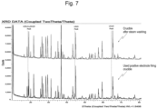
- FIG. 7 shows XRD (X-ray diffraction) graphs before and after the steam injection step (S20), and
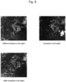
- FIG. 8 is comparative evaluation images of crucible washing after immersion in hot water.
- the lithium concentration step (S40) was performed on 500 ml of an aqueous solution containing lithium separated and recovered through the solid-liquid separation step (S30) performed on the slurry recovered through steam washing in the steam injection step (S20).
- the aqueous solution was evaporated and concentrated to about 41% by volume by being heated to 80°C under a reduced pressure condition of 76 Torr.
- 295 ml of lithium liquid was recovered, and 175 ml of condensate (separated liquid) was recovered through gas-liquid separation of the vapor generated during the concentration process, from which it is estimated that about 30 ml of water vaporized and released.
- the condensate and concentrated lithium liquid phase recovered through the gas-liquid separation were analyzed for main compositions and impurity components by using ICP-OES equipment. The data obtained through the analysis are shown in Table 6 of FIG.14 below.
- the aqueous solution containing lithium was concentrated depending on the evaporation rate.
- the condensate recovered through gas-liquid separation not to contain lithium can be reused as a steam injection supply liquid phase by being recirculated to the steam injection step (S20) via the steam supply step (S50) .
- the concentrated liquid phase is concentrated into a high-concentration lithium liquid phase by circulating through the processes until the target concentration is reached.
- the peaks of the main elements (Ni, Co) of a waste positive electrode material were confirmed for used crucibles, and since some of the lithium and most of the waste positive electrode material were recovered through steam washing, the peaks of the crucible components excluding these were confirmed.
- a system for recovering valuable metals from crucibles used in in the production of a positive electrode active material provides a series of automated systems capable of continuously recovering valuable metals including nickel, cobalt, and lithium efficiently while eliminating the use of acid solutions in the prior art.
- the system of the present disclosure injects medium-pressure steam and high-pressure steam to the side surfaces and bottom surfaces of crucibles where lithium, nickel, cobalt, and the like are present to be spread and penetrated into the surfaces and porous structures, thereby achieving an effect of maximizing the recovery efficiencies of valuable material without fully crushing and pulverizing crucibles as in the prior art.
- the present disclosure has an effect of significantly improving process and energy efficiency by collecting steam generated in the lithium concentration step and reusing the steam in the steam injection step.
- pulverization of lithium recovery process using high-pressure steam can significantly reduce the dust generated during the subsequent powder forming processes such as crushing and pulverization of the crucibles. Therefore, the present disclosure is expected to have great industrial applicability since there are various advantages such as a secondary load reduction effect on environmental facilities.
Landscapes
- Engineering & Computer Science (AREA)
- Chemical & Material Sciences (AREA)
- Materials Engineering (AREA)
- Organic Chemistry (AREA)
- Mechanical Engineering (AREA)
- Manufacturing & Machinery (AREA)
- Environmental & Geological Engineering (AREA)
- Metallurgy (AREA)
- Life Sciences & Earth Sciences (AREA)
- General Life Sciences & Earth Sciences (AREA)
- Geology (AREA)
- Geochemistry & Mineralogy (AREA)
- Chemical Kinetics & Catalysis (AREA)
- General Engineering & Computer Science (AREA)
- General Chemical & Material Sciences (AREA)
- Electrochemistry (AREA)
- Hydrology & Water Resources (AREA)
- Water Supply & Treatment (AREA)
- Physics & Mathematics (AREA)
- Thermal Sciences (AREA)
- Inorganic Chemistry (AREA)
- Manufacture And Refinement Of Metals (AREA)
Abstract
The present disclosure relates to a system for recovering valuable materials from a crucible used in the production of a positive electrode active material. The system includes: a crucible input unit (100) provided such that used positive electrode firing crucibles containing positive electrode material residue and lithium are placed thereon in a state in which openings of the crucible face downward, and are put into the system; a steam injection unit (200) defining a chamber and configured to sequentially move the crucibles put into the chamber and to inject high-pressure to inside and outside of the crucibles to separately collect slurry; a solid-liquid separation unit (300) configured to separate the slurry into solid and liquid, to discharge waste positive electrode material residue, and to separately collect a low-concentration lithium liquid phase; a lithium concentration unit (400) configured to recover a high-concentration lithium liquid phase concentrated to a target concentration through heating reaction of the low-concentration lithium liquid phase and to separately discharge steam; and a steam supply unit (500) configured to collect and reheat the discharged steam to a target temperature, and to supply high-pressure steam to the steam injection unit (200). As a result, an automated system that efficiently continuously recovers valuable metals by using and reusing high-pressure steam while eliminating the use of acidic solutions as in the prior art is provided.
Description
- This application is based on and claims priority to
Korean Patent Application No. 10-2023-0026708, filed on February 28, 2023 - The present disclosure relates to a system for recovering valuable materials from a crucible used in the production of a positive electrode active material. More specifically, the present disclosure relates to a series of automated systems for recovering valuable metals of a waste positive electrode material such as nickel and cobalt, and lithium from a firing crucible used in the production of a positive electrode, wherein valuable materials are efficiently and continuously recovered by using and reusing high-pressure steam while excluding the use of acidic solutions as in the prior art.
- Generally, lithium ion batteries generate electricity depending on the electrical flow of lithium ions moving through an electrolyte between a positive electrode and a negative electrode. A battery cell, the smallest unit of a secondary battery, includes a positive electrode material, a negative electrode material, an electrolyte, and a separator in a container. As the positive electrode material of the secondary battery, a positive electrode active material such as nickel, cobalt, manganese, or aluminum is used, and as the negative electrode material, a negative electrode active material such as graphite or carbon is used. The electrolyte contains a lithium salt made of lithium, phosphoric acid, and fluorine, and an organic solvent.
- High-nickel-based positive electrode materials such as nickel cobalt manganese (NCM) or nickel cobalt aluminum (NCA) is mainly used as a core material in medium-to-large batteries used in electric vehicles or energy storage systems. NCM and NCA are generally manufactured through a firing reaction by mixing lithium hydroxide or lithium carbonate with a high nickel-based precursor.
- For example,
Korean Patent No. 10-1069484 - Meanwhile, with the recent increase in the use of secondary batteries, interest in technologies related to the recycling of valuable metals such as lithium, nickel, manganese, and cobalt is increasing, and technologies for recovering valuable metals from lithium ion batteries, which are discarded after use, have been mainly developed and known.
- However, high-nickel-based positive electrode materials, which are used as a core material for medium-to-large batteries used in electric vehicles or energy storage systems, are produced through a high-temperature firing reaction in a crucible. Even though residues containing valuable metals of a positive electrode material such as nickel and cobalt and lithium are also generated on the surface of a crucible, most of the residues are discarded due to the lack of technology for recycling the residues.
-
- (Patent Document 1)
Korean Patent No. 10-1069484 (September 30, 2011 - (Patent Document 2)
Korean Patent No. 10-2191858 (December 16, 2020 - (Patent Document 3)
Korean Patent No. 10-1440241 (September 12, 2014 - (Patent Document 4)
Korean Patent No. 10-0434548 (September 18, 2004 - As described above, interest in technologies related to the recycling of valuable metals such as nickel, cobalt, and lithium is increasing due to the expansion of the electric vehicle market and the increased use of energy storage systems. Currently, most technologies are used to selectively recover valuable metals contained in lithium-ion batteries that are discarded after use through processes such as discharging and pulverizing.
- However, high-nickel-based positive electrode materials, which are used as core materials in medium-to-large-sized batteries, are produced by mixing lithium hydroxide or lithium carbonate with a high-nickel-based precursor and performing a high-temperature firing reaction in a crucible. In the case of lithium hydroxide, Li-Al-O (LiAlO2) is formed through a reaction with a crucible material during high-temperature firing, and during the repeated firing processes, the lithium hydroxide component penetrates into and diffuses from the surface of the crucible to the inside, creating a Li-Al-O structure inside.
- In addition, since LiAlO2, which is formed by the erosion reaction of a lithium compound on the surface of the crucible, causes cracks on the surface of the crucible, which reduces the recovery efficiency after producing a positive electrode material, periodic replacement of the crucible is necessary. Thus, despite the fact that used crucibles contain less than 1 wt% of lithium and positive electrode material residues, most of the used crucibles are discarded due to the lack of recycling technology.
- In addition, heavy metals such as nickel and cobalt, which are major components of positive electrode materials partially contained in used crucibles, cause serious environmental problems if disposed without being treated as designated waste. Therefore, simple disposal is not desirable, not only because it increases the environmental load, but also from the perspective of stability of supply and demand for major mineral resources.
- Meanwhile, a method of recovering valuable metals by powdering some of used crucibles through crushing and pulverizing processes and then performing a dissolution process of treating the powder with an acidic solvent. However, this method also has problems in that it is expected that about 99% of waste, excluding valuable materials, will be generated, and since the process of powdering the used crucible also requires a lot of energy costs and generates a large amount of dust, it is difficult to expect effectiveness in terms of recovery rate and efficiency.
- Accordingly, the present disclosure was made to solve the problems of the prior arts described above and provides a system that includes: a
crucible input unit 100 provided such that used positive electrode firing crucibles containing positive electrode material residue and lithium are placed thereon in a state in which openings of the crucible face downward, and are put into the system; asteam injection unit 200 defining a chamber and configured to sequentially move the crucibles put into the chamber and to inject high-pressure to inside and outside of the crucibles to separately collect slurry; a solid-liquid separation unit 300 configured to separate the slurry into solid and liquid, to discharge waste positive electrode material residue, and to separately collect a low-concentration lithium liquid phase; alithium concentration unit 400 configured to recover a high-concentration lithium liquid phase concentrated to a target concentration through heating reaction of the low-concentration lithium liquid phase and to separately discharge steam; and asteam supply unit 500 configured to collect and reheat the discharged steam to a target temperature, and to supply high-pressure steam to thesteam injection unit 200. As a result, it is possible to provide an automated system that continuously recovers valuable metals of a positive electrode material and lithium more efficiently by using and reusing high-pressure steam while excluding the use of acidic solutions as in the prior art. - The present disclosure provides a series of automated systems for recovering valuable metals of a waste positive electrode material such as nickel and cobalt, and lithium from a crucible used in a firing process for production of a positive electrode by using steam, wherein the valuable materials are efficiently and continuously recovered while excluding the use of acidic solutions as in the prior art.
- In particular, the system of the present disclosure injects medium-pressure steam and high-pressure steam to the side surfaces and bottom surfaces of crucibles where nickel, cobalt, and the like are present to be spread and penetrated into the surfaces and porous structures, thereby achieving an effect of maximizing the recovery efficiencies of valuable material without fully crushing and pulverizing crucibles as in the prior art.
- In addition, the present disclosure has an effect of significantly improving process and energy efficiency by collecting steam generated in the lithium concentration step and reusing the steam in the steam injection step.
- According to the present disclosure, the moisture remaining in the crucibles after being subjected to the valuable metal recovery process using steam can significantly reduce the dust generated during the subsequent powder forming processes such as crushing and pulverization of the crucibles. Therefore, there is an advantage in that a secondary load reduction effect on environmental facilities can be achieved.
- The above and other aspects, features and advantages of the present disclosure will be more apparent from the following detailed description taken in conjunction with the accompanying drawings, in which:
-
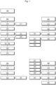
FIG. 1 is a schematic block diagram of a system for recovering valuable metals from a crucible used in the production of a positive electrode active material according to an embodiment of the present disclosure; -
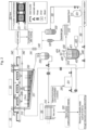
FIG. 2 is a schematic view of a system for recovering valuable metals from a crucible used in the production of a positive electrode active material according to an embodiment of the present disclosure; -
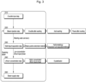
FIG. 3 is a schematic flowchart of a lithium recovery method by a system for recovering valuable metals from a crucible used in the production of a positive electrode active material according to an embodiment of the present disclosure; -
FIG. 4 is a schematic flowchart of a valuable metal recovery method by a system for recovering valuable metals from a crucible used in the production of a positive electrode active material according to an embodiment of the present disclosure; -
FIG. 5 is a view illustrating images of resultant objects obtained by executing steps from a crucible input step to a solid-liquid separation step according to an embodiment of the present disclosure; -
FIG. 6 is a graph showing the weights of valuable metals recovered from a crucible; -
FIG. 7 is a view illustrating X-ray diffraction (XRD) graphs before and after a steam injection step according to an embodiment of the present disclosure; -
FIG. 8 is a view illustrating comparative evaluation images of crucible washing after immersion in hot water. -
FIG. 9 is a table 1 to show a positive electrode active material to be recovered; -
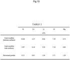
FIG. 10 is a table 2 to show the main composition and impurities of each sample ofembodiment 1; -
FIG. 11 is a table 3 to show the used positive electrode firing crucibles utilized in the measurement of the above implementation data ofembodiment 1; -
FIG. 12 is a table 4 to show data analyzed obtained for main compositions and impurity components ofembodiment 2; -
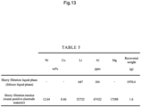
FIG. 13 is a table 5 to show the component analysis data ofembodiment 2; -
FIG. 14 is a table 6 to show the data obtained through the analysis ofembodiment 3; -
FIG. 15 is a table 7 to show data ofembodiment 4; and -
FIG. 16 is a table 8 to show other data ofembodiment 4. - Hereinafter, the configuration and operation of a system for recovering valuable metals from a crucible used in the production of a positive electrode active material according to an embodiment of the present disclosure will be described in detail with reference to the accompanying drawings.
- The system for recovering valuable metals from a crucible used in the production of a positive electrode active material to which the technology of the present disclosure is applied relates to a series of automated systems that are capable of recovering valuable metals including nickel, cobalt, and lithium from the used crucible, wherein valuable metals can be more efficiently and continuously recovered through the using and reusing of high-pressure steam while excluding the use of acidic solutions in the prior art.
- For this purpose, the system for recovering valuable metals from a crucible used in the production of a positive electrode active material according to the present disclosure generally includes a
crucible input unit 100, asteam injection unit 200, a solid-liquid separation unit 300, alithium concentration unit 400, and asteam supply unit 500, and a specific configuration of the system will be described below. - The
crucible input unit 100 is provided such that a used positive electrode firing crucible containing positive electrode material residue and lithium is placed in a state in which the opening of the crucible faces downward and is put into the system. - The used crucible put into the
crucible input unit 100 includes not only LiAlO2 generated by the erosion reaction of a lithium compound, but also some residual positive electrode material after the firing reaction. - As shown in Table 1 of
FIG.9 below, valuable metals to be recovered, such as nickel, cobalt, and lithium, are most abundant on the bottom surface of the crucible, which is the main reaction area, and are also present on the side surface (side wall) of the crucible due to LiAlO2 formed through the erosion reaction. - However, far from the reaction surface, there are portions of the crucible where no erosion reaction has not occurred. Therefore, when the crucibles are fully crushed and pulverized as in the prior art, the concentration of valuable metals to be recovered, such as nickel, cobalt, and lithium, is reduced due to the mixing of Al-Si-Mg oxide, which is the main component of the crucible, thereby reducing recovery efficiency.
- Therefore, when high-pressure steam is used for the effective area in a non-destructive manner that does not crush or pulverize the entire used crucible, selective separation and recovery is possible, thereby improving recovery efficiency.
- The
crucible input unit 100 of the present disclosure is configured to put the used crucible into the system in its original form without crushing or pulverizing the crucible so that the crucible is supplied to thesteam injection unit 200, which will be described later. - The
steam injection unit 200 includes a chamber and is configured to sequentially move the crucible put into the chamber and inject high-pressure steam to the inside and outside of the crucible to collect the slurry separately, wherein thesteam injection unit 200 is configured to inject medium- and high-pressure steam to the side surface and bottom surface of the used crucible, which are the areas where valuable metals are most abundantly distributed, to recover valuable metals including nickel, cobalt, and lithium. - The
steam injection unit 200 is configured to effectively collect slurry containing valuable metals by high-pressure steam injection and supply the slurry to a subsequent unit. - Therefore, the steam injection unit is configured to solve the problems of the system in the prior art in which, by recovering valuable metals through a leaching process using a solvent such as sulfuric acid (H2SO4) after crushing and pulverizing the crucible itself into powder, it is necessary to process, excluding about 1 wt% of valuable metals to be recovered, about 99% of the waste valuable metals, resulting in inefficiency and high energy costs.
- The
steam injection unit 200 includes acrucible movement module 210 and a firststeam injection module 220 inside a sealed chamber space, wherein thecrucible movement module 210 moves in one direction inside the chamber, and above thecrucible movement module 210, spacing guides 211, which are seated on the outer periphery of the opening of the crucible, are arranged at regular intervals. - The
crucible movement module 210 uses, for example, a chain conveyor, a roll type conveyor, or a belt type conveyor to seat the crucible with the opening facing downward, and is configured to move in the state of being seated on the outer periphery excluding the opening of the crucible such that high-pressure steam by the firststeam injection module 220, which will be described later, can be applied to the inside of the opening of the crucible. - The moving speed of the
crucible moving module 210 is set depending on a time period of steam injection for the crucible in the range of 10 minutes to 24 hours. - The spacing guides 211 provided in the
crucible movement module 210 are arranged to move a plurality of crucibles put into the system to move at the same spacing as the arrangement spacing of the firststeam injection modules 220, which will be described later, and adrop prevention member 270 is provided under thecrucible movement module 210. - The
drop prevention member 270 of thecrucible movement module 210 is configured to prevent damaged things from falling to the firststeam injection modules 220 and theslurry collection module 230, which will be described later, when an unexpected crack damage occurs in the used crucible due to the high-pressure steam by being provided in a mesh form under thecrucible movement module 210. - The first
steam injection modules 220 have nozzles arranged at regular intervals vertically below thecrucible movement module 210 and are provided to inject high-pressure steam supplied from thesteam supply unit 500 into the crucibles. - The first
steam injection modules 220 are arranged at intervals corresponding to the positions of a plurality of crucibles that are moved at regular intervals with the openings facing downward by thecrucible movement module 210 and are configured to inject high-pressure steam to respective crucibles. The firststeam injection modules 220 are configured to receive steam by being connected to afirst steam line 542 from asteam supply unit 500, which will be described in detail below. - The first
steam injection modules 220, each of which is provided with a single-type nozzle or multiple-type nozzles, are arranged at regular intervals. - For example, as the distance between the nozzles of the first
steam injection modules 220 and the crucibles increases, the contact temperature of the crucibles with steam decreases. - To correct this, when the steam pressure injected from the nozzles is set strong and continues at a level that causes the crucibles to shake, the surfaces of the crucibles may be severely chipped, which may lead to cracks, and when the raw materials of the crucibles are mixed into the slurry due to cracks, the recovery rate of valuable metals may decrease. Therefore, it is desirable to organically consider the distance between the nozzles and the surfaces of the crucibles, the weight of the crucibles, and the injection form and pressure of the steam nozzles.
- A single-type nozzle is provided at a position corresponding to the deep portion of each crucible to inject high-pressure steam over an entire radial area, and multiple-type nozzles are provided at multiple positions corresponding to the shapes of a crucible to inject high-pressure steam to respective areas.
- The single-type nozzle or the multiple-type nozzles are installed such that the injection direction of high-pressure steam can be fixed or rotated to minimize a non-cleaned area (dead zone) on the bottom surface and side surface of the crucible.
- The temperature of the high-pressure steam injected to the crucibles by the first
steam injection modules 220 is set to be in the range of 100 to 230°C. - The first
steam injection modules 220 are configured to inject steam at a temperature in the above-mentioned range, preferably around 100 to 150°C, to maximize the power of washing the slurry containing valuable metals from the surfaces of the crucibles having a porous structure, thereby effectively securing the washing power while minimizing unnecessary heat consumption. Since the steam injected by the firststeam injection modules 220 is greatly affected by temperature,primary shielding modules secondary shielding modules steam injection unit 200. - The
primary shielding modules secondary shielding modules - The
steam injection unit 200 further includes secondsteam injection modules 260, wherein the secondsteam injection modules 260 have nozzles arranged at regular intervals above thecrucible movement module 210 and are configured to inject high-pressure steam supplied from thesteam supply unit 500 to the outside of the crucibles and thecrucible movement module 210. - The second
steam injection modules 260 are disposed above the crucibles moved by thecrucible movement module 210 and are configured to inject high-pressure steam to the outers surfaces of the crucibles, thecrucible movement module 210, and thedrop prevention member 270. - The second
steam injection modules 260 are provided to recover the waste positive electrode material remaining on the outside of the crucibles and to clean the gap between thecrucible movement module 210 and thedrop prevention member 270, thereby preventing the recovery rate and efficiency rate from being reduced due to adhesion of foreign substances or the like in the system. - In addition, the second
steam injection modules 260 are configured to receive steam by being connected to asecond steam line 543 from thesteam supply unit 500, which will be described in detail below. - The
steam injection unit 200 includes aslurry collection module 230 located below thecrucible movement module 210. - The
slurry collection module 230 is provided with a settling tank that forms aslope 231 in one direction under the firststeam injection modules 220 to collect the slurry, which contains valuable metals and steam washing liquid falling from the crucibles, with a slurrystirring collection tank 232. - The
slurry collection module 230 is configured to collect the slurry, which falls in the state of containing valuable materials, along with the steam injected by the firststeam injection module 220 and the secondsteam injection module 260, with theslurry stirring tank 232 disposed at the lower end of theslope 231. - The
slurry stirring tank 232 is equipped with, for example, one or more turbine-type or paddle-type impellers, and is configured to store the recovered steam washing liquid and slurry as a homogeneous slurry in a stirred state and to supply the slurry to the solid-liquid separation unit 300, which will be described later, by controlling a valve when the slurry reaches a predetermined level. - The crucibles from which valuable metals have been recovered while passing through the
steam injection unit 200 can be discharged to the outside of the chamber and recovered in the form of powder through crushing and pulverizing processes. At this time, moisture can be evaporated quickly when the crucibles are moved to the outside due to steam heat, and some remaining moisture may have the secondary effect of reducing dust scattering during crushing and pulverizing operations. - The solid-
liquid separation unit 300 is configured to perform solid-liquid separation, discharge waste positive electrode material residues containing some crucible components and lithium, and separately collect a low-concentration lithium liquid phase, and to introduce the slurry into theslurry collection module 230 by being connected to theslurry stirring tank 232 of theslurry collection module 230, wherein the solid-liquid separation unit 300 includes afiltration module 310, aresidue discharge module 320, and aliquid collection module 330. - The
filtration module 310 is configured to receive the slurry collected from thesteam injection unit 200 and to filter the slurry by using a filter press, and wherein thefiltration module 310 is configured to separate the slurry into solid waste positive electrode material residue and a low-concentration lithium liquid phase by being provided as the filter press. - The
residue discharge module 320 is configured to separately discharge the filtered waste positive electrode material residue and use the same for the recovery of valuable metals. Since the filtered residue discharged through theresidue discharge module 320 may contain metals such as Al and Mg in addition to Ni and Co, which are the main components of the waste positive electrode material, the filtered residue may be separated and purified through recovery methods such as solvent extraction or precipitation to enable additional recovery. - The
liquid collection module 330 is configured to collect the filtered low-concentration lithium liquid phase in a filteredliquid phase tank 331 and to supply the lithium liquid phase to thelithium concentration unit 400 or to circulate the lithium liquid phase to thesteam injection unit 200. - The low-concentration lithium solution discharged through the
liquid collection module 330 is temporarily stored in the filteredliquid phase tank 331 and then supplied to theliquid supply module 410 of thelithium concentration unit 400, which will be described later. In addition, a portion of the liquid stored in the filtratedliquid phase tank 331 may be used to prevent the waste positive electrode materials from adhering to the inner wall and from forming scale sticking phenomenon and scale formation caused by waste anode materials or the like by being put into theslurry stirring tank 232 when necessary. - The
lithium concentration unit 400 is configured to recover the high-concentration lithium liquid concentrated to the target concentration through heating and reaction of the low-concentration lithium liquid and to separately discharge steam. Thelithium concentration unit 400 is configured such that the low-concentration lithium liquid phase stored in thefiltration liquid tank 331 of the solid-liquid separation unit 300 is introduced into thelithium concentration unit 400 to be concentrated into the high-concentration lithium liquid phase, wherein thelithium concentration unit 400 includes aliquid supply module 410 and aconcentration reaction module 420. - The
liquid supply module 410 is configured to supply the low-concentration lithium liquid phase collected in the solid-liquid separation unit 300 to the upper portion of theconcentration reaction module 420, which will be described later, wherein theconcentration reaction module 420 is configured to concentrate the supplied low-concentration lithium liquid phase into the high-concentration lithium liquid phase through evacuation and heating. - The
concentration reaction module 420 is configured to obtain a highly concentrated lithium liquid phase by evaporating and concentrating the low concentration lithium liquid phase through heating, and includes areaction tank 421, aheat supply unit 423, and awashing injection unit 424. - The
reaction tank 421 includes aninsulation portion 422 jacketed outside the reaction tank and a stirrer installed inside the rection tank, wherein thereaction tank 421 is provided in the form of a jacketed reactor and is insulated from the outside to minimize the loss of heat supplied from theheat supply unit 423, which will be described later. - The
reaction tank 421 is configured to reduce the pressure of the internal liquid phase with a vacuum pump and rotate the internal liquid phase with a stirrer. The stirrer may to be equipped with, for example, one or more turbine-type or paddle-type impellers. - The
reaction tank 421 is equipped with a predetermined pressure gauge P, and when the internal pressure is excessively different from the external pressure, the pressure difference is relieved through a vent or the system is stopped to prevent safety accidents. - The
heat supply unit 423 is provided to supply heat to thereaction tank 421 to heat thereaction tank 421. - The
washing injection unit 424 is configured to selectively inject distilled water from the top of thereaction tank 421, wherein thewashing injection unit 424 is provided with a plurality of nozzles that inject distilled water throughout the interior of thereaction tank 421, and wherein thewashing injection unit 424 is configured to compensate for the amount of moisture absorbed or lost in the crucibles as needed and to clean salts or foreign substances attached to the inner wall of thereaction tank 421 or asteam screen 431, which will be described later. - The
concentration reaction module 420 includes a recoveryconcentration measuring unit 425, wherein the recoveryconcentration measuring unit 425 is configured to measure the lithium concentration in the high-concentration lithium liquid phase and to discharge the high-concentration lithium liquid phase to a concentratedlithium recovery module 440 when the lithium concentration reaches 8 to 10 weight% or more. - The
lithium concentration unit 400 basically performs a steam supply step by asteam supply unit 500, which will be described later, until the lithium concentration reaches the target value during the evaporation concentration process, wherein the recoveryconcentration measuring unit 425 has a sampling point in a lower portion of thereaction tank 421 to analyze the lithium concentration in the liquid phase and is configured to allow the concentratedlithium recovery module 440 to recover the high-concentration lithium liquid phase when the lithium concentration reaches a level equal to or higher than the target value. - The
steam discharge module 430 is configured to screen the steam generated in theconcentration reaction module 420 and discharge the steam to thesteam supply unit 500, wherein thesteam discharge module 430 is configured to discharge heated and generated under a reduced pressure in thereaction tank 421 to thesteam supply unit 500, which will be described later. - The heated steam may have a temperature lower than 100°C, and in order to prevent the formation of salt or scale during the supply of steam to the
steam supply unit 500, asteam screen 431 is mounted on the upper discharge path of thereaction tank 421 to discharge only pure steam. - The concentrated
lithium recovery module 440 is configured to recover the high-concentration lithium liquid concentrated in theconcentration reaction module 420, wherein the concentratedlithium recovery module 440 is configured to recover the high-concentration lithium liquid phase when it is determined that the high-concentration lithium liquid phase reaches the target concentration by theconcentration measuring unit 425 and discharged from thereaction tank 421. - The lithium in the liquid recovered by the concentrated
lithium recovery module 440 may exist in the form of an aqueous solution of lithium compounds containing lithium hydroxide (Li(OH)), lithium carbonate (Li2CO3), and the like remaining in the crucibles during the positive electrode firing process and may be concentrated in the range of 8 to 10 wt%. - The
steam supply unit 500 is configured to collect discharged steam, to reheat the collected steam to a target temperature, and to supply the heated steam to thesteam injection unit 200 as high-pressure steam, wherein thesteam supply unit 500 is configured to recover the steam generated during the concentration process by thelithium concentration unit 400 through thesteam discharge module 430 and re-supply the steam to thesteam injection unit 200, and includes a gas-liquid separation module 510, asteam reheating module 520, asteam regeneration module 530, and asteam supply module 540. - The gas-
liquid separation module 510 is configured to collect the steam generated in thelithium concentration unit 400 and to separate the collected steam into separated gas and separated liquid, wherein in order to prevent the formation of scale by the collected steam, the gas-liquid separation module 510 is configured to separate the collected steam into the separated gas and the separated liquid and to supply the separated gas and the separated liquid to asteam reheating module 520 and asteam regeneration module 530, respectively, which will be described later. - The
steam reheating module 520 is connected to the gas-liquid separation module 510 and is configured to reheat the separated gas to a target pressure and temperature, wherein thesteam reheating module 520 reheats the separated gas to the target pressure and temperature to form saturated steam or super-heated steam. - The steam that has passed through the
steam reheating module 520 contains latent heat and is at a higher pressure than the steam discharged from thelithium concentration unit 400, thereby maximizing transportation efficiency with a small specific volume, wherein thesteam reheating module 520 is configured to reheat the separated gas indirectly or directly by applying, for example, a boiler or a heat exchanger. - The
steam regeneration module 530 is configured to receive the separated liquid from a separatedliquid phase tank 531 connected to the gas-liquid separation module 510 and to generate steam at the target pressure and temperature, wherein thesteam regeneration module 530 is configured to temporarily store the separated liquid in the separatedliquid tank 531 and to control the supply of the stored liquid by a valve to regenerate steam. - The steam regenerated by the
steam regeneration module 530 meets the steam that has passed through thesteam reheating module 520 through a steam flow pipe (not denoted by a reference numeral) and is supplied to thesteam supply module 540, which will be described later. Thesteam supply module 540 is configured to filter the steam formed in thesteam reheating module 520 and thesteam regeneration module 530 and supply the filtered steam to thesteam injection unit 200. - The
steam supply module 540 includes asteam filter 541, afirst steam line 542, and asecond steam line 543. - The
steam filter 541 is installed on a steam flow line connected to thesteam reheating module 520 and thesteam regeneration module 530, and thesteam filter 541 filters the steam formed by thesteam reheating module 520 and thesteam regeneration module 530 such that the steam can be reused as crucible washing steam in thesteam injection unit 200. - The
first steam line 542 is configured to supply steam to be injected into the openings of crucibles by being connected to the firststeam injection module 220 of thesteam injection unit 200 on the rear side of thesteam filter 541. - The
second steam line 543 is configured to supply steam to be injected to the external upper surfaces of crucibles by being connected to the secondsteam injection module 260 of thesteam injection unit 200 on the rear side of thesteam filter 541. - Hereinafter, a method for recovering valuable metals by a system for recovering valuable metals from crucibles used in the production of a positive electrode active material, to which the technique of the present configured as described above is applied, will be described.
- The following description will be made by taking embodiments of the present disclosure as examples, and the present disclosure is not limited to the following examples.
- A method for recovering valuable metals by using high-pressure steam from a crucible used for the production of a positive electrode active material according to the present disclosure generally includes a crucible input step (S10), a steam injection step (S20), a solid-liquid separation step (S30), a lithium concentration step (S40), and a steam supply step (S50).
- In the crucible input step (S10), a plurality of used anode firing crucibles are put into a system at regular intervals in their original states in a state where openings thereof face downward.
- In detail, the steam injection step (S20) includes primary and secondary shielding steps (S21), a crucible movement step (S22), first and second steam injection steps (S23), slurry discharge step (S24), and a crucible discharge step (S25).
- In the primary and secondary shielding steps (S21), when the crucibles are put into the
primary shielding modules primary shielding modules secondary shielding modules crucible movement module 210. - In the crucible movement step (S22), the crucibles put into the chamber are moved in one direction while maintaining a predetermined distance therebetween on the
crucible movement module 210 by the spacing guides 211. - In the first and second steam injection steps (S23), the first
steam injection modules 220 inject high-pressure steam radially or closely to each area inside the openings of respective crucibles from the bottom sides of the moving crucibles. At the same time, the secondsteam injection modules 260 inject high-pressure steam to the outer upper portions of the respective crucibles from the top sides of the crucibles to wash thecrucible movement module 210 and thedrop prevention member 270. - In the slurry discharge step (S24), washing water (steam) slurry containing valuable materials that fall to the
slurry collection module 230 under the chamber through the first and second steam injection steps (S23) are discharged in one direction along theslope 231 and collected in theslurry stirring tank 232. - In the crucible discharge step (S25), the crucibles that have been subjected to the steam injection step (S20) are discharged to the outlet of the chamber. On the outlet side of the chamber, the crucibles that have been subjected to the steam injection step (S20) are sequentially discharged. When the crucibles are discharged outside the
secondary shielding modules secondary shielding modules primary shielding modules - The crucibles discharged in the crucible discharge step (S25) can be recovered in a powder form through later pickling, crushing, and pulverizing processes, and by being subjected to the first and second steam injection steps (S23), the secondary effect of reducing the scattering of dust during crushing and pulverizing operations can be obtained due to the moisture remaining in the crucibles.
- In detail, the solid-liquid separation step (S30) includes a slurry-solid-liquid separation step (S31), a residue discharge step (S32), and a liquid phase collection step (S33).
- In the slurry solid-liquid separation step (S31), the slurry collected and homogeneously stirred in the
slurry stirring tank 232 is introduced into and filtered by thefiltration module 310 and is separated into solid waste positive electrode material residue and low-concentration lithium liquid phase. - In the residue discharge step (S32), the
residue discharge module 320 separately discharges the separated waste positive electrode material residue. The discharged waste positive electrode material can be used in hydrometallurgical processes such as melting and separation refining to recover additional valuable metals. - In the liquid collection step (S33), the
liquid collection module 330 collects the separated low-concentration lithium liquid phase in thefiltration liquid tank 331. The low-concentration lithium liquid phase collected in thefiltration liquid tank 331 is supplied to thelithium concentration unit 400, or some of the low-concentration lithium liquid phase is circulated to thesteam injection unit 200 and is used to prevent scale formation inside theslurry stirring tank 232. - The lithium concentration step (S40) includes, in detail, a liquid supply step (S41), a concentration reaction step (S42), a steam discharge step (S43), and a concentrated lithium recovery step (S44).
- In the liquid supply step (S41), the
liquid supply module 410 causes the low-concentration lithium liquid phase stored in thefiltration liquid tank 331 to flow into thereaction tank 421 of theconcentration reaction module 420. - In the concentration reaction step (S42), the
concentration reaction module 420 heats the low-concentration lithium liquid phase supplied to thereaction tank 421 defining thejacketed insulation portion 422 by theheat supply unit 423 while stirring the low-concentration lithium liquid phase with the stirrer to evaporate and concentrate the low-concentration lithium liquid phase into a high-concentration lithium phase. - In the concentration reaction step (S42), if necessary, distilled water is injected throughout the
reaction tank 421 by thewashing injection unit 424 to compensate for the amount of moisture absorbed in the crucibles and to wash the inner wall of thereaction tank 421 and thesteam screen 431. - In the steam discharge step (S43), the
steam discharge module 430 screens the steam generated during the concentration reaction step (S42) through thesteam screen 431 and discharges it to thesteam supply unit 500. - In the concentrated lithium recovery step (S44), the lithium concentration is measured by the recovery
concentration measuring unit 425 during the concentration reaction step (S42), and the high-concentration lithium liquid phase concentrated in the range of 8 to 10 wt% is recovered by the concentratedlithium recovery module 440. - The high-concentration lithium liquid recovered through the concentrated lithium recovery step (S44) is recovered later as lithium through a crystallization process.
- The steam supply step (S50) includes, in detail, a steam gas-liquid separation step (S51), a separated gas steam reheating step (S52), a separated liquid steam regeneration step (S53), and first and second steam line supply steps (S54) .
- In the steam-liquid separation step (S51), the gas-
liquid separation module 510 collects the steam discharged in the steam discharge step (S43) and separates the steam into separated gas and separated liquid, and supplies the separated gas and the separated liquid to thesteam reheating module 520 and the steam generation module, respectively. - In the separated gas steam reheating step (S52), the
steam reheating module 520 reheats the separated gas to a target pressure and temperature to form saturated steam or superheated steam. - In the separated liquid steam regeneration step (S53), the
steam regeneration module 530 temporarily stores the separated liquid in the separatedliquid tank 531 and controls the supply of the stored liquid by a valve to regenerate steam at a target pressure and temperature. - In the first and second steam line supply steps (S54), the
steam supply module 540 filters the steam formed in the separated gas steam reheating step (S52) and the separated liquid steam regeneration step (S53) through thesteam filter 541 and supplies the steam to the firststeam injection module 220 and the secondsteam injection module 260 through thefirst steam line 542 and thesecond steam line 543, respectively. - Hereinafter, examples in which the present disclosure was implemented as described above were prepared, and the effects thereof were carefully examined through experiments as described below.
- In order to confirm the composition of used positive electrode firing crucibles, samples were collected by grinding the side and bottom portions of the crucibles by 5 mm.
- In order to confirm the main composition and impurities, 1g of each sample was dissolved in 10 ml of aqua regia, and data were measured by using high-frequency inductively coupled plasma (ICP-OES) equipment, as shown in Table 2 of
FIG.10 below. - The used crucibles contained not only LiAlO2 generated from the erosion reaction of a lithium compound, but also some residual positive electrode materials after firing reaction. As the distance from the surfaces of the crucibles increased, there were portions where no erosion reaction occurred. During crushing and pulverization, the lithium concentrations decreased to 0.5 to 1.5 wt%, and the waste positive electrode metals (Ni, Co, and the like) remaining on the surfaces also decreased so that Ni decreased to about 0.13wt% and Co decreased to about 0.01wt%.
- In the prior art, there is a method of recovering valuable metals through a leaching process using a dissolving agent such as sulfuric acid after crushing a used crucible itself. However, it is necessary to treat 99% of waste containing Ni and Co, which are heavy metals harmful to the environment, and since impurities such as Al and Mg are dissolved together, the recovery efficiency is significantly low.
- Therefore, the present disclosure provides a valuable metal recovery system using high-pressure steam that is different from the prior art.
- The used positive electrode firing crucibles utilized in the measurement of the above implementation data, had the specifications as shown in Table 3 of
FIG.11 below. The average values of the used crucibles utilized in this example were confirmed by measuring each specification for the crucible that were discharged through about 21 firing cycles. - A steam injection step (S20) was performed to recover the remaining waste positive electrode material and lithium on the inner bottom surfaces and side surfaces of used crucibles, which had an actual weight of 7.99 kg.
- The steam pressure was set to about 15 bar with steam generates rated 10 to 30 bars, and the steam temperatures measured on the surfaces of the crucibles was confirmed to be in the range of 100 to 150°C. Slurry containing waste positive electrode material was recovered by injecting steam at a rate of 40.8 cm2/min over the entire internal areas by using a single injection nozzle, and the temperatures of the recovered slurry were confirmed to be 45 to 50°C.
- In the solid-liquid separation step (S30), 2.94 kg of filtrated liquid phase samples and 38.5 g of dried filtration residue samples were obtained through filtration under a reduced pressure, and data analyzed obtained for main compositions and impurity components by using ICP-OES equipment are shown in Table 4 of
FIG.12 below.FIG. 5 illustrates the images of process results obtained by performing steps from the crucible input step to the solid-liquid separation step (S10 to S30), andFIG. 6 is a graph showing the weights of valuable metals recovered from a crucible. - In the filtered liquid phase, an aqueous solution containing ionized Li was obtained, in the slurry filtration residue, most of nickel and cobalt, which are the main components of the waste positive electrode material were recovered at 95% and 93% or more, respectively.
- In addition, not only lithium but also aluminum and magnesium, which are main components of the crucible, were observed, and are presumed to have been partially separated from the used crucible in the steam injection step (S20).
- In order to compare the washing effect by high-pressure steam according to the present disclosure and the washing effect by hot water immersion, a comparation was performed by preparing standard samples of 1.32 kg (about 16.5% of the total weight) of the bottom surfaces of the crucibles were prepared and immersing the samples in 2L of hot water at 90°C for 1 hour.
- The component analysis data for filtered liquid obtained by filtering the recovered hydrothermal washing liquid under a reduced pressure are shown in Table 5 of
FIG.13 below. For reference,FIG. 7 shows XRD (X-ray diffraction) graphs before and after the steam injection step (S20), andFIG. 8 is comparative evaluation images of crucible washing after immersion in hot water. - Compared to the present disclosure, it can be seen that most of the waste positive electrode material is not recovered from filtration residue in slurry by hot water immersion.
- The lithium concentration step (S40) was performed on 500 ml of an aqueous solution containing lithium separated and recovered through the solid-liquid separation step (S30) performed on the slurry recovered through steam washing in the steam injection step (S20).
- The aqueous solution was evaporated and concentrated to about 41% by volume by being heated to 80°C under a reduced pressure condition of 76 Torr. In this process, 295 ml of lithium liquid was recovered, and 175 ml of condensate (separated liquid) was recovered through gas-liquid separation of the vapor generated during the concentration process, from which it is estimated that about 30 ml of water vaporized and released. The condensate and concentrated lithium liquid phase recovered through the gas-liquid separation were analyzed for main compositions and impurity components by using ICP-OES equipment. The data obtained through the analysis are shown in Table 6 of
FIG.14 below. - In the lithium concentration step (S40), the aqueous solution containing lithium was concentrated depending on the evaporation rate. The condensate recovered through gas-liquid separation not to contain lithium can be reused as a steam injection supply liquid phase by being recirculated to the steam injection step (S20) via the steam supply step (S50) . In addition, the concentrated liquid phase is concentrated into a high-concentration lithium liquid phase by circulating through the processes until the target concentration is reached.
- After the steam injection step (S20), in order to confirm the possibility of recovering additional lithium from used crucibles from which most of the waste positive electrode material and lithium were recovered, a standard sample of 0.99 kg was produced, and additional dissolution evaluation was conducted for 2 hours under conditions of 80°C and pH 1.0. Data obtained by analyzing main compositions and impurity components by using ICP-OES equipment are shown in Table 7 of
FIG.15 below. - Based on the Al, Mg, and Si compounds, which are the main components of the crucible, the peaks of the main elements (Ni, Co) of a waste positive electrode material were confirmed for used crucibles, and since some of the lithium and most of the waste positive electrode material were recovered through steam washing, the peaks of the crucible components excluding these were confirmed.
- Through the dissolution evaluation of the crucibles after the steam injection step (S20), it was confirmed that recovery of additional lithium was possible, but Al was dissolved at a similar rate. Therefore, when recovering lithium by using a solvent in the future, it is expected that the direction for removing impurities should be reviewed.
- Data obtained by analyzing main compositions and impurity components for dissolved crucibles by using ICP-OES equipment are shown in Table 8 of
FIG.16 below. As a result of the analysis, it was confirmed that some Li remains, but since the amount is a very small amount of about 0.6% of all of the crucibles, it is expected that no clear peak will be detected during XRD analysis. - As described above, a system for recovering valuable metals from crucibles used in in the production of a positive electrode active material according to the present disclosure provides a series of automated systems capable of continuously recovering valuable metals including nickel, cobalt, and lithium efficiently while eliminating the use of acid solutions in the prior art.
- In particular, the system of the present disclosure injects medium-pressure steam and high-pressure steam to the side surfaces and bottom surfaces of crucibles where lithium, nickel, cobalt, and the like are present to be spread and penetrated into the surfaces and porous structures, thereby achieving an effect of maximizing the recovery efficiencies of valuable material without fully crushing and pulverizing crucibles as in the prior art.
- In other words, compared to the prior art for the same period of time, when using the high-pressure steam of the present disclosure as a recovery method using hot water, it was possible to recover most of valuable metals in a waste positive electrode material in the form of residue, and the recovery efficiency for all the crucibles was also confirmed to be close to 90% for Ni and Co.
- In addition, the present disclosure has an effect of significantly improving process and energy efficiency by collecting steam generated in the lithium concentration step and reusing the steam in the steam injection step.
pulverization of lithium recovery process using high-pressure steam can significantly reduce the dust generated during the subsequent powder forming processes such as crushing and pulverization of the crucibles. Therefore, the present disclosure is expected to have great industrial applicability since there are various advantages such as a secondary load reduction effect on environmental facilities.
Claims (12)
- A system for recovering a valuable metal from a crucible used to produce a positive electrode active material, the system comprising:a crucible input unit (100) provided such that used positive electrode firing crucibles containing positive electrode material residue and lithium are placed thereon in a state in which openings of the crucible face downward, and are put into the system;a steam injection unit (200) defining a chamber and configured to sequentially move the crucibles put into the chamber and to inject high-pressure to inside and outside of the crucibles to separately collect slurry;a solid-liquid separation unit (300) configured to separate the slurry into solid and liquid, to discharge waste positive electrode material residue, and to separately collect a low-concentration lithium liquid phase;a lithium concentration unit (400) configured to recover a high-concentration lithium liquid phase concentrated to a target concentration through heating reaction of the low-concentration lithium liquid phase and to separately discharge steam; anda steam supply unit (500) configured to collect and reheat the discharged steam to a target temperature, and to supply high-pressure steam to the steam injection unit (200).
- The system of Claim 1, wherein the steam injection unit (200) comprises:a crucible movement module (210) configured to operate in one direction inside the chamber and having spacing guides (211) arranged to seat outer peripheries of the openings of the crucibles at regular intervals on a top of the crucible movement module;a first steam injection module (220) having nozzles arranged at regular intervals vertically below the crucible movement module (210), the first steam injection module being configured to supply the high-pressure steam from the steam supply unit (500) into the crucibles; anda slurry collection module (230) defining a slope (231) in one direction below the first steam injection module (220), the slurry collection module 230 configured to collect slurry falling from the crucibles into a slurry stirring tank (232) .
- The system of Claim 2, wherein the first steam injection module (220) comprises:one nozzle provided at a position corresponding to a deep portion of each crucible and configured to inject the high-pressure steam over an entire radial area, or multiple nozzles arranged at regular intervals to be provided at multiple positions corresponding to a shape of each crucible and configured to inject the high-pressure steam at respective portions, andwherein the single nozzle or the multiple nozzles are installed such that an injection direction of the high-pressure steam can be fixed or rotated.
- The system of Claim 2, wherein the high-pressure steam injected into the crucibles by the first steam injection module (220) has a temperature of 100 to 230°C.
- The system of Claim 1, wherein the steam injection unit 200 comprises primary shielding modules (241, 242) and secondary shielding modules (251, 252) are dually installed on inlet and outlet sides of the chamber, respectively, to shield the inside of the chamber when putting and discharging the crucibles into and from the chamber.
- The system of Claim 1, wherein the steam injection unit (200) comprises a second steam injection module having nozzles arranged at regular intervals above the crucible movement module (210) and configured to inject the high-pressure steam supplied from the steam supply unit (500) to the outside of the crucibles and the crucible movement module (210) .
- The system of Claim 1, wherein the solid-liquid separation unit (300) comprises:a filtration module (310) configured to receive slurry collected from the steam injection unit 200 and to filter the slurry with a filter press;a residue discharge module (320) configured to separately discharge filtered waste positive electrode material residue to be used for recovery of the valuable metals; anda liquid collection module (330) configured to collect a filtered low-concentration lithium liquid phase in the filtered liquid tank (331) and to supply the filtered low-concentration lithium liquid phase to the lithium concentration unit (400) or to circulate the filtered low-concentration lithium liquid phase to the steam injection unit (200).
- The system of Claim 1, wherein the lithium concentration unit (400) comprises:a liquid phase supply module (410) configured to supply the low-concentration lithium liquid phase collected in the solid-liquid separation unit (300) to an upper portion of the concentration reaction module (420);a concentration reaction module (420) configured to concentrate the supplied low-concentration lithium liquid phase into a high-concentration lithium liquid phase through evacuation and heating;a steam discharge module (430) configured to screen steam generated from the concentration reaction module (420) and to discharge the steam to the steam supply unit (500); anda concentrated lithium recovery module (440) configured to recover the high-concentration lithium liquid concentrated in the concentration reaction module (420).
- The system of Claim 8, wherein the concentration reaction moule (420) comprises:a reaction tank (421) provided with an insulation portion (422) jacketed outside and having a stirrer installed therein;a heat supply unit (423) configured to supply heat to the reaction tank (421) to heat the reaction tank; anda washing injection unit (424) configured to selectively inject distilled water from an upper portion of the reaction tank (421).
- The system of Claim 8, wherein the concentration reaction module (420) comprises a recovery concentration measuring unit (425) configured to measure a lithium concentration in the high-concentration lithium liquid phase and to discharge the high-concentration lithium liquid phase to the concentrated lithium recovery module (440) when the lithium concentration reaches 8 to 10% by weight or more.
- The system of Claim 1, wherein the steam supply unit (500) comprises:a gas-liquid separation module (510) configured to collect steam generated in the lithium concentration unit (400) and to separate the steam into separated gas and separated liquid;a steam reheating module (520) connected to the gas-liquid separation module (510) and configured to reheat the separated gas to a target pressure and temperature;a steam regeneration module (530) configured to receive the separated liquid from a separated liquid tank (531) connected to the gas-liquid separation module (510) and to generate steam at the target pressure and temperature; ana steam supply module (540) configured to filter the high-pressure steam formed in the steam reheating module (520) and the steam regeneration module (530) and to supply the filtered high-pressure steam to the steam injection unit 200.
- The system of Claim 11, wherein the steam supply module 540 comprises:a steam filter (541) installed on a steam flow line connected to the steam reheating module (520) and the steam regeneration module (530);a first steam line (542) connected to the first steam injection module (220) of the steam injection unit (200) behind the steam filter (541); anda second steam line (543) connected to the second steam injection module (260) of the steam injection unit (200) behind the steam filter 541.
Applications Claiming Priority (1)
| Application Number | Priority Date | Filing Date | Title |
|---|---|---|---|
| KR1020230026708A KR102720096B1 (en) | 2023-02-28 | 2023-02-28 | Valuable metal recovery system of used crucible for anodic firing using high pressure steam |
Publications (1)
| Publication Number | Publication Date |
|---|---|
| EP4424397A1 true EP4424397A1 (en) | 2024-09-04 |
Family
ID=88923795
Family Applications (1)
| Application Number | Title | Priority Date | Filing Date |
|---|---|---|---|
| EP23211454.6A Withdrawn EP4424397A1 (en) | 2023-02-28 | 2023-11-22 | System for recovering valuable material from crucible used in production of positive electrode active material |
Country Status (4)
| Country | Link |
|---|---|
| US (1) | US20240287647A1 (en) |
| EP (1) | EP4424397A1 (en) |
| KR (1) | KR102720096B1 (en) |
| CA (1) | CA3221442A1 (en) |
Citations (9)
| Publication number | Priority date | Publication date | Assignee | Title |
|---|---|---|---|---|
| KR100434548B1 (en) | 1997-05-13 | 2004-09-18 | 삼성전자주식회사 | Method for manufacturing anode material for 2ndry battery and apparatus thereof |
| KR101069484B1 (en) | 2003-01-08 | 2011-09-30 | 닛코킨조쿠 가부시키가이샤 | Materials for Lithium Secondary Battery Cathode and Manufacturing Method Thereof |
| CN103028581A (en) * | 2011-09-29 | 2013-04-10 | 上海宝钢化工有限公司 | Handling method of sand core crucible used for detecting insoluble quinoline |
| KR101440241B1 (en) | 2013-07-26 | 2014-09-12 | 한국교통대학교산학협력단 | NCA cathode active materials with high capacity and safety and their preparing method for lithium secondary batteries |
| CN110040751A (en) * | 2019-05-13 | 2019-07-23 | 中国科学院过程工程研究所 | A kind of recycling processing method of the shraff containing lithium |
| KR20190119329A (en) * | 2018-04-12 | 2019-10-22 | 주식회사 에코프로이노베이션 | Manufacturing method of lithium hydroxide monohydrate using waste cathode material of lithium ion secondary battery |
| KR102191858B1 (en) | 2020-08-04 | 2020-12-16 | 기주현 | Method and system for recovering base materials from waste battery |
| KR102290506B1 (en) * | 2021-02-22 | 2021-08-18 | 한국지질자원연구원 | Recovery method of lithium from waste cathode material reaction crucible |
| KR20230026708A (en) | 2021-08-18 | 2023-02-27 | 방주영 | Install type indoor air sterilizer using led lighting |
Family Cites Families (4)
| Publication number | Priority date | Publication date | Assignee | Title |
|---|---|---|---|---|
| KR100724696B1 (en) * | 2006-10-12 | 2007-06-04 | 제만호 | Steam Jet Wet Cleaner with Improved Cleaning Capability in Advanced Industrial Manufacturing Facilities |
| KR101284680B1 (en) * | 2006-12-21 | 2013-07-16 | 주식회사 케이씨텍 | Steam cleaning system for subtrate |
| JP7007893B2 (en) * | 2017-12-21 | 2022-01-25 | 株式会社中西製作所 | Tableware separation and reversing method, tableware separation and reversing device, dishwashing system, tableware cleaning method |
| KR102408888B1 (en) * | 2022-01-11 | 2022-06-15 | 한국지질자원연구원 | Method for recovering valuable metals and material containing zeolite from waste cathode material reaction vessel |
-
2023
- 2023-02-28 KR KR1020230026708A patent/KR102720096B1/en active Active
- 2023-11-22 EP EP23211454.6A patent/EP4424397A1/en not_active Withdrawn
- 2023-11-28 CA CA3221442A patent/CA3221442A1/en active Pending
- 2023-11-29 US US18/523,533 patent/US20240287647A1/en active Pending
Patent Citations (9)
| Publication number | Priority date | Publication date | Assignee | Title |
|---|---|---|---|---|
| KR100434548B1 (en) | 1997-05-13 | 2004-09-18 | 삼성전자주식회사 | Method for manufacturing anode material for 2ndry battery and apparatus thereof |
| KR101069484B1 (en) | 2003-01-08 | 2011-09-30 | 닛코킨조쿠 가부시키가이샤 | Materials for Lithium Secondary Battery Cathode and Manufacturing Method Thereof |
| CN103028581A (en) * | 2011-09-29 | 2013-04-10 | 上海宝钢化工有限公司 | Handling method of sand core crucible used for detecting insoluble quinoline |
| KR101440241B1 (en) | 2013-07-26 | 2014-09-12 | 한국교통대학교산학협력단 | NCA cathode active materials with high capacity and safety and their preparing method for lithium secondary batteries |
| KR20190119329A (en) * | 2018-04-12 | 2019-10-22 | 주식회사 에코프로이노베이션 | Manufacturing method of lithium hydroxide monohydrate using waste cathode material of lithium ion secondary battery |
| CN110040751A (en) * | 2019-05-13 | 2019-07-23 | 中国科学院过程工程研究所 | A kind of recycling processing method of the shraff containing lithium |
| KR102191858B1 (en) | 2020-08-04 | 2020-12-16 | 기주현 | Method and system for recovering base materials from waste battery |
| KR102290506B1 (en) * | 2021-02-22 | 2021-08-18 | 한국지질자원연구원 | Recovery method of lithium from waste cathode material reaction crucible |
| KR20230026708A (en) | 2021-08-18 | 2023-02-27 | 방주영 | Install type indoor air sterilizer using led lighting |
Also Published As
| Publication number | Publication date |
|---|---|
| US20240287647A1 (en) | 2024-08-29 |
| CA3221442A1 (en) | 2025-04-29 |
| KR20240133869A (en) | 2024-09-05 |
| KR102720096B1 (en) | 2024-10-22 |
Similar Documents
| Publication | Publication Date | Title |
|---|---|---|
| US12412941B2 (en) | Method for recycling lithium batteries | |
| Lv et al. | A sustainable process for metal recycling from spent lithium-ion batteries using ammonium chloride | |
| JP7161272B2 (en) | How to recycle lithium batteries | |
| US20240313285A1 (en) | Recovery of Metals from Materials Containing Lithium and Iron | |
| EP2450991B1 (en) | Plant and process for the treatment of exhausted accumulators and batteries | |
| EP2669390B1 (en) | Valuable metal leaching method, and valuable metal collection method employing the leaching method | |
| CN112310500B (en) | Method for separating aluminum element from waste lithium iron phosphate material | |
| CN110767954B (en) | Method for carrying out distillation defluorination on lithium ion battery powder by mixed acid and synergistic valuable metal leaching | |
| KR20230165722A (en) | Streamlined Lithium-Ion Battery Waste Recycling | |
| CN116706302A (en) | Lithium battery recycling method | |
| EP4424397A1 (en) | System for recovering valuable material from crucible used in production of positive electrode active material | |
| CN112742843A (en) | Method for recycling waste lithium manganate battery through flotation and solid phase sintering | |
| KR102720390B1 (en) | A method for removing impurities and recovering high-concentration lithium aqueous solution from waste battery and waste cathode active materials | |
| KR20220120764A (en) | A method for recovering lithium, lithium compound, valuable metals and valuable metal compounds | |
| US20240003019A1 (en) | Method and system for recycling lithium ion batteries using electrochemical lithium ion purification | |
| KR20250145750A (en) | Method for removing impurities including fluorine and obtaining valuable metals from waste batteries | |
| IL320498A (en) | Alkali metal battery recycling method and battery processing system | |
| KR102623075B1 (en) | Valuable metal recovery system of after use of the crucible for anodic firing | |
| US20260081249A1 (en) | Method for recycling lithium batteries | |
| CN219959118U (en) | Freezing, cutting and leaching device for waste lithium batteries and electrolyte recycling device of waste lithium batteries | |
| CN223598789U (en) | A heavy metal recycling system for waste lithium batteries | |
| US20250300259A1 (en) | A method of removing and safe disposal of electrolyte from spent lithium-ion batteries | |
| CN109065999A (en) | A method of recycling waste and old lithium titanate battery | |
| KR20250158217A (en) | Method to remove aluminum from black mass and produce high purity waste battery material | |
| HK40063583A (en) | Method for recycling lithium batteries |
Legal Events
| Date | Code | Title | Description |
|---|---|---|---|
| PUAI | Public reference made under article 153(3) epc to a published international application that has entered the european phase |
Free format text: ORIGINAL CODE: 0009012 |
|
| STAA | Information on the status of an ep patent application or granted ep patent |
Free format text: STATUS: THE APPLICATION HAS BEEN PUBLISHED |
|
| AK | Designated contracting states |
Kind code of ref document: A1 Designated state(s): AL AT BE BG CH CY CZ DE DK EE ES FI FR GB GR HR HU IE IS IT LI LT LU LV MC ME MK MT NL NO PL PT RO RS SE SI SK SM TR |
|
| STAA | Information on the status of an ep patent application or granted ep patent |
Free format text: STATUS: THE APPLICATION IS DEEMED TO BE WITHDRAWN |
|
| 18D | Application deemed to be withdrawn |
Effective date: 20250305 |