EP4424337A2 - Bone fragment collector and processor - Google Patents
Bone fragment collector and processor Download PDFInfo
- Publication number
- EP4424337A2 EP4424337A2 EP24189344.5A EP24189344A EP4424337A2 EP 4424337 A2 EP4424337 A2 EP 4424337A2 EP 24189344 A EP24189344 A EP 24189344A EP 4424337 A2 EP4424337 A2 EP 4424337A2
- Authority
- EP
- European Patent Office
- Prior art keywords
- piston
- filter element
- plunger
- housing
- sidewall
- Prior art date
- Legal status (The legal status is an assumption and is not a legal conclusion. Google has not performed a legal analysis and makes no representation as to the accuracy of the status listed.)
- Granted
Links
Images











Classifications
-
- A—HUMAN NECESSITIES
- A61—MEDICAL OR VETERINARY SCIENCE; HYGIENE
- A61F—FILTERS IMPLANTABLE INTO BLOOD VESSELS; PROSTHESES; DEVICES PROVIDING PATENCY TO, OR PREVENTING COLLAPSING OF, TUBULAR STRUCTURES OF THE BODY, e.g. STENTS; ORTHOPAEDIC, NURSING OR CONTRACEPTIVE DEVICES; FOMENTATION; TREATMENT OR PROTECTION OF EYES OR EARS; BANDAGES, DRESSINGS OR ABSORBENT PADS; FIRST-AID KITS
- A61F2/00—Filters implantable into blood vessels; Prostheses, i.e. artificial substitutes or replacements for parts of the body; Appliances for connecting them with the body; Devices providing patency to, or preventing collapsing of, tubular structures of the body, e.g. stents
- A61F2/02—Prostheses implantable into the body
- A61F2/30—Joints
- A61F2/46—Special tools for implanting artificial joints
- A61F2/4644—Preparation of bone graft, bone plugs or bone dowels, e.g. grinding or milling bone material
-
- A—HUMAN NECESSITIES
- A61—MEDICAL OR VETERINARY SCIENCE; HYGIENE
- A61M—DEVICES FOR INTRODUCING MEDIA INTO, OR ONTO, THE BODY; DEVICES FOR TRANSDUCING BODY MEDIA OR FOR TAKING MEDIA FROM THE BODY; DEVICES FOR PRODUCING OR ENDING SLEEP OR STUPOR
- A61M1/00—Suction or pumping devices for medical purposes; Devices for carrying-off, for treatment of, or for carrying-over, body-liquids; Drainage systems
- A61M1/60—Containers for suction drainage, adapted to be used with an external suction source
- A61M1/63—Containers for suction drainage, adapted to be used with an external suction source with means for emptying the suction container, e.g. by interrupting suction
-
- A—HUMAN NECESSITIES
- A61—MEDICAL OR VETERINARY SCIENCE; HYGIENE
- A61M—DEVICES FOR INTRODUCING MEDIA INTO, OR ONTO, THE BODY; DEVICES FOR TRANSDUCING BODY MEDIA OR FOR TAKING MEDIA FROM THE BODY; DEVICES FOR PRODUCING OR ENDING SLEEP OR STUPOR
- A61M1/00—Suction or pumping devices for medical purposes; Devices for carrying-off, for treatment of, or for carrying-over, body-liquids; Drainage systems
- A61M1/71—Suction drainage systems
- A61M1/79—Filters for solid matter
-
- A—HUMAN NECESSITIES
- A61—MEDICAL OR VETERINARY SCIENCE; HYGIENE
- A61B—DIAGNOSIS; SURGERY; IDENTIFICATION
- A61B17/00—Surgical instruments, devices or methods
- A61B17/16—Instruments for performing osteoclasis; Drills or chisels for bones; Trepans
- A61B17/1635—Instruments for performing osteoclasis; Drills or chisels for bones; Trepans for grafts, harvesting or transplants
-
- A—HUMAN NECESSITIES
- A61—MEDICAL OR VETERINARY SCIENCE; HYGIENE
- A61F—FILTERS IMPLANTABLE INTO BLOOD VESSELS; PROSTHESES; DEVICES PROVIDING PATENCY TO, OR PREVENTING COLLAPSING OF, TUBULAR STRUCTURES OF THE BODY, e.g. STENTS; ORTHOPAEDIC, NURSING OR CONTRACEPTIVE DEVICES; FOMENTATION; TREATMENT OR PROTECTION OF EYES OR EARS; BANDAGES, DRESSINGS OR ABSORBENT PADS; FIRST-AID KITS
- A61F2/00—Filters implantable into blood vessels; Prostheses, i.e. artificial substitutes or replacements for parts of the body; Appliances for connecting them with the body; Devices providing patency to, or preventing collapsing of, tubular structures of the body, e.g. stents
- A61F2/02—Prostheses implantable into the body
- A61F2/30—Joints
- A61F2/46—Special tools for implanting artificial joints
- A61F2/4644—Preparation of bone graft, bone plugs or bone dowels, e.g. grinding or milling bone material
- A61F2002/4649—Bone graft or bone dowel harvest sites
-
- A—HUMAN NECESSITIES
- A61—MEDICAL OR VETERINARY SCIENCE; HYGIENE
- A61F—FILTERS IMPLANTABLE INTO BLOOD VESSELS; PROSTHESES; DEVICES PROVIDING PATENCY TO, OR PREVENTING COLLAPSING OF, TUBULAR STRUCTURES OF THE BODY, e.g. STENTS; ORTHOPAEDIC, NURSING OR CONTRACEPTIVE DEVICES; FOMENTATION; TREATMENT OR PROTECTION OF EYES OR EARS; BANDAGES, DRESSINGS OR ABSORBENT PADS; FIRST-AID KITS
- A61F2/00—Filters implantable into blood vessels; Prostheses, i.e. artificial substitutes or replacements for parts of the body; Appliances for connecting them with the body; Devices providing patency to, or preventing collapsing of, tubular structures of the body, e.g. stents
- A61F2/02—Prostheses implantable into the body
- A61F2/30—Joints
- A61F2/46—Special tools for implanting artificial joints
- A61F2002/4685—Special tools for implanting artificial joints by means of vacuum
-
- A—HUMAN NECESSITIES
- A61—MEDICAL OR VETERINARY SCIENCE; HYGIENE
- A61M—DEVICES FOR INTRODUCING MEDIA INTO, OR ONTO, THE BODY; DEVICES FOR TRANSDUCING BODY MEDIA OR FOR TAKING MEDIA FROM THE BODY; DEVICES FOR PRODUCING OR ENDING SLEEP OR STUPOR
- A61M2210/00—Anatomical parts of the body
- A61M2210/02—Bones
Definitions
- bone graft Conventional medical and surgical procedures routinely involve the use of systems and tools which allow surgeons to remove bone. Such systems often generate bone fragments (in many instances with a drill). Once removed, the bone fragments, collectively referred to as bone graft, can be used for reimplantation. In fact, the bone graft is particularly useful in various surgical procedures because it can be used to bridge gaps between bone segments and act as a scaffold for bone growth and subsequent bone fusion.
- bone fragments are, as a matter of course, necessarily generated, harvested, and used as bone graft all in the same procedure.
- spinal procedures e.g. spinal fusion
- joint reconstruction and revision procedures require the drilling and removal of various bone, and the subsequent use of bone graft.
- the bone fragments may be intentionally harvested, sometimes from bones in another area of the body, for use in the procedure that requires bone graft.
- bone graft comprising bone from another patient, a cadaver, or even synthetic bone material can be used.
- Bone graft comprising natural bone, especially bone harvested from a patient for use on the same patient (typically referred to as auto-graft or autologous bone) is preferred by surgeons because of its osteoconductive, osteoinductive, and osteogenic properties and seen as the gold standard for bone fusion surgeries.
- the device 10 may also be referred to as a "bone dust collector,” a “bone fragment collector”, or "a bone collecting device.”
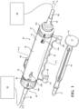
- the device 10 of the subject disclosure is configured to collect and process bone fragments in connection with various types of medical and/or surgical procedures. More specifically, the device 10 is configured to process and collect a composition 38 comprising bone fragments and other components (“the composition") from a patient.
- the composition is shown throughout the Figures as 38.
- the composition 38 is intended to be broadly construed to encompass all bone components regardless of their form, e.g. bone, tissues such as stem and progenitor cells, etc.
- the terms “bone fragments”, “bone dust”, and “the composition”, can be used interchangeably and share the broad construction set forth for the composition 38.
- the composition 38 is typically used to form bone graft.
- the composition 38 will include bone fragments, an irrigation solution, such as saline or water, blood, and one or more soft tissue fragments.
- the subject disclosure further provides a system, for use in collecting and processing bone fragments.
- the system includes a surgical tool 54 configured to harvest the composition 38 and shaped to couple with an intake tube 84.
- the surgical tool 54 is also configured to generate, e.g. grind, cut, shave, or abrade, bone to yield bone fragments.
- the system includes the surgical tool 54 which is configured to both generate bone fragments and harvest, i.e., aspirate, the composition 38.
- the system may also include the intake tube 84 through which the composition 38 is conveyed from the surgical tool 54 to the device 10 for collecting and processing bone fragments.
- the composition 38 is aspirated from the patient using the surgical tool 54, which causes the aspirated composition 38 to be collected in the device 10.
- the vacuum source 64 is in communication with the surgical tool 54 through the device 10 and one or more tubes.
- the device 10 includes an inlet cap 48, a housing 12 having a filter element 22 disposed therein, and an outlet cap 60.
- the outlet cap 60 is proximally coupled to the device 10, and a vacuum source 64 is coupled to the outlet cap 60 via an outlet tube 86.
- the outlet cap 60 is in fluid communication with the housing 12 and thus carries a vacuum airflow which aspirates the composition 38 from the patient and causes the subsequent collection of the composition 38 in the device 10.
- the inlet cap 48 is distally coupled to the device 10, and a surgical tool 54, e.g. a cutting device, is connected to the inlet cap 48 via an intake tube 84.
- the surgical tool 54 generates and subsequently aspirates the composition 38.
- the system may include a dedicated handheld aspirator in conjunction with a surgical tool 54, e.g. a cutting tool.
- the surgical tool 54 illustrated in Figure 1 is the aspirator, which will aspirate the composition from the surgical site, and the cutting tool (not separately shown) is used to separately generate the composition 38 from the patient.
- the inlet cap 48 is in fluid communication with the device 10 and receives the composition 38, which is subsequently deposited/injected into, and collected in a collection chamber 36 which is partially defined by the filter element 22.
- the inlet and outlet caps 48, 60 can be removed from the housing 12 and/or filter element 22 and the composition 38 can be harvested for use as bone graft.
- a plunger 78 can then be coupled to the piston 42 and force can be applied to the piston 42 via the plunger 78 to move the piston 42 from a first position 45 to a second position 46 and discharge the composition 38 collected in the collection chamber 36, i.e., the composition 38 can be harvested.
- the inlet cap 48 and the outlet cap 60 are configured to be coupled to one another and can thus be coupled together to restore vacuum airflow to the surgical tool 54.
- the collection chamber has a total volume of from about 5 to about 30, alternatively about 8 to about 25, alternatively from about 10 to about 20, cm 3 .
- Such collection chamber volumes allow for collection of an appropriate amount of composition 38, and also facilitate user friendly operation (handling) and harvesting (harvesting with minimal force) of the device 10.
- all values and ranges of values including and between those described above are hereby expressly contemplated for use herein.
- the device of this example includes the housing 12 and the filter element 22 at least partially disposed therein.
- the housing 12 includes a distal end 14, a proximal end 16, and an outer wall 18 having an outer surface 19 and an inner surface 20 extending between the distal and proximal ends 14, 16.
- the distal end 14 is generally closer to the patient, and the proximal end 16 is generally further from the patient, and proximal to the vacuum source 64.
- the housing 12 is cylindrical in shape and defines a volume.
- the housing 12 (and the filter element 22 for that matter) need not be cylindrical - and can thus have a cross-sectional profile other than circular, e.g. can have ovular, elliptical, or polygonal cross-sectional profile.
- the housing 12 is typically open-ended, unless the inlet and outlet caps 48, 60 are coupled to the respective distal and proximal ends 14, 16.
- the filter element 22 is partially disposed within the volume. In other words, at least a portion of the filter element 22 is positioned within the lumen of the housing 12.
- the filter element 22 includes a first end 24, a second end 26, and a sidewall 28 joining the first and second ends 24, 26.
- the first end 24 is positioned closer to the distal end 14 of the housing 12 than the second end 26, and the second end 26 is positioned closer to the proximal end 16 of the housing 12 than the first end 24.
- the filter element 22 is open-ended on both the first and second ends 24, 26.
- the filter element 22 is coupled to or secured within the housing 12 via a "snap fit" configuration.
- a "snap fit" configuration is illustrated wherein the first end 24 of the outer peripheral surface 32 of the sidewall 28 of the filter element 22 includes two posts 90 located opposite one another, while the outer wall 18 of the housing 12 includes two corresponding holes 91 into which the two posts 90 are snap fit or secured.
- the first end 24 of the outer peripheral surface 32 of the sidewall 28 of the filter element 22 includes a collar 82 extending radially around the distal end 14 of the housing 12 for alignment and sealing purposes.
- many different mechanisms can be used to couple the filter element 22 to the housing 12, and this is just one non-limiting example.
- a collar 82 can be utilized to secure the filter element 22 into the housing 12.
- the collar 82 is L-shaped and has an inner surface that includes a groove extending radially, and the outer wall of the housing 12 includes a corresponding rib extending radially.
- the collar 82 may be integral with the housing 12, the filter element 22, or may be a stand-alone component that joins the housing 12 to the filter element 22.
- the housing 12 and the filter element 22 can be sealed mechanically (as described above, interference fit, etc.) or with the use of an elastomeric (e.g. silicone rubber) sealing member.
- an elastomeric sealing member e.g. silicone rubber
- One example of use of the elastomeric sealing member would be the use of a groove and/or a flange (on the housing 12 and/or the filter element 22) in combination with an O-ring which sits between the housing 12 and the filter element 22.
- the housing 12, the filter element 22, the inlet cap 48, and/or the outlet cap 60 are sealed via the elastomeric (e.g. silicone rubber) sealing member(s).
- elastomeric sealing member e.g. silicone rubber
- One example of use of the elastomeric sealing member would be the use of a groove and/or a flange (on the housing 12 and/or the filter element 22) in combination with an O-ring which sits between the housing 12 and the filter element 22.
- Another example would be the use of the sealing member on the interior surface of the outlet cap 60 so that the outlet cap 60 has a robust seal when engaged with the device 10 and also a robust seal when engaged with the inlet cap 48 (when used to restore vacuum as described herein).
- the sidewall 28 of the filter element 22 defines an inner peripheral surface 30 and an outer peripheral surface 32 and has a plurality of apertures 34 therein.
- the sidewall 28 of the filter element 22 at least partially defines the collection chamber 36 for collection of the composition 38.
- the outer peripheral surface 32 of the sidewall 28 and the inner surface 20 of the outer wall 18 of the housing 12 are spaced apart from one another to define an exterior radial volume 40.
- the apertures 34 may take any suitable form, such as perforations, slots, etc.
- the outer peripheral surface 32 of the sidewall 28 may include one or more ribs 88 extending longitudinally from the first end 24 toward the second end 26 of the filter element 22.
- the ribs 88 which abut the inner surface 20 of the outer wall 18 of the housing 12 function to strengthen the outer wall 18 and maintain the exterior radial volume 40.
- the ribs 88 can be continuous or discontinuous. Discontinuous ribs 88 may also be referred to as fins.
- the example of Figures 3, 4 , and 5A includes tri-tipped ribs 88. In some examples, where the ribs 88 are continuous, the ribs 88 provide separate fluid channels within the exterior radial volume 40.
- the ribs 88 may be formed on the inner surface 20 of the housing 12 and can be just as previously described.
- the sidewall 28 of the filter element 22 also includes at least one bypass hole 70 in fluid communication with the exterior radial volume 40.
- at least one bypass hole 70 is larger than or has a larger diameter or area than the plurality of apertures 34 in the sidewall 28 of the filter element 22.
- This at least one bypass hole 70 is positioned so that when the inlet cap 48 is removed, vacuum airflow can be maintained since a fluid communication path can be established through the at least on bypass hole 70, into the exterior radial volume 40 (the volume between the outer peripheral surface 32 of the filter element 22 and the inner surface 20 of the outer wall 18 of the housing 12) and out of the outlet cap 60, without overly drying out the composition 38. It is useful, in certain configurations, to prevent the moisture content of the composition 38 from being lowered too much as maintaining sufficient moisture content has shown to be beneficial for cell viability.
- the filter element 22 is partially within the volume defined by the housing 12. Further, within the filter element 22 is the partially-defined collection chamber 36 (a defined sub-volume) and between the filter element 22 and the housing 12 lies the exterior radial volume 40 (another defined volume).
- the composition 38 typically follows a primary communication path through the inlet cap 48 and into the collection chamber 36, wherein excess fluid is drawn through the plurality of apertures 34, into the exterior radial volume 40, and out of the outlet cap 60. It should be appreciated that, once the composition 38 is drawn into the collection chamber 36 of the filter element 22, filtrate is drawn through the plurality of apertures 34 in the sidewall 28 of the filter element 22, and out of the outlet cap 60.
- the filter element 22 functions as a filter to further remove filtrate (liquid) components from the composition 38 and thus change the composition 38.
- the components and properties of the composition 38 e.g. irrigation solution, blood, excess soft tissue, etc.
- the amount of time the composition 38 spends in the filter element 22, the surface area and patterning of the plurality of apertures 34, and the strength of the vacuum all impact the physical characteristics of the "plug" of composition 38 which is formed in the filter element 22.
- the plurality of apertures 34 collectively open from about 0.5 to about 25, alternatively from about 0.6 to about 10, alternatively from about 0.6 to about 5, alternatively from about 0.7 to about 2, alternatively from about 0.8 to about 1.2, % of a total surface area of the inner peripheral surface 30 of the sidewall 28 of the filter element 22 to optimize hydration (prevent dehydration or excess-hydration) of the composition 38 collected in the collection chamber 36.
- the plurality of apertures 34 are uniformly spaced about the sidewall 28 of the filter element 22.
- the plurality of apertures 34 are patterned in groups or lines to optimize the hydration of the composition 38 collected in the collection chamber 36.
- the apertures can be circular and have a diameter of from about 0.2 to about 2.00, alternatively from about 0.4 to about 1.5, alternatively from about 0.6 to about 1.2, mm.
- the outer peripheral surface 32 of the sidewall 28 may include from about 40 to about 200, alternatively from 80 to about 140, alternatively from about 100 to about 120 apertures 34.
- the apertures can have shapes other than round as well, e.g. ovular, elliptical, or polygonal shape. In various non-limiting examples, all values and ranges of values including and between those described in the paragraph above are hereby expressly contemplated for use herein.
- the plurality of apertures 34 are patterned in lines to optimize the hydration of the composition 38 collected in the collection chamber 36.
- Figure 4 shows the plurality of apertures 34 arranged in a pattern of diagonal or helical lines in the sidewall 28 of the filter element 22.
- the plurality of apertures 34 could be arranged in a pattern of perpendicular lines (not shown in the drawings) in the sidewall 28 of the filter element 22.
- each line can have from about 2-12, alternatively from about 2-4 holes therein.
- the plurality of apertures 34 (e.g. lines) can be dispersed relatively evenly across, e.g. spread out on the filter element 22, or dispersed as to progressively increase or decrease longitudinally from the first end 24 toward the second end 26 of the filter element 22.
- a piston 42 is moveably disposed within the filter element 22.
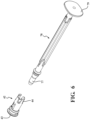
- the piston 42 includes a piston element 43, which pushes the plug of the composition 38 out of the collection chamber 36, and a plunger mount 44 opposite the piston element 43 and outside of the collection chamber 36, which cooperates with a corresponding attachment element 77 on the plunger 78 to connect thereto.
- the plunger mount 44 and the corresponding attachment element 77 are shaped to snap fit with one another.
- the plunger mount 44 and the corresponding attachment element 77 are shaped in any way suitable to releasably couple to one another.
- the piston 42 is movable between a first position 45 and a second position 46.
- the piston 42 In the first position 45, the piston 42 at least partially defines the collection chamber 36.
- the piston 42 in conjunction with the sidewall 28 of the filter element 22 defines the end and sidewalls of the collection chamber 36 when the piston 42 is in the first position 45.
- the piston 42 functions as a movable end wall of the collection chamber 36.
- the piston 42 In the first position 45, the piston 42 is located proximate to the second end 26 of the filter element 22, and the volume defined by the collection chamber 36 is at a maximum.
- the piston 42 In the second position 46, the piston 42 may be located proximate the first end 24 of the filter element 22, and the volume defined by the collection chamber 36 is at a minimum.
- a flange extends radially about the inner peripheral surface 30 of the sidewall 28 of the filter element 22 at its second end 26 such that the piston 42 abuts the flange when the piston 42 is in the first position 45.
- the piston 42 is profiled such that it includes a radial protrusion that abuts the second end 26 of the sidewall 28 of the filter element 22 which has a tapered portion 80 that is tapered radially inward.
- the tapered portion 80 allows more space in the exterior radial volume 40 at the proximal end of the device 10 for debris (e.g.
- the tapered portion 80 allows for a generous lead into the piston 42 when it is in the first position 45 or being assembled into the device 10 so that the piston 42 can be it seated correctly into the filter element 22 and does not get hung up as it can with as flange.
- the piston 42 includes a front face (radial protrusion) which provides a flat, round surface slideablly engaged in the collection chamber 36 to push the composition 38 therethrough.
- the second radial protrusion acts to provide a second barrier for the composition 38 and stabilizes the piston 42 and plunger 78 thereon as they are pushed through the collection chamber 36 to discharge the composition 38.
- additional distal protrusions (behind the first two protrusions), extending radially around the piston 42 and are used to distally secure the piston 42 within the device 10 during shipping and handling. Such protrusions may extend beyond the clearance radius.
- the inlet cap 48 is configured (or shaped) to be releasably coupled to either the distal end 14 of the housing 12 or the first end 24 of the filter element 22. In the examples shown throughout the Figures, the inlet cap 48 is releasably coupled to the first end 24 of the filter element 22. However, it should be appreciated that, in various alternative examples, the inlet cap 48 could be releasably coupled to (or configured to be releasably coupled to) the distal end 14 of the housing 12.
- the inlet cap 48 includes a body 50, an intake port 52 extending from the body 50 and configured to be coupled to the surgical tool 54, and a spout 56 extending from the body 50 opposite the intake port 52.
- the spout 56 includes an injection port 58 extending beyond the first end 24 of the filter element 22 and into the collection chamber 36 of the filter element 22.
- the inlet cap 48 is configured to receive the composition 38.
- the intake port 52 is typically connected to the surgical tool 54 via the intake tube 84. The composition is drawn through the surgical tool 54, through the intake tube 84, and into the intake port 52 of the inlet cap 48. The composition 38 moves through the body 50 of the inlet cap 48, through the spout 56, and out of the injection port 58 and into the collection chamber 36.
- the injection port 58 of the spout 56 extends into the collection chamber 36 at the first end 24 of the filter element 22, and in some examples, into the collection chamber 36 at the first end 24 of the filter element 22 such that the injection port is located proximally (or past) where the apertures 34 are first located on the sidewall 28 of the filter element 22.
- the spout 56 extends into the collection chamber 36 at the first end 24 of the filter element 22 such that the injection port is located distally (or before) where the apertures 34 are first located on the sidewall 28 of the filter element 22.
- the spout 56 (and a first collar 67 either on the spout 56 or on a vacuum spacer 66) ensures that the composition 38 is delivered into the filter element 22, and also results in a minimal amount of the composition 38 falling out of the device 10 when the inlet cap 48 is removed.
- the spout 56 helps to project the composition 38 into the filter element 22 towards the piston 42.
- the spout 56 also helps with the stopping of the vacuum airflow when full. Once the end of the spout 56 is backed up with the composition 38, the flow gradually reduces to below acceptable levels.
- the outlet cap 60 is configured (or shaped) to be releasably coupled to either the proximal end 16 of the housing 12 or the second end 26 of the filter element 22. In the examples shown throughout the Figures, the outlet cap 60 is releasably coupled to the proximal end 16 of the housing 12. However, it should be appreciated that, in various alternative examples, the outlet cap 60 could be releasably coupled to the second end 26 of the filter element 22. Further, the outlet cap 60 includes a vacuum port 62 configured to be coupled to a vacuum source 64. Typically, the vacuum port 62 is connected to the vacuum source 64 via the outlet tube 86. As such, the outlet cap 60 is in fluid communication with the device 10.
- the inlet cap 48 includes the body 50, the intake port 52 extending from the body 50, and a spout 56 extending from the body 50 opposite the intake port 52.
- the inlet cap 48 cooperates with the vacuum spacer 66 which is positioned around the outer periphery of the spout 56.
- the spout 56 is like a finger and the vacuum spacer 66 is like a ring that fits on the finger.
- an exterior radial surface of the spout 56 is shaped to cooperate with an interior radial surface of the vacuum spacer 66.
- the vacuum spacer 66 includes the two collars 67, 68.
- the first collar 67 extends radially around the spout 56 and abuts an inner peripheral surface of the inlet cap 48 when the inlet cap 48 is coupled to the distal end 14 of the housing 12 or the first end 24 of the filter element 22.
- the second collar 68 extends radially around the spout 56 towards, but does not abut, the inner peripheral surface 30 of the of the sidewall 28 of the filter element 22 when the inlet cap 48 is coupled to the distal end 14 of the housing 12 or the first end 24 of the filter element 22.
- the inlet cap 48 and spout 56 is molded as one piece and the vacuum spacer 66 including the collars 67, 68 is molded as another piece and then coupled (e.g. press fit, ultrasonically welded, or adhesively bonded (e.g. glued)) to a collar on the spout 56.
- This design creates an airtight join and simplifies the molding and assembly of the inlet cap 48. That is, the vacuum spacer 66 allows for efficient molding of the inlet cap 48 and efficient assembly of the device 10.
- the first collar 67 partially defines the collection chamber 36 and functions to prevent the device 10 from collecting any of the composition 38 substantially distal the injection port 58, which minimizes loss of the composition 38 and makes removal of the inlet cap 48 a neater process.
- the device 10 may also include a second collar 68 spaced apart from the first collar 67 and located closer to the intake port 52 than the first collar 67.
- the second collar 68 extends radially around the injection port 58 towards, but does not abut, the inner peripheral surface 30 of the of the sidewall 28 of the filter element 22.
- the second collar 68 helps (1) align the inlet cap 48 and the outlet cap 60 when coupled to one another and (2) supports the collar 67 during coupling of the inlet cap 48 and the outlet cap 60 and also once the inlet cap 48 and the outlet cap 60 are coupled.
- the second collar 68 may also help ensure that the device 10 ceases vacuum once the collection chamber 36 of the filter element 22 is filled with the composition 38, prevents the composition 38 from seeping between the collars 67, 68 and into a secondary fluid communication path once the composition 38 fills the collection chamber 36 of the filter element 22 thus preventing loss of the collected composition 38 through the at least one bypass hole 70 when the inlet cap 48 is connected to the filter element 22.
- the secondary fluid communication path runs through at least one bypass hole 70, between the inner surface 20 of the housing 12 and the outer peripheral surface 32 of the filter element 22 and into the exterior radial volume 40, and out of the outlet cap 60.
- the at least one bypass hole 70 is located on the sidewall 28 of the filter element 22 such that, when the inlet cap 48 is coupled to the filter element 22, the at least one bypass hole 70 is located between the first and second collars 67, 68 of the vacuum spacer 66.
- the at least one bypass hole 70 (in the example of Figure 2A plurality of bypass holes 70) between the collars 67, 68 allows for vacuum airflow to be re-established when the inlet cap 48 is removed from the device 10 filled with the composition 38. That is, the at least one bypass hole 70 provides the secondary fluid communication path once the collection chamber 36 of the filter element 22 of the device is full and the inlet cap is removed.
- the secondary fluid communication path between the outer peripheral surface 32 of the filter element 22 and the inner surface 20 of the housing 12 is routed around the composition 38 collected in the collection chamber 36 of the filter element 22 to ensure that the composition 38 collected in the collection chamber 36 of the filter element 22 is not overly dried when the inlet cap 48 is removed from the device 10 and the outlet cap 60 is still drawing vacuum.
- a further benefit of the at least one bypass hole 70 is that any liquids accumulated between the housing 12 and the filter element 22 can be easily drained from the device 10 through the outlet cap 60 with vacuum airflow which is reestablished through the secondary fluid communication path.
- this device 10 do not include a vacuum spacer 66, just the two collars 67, 68.
- the first collar 67 extends from and radially around the spout 56 and abuts an inner peripheral surface of the inlet cap 48 when the inlet cap 48 is coupled to the distal end 14 of the housing 12 or the first end 24 of the filter element 22 and the second collar 68 extends from and radially around the spout 56 towards, but does not abut, the inner peripheral surface 30 of the of the sidewall 28 of the filter element 22 when the inlet cap 48 is coupled to the distal end 14 of the housing 12 or the first end 24 of the filter element 22.
- Figures 10A and B and 11A and B illustrate two different examples of the device 10 that does not include the vacuum spacer 66, just the two collars 67, 68.
- Figures 10 A and B illustrate an example of the device 210 having an inlet cap 248 that that does not include the vacuum spacer 66 and that ceases to allow vacuum air flow once the collection chamber 236 is filled with the composition 38.
- Figures 11 A and B illustrates an example of the device 310 having an inlet cap 348 that does not include the vacuum spacer 66 and that allows for the overflow of the composition 38 and maintains vacuum airflow when the collection chamber 336 fills up with the composition 38.
- the device 210 may also include the second collar 268 spaced apart from the first collar 267 and located closer to the intake port 252 than the first collar 267.
- the second collar 268 also extends radially around the spout 256 and abuts the inner peripheral surface 230 of the sidewall 228 of the filter element 222 when the inlet cap 248 is coupled to the distal end 214 of the housing 212 or the first end 224 of the filter element 222.
- the at least one bypass hole 270 is located on the sidewall 228 of the filter element 222 such that, when the inlet cap 248 is coupled to the filter element 222, the at least one bypass hole 270 is located between the first and second collars 267, 268 of the spout 256.
- the at least one bypass hole 270 located on the sidewall 228 of the filter element 222 is different than a plurality of apertures 234 also found on the sidewall 228 of the filter element 222. As such, the at least one bypass hole 270 does not function until the inlet cap 248 is decoupled and the ceases to allow vacuum air flow once the collection chamber 236 is filled with the composition 38.
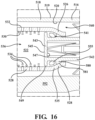
- the device 310 illustrated includes the inlet cap 348 having the first and second collars 367, 368 which extend radially around the spout 356 and abut the inner peripheral surface 330 of the sidewall 328 of the filter element 322 when the inlet cap 348 is coupled to the distal end 314 of the housing 312.
- the at least one bypass hole 370 is located on the sidewall 328 of the filter element 322 such that, when the inlet cap 348 is coupled to the filter element 322, the at least one bypass hole 370 is located between the first and second collars 367, 368 of the spout 352.
- the at least one bypass hole 370 located on the sidewall 328 of the filter element 322 is different than a plurality of apertures 334 also found on the sidewall 328 of the filter element 322.
- the injection port 358 of the spout 356 includes at least one corresponding bypass hole 372, wherein the corresponding bypass hole 372 is located between the first and second collars 367, 368 of the spout 356 and thus in communication with the at least one bypass hole 370 located on the sidewall 328 of the filter element 322 when the inlet cap 348 is coupled to the filter element 322 such that a secondary fluid communication path is provided.
- the overflow fluid path runs through wherein the corresponding bypass hole 372, between the first and second collars 367, 368, the at least one bypass hole 370, through the corresponding at least one bypass hole 372, into the exterior radial volume 340, and out of the outlet cap 360 and thus provides an over flow path for the composition 38 and maintains vacuum airflow when the filter element 322 fills up with the composition 38.
- the inlet cap 348 is designed to maintain vacuum airflow once the collection chamber 336 is filled with the composition 38.
- the device 10 includes a vacuum spacer 66 some examples can include a vacuum spacer which includes a third bypass hole to allow the device 10 to maintain vacuum airflow once the collection chamber 36 is filled with the composition 38.
- the device optimizes the hydration of the "plug" of the composition 38 in the collection chamber 36 which also makes discharge easier because the composition 38 does not flow around or enter into a gap between the face of the piston 42 and the sidewall 28 of the filter element 22, where the gap in size increases as the piston 42 moves from the first position 45 to the second position 46.
- the composition 38 is hydrated sufficiently, making the effective size of the bone fragments large enough in at least one dimension such that the composition 38 does not flow around or enter into a gap between the face of the piston 42 and the sidewall 28 of the filter element 22, where the gap in size increases as the piston 42 moves from the first position 45 to the second position 46.
- the cross-sectional area of the piston 42 and/or cross-sectional of the filter element 22 may be adjusted such that the size of the gap is small enough to prevent bone fragments from moving therethrough.
- Figure 5A is an exploded perspective view of the device 10 of Figure 1 and Figure 5B is an exploded cross-sectional view of the device 10 of Figure 5A .
- Figure 5B also illustrates the tapered sidewall 28 of the filter element 22 of the example of Figure 1 .
- the device 10 includes a plunger 78 configured to be releasably coupled to the piston 42 to move the piston 42 between the first and second positions 45, 46.
- the plunger 78 includes the corresponding attachment element 77 and also a press pad 79.
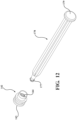
- Figure 6 an isolated perspective view of a plunger 78 and a piston 42 of the device of Figure 1 , which are configured to be releasably coupled via a "snap fit" to one another, are illustrated.
- the corresponding attachment element 77 of the plunger 78 and a piston attachment element of the plunger mount 44 are shaped to releasably couple to one another via various interfaces including, but not limited to, a threadable interface, such as with a bayonet joint, a "snap fit" interface, etc.
- a plunger 178 and a piston 142 which are configured to be threadably coupled to one another is illustrated.
- a corresponding attachment element 177 of the plunger 178 and a plunger mount 144 of the piston 142 are threaded.
- the press pad 179 of the plunger 178 can be pressed to move the piston 142 such that the front face 143 pushes a plug of the composition 38 out of the device 10.
- the plunger 78 can be coupled to the piston 42. Force can be applied to the plunger 78 to move the piston 42 from the first position 45 to the second position 46 to discharge the composition 38 from the collection chamber 36 of the filter element 22.
- the plunger 78 can also be used to move the piston 42 back to the first position 45, i.e., retract the position, and then be decoupled from the piston 42. Once the plunger 78 is decoupled from the piston 42, the caps 48, 60 can be removed and the process can be repeated to harvest and discharge more of the composition 38.
- the inlet cap 48 and the outlet cap 60 are configured to be coupled to one another such that after the composition 38 is acquired through the intake port 52 and collected in the collection chamber 36 and the inlet cap 48 and the outlet cap 60 have been removed from the filter element 22 and/or the housing 12 to harvest the composition 38, the inlet cap 48 and the outlet cap 60 can be coupled to one another to restore vacuum airflow to the surgical tool 54.
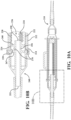
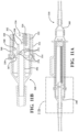
- Figures 8A and 8B and 9A and 9B illustrate the coupling of the inlet cap 48 and the outlet cap 60.
- the vacuum spacer 66 includes the first and second collars 67, 68, as well as a J-notch post 110.
- the inlet cap 48 and the outlet cap 60 can be coupled by inserting the J-notch post 110 of the vacuum spacer 66 on the spout 56 of the inlet cap 48 into a J-notch 112 of the outlet cap 60 and rotating the inlet cap 48 to releasably couple the inlet cap 48 to the outlet cap 60, an indicium 116 on the outlet cap 60 and the indicium 106 on the inlet cap 48 line-up to indicate that the outlet cap 60 and the inlet cap 48 are fully engaged.
- the vacuum spacer 66 ensures that when the inlet and outlet caps 48, 60 are coupled to one another to restore vacuum airflow there is a seal between the inlet and outlet caps 48, 60 to prevent the accumulation of fluid therebetween, while the spout 56 provides a bridging lumen between the inlet and outlet caps 48, 60.
- the inlet cap 48 (the body 50 and/or the spout 56) may also include the first collar 67, the second collar 68, and/or a J-notch post 110.
- the first and second collars 67, 68 could extend radially around the spout 56 and the J-notch post 110 could also be located on the spout 56 or body 50.
- the inlet cap 48 and the outlet cap 60 are configured (or shaped) to be releasablly coupled to the filter element 22 and/or the housing 12.
- the inlet and outlet caps 48, 60 can be coupled to the device 10 via mechanical know in the art (e.g. snap fit, J-notch, and other mechanical couplings.
- the inlet cap 48 is releasably coupled to the first end 24 of the filter element 22.
- a J-notch post 104 on the first end of the filter element 22 cooperates with a J-notch 102 on the inlet cap 48 to couple the inlet cap 48 to the device 10.
- an indicium 106 on the inlet cap 48 lines-up with an indicium 108 on the housing 12 to indicate that the inlet cap 48 is fully engaged with the device 10.
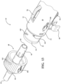
- FIG. 13 an example of the device 10 with an alternative inlet cap 48 is releasably coupled to the first end 24 of the filter element 22.
- a "tear drop" shaped J-notch post 105 on the first end 24 of the filter element 22 is shown.
- the J-notch post 105 provides more contact with the J-notch 102 and more robust engagement/coupling between the inlet cap 48 and the filter element 22.
- the device includes J-notch posts of various cross-sectional profiles e.g. round, ovular, elliptical, polygonal, or tear-drop shaped as shown in Figure 13 .
- a friction button 103 on the first end 24 of the filter element 22 is shown.
- the friction button 103 sits at a mouth of the J-notch 102 to prevent the inlet cap 48 from moving, thereby ensuring that the inlet cap 48 maintains full engagement with the device 10 (i.e. is not loosened during shipping and collection).
- the "tear drop" shaped J-notch post 105 on the first end 24 of the filter element 22 is also effective at keeping the inlet cap 48 coupled tightly to the filter element 22 during shipping and collection.
- the outlet cap 60 is releasablly coupled to the proximal end 16 of the housing 12.
- the outlet cap 60 has the J-notch 112 therein and the proximal end of the outer wall 18 of the housing 12 has a J-notch post 114 thereon.
- the indicium 116 on the outlet cap 60 and an indicium 118 on the housing 12 line-up to indicate that the outlet cap 60 and the housing 12 are fully engaged.
- a method of collecting and processing bone fragments with the device 10 is also disclosed herein.
- the method utilizes various examples of the device 10 as described above and includes the steps of: providing the device 10; acquiring the composition 38 through the inlet cap 48; collecting the composition 38 in the filter element 22; decoupling the inlet cap 48 from the housing 12 or the filter element 22; decoupling the outlet cap 60 from the housing 12; applying a force in a first direction to move the piston 42 from the first position 45 to the second position 46 to discharge the composition 38 from the filter element 22; and applying a force in a second direction so that the device 10 can be used to harvest more of the composition 38.
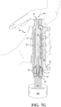
- Figures 7A-7G illustrate various steps which may be included in the method of collecting and processing bone fragments with the device 10.
- Figures 7A-7C provide a cross-sectional view of the device 10 of Figure 1 during the step of acquiring the composition 38 through the inlet cap 48.
- Figure 7A a cross-sectional view of the device of Figure 1 which illustrates the onset of collection of the composition 38.
- the composition 38 has started to collect in the collection chamber 36 of the device.
- Figure 7C illustrates the final stages of collection wherein the collection chamber 36 is just about full of the composition 38 comprising bone fragments.
- Figure 7D is a cross-sectional view of the device 10 of Figure 7C which illustrates the decoupled inlet cap 48, the filter element 22 within the housing 12 filled with the composition 38 now filtered, the outlet cap 60 coupled to the housing 12, and the decoupled plunger 78 which will be subsequently connected to the piston 42 so that force can be applied to the plunger 78 to move the piston 42 from the first position 45 to the second position 46 to discharge the composition 38 from the device 10.
- the step of decoupling the inlet cap 48 from the filter element 22 has occurred, and the step of decoupling the outlet cap 60 from the housing 12 will subsequently occur so that the piston 42 can be moved from the first position 45 to the second position 46 to discharge the composition 38 from the device 10.
- the method further includes the step of coupling the plunger 78 to the piston 42 such that force can be applied to the piston 42 via the plunger 78 to move the piston 42 from the first position 45 to the second position 46 and discharge the composition 38 collected in the collection chamber 36 of the filter element 22 and into a container 120.
- Figure 7E is a cross-sectional view of the device of Figure 7D with a decoupled inlet cap 48 to provide access so that the decoupled plunger 78 can be connected to the piston 42 and force can be applied to the plunger 78 to move the piston 42 from the first position 45 to the second position 46 to discharge the composition 38 from the device 10.
- the method further includes the step of decoupling the plunger 78 from the piston 42.
- the method may also include the steps of coupling the inlet cap 48 to the housing 12 or the filter element 22 and coupling the outlet cap 60 to the housing 12.
- the steps of acquiring, collecting, decoupling the inlet cap 48, decoupling the outlet cap 60, and applying a force in a first direction to move the piston 42 from the first position 45 to the second position 46 to discharge the composition 38 from the filter element 22 are repeated at least once so that additional amounts of the composition 38 can be harvested with the device 10.
- the method may further include the step of coupling the inlet cap 48 and the outlet cap 60 to one another to restore vacuum airflow to the surgical tool 54 subsequent to the steps of acquiring, collecting, decoupling the inlet cap 48, and decoupling the outlet cap 60.
- the device 10 includes the housing 12 having: (1) a piston rack 92; (2) a grip 94; and (3) a clip mount 96 (e.g. for a drape clip).
- the piston rack 92 is configured to hold the plunger 78 while not in use.
- the piston rack 92 includes a first and a second clamp 98, 100, which are configured to mechanically engage the plunger 78.
- the clamp(s) may be configured in a C-shape.
- Figure 7C illustrates the plunger 78 engaged in the piston rack 92
- Figure 7D illustrates the plunger 78 disengaged from the piston rack 92.
- the clamps may take the form of any suitable coupler configured to engage the plunger 78 while the piston 42 is not in use.
- the plunger 78 of the exemplary device of Figure 1 configured to releasably couple to the housing 12 of the device 10.
- the plunger 78 is shown decoupled from the device 10.
- the plunger 78 is shown mounted to the device 10 via the piston rack 92 located on the outer surface 19 of the outer wall 18 of the housing 12 which is shaped to cooperate with and releasably engage the plunger 78.
- the outer wall 18 of the housing 12 includes the plunger rack 92 comprising one or more features (in the example of Figure 1 , two features) which are shaped to releasably engage the plunger 78.
- the user can simply remove the plunger 78 from the piston rack 92 and couple the plunger 78 to the piston 42 so that the composition 38 can be discharged from the collection chamber 36 of the device 10 and ultimately harvested.
- the grip 94 when the plunger 78 is disengaged, and for use and coupled to the piston 42 so that force can be applied to the piston 42 via the plunger 78 to move the piston 42 from a first position 45 to a second position 46 and discharge the composition 38 collected in the collection chamber 36, the grip is 94 is disposed on the outer wall 18 of the housing 12, the grip 94 can be used. That is, when the force is being applied to plunger 78 to move the piston 42 from a first position 45 to a second position 46 and discharge the composition 38, a user can robustly secure the housing 12 with one hand on the grip 94, and actuate or apply force to the plunger 78 with their other hand to move the piston 42 and harvest the composition 38.
- the grip 94 e.g. with and without finger indents, comprising various "grip friendly" materials such as elastomers and foams are contemplated herein.
- the grip 94 facilitates user-friendly two-handed operation of the device 10, where a first hand is placed around the grip 94 and the other hand engages the plunger 78.
- the device can also include a grip 94.
- the grip may be part of the piston rack 92 or may be stand alone and located on the outer wall 18 of the housing 12.
- the grip 94 provides the user with improved control of the device 10 during the harvesting of the composition 38.
- the grip 94 which is part of the piston rack 92 in this example, is exposed so that when the piston 42 is coupled to the plunger 78 and force is applied to the plunger 78, the user can utilize the grip 94 to better hold the device 10 during the application of force to the plunger 78 and the ensuing discharge of the composition 38 from the collection chamber 36 of the device 10.
- the device may include a clip mount 96.
- a drape clip includes a clip which is configured to be releasably coupled to various surfaces, and fabrics in the operating room can be used with the clip mount 96.
- a spring-loaded V-drape clip is utilized; however, various other clip configurations known in the art can be used in lieu of the spring-loaded V-clip illustrated.
- the device 10 can be conveniently stored (mounted) and easily located and accessed.
- Figure 4 is an isolated perspective view of the filter element 22 of the device 10 of Figure 1 .
- the plurality of apertures 34 are patterned in diagonal lines in the sidewall 28 of the filter element 22 to optimize the hydration of the composition 38 collected in the collection chamber 36.
- the plurality of apertures 34 (e.g. lines) are dispersed relatively evenly across, e.g. spread out on the filter element 22.
- the outer peripheral surface 32 of the sidewall 28 includes two tri-tipped ribs 88 extending longitudinally from the first end 24 toward the second end 26 of the filter element 22.
- the device 10 of Figure 1 includes the inlet cap 48 with the J-notch 102 (a first rotational coupler) therein, and the outer peripheral surface 32 of sidewall 28 of the first end 24 of the filter element 22 has the J-notch post 104 (second rotational coupler) thereon.
- the inlet cap 48 has a female configuration
- the first end 24 of the filter element 22 has a male configuration.
- the J-notch post 104 (second rotational coupler) of the first end 24 of the filter element 22 is inserted and rotated into the J-notch 102 (first rotational coupler) of the inlet cap 48 to releasably couple the filter element 22 to the inlet cap 48, the indicium 106 on the inlet cap 48 and the indicium 108 on the housing 12 line-up to indicate that the inlet cap 48 and the housing 12 are fully engaged (i.e., are sufficiently rotated relative to one another such that the two are fully engaged).
- the inlet cap 48 of this example cooperates with the vacuum spacer 66, which also has the J-notch post 110 thereon.
- the device 10 includes the outlet cap 60 with the J-notch 112 therein, and the proximal end of the outer wall 18 of the housing 12 has the J-notch post 114 thereon.
- the outlet cap 60 has a female configuration, and the proximal end 16 of the housing 12 has a male configuration.
- the J-notch post 114 of the proximal end of the outer wall 18 of the housing 12 is inserted and rotated into the J-notch 112 of the outlet cap 60 to releasably couple the housing 12 to the outlet cap 60, the indicium 116 on the outlet cap 60 and the indicium 118 on the housing 12 line-up to indicate that the outlet cap 60 and the housing 12 are fully engaged.
- the J-notch and j-notch posts shown throughout this disclosure may have other suitable geometries that are coupled of facilitating rotational coupling between the caps 48, 60 and the housing 12, and between the caps 48, 60 themselves.
- any form of rotational coupler may be used interchangeably with the various j-notch and post configurations described above, so long as one of the components has a male rotational coupler configuration and the other component has a female rotational coupler configuration. Frictional engagement between the inlet and outlet caps 48, 60 and the housing 12, and between the inlet and outlet caps 48, 60 themselves is also contemplated.
- the device 510 includes a housing 512, a filter element 522, an inlet cap 548, and an outlet cap 560.
- the device 510 includes the housing 512, which includes a distal end 514, a proximal end 516, and an outer wall 518 extending between the distal and proximal ends 514, 516.
- the outer wall 518 has an outer surface 519 and an inner surface 520.
- the inlet cap 548 is shown releasably coupled to the distal end 514 of the housing 512 and/or a first end 524 of the filter element 522.
- the inlet cap 548 includes an intake port 552 configured to be coupled to a surgical tool and receive the composition comprising bone fragments, the filter element 522 collects the composition comprising bone fragments, and the outlet cap 560 is releasably coupled to the proximal end 516 of the housing 512 and includes a vacuum port 562 configured to be coupled to a vacuum source.
- a vacuum spacer 566 is shown separate from the inlet cap 548. The vacuum spacer 566 facilitates airtight connection of the inlet cap 548 to the device 510 and its separate fabrication simplifies molding and assembly of the inlet cap 548.
- the filter element 522 is at least partially disposed within the housing 512.
- the filter element 522 within the housing 512 of the device 510 is illustrated in phantom.
- the filter element 522 is shown partially disposed within the housing 512.
- the filter element 522 has the first end 524 and the second end 526, which are joined by a sidewall 528.
- the first end 524 is positioned closer to the distal end 514 of the housing 512 than the second end 526.
- the sidewall 528 has a plurality of filter apertures 534 and defines an inner peripheral surface 530 and an outer peripheral surface 532.
- the inner peripheral surface 530 of the sidewall 528 at least partially defines a collection chamber 536 for collection of a composition comprising bone fragments.
- the outer peripheral surface 532 of the sidewall 528 and the inner surface 520 of the outer wall 518 are spaced apart from one another to define an exterior radial volume 540.
- the composition typically follows a primary communication path through the inlet cap 548 and into the collection chamber 536, wherein excess fluid is drawn through the plurality of filter apertures 534, into the exterior radial volume 540, and out of the outlet cap 560.
- the composition is drawn into the collection chamber 536 of the filter element 522 and filtrate is drawn through a primary fluid communication path and out of the outlet cap 560.
- the sidewall 528 also has a proximal portion 535 adjacent the second end 526 which defines at least one drain aperture 555.
- the proximal portion 535 of the sidewall 528 of the filter element 522 is tapered radially inward.
- the device 510 of this example also includes a piston 542, part of which can be seen through a window portion 515 in the sidewall 528 of the device 510 in Figure 14 .
- the piston 542 includes a piston element 543 having a front face 545 and a back surface 547, a radial protrusion 580, and a plunger mount 544 opposite the piston element 543.
- the piston 542 is moveably disposed within the filter element 522. More specifically, the piston 542 is movable between a first and a second position. In the first position, the front face 545 of the piston element 543 at least partially defines the collection chamber 536 and the back surface 547, the plunger mount 544, and the inner peripheral surface 530 of the proximal portion 535 of the sidewall 528 define an interior radial volume 541. Further, in the first position, the front face 545 is within the filter element 522 and spaced distally relative to the second end 526 of the filter element 522 and the at least one drain aperture 555 places the exterior radial volume 540 and the interior radial volume 541 in fluid communication.
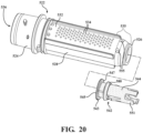
- Figure 18 shows an isolated view of the piston 542 disposed in the filter element 522 in the first position
- Figure 19 shows a cross-sectional view of the piston 542 and the filter element 522 of claim
- Figure 20 shows an exploded view of the piston 542 and the filter element 522 of claim 18.
- the composition is acquired through the inlet cap 548 and collected in the collection chamber 536.
- the plurality of filter apertures 534 and exterior radial volume 540 provides the primary fluid communication path with the vacuum source.
- a supplementary fluid communication path with the vacuum source runs around a perimeter of the piston element 543, through the interior radial volume 541, out the at least one drain aperture 555, and into the exterior radial volume.
- the radial protrusion 580 of the filter element 522 has a top surface 581 that is tapered radially inward.
- the top surface 581 of the radial protrusion 580 abuts the inner peripheral surface 530 of the proximal portion 535 of the filter element 522, which is also tapered radially inward.
- the radial protrusion 580 abuts the inner peripheral surface 530 of the proximal portion 535 of the filter element 522 when the piston 542 is in the first position.
- the piston element 543 of the piston 542 is spaced radially inwardly from the inner peripheral surface 530 of the sidewall 528 of the filter element 522 to define a radial drain gap 549.
- the radial drain gap 549 is a distance from the inner diameter of the filter element 522 to an outer diameter of the front face 545 of the piston element 543.
- the radial drain gap 549 is from 0.5 to 1, from 0.1 to 0.85, from 0.1 to 0.6, or from 0.14 to 0.54, mm when the piston 542 is in the first position.
- all gap width values and ranges of values including and between those described in the paragraph above are hereby expressly contemplated for use herein.
- the at least one drain aperture 555 on the proximal portion 535 of the sidewall 528 of the filter element 522 opens from 5 to 55 or from 5 to 25, % of a total surface area of an exterior peripheral surface of the proximal portion 535 of the sidewall 528.
- all surface area values and ranges of values including and between those described in the paragraph above are hereby expressly contemplated for use herein.
- the proximal portion 535 of the sidewall 528 of the filter element 522 has from 2 to 10, from 2 to 8, or from 2 to 6 drain apertures 555.
- the filter element 522 shown in Figures 17-20 has 4 drain apertures 555.
- the drain apertures 555 can have various shapes, e.g. ovular, elliptical, or polygonal shape. In a typical example the at least one drain aperture 555 is elliptical in shape, e.g. round. When more than one drain aperture 555 is included on the sidewall 528, the drain apertures 555 can have different shapes.
- each of the at least one drain apertures 555 can have a diameter of from 0.1 to 4.5, or from 1.5 to 3.5, or from 2.8 to 3.2, mm.
- a diameter of each of the plurality of filter apertures 534 is from 0.1 to 2.5, from 0.75 to 1.25, or from 0.84 to 1.14, mm.
- all diameter values and ranges of values including and between those described in the paragraph above are hereby expressly contemplated for use herein.
- Each of the at least one drain apertures 555 typically has a larger size than each of the plurality of filter apertures 534.
- each of the at least one drain aperture 555 has a drain aperture 555 diameter at least two times larger than a filter aperture diameter of each of the filter apertures 534 in the sidewall 528 of the filter element 522.
- the at least one drain aperture 555 (1) prevents collection of filtrate in the interior radial volume 541 and (2) provides improved filtration and drainage.
- the supplementary fluid communication path runs through the radial drain gap 549, into the interior radial volume 541, out of the at least one drain apertures 555, into the exterior radial volume 540, and out of the outlet cap 560. That is, during use, the composition is drawn into the collection chamber 536 of the filter element 522 and filtrate is drawn through a supplementary fluid communication path and out of the outlet cap 560. As such, it provides an alternative fluid passage to the primary fluid communication path.
- the radial drain gap 549 is particularly effective because it provides drainage continuously along the inner peripheral surface 530 of the sidewall 528 of the filter element 522.
- the continuous profile of the radial drain gap 549 and the larger size of the at least one drain aperture 555 make the supplementary fluid communication path surprisingly effective.
- the device 510 includes a plunger 578 configured to be releasably coupled to the piston 542 to move the piston 542 between the first and second positions. That is, upon removal of the inlet cap 548 and the outlet cap 560, the plunger 578 can be coupled to the piston 542, and force can be applied to the piston 542 to move the piston 542 from the first position to the second position to discharge composition from the filter element 522.
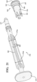
- the plunger 578 includes a corresponding attachment element 577, a press pad 579, and a body 583 extending therebetween.
- the press pad 579 of this disclosure could also be described as a handle and can be broadly interpreted as a surface to which force can be applied to the plunger 578 to move the piston 542 from the first position to the second position.
- the plunger mount 544 of the piston 542 includes an attachment element 551 that is shaped to releasably couple to the corresponding attachment element 577 of the plunger 578 to couple the plunger 578 to the piston 542.
- the body 583 of the plunger 578 is tapered such that a diameter of the body 583 increases as the body 583 extends from the corresponding attachment element 577 towards the press pad 579. Still referring to Figure 21 , in some examples, the body 583 is tapered such that a diameter of the body 583 increases as the body 583 extends from the corresponding attachment element 577 towards the press pad 579. Further, the body 583 of the plunger 578 includes a plurality of ribs 585. The ribs 585 reduce the plastic content and the cost while having an I-beam like strengthening effect on the plunger 578. In the example of Figure 14 , the body 583 includes 4 tapered ribs 585.
- This tapering provides an interference fit which slows down the plunger 578 as it progresses through an opening at the second end 526 of the filter element 522 as the piston 542 is driven from the first position to the second position to eject composition/bone fragments collected in a controlled manner.
- the body 583 having a tapered profile prevents the plunger 578 and the piston 542 from violently shooting through the collection chamber 536 of the filter element 522 and out of the housing 512 of the device 510, which minimizes potential for the disconnection of the piston 542 and plunger 578 and/or an uncontrolled ejection of the composition collected out of the device 510. It should be appreciated that this plunger 578, with its tapered body 583, can be employed with any of the example devices described herein.
- the increase of diameter of the body 583 of the plunger 578 as the body 583 extends from the corresponding attachment element 577 towards the press pad 579 is illustrated.
- the diameter 576a of the body 583 proximal the press pad 579 is larger than the diameter 576b of the body 583 proximal the corresponding attachment element 577.
- the tapering is accomplished via decreasing a width of the ribs 524 as they extend from the press pad 579 to the corresponding attachment element 577. It should be appreciated that the tapering can be consistent or inconsistent, e.g. with steps. In such examples, force that is required to be applied to the plunger 578 to move the piston 542 progressively increases as a plunger 578 is used to move the piston 542 between the first and second positions.
- the outer wall 518 of the housing 512 of the device 510 has the window portion 515 which allows light to pass therethrough.
- the window portion 515 is typically located closer to the proximal end 516 of the housing 512 than to the distal end 514 of the housing 512.
- the window portion 515 is transparent.
- various examples of the device 510 may utilize the window portion 515 which is translucent, e.g. offers limited visibility.
- the window portion 515 is transparent. As such, the internal components of the device 510 are visible through the window portion 515.
- the outer wall 518 includes a remaining portion in addition to and different than the window portion 515. In such examples, the remaining portion is translucent or opaque.
- the piston 542 is at least partially visible through the window portion 515 in the outer wall 518 of the housing 512.
- the attachment element 551 of the plunger mount 544 of the piston 542 is visible through the window portion 515.
- the plunger 578 can be coupled to the piston 542 while being viewed through the window portion 515.
- the visible engagement is user friendly and facilitates the proper and efficient use of the device 510.
- the attachment element 551 of the piston 542 is shaped to snap fit couple to the corresponding attachment element 577 of the plunger 578 to couple the plunger 578 to the piston 542.
- the attachment element 551 of the piston 542 is shaped to threadedly couple to the corresponding attachment element 577 of the plunger 578 to couple the plunger 578 to the piston 542.
- the attachment element 551 of the piston 542 has a visual identifier and at least a portion of the corresponding attachment element 577 of the plunger 578 has a corresponding visual identifier that produce a visual association between the attachment element 551 of the piston 542, which is visible through the window portion 515 in the first position and the corresponding attachment element 577 of the plunger 578.
- the visual identifier can be corresponding indicia or even a matching color. The visual identifier and the corresponding visual identifier promote the insertion of the plunger 578 into the proximal end 516 of the housing 512, to further facilitate the proper and efficient use of the device 510.
- the visual identifier of the attachment element 551 of the piston 542 is a color
- the corresponding visual identifier of the corresponding attachment element 577 of the plunger 578 is the color
- remaining components of the bone dust collector are collectively colored to maintain the visual association between the attachment element 551 of the piston 542 and the corresponding attachment element 577 of the plunger 578.
- the visual identifier is a color represented by the stippling (dotted fill) of the plunger 578 and the piston 542. That is, in the example shown, the plunger 578 and the piston 542 are the same color as represented by the stippling, e.g. orange.
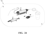
- a sterile bone collection device 511 and packaging system 700 is also disclosed.
- the sterile device 511 is just as described in the examples above but is sterilized.
- the sterile device 511 includes a housing 512 including the distal end 514, the proximal end 516, and the outer wall 518 having a plunger rack 592 thereon.
- the plunger 578 is engaged in the plunger rack 592
- the inlet cap 548 comprising the intake port 552 is releasably coupled to the distal end 514 of the housing 512
- the intake tube 584 is connected to the intake port 552
- the outlet cap 560 is releasably coupled to the proximal end 516 of the housing 512.
- This assembled configuration is user friendly and allows a user to quickly understand the sterile device 511 and its assembly and dis-assembly, which is required to use the plunger 578.
- the sterile device 511 is removed from the packaging system 700 with the intake tube 584 attached to the proper end (i.e. the inlet cap 548) of the sterile device 511.
- the sterile device 511 can be removed from the packaging system 700 and used immediately. That is, the sterile device 511 can be removed from the packaging system 700 and a surgical tool can be immediately attached and used. Handling of the sterile device 511 prior to surgery is minimized and efficient use during surgery is facilitated.
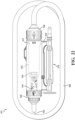
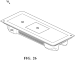
- the packaging system 700 includes an inner blister pack 702.
- the inner blister pack 702 includes an inner shell 704 that defines a sterile interior space 706 and that is configured to house the sterile device 511.
- the inner shell 704 includes a shell floor 708 and a shell sidewall 710 having the inner surface 712, an outer surface 714, and an ovular profile.
- the inner surface 712 of the shell sidewall 710 defines the sterile interior space 706 and houses the sterile device 511.
- the sterile device 511 is housed in the sterile interior space 706 with the intake tube 584 wrapped radially thereabout having an ovular circumferential profile that corresponds with the ovular profile of the shell sidewall 710.
- a holding band 718 configured to hold the sterile device 511 with the intake tube 584 wrapped radially thereabout together is included in the packaging system 700.
- an inner sealing film 716 cooperates with the inner shell 704 to seal the sterile device 511 within the inner blister pack 702.
- the inner sealing film 716 can have instruction graphics displayed thereon so that when a user opens the inner blister pack, presumably in a sterile zone, a user can refer to a sterile set of instructions for use.
- An inner sealing film 716 with instruction graphics displayed thereon is included in the appendix filed herewith.
- the sterile zone is a specific area in an operating room that is considered sterile and free of microorganisms. Maintaining the sterile zone is not an easy task because there are many chances for a breach in sterility during set-up, operation, and post-operation.
- the sterile device 511 including directions for use, can be utilized in a sterile and efficient manner right in the sterile zone of the operating room.
- the inner blister pack 702 with the directions thereon and the sterile device 511 therein can be conveniently positioned in the sterile zone on patient support apparatus or elsewhere before surgery.
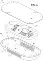
- the packaging system 700 may also include an outer blister pack 720.
- the outer blister pack 720 includes a barrier shell 722 that defines a sterile chamber 724 and that is configured to house the inner blister pack 702.
- a barrier sealing film 726 cooperates with the barrier shell 722 to seal the inner blister pack 702 within the outer blister pack 720.
- the barrier shell 722 includes a barrier floor 728 and a barrier sidewall 730 having an exterior surface 732 and an interior surface 734.
- the packaging system 700 may also include a packaging label 742.
- the barrier sidewall 730 includes one or more tabs 736 projecting radially inwardly from the barrier sidewall 730 into the sterile chamber 724 which cooperate with the outer surface 714 of the shell sidewall 710 of the inner shell 704 to secure the inner blister pack 702 in the sterile chamber 724 of the outer blister pack 720.
- the one or more tabs 736 can have a contact surface 738 which is shaped to releasably couple with a corresponding contact surface 740 on the outer surface of the shell sidewall 710.
- two of the tabs 736 have a ridged contact surface 738 which cooperates with a corresponding ridged contact surface 740 on the outer surface 714 of the shell sidewall 710 to secure the inner blister pack 702 within the sterile chamber 724 of the outer blister pack 720.
- Figure 26 is a perspective view of the packaging system 700 with the sterile bone collection device 511 therein.
Landscapes
- Health & Medical Sciences (AREA)
- Heart & Thoracic Surgery (AREA)
- General Health & Medical Sciences (AREA)
- Animal Behavior & Ethology (AREA)
- Veterinary Medicine (AREA)
- Public Health (AREA)
- Engineering & Computer Science (AREA)
- Biomedical Technology (AREA)
- Life Sciences & Earth Sciences (AREA)
- Vascular Medicine (AREA)
- Transplantation (AREA)
- Orthopedic Medicine & Surgery (AREA)
- Anesthesiology (AREA)
- Hematology (AREA)
- Physical Education & Sports Medicine (AREA)
- Oral & Maxillofacial Surgery (AREA)
- Cardiology (AREA)
- Prostheses (AREA)
- Filtering Of Dispersed Particles In Gases (AREA)
Abstract
Description
- This application claims priority to and all the advantages of
U.S. Provisional Patent Application No. 62/949,863, filed on December 18, 2019 - Conventional medical and surgical procedures routinely involve the use of systems and tools which allow surgeons to remove bone. Such systems often generate bone fragments (in many instances with a drill). Once removed, the bone fragments, collectively referred to as bone graft, can be used for reimplantation. In fact, the bone graft is particularly useful in various surgical procedures because it can be used to bridge gaps between bone segments and act as a scaffold for bone growth and subsequent bone fusion.
- In some surgical procedures, bone fragments are, as a matter of course, necessarily generated, harvested, and used as bone graft all in the same procedure. For example, spinal procedures (e.g. spinal fusion) require the drilling and removal of various spinal bone, and the subsequent use of bone graft. As another example, joint reconstruction and revision procedures require the drilling and removal of various bone, and the subsequent use of bone graft.
- In other surgical procedures, the bone fragments may be intentionally harvested, sometimes from bones in another area of the body, for use in the procedure that requires bone graft. In yet other procedures, bone graft comprising bone from another patient, a cadaver, or even synthetic bone material can be used. Bone graft comprising natural bone, especially bone harvested from a patient for use on the same patient (typically referred to as auto-graft or autologous bone) is preferred by surgeons because of its osteoconductive, osteoinductive, and osteogenic properties and seen as the gold standard for bone fusion surgeries.
- While bone collection and processing systems have generally performed well for their intended use, there remains the need to maximize bone fragment recovery and process the bone fragments in a sterile and efficient manner.
- Advantages of the examples disclosed herein will be readily appreciated as the same becomes better understood after reading the subsequent description taken in connection with the accompanying drawings. It is to be understood that the drawings are purely illustrative and are not necessarily drawn to scale.
-
Figure 1 is perspective view of a device for collecting a composition comprising bone fragments. -
Figure 2A is a cross-sectional view of the device ofFigure 1 along 2A-2A. -
Figure 2B is an enlarged cross-sectional view of the distal end of device ofFigure 2A . -
Figure 3 is a cross-sectional view of the device ofFigure 1 along 3-3. -
Figure 4 is an isolated side cross-sectional view of the filter element of the device ofFigure 1 showing a tapered sidewall. -
Figure 5A is an exploded perspective view of the device ofFigure 1 . -
Figure 5B is a cross-sectional view of the exploded device illustrated inFigure 5A . -
Figure 6 is an isolated perspective view of a plunger and a piston of the device ofFigure 1 , which are configured to be releasably coupled to one another. -
Figure 7A is a cross-sectional view of the device ofFigure 1 which illustrates the step of acquiring the composition comprising bone fragments through the inlet cap ofFigure 2B . -
Figure 7B a cross-sectional view of the device ofFigure 7A which further illustrates the step of acquiring the composition comprising bone fragments wherein a collection chamber is about half full. -
Figure 7C a cross-sectional view of the device ofFigure 7B which further illustrates the step of acquiring the composition comprising bone fragments wherein a collection chamber is just about full. -
Figure 7D is a cross-sectional view of the device ofFigure 7C which illustrates the decoupled inlet cap, the filter element with a full collection chamber, and the decoupled plunger which will be subsequently connected to the piston so that force can be applied to the plunger to move the piston from a first position to a second position to discharge the composition from the device. -
Figure 7E is a cross-sectional view of the device ofFigure 7D with a decoupled inlet cap to provide access so that the decoupled plunger can be connected to the piston and force can be applied to the plunger to move the piston from the first position to the second position to discharge the composition from the device. -
Figure 7F is a cross-sectional view of the device ofFigure 7E with the plunger coupled to the piston in the first position. -
Figure 7G is a cross-sectional view of the device ofFigure 7F with the plunger coupled to the piston in the first position. -
Figure 8A is a perspective view of the inlet cap and the outlet cap which were removed from the device and coupled to one another to restore vacuum airflow to the surgical tool. -
Figure 8B is an exploded view of the coupled caps ofFigure 8A . -
Figure 9A is a cross-sectional view of the coupled caps ofFigure 8A alongline 9A-9A. -
Figure 9B is an exploded view of the caps ofFigure 9A . -
Figure 10A is a cross-sectional view of an example of the device A-A having an inlet cap which ceases vacuum airflow once a collection chamber is filled with the composition. -
Figure 10B is a close-up view of the distal end of the device ofFigure 10A . -
Figure 11A is a cross-sectional view of another example of the device having an inlet cap with a secondary fluid communication path to maintain vacuum airflow when the collection chamber fills up with the composition. -
Figure 11B is a close-up view of the distal end of the device ofFigure 11A . -
Figure 12 is an isolated perspective view of an alternative example of a plunger and a piston, which are configured to be releasably coupled to one another. -
Figure 13 is a perspective view of the device including an inlet cap which can be releasably coupled to the first end of the filter element. -
Figure 14 is a perspective view of a device for collecting a composition comprising bone fragments. -
Figure 15 is a cross-sectional view of the device ofFigure 14 . -
Figure 16 is a close-up view of the distal end of the cross-sectional view of the device ofFigure 15 which illustrates a supplementary fluid communication path through a radial drain gap, an interior radial volume, and at least one drain aperture. -
Figure 17 is an exploded view of the device ofFigure 14 . -
Figure 18 is an isolated view of a filter element and a piston of the device ofFigure 14 . -
Figure 19 is a cross-sectional view of the filter element and the piston ofFigure 18 . -
Figure 20 is an exploded view of the filter element and the piston ofFigure 18 . -
Figure 21 is a perspective view of a piston and a plunger, which are configured to be releasably coupled to one another. -
Figure 22 is a perspective view of a device for collecting a composition comprising bone fragments which is sterilized. -
Figure 23 is a perspective view of an inner blister pack of a packaging system for the sterilized device ofFigure 22 . -
Figure 24 is an inner sealing film for use with the inner blister pack having instruction graphics displayed thereon. -
Figure 25 is an outer blister pack of the packaging system for optional use with the inner blister pack ofFigure 23 . -
Figure 26 is a perspective view of an assembled packaging system with the sterile bone collection device ofFigure 22 . - With reference to the drawings, where like numerals are used to designate like structures throughout the several views, devices for collecting and processing bone fragments ("the device") are shown throughout the Figures at 10. The
device 10 may also be referred to as a "bone dust collector," a "bone fragment collector", or "a bone collecting device." Thedevice 10 of the subject disclosure is configured to collect and process bone fragments in connection with various types of medical and/or surgical procedures. More specifically, thedevice 10 is configured to process and collect acomposition 38 comprising bone fragments and other components ("the composition") from a patient. The composition is shown throughout the Figures as 38. Thecomposition 38 is intended to be broadly construed to encompass all bone components regardless of their form, e.g. bone, tissues such as stem and progenitor cells, etc. For purposes of this disclosure the terms "bone fragments", "bone dust", and "the composition", can be used interchangeably and share the broad construction set forth for thecomposition 38. Once processed, thecomposition 38 is typically used to form bone graft. In certain procedures, thecomposition 38 will include bone fragments, an irrigation solution, such as saline or water, blood, and one or more soft tissue fragments. - In additional aspects, the subject disclosure further provides a system, for use in collecting and processing bone fragments. The system includes a
surgical tool 54 configured to harvest thecomposition 38 and shaped to couple with anintake tube 84. In some examples, thesurgical tool 54 is also configured to generate, e.g. grind, cut, shave, or abrade, bone to yield bone fragments. In such examples, the system includes thesurgical tool 54 which is configured to both generate bone fragments and harvest, i.e., aspirate, thecomposition 38. The system may also include theintake tube 84 through which thecomposition 38 is conveyed from thesurgical tool 54 to thedevice 10 for collecting and processing bone fragments. In a typical example, thecomposition 38 is aspirated from the patient using thesurgical tool 54, which causes the aspiratedcomposition 38 to be collected in thedevice 10. Thevacuum source 64 is in communication with thesurgical tool 54 through thedevice 10 and one or more tubes. - A representative example of the
device 10 is illustrated throughout the Figures. As a general overview with reference toFigure 1 , thedevice 10 includes aninlet cap 48, ahousing 12 having afilter element 22 disposed therein, and anoutlet cap 60. Generally, theoutlet cap 60 is proximally coupled to thedevice 10, and avacuum source 64 is coupled to theoutlet cap 60 via anoutlet tube 86. Theoutlet cap 60 is in fluid communication with thehousing 12 and thus carries a vacuum airflow which aspirates thecomposition 38 from the patient and causes the subsequent collection of thecomposition 38 in thedevice 10. Theinlet cap 48 is distally coupled to thedevice 10, and asurgical tool 54, e.g. a cutting device, is connected to theinlet cap 48 via anintake tube 84. In some examples, thesurgical tool 54 generates and subsequently aspirates thecomposition 38. However, it should be appreciated that the system may include a dedicated handheld aspirator in conjunction with asurgical tool 54, e.g. a cutting tool. In such configurations, thesurgical tool 54 illustrated inFigure 1 is the aspirator, which will aspirate the composition from the surgical site, and the cutting tool (not separately shown) is used to separately generate thecomposition 38 from the patient. - Referring now to
Figure 2A , theinlet cap 48 is in fluid communication with thedevice 10 and receives thecomposition 38, which is subsequently deposited/injected into, and collected in acollection chamber 36 which is partially defined by thefilter element 22. Once thecomposition 38 is collected in thecollection chamber 36, the inlet and outlet caps 48, 60 can be removed from thehousing 12 and/orfilter element 22 and thecomposition 38 can be harvested for use as bone graft. Aplunger 78 can then be coupled to thepiston 42 and force can be applied to thepiston 42 via theplunger 78 to move thepiston 42 from afirst position 45 to asecond position 46 and discharge thecomposition 38 collected in thecollection chamber 36, i.e., thecomposition 38 can be harvested. Further, once removed, theinlet cap 48 and theoutlet cap 60 are configured to be coupled to one another and can thus be coupled together to restore vacuum airflow to thesurgical tool 54. - In many examples, the collection chamber has a total volume of from about 5 to about 30, alternatively about 8 to about 25, alternatively from about 10 to about 20, cm3. Such collection chamber volumes allow for collection of an appropriate amount of
composition 38, and also facilitate user friendly operation (handling) and harvesting (harvesting with minimal force) of thedevice 10. In various non-limiting examples, all values and ranges of values including and between those described above are hereby expressly contemplated for use herein. - Referring now to
Figures 1-12 generally, various examples and aspects of thedevice 10 are illustrated. Referring now toFigure 2A , the device of this example includes thehousing 12 and thefilter element 22 at least partially disposed therein. Thehousing 12 includes adistal end 14, aproximal end 16, and anouter wall 18 having anouter surface 19 and aninner surface 20 extending between the distal and proximal ends 14, 16. For purposes of the subject disclosure, thedistal end 14 is generally closer to the patient, and theproximal end 16 is generally further from the patient, and proximal to thevacuum source 64. In a typical example, thehousing 12 is cylindrical in shape and defines a volume. Of course, the housing 12 (and thefilter element 22 for that matter) need not be cylindrical - and can thus have a cross-sectional profile other than circular, e.g. can have ovular, elliptical, or polygonal cross-sectional profile. Thehousing 12 is typically open-ended, unless the inlet and outlet caps 48, 60 are coupled to the respective distal and proximal ends 14, 16. Thefilter element 22 is partially disposed within the volume. In other words, at least a portion of thefilter element 22 is positioned within the lumen of thehousing 12. - Referring now to
Figure 4 , thefilter element 22 includes afirst end 24, asecond end 26, and asidewall 28 joining the first and second ends 24, 26. Thefirst end 24 is positioned closer to thedistal end 14 of thehousing 12 than thesecond end 26, and thesecond end 26 is positioned closer to theproximal end 16 of thehousing 12 than thefirst end 24. In the configurations shown here, thefilter element 22 is open-ended on both the first and second ends 24, 26. - In the examples shown in the Figures, the
filter element 22 is coupled to or secured within thehousing 12 via a "snap fit" configuration. InFigure 5A , one particular example of a "snap fit" configuration is illustrated wherein thefirst end 24 of the outerperipheral surface 32 of thesidewall 28 of thefilter element 22 includes twoposts 90 located opposite one another, while theouter wall 18 of thehousing 12 includes twocorresponding holes 91 into which the twoposts 90 are snap fit or secured. Further, thefirst end 24 of the outerperipheral surface 32 of thesidewall 28 of thefilter element 22 includes acollar 82 extending radially around thedistal end 14 of thehousing 12 for alignment and sealing purposes. Of course, many different mechanisms can be used to couple thefilter element 22 to thehousing 12, and this is just one non-limiting example. - For example, a
collar 82 can be utilized to secure thefilter element 22 into thehousing 12. In one such example, thecollar 82 is L-shaped and has an inner surface that includes a groove extending radially, and the outer wall of thehousing 12 includes a corresponding rib extending radially. In such examples, thecollar 82 may be integral with thehousing 12, thefilter element 22, or may be a stand-alone component that joins thehousing 12 to thefilter element 22. Of course, thehousing 12 and thefilter element 22 can be sealed mechanically (as described above, interference fit, etc.) or with the use of an elastomeric (e.g. silicone rubber) sealing member. One example of use of the elastomeric sealing member would be the use of a groove and/or a flange (on thehousing 12 and/or the filter element 22) in combination with an O-ring which sits between thehousing 12 and thefilter element 22. - In various examples the
housing 12, thefilter element 22, theinlet cap 48, and/or theoutlet cap 60 are sealed via the elastomeric (e.g. silicone rubber) sealing member(s). One example of use of the elastomeric sealing member would be the use of a groove and/or a flange (on thehousing 12 and/or the filter element 22) in combination with an O-ring which sits between thehousing 12 and thefilter element 22. Another example would be the use of the sealing member on the interior surface of theoutlet cap 60 so that theoutlet cap 60 has a robust seal when engaged with thedevice 10 and also a robust seal when engaged with the inlet cap 48 (when used to restore vacuum as described herein). - As is best shown in
Figures, 4 ,5A , and5B , thesidewall 28 of thefilter element 22 defines an innerperipheral surface 30 and an outerperipheral surface 32 and has a plurality ofapertures 34 therein. Thesidewall 28 of thefilter element 22 at least partially defines thecollection chamber 36 for collection of thecomposition 38. The outerperipheral surface 32 of thesidewall 28 and theinner surface 20 of theouter wall 18 of thehousing 12 are spaced apart from one another to define an exteriorradial volume 40. Theapertures 34 may take any suitable form, such as perforations, slots, etc. - As is illustrated in
Figures 3, 4 , and5A , the outerperipheral surface 32 of thesidewall 28 may include one ormore ribs 88 extending longitudinally from thefirst end 24 toward thesecond end 26 of thefilter element 22. Theribs 88 which abut theinner surface 20 of theouter wall 18 of thehousing 12 function to strengthen theouter wall 18 and maintain the exteriorradial volume 40. Theribs 88 can be continuous or discontinuous.Discontinuous ribs 88 may also be referred to as fins. The example ofFigures 3, 4 , and5A includestri-tipped ribs 88. In some examples, where theribs 88 are continuous, theribs 88 provide separate fluid channels within the exteriorradial volume 40. - Alternatively, in some examples, the
ribs 88 may be formed on theinner surface 20 of thehousing 12 and can be just as previously described. - In many examples, the
sidewall 28 of thefilter element 22 also includes at least onebypass hole 70 in fluid communication with the exteriorradial volume 40. Of course, more than one hole may be included, and the hole may assume various shapes and sizes. In a typical example, the at least onebypass hole 70 is larger than or has a larger diameter or area than the plurality ofapertures 34 in thesidewall 28 of thefilter element 22. This at least onebypass hole 70 is positioned so that when theinlet cap 48 is removed, vacuum airflow can be maintained since a fluid communication path can be established through the at least onbypass hole 70, into the exterior radial volume 40 (the volume between the outerperipheral surface 32 of thefilter element 22 and theinner surface 20 of theouter wall 18 of the housing 12) and out of theoutlet cap 60, without overly drying out thecomposition 38. It is useful, in certain configurations, to prevent the moisture content of thecomposition 38 from being lowered too much as maintaining sufficient moisture content has shown to be beneficial for cell viability. - To this end, the
filter element 22 is partially within the volume defined by thehousing 12. Further, within thefilter element 22 is the partially-defined collection chamber 36 (a defined sub-volume) and between thefilter element 22 and thehousing 12 lies the exterior radial volume 40 (another defined volume). Thecomposition 38 typically follows a primary communication path through theinlet cap 48 and into thecollection chamber 36, wherein excess fluid is drawn through the plurality ofapertures 34, into the exteriorradial volume 40, and out of theoutlet cap 60. It should be appreciated that, once thecomposition 38 is drawn into thecollection chamber 36 of thefilter element 22, filtrate is drawn through the plurality ofapertures 34 in thesidewall 28 of thefilter element 22, and out of theoutlet cap 60. In so doing, thefilter element 22 functions as a filter to further remove filtrate (liquid) components from thecomposition 38 and thus change thecomposition 38. As such, the components and properties of the composition 38 (e.g. irrigation solution, blood, excess soft tissue, etc.) taken in by thedevice 10, the amount of time thecomposition 38 spends in thefilter element 22, the surface area and patterning of the plurality ofapertures 34, and the strength of the vacuum all impact the physical characteristics of the "plug" ofcomposition 38 which is formed in thefilter element 22. - In some examples, the plurality of
apertures 34 collectively open from about 0.5 to about 25, alternatively from about 0.6 to about 10, alternatively from about 0.6 to about 5, alternatively from about 0.7 to about 2, alternatively from about 0.8 to about 1.2, % of a total surface area of the innerperipheral surface 30 of thesidewall 28 of thefilter element 22 to optimize hydration (prevent dehydration or excess-hydration) of thecomposition 38 collected in thecollection chamber 36. In some such examples, the plurality ofapertures 34 are uniformly spaced about thesidewall 28 of thefilter element 22. In other examples, the plurality ofapertures 34 are patterned in groups or lines to optimize the hydration of thecomposition 38 collected in thecollection chamber 36. InFigures 4 ,5A and5B , one such example of the plurality ofapertures 34 is illustrated. In some examples, the apertures can be circular and have a diameter of from about 0.2 to about 2.00, alternatively from about 0.4 to about 1.5, alternatively from about 0.6 to about 1.2, mm. In some examples, the outerperipheral surface 32 of thesidewall 28 may include from about 40 to about 200, alternatively from 80 to about 140, alternatively from about 100 to about 120apertures 34. The apertures can have shapes other than round as well, e.g. ovular, elliptical, or polygonal shape. In various non-limiting examples, all values and ranges of values including and between those described in the paragraph above are hereby expressly contemplated for use herein. - In some examples, the plurality of
apertures 34 are patterned in lines to optimize the hydration of thecomposition 38 collected in thecollection chamber 36.Figure 4 shows the plurality ofapertures 34 arranged in a pattern of diagonal or helical lines in thesidewall 28 of thefilter element 22. Of course, the plurality ofapertures 34 could be arranged in a pattern of perpendicular lines (not shown in the drawings) in thesidewall 28 of thefilter element 22. In such examples, each line can have from about 2-12, alternatively from about 2-4 holes therein. The plurality of apertures 34 (e.g. lines) can be dispersed relatively evenly across, e.g. spread out on thefilter element 22, or dispersed as to progressively increase or decrease longitudinally from thefirst end 24 toward thesecond end 26 of thefilter element 22. - A
piston 42 is moveably disposed within thefilter element 22. Thepiston 42 includes apiston element 43, which pushes the plug of thecomposition 38 out of thecollection chamber 36, and aplunger mount 44 opposite thepiston element 43 and outside of thecollection chamber 36, which cooperates with acorresponding attachment element 77 on theplunger 78 to connect thereto. In a typical example, theplunger mount 44 and thecorresponding attachment element 77 are shaped to snap fit with one another. Of course, it should be appreciated that theplunger mount 44 and thecorresponding attachment element 77 are shaped in any way suitable to releasably couple to one another. - The
piston 42 is movable between afirst position 45 and asecond position 46. In thefirst position 45, thepiston 42 at least partially defines thecollection chamber 36. Thepiston 42, in conjunction with thesidewall 28 of thefilter element 22 defines the end and sidewalls of thecollection chamber 36 when thepiston 42 is in thefirst position 45. In other words, thepiston 42 functions as a movable end wall of thecollection chamber 36. In thefirst position 45, thepiston 42 is located proximate to thesecond end 26 of thefilter element 22, and the volume defined by thecollection chamber 36 is at a maximum. In thesecond position 46, thepiston 42 may be located proximate thefirst end 24 of thefilter element 22, and the volume defined by thecollection chamber 36 is at a minimum. In some examples, a flange (not shown in the drawings) extends radially about the innerperipheral surface 30 of thesidewall 28 of thefilter element 22 at itssecond end 26 such that thepiston 42 abuts the flange when thepiston 42 is in thefirst position 45. In other examples as is shown inFigure 2A , thepiston 42 is profiled such that it includes a radial protrusion that abuts thesecond end 26 of thesidewall 28 of thefilter element 22 which has a taperedportion 80 that is tapered radially inward. The taperedportion 80 allows more space in the exteriorradial volume 40 at the proximal end of thedevice 10 for debris (e.g. accumulated blood clots and other) to be cleared out of thedevice 10 if accumulation of such debris occurs between thefilter element 22 and thehousing 12. Plus, the taperedportion 80 allows for a generous lead into thepiston 42 when it is in thefirst position 45 or being assembled into thedevice 10 so that thepiston 42 can be it seated correctly into thefilter element 22 and does not get hung up as it can with as flange. - In the example shown in
Figure 2A , thepiston 42 includes a front face (radial protrusion) which provides a flat, round surface slideablly engaged in thecollection chamber 36 to push thecomposition 38 therethrough. The second radial protrusion acts to provide a second barrier for thecomposition 38 and stabilizes thepiston 42 andplunger 78 thereon as they are pushed through thecollection chamber 36 to discharge thecomposition 38. In various examples, additional distal protrusions (behind the first two protrusions), extending radially around thepiston 42 and are used to distally secure thepiston 42 within thedevice 10 during shipping and handling. Such protrusions may extend beyond the clearance radius. - The
inlet cap 48 is configured (or shaped) to be releasably coupled to either thedistal end 14 of thehousing 12 or thefirst end 24 of thefilter element 22. In the examples shown throughout the Figures, theinlet cap 48 is releasably coupled to thefirst end 24 of thefilter element 22. However, it should be appreciated that, in various alternative examples, theinlet cap 48 could be releasably coupled to (or configured to be releasably coupled to) thedistal end 14 of thehousing 12. Theinlet cap 48 includes abody 50, anintake port 52 extending from thebody 50 and configured to be coupled to thesurgical tool 54, and aspout 56 extending from thebody 50 opposite theintake port 52. Thespout 56 includes aninjection port 58 extending beyond thefirst end 24 of thefilter element 22 and into thecollection chamber 36 of thefilter element 22. Of course, theinlet cap 48 is configured to receive thecomposition 38. More specifically, theintake port 52 is typically connected to thesurgical tool 54 via theintake tube 84. The composition is drawn through thesurgical tool 54, through theintake tube 84, and into theintake port 52 of theinlet cap 48. Thecomposition 38 moves through thebody 50 of theinlet cap 48, through thespout 56, and out of theinjection port 58 and into thecollection chamber 36. Notably, theinjection port 58 of thespout 56 extends into thecollection chamber 36 at thefirst end 24 of thefilter element 22, and in some examples, into thecollection chamber 36 at thefirst end 24 of thefilter element 22 such that the injection port is located proximally (or past) where theapertures 34 are first located on thesidewall 28 of thefilter element 22. In other examples, thespout 56 extends into thecollection chamber 36 at thefirst end 24 of thefilter element 22 such that the injection port is located distally (or before) where theapertures 34 are first located on thesidewall 28 of thefilter element 22. The spout 56 (and afirst collar 67 either on thespout 56 or on a vacuum spacer 66) ensures that thecomposition 38 is delivered into thefilter element 22, and also results in a minimal amount of thecomposition 38 falling out of thedevice 10 when theinlet cap 48 is removed. Thespout 56 helps to project thecomposition 38 into thefilter element 22 towards thepiston 42. - In some examples, the
spout 56 also helps with the stopping of the vacuum airflow when full. Once the end of thespout 56 is backed up with thecomposition 38, the flow gradually reduces to below acceptable levels. - The
outlet cap 60 is configured (or shaped) to be releasably coupled to either theproximal end 16 of thehousing 12 or thesecond end 26 of thefilter element 22. In the examples shown throughout the Figures, theoutlet cap 60 is releasably coupled to theproximal end 16 of thehousing 12. However, it should be appreciated that, in various alternative examples, theoutlet cap 60 could be releasably coupled to thesecond end 26 of thefilter element 22. Further, theoutlet cap 60 includes avacuum port 62 configured to be coupled to avacuum source 64. Typically, thevacuum port 62 is connected to thevacuum source 64 via theoutlet tube 86. As such, theoutlet cap 60 is in fluid communication with thedevice 10. - In
Figure 2B a cross-sectional view alongline 2A-2A of the exemplary device ofFigure 1 is illustrated. In the example ofFigure 2B , theinlet cap 48 includes thebody 50, theintake port 52 extending from thebody 50, and aspout 56 extending from thebody 50 opposite theintake port 52. In the example ofFigure 2A , theinlet cap 48 cooperates with thevacuum spacer 66 which is positioned around the outer periphery of thespout 56. In simple terms, thespout 56 is like a finger and thevacuum spacer 66 is like a ring that fits on the finger. Further, an exterior radial surface of thespout 56 is shaped to cooperate with an interior radial surface of thevacuum spacer 66. Thevacuum spacer 66 includes the twocollars first collar 67 extends radially around thespout 56 and abuts an inner peripheral surface of theinlet cap 48 when theinlet cap 48 is coupled to thedistal end 14 of thehousing 12 or thefirst end 24 of thefilter element 22. Thesecond collar 68 extends radially around thespout 56 towards, but does not abut, the innerperipheral surface 30 of the of thesidewall 28 of thefilter element 22 when theinlet cap 48 is coupled to thedistal end 14 of thehousing 12 or thefirst end 24 of thefilter element 22. - In some examples, the
inlet cap 48 andspout 56 is molded as one piece and thevacuum spacer 66 including thecollars spout 56. This design creates an airtight join and simplifies the molding and assembly of theinlet cap 48. That is, thevacuum spacer 66 allows for efficient molding of theinlet cap 48 and efficient assembly of thedevice 10. - The
first collar 67 partially defines thecollection chamber 36 and functions to prevent thedevice 10 from collecting any of thecomposition 38 substantially distal theinjection port 58, which minimizes loss of thecomposition 38 and makes removal of the inlet cap 48 a neater process. In this example, thedevice 10 may also include asecond collar 68 spaced apart from thefirst collar 67 and located closer to theintake port 52 than thefirst collar 67. Thesecond collar 68 extends radially around theinjection port 58 towards, but does not abut, the innerperipheral surface 30 of the of thesidewall 28 of thefilter element 22. Thesecond collar 68 helps (1) align theinlet cap 48 and theoutlet cap 60 when coupled to one another and (2) supports thecollar 67 during coupling of theinlet cap 48 and theoutlet cap 60 and also once theinlet cap 48 and theoutlet cap 60 are coupled. - In some instances, the
second collar 68 may also help ensure that thedevice 10 ceases vacuum once thecollection chamber 36 of thefilter element 22 is filled with thecomposition 38, prevents thecomposition 38 from seeping between thecollars composition 38 fills thecollection chamber 36 of thefilter element 22 thus preventing loss of the collectedcomposition 38 through the at least onebypass hole 70 when theinlet cap 48 is connected to thefilter element 22. - The secondary fluid communication path runs through at least one
bypass hole 70, between theinner surface 20 of thehousing 12 and the outerperipheral surface 32 of thefilter element 22 and into the exteriorradial volume 40, and out of theoutlet cap 60. - In the example of
Figure 2A , the at least onebypass hole 70 is located on thesidewall 28 of thefilter element 22 such that, when theinlet cap 48 is coupled to thefilter element 22, the at least onebypass hole 70 is located between the first andsecond collars vacuum spacer 66. The at least one bypass hole 70 (in the example ofFigure 2A plurality of bypass holes 70) between thecollars inlet cap 48 is removed from thedevice 10 filled with thecomposition 38. That is, the at least onebypass hole 70 provides the secondary fluid communication path once thecollection chamber 36 of thefilter element 22 of the device is full and the inlet cap is removed. The secondary fluid communication path between the outerperipheral surface 32 of thefilter element 22 and theinner surface 20 of thehousing 12 is routed around thecomposition 38 collected in thecollection chamber 36 of thefilter element 22 to ensure that thecomposition 38 collected in thecollection chamber 36 of thefilter element 22 is not overly dried when theinlet cap 48 is removed from thedevice 10 and theoutlet cap 60 is still drawing vacuum. A further benefit of the at least onebypass hole 70 is that any liquids accumulated between thehousing 12 and thefilter element 22 can be easily drained from thedevice 10 through theoutlet cap 60 with vacuum airflow which is reestablished through the secondary fluid communication path. - It should be appreciated that some examples of this
device 10 do not include avacuum spacer 66, just the twocollars first collar 67 extends from and radially around thespout 56 and abuts an inner peripheral surface of theinlet cap 48 when theinlet cap 48 is coupled to thedistal end 14 of thehousing 12 or thefirst end 24 of thefilter element 22 and thesecond collar 68 extends from and radially around thespout 56 towards, but does not abut, the innerperipheral surface 30 of the of thesidewall 28 of thefilter element 22 when theinlet cap 48 is coupled to thedistal end 14 of thehousing 12 or thefirst end 24 of thefilter element 22. -
Figures 10A and B and11A andB illustrate two different examples of thedevice 10 that does not include thevacuum spacer 66, just the twocollars Figures 10 A and B illustrate an example of thedevice 210 having aninlet cap 248 that that does not include thevacuum spacer 66 and that ceases to allow vacuum air flow once thecollection chamber 236 is filled with thecomposition 38. In contrast,Figures 11 A andB illustrates an example of thedevice 310 having aninlet cap 348 that does not include thevacuum spacer 66 and that allows for the overflow of thecomposition 38 and maintains vacuum airflow when thecollection chamber 336 fills up with thecomposition 38. - Referring now specifically to the example of
Figure 10B , thedevice 210 illustrated includes theinlet cap 248. The inlet cap may include thefirst collar 267 extending radially around thespout 256 and abutting the innerperipheral surface 230 of thesidewall 228 of thefilter element 222 when theinlet cap 248 is coupled to thedistal end 214 of thehousing 212 or thefirst end 224 of thefilter element 222. Thisfirst collar 267 partially defines thecollection chamber 236 and functions to prevent thedevice 10 from collecting any of thecomposition 38 substantially distal the exit of aninjection port 258, which minimizes loss of thecomposition 38 and makes removal of the inlet cap 248 a neater process. In this example, thedevice 210 may also include thesecond collar 268 spaced apart from thefirst collar 267 and located closer to theintake port 252 than thefirst collar 267. Like thefirst collar 267, thesecond collar 268 also extends radially around thespout 256 and abuts the innerperipheral surface 230 of thesidewall 228 of thefilter element 222 when theinlet cap 248 is coupled to thedistal end 214 of thehousing 212 or thefirst end 224 of thefilter element 222. In the example ofFigure 10 , the at least onebypass hole 270 is located on thesidewall 228 of thefilter element 222 such that, when theinlet cap 248 is coupled to thefilter element 222, the at least onebypass hole 270 is located between the first andsecond collars spout 256. The at least onebypass hole 270 located on thesidewall 228 of thefilter element 222 is different than a plurality ofapertures 234 also found on thesidewall 228 of thefilter element 222. As such, the at least onebypass hole 270 does not function until theinlet cap 248 is decoupled and the ceases to allow vacuum air flow once thecollection chamber 236 is filled with thecomposition 38. - Referring now specifically to the example of
Figure 11B , thedevice 310 illustrated includes theinlet cap 348 having the first andsecond collars spout 356 and abut the innerperipheral surface 330 of thesidewall 328 of thefilter element 322 when theinlet cap 348 is coupled to thedistal end 314 of thehousing 312. In the example ofFigure 11 , the at least onebypass hole 370 is located on thesidewall 328 of thefilter element 322 such that, when theinlet cap 348 is coupled to thefilter element 322, the at least onebypass hole 370 is located between the first andsecond collars spout 352. The at least onebypass hole 370 located on thesidewall 328 of thefilter element 322 is different than a plurality ofapertures 334 also found on thesidewall 328 of thefilter element 322. Further, theinjection port 358 of thespout 356 includes at least one correspondingbypass hole 372, wherein thecorresponding bypass hole 372 is located between the first andsecond collars spout 356 and thus in communication with the at least onebypass hole 370 located on thesidewall 328 of thefilter element 322 when theinlet cap 348 is coupled to thefilter element 322 such that a secondary fluid communication path is provided. The overflow fluid path runs through wherein thecorresponding bypass hole 372, between the first andsecond collars bypass hole 370, through the corresponding at least onebypass hole 372, into the exteriorradial volume 340, and out of theoutlet cap 360 and thus provides an over flow path for thecomposition 38 and maintains vacuum airflow when thefilter element 322 fills up with thecomposition 38. As such, theinlet cap 348 is designed to maintain vacuum airflow once thecollection chamber 336 is filled with thecomposition 38. - It should be appreciated that when the
device 10 includes avacuum spacer 66 some examples can include a vacuum spacer which includes a third bypass hole to allow thedevice 10 to maintain vacuum airflow once thecollection chamber 36 is filled with thecomposition 38. -
Figure 3 is a cross-sectional view of thedevice 10 ofFigure 1 along 3-3.Figure 4 is an isolated cross-sectional view of thefilter element 22 having asidewall 28 which is tapered such that a diameter of thecollection chamber 36 and cross-sectional area of thecollection chamber 36 in a longitudinal direction of thefilter element 22 increases as thesidewall 28 extends from thesecond end 26 towards thefirst end 24 of thefilter element 22. Still referring toFigure 4 , both the tapering of thesidewall 28, and the decrease in the diameter and cross-sectional area of thecollection chamber 36 is shown. For example, thediameter 76a of thecollection chamber 36 at thesecond end 26 of thefilter element 22 is less than the diameter 76b of thecollection chamber 36 at thefirst end 24 of thefilter element 22. In the example ofFigure 4 , the tapering is accomplished via decreasing thickness of thesidewall 28 as it extends form thesecond end 26 to thefirst end 24 of thefilter element 22. In such examples, force required to move thepiston 42 from thefirst position 45 to thesecond position 46 when thecollection chamber 36 is filled with thecomposition 38 is minimized. That is, the taperedsidewall 28 facilitates the discharge of thecomposition 38 from thecollection chamber 36 of thefilter element 22. In other words, the increasing cross-sectional area makes the movement of thepiston 42 from thefirst position 45 to thesecond position 46 easy, such that less force needs to be applied through theplunger 78 and jamming of thedevice 10 does not occur. Further, as a secondary benefit, the device optimizes the hydration of the "plug" of thecomposition 38 in thecollection chamber 36 which also makes discharge easier because thecomposition 38 does not flow around or enter into a gap between the face of thepiston 42 and thesidewall 28 of thefilter element 22, where the gap in size increases as thepiston 42 moves from thefirst position 45 to thesecond position 46. Furthermore, thecomposition 38 is hydrated sufficiently, making the effective size of the bone fragments large enough in at least one dimension such that thecomposition 38 does not flow around or enter into a gap between the face of thepiston 42 and thesidewall 28 of thefilter element 22, where the gap in size increases as thepiston 42 moves from thefirst position 45 to thesecond position 46. It should be appreciated that the cross-sectional area of thepiston 42 and/or cross-sectional of thefilter element 22 may be adjusted such that the size of the gap is small enough to prevent bone fragments from moving therethrough. -
Figure 5A is an exploded perspective view of thedevice 10 ofFigure 1 andFigure 5B is an exploded cross-sectional view of thedevice 10 ofFigure 5A .Figure 5B , also illustrates the taperedsidewall 28 of thefilter element 22 of the example ofFigure 1 . - The
device 10 includes aplunger 78 configured to be releasably coupled to thepiston 42 to move thepiston 42 between the first andsecond positions plunger 78 includes thecorresponding attachment element 77 and also apress pad 79. InFigure 6 , an isolated perspective view of aplunger 78 and apiston 42 of the device ofFigure 1 , which are configured to be releasably coupled via a "snap fit" to one another, are illustrated. - In some examples, the
corresponding attachment element 77 of theplunger 78 and a piston attachment element of theplunger mount 44 are shaped to releasably couple to one another via various interfaces including, but not limited to, a threadable interface, such as with a bayonet joint, a "snap fit" interface, etc. - In
Figure 12 , aplunger 178 and apiston 142, which are configured to be threadably coupled to one another is illustrated. In the example ofFigure 12 , acorresponding attachment element 177 of theplunger 178 and aplunger mount 144 of thepiston 142 are threaded. Once coupled, thepress pad 179 of theplunger 178 can be pressed to move thepiston 142 such that thefront face 143 pushes a plug of thecomposition 38 out of thedevice 10. - In various examples, once the
collection chamber 36 is full of thecomposition 38, and the inlet and outlet caps 48, 60 are removed, theplunger 78 can be coupled to thepiston 42. Force can be applied to theplunger 78 to move thepiston 42 from thefirst position 45 to thesecond position 46 to discharge thecomposition 38 from thecollection chamber 36 of thefilter element 22. Theplunger 78 can also be used to move thepiston 42 back to thefirst position 45, i.e., retract the position, and then be decoupled from thepiston 42. Once theplunger 78 is decoupled from thepiston 42, thecaps composition 38. - In many examples, the
inlet cap 48 and theoutlet cap 60 are configured to be coupled to one another such that after thecomposition 38 is acquired through theintake port 52 and collected in thecollection chamber 36 and theinlet cap 48 and theoutlet cap 60 have been removed from thefilter element 22 and/or thehousing 12 to harvest thecomposition 38, theinlet cap 48 and theoutlet cap 60 can be coupled to one another to restore vacuum airflow to thesurgical tool 54.Figures 8A and 8B and9A and 9B illustrate the coupling of theinlet cap 48 and theoutlet cap 60. - Referring now to
Figures 8A and 8B , thevacuum spacer 66 includes the first andsecond collars notch post 110. Referring now toFigures 9A and 9B , theinlet cap 48 and theoutlet cap 60 can be coupled by inserting the J-notch post 110 of thevacuum spacer 66 on thespout 56 of theinlet cap 48 into a J-notch 112 of theoutlet cap 60 and rotating theinlet cap 48 to releasably couple theinlet cap 48 to theoutlet cap 60, anindicium 116 on theoutlet cap 60 and theindicium 106 on theinlet cap 48 line-up to indicate that theoutlet cap 60 and theinlet cap 48 are fully engaged. Thevacuum spacer 66 ensures that when the inlet and outlet caps 48, 60 are coupled to one another to restore vacuum airflow there is a seal between the inlet and outlet caps 48, 60 to prevent the accumulation of fluid therebetween, while thespout 56 provides a bridging lumen between the inlet and outlet caps 48, 60. It should be appreciated that in various examples, the inlet cap 48 (thebody 50 and/or the spout 56) may also include thefirst collar 67, thesecond collar 68, and/or a J-notch post 110. For example, the first andsecond collars spout 56 and the J-notch post 110 could also be located on thespout 56 orbody 50. - As described above, the
inlet cap 48 and theoutlet cap 60 are configured (or shaped) to be releasablly coupled to thefilter element 22 and/or thehousing 12. The inlet and outlet caps 48, 60 can be coupled to thedevice 10 via mechanical know in the art (e.g. snap fit, J-notch, and other mechanical couplings. - Referring now to
Figure 1 , theinlet cap 48 is releasably coupled to thefirst end 24 of thefilter element 22. A J-notch post 104 on the first end of thefilter element 22 cooperates with a J-notch 102 on theinlet cap 48 to couple theinlet cap 48 to thedevice 10. As is shown inFigure 1 , when theinlet cap 48 is fully engaged with thedevice 10, anindicium 106 on theinlet cap 48 lines-up with anindicium 108 on thehousing 12 to indicate that theinlet cap 48 is fully engaged with thedevice 10. - Referring now to
Figure 13 , an example of thedevice 10 with analternative inlet cap 48 is releasably coupled to thefirst end 24 of thefilter element 22. In the example ofFigure 13 , a "tear drop" shaped J-notch post 105 on thefirst end 24 of thefilter element 22 is shown. The J-notch post 105 provides more contact with the J-notch 102 and more robust engagement/coupling between theinlet cap 48 and thefilter element 22. In various examples, the device includes J-notch posts of various cross-sectional profiles e.g. round, ovular, elliptical, polygonal, or tear-drop shaped as shown inFigure 13 . Further, in theexample device 10 ofFigure 13 afriction button 103 on thefirst end 24 of thefilter element 22 is shown. When theinlet cap 48 is engaged with thefilter element 22 thefriction button 103 sits at a mouth of the J-notch 102 to prevent theinlet cap 48 from moving, thereby ensuring that theinlet cap 48 maintains full engagement with the device 10 (i.e. is not loosened during shipping and collection). The "tear drop" shaped J-notch post 105 on thefirst end 24 of thefilter element 22 is also effective at keeping theinlet cap 48 coupled tightly to thefilter element 22 during shipping and collection. - Referring back to
Figure 1 , theoutlet cap 60 is releasablly coupled to theproximal end 16 of thehousing 12. Theoutlet cap 60 has the J-notch 112 therein and the proximal end of theouter wall 18 of thehousing 12 has a J-notch post 114 thereon. Referring again toFigure 1 , when theoutlet cap 60 is fully engaged with thedevice 10 theindicium 116 on theoutlet cap 60 and anindicium 118 on thehousing 12 line-up to indicate that theoutlet cap 60 and thehousing 12 are fully engaged. - A method of collecting and processing bone fragments with the
device 10 is also disclosed herein. The method utilizes various examples of thedevice 10 as described above and includes the steps of: providing thedevice 10; acquiring thecomposition 38 through theinlet cap 48; collecting thecomposition 38 in thefilter element 22; decoupling theinlet cap 48 from thehousing 12 or thefilter element 22; decoupling theoutlet cap 60 from thehousing 12; applying a force in a first direction to move thepiston 42 from thefirst position 45 to thesecond position 46 to discharge thecomposition 38 from thefilter element 22; and applying a force in a second direction so that thedevice 10 can be used to harvest more of thecomposition 38. -
Figures 7A-7G illustrate various steps which may be included in the method of collecting and processing bone fragments with thedevice 10. -
Figures 7A-7C provide a cross-sectional view of thedevice 10 ofFigure 1 during the step of acquiring thecomposition 38 through theinlet cap 48. InFigure 7A a cross-sectional view of the device ofFigure 1 which illustrates the onset of collection of thecomposition 38. InFigure 7B , thecomposition 38 has started to collect in thecollection chamber 36 of the device.Figure 7C illustrates the final stages of collection wherein thecollection chamber 36 is just about full of thecomposition 38 comprising bone fragments. -
Figure 7D is a cross-sectional view of thedevice 10 ofFigure 7C which illustrates the decoupledinlet cap 48, thefilter element 22 within thehousing 12 filled with thecomposition 38 now filtered, theoutlet cap 60 coupled to thehousing 12, and the decoupledplunger 78 which will be subsequently connected to thepiston 42 so that force can be applied to theplunger 78 to move thepiston 42 from thefirst position 45 to thesecond position 46 to discharge thecomposition 38 from thedevice 10. InFigure 8 , the step of decoupling theinlet cap 48 from thefilter element 22 has occurred, and the step of decoupling theoutlet cap 60 from thehousing 12 will subsequently occur so that thepiston 42 can be moved from thefirst position 45 to thesecond position 46 to discharge thecomposition 38 from thedevice 10. - Of course in many examples, as is illustrated in
Figures 7E-7G , once theoutlet cap 60 has been removed from thehousing 12, the method further includes the step of coupling theplunger 78 to thepiston 42 such that force can be applied to thepiston 42 via theplunger 78 to move thepiston 42 from thefirst position 45 to thesecond position 46 and discharge thecomposition 38 collected in thecollection chamber 36 of thefilter element 22 and into acontainer 120.Figure 7E is a cross-sectional view of the device ofFigure 7D with a decoupledinlet cap 48 to provide access so that the decoupledplunger 78 can be connected to thepiston 42 and force can be applied to theplunger 78 to move thepiston 42 from thefirst position 45 to thesecond position 46 to discharge thecomposition 38 from thedevice 10. InFigure 7F thedevice 10 ofFigure 7E has the plunger coupled to thepiston 42 in the first position. Then inFigure 7G , force has been applied to theplunger 78 to move the piston from thefirst position 45 to thesecond position 46 to discharge thecomposition 38 from thedevice 10. - In many examples, the method further includes the step of decoupling the
plunger 78 from thepiston 42. In such examples, the method may also include the steps of coupling theinlet cap 48 to thehousing 12 or thefilter element 22 and coupling theoutlet cap 60 to thehousing 12. In turn, the steps of acquiring, collecting, decoupling theinlet cap 48, decoupling theoutlet cap 60, and applying a force in a first direction to move thepiston 42 from thefirst position 45 to thesecond position 46 to discharge thecomposition 38 from thefilter element 22 are repeated at least once so that additional amounts of thecomposition 38 can be harvested with thedevice 10. - Of course, referring now to
Figures 8A-9B , once removed, the method may further include the step of coupling theinlet cap 48 and theoutlet cap 60 to one another to restore vacuum airflow to thesurgical tool 54 subsequent to the steps of acquiring, collecting, decoupling theinlet cap 48, and decoupling theoutlet cap 60. - Referring now to
Figure 1 , an example of thedevice 10 is illustrated. Referring specifically toFigure 1 , thedevice 10 includes thehousing 12 having: (1) apiston rack 92; (2) agrip 94; and (3) a clip mount 96 (e.g. for a drape clip). - The
piston rack 92 is configured to hold theplunger 78 while not in use. In the example shown, thepiston rack 92 includes a first and asecond clamp plunger 78. The clamp(s) may be configured in a C-shape.Figure 7C illustrates theplunger 78 engaged in thepiston rack 92, whileFigure 7D illustrates theplunger 78 disengaged from thepiston rack 92. The clamps may take the form of any suitable coupler configured to engage theplunger 78 while thepiston 42 is not in use. - The
plunger 78 of the exemplary device ofFigure 1 configured to releasably couple to thehousing 12 of thedevice 10. InFigure 1 , is theplunger 78 is shown decoupled from thedevice 10. InFigure 2A , theplunger 78 is shown mounted to thedevice 10 via thepiston rack 92 located on theouter surface 19 of theouter wall 18 of thehousing 12 which is shaped to cooperate with and releasably engage theplunger 78. In some such examples, theouter wall 18 of thehousing 12 includes theplunger rack 92 comprising one or more features (in the example ofFigure 1 , two features) which are shaped to releasably engage theplunger 78. As such, once thecomposition 38 is collected and theoutlet cap 60 of thedevice 10 is removed, a user need not look for theplunger 78, the user can simply remove theplunger 78 from thepiston rack 92 and couple theplunger 78 to thepiston 42 so that thecomposition 38 can be discharged from thecollection chamber 36 of thedevice 10 and ultimately harvested. - Referring now to
Figures 7F and7G , when theplunger 78 is disengaged, and for use and coupled to thepiston 42 so that force can be applied to thepiston 42 via theplunger 78 to move thepiston 42 from afirst position 45 to asecond position 46 and discharge thecomposition 38 collected in thecollection chamber 36, the grip is 94 is disposed on theouter wall 18 of thehousing 12, thegrip 94 can be used. That is, when the force is being applied toplunger 78 to move thepiston 42 from afirst position 45 to asecond position 46 and discharge thecomposition 38, a user can robustly secure thehousing 12 with one hand on thegrip 94, and actuate or apply force to theplunger 78 with their other hand to move thepiston 42 and harvest thecomposition 38. Various examples of thegrip 94, e.g. with and without finger indents, comprising various "grip friendly" materials such as elastomers and foams are contemplated herein. Thegrip 94 facilitates user-friendly two-handed operation of thedevice 10, where a first hand is placed around thegrip 94 and the other hand engages theplunger 78. - The device can also include a
grip 94. The grip may be part of thepiston rack 92 or may be stand alone and located on theouter wall 18 of thehousing 12. Thegrip 94 provides the user with improved control of thedevice 10 during the harvesting of thecomposition 38. In the example ofFigure 1 , as an additional benefit, once theplunger 78 is removed from thepiston rack 92, thegrip 94, which is part of thepiston rack 92 in this example, is exposed so that when thepiston 42 is coupled to theplunger 78 and force is applied to theplunger 78, the user can utilize thegrip 94 to better hold thedevice 10 during the application of force to theplunger 78 and the ensuing discharge of thecomposition 38 from thecollection chamber 36 of thedevice 10. - Referring again to
Figures 1 and2 , the device may include aclip mount 96. A drape clip includes a clip which is configured to be releasably coupled to various surfaces, and fabrics in the operating room can be used with theclip mount 96. In the example shown, a spring-loaded V-drape clip is utilized; however, various other clip configurations known in the art can be used in lieu of the spring-loaded V-clip illustrated. As such, thedevice 10 can be conveniently stored (mounted) and easily located and accessed. -
Figure 4 is an isolated perspective view of thefilter element 22 of thedevice 10 ofFigure 1 . In this example, the plurality ofapertures 34 are patterned in diagonal lines in thesidewall 28 of thefilter element 22 to optimize the hydration of thecomposition 38 collected in thecollection chamber 36. The plurality of apertures 34 (e.g. lines) are dispersed relatively evenly across, e.g. spread out on thefilter element 22. In this example, the outerperipheral surface 32 of thesidewall 28 includes twotri-tipped ribs 88 extending longitudinally from thefirst end 24 toward thesecond end 26 of thefilter element 22. - The
device 10 ofFigure 1 includes theinlet cap 48 with the J-notch 102 (a first rotational coupler) therein, and the outerperipheral surface 32 ofsidewall 28 of thefirst end 24 of thefilter element 22 has the J-notch post 104 (second rotational coupler) thereon. Thus, theinlet cap 48 has a female configuration, and thefirst end 24 of thefilter element 22 has a male configuration. The J-notch post 104 (second rotational coupler) of thefirst end 24 of thefilter element 22 is inserted and rotated into the J-notch 102 (first rotational coupler) of theinlet cap 48 to releasably couple thefilter element 22 to theinlet cap 48, theindicium 106 on theinlet cap 48 and theindicium 108 on thehousing 12 line-up to indicate that theinlet cap 48 and thehousing 12 are fully engaged (i.e., are sufficiently rotated relative to one another such that the two are fully engaged). Notably, theinlet cap 48 of this example cooperates with thevacuum spacer 66, which also has the J-notch post 110 thereon. - Referring
Figure 1 as well asFigures 5A and5B , thedevice 10 includes theoutlet cap 60 with the J-notch 112 therein, and the proximal end of theouter wall 18 of thehousing 12 has the J-notch post 114 thereon. Theoutlet cap 60 has a female configuration, and theproximal end 16 of thehousing 12 has a male configuration. When the J-notch post 114 of the proximal end of theouter wall 18 of thehousing 12 is inserted and rotated into the J-notch 112 of theoutlet cap 60 to releasably couple thehousing 12 to theoutlet cap 60, theindicium 116 on theoutlet cap 60 and theindicium 118 on thehousing 12 line-up to indicate that theoutlet cap 60 and thehousing 12 are fully engaged. - The J-notch and j-notch posts shown throughout this disclosure may have other suitable geometries that are coupled of facilitating rotational coupling between the
caps housing 12, and between thecaps housing 12, and between the inlet and outlet caps 48, 60 themselves is also contemplated. - The rotational engagement of the
caps housing 12, particularly between theinlet cap 48 and thehousing 12 facilitates intuitive decoupling, particularly when the assembly is under vacuum. - Referring now to
Figures 14-20 , adevice 510 for collecting and processing bone fragments is disclosed. Thedevice 510 includes ahousing 512, afilter element 522, aninlet cap 548, and anoutlet cap 560. Thedevice 510 includes thehousing 512, which includes adistal end 514, aproximal end 516, and anouter wall 518 extending between the distal and proximal ends 514, 516. Theouter wall 518 has anouter surface 519 and aninner surface 520. - Referring now to
Figures 14 and15 , theinlet cap 548 is shown releasably coupled to thedistal end 514 of thehousing 512 and/or afirst end 524 of thefilter element 522. Theinlet cap 548 includes anintake port 552 configured to be coupled to a surgical tool and receive the composition comprising bone fragments, thefilter element 522 collects the composition comprising bone fragments, and theoutlet cap 560 is releasably coupled to theproximal end 516 of thehousing 512 and includes avacuum port 562 configured to be coupled to a vacuum source. In the exploded view ofFigure 17 , avacuum spacer 566 is shown separate from theinlet cap 548. Thevacuum spacer 566 facilitates airtight connection of theinlet cap 548 to thedevice 510 and its separate fabrication simplifies molding and assembly of theinlet cap 548. - The
filter element 522 is at least partially disposed within thehousing 512. InFigure 14 , thefilter element 522 within thehousing 512 of thedevice 510 is illustrated in phantom. In the cross-sectional view ofFigure 15 , thefilter element 522 is shown partially disposed within thehousing 512. - As is illustrated in the exploded view of the
device 510 shown inFigure 17 , thefilter element 522 has thefirst end 524 and thesecond end 526, which are joined by asidewall 528. Thefirst end 524 is positioned closer to thedistal end 514 of thehousing 512 than thesecond end 526. Thesidewall 528 has a plurality offilter apertures 534 and defines an innerperipheral surface 530 and an outerperipheral surface 532. The innerperipheral surface 530 of thesidewall 528 at least partially defines acollection chamber 536 for collection of a composition comprising bone fragments. - As is shown in the cross-sectional view of
Figure 15 , the outerperipheral surface 532 of thesidewall 528 and theinner surface 520 of theouter wall 518 are spaced apart from one another to define an exteriorradial volume 540. The composition typically follows a primary communication path through theinlet cap 548 and into thecollection chamber 536, wherein excess fluid is drawn through the plurality offilter apertures 534, into the exteriorradial volume 540, and out of theoutlet cap 560. During use, the composition is drawn into thecollection chamber 536 of thefilter element 522 and filtrate is drawn through a primary fluid communication path and out of theoutlet cap 560. - Referring generally to
Figures 17-20 , thesidewall 528 also has aproximal portion 535 adjacent thesecond end 526 which defines at least onedrain aperture 555. In this example, theproximal portion 535 of thesidewall 528 of thefilter element 522 is tapered radially inward. - The
device 510 of this example also includes apiston 542, part of which can be seen through awindow portion 515 in thesidewall 528 of thedevice 510 inFigure 14 . As is illustrated in the cross-sectional view of thedevice 510 inFigure 15 and in the exploded view of thedevice 510 shown inFigure 17 , thepiston 542 includes apiston element 543 having afront face 545 and aback surface 547, aradial protrusion 580, and aplunger mount 544 opposite thepiston element 543. - The
piston 542 is moveably disposed within thefilter element 522. More specifically, thepiston 542 is movable between a first and a second position. In the first position, thefront face 545 of thepiston element 543 at least partially defines thecollection chamber 536 and theback surface 547, theplunger mount 544, and the innerperipheral surface 530 of theproximal portion 535 of thesidewall 528 define an interiorradial volume 541. Further, in the first position, thefront face 545 is within thefilter element 522 and spaced distally relative to thesecond end 526 of thefilter element 522 and the at least onedrain aperture 555 places the exteriorradial volume 540 and the interiorradial volume 541 in fluid communication.Figure 18 shows an isolated view of thepiston 542 disposed in thefilter element 522 in the first position,Figure 19 shows a cross-sectional view of thepiston 542 and thefilter element 522 ofclaim 18, andFigure 20 shows an exploded view of thepiston 542 and thefilter element 522 ofclaim 18. - During collection, the composition is acquired through the
inlet cap 548 and collected in thecollection chamber 536. As set forth above, the plurality offilter apertures 534 and exteriorradial volume 540 provides the primary fluid communication path with the vacuum source. In this example, as is described in more detail below, a supplementary fluid communication path with the vacuum source runs around a perimeter of thepiston element 543, through the interiorradial volume 541, out the at least onedrain aperture 555, and into the exterior radial volume. - As is shown in the enlarged cross-sectional view of
Figure 16 , in some examples where theproximal portion 535 of thefilter element 522 is tapered radially inward, theradial protrusion 580 of thefilter element 522 has atop surface 581 that is tapered radially inward. In such examples, thetop surface 581 of theradial protrusion 580 abuts the innerperipheral surface 530 of theproximal portion 535 of thefilter element 522, which is also tapered radially inward. As such, theradial protrusion 580 abuts the innerperipheral surface 530 of theproximal portion 535 of thefilter element 522 when thepiston 542 is in the first position. - As is shown in the enlarged cross-sectional view of
Figure 16 , thepiston element 543 of thepiston 542 is spaced radially inwardly from the innerperipheral surface 530 of thesidewall 528 of thefilter element 522 to define aradial drain gap 549. In other words, theradial drain gap 549 is a distance from the inner diameter of thefilter element 522 to an outer diameter of thefront face 545 of thepiston element 543. Theradial drain gap 549 is from 0.5 to 1, from 0.1 to 0.85, from 0.1 to 0.6, or from 0.14 to 0.54, mm when thepiston 542 is in the first position. In various non-limiting examples, all gap width values and ranges of values including and between those described in the paragraph above are hereby expressly contemplated for use herein. - In some embodiments, the at least one
drain aperture 555 on theproximal portion 535 of thesidewall 528 of thefilter element 522 opens from 5 to 55 or from 5 to 25, % of a total surface area of an exterior peripheral surface of theproximal portion 535 of thesidewall 528. In various non-limiting examples, all surface area values and ranges of values including and between those described in the paragraph above are hereby expressly contemplated for use herein. - In some examples, the
proximal portion 535 of thesidewall 528 of thefilter element 522 has from 2 to 10, from 2 to 8, or from 2 to 6drain apertures 555. Thefilter element 522 shown inFigures 17-20 has 4drain apertures 555. Regarding the shape of the at least onedrain aperture 555, thedrain apertures 555 can have various shapes, e.g. ovular, elliptical, or polygonal shape. In a typical example the at least onedrain aperture 555 is elliptical in shape, e.g. round. When more than onedrain aperture 555 is included on thesidewall 528, thedrain apertures 555 can have different shapes. - Regarding size of the at least one
drain aperture 555, each of the at least onedrain apertures 555 can have a diameter of from 0.1 to 4.5, or from 1.5 to 3.5, or from 2.8 to 3.2, mm. In many such examples, a diameter of each of the plurality offilter apertures 534 is from 0.1 to 2.5, from 0.75 to 1.25, or from 0.84 to 1.14, mm. In various non-limiting examples, all diameter values and ranges of values including and between those described in the paragraph above are hereby expressly contemplated for use herein. - Each of the at least one
drain apertures 555 typically has a larger size than each of the plurality offilter apertures 534. In some examples, each of the at least onedrain aperture 555 has adrain aperture 555 diameter at least two times larger than a filter aperture diameter of each of thefilter apertures 534 in thesidewall 528 of thefilter element 522. - From a practical perspective, the at least one drain aperture 555 (1) prevents collection of filtrate in the interior
radial volume 541 and (2) provides improved filtration and drainage. Referring now to the enlarged, cross sectional view shown inFigure 16 , the supplementary fluid communication path runs through theradial drain gap 549, into the interiorradial volume 541, out of the at least onedrain apertures 555, into the exteriorradial volume 540, and out of theoutlet cap 560. That is, during use, the composition is drawn into thecollection chamber 536 of thefilter element 522 and filtrate is drawn through a supplementary fluid communication path and out of theoutlet cap 560. As such, it provides an alternative fluid passage to the primary fluid communication path. It should be appreciated that theradial drain gap 549 is particularly effective because it provides drainage continuously along the innerperipheral surface 530 of thesidewall 528 of thefilter element 522. The continuous profile of theradial drain gap 549 and the larger size of the at least onedrain aperture 555 make the supplementary fluid communication path surprisingly effective. - Referring back to
Figure 14 , thedevice 510 includes aplunger 578 configured to be releasably coupled to thepiston 542 to move thepiston 542 between the first and second positions. That is, upon removal of theinlet cap 548 and theoutlet cap 560, theplunger 578 can be coupled to thepiston 542, and force can be applied to thepiston 542 to move thepiston 542 from the first position to the second position to discharge composition from thefilter element 522. - Referring now to
Figure 21 , theplunger 578 includes acorresponding attachment element 577, apress pad 579, and abody 583 extending therebetween. It should be appreciated that thepress pad 579 of this disclosure could also be described as a handle and can be broadly interpreted as a surface to which force can be applied to theplunger 578 to move thepiston 542 from the first position to the second position. Theplunger mount 544 of thepiston 542 includes anattachment element 551 that is shaped to releasably couple to thecorresponding attachment element 577 of theplunger 578 to couple theplunger 578 to thepiston 542. In some examples, thebody 583 of theplunger 578 is tapered such that a diameter of thebody 583 increases as thebody 583 extends from thecorresponding attachment element 577 towards thepress pad 579. Still referring toFigure 21 , in some examples, thebody 583 is tapered such that a diameter of thebody 583 increases as thebody 583 extends from thecorresponding attachment element 577 towards thepress pad 579. Further, thebody 583 of theplunger 578 includes a plurality ofribs 585. Theribs 585 reduce the plastic content and the cost while having an I-beam like strengthening effect on theplunger 578. In the example ofFigure 14 , thebody 583 includes 4 taperedribs 585. This tapering provides an interference fit which slows down theplunger 578 as it progresses through an opening at thesecond end 526 of thefilter element 522 as thepiston 542 is driven from the first position to the second position to eject composition/bone fragments collected in a controlled manner. In other words, thebody 583 having a tapered profile prevents theplunger 578 and thepiston 542 from violently shooting through thecollection chamber 536 of thefilter element 522 and out of thehousing 512 of thedevice 510, which minimizes potential for the disconnection of thepiston 542 andplunger 578 and/or an uncontrolled ejection of the composition collected out of thedevice 510. It should be appreciated that thisplunger 578, with itstapered body 583, can be employed with any of the example devices described herein. - In
Figure 21 , the increase of diameter of thebody 583 of theplunger 578 as thebody 583 extends from thecorresponding attachment element 577 towards thepress pad 579 is illustrated. For example, thediameter 576a of thebody 583 proximal thepress pad 579 is larger than thediameter 576b of thebody 583 proximal thecorresponding attachment element 577. In the example ofFigure 4 , the tapering is accomplished via decreasing a width of theribs 524 as they extend from thepress pad 579 to thecorresponding attachment element 577. It should be appreciated that the tapering can be consistent or inconsistent, e.g. with steps. In such examples, force that is required to be applied to theplunger 578 to move thepiston 542 progressively increases as aplunger 578 is used to move thepiston 542 between the first and second positions. - The
outer wall 518 of thehousing 512 of thedevice 510 has thewindow portion 515 which allows light to pass therethrough. Thewindow portion 515 is typically located closer to theproximal end 516 of thehousing 512 than to thedistal end 514 of thehousing 512. Typically, thewindow portion 515 is transparent. However, various examples of thedevice 510 may utilize thewindow portion 515 which is translucent, e.g. offers limited visibility. - Referring back again to
Figure 14 , thewindow portion 515 is transparent. As such, the internal components of thedevice 510 are visible through thewindow portion 515. In many examples, theouter wall 518 includes a remaining portion in addition to and different than thewindow portion 515. In such examples, the remaining portion is translucent or opaque. - The
piston 542 is at least partially visible through thewindow portion 515 in theouter wall 518 of thehousing 512. InFigure 14 , theattachment element 551 of theplunger mount 544 of thepiston 542 is visible through thewindow portion 515. Upon removal of theinlet cap 548 and theoutlet cap 560, theplunger 578 can be coupled to thepiston 542 while being viewed through thewindow portion 515. The visible engagement is user friendly and facilitates the proper and efficient use of thedevice 510. Once attached to thepiston 542, force can be applied to theplunger 578 to move thepiston 542 from the first position to the second position to discharge composition from thefilter element 522. - In the example of
Figure 14 , theattachment element 551 of thepiston 542 is shaped to snap fit couple to thecorresponding attachment element 577 of theplunger 578 to couple theplunger 578 to thepiston 542. In other examples, theattachment element 551 of thepiston 542 is shaped to threadedly couple to thecorresponding attachment element 577 of theplunger 578 to couple theplunger 578 to thepiston 542. - In some examples, the
attachment element 551 of thepiston 542 has a visual identifier and at least a portion of thecorresponding attachment element 577 of theplunger 578 has a corresponding visual identifier that produce a visual association between theattachment element 551 of thepiston 542, which is visible through thewindow portion 515 in the first position and thecorresponding attachment element 577 of theplunger 578. The visual identifier can be corresponding indicia or even a matching color. The visual identifier and the corresponding visual identifier promote the insertion of theplunger 578 into theproximal end 516 of thehousing 512, to further facilitate the proper and efficient use of thedevice 510. - In some specific examples, the visual identifier of the
attachment element 551 of thepiston 542 is a color, the corresponding visual identifier of thecorresponding attachment element 577 of theplunger 578 is the color, and remaining components of the bone dust collector are collectively colored to maintain the visual association between theattachment element 551 of thepiston 542 and thecorresponding attachment element 577 of theplunger 578. InFigures 14 and21 , the visual identifier is a color represented by the stippling (dotted fill) of theplunger 578 and thepiston 542. That is, in the example shown, theplunger 578 and thepiston 542 are the same color as represented by the stippling, e.g. orange. - It should be appreciated that the visual identifiers on the
piston 542 and theplunger 578 as well as thewindow portion 515 can be employed with any of the example devices described herein. - Referring now to
Figures 22-26 , a sterilebone collection device 511 andpackaging system 700 is also disclosed. Thesterile device 511 is just as described in the examples above but is sterilized. When packaged, thesterile device 511 includes ahousing 512 including thedistal end 514, theproximal end 516, and theouter wall 518 having aplunger rack 592 thereon. Theplunger 578 is engaged in theplunger rack 592, theinlet cap 548 comprising theintake port 552 is releasably coupled to thedistal end 514 of thehousing 512, theintake tube 584 is connected to theintake port 552, and theoutlet cap 560 is releasably coupled to theproximal end 516 of thehousing 512. This assembled configuration is user friendly and allows a user to quickly understand thesterile device 511 and its assembly and dis-assembly, which is required to use theplunger 578. - Further, the
sterile device 511 is removed from thepackaging system 700 with theintake tube 584 attached to the proper end (i.e. the inlet cap 548) of thesterile device 511. In view of the pre-assembly and the sterilized state of thesterile device 511, thesterile device 511 can be removed from thepackaging system 700 and used immediately. That is, thesterile device 511 can be removed from thepackaging system 700 and a surgical tool can be immediately attached and used. Handling of thesterile device 511 prior to surgery is minimized and efficient use during surgery is facilitated. - Referring now to
Figure 23 , thepackaging system 700 includes aninner blister pack 702. Theinner blister pack 702 includes aninner shell 704 that defines a sterileinterior space 706 and that is configured to house thesterile device 511. Typically, theinner shell 704 includes ashell floor 708 and ashell sidewall 710 having theinner surface 712, anouter surface 714, and an ovular profile. Theinner surface 712 of theshell sidewall 710 defines the sterileinterior space 706 and houses thesterile device 511. Thesterile device 511 is housed in the sterileinterior space 706 with theintake tube 584 wrapped radially thereabout having an ovular circumferential profile that corresponds with the ovular profile of theshell sidewall 710. In some examples, a holdingband 718 configured to hold thesterile device 511 with theintake tube 584 wrapped radially thereabout together is included in thepackaging system 700. Finally, aninner sealing film 716 cooperates with theinner shell 704 to seal thesterile device 511 within theinner blister pack 702. - Referring now to
Figure 24 , theinner sealing film 716 can have instruction graphics displayed thereon so that when a user opens the inner blister pack, presumably in a sterile zone, a user can refer to a sterile set of instructions for use. Aninner sealing film 716 with instruction graphics displayed thereon is included in the appendix filed herewith. The sterile zone is a specific area in an operating room that is considered sterile and free of microorganisms. Maintaining the sterile zone is not an easy task because there are many chances for a breach in sterility during set-up, operation, and post-operation. With thispackaging system 700, thesterile device 511, including directions for use, can be utilized in a sterile and efficient manner right in the sterile zone of the operating room. In fact, theinner blister pack 702 with the directions thereon and thesterile device 511 therein can be conveniently positioned in the sterile zone on patient support apparatus or elsewhere before surgery. - Referring now to
Figure 25 , thepackaging system 700 may also include anouter blister pack 720. If included in thepackaging system 700, theouter blister pack 720 includes abarrier shell 722 that defines asterile chamber 724 and that is configured to house theinner blister pack 702. Abarrier sealing film 726 cooperates with thebarrier shell 722 to seal theinner blister pack 702 within theouter blister pack 720. Thebarrier shell 722 includes abarrier floor 728 and abarrier sidewall 730 having anexterior surface 732 and aninterior surface 734. Thepackaging system 700 may also include apackaging label 742. - In some examples where the
packaging system 700 includes the inner and theouter blister packs barrier sidewall 730 includes one ormore tabs 736 projecting radially inwardly from thebarrier sidewall 730 into thesterile chamber 724 which cooperate with theouter surface 714 of theshell sidewall 710 of theinner shell 704 to secure theinner blister pack 702 in thesterile chamber 724 of theouter blister pack 720. Further, the one ormore tabs 736 can have acontact surface 738 which is shaped to releasably couple with acorresponding contact surface 740 on the outer surface of theshell sidewall 710. For example, still referring toFigure 25 , two of thetabs 736 have a ridgedcontact surface 738 which cooperates with a corresponding ridgedcontact surface 740 on theouter surface 714 of theshell sidewall 710 to secure theinner blister pack 702 within thesterile chamber 724 of theouter blister pack 720. -
Figure 26 is a perspective view of thepackaging system 700 with the sterilebone collection device 511 therein. - It will be appreciated that the terms "include," "includes," and "including" have the same meaning as the terms "comprise," "comprises," and "comprising." Moreover, it will be appreciated that terms such as "first," "second," "third," and the like are used herein to differentiate certain structural features and components for the non-limiting, illustrative purposes of clarity and consistency.
- Several examples have been discussed in the foregoing description. However, the examples discussed herein are not intended to be exhaustive or limit the device to any particular form. The terminology which has been used is intended to be in the nature of words of description rather than of limitation. Many modifications and variations are possible in light of the above teachings and the device may be practiced otherwise than as specifically described.
- The following examples are also encompassed by the present disclosure and may fully or partly be incorporated into embodiments.
- 1. A device for collecting and processing bone fragments, said device comprising:
- a housing including a distal end, a proximal end, and an outer wall having an inner surface extending between said distal and proximal ends;
- a filter element at least partially disposed within said housing, said filter element having:
- a first end;
- a second end, said first end positioned closer to said distal end of said housing than said second end;
- a sidewall joining said first end and said second end, said sidewall defining an inner peripheral surface and an outer peripheral surface, said sidewall having a plurality of filter apertures therein, wherein said inner peripheral surface of said sidewall at least partially defines a collection chamber for collection of a composition comprising bone fragments, and said outer peripheral surface of said sidewall and said inner surface of said outer wall are spaced apart from one another to define an exterior radial volume; and
- a proximal portion adjacent said second end which defines at least one drain aperture;
- a piston including:
- a piston element having a front face and a back surface; and
- a plunger mount opposite said piston element and having a radial protrusion,
- said piston moveably disposed within said filter element and movable between a first and a second position, wherein in said first position:
- said front face of said piston element at least partially defines said collection chamber;
- said back surface, said plunger mount, and said inner peripheral surface of said proximal portion of said sidewall define an interior radial volume; and
- said front face is within said filter element and spaced distally relative to said second end of said filter element and said at least one drain aperture places said exterior radial volume and said interior radial volume in fluid communication;
- an inlet cap releasably coupled to said distal end of said housing and/or
- said first end of said filter element, said inlet cap including an intake port configured to be coupled to a surgical tool and receive said composition comprising bone fragments; and
an outlet cap releasably coupled to said proximal end of said housing, said outlet cap including a vacuum port configured to be coupled to a vacuum source; - wherein said composition is acquired through said inlet cap and collected in said collection chamber, and during collection said exterior radial volume provides a primary fluid communication path with said vacuum source and said interior radial volume provides a supplementary fluid communication path through said at least one drain aperture.
- 2. The device as set forth in example 1 wherein said proximal portion of said filter element is tapered radially inward.
- 3. The device as set forth in example 2 wherein said radial protrusion has a top surface that is tapered radially inward such that said top surface abuts said inner peripheral surface of said proximal portion of said filter element, which is also tapered radially inward, when said piston is in said first position.
- 4. The device as set forth in any preceding example wherein said piston element of said piston is spaced radially inwardly from said inner peripheral surface of said sidewall of said filter element to define a radial drain gap.
- 5. The device as set forth in example 4 wherein said radial drain gap is from 0.05 to 1 mm when said piston is in said first position.
- 6. The device as set forth in any preceding example wherein said at least one drain aperture on said proximal portion of said sidewall of said filter element opens from 5 to 55 % of a total surface area of an exterior peripheral surface of said proximal portion of said sidewall.
- 7. The device as set forth in any preceding example wherein said at least one drain aperture is further defined as from 2 to 10 drain apertures.
- 8. The device as set forth in any preceding example wherein said at least one drain aperture is elliptical and has a diameter for from 0.1 to 4.5 mm.
- 9. The device as set forth in any preceding example wherein said at least one drain aperture has a drain aperture diameter at least two times larger than a filter aperture diameter of at least one of said plurality of apertures in said sidewall of said filter element.
- 10. The device as set forth in any preceding example further comprising a plunger configured to be releasably coupled to said piston to move said piston between said first and second positions, said plunger comprising a corresponding attachment element, a press pad, and a tapered body extending therebetween, wherein said body is tapered such that a diameter of said body increases as said body extends from said corresponding attachment element towards said press pad.
- 11. A device for collecting and processing bone fragments, said device comprising:
- a housing having a distal end and a proximal end, said housing comprising an outer wall having an inner surface extending between said distal end and said proximal end and a window portion which allows light to pass therethrough;
- a filter element at least partially disposed within said housing, said filter element having:
- a first end;
- a second end, said first end positioned closer to said distal end of said housing than said second end;
- a sidewall joining said first end and said second end, said sidewall defining an inner peripheral surface and an outer peripheral surface, said sidewall having a plurality of apertures therein, wherein said inner peripheral surface of said sidewall at least partially defines a collection chamber for said collection of a composition comprising bone fragments, said outer peripheral surface of said sidewall and said inner surface of said outer wall are spaced apart from one another to define an exterior radial volume; and
- a piston moveably disposed within said filter element and movable between a first and a second position, wherein said piston at least partially defines said collection chamber in said first position and is at least partially visible through said window portion in said outer wall;
- an inlet cap releasably coupled to said distal end of said housing and/or said first end of said filter element, said inlet cap including an intake port configured to be coupled to a surgical tool and receive said composition comprising bone fragments;
- an outlet cap releasably coupled to said proximal end of said housing, said outlet cap including a vacuum port configured to be coupled to a vacuum source; and
- a plunger configured to be releasably coupled to said piston to move said piston between said first and second positions,
- 12. The device as set forth in example 11 wherein said window portion is transparent.
- 13. The device as set forth in example 11 or 12 wherein said outer wall includes a remaining portion in addition to and different than said window portion and said remaining portion is translucent or opaque.
- 14. The device as set forth in any one of examples 11-13 wherein said piston includes a piston element and a plunger mount opposite said piston element and said plunger mount is visible through said window portion in said first position.
- 15. The device as set forth in any one of examples 11-14 wherein said plunger mount of said piston includes an attachment element and said plunger includes a corresponding attachment element, wherein said attachment element of said piston is shaped to releasably couple to said corresponding attachment element of said plunger to couple said plunger to said piston.
- 16. The device as set forth in example 15 wherein said attachment element of said piston is shaped to snap fit couple to said corresponding attachment element of said plunger to couple said plunger to said piston.
- 17. The device as set forth in example 15 wherein said attachment element of said piston is shaped to threadedly couple to said corresponding attachment element of said plunger to couple said plunger to said piston.
- 18. The device as set forth in any one of example 15-17 wherein said attachment element of said piston has a visual identifier, which is visible through said window portion in said first position, and at least a portion of said corresponding attachment element of said plunger has a corresponding visual identifier that produce a visual association between said attachment element of said piston and said corresponding attachment element of said plunger to promote the insertion of said plunger into said proximal end of said housing.
- 19. The device as set forth in example 18 wherein said visual identifier of said attachment element of said piston is a color, said corresponding visual identifier of said corresponding attachment element of said plunger is said color, and remaining components of said device are collectively colored to maintain the visual association between said attachment element of said piston and said corresponding attachment element of said plunger.
- 20. A sterile bone collection device and packaging system comprising:
- said sterile bone collection device comprising: a housing including a distal end, a proximal end, and an outer wall having a plunger rack thereon; a plunger engaged in said plunger rack; an inlet cap comprising an intake port and releasably coupled to said distal end of said housing; an intake tube connected to said intake port; and an outlet cap releasably coupled to said proximal end of said housing; and
- an inner blister pack that includes:
- an inner shell that defines a sterile interior space and that is configured to house said sterile bone collection device; and
- an inner sealing film that cooperates with said inner shell to seal said sterile bone collection device within said inner blister pack.
- 21. The sterilized bone collection device and packaging system as set forth in example 20 further comprising an outer blister pack that includes:
- a barrier shell that defines a sterile chamber and that is configured to house said inner blister pack; and
- a barrier sealing film that cooperates with said barrier shell to seal said inner blister pack within said outer blister pack.
- 22. The sterilized bone collection device and packaging system as set forth in example 20 or 21 wherein said inner shell comprises shell floor and a shell sidewall having an inner surface, an outer surface, and an ovular profile.
- 23. The sterilized bone collection device and packaging system as set forth in example 22 wherein said inner surface of said shell sidewall defines said sterile interior space and houses said sterile bone collection device with said intake tube wrapped radially thereabout having an ovular circumferential profile that corresponds with said ovular profile of said shell sidewall.
- 24. The sterilized bone collection device and packaging system as set forth in any one of examples 20-23 further comprising a holding band configured to hold said sterile bone collection device with said intake tube wrapped radially thereabout together.
- 25. The sterilized bone collection device and packaging system as set forth in any one of examples 21-24 wherein said barrier shell comprises a barrier floor and a barrier sidewall having an exterior surface and an interior surface.
- 26. The sterilized bone collection device and packaging system as set forth in example 25 wherein said barrier sidewall comprises one or more tabs projecting radially inwardly from said interior surface into said sterile chamber which cooperate with said outer surface of said shell sidewall of said inner shell to secure said inner blister pack in said sterile chamber of said outer blister pack.
- 27. The sterilized bone collection device and packaging system as set forth in example 26 wherein on or more of said tabs have a contact surface shaped to releasable couple with a corresponding contact surface on said outer surface of said shell sidewall.
- 28. A device for collecting and processing bone fragments, said device comprising:
- a housing having a distal end and a proximal end, said housing comprising an outer wall having an inner surface extending between said distal end and said proximal end;
- a filter element at least partially disposed within said housing, said filter element having:
- a first end;
- a second end, said first end positioned closer to said distal end of said housing than said second end;
- a sidewall joining said first end and said second end, said sidewall defining an inner peripheral surface and an outer peripheral surface, said sidewall having a plurality of apertures therein, wherein said inner peripheral surface of said sidewall at least partially defines a collection chamber for said collection of a composition comprising bone fragments, said outer peripheral surface of said sidewall and said inner surface of said outer wall are spaced apart from one another to define an exterior radial volume; and
a piston comprising an attachment element and moveably disposed within said filter element and movable between a first and a second position, wherein said piston at least partially defines said collection chamber in said first position;
- an inlet cap releasably coupled to said distal end of said housing and/or said first end of said filter element, said inlet cap including an intake port configured to be coupled to a surgical tool and receive said composition comprising bone fragments;
- an outlet cap releasably coupled to said proximal end of said housing, said outlet cap including a vacuum port configured to be coupled to a vacuum source; and
- a plunger configured to be releasably coupled to said piston to move said piston between said first and second positions, said plunger comprising a corresponding attachment element, a press pad, and a tapered body extending therebetween, wherein said body is tapered such that a diameter of said body increases as said body extends from said corresponding attachment element towards said press pad,
- 29. The device as set forth in example 28 wherein said attachment element of said piston is shaped to snap fit couple to said corresponding attachment element of said plunger to couple said plunger to said piston.
- 30. The device as set forth in example 28 wherein said attachment element of said piston is shaped to threadedly couple to said corresponding attachment element of said plunger to couple said plunger to said piston.
- 31. The device as set forth in any one of examples 28-30 wherein said housing has a window portion which allows light to pass therethrough.
- 32. The device as set forth in example 31 wherein said window portion is transparent.
- 33. The device as set forth in example 32 wherein said outer wall includes a remaining portion in addition to and different than said window portion and said remaining portion is translucent or opaque.
- 34. The device as set forth in example 32 or 33 wherein said attachment element of said piston is visible through said window portion in said first position.
- 35. The device as set forth in any one of examples 31-34 wherein said attachment element of said piston has a visual identifier at least a portion of said corresponding attachment element of said plunger has a corresponding visual identifier that produce a visual association between said attachment element of said piston and said corresponding attachment element of said plunger to promote the insertion of said plunger into said proximal end of said housing.
Claims (8)
- A device for collecting and processing bone fragments, said device comprising:a housing having a distal end and a proximal end, said housing comprising an outer wall having an inner surface extending between said distal end and said proximal end;a filter element at least partially disposed within said housing, said filter element having:a first end;a second end, said first end positioned closer to said distal end of said housing than said second end;a sidewall joining said first end and said second end, said sidewall defining an inner peripheral surface and an outer peripheral surface, said sidewall having a plurality of apertures therein, wherein said inner peripheral surface of said sidewall at least partially defines a collection chamber for said collection of a composition comprising bone fragments, said outer peripheral surface of said sidewall and said inner surface of said outer wall are spaced apart from one another to define an exterior radial volume; anda piston comprising an attachment element and moveably disposed within said filter element and movable between a first and a second position, wherein said piston at least partially defines said collection chamber in said first position;an inlet cap releasably coupled to said distal end of said housing and/or said first end of said filter element, said inlet cap including an intake port configured to be coupled to a surgical tool and receive said composition comprising bone fragments;an outlet cap releasably coupled to said proximal end of said housing, said outlet cap including a vacuum port configured to be coupled to a vacuum source; anda plunger configured to be releasably coupled to said piston to move said piston between said first and second positions, said plunger comprising a corresponding attachment element, a press pad, and a tapered body extending therebetween, wherein said body is tapered such that a diameter of said body increases as said body extends from said corresponding attachment element towards said press pad, wherein upon removal of said inlet cap and said outlet cap, said plunger can be coupled to said piston, and force can be applied to said piston to move said piston from said first position to said second position to discharge composition from said filter element.
- The device as set forth in claim 1, wherein said attachment element of said piston is shaped to snap fit couple to said corresponding attachment element of said plunger to couple said plunger to said piston.
- The device as set forth in claim 1, wherein said attachment element of said piston is shaped to threadedly couple to said corresponding attachment element of said plunger to couple said plunger to said piston.
- The device as set forth in any one of claims 1-3, wherein said housing has a window portion which allows light to pass therethrough.
- The device as set forth in claim 4, wherein said window portion is transparent.
- The device as set forth in claim 5, wherein said outer wall includes a remaining portion in addition to and different than said window portion and said remaining portion is translucent or opaque.
- The device as set forth in claim 5 or 6, wherein said attachment element of said piston is visible through said window portion in said first position.
- The device as set forth in any one of claims 4-7, wherein said attachment element of said piston has a visual identifier, at least a portion of said corresponding attachment element of said plunger has a corresponding visual identifier that produce a visual association between said attachment element of said piston and said corresponding attachment element of said plunger to promote insertion of said plunger into said proximal end of said housing.
Applications Claiming Priority (3)
| Application Number | Priority Date | Filing Date | Title |
|---|---|---|---|
| US201962949863P | 2019-12-18 | 2019-12-18 | |
| PCT/IB2020/061983 WO2021124117A1 (en) | 2019-12-18 | 2020-12-15 | Bone fragment collector and processor |
| EP20828331.7A EP4076290B1 (en) | 2019-12-18 | 2020-12-15 | Bone fragment collector and processor |
Related Parent Applications (1)
| Application Number | Title | Priority Date | Filing Date |
|---|---|---|---|
| EP20828331.7A Division EP4076290B1 (en) | 2019-12-18 | 2020-12-15 | Bone fragment collector and processor |
Publications (3)
| Publication Number | Publication Date |
|---|---|
| EP4424337A2 true EP4424337A2 (en) | 2024-09-04 |
| EP4424337A3 EP4424337A3 (en) | 2024-09-25 |
| EP4424337B1 EP4424337B1 (en) | 2025-10-01 |
Family
ID=73856223
Family Applications (2)
| Application Number | Title | Priority Date | Filing Date |
|---|---|---|---|
| EP20828331.7A Active EP4076290B1 (en) | 2019-12-18 | 2020-12-15 | Bone fragment collector and processor |
| EP24189344.5A Active EP4424337B1 (en) | 2019-12-18 | 2020-12-15 | Bone fragment collector and processor |
Family Applications Before (1)
| Application Number | Title | Priority Date | Filing Date |
|---|---|---|---|
| EP20828331.7A Active EP4076290B1 (en) | 2019-12-18 | 2020-12-15 | Bone fragment collector and processor |
Country Status (3)
| Country | Link |
|---|---|
| US (1) | US12274629B2 (en) |
| EP (2) | EP4076290B1 (en) |
| WO (1) | WO2021124117A1 (en) |
Families Citing this family (2)
| Publication number | Priority date | Publication date | Assignee | Title |
|---|---|---|---|---|
| USD1091815S1 (en) * | 2019-12-18 | 2025-09-02 | Stryker European Operations Limited | Bone dust collector |
| USD1066563S1 (en) * | 2023-01-03 | 2025-03-11 | Brent Speak | Water collection apparatus |
Family Cites Families (261)
| Publication number | Priority date | Publication date | Assignee | Title |
|---|---|---|---|---|
| US2884029A (en) | 1959-04-28 | Saw blade scraper for meat and bone saws | ||
| US1199350A (en) | 1913-05-14 | 1916-09-26 | Collin Valve Company | Strainer. |
| US2959797A (en) | 1957-09-16 | 1960-11-15 | Albert L Harman | Meat cleaner |
| US2864411A (en) | 1957-12-13 | 1958-12-16 | Southern Saw Service Inc | Band saw blade for use with power driven band saws for cutting meat |
| US2978001A (en) | 1958-08-29 | 1961-04-04 | Forrest B Whisler | Meat cutting band saw with blade cleaner |
| US3081770A (en) | 1960-09-21 | 1963-03-19 | John M Hunter | Surgical instrument |
| US3061856A (en) | 1961-02-28 | 1962-11-06 | Czapar Frank | Fat and bone dust remover |
| US3401684A (en) | 1965-12-16 | 1968-09-17 | Weck & Co Edward | Biopsy capsules |
| FR1570426A (en) | 1967-04-14 | 1969-06-13 | ||
| US3561429A (en) | 1968-05-23 | 1971-02-09 | Eversharp Inc | Instrument for obtaining a biopsy specimen |
| US3623607A (en) | 1969-07-28 | 1971-11-30 | Gulf Oil Corp | Filter assembly |
| US3672576A (en) | 1970-04-14 | 1972-06-27 | Lenard J Crosby | Butcher{40 s pneumatic bone dust vacuum cleaner |
| US3699604A (en) | 1971-03-22 | 1972-10-24 | Vulcan Corp | Butchers{40 {11 bone dust scraper |
| BE787102A (en) | 1971-08-10 | 1973-02-02 | Arendale Donald L | AUTOMATIC MACHINE FOR THE TREATMENT OF |
| US3785380A (en) | 1972-02-22 | 1974-01-15 | R Brumfield | Filtering blood sucker |
| US3813775A (en) | 1972-05-17 | 1974-06-04 | R Fitzgerald | Meat cleaner and conditioner |
| US3815604A (en) | 1972-06-19 | 1974-06-11 | Malley C O | Apparatus for intraocular surgery |
| DK132690C (en) | 1973-06-15 | 1976-06-21 | H Gram | ASPIRATION CURETTE |
| US3890712A (en) | 1973-08-29 | 1975-06-24 | Oscar Lopez | Saliva ejector |
| US3889657A (en) | 1974-02-12 | 1975-06-17 | Gomco Surgical Mfg Co | Uterine aspirating curette |
| US3955234A (en) | 1974-10-16 | 1976-05-11 | Roefaro Thomas A | Tool for dressing meat |
| US4083706A (en) | 1974-10-25 | 1978-04-11 | Wiley Corless W | Sterile trap accessory for use with surgical aspirator |
| US4008502A (en) | 1974-12-20 | 1977-02-22 | Hobart Corporation | Meat gripping and moving cylinder and mount therefor |
| US4199840A (en) | 1975-04-09 | 1980-04-29 | Hobart Corporation | Scraper blade structure for meat cleaning machine |
| US4018686A (en) | 1975-07-10 | 1977-04-19 | Nupro Company | Fluid strainer element |
| US4062781A (en) | 1976-06-04 | 1977-12-13 | Whatman Reeve Angel Limited | Disposable filter with interchangeable end elements |
| US4141142A (en) | 1977-05-16 | 1979-02-27 | Ralph Karubian | Carcass splitting band-saw |
| JPS5658469A (en) | 1979-10-19 | 1981-05-21 | Yoshinari Masuyama | Molding method of glucomannan flour |
| US4314560A (en) | 1979-11-28 | 1982-02-09 | Helfgott Maxwell A | Powered handpiece for endophthalmic surgery |
| US4428748A (en) | 1980-04-09 | 1984-01-31 | Peyman Gholam A | Combined ultrasonic emulsifier and mechanical cutter for surgery |
| US4449271A (en) | 1982-10-15 | 1984-05-22 | Ralph Karubian | Carcass saw |
| US4997434A (en) | 1983-02-16 | 1991-03-05 | Seedhom Bahaa B | Prosthetic ligaments and instruments for use in the surgical replacement of ligaments |
| GB8318483D0 (en) | 1983-07-08 | 1983-08-10 | Zimmer Deloro Surgical Ltd | Skeletal implants |
| US4685472A (en) | 1984-01-23 | 1987-08-11 | Rudolph Muto | Specimen collector |
| US4678459A (en) | 1984-07-23 | 1987-07-07 | E-Z-Em, Inc. | Irrigating, cutting and aspirating system for percutaneous surgery |
| US4922902A (en) | 1986-05-19 | 1990-05-08 | Valleylab, Inc. | Method for removing cellular material with endoscopic ultrasonic aspirator |
| US4701259A (en) | 1986-03-27 | 1987-10-20 | Rosedale Products, Inc. | Fluid filter with filter retainer |
| US4753634A (en) | 1986-10-31 | 1988-06-28 | Johnson Gerald W | Fat collection syringe |
| GB8706958D0 (en) | 1987-03-24 | 1987-04-29 | Brooke G M | Surgical suction tip |
| US5290445A (en) | 1988-05-27 | 1994-03-01 | Pall Corporation | Filtering apparatus |
| BE1002350A3 (en) | 1988-08-02 | 1991-01-08 | Dury Georges Emile Ladislas | IMPLANT. |
| US5669394A (en) | 1989-02-06 | 1997-09-23 | The Board Of Regents Of The Univ. Of Oklahoma | Biosample aspirator |
| US5494044A (en) | 1989-05-10 | 1996-02-27 | Amnitec A/S | Method for taking a sample of amniotic fluid |
| DK235589D0 (en) | 1989-05-12 | 1989-05-12 | Wolff & Kaaber | METHOD AND APPARATUS FOR MIXING A SOLID AND LIQUID COMPONENT |
| US5176628A (en) | 1989-10-27 | 1993-01-05 | Alcon Surgical, Inc. | Vitreous cutter |
| US5409013A (en) | 1989-11-06 | 1995-04-25 | Mectra Labs, Inc. | Tissue removal assembly |
| US5256160A (en) | 1989-11-06 | 1993-10-26 | Mectra Labs, Inc. | Medical device valving mechanism |
| US5335671A (en) | 1989-11-06 | 1994-08-09 | Mectra Labs, Inc. | Tissue removal assembly with provision for an electro-cautery device |
| US5152744A (en) | 1990-02-07 | 1992-10-06 | Smith & Nephew Dyonics | Surgical instrument |
| US5040542A (en) | 1990-03-05 | 1991-08-20 | Norman Gray | Bone biopsy needle |
| US5092891A (en) | 1990-03-08 | 1992-03-03 | Kummer Frederick J | Cement plug for the medullary canal of a bone and coacting tool for installing same |
| US5085659A (en) | 1990-11-21 | 1992-02-04 | Everest Medical Corporation | Biopsy device with bipolar coagulation capability |
| US5171313A (en) | 1991-05-08 | 1992-12-15 | Othy, Inc. | Tool driver |
| GB9124423D0 (en) | 1991-11-16 | 1992-01-08 | Strover Angus E | Surgical tool |
| US5192439A (en) | 1992-02-03 | 1993-03-09 | Electromedics, Inc. | Blood collection reservoir and filter device |
| US5314406A (en) | 1992-10-09 | 1994-05-24 | Symbiosis Corporation | Endoscopic electrosurgical suction-irrigation instrument |
| US5354268A (en) | 1992-11-04 | 1994-10-11 | Medical Instrument Development Laboratories, Inc. | Methods and apparatus for control of vacuum and pressure for surgical procedures |
| GB9307321D0 (en) | 1993-04-07 | 1993-06-02 | Knight Scient Ltd | Method of separating particles from a filter |
| US5392790A (en) | 1993-04-30 | 1995-02-28 | Ryder International Corporation | Instrument for obtaining bore type tissue sampling |
| US5512045A (en) | 1993-12-22 | 1996-04-30 | Gurchumelidze; Teimuraz P. | Surgical decompression and irrigation apparatus and method |
| US5498259A (en) | 1994-03-31 | 1996-03-12 | The Regents Of The University Of California | Method for fusing bone |
| SE511575C2 (en) | 1994-09-20 | 1999-10-25 | Bladhs Medical Ab | Method and apparatus for collecting bone tissue fragments |
| US5542918A (en) | 1995-01-06 | 1996-08-06 | Zimmer, Inc. | Vacuum driven fluid pump for an aspiration/irrigation instrument |
| US5554111A (en) | 1995-03-16 | 1996-09-10 | Mayo Foundation For Medical Education & Research | Bone cleaning and drying system |
| US5685838A (en) | 1995-04-17 | 1997-11-11 | Xomed-Treace, Inc. | Sinus debrider apparatus |
| US5766134A (en) | 1995-07-18 | 1998-06-16 | Atrion Medical Products, Inc. | Autogenous bone specimen collector |
| US5630939A (en) | 1995-09-15 | 1997-05-20 | Imtec Corporation | Filter assembly device for use in surgical aspirated suction |
| US5569178A (en) | 1995-10-20 | 1996-10-29 | Henley; Julian L. | Power assisted suction lipectomy device |
| US5954961A (en) | 1995-11-01 | 1999-09-21 | Carchidi; Joseph E. | Bone particle collection apparatus and method |
| US6113569A (en) | 1995-12-21 | 2000-09-05 | Very Inventive Physicians | Reciprocating liposuction device |
| US5669923A (en) | 1996-01-24 | 1997-09-23 | Gordon; Mark G. | Anterior capsulotomy device and procedure |
| US5695513A (en) | 1996-03-01 | 1997-12-09 | Metagen, Llc | Flexible cutting tool and methods for its use |
| US6258111B1 (en) | 1997-10-03 | 2001-07-10 | Scieran Technologies, Inc. | Apparatus and method for performing ophthalmic procedures |
| US5913857A (en) | 1996-08-29 | 1999-06-22 | Ethicon End0-Surgery, Inc. | Methods and devices for collection of soft tissue |
| US6039748A (en) | 1997-08-05 | 2000-03-21 | Femrx, Inc. | Disposable laparoscopic morcellator |
| US6276115B1 (en) | 1998-01-30 | 2001-08-21 | Lee Kramer | Method of cutting and packaging formed loin cuts |
| US5989116A (en) | 1998-02-03 | 1999-11-23 | Swift & Company, Inc. | High-speed bone-in loin slicer |
| US6013079A (en) | 1998-09-01 | 2000-01-11 | Salam; Abdul | Aerosolized bone dust and body fluids extraction system for a bone cutting saw |
| US6077215A (en) | 1998-10-08 | 2000-06-20 | Implex Gmbh Spezialhorgerate | Method for coupling an electromechanical transducer of an implantable hearing aid or tinnitus masker to a middle ear ossicle |
| ATE265481T1 (en) | 1998-11-17 | 2004-05-15 | Showa Denko Kk | PHOTOHARDABLE COMPOSITION |
| US6022354A (en) | 1998-12-04 | 2000-02-08 | Mercuri; Gregory M. | Bone harvesting collection and delivery system |
| US7189206B2 (en) | 2003-02-24 | 2007-03-13 | Senorx, Inc. | Biopsy device with inner cutter |
| US6168411B1 (en) | 1999-03-18 | 2001-01-02 | Dynisco Extrusion, Inc. | Polymer filtration method and apparatus |
| US6299763B1 (en) * | 1999-04-09 | 2001-10-09 | Arthur Ashman | Autogenous bone and cell filter trap |
| US6276936B1 (en) | 1999-09-30 | 2001-08-21 | Michael Forster | Dental separator for solids from a solids/liquid mixture |
| US6183254B1 (en) | 1999-08-04 | 2001-02-06 | East Coast Medical And Dental Devices, Inc. | Dental strainer unit for an aspirator |
| AU7585200A (en) | 1999-09-17 | 2001-04-17 | Nuvasive, Inc. | Bone slurry recovery |
| US6368324B1 (en) | 1999-09-24 | 2002-04-09 | Medtronic Xomed, Inc. | Powered surgical handpiece assemblies and handpiece adapter assemblies |
| US6638238B1 (en) | 1999-12-09 | 2003-10-28 | The Regents Of The University Of California | Liposuction cannula device and method |
| US6908455B2 (en) | 2000-03-14 | 2005-06-21 | Mohammed Ali Hajianpour | Surgical suction probe system with an easily cleaned internal filter |
| US6406454B1 (en) | 2000-03-14 | 2002-06-18 | Mohammed Ali Hajianpour | Surgical suction probe system with an easily cleaned internal filter |
| US6213985B1 (en) | 2000-06-06 | 2001-04-10 | Bracco Diagnostics, Inc. | Tapered syringe barrel with tapered plunger |
| WO2001097949A1 (en) | 2000-06-23 | 2001-12-27 | Pall Corporation | Filter assemblies |
| US6641582B1 (en) | 2000-07-06 | 2003-11-04 | Sulzer Spine-Tech Inc. | Bone preparation instruments and methods |
| US6712773B1 (en) | 2000-09-11 | 2004-03-30 | Tyco Healthcare Group Lp | Biopsy system |
| US6758824B1 (en) | 2000-11-06 | 2004-07-06 | Suros Surgical Systems, Inc. | Biopsy apparatus |
| US7175336B2 (en) * | 2001-01-26 | 2007-02-13 | Depuy Acromed, Inc. | Graft delivery system |
| US6382976B1 (en) | 2001-02-05 | 2002-05-07 | Sulzer Dental Inc. | Dental implant having round bottom with fluid directing channels |
| ATE468082T1 (en) | 2001-03-06 | 2010-06-15 | Atsushi Takahashi | DEVICE FOR COLLECTING AUTOGENOUS BONE MATERIAL |
| US6989031B2 (en) | 2001-04-02 | 2006-01-24 | Sdgi Holdings, Inc. | Hemi-interbody spinal implant manufactured from a major long bone ring or a bone composite |
| US6749636B2 (en) | 2001-04-02 | 2004-06-15 | Gary K. Michelson | Contoured spinal fusion implants made of bone or a bone composite material |
| AU2002338239B2 (en) | 2001-04-02 | 2005-12-22 | Warsaw Orthopedic, Inc. | Contoured spinal fusion implants |
| US6872184B2 (en) | 2001-05-25 | 2005-03-29 | James Kevin Brannon | Tissue collection apparatus |
| US6746451B2 (en) | 2001-06-01 | 2004-06-08 | Lance M. Middleton | Tissue cavitation device and method |
| US6723102B2 (en) | 2001-06-14 | 2004-04-20 | Alexandria Research Technologies, Llc | Apparatus and method for minimally invasive total joint replacement |
| US6592513B1 (en) | 2001-09-06 | 2003-07-15 | St. Croix Medical, Inc. | Method for creating a coupling between a device and an ear structure in an implantable hearing assistance device |
| US6875166B2 (en) | 2001-09-06 | 2005-04-05 | St. Croix Medical, Inc. | Method for creating a coupling between a device and an ear structure in an implantable hearing assistance device |
| AU2003235734A1 (en) | 2002-01-02 | 2003-07-24 | Sdgi Holdings, Inc | Autogenous bone collection and delivery system |
| AU2003212988A1 (en) | 2002-02-12 | 2003-09-04 | Alexandria Research Technologies, Llc | Apparatus and method for minimally invasive total joint replacement |
| US6595371B1 (en) | 2002-02-28 | 2003-07-22 | Arvin Technologies, Inc. | Fluid filter assembly |
| WO2003073945A1 (en) | 2002-03-07 | 2003-09-12 | Sandor George K B | Bone chip harvesting trap |
| US7285117B2 (en) | 2002-03-15 | 2007-10-23 | Boston Scientific Scimed, Inc. | Medical device control systems |
| US7244263B2 (en) | 2002-04-09 | 2007-07-17 | Stryker Corporation | Surgical instrument |
| US20040034339A1 (en) | 2002-08-16 | 2004-02-19 | The Regents Of The University Of California | Device for improved visualization of operative sites during surgery |
| US20040092992A1 (en) | 2002-10-23 | 2004-05-13 | Kenneth Adams | Disposable battery powered rotary tissue cutting instruments and methods therefor |
| US7351210B2 (en) | 2002-12-11 | 2008-04-01 | Ethicon-Endo-Surgery, Inc. | Biopsy device with piston advance |
| WO2004071554A2 (en) | 2003-02-11 | 2004-08-26 | Dilip Tapadiya | Wound irrigation equipment |
| US20040167529A1 (en) | 2003-02-24 | 2004-08-26 | Six-O, Ltd. | Device and method for collecting surgical material |
| ITBS20030027A1 (en) | 2003-03-13 | 2004-09-14 | Physioplant S R L | FILTERING DEVICE WITH BY-PASS. |
| US7033359B2 (en) | 2003-04-21 | 2006-04-25 | Moshe Meller | Rotary apparatus for grafting and collecting bone |
| US7780679B2 (en) | 2003-05-30 | 2010-08-24 | Innerspace Medical, Inc. | System and method for intracranial access and monitoring |
| EP1671662A4 (en) | 2003-08-27 | 2010-12-15 | Makoto Ogiso | Structural body constituted of biocompatible material impregnated with fine bone dust and process for producing the same |
| US7497340B2 (en) | 2004-02-19 | 2009-03-03 | Stryker Corporation | Manifold and filter assembly with filter basket |
| US8784421B2 (en) | 2004-03-03 | 2014-07-22 | Boston Scientific Scimed, Inc. | Apparatus and methods for removing vertebral bone and disc tissue |
| US20050209610A1 (en) | 2004-03-03 | 2005-09-22 | Scimed Life Systems, Inc. | Radially adjustable tissue removal device |
| US7195617B2 (en) | 2004-03-03 | 2007-03-27 | Six-O, Ltd. | Device for collecting surgical material |
| US20050261692A1 (en) | 2004-05-21 | 2005-11-24 | Scimed Life Systems, Inc. | Articulating tissue removal probe and methods of using the same |
| US8328810B2 (en) | 2004-06-17 | 2012-12-11 | Boston Scientific Scimed, Inc. | Slidable sheaths for tissue removal devices |
| DE102004031674B3 (en) | 2004-06-30 | 2005-08-04 | Erbe Elektromedizin Gmbh | Medical pump for a water jet in liver surgery comprises a drive unit for opening and closing holders and/or coupling units |
| US20060052760A1 (en) | 2004-08-20 | 2006-03-09 | Ulrich Batzdorf | Bone dust accumulator |
| US20060056270A1 (en) | 2004-09-13 | 2006-03-16 | George Lee | Suction set structure for bone surgery |
| US9247952B2 (en) | 2004-10-15 | 2016-02-02 | Amendia, Inc. | Devices and methods for tissue access |
| US7682378B2 (en) | 2004-11-10 | 2010-03-23 | Dfine, Inc. | Bone treatment systems and methods for introducing an abrading structure to abrade bone |
| US20060100706A1 (en) | 2004-11-10 | 2006-05-11 | Shadduck John H | Stent systems and methods for spine treatment |
| US7621917B2 (en) | 2004-11-17 | 2009-11-24 | Anthogyr | Bone recovery device |
| US8562607B2 (en) | 2004-11-19 | 2013-10-22 | Dfine, Inc. | Bone treatment systems and methods |
| US7615053B2 (en) | 2004-12-06 | 2009-11-10 | Aeolin, Llc | Surgical rongeur |
| WO2006066160A1 (en) | 2004-12-14 | 2006-06-22 | Hydrocision, Inc. | Liquid jet surgical instrument |
| US7517321B2 (en) | 2005-01-31 | 2009-04-14 | C. R. Bard, Inc. | Quick cycle biopsy system |
| WO2006102555A2 (en) | 2005-03-22 | 2006-09-28 | Lesinski S George | Implanting a therapeutic appliance into the cochlea |
| US7789872B2 (en) | 2005-03-23 | 2010-09-07 | Shippert Ronald D | Tissue transplantation method and apparatus |
| US20090304764A1 (en) | 2005-06-01 | 2009-12-10 | Ulrich Breckwoldt | Bone Regeneration Element for Stabilising Artificial Tooth Roots |
| FR2887762B1 (en) | 2005-06-29 | 2007-10-12 | Ldr Medical Soc Par Actions Si | INTERVERTEBRAL DISC PROSTHESIS INSERTION INSTRUMENTATION BETWEEN VERTEBRATES |
| US7828748B2 (en) | 2005-08-05 | 2010-11-09 | Devicor Medical Products, Inc. | Vacuum syringe assisted biopsy device |
| US7867173B2 (en) | 2005-08-05 | 2011-01-11 | Devicor Medical Products, Inc. | Biopsy device with replaceable probe and incorporating vibration insertion assist and static vacuum source sample stacking retrieval |
| US20070055259A1 (en) | 2005-08-17 | 2007-03-08 | Norton Britt K | Apparatus and methods for removal of intervertebral disc tissues |
| US8221316B2 (en) | 2005-08-30 | 2012-07-17 | Degould Michael D | Suction retraction instrument for surgery |
| DE102005045012A1 (en) | 2005-09-21 | 2007-04-05 | Hydac Filtertechnik Gmbh | filter means |
| US8016846B2 (en) | 2005-10-27 | 2011-09-13 | Medtronic Xomed, Inc. | Micro-resecting and evoked potential monitoring system and method |
| US8043291B2 (en) | 2005-11-23 | 2011-10-25 | Joseph Accordino | Bone graft harvest device |
| US20070162062A1 (en) | 2005-12-08 | 2007-07-12 | Norton Britt K | Reciprocating apparatus and methods for removal of intervertebral disc tissues |
| US7615037B2 (en) | 2005-12-14 | 2009-11-10 | Stryker Corporation | Removable inlet manifold for a medical/surgical waste collection system, the manifold including a driver for actuating a valve integral with the waste collection system |
| DK1960014T3 (en) * | 2005-12-14 | 2017-01-09 | Stryker Corp | Medical / surgical waste collection and disposal system |
| WO2007083850A1 (en) | 2006-01-17 | 2007-07-26 | Essel Nano Co., Ltd. | Apparatus for manufacturing sarira with ashes of man or a pet animal |
| US20070233131A1 (en) | 2006-02-28 | 2007-10-04 | Vermillion Technologies, Llc | Apparatus and method of creating an intervertebral cavity with a vibrating cutter |
| US7971728B2 (en) | 2006-02-28 | 2011-07-05 | The Anspach Effort, Inc | Bone fragment collector |
| ITRE20060030A1 (en) | 2006-03-02 | 2007-09-03 | Cgm Spa | SURGICAL INSTRUMENT TO SCRATCH AND COLLECT BONE PARTICLES |
| US7806834B2 (en) | 2006-03-07 | 2010-10-05 | Devicor Medical Products, Inc. | Device for minimally invasive internal tissue removal |
| US7758556B2 (en) | 2006-03-23 | 2010-07-20 | Perez-Cruet Miguelangelo J | Device for collecting bone material during a surgical procedure |
| US7465278B2 (en) | 2006-03-29 | 2008-12-16 | Ethicon Endo-Surgery, Inc. | Device for minimally invasive internal tissue removal |
| US20070270771A1 (en) | 2006-04-24 | 2007-11-22 | Ralph James D | Autologous bone harvest during osteotomy and bone drilling procedures |
| US7682360B2 (en) | 2006-12-07 | 2010-03-23 | Tyco Healthcare Group Lp | Bipolar tissue debrider and method |
| US9345457B2 (en) | 2006-12-13 | 2016-05-24 | Devicor Medical Products, Inc. | Presentation of biopsy sample by biopsy device |
| EP2091446B1 (en) | 2006-12-15 | 2011-10-19 | The Adelman Research Ltd. | Device for laminar osteotomy and laminoplasty |
| US8414587B2 (en) | 2007-01-26 | 2013-04-09 | Laurimed, Llc | Styli used to position device for carrying out selective discetomy |
| US8556897B2 (en) | 2007-02-09 | 2013-10-15 | Christopher G. Sidebotham | Modular spherical hollow reamer assembly for medical applications |
| US8403931B2 (en) | 2007-02-09 | 2013-03-26 | Christopher G. Sidebotham | Modular tapered hollow reamer for medical applications |
| US8449545B2 (en) | 2007-02-09 | 2013-05-28 | Christopher G. Sidebotham | Low cost modular tapered hollow reamer for medical applications |
| US8523866B2 (en) | 2007-02-09 | 2013-09-03 | Christopher G. Sidebotham | Modular tapered hollow reamer for medical applications |
| US8357163B2 (en) | 2007-02-09 | 2013-01-22 | Sidebotham Christopher G | Low cost modular tapered and spherical hollow reamers for medical applications |
| US8535316B2 (en) | 2007-02-09 | 2013-09-17 | Randall J. Lewis | Hollow reamer for medical applications |
| US8518043B2 (en) | 2007-02-09 | 2013-08-27 | Christopher G. Sidebotham | Modular spherical hollow reamer assembly for medical applications |
| US8696674B2 (en) | 2007-03-30 | 2014-04-15 | Smith & Nephew, Inc. | Tissue harvesting |
| US8308746B2 (en) | 2007-04-12 | 2012-11-13 | Applied Medical Resources Corporation | Method and apparatus for tissue morcellation |
| US8353911B2 (en) | 2007-05-21 | 2013-01-15 | Aoi Medical, Inc. | Extendable cutting member |
| US8070689B2 (en) | 2007-06-08 | 2011-12-06 | Laurane Medical | Perforating trocar |
| GB0716464D0 (en) | 2007-08-23 | 2007-10-03 | Smith & Nephew | Medical device and method |
| US8647574B2 (en) | 2007-11-20 | 2014-02-11 | 3M Innovative Properties Company | Sample preparation container and method |
| GB0725263D0 (en) | 2007-12-27 | 2008-02-06 | Depuy Int Ltd | Instrument for removing tissue |
| US7854706B2 (en) | 2007-12-27 | 2010-12-21 | Devicor Medical Products, Inc. | Clutch and valving system for tetherless biopsy device |
| US20090220914A1 (en) | 2008-02-28 | 2009-09-03 | Dental- Li Uri Consulting 2007 Ltd. | Dental implant and a method of implantation thereof |
| US8167883B2 (en) | 2008-03-20 | 2012-05-01 | Zafer Termanini | Oscillating bone chipper |
| TR200802738A2 (en) | 2008-04-18 | 2010-03-22 | Eren Orhan | A practical and safe needle biopsy device. |
| US20090280452A1 (en) | 2008-05-09 | 2009-11-12 | Garfinkel Leonard M | Sinus bur having an edge without sharp points |
| US20100057217A1 (en) | 2008-09-02 | 2010-03-04 | Zimmer Gmbh | Plug for covering screw holes in prosthetic implants |
| US8257357B2 (en) | 2008-09-23 | 2012-09-04 | Edwin Burton Hatch | Combination of a motor driven oscillating orthopedic reshaping and resurfacing tool and a surface-matching sheet metal prosthesis |
| US8382844B2 (en) | 2008-10-14 | 2013-02-26 | King Saud University | Preservation and restoration of cranial bone flaps |
| US8162850B2 (en) | 2008-12-16 | 2012-04-24 | Devicor Medical Products, Inc. | Hand actuated tetherless biopsy device with scissors grip |
| US9848927B2 (en) | 2009-01-27 | 2017-12-26 | Intra-Lock International, Inc. | Self-clearing self-cutting implant |
| ES2687256T3 (en) | 2009-01-27 | 2018-10-24 | Intra-Lock International Inc. | Self-tapping implant |
| US20130273500A1 (en) | 2009-02-02 | 2013-10-17 | Thierry Giorno | Dental Implant and Method for Rapid Integration |
| US8366694B1 (en) | 2009-05-22 | 2013-02-05 | Donnell Mark Jordan | Tissue refining device |
| US8100874B1 (en) | 2009-05-22 | 2012-01-24 | Donnell Mark Jordan | Tissue refining device |
| US9693843B2 (en) | 2009-05-22 | 2017-07-04 | Howard Cohen | Strainer/filter unit for an aspirating filtration system and method thereof |
| US20110112515A1 (en) | 2009-11-06 | 2011-05-12 | Stiehl James B | Actuated self unplugging surgical sucker wand |
| US20130123721A1 (en) | 2009-11-06 | 2013-05-16 | Stiehl Technologies, Llc | Actuated self unplugging surgical sucker wand |
| US8790321B2 (en) | 2010-04-21 | 2014-07-29 | Genesis Medical Devices, LLC | Apparatus, system, and method for harvesting improved bone graft material with reamer-irrigator-aspirator (RIA) device |
| US8485986B2 (en) | 2010-06-08 | 2013-07-16 | Merit Medical Systems, Inc. | Biopsy collection device and related methods |
| US8685052B2 (en) | 2010-06-30 | 2014-04-01 | Laurimed, Llc | Devices and methods for cutting tissue |
| CA2804200C (en) | 2010-06-30 | 2017-06-13 | Laurimed, Llc | Devices and methods for cutting and evacuating tissue |
| DE202010010802U1 (en) | 2010-07-29 | 2011-11-02 | DüRR DENTAL AG | solids |
| EP2635201A4 (en) | 2010-11-02 | 2015-01-21 | Thompson Mis | Bone collection system |
| WO2012068062A1 (en) | 2010-11-15 | 2012-05-24 | Synthes Usa, Llc | Graft collection and containment system for bone defects |
| KR101183829B1 (en) | 2011-01-05 | 2012-09-19 | 전북대학교산학협력단 | One body type burr handpiece and the apparatus using same |
| US8887770B1 (en) | 2011-03-17 | 2014-11-18 | Ronald D. Shippert | Vessel fill control method and apparatus |
| US10039621B2 (en) | 2011-03-23 | 2018-08-07 | Huwais IP Holding LLC | Autografting osteotome |
| US9326778B2 (en) | 2011-03-23 | 2016-05-03 | Huwais IP Holding LLC | Autografting osteotome |
| US8920393B2 (en) | 2011-05-08 | 2014-12-30 | H & M Innovations, Llc | Autologous surgical bone collection and filtration |
| US8845605B2 (en) | 2011-05-08 | 2014-09-30 | H & M Innovations, Llc | Collection and filtration via suction of biological material during surgical procedure |
| DE102011076868A1 (en) | 2011-06-01 | 2012-12-06 | Paul Hartmann Ag | Device for providing negative pressure for the negative pressure treatment of wounds with a holding or carrying device |
| KR101338388B1 (en) | 2011-06-28 | 2013-12-06 | 박성규 | System for removing dust and bad smell and method thereof |
| CA2842292C (en) | 2011-07-18 | 2018-10-02 | Truminim International Corporation | Percutaneous methods for spinal stenosis and foraminal stenosis |
| SI2739311T1 (en) | 2011-08-04 | 2018-07-31 | Amgen Inc. | Method for treating bone gap defects |
| KR101266187B1 (en) | 2011-09-09 | 2013-05-21 | 변태희 | A Manufacturing Method of Template for Implant Surgical Procedure and Sleeve Holder used thereof |
| US9089801B1 (en) | 2011-11-08 | 2015-07-28 | Denali Medical Concepts, Llc | Manifold and strainer assembly |
| US9867914B2 (en) | 2012-01-10 | 2018-01-16 | Buffalo Filter Llc | Fluid filtration device and system |
| WO2013104682A1 (en) | 2012-01-11 | 2013-07-18 | Materialise N.V. | Implant placement guide |
| US10863993B2 (en) | 2012-01-13 | 2020-12-15 | Christopher G. Sidebotham | System and method for preparing prosthetic hip implantation |
| WO2013119336A1 (en) | 2012-02-10 | 2013-08-15 | Laurimed, Llc | Vacuum powered rotary devices and methods |
| US20130211321A1 (en) | 2012-02-10 | 2013-08-15 | Laurimed, Llc | Devices and methods for resecting soft tissue |
| USD690814S1 (en) | 2012-04-16 | 2013-10-01 | H & M Innovations, Llc | Handgrip |
| USD690813S1 (en) | 2012-04-16 | 2013-10-01 | H & M Innovations, Llc | Container |
| BR112014027054B1 (en) * | 2012-04-30 | 2022-05-03 | The Johns Hopkins University | Bone collection device |
| US8721595B2 (en) | 2012-05-11 | 2014-05-13 | Stiehl Technologies, Llc | Surgical suction wand |
| US20160008007A1 (en) | 2012-07-17 | 2016-01-14 | Truminim, LLC | Percutaneous system and methods for enhanced epidural access for spine surgery |
| US9034044B2 (en) | 2012-09-13 | 2015-05-19 | H & M Innovations, Llc | Bone infusion apparatus and methods for interbody grafts |
| US10548651B2 (en) | 2013-03-15 | 2020-02-04 | Nicholas Poulos | Self-drilling, self-tapping bone screw |
| US10398452B2 (en) | 2013-06-26 | 2019-09-03 | Buffalo Filter, Llc | Method and system for vacuum suction |
| US20150038973A1 (en) | 2013-08-02 | 2015-02-05 | Osteomed Llc | Methods and Devices for Implementing an Improved Rongeur |
| US8932358B1 (en) | 2013-10-07 | 2015-01-13 | Daniel Nehls | Anterior intervertebral spacer and integrated plate assembly and methods of use |
| US9504454B2 (en) | 2013-11-19 | 2016-11-29 | King Abdulaziz University | Transoral repair of choanal atresia |
| EP2884767A1 (en) | 2013-12-16 | 2015-06-17 | Oticon Medical A/S | Device for installing an implant for a bone anchored hearing aid |
| US8815099B1 (en) | 2014-01-21 | 2014-08-26 | Laurimed, Llc | Devices and methods for filtering and/or collecting tissue |
| GB2523828A (en) | 2014-03-07 | 2015-09-09 | Nobel Biocare Services Ag | Dental implant |
| GB2523827A (en) | 2014-03-07 | 2015-09-09 | Nobel Biocare Services Ag | Dental implant |
| US9833297B2 (en) | 2014-04-04 | 2017-12-05 | H & M Innovations, Llc | Collecting and harvesting cut bone from rongeur |
| EP3125788B1 (en) | 2014-04-04 | 2020-09-02 | H & M Innovations, LLC | Collecting and harvesting cut bone from kerrison rongeur |
| US9833246B2 (en) | 2014-04-04 | 2017-12-05 | H & M Innovations, Llc | Collecting and harvesting cut bone from kerrison rongeur |
| CN103892930B (en) | 2014-04-18 | 2017-04-05 | 南宁越洋科技有限公司 | The tooth implant of the molten attaching organism activity glass ceramic artificial bone powder of zirconia ceramics |
| US20150335785A1 (en) | 2014-05-20 | 2015-11-26 | Reed Ayers | Constructs containing bone tissue and methods for making the same |
| US9925068B2 (en) | 2014-05-30 | 2018-03-27 | Treace Medical Concepts, Inc. | Bone harvester and bone marrow removal system and method |
| EP3171796A1 (en) | 2014-07-24 | 2017-05-31 | Osteomedix Inc. | Anatomical specimen collection device and system |
| JP6619419B2 (en) | 2014-08-01 | 2019-12-11 | ドナルドソン カンパニー,インコーポレイティド | Filter medium, pleated media pack, filter cartridge, and manufacturing method |
| US9730798B2 (en) | 2014-09-08 | 2017-08-15 | Kirk L. Wendelburg | Femoral stem and post system for hip prosthesis |
| US11337586B2 (en) | 2015-04-15 | 2022-05-24 | Trustees Of Boston University | Retractable endoscopic suction tube |
| WO2016183017A1 (en) | 2015-05-08 | 2016-11-17 | Fortus Medical, Inc. | Bone fragment and tissue harvesting system |
| US9358327B1 (en) | 2015-05-28 | 2016-06-07 | Mark Louis Venturi | Adipose tissue separation device and methods |
| US9795723B2 (en) | 2015-06-22 | 2017-10-24 | 5X Surgical, Llc | Manifold for medical waste collection device |
| US9750265B1 (en) | 2015-07-30 | 2017-09-05 | Zee Company, Inc. | Carcass finish cabinet with spray arbors and methods thereof |
| BR112018003064B1 (en) | 2015-08-18 | 2023-03-14 | Incipio Devices Sa | SURGICAL MANDREL ACTUATOR AND SURGICAL KIT |
| WO2017066720A1 (en) | 2015-10-15 | 2017-04-20 | Buffalo Filter Llc | Fluid filtration device and system |
| US10058393B2 (en) | 2015-10-21 | 2018-08-28 | P Tech, Llc | Systems and methods for navigation and visualization |
| GB201519630D0 (en) | 2015-11-06 | 2015-12-23 | Embody Orthopaedic Ltd | Rotary cutter for preparing the femur bone for a resurfacing hip implant |
| US10085816B2 (en) | 2016-05-11 | 2018-10-02 | H & M Innovations, Llc | Collecting and harvesting cut bone from kerrison rongeur |
| US10543093B2 (en) | 2016-05-26 | 2020-01-28 | Dmitry Arbuck | Methods and tools for treating bone pain |
| JP7033331B2 (en) | 2016-08-12 | 2022-03-10 | トブラ メディカル,インコーポレイテッド | Surgical collection system |
| US10610273B2 (en) | 2016-11-07 | 2020-04-07 | In2Bones Usa, Llc | Bone plate with transverse screw |
| WO2019033259A1 (en) | 2017-08-15 | 2019-02-21 | 佛山市安齿生物科技有限公司 | Bone extraction device having protective sleeve |
| US12263100B2 (en) | 2018-04-16 | 2025-04-01 | Stryker Corporation | Bone fragment collector and processor |
| CN112334080B (en) * | 2018-06-13 | 2024-08-16 | 史赛克欧洲运营有限公司 | Bone fragments collecting device and processing device |
| CA3012795C (en) | 2018-07-30 | 2020-05-26 | Ruslan MOLCHANOV | Bone dust trap |
-
2020
- 2020-12-15 US US17/757,512 patent/US12274629B2/en active Active
- 2020-12-15 EP EP20828331.7A patent/EP4076290B1/en active Active
- 2020-12-15 WO PCT/IB2020/061983 patent/WO2021124117A1/en not_active Ceased
- 2020-12-15 EP EP24189344.5A patent/EP4424337B1/en active Active
Also Published As
| Publication number | Publication date |
|---|---|
| EP4076290A1 (en) | 2022-10-26 |
| EP4424337A3 (en) | 2024-09-25 |
| EP4076290B1 (en) | 2024-07-31 |
| EP4424337B1 (en) | 2025-10-01 |
| US12274629B2 (en) | 2025-04-15 |
| US20230018045A1 (en) | 2023-01-19 |
| WO2021124117A1 (en) | 2021-06-24 |
Similar Documents
| Publication | Publication Date | Title |
|---|---|---|
| AU2019286629B2 (en) | Bone fragment collector and processor | |
| US20170202579A1 (en) | Anatomical specimen collection device and system | |
| US6299763B1 (en) | Autogenous bone and cell filter trap | |
| US8202493B2 (en) | Autologous tissue harvesting and irrigation device | |
| US5779649A (en) | Surgical suction wand with filter | |
| CN108883212B (en) | Sample cartridge comprising a plurality of collection trays for collecting tissue samples from a fluid flow | |
| JP5357039B2 (en) | Adjustable perioperative cell collection system and method and disposable unit therefor | |
| EP4424337B1 (en) | Bone fragment collector and processor | |
| EP3273881B1 (en) | Bone marrow harvesting device | |
| US20120111778A1 (en) | Manifold & strainer assembly | |
| CN109646729B (en) | Adjustable multi-channel flushing aspirator with separator | |
| EP3781087B1 (en) | Bone fragment collector and processor | |
| US11819601B2 (en) | Bone dust trap | |
| KR102435762B1 (en) | The filter assembly for separation of cartilage | |
| US20240009376A1 (en) | Wound fluid collection canister with integrated irrigation fluid pump head | |
| CN209154018U (en) | A kind of calculus collection cups | |
| RU2669859C1 (en) | Filter for collecting biological material in endovitral operations |
Legal Events
| Date | Code | Title | Description |
|---|---|---|---|
| PUAI | Public reference made under article 153(3) epc to a published international application that has entered the european phase |
Free format text: ORIGINAL CODE: 0009012 |
|
| STAA | Information on the status of an ep patent application or granted ep patent |
Free format text: STATUS: THE APPLICATION HAS BEEN PUBLISHED |
|
| REG | Reference to a national code |
Ref country code: DE Ref legal event code: R079 Free format text: PREVIOUS MAIN CLASS: A61M0001000000 Ipc: A61F0002460000 Ref country code: DE Ref legal event code: R079 Ref document number: 602020060001 Country of ref document: DE Free format text: PREVIOUS MAIN CLASS: A61M0001000000 Ipc: A61F0002460000 |
|
| PUAL | Search report despatched |
Free format text: ORIGINAL CODE: 0009013 |
|
| AC | Divisional application: reference to earlier application |
Ref document number: 4076290 Country of ref document: EP Kind code of ref document: P |
|
| AK | Designated contracting states |
Kind code of ref document: A2 Designated state(s): AL AT BE BG CH CY CZ DE DK EE ES FI FR GB GR HR HU IE IS IT LI LT LU LV MC MK MT NL NO PL PT RO RS SE SI SK SM TR |
|
| AK | Designated contracting states |
Kind code of ref document: A3 Designated state(s): AL AT BE BG CH CY CZ DE DK EE ES FI FR GB GR HR HU IE IS IT LI LT LU LV MC MK MT NL NO PL PT RO RS SE SI SK SM TR |
|
| RIC1 | Information provided on ipc code assigned before grant |
Ipc: A61M 1/00 20060101ALI20240821BHEP Ipc: A61B 17/16 20060101ALI20240821BHEP Ipc: A61F 2/46 20060101AFI20240821BHEP |
|
| STAA | Information on the status of an ep patent application or granted ep patent |
Free format text: STATUS: REQUEST FOR EXAMINATION WAS MADE |
|
| GRAP | Despatch of communication of intention to grant a patent |
Free format text: ORIGINAL CODE: EPIDOSNIGR1 |
|
| STAA | Information on the status of an ep patent application or granted ep patent |
Free format text: STATUS: GRANT OF PATENT IS INTENDED |
|
| 17P | Request for examination filed |
Effective date: 20250325 |
|
| INTG | Intention to grant announced |
Effective date: 20250428 |
|
| GRAS | Grant fee paid |
Free format text: ORIGINAL CODE: EPIDOSNIGR3 |
|
| GRAA | (expected) grant |
Free format text: ORIGINAL CODE: 0009210 |
|
| STAA | Information on the status of an ep patent application or granted ep patent |
Free format text: STATUS: THE PATENT HAS BEEN GRANTED |
|
| AC | Divisional application: reference to earlier application |
Ref document number: 4076290 Country of ref document: EP Kind code of ref document: P |
|
| AK | Designated contracting states |
Kind code of ref document: B1 Designated state(s): AL AT BE BG CH CY CZ DE DK EE ES FI FR GB GR HR HU IE IS IT LI LT LU LV MC MK MT NL NO PL PT RO RS SE SI SK SM TR |
|
| P01 | Opt-out of the competence of the unified patent court (upc) registered |
Free format text: CASE NUMBER: UPC_APP_4039_4424337/2025 Effective date: 20250822 |
|
| REG | Reference to a national code |
Ref country code: GB Ref legal event code: FG4D Ref country code: CH Ref legal event code: F10 Free format text: ST27 STATUS EVENT CODE: U-0-0-F10-F00 (AS PROVIDED BY THE NATIONAL OFFICE) Effective date: 20251001 |
|
| REG | Reference to a national code |
Ref country code: DE Ref legal event code: R096 Ref document number: 602020060001 Country of ref document: DE |
|
| REG | Reference to a national code |
Ref country code: IE Ref legal event code: FG4D |
|
| PGFP | Annual fee paid to national office [announced via postgrant information from national office to epo] |
Ref country code: DE Payment date: 20251119 Year of fee payment: 6 |
|
| PGFP | Annual fee paid to national office [announced via postgrant information from national office to epo] |
Ref country code: GB Payment date: 20251120 Year of fee payment: 6 |
|
| PGFP | Annual fee paid to national office [announced via postgrant information from national office to epo] |
Ref country code: FR Payment date: 20251124 Year of fee payment: 6 |
|
| REG | Reference to a national code |
Ref country code: NL Ref legal event code: MP Effective date: 20251001 |
|
| REG | Reference to a national code |
Ref country code: AT Ref legal event code: MK05 Ref document number: 1841791 Country of ref document: AT Kind code of ref document: T Effective date: 20251001 |
|
| PG25 | Lapsed in a contracting state [announced via postgrant information from national office to epo] |
Ref country code: NL Free format text: LAPSE BECAUSE OF FAILURE TO SUBMIT A TRANSLATION OF THE DESCRIPTION OR TO PAY THE FEE WITHIN THE PRESCRIBED TIME-LIMIT Effective date: 20251001 |
|
| PG25 | Lapsed in a contracting state [announced via postgrant information from national office to epo] |
Ref country code: ES Free format text: LAPSE BECAUSE OF FAILURE TO SUBMIT A TRANSLATION OF THE DESCRIPTION OR TO PAY THE FEE WITHIN THE PRESCRIBED TIME-LIMIT Effective date: 20251001 |
|
| REG | Reference to a national code |
Ref country code: LT Ref legal event code: MG9D |
|
| PG25 | Lapsed in a contracting state [announced via postgrant information from national office to epo] |
Ref country code: NO Free format text: LAPSE BECAUSE OF FAILURE TO SUBMIT A TRANSLATION OF THE DESCRIPTION OR TO PAY THE FEE WITHIN THE PRESCRIBED TIME-LIMIT Effective date: 20260101 |
|
| PG25 | Lapsed in a contracting state [announced via postgrant information from national office to epo] |
Ref country code: FI Free format text: LAPSE BECAUSE OF FAILURE TO SUBMIT A TRANSLATION OF THE DESCRIPTION OR TO PAY THE FEE WITHIN THE PRESCRIBED TIME-LIMIT Effective date: 20251001 Ref country code: HR Free format text: LAPSE BECAUSE OF FAILURE TO SUBMIT A TRANSLATION OF THE DESCRIPTION OR TO PAY THE FEE WITHIN THE PRESCRIBED TIME-LIMIT Effective date: 20251001 Ref country code: AT Free format text: LAPSE BECAUSE OF FAILURE TO SUBMIT A TRANSLATION OF THE DESCRIPTION OR TO PAY THE FEE WITHIN THE PRESCRIBED TIME-LIMIT Effective date: 20251001 |
|
| PG25 | Lapsed in a contracting state [announced via postgrant information from national office to epo] |
Ref country code: RS Free format text: LAPSE BECAUSE OF FAILURE TO SUBMIT A TRANSLATION OF THE DESCRIPTION OR TO PAY THE FEE WITHIN THE PRESCRIBED TIME-LIMIT Effective date: 20260101 |
|
| PG25 | Lapsed in a contracting state [announced via postgrant information from national office to epo] |
Ref country code: IS Free format text: LAPSE BECAUSE OF FAILURE TO SUBMIT A TRANSLATION OF THE DESCRIPTION OR TO PAY THE FEE WITHIN THE PRESCRIBED TIME-LIMIT Effective date: 20260201 |
|
| PG25 | Lapsed in a contracting state [announced via postgrant information from national office to epo] |
Ref country code: CZ Free format text: LAPSE BECAUSE OF FAILURE TO SUBMIT A TRANSLATION OF THE DESCRIPTION OR TO PAY THE FEE WITHIN THE PRESCRIBED TIME-LIMIT Effective date: 20251001 Ref country code: PT Free format text: LAPSE BECAUSE OF FAILURE TO SUBMIT A TRANSLATION OF THE DESCRIPTION OR TO PAY THE FEE WITHIN THE PRESCRIBED TIME-LIMIT Effective date: 20260202 |
|
| PG25 | Lapsed in a contracting state [announced via postgrant information from national office to epo] |
Ref country code: PL Free format text: LAPSE BECAUSE OF FAILURE TO SUBMIT A TRANSLATION OF THE DESCRIPTION OR TO PAY THE FEE WITHIN THE PRESCRIBED TIME-LIMIT Effective date: 20251001 |
|
| PG25 | Lapsed in a contracting state [announced via postgrant information from national office to epo] |
Ref country code: LV Free format text: LAPSE BECAUSE OF FAILURE TO SUBMIT A TRANSLATION OF THE DESCRIPTION OR TO PAY THE FEE WITHIN THE PRESCRIBED TIME-LIMIT Effective date: 20251001 |
|
| PG25 | Lapsed in a contracting state [announced via postgrant information from national office to epo] |
Ref country code: BG Free format text: LAPSE BECAUSE OF FAILURE TO SUBMIT A TRANSLATION OF THE DESCRIPTION OR TO PAY THE FEE WITHIN THE PRESCRIBED TIME-LIMIT Effective date: 20251001 |