EP4424233B1 - Atomized drug delivery system - Google Patents
Atomized drug delivery system Download PDFInfo
- Publication number
- EP4424233B1 EP4424233B1 EP23191467.2A EP23191467A EP4424233B1 EP 4424233 B1 EP4424233 B1 EP 4424233B1 EP 23191467 A EP23191467 A EP 23191467A EP 4424233 B1 EP4424233 B1 EP 4424233B1
- Authority
- EP
- European Patent Office
- Prior art keywords
- respiratory
- ventilator
- ventilation pipeline
- atomizer
- drug delivery
- Prior art date
- Legal status (The legal status is an assumption and is not a legal conclusion. Google has not performed a legal analysis and makes no representation as to the accuracy of the status listed.)
- Active
Links
Images

Classifications
-
- A—HUMAN NECESSITIES
- A61—MEDICAL OR VETERINARY SCIENCE; HYGIENE
- A61M—DEVICES FOR INTRODUCING MEDIA INTO, OR ONTO, THE BODY; DEVICES FOR TRANSDUCING BODY MEDIA OR FOR TAKING MEDIA FROM THE BODY; DEVICES FOR PRODUCING OR ENDING SLEEP OR STUPOR
- A61M16/00—Devices for influencing the respiratory system of patients by gas treatment, e.g. ventilators; Tracheal tubes
-
- A—HUMAN NECESSITIES
- A61—MEDICAL OR VETERINARY SCIENCE; HYGIENE
- A61B—DIAGNOSIS; SURGERY; IDENTIFICATION
- A61B5/00—Measuring for diagnostic purposes; Identification of persons
- A61B5/08—Measuring devices for evaluating the respiratory organs
- A61B5/083—Measuring rate of metabolism by using breath test, e.g. measuring rate of oxygen consumption
-
- A—HUMAN NECESSITIES
- A61—MEDICAL OR VETERINARY SCIENCE; HYGIENE
- A61B—DIAGNOSIS; SURGERY; IDENTIFICATION
- A61B5/00—Measuring for diagnostic purposes; Identification of persons
- A61B5/08—Measuring devices for evaluating the respiratory organs
- A61B5/091—Measuring volume of inspired or expired gases, e.g. to determine lung capacity
-
- A—HUMAN NECESSITIES
- A61—MEDICAL OR VETERINARY SCIENCE; HYGIENE
- A61M—DEVICES FOR INTRODUCING MEDIA INTO, OR ONTO, THE BODY; DEVICES FOR TRANSDUCING BODY MEDIA OR FOR TAKING MEDIA FROM THE BODY; DEVICES FOR PRODUCING OR ENDING SLEEP OR STUPOR
- A61M15/00—Inhalators
- A61M15/0001—Details of inhalators; Constructional features thereof
-
- A—HUMAN NECESSITIES
- A61—MEDICAL OR VETERINARY SCIENCE; HYGIENE
- A61M—DEVICES FOR INTRODUCING MEDIA INTO, OR ONTO, THE BODY; DEVICES FOR TRANSDUCING BODY MEDIA OR FOR TAKING MEDIA FROM THE BODY; DEVICES FOR PRODUCING OR ENDING SLEEP OR STUPOR
- A61M15/00—Inhalators
- A61M15/0001—Details of inhalators; Constructional features thereof
- A61M15/002—Details of inhalators; Constructional features thereof with air flow regulating means
-
- A—HUMAN NECESSITIES
- A61—MEDICAL OR VETERINARY SCIENCE; HYGIENE
- A61M—DEVICES FOR INTRODUCING MEDIA INTO, OR ONTO, THE BODY; DEVICES FOR TRANSDUCING BODY MEDIA OR FOR TAKING MEDIA FROM THE BODY; DEVICES FOR PRODUCING OR ENDING SLEEP OR STUPOR
- A61M15/00—Inhalators
- A61M15/0091—Inhalators mechanically breath-triggered
-
- A—HUMAN NECESSITIES
- A61—MEDICAL OR VETERINARY SCIENCE; HYGIENE
- A61M—DEVICES FOR INTRODUCING MEDIA INTO, OR ONTO, THE BODY; DEVICES FOR TRANSDUCING BODY MEDIA OR FOR TAKING MEDIA FROM THE BODY; DEVICES FOR PRODUCING OR ENDING SLEEP OR STUPOR
- A61M16/00—Devices for influencing the respiratory system of patients by gas treatment, e.g. ventilators; Tracheal tubes
- A61M16/021—Devices for influencing the respiratory system of patients by gas treatment, e.g. ventilators; Tracheal tubes operated by electrical means
- A61M16/022—Control means therefor
-
- A—HUMAN NECESSITIES
- A61—MEDICAL OR VETERINARY SCIENCE; HYGIENE
- A61M—DEVICES FOR INTRODUCING MEDIA INTO, OR ONTO, THE BODY; DEVICES FOR TRANSDUCING BODY MEDIA OR FOR TAKING MEDIA FROM THE BODY; DEVICES FOR PRODUCING OR ENDING SLEEP OR STUPOR
- A61M16/00—Devices for influencing the respiratory system of patients by gas treatment, e.g. ventilators; Tracheal tubes
- A61M16/021—Devices for influencing the respiratory system of patients by gas treatment, e.g. ventilators; Tracheal tubes operated by electrical means
- A61M16/022—Control means therefor
- A61M16/024—Control means therefor including calculation means, e.g. using a processor
-
- A—HUMAN NECESSITIES
- A61—MEDICAL OR VETERINARY SCIENCE; HYGIENE
- A61M—DEVICES FOR INTRODUCING MEDIA INTO, OR ONTO, THE BODY; DEVICES FOR TRANSDUCING BODY MEDIA OR FOR TAKING MEDIA FROM THE BODY; DEVICES FOR PRODUCING OR ENDING SLEEP OR STUPOR
- A61M16/00—Devices for influencing the respiratory system of patients by gas treatment, e.g. ventilators; Tracheal tubes
- A61M16/08—Bellows; Connecting tubes ; Water traps; Patient circuits
- A61M16/0816—Joints or connectors
-
- A—HUMAN NECESSITIES
- A61—MEDICAL OR VETERINARY SCIENCE; HYGIENE
- A61M—DEVICES FOR INTRODUCING MEDIA INTO, OR ONTO, THE BODY; DEVICES FOR TRANSDUCING BODY MEDIA OR FOR TAKING MEDIA FROM THE BODY; DEVICES FOR PRODUCING OR ENDING SLEEP OR STUPOR
- A61M16/00—Devices for influencing the respiratory system of patients by gas treatment, e.g. ventilators; Tracheal tubes
- A61M16/10—Preparation of respiratory gases or vapours
- A61M16/14—Preparation of respiratory gases or vapours by mixing different fluids, one of them being in a liquid phase
-
- A—HUMAN NECESSITIES
- A61—MEDICAL OR VETERINARY SCIENCE; HYGIENE
- A61M—DEVICES FOR INTRODUCING MEDIA INTO, OR ONTO, THE BODY; DEVICES FOR TRANSDUCING BODY MEDIA OR FOR TAKING MEDIA FROM THE BODY; DEVICES FOR PRODUCING OR ENDING SLEEP OR STUPOR
- A61M11/00—Sprayers or atomisers specially adapted for therapeutic purposes
- A61M11/005—Sprayers or atomisers specially adapted for therapeutic purposes using ultrasonics
-
- A—HUMAN NECESSITIES
- A61—MEDICAL OR VETERINARY SCIENCE; HYGIENE
- A61M—DEVICES FOR INTRODUCING MEDIA INTO, OR ONTO, THE BODY; DEVICES FOR TRANSDUCING BODY MEDIA OR FOR TAKING MEDIA FROM THE BODY; DEVICES FOR PRODUCING OR ENDING SLEEP OR STUPOR
- A61M16/00—Devices for influencing the respiratory system of patients by gas treatment, e.g. ventilators; Tracheal tubes
- A61M16/06—Respiratory or anaesthetic masks
-
- A—HUMAN NECESSITIES
- A61—MEDICAL OR VETERINARY SCIENCE; HYGIENE
- A61M—DEVICES FOR INTRODUCING MEDIA INTO, OR ONTO, THE BODY; DEVICES FOR TRANSDUCING BODY MEDIA OR FOR TAKING MEDIA FROM THE BODY; DEVICES FOR PRODUCING OR ENDING SLEEP OR STUPOR
- A61M16/00—Devices for influencing the respiratory system of patients by gas treatment, e.g. ventilators; Tracheal tubes
- A61M16/08—Bellows; Connecting tubes ; Water traps; Patient circuits
- A61M16/0816—Joints or connectors
- A61M16/0833—T- or Y-type connectors, e.g. Y-piece
-
- A—HUMAN NECESSITIES
- A61—MEDICAL OR VETERINARY SCIENCE; HYGIENE
- A61M—DEVICES FOR INTRODUCING MEDIA INTO, OR ONTO, THE BODY; DEVICES FOR TRANSDUCING BODY MEDIA OR FOR TAKING MEDIA FROM THE BODY; DEVICES FOR PRODUCING OR ENDING SLEEP OR STUPOR
- A61M16/00—Devices for influencing the respiratory system of patients by gas treatment, e.g. ventilators; Tracheal tubes
- A61M16/10—Preparation of respiratory gases or vapours
- A61M16/105—Filters
- A61M16/1055—Filters bacterial
-
- A—HUMAN NECESSITIES
- A61—MEDICAL OR VETERINARY SCIENCE; HYGIENE
- A61M—DEVICES FOR INTRODUCING MEDIA INTO, OR ONTO, THE BODY; DEVICES FOR TRANSDUCING BODY MEDIA OR FOR TAKING MEDIA FROM THE BODY; DEVICES FOR PRODUCING OR ENDING SLEEP OR STUPOR
- A61M16/00—Devices for influencing the respiratory system of patients by gas treatment, e.g. ventilators; Tracheal tubes
- A61M16/10—Preparation of respiratory gases or vapours
- A61M16/105—Filters
- A61M16/106—Filters in a path
- A61M16/107—Filters in a path in the inspiratory path
-
- A—HUMAN NECESSITIES
- A61—MEDICAL OR VETERINARY SCIENCE; HYGIENE
- A61M—DEVICES FOR INTRODUCING MEDIA INTO, OR ONTO, THE BODY; DEVICES FOR TRANSDUCING BODY MEDIA OR FOR TAKING MEDIA FROM THE BODY; DEVICES FOR PRODUCING OR ENDING SLEEP OR STUPOR
- A61M16/00—Devices for influencing the respiratory system of patients by gas treatment, e.g. ventilators; Tracheal tubes
- A61M16/10—Preparation of respiratory gases or vapours
- A61M16/1075—Preparation of respiratory gases or vapours by influencing the temperature
-
- A—HUMAN NECESSITIES
- A61—MEDICAL OR VETERINARY SCIENCE; HYGIENE
- A61M—DEVICES FOR INTRODUCING MEDIA INTO, OR ONTO, THE BODY; DEVICES FOR TRANSDUCING BODY MEDIA OR FOR TAKING MEDIA FROM THE BODY; DEVICES FOR PRODUCING OR ENDING SLEEP OR STUPOR
- A61M16/00—Devices for influencing the respiratory system of patients by gas treatment, e.g. ventilators; Tracheal tubes
- A61M16/10—Preparation of respiratory gases or vapours
- A61M16/1075—Preparation of respiratory gases or vapours by influencing the temperature
- A61M16/108—Preparation of respiratory gases or vapours by influencing the temperature before being humidified or mixed with a beneficial agent
-
- A—HUMAN NECESSITIES
- A61—MEDICAL OR VETERINARY SCIENCE; HYGIENE
- A61M—DEVICES FOR INTRODUCING MEDIA INTO, OR ONTO, THE BODY; DEVICES FOR TRANSDUCING BODY MEDIA OR FOR TAKING MEDIA FROM THE BODY; DEVICES FOR PRODUCING OR ENDING SLEEP OR STUPOR
- A61M16/00—Devices for influencing the respiratory system of patients by gas treatment, e.g. ventilators; Tracheal tubes
- A61M16/10—Preparation of respiratory gases or vapours
- A61M16/14—Preparation of respiratory gases or vapours by mixing different fluids, one of them being in a liquid phase
- A61M16/147—Preparation of respiratory gases or vapours by mixing different fluids, one of them being in a liquid phase the respiratory gas not passing through the liquid container
-
- A—HUMAN NECESSITIES
- A61—MEDICAL OR VETERINARY SCIENCE; HYGIENE
- A61M—DEVICES FOR INTRODUCING MEDIA INTO, OR ONTO, THE BODY; DEVICES FOR TRANSDUCING BODY MEDIA OR FOR TAKING MEDIA FROM THE BODY; DEVICES FOR PRODUCING OR ENDING SLEEP OR STUPOR
- A61M16/00—Devices for influencing the respiratory system of patients by gas treatment, e.g. ventilators; Tracheal tubes
- A61M16/10—Preparation of respiratory gases or vapours
- A61M16/14—Preparation of respiratory gases or vapours by mixing different fluids, one of them being in a liquid phase
- A61M16/16—Devices to humidify the respiration air
-
- A—HUMAN NECESSITIES
- A61—MEDICAL OR VETERINARY SCIENCE; HYGIENE
- A61M—DEVICES FOR INTRODUCING MEDIA INTO, OR ONTO, THE BODY; DEVICES FOR TRANSDUCING BODY MEDIA OR FOR TAKING MEDIA FROM THE BODY; DEVICES FOR PRODUCING OR ENDING SLEEP OR STUPOR
- A61M16/00—Devices for influencing the respiratory system of patients by gas treatment, e.g. ventilators; Tracheal tubes
- A61M16/0003—Accessories therefor, e.g. sensors, vibrators, negative pressure
- A61M2016/0015—Accessories therefor, e.g. sensors, vibrators, negative pressure inhalation detectors
- A61M2016/0018—Accessories therefor, e.g. sensors, vibrators, negative pressure inhalation detectors electrical
- A61M2016/0021—Accessories therefor, e.g. sensors, vibrators, negative pressure inhalation detectors electrical with a proportional output signal, e.g. from a thermistor
-
- A—HUMAN NECESSITIES
- A61—MEDICAL OR VETERINARY SCIENCE; HYGIENE
- A61M—DEVICES FOR INTRODUCING MEDIA INTO, OR ONTO, THE BODY; DEVICES FOR TRANSDUCING BODY MEDIA OR FOR TAKING MEDIA FROM THE BODY; DEVICES FOR PRODUCING OR ENDING SLEEP OR STUPOR
- A61M16/00—Devices for influencing the respiratory system of patients by gas treatment, e.g. ventilators; Tracheal tubes
- A61M16/0003—Accessories therefor, e.g. sensors, vibrators, negative pressure
- A61M2016/0027—Accessories therefor, e.g. sensors, vibrators, negative pressure pressure meter
-
- A—HUMAN NECESSITIES
- A61—MEDICAL OR VETERINARY SCIENCE; HYGIENE
- A61M—DEVICES FOR INTRODUCING MEDIA INTO, OR ONTO, THE BODY; DEVICES FOR TRANSDUCING BODY MEDIA OR FOR TAKING MEDIA FROM THE BODY; DEVICES FOR PRODUCING OR ENDING SLEEP OR STUPOR
- A61M16/00—Devices for influencing the respiratory system of patients by gas treatment, e.g. ventilators; Tracheal tubes
- A61M16/0003—Accessories therefor, e.g. sensors, vibrators, negative pressure
- A61M2016/003—Accessories therefor, e.g. sensors, vibrators, negative pressure with a flowmeter
- A61M2016/0033—Accessories therefor, e.g. sensors, vibrators, negative pressure with a flowmeter electrical
- A61M2016/0039—Accessories therefor, e.g. sensors, vibrators, negative pressure with a flowmeter electrical in the inspiratory circuit
-
- A—HUMAN NECESSITIES
- A61—MEDICAL OR VETERINARY SCIENCE; HYGIENE
- A61M—DEVICES FOR INTRODUCING MEDIA INTO, OR ONTO, THE BODY; DEVICES FOR TRANSDUCING BODY MEDIA OR FOR TAKING MEDIA FROM THE BODY; DEVICES FOR PRODUCING OR ENDING SLEEP OR STUPOR
- A61M16/00—Devices for influencing the respiratory system of patients by gas treatment, e.g. ventilators; Tracheal tubes
- A61M16/0003—Accessories therefor, e.g. sensors, vibrators, negative pressure
- A61M2016/003—Accessories therefor, e.g. sensors, vibrators, negative pressure with a flowmeter
- A61M2016/0033—Accessories therefor, e.g. sensors, vibrators, negative pressure with a flowmeter electrical
- A61M2016/0042—Accessories therefor, e.g. sensors, vibrators, negative pressure with a flowmeter electrical in the expiratory circuit
-
- A—HUMAN NECESSITIES
- A61—MEDICAL OR VETERINARY SCIENCE; HYGIENE
- A61M—DEVICES FOR INTRODUCING MEDIA INTO, OR ONTO, THE BODY; DEVICES FOR TRANSDUCING BODY MEDIA OR FOR TAKING MEDIA FROM THE BODY; DEVICES FOR PRODUCING OR ENDING SLEEP OR STUPOR
- A61M2202/00—Special media to be introduced, removed or treated
- A61M2202/04—Liquids
- A61M2202/0468—Liquids non-physiological
-
- A—HUMAN NECESSITIES
- A61—MEDICAL OR VETERINARY SCIENCE; HYGIENE
- A61M—DEVICES FOR INTRODUCING MEDIA INTO, OR ONTO, THE BODY; DEVICES FOR TRANSDUCING BODY MEDIA OR FOR TAKING MEDIA FROM THE BODY; DEVICES FOR PRODUCING OR ENDING SLEEP OR STUPOR
- A61M2205/00—General characteristics of the apparatus
- A61M2205/50—General characteristics of the apparatus with microprocessors or computers
- A61M2205/502—User interfaces, e.g. screens or keyboards
-
- A—HUMAN NECESSITIES
- A61—MEDICAL OR VETERINARY SCIENCE; HYGIENE
- A61M—DEVICES FOR INTRODUCING MEDIA INTO, OR ONTO, THE BODY; DEVICES FOR TRANSDUCING BODY MEDIA OR FOR TAKING MEDIA FROM THE BODY; DEVICES FOR PRODUCING OR ENDING SLEEP OR STUPOR
- A61M2205/00—General characteristics of the apparatus
- A61M2205/70—General characteristics of the apparatus with testing or calibration facilities
-
- Y—GENERAL TAGGING OF NEW TECHNOLOGICAL DEVELOPMENTS; GENERAL TAGGING OF CROSS-SECTIONAL TECHNOLOGIES SPANNING OVER SEVERAL SECTIONS OF THE IPC; TECHNICAL SUBJECTS COVERED BY FORMER USPC CROSS-REFERENCE ART COLLECTIONS [XRACs] AND DIGESTS
- Y02—TECHNOLOGIES OR APPLICATIONS FOR MITIGATION OR ADAPTATION AGAINST CLIMATE CHANGE
- Y02B—CLIMATE CHANGE MITIGATION TECHNOLOGIES RELATED TO BUILDINGS, e.g. HOUSING, HOUSE APPLIANCES OR RELATED END-USER APPLICATIONS
- Y02B30/00—Energy efficient heating, ventilation or air conditioning [HVAC]
- Y02B30/70—Efficient control or regulation technologies, e.g. for control of refrigerant flow, motor or heating
Definitions
- the present application relates to the field of medical devices, and particularly to an atomized drug delivery system and a control method thereof.
- ventilators have been widely used in the medical field.
- the ventilators are medical devices that can replace spontaneous ventilation function, which are mostly used in patients with respiratory failure, anesthesia respiratory management during surgery, respiratory supportive treatment and emergency resuscitation, and can prevent and treat respiratory failure, reduce complications and save patients' lives.
- the ventilator is used in conjunction with an atomizer for atomizing a drug into tiny particles, which are then inhaled by the patient through respiration, reaching the respiratory tract and lungs, thereby achieving painless, rapid, and effective treatment.
- WO2022/231134A1 discloses a drug aerosol supply apparatus for a respirator comprises: an air purifier discharging first air; an inhaled air sensor for generating a sensing signal by sensing the first air; a heating and humidifying apparatus discharging second air which is formed by adjusting the temperature and the humidity of the first air; a drug fine particle generator operating only when the sensing signal is input, to spray a drug in a fine particle state to the second air; a Y-tube having one end connected to a T-tube and another end connected to a mask or a mouthpiece; and a return tube having one end connected to the Y-tube and another end connected to the air purifier to allow exhaled air to flow.
- US2022/293262A1 discloses a context sensitive guidance (CSG) system for providing clinical interventions to a patient in an emergency medical event includes a CSG engine, patient interface devices configured to generate signals indicative of patient physiologic data, and a display device configured to provide a CSG user interface and medical device(s) configured to couple to the patient interface devices, the CSG engine and the display device, receive the signals, generate the physiologic data from the signals, and send the physiologic data to the CSG engine and the display device, wherein the CSG engine is configured to receive and evaluate the physiologic data, identify a clinical intervention, and send an output based on the clinical intervention to the medical device(s) configured to perform at least one operation in response to the sent output.
- CSG context sensitive guidance
- US2012/136269A1 discloses a liquid separation apparatus for removing a liquid from a respiratory gas.
- the liquid separation apparatus comprises a housing that comprises an input, wherein a sample withdrawn from the respiratory gas is delivered through the input; a first output wherein at least part of the sample of the respiratory gas is discharged through the first output; and a first filter configured to remove the liquid from the sample of respiratory gas flowing through the input and the first output of the housing.
- the first filter comprises a hydrophobic property and an oleophobic property to remove the liquid when a surface tension of the liquid is lower than a surface tension of bodily fluids.
- US4787655A discloses an airtight connection for breathing circuits.
- the invention comprises a swivel adapter for a ventilator breathing system serving an incapacitated patient.
- the swivel adapter utilizes a pair of corrugated hoses which mate with a pair of arms which are permitted to swivel on the body of the adapter.
- a ribbed collar is disposed on the body of the adapter and receives an endotracheal tube inserted within the trachea of the patient.
- a locking means secures the branches of the body to the swivelable arms of the adapter, and a circumferential sealing means, in the form of an 'o'-ring is disposed between the branch and its receiving orifice in its respective arm, to permit secure swiveling thereof, while preventing leakage of any gases therefrom.
- US5964219A discloses a method and an arrangement for processing respiratory gas of an intubated patient, wherein the level of humidity of the inhalation gas is increased, if necessary, before the gas is supplied to the patient.
- the patient's respiratory volume is measured, the amount of water discharged from the patient is determined on the basis of the measured respiratory volume, and a desired amount of water, dependent on the amount of water discharged from the patient, is supplied to the patient's respiratory tract during the next respiratory phase(s).
- CN213609045U discloses a multi-functional flexible and portable atomization device, wherein it includes a host, a carrying frame mounted on the host for fixing the host, a Y-type multi-functional data cable electrically connected to the host, and an atomizer and a connector respectively arranged on the bifurcated end of the Y-type data cable.
- the atomizer is generally set to the same respiratory rate as the ventilator connected therewith to perform an atomizing operation.
- this operation is very prone to a non-synchronous phenomenon of atomization and respiration, which is very dangerous for patients and difficult to realize accurate drug delivery, and a related atomized drug delivery system cannot detect a parameter of exhaled gas from lungs.
- the invention relates to an atomized drug delivery system according to the claims.
- the system further comprises a three-way pipe, the three-way pipe is provided with a first interface, a second interface and a third interface, the first interface is connected with the first ventilation pipeline, the second interface is connected with the second ventilation pipeline, and the third interface is connected with the face mask.
- the system further comprises a filter, one end of the filter is connected with the ventilator, the other end of the filter is connected with the first ventilation pipeline, and the filter is configured for filtering bacteria and impurities.
- the system further comprises a humidifier, one end of the humidifier is connected with the filter, the other end of the humidifier is connected with the first ventilation pipeline, the humidifier comprises a humidity assembly and a heating assembly, the humidity assembly is configured for adjusting humidity of exhaled gas of the ventilator, and the heating assembly is configured for adjusting temperature of the gas.
- the system further comprises an upper computer, the upper computer is connected with the ventilator, the atomizer and the spirometer, the upper computer comprises a test module and a display module, the test module is configured for sending a test instruction to the ventilator, the atomizer and/or the spirometer, so that the ventilator, the atomizer and/or the spirometer is capable of generating reply information according to the test instruction, and the display module is configured for displaying display information and graph obtained by processing the reply information.
- the upper computer is connected with the ventilator, the atomizer and the spirometer
- the upper computer comprises a test module and a display module
- the test module is configured for sending a test instruction to the ventilator, the atomizer and/or the spirometer, so that the ventilator, the atomizer and/or the spirometer is capable of generating reply information according to the test instruction
- the display module is configured for displaying display information and graph obtained by processing the reply information.
- control method of the atomized drug delivery system described comprises: acquiring the respiratory signal detected by the respiratory sensor located on the first ventilation pipeline; determining the respiratory state through the respiratory signal; when the respiratory state is the inspiratory state, adjusting the frequency of the atomizing apparatus in the atomizer through the host machine of the atomizer, to control the atomizing apparatus to atomize the stored drug and deliver the atomized drug to the first ventilation pipeline; when the respiratory state is the expiratory state, adjusting the frequency of the atomizing apparatus through the host machine, to control the atomizing apparatus to stop atomizing the drug; and acquiring the exhaled gas through the spirometer located on the second ventilation pipeline, and calculating the vital capacity parameter according to the gas.
- the respiratory signal comprises a signal direction value
- the determining the respiratory state through the respiratory signal comprises: when the signal direction value indicates a first direction, determining that the respiratory state is the expiratory state; and when the signal direction value indicates a second direction, determining that the respiratory state is the inspiratory state.
- the respiratory signal comprises a signal magnitude
- a respiratory threshold is set for the system
- the control method further comprises: when the signal magnitude is greater than the respiratory threshold, adjusting the frequency of the atomizing apparatus through the host machine, to control the atomizing apparatus to reduce a drug atomization amount; and when the signal magnitude is smaller than the respiratory threshold, adjusting the frequency of the atomizing apparatus through the host machine, to control the atomizing apparatus to increase the drug atomization amount.
- the calculating the vital capacity parameter according to the gas comprises: sampling the gas at a high speed to obtain sampling data, and analyzing the sampling data to obtain a forced vital capacity and a peak flow velocity; collecting pressure information of the gas, obtaining a pressure analog signal value of the gas according to the pressure information, and calculating a gas capacity of the gas according to the pressure analog signal value; and taking at least one of the forced vital capacity, the peak flow velocity or the gas capacity as the vital capacity parameter.
- the system further comprises the upper computer, and the upper computer is connected with the ventilator, the atomizer and the spirometer; and the control method further comprises: sending the test instruction to the ventilator, the atomizer and/or the spirometer through the test module of the upper computer, so that the ventilator, the atomizer and/or the spirometer generates the reply information according to the test instruction; and sending the reply information to the upper computer, processing the reply information, and displaying the display information and graph obtained by processing through the display module of the upper computer.
- the embodiments of the present application provides the atomized drug delivery system and the control method thereof.
- the respiratory state is determined by acquiring the respiratory signal detected by the respiratory sensor located on the first ventilation pipeline, then the frequency of the atomizing apparatus in the atomizer is adjusted according to the respiratory state, to control the atomizing apparatus to atomize or stop atomizing the stored drug, the exhaled gas is acquired by the spirometer located on the second ventilation pipeline, and the vital capacity parameter is calculated according to the exhaled gas.
- the respiratory state can be detected by the respiratory sensor, the atomizing frequency of the atomizer is adjusted according to this state, and the vital capacity parameter is calculated according to the exhaled gas during atomized drug delivery, to detect a lung function of a patient under the atomized drug delivery system, so that a parameter related to exhaled gas from lungs can be detected in real time while realizing accurate drug delivery under the cooperation between the atomizer and the ventilator.
- 100 refers to face mask
- 101 refers to first ventilation pipeline
- 102 refers to second ventilation pipeline
- 110 refers to ventilator
- 120 refers to respiratory sensor
- 130 refers to atomizer
- 131 refers to host machine
- 132 refers to atomizing apparatus
- 140 refers to spirometer
- 150 refers to three-way pipe
- 160 refers to filter
- 170 refers to humidifier
- 180 refers to upper computer.
- Atomized drug delivery is a common medical means, and refers to dispersing a drug into tiny droplets or particles by an atomizing apparatus, to make the tiny droplets or particles suspend in gas and enter respiratory tract and lungs, thus achieving the purpose of humidifying an air passage and relieving respiratory tract inflammation.
- the atomized drug delivery can well relieve respiratory tract infection, atomized drug can directly reach throat, trachea, bronchi and even lungs, and it is more beneficial for coming into play and reducing side effects caused by drug delivery due to a higher local drug concentration.
- an atomizer may be used in conjunction with a ventilator, but in the related art, the atomizer is generally set to the same respiratory rate as the ventilator to perform an atomizing operation, which easily leads to a non-synchronous phenomenon of atomization and respiration, thus being very dangerous for a patient.
- the related atomized drug delivery system cannot detect a parameter related to exhaled gas from lungs of the patient.
- the atomized drug delivery system and the control method thereof in the embodiments of the present application may be illustrated by the following embodiments.
- user's permission or consent when related processing needs to be performed based on user's information, user's behavior data, user's historical data, user's position information and other data related to user's identity or characteristics, user's permission or consent will be obtained first.
- the user's permission or consent will be obtained first when an access request for user's stored data and user's cache data is acquired.
- the collection, use and processing of these data will comply with the relevant laws, regulations and standards of relevant countries and regions.
- FIG. 1 to FIG. 6 The embodiments of the present application is further described hereinafter with reference to FIG. 1 to FIG. 6 , wherein reference numerals are all mentioned in FIG. 1 to FIG. 6 .
- FIG. 1 is a schematic diagram of an atomized drug delivery system according to an embodiment of the present application, and the system comprises:
- a patient may be connected with the atomized drug delivery system through the face mask 100, the face mask 100 is connected with the ventilator 110 and the atomizer 130 through the first ventilation pipeline 101, and when the atomizer 130 performs atomized drug delivery, the atomized drug may reach the face mask 100 along with exhaled gas of the ventilator 110 through the first ventilation pipeline 101, so that the patient can inhale the drug through the face mask 100.
- the respiratory state refers to the expiratory state and the inspiratory state of the patient. It can be understood that, when the patient is in the inspiratory state, the ventilator is in the expiratory state, and at the moment, the host machine of the atomizer controls the atomizing apparatus to atomize the drug. When the patient is in the expiratory state, the ventilator is in the inspiratory state, and at the moment, the host machine of the atomizer controls the atomizing apparatus to stop atomizing the drug.
- the drug to be atomized may be placed in a drug reservoir, and there are many types of drug reservoirs, such as being box-shaped, bottle-shaped, or bag-shaped.
- the drug reservoir specifically needs to be selected according to drug characteristics of different drugs.
- the respiratory sensor 120 may be a gas flow sensor, and the gas flow sensor is a sensor capable of displaying instantaneous flow rate and direction.
- the gas flow sensor may judge the respiratory state according to a direction of gas. For example, when the gas flow sensor detects that the gas of the ventilator 110 flows from the ventilator 110 towards the atomizer 130, it is indicated that the ventilator 110 is in the expiratory state and the patient is in the inspiratory state, and at the moment, the atomizer 130 atomizes the drug.
- the gas flow sensor detects that the gas of the ventilator 110 flows from the atomizer 130 towards the ventilator 110, it is indicated that the ventilator 110 is in the inspiratory state and the patient is in the expiratory state, and at the moment, the atomizer 130 stops atomizing the drug.
- the respiratory sensor 120 may be a pressure sensor, and the gas pressure sensor is a sensor capable of measuring a pressure of gas.
- the gas pressure sensor may judge the respiratory state according to positive or negative value of the pressure of gas. For example, when the gas pressure sensor reads that a pressure value of gas in the system is positive, it is indicated that there is a positive pressure in the system, at the moment, the ventilator 110 is in the expiratory state and the patient is in the inspiratory state, and the atomizer 130 atomizes the drug.
- the gas pressure sensor When the gas pressure sensor reads that the pressure value of the gas in the system is negative, it is indicated that there is a negative pressure in the system, at the moment, the ventilator 110 is in the inspiratory state and the patient is in the expiratory state, and the atomizer 130 stops atomizing operation.
- the atomizing state of the atomizer 130 is relevant to the respiratory state detected by the respiratory sensor 120, and the atomizer 130 can perform the atomizing operation according to the respiratory state, thus realizing frequency synchronization between the atomizer 130 and the ventilator 110.
- the respiratory sensor 120 may also be other sensors capable of judging the respiratory state, and the above embodiments are only preferred embodiments of the present application, which are not limited herein.
- the spirometer 140 is connected with the face mask 100 through the second ventilation pipeline 102.
- the exhaled gas can flow through the spirometer 140 through the second ventilation pipeline 102.
- the spirometer 140 detects a parameter related to the exhaled gas of the patient, to show the effect after delivery with atomized drug.
- the atomized drug delivery system further comprises a three-way pipe, the three-way pipe is provided with a first interface, a second interface and a third interface, the first interface is connected with the first ventilation pipeline, the second interface is connected with the second ventilation pipeline, and the third interface is connected with the face mask.
- the three-way pipe 150 is mainly configured for changing a flow direction of gas.
- the three-way pipe 150 enables the atomized drug to be delivered to the patient through the third interface connected with the face mask 100, and on the other hand, the exhaled gas can be delivered to the spirometer 140 through the second interface, to detect a parameter related to lung function.
- the atomized drug delivery system further comprises a filter, one end of the filter is connected with the ventilator, the other end of the filter is connected with the first ventilation pipeline, and the filter is configured for filtering bacteria and impurities.
- a gas exhaling end of the ventilator 110 is connected with the filter 160 to filter pollutants such as bacteria and impurities in the gas.
- the filter 160 may be disposable or reusable, which is not specifically limited in the present application.
- the atomized drug delivery system further comprises a humidifier, one end of the humidifier is connected with the filter, the other end of the humidifier is connected with the first ventilation pipeline, the humidifier comprises a humidity assembly and a heating assembly, the humidity assembly is configured for adjusting humidity of the exhaled gas of the ventilator, and the heating assembly is configured for adjusting temperature of the gas.
- the humidifier 170 comprises the humidity assembly
- the humidity assembly can evaporate pure water added into the humidifier 170, to change liquid water into steam water, and increase the humidity of the exhaled gas of the ventilator 110, thus reducing irritation of dry gas to the patient's nasal cavity and respiratory tract.
- the humidifier 170 comprises the heating assembly, the heating assembly can heat the evaporated gas, so that temperature of the heated gas is maintained in a constant range for the comfort of the patient, thus reducing irritation of low-temperature gas to the patient's nasal cavity and respiratory tract.
- the atomized drug delivery system further comprises an upper computer, the upper computer is connected with the ventilator, the atomizer and the spirometer, the upper computer comprises a test module and a display module, the test module is configured for sending a test instruction to the ventilator, the atomizer or the spirometer, so that the ventilator, the atomizer or the spirometer is capable of generating reply information according to the test instruction, and the display module is configured for displaying display information and graph obtained by processing the reply information.
- the upper computer 180 is connected with the ventilator 110, the atomizer 130 and the spirometer 140, and the upper computer 180 is configured for sending the test instruction to the ventilator 110, the atomizer 130 and/or the spirometer 140 and displaying related test results.
- the upper computer 180 may also monitor operation conditions of the ventilator 110, the atomizer 130 and the spirometer 140.
- the test module of the upper computer 180 can send the test instruction to the ventilator 110, and the test instruction comprises a respiratory rate parameter and a respiratory intensity parameter related to operation of the ventilator 110.
- the ventilator 110 responds to the test instruction sent by the upper computer 180 and generates the reply information of the ventilator 110, and the reply information of the ventilator 110 comprises a parameter value for actual operation of the ventilator 110 under the test instruction.
- the reply information of the ventilator 110 is transmitted to the upper computer 180 through a serial port, and the upper computer 180 can generate the display information and graph after processing the reply information of the ventilator 110 and display the display information and graph through the display module.
- the test module of the upper computer 180 can send the test instruction to the atomizer 130, and the test instruction comprises an atomizing intensity parameter related to operation of the atomizer 130.
- the atomizer 130 responds to the test instruction sent by the upper computer 180 and generates the reply information of the atomizer 130, and the reply information of the atomizer 130 comprises a parameter value for actual operation of the atomizer 130 under the test instruction.
- the reply information of the atomizer 130 is transmitted to the upper computer 180 through a serial port, and the upper computer 180 can generate the display information and graph after processing the reply information of the atomizer 130 and display the display information and graph through the display module.
- the test module of the upper computer 180 can send the test instruction to the spirometer 140, and the test instruction comprises a lung function test parameter related to operation of the spirometer 140.
- the spirometer 140 can respond to the test instruction sent by the upper computer 180 and generates the reply information of the spirometer 140, and the reply information of the spirometer 140 comprises a parameter value for actual operation of the spirometer 140 under the test instruction.
- the reply information of the spirometer 140 is transmitted to the upper computer 180 through a serial port, and the upper computer 180 can generate the display information and graph after processing the reply information of the spirometer 140 and display the display information and graph through the display module.
- the upper computer 180 may monitor the ventilator 110, the atomizer 130 and the spirometer 140 in real time. If any abnormality occurs with the ventilator 110, the atomizer 130, or spirometer 140, such as data anomalies or excessive machine temperature, the host computer 180 can issue an alert.
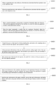
- FIG. 2 is an optional flow chart of a control method of the atomized drug delivery system according to an embodiment of the present application, and the method in FIG. 2 comprises, but is not limited to step S1001 to step S1005.
- step S1001 the respiratory signal detected by the respiratory sensor located on the first ventilation pipeline is acquired.
- step S1002 the respiratory state is determined through the respiratory signal.
- control method of the atomized drug delivery system may be applied to the atomized drug delivery system.
- the atomized drug delivery system does not comprise the ventilator 110, and the ventilators 110 with different functions may be externally connected to the atomized drug delivery system according to specific conditions of different patients, to perform targeted atomized drug delivery according to the conditions of different patients.
- the atomized drug delivery system comprises the ventilator 110, and the ventilator 110 is matched with the atomizer 130 in the atomized drug delivery system, and has a specific adjustable respiratory rate range.
- the ventilator 110 cannot be replaced, so that unification between the ventilator 110 and the atomizer 130 is maintained, and when the atomized drug delivery system delivers a drug to the patient, an optimal drug delivery time will not be missed due to mismatching between the atomizer 130 and the newly connected ventilator 110.
- step S1003 when the respiratory state is the inspiratory state, the frequency of the atomizing apparatus in the atomizer is adjusted through the host machine of the atomizer, to control the atomizing apparatus to atomize the stored drug and deliver the atomized drug to the first ventilation pipeline.
- step S1004 when the respiratory state is the expiratory state, the frequency of the atomizing apparatus is adjusted through the host machine, to control the atomizing apparatus to stop atomizing the drug.
- the host machine 131 of the atomizer 130 can control an atomizing frequency of the atomizing apparatus 132 according to the respiratory state detected by the respiratory sensor 120. For example, when the respiratory sensor 120 detects that the respiratory state of the patient is the inspiratory state, the host machine 131 controls the atomizing apparatus 132 to atomize the stored drug, and the atomizing frequency may be adjusted. For example, when the atomized drug delivery system is just started, a relatively high atomizing frequency may be set, and after a gas flow in the system is stable, the atomizing frequency of the atomizer 130 may be reduced.
- the host machine 131 controls the atomizing apparatus 132 to stop atomizing the stored drug.
- the atomizer 130 detects the respiratory state through the respiratory sensor 120, and then adjusts the atomizing frequency according to the respiratory state.
- the ventilator 110 is in the inspiratory state, the patient is in the expiratory state, and the atomizer 130 stops atomizing the drug.
- the ventilator 110 is in the expiratory state, the patient is in the inspiratory state, and the atomizer 130 atomizes the drug, so that the patient can inhale the atomized drug at the moment, thus achieving the purpose of accurate drug delivery.
- step S1005 the exhaled gas is acquired through the spirometer located on the second ventilation pipeline, and the vital capacity parameter is calculated according to the gas.
- the exhaled gas of the patient can reach the spirometer 140 through the second ventilation pipeline 102, and the spirometer 140 can calculate an activity parameter related to lungs according to the exhaled gas of the patient.
- the vital capacity parameter is used for indicating various parameter values of lung function of the current patient who is being delivered with atomized drug by the atomized drug delivery system, and is compared with a normal range to achieve the purpose of real-time detection of the lung function after delivery with atomized drug.
- FIG. 3 is a flow chart of the step S1002 in FIG. 2 , and in some embodiments, the step S1002 may further comprise step S2001 to step S2002.
- step S2001 when a signal direction value indicates a first direction, it is determined that the respiratory state is the expiratory state.
- step S2002 when the signal direction value indicates a second direction, it is determined that the respiratory state is the inspiratory state.
- the first direction is set to be from the ventilator 110 to the atomizer 130
- the second direction is set to be from the atomizer 130 to the ventilator 110.
- the signal direction value is divided into a positive value and a negative value.
- the signal direction value indicates the first direction when the signal direction value is positive, and the respiratory state of the ventilator 110 is the expiratory state, and the respiratory state of the patient is the inspiratory state.
- the signal direction value indicates the second direction when the signal direction value is negative, and the respiratory state of the ventilator 110 is the inspiratory state, and the respiratory state of the patient is the expiratory state.
- FIG. 4 is another optional flow chart of the control method of the atomized drug delivery system according to an embodiment of the present application.
- the respiratory signal comprises a signal magnitude
- a respiratory threshold is set for the system.
- the method in FIG. 4 comprises, but is not limited to step S3001 to step S3002.
- step S3001 when the signal magnitude is greater than the respiratory threshold, the frequency of the atomizing apparatus is adjusted through the host machine, to control the atomizing apparatus to reduce a drug atomization amount.
- step S3002 when the signal magnitude is smaller than the respiratory threshold, the frequency of the atomizing apparatus is adjusted through the host machine, to control the atomizing apparatus to increase the drug atomization amount.
- the respiratory threshold is set for the system. Meanwhile, the respiratory threshold is adjustable, and the respiratory threshold is used for indicating a respiratory weakness degree of the patient.
- the signal magnitude may be a pressure value of one respiration. When the pressure value is greater than the preset respiratory threshold of the system, it is indicated that the patient has a strong spontaneous respiratory ability, and the drug atomization amount of the atomizing apparatus 132 may be reduced. When the pressure value is smaller than the preset respiratory threshold of the system, it is indicated that the patient has a weak spontaneous respiratory ability, and the drug atomization amount of the atomizing apparatus 132 may be increased.
- the signal magnitude may be a respiratory rate over a period of time.
- the respiratory sensor 120 detects that the respiratory rate of the patient is higher than the preset respiratory threshold of the system, it is indicated that the patient may not adapt to the atomized drug, and the drug atomization amount of the atomizing apparatus 132 may be reduced, and meanwhile, the upper computer 180 connected with the atomizer 130 gives an alert prompt.
- the respiratory sensor 120 detects that the respiratory rate of the patient is lower than the preset respiratory threshold of the system, it is indicated that the patient respires weakly, and at the moment, the drug atomization amount of the atomizing apparatus 132 may be increased, to increase a drug amount inhaled by the patient each time.
- FIG. 5 is a flow chart of the step S1005 in FIG. 2 , and in some embodiments, the step S1005 may further comprise step S4001 to step S4003.
- step S4001 the gas is sampled at a high speed to obtain sampling data, and the sampling data are analyzed to obtain a forced vital capacity and a peak flow velocity.
- step S4002 pressure information of the gas is collected, a pressure analog signal value of the gas is obtained according to the pressure information, and a gas capacity of the gas is calculated according to the pressure analog signal value.
- step S4003 at least one of the forced vital capacity, the peak flow velocity or the gas capacity is taken as the vital capacity parameter.
- the spirometer 140 can sample the exhaled gas of the patient at a high speed to obtain the sampling data, and analyze the sampling data to obtain the forced vital capacity, the peak flow velocity and other vital capacity parameters, wherein the forced vital capacity refers to a maximum amount of gas that can be exhaled as soon as possible after trying to inspire gas as much as possible, which is a primary indicator to judge a lung expansion ability; and the peak flow velocity refers to a maximum instantaneous flow velocity during measuring the forced vital capacity, which mainly reflects a strength of respiratory muscles and whether an air passage is blocked or not.
- the spirometer 140 obtains various vital capacity parameters from the exhaled gas of the patient, which realizes real-time detection of the lung function of the patient subjected to atomized drug delivery when the atomized drug delivery system performs the atomized drug delivery to the patient, to feed back an atomized drug delivery effect.
- a pressure sensor is arranged in the spirometer 140.
- the pressure sensor can collect pressure information of the exhaled gas of the patient, convert the pressure information into a corresponding pressure analog signal value, and finally calculate a gas capacity of the exhaled gas of the patient, which is used for evaluating whether the respiration of the patient is normal or not.
- the forced vital capacity, the peak flow velocity and the gas capacity may all be used as lung activity parameters in lung function detection of the patient, and one of the parameters may be selected as the most important reference parameter according to actual needs, or the lung activity parameters may be given weights, to comprehensively judge the atomized drug delivery condition and the respiratory condition of the patient through the vital capacity parameter.
- FIG. 6 is yet another optional flow chart of the control method of the atomized drug delivery system according to an embodiment of the present application, and in some optional embodiments, the system further comprises the upper computer, and the upper computer is connected with the ventilator, the atomizer and the spirometer.
- the method in FIG. 6 comprises, but is not limited to step S5001 to step S5002.
- step S5001 the test instruction is sent to the ventilator, the atomizer or the spirometer through the test module of the upper computer, so that the ventilator, the atomizer and/or the spirometer is capable of generating the reply information according to the test instruction.
- step S5002 the reply information is sent to the upper computer, the reply information is processed, and the display information and graph obtained by processing are displayed through the display module of the upper computer.
- control method of the atomized drug delivery system may be executed in the atomized drug delivery system, which means that the upper computer in the control method of the atomized drug delivery system and the atomized drug delivery system of the embodiment shown in FIG 1 both belong to the same inventive concept, so that these embodiments have the same realization principle and technical effect, which will not be described in detail herein.
- At least one (item) and “several” refer to being one or more, and “multiple” refers to being two or more.
- “And/or” is used for describing the relationship between related objects, and indicates that there may be three relationships. For example, “A and/or B” may indicate that: A exists alone, B exists alone, and A and B both exist, wherein A and B may be singular or plural. The symbol “/” generally indicates that there is a relationship of "or” between the related objects. "At least one (item) of the followings” or similar expression thereof refers to any combination of these items, comprising a singular (item) or any combination of plural (items).
- At least one (item) of a, b or c may indicate: a, b, c, "a and b", “a and c", “b and c", or "a and b and c", wherein a, b and c may be singular or plural.
- the disclosed system and method may be implemented in other ways.
- the system embodiments described above are only illustrative.
- the division of the units above is only a logical function division. In practice, there may be other division methods.
- multiple units or components may be combined or integrated into another system, or some features may be ignored or not executed.
- the illustrated or discussed mutual coupling or direct coupling or communication connection may be indirect coupling or communication connection through some interfaces, apparatuses or units, and may be in electrical, mechanical or other forms.
Landscapes
- Health & Medical Sciences (AREA)
- Life Sciences & Earth Sciences (AREA)
- Engineering & Computer Science (AREA)
- Pulmonology (AREA)
- Veterinary Medicine (AREA)
- Animal Behavior & Ethology (AREA)
- Public Health (AREA)
- General Health & Medical Sciences (AREA)
- Heart & Thoracic Surgery (AREA)
- Biomedical Technology (AREA)
- Hematology (AREA)
- Anesthesiology (AREA)
- Emergency Medicine (AREA)
- Bioinformatics & Cheminformatics (AREA)
- Molecular Biology (AREA)
- Physics & Mathematics (AREA)
- Biophysics (AREA)
- Physiology (AREA)
- Surgery (AREA)
- Medical Informatics (AREA)
- Pathology (AREA)
- Obesity (AREA)
- Measurement Of The Respiration, Hearing Ability, Form, And Blood Characteristics Of Living Organisms (AREA)
- Measuring And Recording Apparatus For Diagnosis (AREA)
- Nitrogen Condensed Heterocyclic Rings (AREA)
Description
- The present application relates to the field of medical devices, and particularly to an atomized drug delivery system and a control method thereof.
- At present, ventilators have been widely used in the medical field. The ventilators are medical devices that can replace spontaneous ventilation function, which are mostly used in patients with respiratory failure, anesthesia respiratory management during surgery, respiratory supportive treatment and emergency resuscitation, and can prevent and treat respiratory failure, reduce complications and save patients' lives. Generally, the ventilator is used in conjunction with an atomizer for atomizing a drug into tiny particles, which are then inhaled by the patient through respiration, reaching the respiratory tract and lungs, thereby achieving painless, rapid, and effective treatment.
-
WO2022/231134A1 discloses a drug aerosol supply apparatus for a respirator comprises: an air purifier discharging first air; an inhaled air sensor for generating a sensing signal by sensing the first air; a heating and humidifying apparatus discharging second air which is formed by adjusting the temperature and the humidity of the first air; a drug fine particle generator operating only when the sensing signal is input, to spray a drug in a fine particle state to the second air; a Y-tube having one end connected to a T-tube and another end connected to a mask or a mouthpiece; and a return tube having one end connected to the Y-tube and another end connected to the air purifier to allow exhaled air to flow. -
US2022/293262A1 discloses a context sensitive guidance (CSG) system for providing clinical interventions to a patient in an emergency medical event includes a CSG engine, patient interface devices configured to generate signals indicative of patient physiologic data, and a display device configured to provide a CSG user interface and medical device(s) configured to couple to the patient interface devices, the CSG engine and the display device, receive the signals, generate the physiologic data from the signals, and send the physiologic data to the CSG engine and the display device, wherein the CSG engine is configured to receive and evaluate the physiologic data, identify a clinical intervention, and send an output based on the clinical intervention to the medical device(s) configured to perform at least one operation in response to the sent output. -
US2012/136269A1 discloses a liquid separation apparatus for removing a liquid from a respiratory gas is provided. The liquid separation apparatus comprises a housing that comprises an input, wherein a sample withdrawn from the respiratory gas is delivered through the input; a first output wherein at least part of the sample of the respiratory gas is discharged through the first output; and a first filter configured to remove the liquid from the sample of respiratory gas flowing through the input and the first output of the housing. The first filter comprises a hydrophobic property and an oleophobic property to remove the liquid when a surface tension of the liquid is lower than a surface tension of bodily fluids. -
US4787655A discloses an airtight connection for breathing circuits. The invention comprises a swivel adapter for a ventilator breathing system serving an incapacitated patient. The swivel adapter utilizes a pair of corrugated hoses which mate with a pair of arms which are permitted to swivel on the body of the adapter. A ribbed collar is disposed on the body of the adapter and receives an endotracheal tube inserted within the trachea of the patient. A locking means secures the branches of the body to the swivelable arms of the adapter, and a circumferential sealing means, in the form of an 'o'-ring is disposed between the branch and its receiving orifice in its respective arm, to permit secure swiveling thereof, while preventing leakage of any gases therefrom. -
US5964219A discloses a method and an arrangement for processing respiratory gas of an intubated patient, wherein the level of humidity of the inhalation gas is increased, if necessary, before the gas is supplied to the patient. To provide accurate and correctly timed humidification, the patient's respiratory volume is measured, the amount of water discharged from the patient is determined on the basis of the measured respiratory volume, and a desired amount of water, dependent on the amount of water discharged from the patient, is supplied to the patient's respiratory tract during the next respiratory phase(s). -
CN213609045U discloses a multi-functional flexible and portable atomization device, wherein it includes a host, a carrying frame mounted on the host for fixing the host, a Y-type multi-functional data cable electrically connected to the host, and an atomizer and a connector respectively arranged on the bifurcated end of the Y-type data cable. - In the related art, the atomizer is generally set to the same respiratory rate as the ventilator connected therewith to perform an atomizing operation. However, this operation is very prone to a non-synchronous phenomenon of atomization and respiration, which is very dangerous for patients and difficult to realize accurate drug delivery, and a related atomized drug delivery system cannot detect a parameter of exhaled gas from lungs.
- The invention relates to an atomized drug delivery system according to the claims.
- In some embodiments, the system further comprises a three-way pipe, the three-way pipe is provided with a first interface, a second interface and a third interface, the first interface is connected with the first ventilation pipeline, the second interface is connected with the second ventilation pipeline, and the third interface is connected with the face mask.
- In some embodiments, the system further comprises a filter, one end of the filter is connected with the ventilator, the other end of the filter is connected with the first ventilation pipeline, and the filter is configured for filtering bacteria and impurities.
- In some embodiments, the system further comprises a humidifier, one end of the humidifier is connected with the filter, the other end of the humidifier is connected with the first ventilation pipeline, the humidifier comprises a humidity assembly and a heating assembly, the humidity assembly is configured for adjusting humidity of exhaled gas of the ventilator, and the heating assembly is configured for adjusting temperature of the gas.
- In some embodiments, the system further comprises an upper computer, the upper computer is connected with the ventilator, the atomizer and the spirometer, the upper computer comprises a test module and a display module, the test module is configured for sending a test instruction to the ventilator, the atomizer and/or the spirometer, so that the ventilator, the atomizer and/or the spirometer is capable of generating reply information according to the test instruction, and the display module is configured for displaying display information and graph obtained by processing the reply information.
- Also disclosed is a control method of the atomized drug delivery system described, wherein the control method comprises: acquiring the respiratory signal detected by the respiratory sensor located on the first ventilation pipeline; determining the respiratory state through the respiratory signal; when the respiratory state is the inspiratory state, adjusting the frequency of the atomizing apparatus in the atomizer through the host machine of the atomizer, to control the atomizing apparatus to atomize the stored drug and deliver the atomized drug to the first ventilation pipeline; when the respiratory state is the expiratory state, adjusting the frequency of the atomizing apparatus through the host machine, to control the atomizing apparatus to stop atomizing the drug; and acquiring the exhaled gas through the spirometer located on the second ventilation pipeline, and calculating the vital capacity parameter according to the gas.
- In some embodiments, the respiratory signal comprises a signal direction value, and the determining the respiratory state through the respiratory signal comprises: when the signal direction value indicates a first direction, determining that the respiratory state is the expiratory state; and when the signal direction value indicates a second direction, determining that the respiratory state is the inspiratory state.
- In some embodiments, the respiratory signal comprises a signal magnitude, a respiratory threshold is set for the system, and the control method further comprises: when the signal magnitude is greater than the respiratory threshold, adjusting the frequency of the atomizing apparatus through the host machine, to control the atomizing apparatus to reduce a drug atomization amount; and when the signal magnitude is smaller than the respiratory threshold, adjusting the frequency of the atomizing apparatus through the host machine, to control the atomizing apparatus to increase the drug atomization amount.
- In some embodiments, the calculating the vital capacity parameter according to the gas, comprises: sampling the gas at a high speed to obtain sampling data, and analyzing the sampling data to obtain a forced vital capacity and a peak flow velocity; collecting pressure information of the gas, obtaining a pressure analog signal value of the gas according to the pressure information, and calculating a gas capacity of the gas according to the pressure analog signal value; and taking at least one of the forced vital capacity, the peak flow velocity or the gas capacity as the vital capacity parameter.
- In some embodiments, the system further comprises the upper computer, and the upper computer is connected with the ventilator, the atomizer and the spirometer; and the control method further comprises: sending the test instruction to the ventilator, the atomizer and/or the spirometer through the test module of the upper computer, so that the ventilator, the atomizer and/or the spirometer generates the reply information according to the test instruction; and sending the reply information to the upper computer, processing the reply information, and displaying the display information and graph obtained by processing through the display module of the upper computer.
- The embodiments of the present application provides the atomized drug delivery system and the control method thereof. The respiratory state is determined by acquiring the respiratory signal detected by the respiratory sensor located on the first ventilation pipeline, then the frequency of the atomizing apparatus in the atomizer is adjusted according to the respiratory state, to control the atomizing apparatus to atomize or stop atomizing the stored drug, the exhaled gas is acquired by the spirometer located on the second ventilation pipeline, and the vital capacity parameter is calculated according to the exhaled gas.
- According to the embodiments of the present application, the respiratory state can be detected by the respiratory sensor, the atomizing frequency of the atomizer is adjusted according to this state, and the vital capacity parameter is calculated according to the exhaled gas during atomized drug delivery, to detect a lung function of a patient under the atomized drug delivery system, so that a parameter related to exhaled gas from lungs can be detected in real time while realizing accurate drug delivery under the cooperation between the atomizer and the ventilator.
-
-
FIG. 1 is a schematic diagram of an atomized drug delivery system according to an embodiment of the present application; -
FIG. 2 is an optional flow chart of a control method of the atomized drug delivery system according to an embodiment of the present application; -
FIG. 3 is a flow chart of step S1002 inFIG. 2 ; -
FIG. 4 is another optional flow chart of the control method of the atomized drug delivery system according to an embodiment of the present application; -
FIG. 5 is a flow chart of step S1005 inFIG. 2 ; and -
FIG. 6 is yet another optional flow chart of the control method of the atomized drug delivery system according to an embodiment of the present application. - 100 refers to face mask, 101 refers to first ventilation pipeline, 102 refers to second ventilation pipeline, 110 refers to ventilator, 120 refers to respiratory sensor, 130 refers to atomizer, 131 refers to host machine, 132 refers to atomizing apparatus, 140 refers to spirometer, 150 refers to three-way pipe, 160 refers to filter, 170 refers to humidifier, and 180 refers to upper computer.
- To make the objects, the technical solutions, and the advantages of the present application clearer, the present application is further described in detail hereinafter with reference to the drawings and embodiments. It should be understood that the specific embodiments described herein are only used for explaining the present application and are not intended to limit the present application.
- It should be noted that although the functional module division is performed in the schematic diagram of the apparatus and the logical sequence is shown in the flow chart, in some cases, it is possible to use different module divisions than those in the apparatus or to execute the steps in a different sequence than shown or described in the flowchart.
- Unless otherwise defined, all technical and scientific terms used herein have the same meanings as those commonly understood by those skilled in the art. The terms used herein are only for the purpose of describing the embodiments of the present application, and are not intended to limit the present application.
- Atomized drug delivery is a common medical means, and refers to dispersing a drug into tiny droplets or particles by an atomizing apparatus, to make the tiny droplets or particles suspend in gas and enter respiratory tract and lungs, thus achieving the purpose of humidifying an air passage and relieving respiratory tract inflammation.
- The atomized drug delivery can well relieve respiratory tract infection, atomized drug can directly reach throat, trachea, bronchi and even lungs, and it is more beneficial for coming into play and reducing side effects caused by drug delivery due to a higher local drug concentration.
- Under normal circumstances, an atomizer may be used in conjunction with a ventilator, but in the related art, the atomizer is generally set to the same respiratory rate as the ventilator to perform an atomizing operation, which easily leads to a non-synchronous phenomenon of atomization and respiration, thus being very dangerous for a patient. In addition, the related atomized drug delivery system cannot detect a parameter related to exhaled gas from lungs of the patient.
- On this basis, embodiments of the present application provide an atomized drug delivery system and a control method thereof, through which a parameter of exhaled gas from lungs can be detected while improving the accuracy of atomized drug delivery.
- The atomized drug delivery system and the control method thereof in the embodiments of the present application may be illustrated by the following embodiments.
- It should be noted that, in various embodiments of the present application, when related processing needs to be performed based on user's information, user's behavior data, user's historical data, user's position information and other data related to user's identity or characteristics, user's permission or consent will be obtained first. For example, the user's permission or consent will be obtained first when an access request for user's stored data and user's cache data is acquired. Moreover, the collection, use and processing of these data will comply with the relevant laws, regulations and standards of relevant countries and regions. In addition, when the embodiments of the present application need to acquire user's sensitive personal information, user's separate permission or consent will be obtained by a pop-up window, jumping to a confirmation page, or other modes, and after the user's separate permission or consent is explicitly obtained, necessary user-related data for normal operation of the embodiments of the present application will be acquired.
- The embodiments of the present application is further described hereinafter with reference to
FIG. 1 to FIG. 6 , wherein reference numerals are all mentioned inFIG. 1 to FIG. 6 . - The atomized drug delivery system and the control method thereof according to embodiments of the present application are described in detail hereinafter with reference to the following embodiments, and the atomized drug delivery system in the embodiments of the present application will be described first.
- With reference to
FIG. 1, FIG. 1 is a schematic diagram of an atomized drug delivery system according to an embodiment of the present application, and the system comprises: - a face mask, wherein the face mask is connected with a first ventilation pipeline and a second ventilation pipeline respectively, the first ventilation pipeline is configured for being connected with a ventilator, a respiratory sensor is arranged in the first ventilation pipeline, and the respiratory sensor is configured for detecting a respiratory signal;
- an atomizer, wherein the atomizer is provided with a host machine and an atomizing apparatus, the host machine is connected with the atomizing apparatus and the respiratory sensor, the host machine is configured for receiving the respiratory signal detected by the respiratory sensor, and the atomizing apparatus is further connected with the first ventilation pipeline; wherein, the host machine is configured for determining a respiratory state through the respiratory signal, when the respiratory state is an inspiratory state, the host machine is configured for adjusting a frequency of the atomizing apparatus, to control the atomizing apparatus to atomize a stored drug and deliver the atomized drug to the first ventilation pipeline, and when the respiratory state is an expiratory state, the host machine is configured for adjusting the frequency of the atomizing apparatus through the host machine, to control the atomizing apparatus to stop atomizing the drug; and
- a spirometer, wherein the spirometer is connected with the second ventilation pipeline, and the spirometer is configured for acquiring exhaled gas through the second ventilation pipeline and calculating a vital capacity parameter according to the gas.
- In some embodiments, as shown in
FIG. 1 , a patient may be connected with the atomized drug delivery system through theface mask 100, theface mask 100 is connected with theventilator 110 and theatomizer 130 through thefirst ventilation pipeline 101, and when theatomizer 130 performs atomized drug delivery, the atomized drug may reach theface mask 100 along with exhaled gas of theventilator 110 through thefirst ventilation pipeline 101, so that the patient can inhale the drug through theface mask 100. - In some embodiments, the respiratory state refers to the expiratory state and the inspiratory state of the patient. It can be understood that, when the patient is in the inspiratory state, the ventilator is in the expiratory state, and at the moment, the host machine of the atomizer controls the atomizing apparatus to atomize the drug. When the patient is in the expiratory state, the ventilator is in the inspiratory state, and at the moment, the host machine of the atomizer controls the atomizing apparatus to stop atomizing the drug.
- In some embodiments, the drug to be atomized may be placed in a drug reservoir, and there are many types of drug reservoirs, such as being box-shaped, bottle-shaped, or bag-shaped. The drug reservoir specifically needs to be selected according to drug characteristics of different drugs.
- In some embodiments, the
respiratory sensor 120 may be a gas flow sensor, and the gas flow sensor is a sensor capable of displaying instantaneous flow rate and direction. In the embodiment of the present application, the gas flow sensor may judge the respiratory state according to a direction of gas. For example, when the gas flow sensor detects that the gas of theventilator 110 flows from theventilator 110 towards theatomizer 130, it is indicated that theventilator 110 is in the expiratory state and the patient is in the inspiratory state, and at the moment, theatomizer 130 atomizes the drug. When the gas flow sensor detects that the gas of theventilator 110 flows from theatomizer 130 towards theventilator 110, it is indicated that theventilator 110 is in the inspiratory state and the patient is in the expiratory state, and at the moment, theatomizer 130 stops atomizing the drug. - In some embodiments, the
respiratory sensor 120 may be a pressure sensor, and the gas pressure sensor is a sensor capable of measuring a pressure of gas. In the embodiment of the present application, the gas pressure sensor may judge the respiratory state according to positive or negative value of the pressure of gas. For example, when the gas pressure sensor reads that a pressure value of gas in the system is positive, it is indicated that there is a positive pressure in the system, at the moment, theventilator 110 is in the expiratory state and the patient is in the inspiratory state, and theatomizer 130 atomizes the drug. When the gas pressure sensor reads that the pressure value of the gas in the system is negative, it is indicated that there is a negative pressure in the system, at the moment, theventilator 110 is in the inspiratory state and the patient is in the expiratory state, and theatomizer 130 stops atomizing operation. - That is, the atomizing state of the
atomizer 130 is relevant to the respiratory state detected by therespiratory sensor 120, and theatomizer 130 can perform the atomizing operation according to the respiratory state, thus realizing frequency synchronization between theatomizer 130 and theventilator 110. - It should be noted that the
respiratory sensor 120 may also be other sensors capable of judging the respiratory state, and the above embodiments are only preferred embodiments of the present application, which are not limited herein. - In some embodiments, the
spirometer 140 is connected with theface mask 100 through thesecond ventilation pipeline 102. When the patient exhales, the exhaled gas can flow through thespirometer 140 through thesecond ventilation pipeline 102. At the moment, thespirometer 140 detects a parameter related to the exhaled gas of the patient, to show the effect after delivery with atomized drug. - In some optional embodiments, the atomized drug delivery system further comprises a three-way pipe, the three-way pipe is provided with a first interface, a second interface and a third interface, the first interface is connected with the first ventilation pipeline, the second interface is connected with the second ventilation pipeline, and the third interface is connected with the face mask.
- In some embodiments, the three-
way pipe 150 is mainly configured for changing a flow direction of gas. On one hand, the three-way pipe 150 enables the atomized drug to be delivered to the patient through the third interface connected with theface mask 100, and on the other hand, the exhaled gas can be delivered to thespirometer 140 through the second interface, to detect a parameter related to lung function. - In some optional embodiments, the atomized drug delivery system further comprises a filter, one end of the filter is connected with the ventilator, the other end of the filter is connected with the first ventilation pipeline, and the filter is configured for filtering bacteria and impurities.
- In some embodiments, because the patient's respiratory tract is fragile, bacteria or fine impurities contained in the exhaled gas of the
ventilator 110 may easily cause cross-infection between the patients, leading to the aggravation of disease. In the embodiment of the present application, a gas exhaling end of theventilator 110 is connected with thefilter 160 to filter pollutants such as bacteria and impurities in the gas. - It should be noted that the
filter 160 may be disposable or reusable, which is not specifically limited in the present application. - In some optional embodiments, the atomized drug delivery system further comprises a humidifier, one end of the humidifier is connected with the filter, the other end of the humidifier is connected with the first ventilation pipeline, the humidifier comprises a humidity assembly and a heating assembly, the humidity assembly is configured for adjusting humidity of the exhaled gas of the ventilator, and the heating assembly is configured for adjusting temperature of the gas.
- In some embodiments, the
humidifier 170 comprises the humidity assembly, the humidity assembly can evaporate pure water added into thehumidifier 170, to change liquid water into steam water, and increase the humidity of the exhaled gas of theventilator 110, thus reducing irritation of dry gas to the patient's nasal cavity and respiratory tract. - In some embodiments, the
humidifier 170 comprises the heating assembly, the heating assembly can heat the evaporated gas, so that temperature of the heated gas is maintained in a constant range for the comfort of the patient, thus reducing irritation of low-temperature gas to the patient's nasal cavity and respiratory tract. - In some optional embodiments, the atomized drug delivery system further comprises an upper computer, the upper computer is connected with the ventilator, the atomizer and the spirometer, the upper computer comprises a test module and a display module, the test module is configured for sending a test instruction to the ventilator, the atomizer or the spirometer, so that the ventilator, the atomizer or the spirometer is capable of generating reply information according to the test instruction, and the display module is configured for displaying display information and graph obtained by processing the reply information.
- In some embodiments, the
upper computer 180 is connected with theventilator 110, theatomizer 130 and thespirometer 140, and theupper computer 180 is configured for sending the test instruction to theventilator 110, theatomizer 130 and/or thespirometer 140 and displaying related test results. In addition, theupper computer 180 may also monitor operation conditions of theventilator 110, theatomizer 130 and thespirometer 140. - Further, the test module of the
upper computer 180 can send the test instruction to theventilator 110, and the test instruction comprises a respiratory rate parameter and a respiratory intensity parameter related to operation of theventilator 110. Theventilator 110 responds to the test instruction sent by theupper computer 180 and generates the reply information of theventilator 110, and the reply information of theventilator 110 comprises a parameter value for actual operation of theventilator 110 under the test instruction. The reply information of theventilator 110 is transmitted to theupper computer 180 through a serial port, and theupper computer 180 can generate the display information and graph after processing the reply information of theventilator 110 and display the display information and graph through the display module. - Further, the test module of the
upper computer 180 can send the test instruction to theatomizer 130, and the test instruction comprises an atomizing intensity parameter related to operation of theatomizer 130. Theatomizer 130 responds to the test instruction sent by theupper computer 180 and generates the reply information of theatomizer 130, and the reply information of theatomizer 130 comprises a parameter value for actual operation of theatomizer 130 under the test instruction. The reply information of theatomizer 130 is transmitted to theupper computer 180 through a serial port, and theupper computer 180 can generate the display information and graph after processing the reply information of theatomizer 130 and display the display information and graph through the display module. - Further, the test module of the
upper computer 180 can send the test instruction to thespirometer 140, and the test instruction comprises a lung function test parameter related to operation of thespirometer 140. Thespirometer 140 can respond to the test instruction sent by theupper computer 180 and generates the reply information of thespirometer 140, and the reply information of thespirometer 140 comprises a parameter value for actual operation of thespirometer 140 under the test instruction. The reply information of thespirometer 140 is transmitted to theupper computer 180 through a serial port, and theupper computer 180 can generate the display information and graph after processing the reply information of thespirometer 140 and display the display information and graph through the display module. - Further, the
upper computer 180 may monitor theventilator 110, theatomizer 130 and thespirometer 140 in real time. If any abnormality occurs with theventilator 110, theatomizer 130, orspirometer 140, such as data anomalies or excessive machine temperature, thehost computer 180 can issue an alert. - With reference to
FIG. 2, FIG. 2 is an optional flow chart of a control method of the atomized drug delivery system according to an embodiment of the present application, and the method inFIG. 2 comprises, but is not limited to step S1001 to step S1005. - In step S1001, the respiratory signal detected by the respiratory sensor located on the first ventilation pipeline is acquired.
- In step S1002, the respiratory state is determined through the respiratory signal.
- In some embodiments, the control method of the atomized drug delivery system may be applied to the atomized drug delivery system.
- In some embodiments, the atomized drug delivery system does not comprise the
ventilator 110, and theventilators 110 with different functions may be externally connected to the atomized drug delivery system according to specific conditions of different patients, to perform targeted atomized drug delivery according to the conditions of different patients. - In some embodiments, the atomized drug delivery system comprises the
ventilator 110, and theventilator 110 is matched with theatomizer 130 in the atomized drug delivery system, and has a specific adjustable respiratory rate range. When a patient uses the atomized drug delivery system, theventilator 110 cannot be replaced, so that unification between theventilator 110 and theatomizer 130 is maintained, and when the atomized drug delivery system delivers a drug to the patient, an optimal drug delivery time will not be missed due to mismatching between theatomizer 130 and the newly connectedventilator 110. - In step S1003, when the respiratory state is the inspiratory state, the frequency of the atomizing apparatus in the atomizer is adjusted through the host machine of the atomizer, to control the atomizing apparatus to atomize the stored drug and deliver the atomized drug to the first ventilation pipeline.
- In step S1004, when the respiratory state is the expiratory state, the frequency of the atomizing apparatus is adjusted through the host machine, to control the atomizing apparatus to stop atomizing the drug.
- In some embodiments, the
host machine 131 of theatomizer 130 can control an atomizing frequency of theatomizing apparatus 132 according to the respiratory state detected by therespiratory sensor 120. For example, when therespiratory sensor 120 detects that the respiratory state of the patient is the inspiratory state, thehost machine 131 controls theatomizing apparatus 132 to atomize the stored drug, and the atomizing frequency may be adjusted. For example, when the atomized drug delivery system is just started, a relatively high atomizing frequency may be set, and after a gas flow in the system is stable, the atomizing frequency of theatomizer 130 may be reduced. When therespiratory sensor 120 detects that the respiratory state of the patient is the expiratory state, thehost machine 131 controls theatomizing apparatus 132 to stop atomizing the stored drug. Theatomizer 130 detects the respiratory state through therespiratory sensor 120, and then adjusts the atomizing frequency according to the respiratory state. When theventilator 110 is in the inspiratory state, the patient is in the expiratory state, and theatomizer 130 stops atomizing the drug. When theventilator 110 is in the expiratory state, the patient is in the inspiratory state, and theatomizer 130 atomizes the drug, so that the patient can inhale the atomized drug at the moment, thus achieving the purpose of accurate drug delivery. - In step S1005, the exhaled gas is acquired through the spirometer located on the second ventilation pipeline, and the vital capacity parameter is calculated according to the gas.
- In some embodiments, the exhaled gas of the patient can reach the
spirometer 140 through thesecond ventilation pipeline 102, and thespirometer 140 can calculate an activity parameter related to lungs according to the exhaled gas of the patient. The vital capacity parameter is used for indicating various parameter values of lung function of the current patient who is being delivered with atomized drug by the atomized drug delivery system, and is compared with a normal range to achieve the purpose of real-time detection of the lung function after delivery with atomized drug. - With reference to
FIG. 3, FIG. 3 is a flow chart of the step S1002 inFIG. 2 , and in some embodiments, the step S1002 may further comprise step S2001 to step S2002. - In step S2001, when a signal direction value indicates a first direction, it is determined that the respiratory state is the expiratory state.
- In step S2002, when the signal direction value indicates a second direction, it is determined that the respiratory state is the inspiratory state.
- In some embodiments, the first direction is set to be from the
ventilator 110 to theatomizer 130, and the second direction is set to be from theatomizer 130 to theventilator 110. - Alternatively, the signal direction value is divided into a positive value and a negative value. The signal direction value indicates the first direction when the signal direction value is positive, and the respiratory state of the
ventilator 110 is the expiratory state, and the respiratory state of the patient is the inspiratory state. The signal direction value indicates the second direction when the signal direction value is negative, and the respiratory state of theventilator 110 is the inspiratory state, and the respiratory state of the patient is the expiratory state. - With reference to
FIG. 4, FIG. 4 is another optional flow chart of the control method of the atomized drug delivery system according to an embodiment of the present application. In some embodiments, the respiratory signal comprises a signal magnitude, and a respiratory threshold is set for the system. The method inFIG. 4 comprises, but is not limited to step S3001 to step S3002. - In step S3001, when the signal magnitude is greater than the respiratory threshold, the frequency of the atomizing apparatus is adjusted through the host machine, to control the atomizing apparatus to reduce a drug atomization amount.
- In step S3002, when the signal magnitude is smaller than the respiratory threshold, the frequency of the atomizing apparatus is adjusted through the host machine, to control the atomizing apparatus to increase the drug atomization amount.
- In some embodiments, the respiratory threshold is set for the system. Meanwhile, the respiratory threshold is adjustable, and the respiratory threshold is used for indicating a respiratory weakness degree of the patient. The signal magnitude may be a pressure value of one respiration. When the pressure value is greater than the preset respiratory threshold of the system, it is indicated that the patient has a strong spontaneous respiratory ability, and the drug atomization amount of the
atomizing apparatus 132 may be reduced. When the pressure value is smaller than the preset respiratory threshold of the system, it is indicated that the patient has a weak spontaneous respiratory ability, and the drug atomization amount of theatomizing apparatus 132 may be increased. - Alternatively, the signal magnitude may be a respiratory rate over a period of time. When the
respiratory sensor 120 detects that the respiratory rate of the patient is higher than the preset respiratory threshold of the system, it is indicated that the patient may not adapt to the atomized drug, and the drug atomization amount of theatomizing apparatus 132 may be reduced, and meanwhile, theupper computer 180 connected with theatomizer 130 gives an alert prompt. When therespiratory sensor 120 detects that the respiratory rate of the patient is lower than the preset respiratory threshold of the system, it is indicated that the patient respires weakly, and at the moment, the drug atomization amount of theatomizing apparatus 132 may be increased, to increase a drug amount inhaled by the patient each time. - With reference to
FIG. 5, FIG. 5 is a flow chart of the step S1005 inFIG. 2 , and in some embodiments, the step S1005 may further comprise step S4001 to step S4003. - In step S4001, the gas is sampled at a high speed to obtain sampling data, and the sampling data are analyzed to obtain a forced vital capacity and a peak flow velocity.
- In step S4002, pressure information of the gas is collected, a pressure analog signal value of the gas is obtained according to the pressure information, and a gas capacity of the gas is calculated according to the pressure analog signal value.
- In step S4003, at least one of the forced vital capacity, the peak flow velocity or the gas capacity is taken as the vital capacity parameter.
- In some embodiments, the
spirometer 140 can sample the exhaled gas of the patient at a high speed to obtain the sampling data, and analyze the sampling data to obtain the forced vital capacity, the peak flow velocity and other vital capacity parameters, wherein the forced vital capacity refers to a maximum amount of gas that can be exhaled as soon as possible after trying to inspire gas as much as possible, which is a primary indicator to judge a lung expansion ability; and the peak flow velocity refers to a maximum instantaneous flow velocity during measuring the forced vital capacity, which mainly reflects a strength of respiratory muscles and whether an air passage is blocked or not. Thespirometer 140 obtains various vital capacity parameters from the exhaled gas of the patient, which realizes real-time detection of the lung function of the patient subjected to atomized drug delivery when the atomized drug delivery system performs the atomized drug delivery to the patient, to feed back an atomized drug delivery effect. - In some embodiments, a pressure sensor is arranged in the
spirometer 140. When the pressure sensor detects that the patient is in the expiratory state, the pressure sensor can collect pressure information of the exhaled gas of the patient, convert the pressure information into a corresponding pressure analog signal value, and finally calculate a gas capacity of the exhaled gas of the patient, which is used for evaluating whether the respiration of the patient is normal or not. - In some embodiments, the forced vital capacity, the peak flow velocity and the gas capacity may all be used as lung activity parameters in lung function detection of the patient, and one of the parameters may be selected as the most important reference parameter according to actual needs, or the lung activity parameters may be given weights, to comprehensively judge the atomized drug delivery condition and the respiratory condition of the patient through the vital capacity parameter.
- With reference to
FIG. 6, FIG. 6 is yet another optional flow chart of the control method of the atomized drug delivery system according to an embodiment of the present application, and in some optional embodiments, the system further comprises the upper computer, and the upper computer is connected with the ventilator, the atomizer and the spirometer. The method inFIG. 6 comprises, but is not limited to step S5001 to step S5002. - In step S5001, the test instruction is sent to the ventilator, the atomizer or the spirometer through the test module of the upper computer, so that the ventilator, the atomizer and/or the spirometer is capable of generating the reply information according to the test instruction.
- In step S5002, the reply information is sent to the upper computer, the reply information is processed, and the display information and graph obtained by processing are displayed through the display module of the upper computer.
- In some embodiments, the control method of the atomized drug delivery system may be executed in the atomized drug delivery system, which means that the upper computer in the control method of the atomized drug delivery system and the atomized drug delivery system of the embodiment shown in
FIG 1 both belong to the same inventive concept, so that these embodiments have the same realization principle and technical effect, which will not be described in detail herein. - The embodiments of the present application are provided for the purpose of describing the technical solutions of the present application more clearly, and do not constitute the limitation to the technical solutions of the present application. Those of ordinary skills in the art know that, as the technical evolution and the emergence of new application scenarios, the technical solutions of the present application are also applicable to similar technical problems.
- Those of ordinary skills in the art can understand that the technical solutions shown in the drawings does not constitute the limitation to the embodiments of the present application, and may comprise more or less steps than those shown in the drawings, or combine some steps, or comprise different steps.
- The system embodiments described above are only illustrative, wherein the units described as separate components may or may not be physically separated, which means that the units may be located in one place or distributed to multiple network units. Some or all of the modules may be selected according to actual needs to achieve the objects of the solutions in the embodiments.
- Those of ordinary skills in the art can understand that all or some of the steps in the method, and the functional modules/units in the system, the device disclosed above may be implemented as software, firmware, hardware and an appropriate combination thereof.
- The terms "first", "second", "third", "fourth", and the like (if any) in the specification and the drawings of the present application above are used to distinguish similar objects, and are not necessarily used to describe a specific order or sequence. It should be understood that data used in this way may be interchanged under appropriate circumstances, so that the embodiments of the present application described herein can be implemented in a sequence other than those illustrated or described herein. In addition, the terms "comprising", "having" and any variations thereof are intended to cover non-exclusive inclusion. For example, a process, method, system, product or device comprising a series of steps or units is not necessarily limited to those steps or units clearly listed, but may comprise other steps or units not clearly listed in or inherent to the process, method, product or device.
- It should be understood that, in the present application, "at least one (item)" and "several" refer to being one or more, and "multiple" refers to being two or more. "And/or" is used for describing the relationship between related objects, and indicates that there may be three relationships. For example, "A and/or B" may indicate that: A exists alone, B exists alone, and A and B both exist, wherein A and B may be singular or plural. The symbol "/" generally indicates that there is a relationship of "or" between the related objects. "At least one (item) of the followings" or similar expression thereof refers to any combination of these items, comprising a singular (item) or any combination of plural (items). For example, at least one (item) of a, b or c may indicate: a, b, c, "a and b", "a and c", "b and c", or "a and b and c", wherein a, b and c may be singular or plural.
- In the several embodiments provided in the present application, it should be understood that the disclosed system and method may be implemented in other ways. For example, the system embodiments described above are only illustrative. For example, the division of the units above is only a logical function division. In practice, there may be other division methods. For another example, multiple units or components may be combined or integrated into another system, or some features may be ignored or not executed. In addition, the illustrated or discussed mutual coupling or direct coupling or communication connection may be indirect coupling or communication connection through some interfaces, apparatuses or units, and may be in electrical, mechanical or other forms.
- The preferred embodiments of the present application are described above with reference to the drawings, and are not intended to limit the scope of the present application. Any modification, equivalent substitution and improvement made by those of ordinary skills in the art without departing from the scope and essence of the present application should be included within the scope of the present application.
Claims (5)
- An atomized drug delivery system, comprising:a face mask (100), wherein the face mask (100) is connected with a first ventilation pipeline (101) and a second ventilation pipeline (102) respectively, the first ventilation pipeline (101) is connected with a ventilator (110), a respiratory sensor (120) is arranged in the first ventilation pipeline (101), and the respiratory sensor (120) is configured for detecting a respiratory signal;an atomizer (130), wherein the atomizer (130) is provided with a host machine (131) and an atomizing apparatus (132), the host machine (131) is connected with the atomizing apparatus (132) and the respiratory sensor (120), the host machine (131) is configured for receiving the respiratory signal detected by the respiratory sensor (120), and the atomizing apparatus (132) is further connected with the first ventilation pipeline (101); wherein, the host machine (131) is configured for determining a respiratory state through the respiratory signal, when the respiratory state is an inspiratory state, the host machine (131) is configured for adjusting a frequency of the atomizing apparatus (132), to control the atomizing apparatus (132) to atomize a stored drug and deliver the atomized drug to the first ventilation pipeline (101), and when the respiratory state is an expiratory state, the host machine (131) is configured for adjusting the frequency of the atomizing apparatus (132), to control the atomizing apparatus (132) to stop atomizing the drug;characterized in that,the atomized drug delivery system comprises a spirometer (140) that is connected with the second ventilation pipeline (102), wherein the spirometer (140) is configured for acquiring exhaled gas through the second ventilation pipeline (102) and calculating a vital capacity parameter according to the gas, to feed back an atomized drug delivery effect;wherein the host machine is configured to adjust the frequency of the atomizing apparatus to control the atomizing apparatus to reduce a drug atomization amount when a signal magnitude of the respiratory signal is greater than a set respiratory threshold for the system; andwherein the host machine is configured to adjust the frequency of the atomizing apparatus to control the atomizing apparatus to increase a drug atomization amount when a signal magnitude of the respiratory signal is smaller than the set respiratory threshold for the system.
- The atomized drug delivery system according to claim 1, further comprising a three-way pipe (150), wherein the three-way pipe (150) is provided with a first interface, a second interface and a third interface, the first interface is connected with the first ventilation pipeline (101), the second interface is connected with the second ventilation pipeline (102), and the third interface is connected with the face mask (100).
- The atomized drug delivery system according to claim 1, further comprising a filter (160), wherein one end of the filter (160) is connected with the ventilator (110), the other end of the filter (160) is connected with the first ventilation pipeline (101), and the filter (160) is configured for filtering bacteria and impurities.
- The atomized drug delivery system according to claim 3, further comprising a humidifier (170), wherein one end of the humidifier (170) is connected with the filter (160), the other end of the humidifier (170) is connected with the first ventilation pipeline (101), the humidifier (170) comprises a humidity assembly and a heating assembly, the humidity assembly is configured for adjusting humidity of exhaled gas of the ventilator (110), and the heating assembly is configured for adjusting temperature of the gas.
- The atomized drug delivery system according to claim 1, further comprising an upper computer (180), wherein the upper computer (180) is connected with the ventilator (110), the atomizer (130) and the spirometer (140), the upper computer (180) comprises a test module and a display module, the test module is configured for sending a test instruction to the ventilator (110), the atomizer (130) and/or the spirometer (140), so that the ventilator (110), the atomizer (130) and/or the spirometer (140) is capable of generating reply information according to the test instruction, and the display module is configured for displaying display information and graph obtained by processing the reply information.
Applications Claiming Priority (1)
| Application Number | Priority Date | Filing Date | Title |
|---|---|---|---|
| CN202310231740.5A CN116212177A (en) | 2023-02-28 | 2023-02-28 | An atomized drug delivery system and its control method |
Publications (2)
| Publication Number | Publication Date |
|---|---|
| EP4424233A1 EP4424233A1 (en) | 2024-09-04 |
| EP4424233B1 true EP4424233B1 (en) | 2025-04-23 |
Family
ID=86590870
Family Applications (1)
| Application Number | Title | Priority Date | Filing Date |
|---|---|---|---|
| EP23191467.2A Active EP4424233B1 (en) | 2023-02-28 | 2023-08-15 | Atomized drug delivery system |
Country Status (5)
| Country | Link |
|---|---|
| EP (1) | EP4424233B1 (en) |
| CN (1) | CN116212177A (en) |
| ES (1) | ES3028416T3 (en) |
| PL (1) | PL4424233T3 (en) |
| PT (1) | PT4424233T (en) |
Families Citing this family (12)
| Publication number | Priority date | Publication date | Assignee | Title |
|---|---|---|---|---|
| CN117398554A (en) * | 2023-11-13 | 2024-01-16 | 电子科技大学长三角研究院(湖州) | An intelligent drug atomization system based on MEMS sensor chip |
| CN118649318A (en) * | 2024-06-03 | 2024-09-17 | 南京师范大学 | A breath-driven adjustable atomization volume atomizer driving device and method |
| CN118787823B (en) * | 2024-07-02 | 2025-05-16 | 首都医科大学宣武医院 | Atomization real-time treatment effect evaluation system |
| CN118750702B (en) * | 2024-09-05 | 2024-11-15 | 长春中医药大学附属医院(吉林省中医院) | Drug delivery device for respiratory department |
| CN118846310A (en) * | 2024-09-11 | 2024-10-29 | 磐安县人民医院(磐安县人民医院医共体) | An intelligent atomization system for pediatric respiratory tract treatment |
| CN119587812B (en) * | 2024-10-28 | 2025-11-18 | 深圳来福士雾化医学有限公司 | Atomization control methods and systems, electronic devices |
| EP4734122A1 (en) * | 2024-10-28 | 2026-04-29 | Feellife Health Inc. | Nebulization control method and system, and electronic device |
| CN119587814A (en) * | 2024-12-09 | 2025-03-11 | 江苏鱼跃医疗设备股份有限公司 | A kind of atomization control method and system based on ventilator |
| CN119701145A (en) * | 2024-12-17 | 2025-03-28 | 广州红象医疗科技有限公司 | Intelligent drug delivery system and drug delivery method |
| CN119633221B (en) * | 2024-12-27 | 2025-10-21 | 东莞永昇医疗科技有限公司 | Medicine chamber structure and pulse respiratory therapeutic device |
| CN119453992B (en) * | 2025-01-15 | 2025-04-15 | 湖南欧讯医疗科技有限公司 | A detection system |
| CN119453993B (en) * | 2025-01-15 | 2025-05-23 | 湖南欧讯医疗科技有限公司 | Detection system |
Family Cites Families (9)
| Publication number | Priority date | Publication date | Assignee | Title |
|---|---|---|---|---|
| US4787655A (en) * | 1986-04-24 | 1988-11-29 | The Kendall Company | Airtight connection for breathing circuits |
| FI104312B1 (en) * | 1996-06-27 | 1999-12-31 | Instrumentarium Oy | An arrangement for treating the respiratory gas of an intubated patient |
| EP2203155A1 (en) * | 2007-09-25 | 2010-07-07 | Novartis Ag | Treatment of pulmonary disorders with aerosolized medicaments such as vancomycin |
| EP2457506B1 (en) * | 2010-11-26 | 2015-09-02 | General Electric Company | Liquid separation apparatus for removing a liquid from a respiratory gas and respiratory gas analyzing system |
| ES2993168T3 (en) * | 2017-03-23 | 2024-12-23 | Stamford Devices Ltd | Retrofit aerosol delivery system |
| CN110141740A (en) * | 2019-05-20 | 2019-08-20 | 上海交通大学医学院附属新华医院 | A Portable Smart Mesh Nebulizer with Pulmonary Function Testing System |
| CN213609045U (en) * | 2020-07-06 | 2021-07-06 | 深圳来福士雾化医学有限公司 | Multifunctional flexible portable atomization device |
| CN116964680A (en) * | 2021-03-11 | 2023-10-27 | Zoll医疗公司 | Resuscitation care system for context-sensitive guidance |
| KR102364175B1 (en) * | 2021-04-26 | 2022-02-18 | 엔텍메디칼(주) | Drug aerosol supply device for artificial respirator |
-
2023
- 2023-02-28 CN CN202310231740.5A patent/CN116212177A/en active Pending
- 2023-08-15 PL PL23191467.2T patent/PL4424233T3/en unknown
- 2023-08-15 ES ES23191467T patent/ES3028416T3/en active Active
- 2023-08-15 EP EP23191467.2A patent/EP4424233B1/en active Active
- 2023-08-15 PT PT231914672T patent/PT4424233T/en unknown
Also Published As
| Publication number | Publication date |
|---|---|
| PL4424233T3 (en) | 2025-06-16 |
| PT4424233T (en) | 2025-05-22 |
| EP4424233A1 (en) | 2024-09-04 |
| ES3028416T3 (en) | 2025-06-19 |
| CN116212177A (en) | 2023-06-06 |
Similar Documents
| Publication | Publication Date | Title |
|---|---|---|
| EP4424233A1 (en) | Atomized drug delivery system and control method thereof | |
| AU2023203136B2 (en) | Humidification of respiratory gases | |
| US10342456B2 (en) | Apparatus, arrangement and method for analyzing breathing gas flowing along breathing tubing for subject breathing | |
| US20260048218A1 (en) | System and method of detection of water in a conduit for use in a respiratory therapy system | |
| JP3641431B2 (en) | Patient monitoring device and use thereof | |
| CN102302817B (en) | Respirator | |
| US8991393B2 (en) | Monitor for measuring improvement in involuntary breathing | |
| EP2383008B1 (en) | Arrangement for maintaining volume of breathing gas in a desired level | |
| WO2015002661A1 (en) | Method and system for controlling breathing | |
| WO2013026902A1 (en) | Devices and methods for generating an artificial exhalation profile | |
| JPH09234247A (en) | Artificial respiratory apparatus and improved heating/ humidifying device | |
| US10821247B2 (en) | Ventilator and operating method for a ventilator with a determination of cough attacks | |
| US10821246B2 (en) | Medical device and method for determining operating situations in a medical device | |
| CN111643086B (en) | Bilateral nasal resistance and nasal flow testing device and testing method | |
| CN116492553A (en) | Respiration detection system | |
| CN204017086U (en) | No supply and monitoring device and respiratory system | |
| KR102641547B1 (en) | Apparatus for extracting patient's flow ina high flow theraphy device using cannula | |
| CN220276094U (en) | A synchronous atomization control system and respiratory humidification treatment equipment | |
| EP4146309B1 (en) | Apparatus and non-transitory storage medium for estimating inhale dose of a person | |
| EP4129373B1 (en) | Intelligent distribution module for ventilators | |
| US20230191067A1 (en) | Expiratory filter with embedded detectors | |
| CN105879171B (en) | A kind of positive and negative pressure breathing machine | |
| EP4480520A1 (en) | Monitoring system for assisting and monitoring the nebulisation process | |
| French et al. | Effect of ventilation equipment on imposed work of breathing | |
| WO2021242086A1 (en) | Device for automatic and communicating artificial respiration: mechanical ventilator. |
Legal Events
| Date | Code | Title | Description |
|---|---|---|---|
| STAA | Information on the status of an ep patent application or granted ep patent |
Free format text: STATUS: EXAMINATION IS IN PROGRESS |
|
| PUAI | Public reference made under article 153(3) epc to a published international application that has entered the european phase |
Free format text: ORIGINAL CODE: 0009012 |
|
| 17P | Request for examination filed |
Effective date: 20230815 |
|
| AK | Designated contracting states |
Kind code of ref document: A1 Designated state(s): AL AT BE BG CH CY CZ DE DK EE ES FI FR GB GR HR HU IE IS IT LI LT LU LV MC ME MK MT NL NO PL PT RO RS SE SI SK SM TR |
|
| REG | Reference to a national code |
Ref country code: DE Ref legal event code: R079 Free format text: PREVIOUS MAIN CLASS: A61B0005083000 Ipc: A61M0016000000 Ref document number: 602023003060 Country of ref document: DE |
|
| GRAP | Despatch of communication of intention to grant a patent |
Free format text: ORIGINAL CODE: EPIDOSNIGR1 |
|
| STAA | Information on the status of an ep patent application or granted ep patent |
Free format text: STATUS: GRANT OF PATENT IS INTENDED |
|
| RIC1 | Information provided on ipc code assigned before grant |
Ipc: A61M 11/00 20060101ALN20241113BHEP Ipc: A61B 5/083 20060101ALI20241113BHEP Ipc: A61M 16/14 20060101ALI20241113BHEP Ipc: A61M 16/00 20060101AFI20241113BHEP |
|
| INTG | Intention to grant announced |
Effective date: 20241120 |
|
| GRAS | Grant fee paid |
Free format text: ORIGINAL CODE: EPIDOSNIGR3 |
|
| GRAA | (expected) grant |
Free format text: ORIGINAL CODE: 0009210 |
|
| STAA | Information on the status of an ep patent application or granted ep patent |
Free format text: STATUS: THE PATENT HAS BEEN GRANTED |
|
| AK | Designated contracting states |
Kind code of ref document: B1 Designated state(s): AL AT BE BG CH CY CZ DE DK EE ES FI FR GB GR HR HU IE IS IT LI LT LU LV MC ME MK MT NL NO PL PT RO RS SE SI SK SM TR |
|
| P01 | Opt-out of the competence of the unified patent court (upc) registered |
Free format text: CASE NUMBER: APP_12827/2025 Effective date: 20250314 |
|
| REG | Reference to a national code |
Ref country code: GB Ref legal event code: FG4D |
|
| REG | Reference to a national code |
Ref country code: CH Ref legal event code: EP |
|
| REG | Reference to a national code |
Ref country code: DE Ref legal event code: R096 Ref document number: 602023003060 Country of ref document: DE |
|
| REG | Reference to a national code |
Ref country code: IE Ref legal event code: FG4D |
|
| REG | Reference to a national code |
Ref country code: PT Ref legal event code: SC4A Ref document number: 4424233 Country of ref document: PT Date of ref document: 20250522 Kind code of ref document: T Free format text: AVAILABILITY OF NATIONAL TRANSLATION Effective date: 20250519 |
|
| REG | Reference to a national code |
Ref country code: NL Ref legal event code: FP |
|
| REG | Reference to a national code |
Ref country code: ES Ref legal event code: FG2A Ref document number: 3028416 Country of ref document: ES Kind code of ref document: T3 Effective date: 20250619 |
|
| PG25 | Lapsed in a contracting state [announced via postgrant information from national office to epo] |
Ref country code: FI Free format text: LAPSE BECAUSE OF FAILURE TO SUBMIT A TRANSLATION OF THE DESCRIPTION OR TO PAY THE FEE WITHIN THE PRESCRIBED TIME-LIMIT Effective date: 20250423 |
|
| PGFP | Annual fee paid to national office [announced via postgrant information from national office to epo] |
Ref country code: ES Payment date: 20250909 Year of fee payment: 3 Ref country code: PT Payment date: 20250812 Year of fee payment: 3 |
|
| PGFP | Annual fee paid to national office [announced via postgrant information from national office to epo] |
Ref country code: DE Payment date: 20250805 Year of fee payment: 3 |
|
| REG | Reference to a national code |
Ref country code: LT Ref legal event code: MG9D |
|
| PG25 | Lapsed in a contracting state [announced via postgrant information from national office to epo] |
Ref country code: GR Free format text: LAPSE BECAUSE OF FAILURE TO SUBMIT A TRANSLATION OF THE DESCRIPTION OR TO PAY THE FEE WITHIN THE PRESCRIBED TIME-LIMIT Effective date: 20250724 Ref country code: NO Free format text: LAPSE BECAUSE OF FAILURE TO SUBMIT A TRANSLATION OF THE DESCRIPTION OR TO PAY THE FEE WITHIN THE PRESCRIBED TIME-LIMIT Effective date: 20250723 |
|
| PGFP | Annual fee paid to national office [announced via postgrant information from national office to epo] |
Ref country code: PL Payment date: 20250812 Year of fee payment: 3 Ref country code: IT Payment date: 20250901 Year of fee payment: 3 |
|
| PG25 | Lapsed in a contracting state [announced via postgrant information from national office to epo] |
Ref country code: BG Free format text: LAPSE BECAUSE OF FAILURE TO SUBMIT A TRANSLATION OF THE DESCRIPTION OR TO PAY THE FEE WITHIN THE PRESCRIBED TIME-LIMIT Effective date: 20250423 |
|
| PGFP | Annual fee paid to national office [announced via postgrant information from national office to epo] |
Ref country code: BE Payment date: 20250818 Year of fee payment: 3 |
|
| PG25 | Lapsed in a contracting state [announced via postgrant information from national office to epo] |
Ref country code: HR Free format text: LAPSE BECAUSE OF FAILURE TO SUBMIT A TRANSLATION OF THE DESCRIPTION OR TO PAY THE FEE WITHIN THE PRESCRIBED TIME-LIMIT Effective date: 20250423 |
|
| PGFP | Annual fee paid to national office [announced via postgrant information from national office to epo] |
Ref country code: FR Payment date: 20250808 Year of fee payment: 3 Ref country code: AT Payment date: 20251020 Year of fee payment: 3 |
|
| PG25 | Lapsed in a contracting state [announced via postgrant information from national office to epo] |
Ref country code: RS Free format text: LAPSE BECAUSE OF FAILURE TO SUBMIT A TRANSLATION OF THE DESCRIPTION OR TO PAY THE FEE WITHIN THE PRESCRIBED TIME-LIMIT Effective date: 20250723 |
|
| PGFP | Annual fee paid to national office [announced via postgrant information from national office to epo] |
Ref country code: CZ Payment date: 20250813 Year of fee payment: 3 Ref country code: IE Payment date: 20250812 Year of fee payment: 3 |
|
| PG25 | Lapsed in a contracting state [announced via postgrant information from national office to epo] |
Ref country code: IS Free format text: LAPSE BECAUSE OF FAILURE TO SUBMIT A TRANSLATION OF THE DESCRIPTION OR TO PAY THE FEE WITHIN THE PRESCRIBED TIME-LIMIT Effective date: 20250823 |
|
| PG25 | Lapsed in a contracting state [announced via postgrant information from national office to epo] |
Ref country code: LV Free format text: LAPSE BECAUSE OF FAILURE TO SUBMIT A TRANSLATION OF THE DESCRIPTION OR TO PAY THE FEE WITHIN THE PRESCRIBED TIME-LIMIT Effective date: 20250423 |
|
| PG25 | Lapsed in a contracting state [announced via postgrant information from national office to epo] |
Ref country code: SM Free format text: LAPSE BECAUSE OF FAILURE TO SUBMIT A TRANSLATION OF THE DESCRIPTION OR TO PAY THE FEE WITHIN THE PRESCRIBED TIME-LIMIT Effective date: 20250423 Ref country code: DK Free format text: LAPSE BECAUSE OF FAILURE TO SUBMIT A TRANSLATION OF THE DESCRIPTION OR TO PAY THE FEE WITHIN THE PRESCRIBED TIME-LIMIT Effective date: 20250423 |
|
| PG25 | Lapsed in a contracting state [announced via postgrant information from national office to epo] |
Ref country code: EE Free format text: LAPSE BECAUSE OF FAILURE TO SUBMIT A TRANSLATION OF THE DESCRIPTION OR TO PAY THE FEE WITHIN THE PRESCRIBED TIME-LIMIT Effective date: 20250423 |
|
| REG | Reference to a national code |
Ref country code: DE Ref legal event code: R097 Ref document number: 602023003060 Country of ref document: DE |
|
| PG25 | Lapsed in a contracting state [announced via postgrant information from national office to epo] |
Ref country code: SK Free format text: LAPSE BECAUSE OF FAILURE TO SUBMIT A TRANSLATION OF THE DESCRIPTION OR TO PAY THE FEE WITHIN THE PRESCRIBED TIME-LIMIT Effective date: 20250423 |
|
| PLBE | No opposition filed within time limit |
Free format text: ORIGINAL CODE: 0009261 |
|
| STAA | Information on the status of an ep patent application or granted ep patent |
Free format text: STATUS: NO OPPOSITION FILED WITHIN TIME LIMIT |
|
| REG | Reference to a national code |
Ref country code: CH Ref legal event code: L10 Free format text: ST27 STATUS EVENT CODE: U-0-0-L10-L00 (AS PROVIDED BY THE NATIONAL OFFICE) Effective date: 20260304 |
|
| PG25 | Lapsed in a contracting state [announced via postgrant information from national office to epo] |
Ref country code: RO Free format text: LAPSE BECAUSE OF FAILURE TO SUBMIT A TRANSLATION OF THE DESCRIPTION OR TO PAY THE FEE WITHIN THE PRESCRIBED TIME-LIMIT Effective date: 20250423 |
|
| PG25 | Lapsed in a contracting state [announced via postgrant information from national office to epo] |
Ref country code: MC Free format text: LAPSE BECAUSE OF FAILURE TO SUBMIT A TRANSLATION OF THE DESCRIPTION OR TO PAY THE FEE WITHIN THE PRESCRIBED TIME-LIMIT Effective date: 20250423 |
|
| 26N | No opposition filed |
Effective date: 20260126 |
|
| PG25 | Lapsed in a contracting state [announced via postgrant information from national office to epo] |
Ref country code: LU Free format text: LAPSE BECAUSE OF NON-PAYMENT OF DUE FEES Effective date: 20250815 |