EP4424226A1 - Medical endoscope system and operation method thereof - Google Patents
Medical endoscope system and operation method thereof Download PDFInfo
- Publication number
- EP4424226A1 EP4424226A1 EP24159475.3A EP24159475A EP4424226A1 EP 4424226 A1 EP4424226 A1 EP 4424226A1 EP 24159475 A EP24159475 A EP 24159475A EP 4424226 A1 EP4424226 A1 EP 4424226A1
- Authority
- EP
- European Patent Office
- Prior art keywords
- data
- pseudodistance
- actual measurement
- subject
- measurement distance
- Prior art date
- Legal status (The legal status is an assumption and is not a legal conclusion. Google has not performed a legal analysis and makes no representation as to the accuracy of the status listed.)
- Pending
Links
Images

Classifications
-
- A—HUMAN NECESSITIES
- A61—MEDICAL OR VETERINARY SCIENCE; HYGIENE
- A61B—DIAGNOSIS; SURGERY; IDENTIFICATION
- A61B1/00—Instruments for performing medical examinations of the interior of cavities or tubes of the body by visual or photographical inspection, e.g. endoscopes; Illuminating arrangements therefor
- A61B1/00002—Operational features of endoscopes
- A61B1/00004—Operational features of endoscopes characterised by electronic signal processing
- A61B1/00009—Operational features of endoscopes characterised by electronic signal processing of image signals during a use of endoscope
-
- A—HUMAN NECESSITIES
- A61—MEDICAL OR VETERINARY SCIENCE; HYGIENE
- A61B—DIAGNOSIS; SURGERY; IDENTIFICATION
- A61B1/00—Instruments for performing medical examinations of the interior of cavities or tubes of the body by visual or photographical inspection, e.g. endoscopes; Illuminating arrangements therefor
- A61B1/00002—Operational features of endoscopes
- A61B1/00039—Operational features of endoscopes provided with input arrangements for the user
-
- A—HUMAN NECESSITIES
- A61—MEDICAL OR VETERINARY SCIENCE; HYGIENE
- A61B—DIAGNOSIS; SURGERY; IDENTIFICATION
- A61B1/00—Instruments for performing medical examinations of the interior of cavities or tubes of the body by visual or photographical inspection, e.g. endoscopes; Illuminating arrangements therefor
- A61B1/00002—Operational features of endoscopes
- A61B1/00043—Operational features of endoscopes provided with output arrangements
- A61B1/00045—Display arrangement
-
- A—HUMAN NECESSITIES
- A61—MEDICAL OR VETERINARY SCIENCE; HYGIENE
- A61B—DIAGNOSIS; SURGERY; IDENTIFICATION
- A61B1/00—Instruments for performing medical examinations of the interior of cavities or tubes of the body by visual or photographical inspection, e.g. endoscopes; Illuminating arrangements therefor
- A61B1/00163—Optical arrangements
- A61B1/00194—Optical arrangements adapted for three-dimensional imaging
-
- A—HUMAN NECESSITIES
- A61—MEDICAL OR VETERINARY SCIENCE; HYGIENE
- A61B—DIAGNOSIS; SURGERY; IDENTIFICATION
- A61B1/00—Instruments for performing medical examinations of the interior of cavities or tubes of the body by visual or photographical inspection, e.g. endoscopes; Illuminating arrangements therefor
- A61B1/04—Instruments for performing medical examinations of the interior of cavities or tubes of the body by visual or photographical inspection, e.g. endoscopes; Illuminating arrangements therefor combined with photographic or television appliances
- A61B1/05—Instruments for performing medical examinations of the interior of cavities or tubes of the body by visual or photographical inspection, e.g. endoscopes; Illuminating arrangements therefor combined with photographic or television appliances characterised by the image sensor, e.g. camera, being in the distal end portion
-
- A—HUMAN NECESSITIES
- A61—MEDICAL OR VETERINARY SCIENCE; HYGIENE
- A61B—DIAGNOSIS; SURGERY; IDENTIFICATION
- A61B1/00—Instruments for performing medical examinations of the interior of cavities or tubes of the body by visual or photographical inspection, e.g. endoscopes; Illuminating arrangements therefor
- A61B1/06—Instruments for performing medical examinations of the interior of cavities or tubes of the body by visual or photographical inspection, e.g. endoscopes; Illuminating arrangements therefor with illuminating arrangements
- A61B1/0661—Endoscope light sources
-
- A—HUMAN NECESSITIES
- A61—MEDICAL OR VETERINARY SCIENCE; HYGIENE
- A61B—DIAGNOSIS; SURGERY; IDENTIFICATION
- A61B1/00—Instruments for performing medical examinations of the interior of cavities or tubes of the body by visual or photographical inspection, e.g. endoscopes; Illuminating arrangements therefor
- A61B1/273—Instruments for performing medical examinations of the interior of cavities or tubes of the body by visual or photographical inspection, e.g. endoscopes; Illuminating arrangements therefor for the upper alimentary canal, e.g. oesophagoscopes, gastroscopes
- A61B1/2736—Gastroscopes
-
- A—HUMAN NECESSITIES
- A61—MEDICAL OR VETERINARY SCIENCE; HYGIENE
- A61B—DIAGNOSIS; SURGERY; IDENTIFICATION
- A61B5/00—Measuring for diagnostic purposes; Identification of persons
- A61B5/103—Measuring devices for testing the shape, pattern, colour, size or movement of the body or parts thereof, for diagnostic purposes
- A61B5/107—Measuring physical dimensions, e.g. size of the entire body or parts thereof
- A61B5/1076—Measuring physical dimensions, e.g. size of the entire body or parts thereof for measuring dimensions inside body cavities, e.g. using catheters
-
- G—PHYSICS
- G06—COMPUTING OR CALCULATING; COUNTING
- G06T—IMAGE DATA PROCESSING OR GENERATION, IN GENERAL
- G06T7/00—Image analysis
- G06T7/50—Depth or shape recovery
- G06T7/55—Depth or shape recovery from multiple images
- G06T7/579—Depth or shape recovery from multiple images from motion
-
- G—PHYSICS
- G06—COMPUTING OR CALCULATING; COUNTING
- G06V—IMAGE OR VIDEO RECOGNITION OR UNDERSTANDING
- G06V20/00—Scenes; Scene-specific elements
- G06V20/60—Type of objects
- G06V20/64—Three-dimensional [3D] objects
-
- A—HUMAN NECESSITIES
- A61—MEDICAL OR VETERINARY SCIENCE; HYGIENE
- A61B—DIAGNOSIS; SURGERY; IDENTIFICATION
- A61B1/00—Instruments for performing medical examinations of the interior of cavities or tubes of the body by visual or photographical inspection, e.g. endoscopes; Illuminating arrangements therefor
- A61B1/06—Instruments for performing medical examinations of the interior of cavities or tubes of the body by visual or photographical inspection, e.g. endoscopes; Illuminating arrangements therefor with illuminating arrangements
- A61B1/0605—Instruments for performing medical examinations of the interior of cavities or tubes of the body by visual or photographical inspection, e.g. endoscopes; Illuminating arrangements therefor with illuminating arrangements for spatially modulated illumination
-
- G—PHYSICS
- G06—COMPUTING OR CALCULATING; COUNTING
- G06T—IMAGE DATA PROCESSING OR GENERATION, IN GENERAL
- G06T7/00—Image analysis
- G06T7/50—Depth or shape recovery
Definitions
- the present invention relates to a medical endoscope system and an operation method thereof.
- JP2021-189822A discloses an industrial endoscope that constructs a three-dimensional structure model indicating a three-dimensional structure inside a pipe such as a gas pipe using Structure-from-Motion (SfM) and that generates data (pseudodistance data) obtained by estimating a distance to each position (subject) within a captured image using the three-dimensional structure model.
- the pseudodistance data is data obtained by estimating the distance to the subject and thus, may be different from the actual distance.
- the pseudodistance data is corrected using a radius of the pipe based on a fact that the radius of the pipe is constant or can be known in advance.
- JP2021-189822A is based on an assumption that the radius of the pipe is constant or can be known in advance
- the radius of the pipe is not constant or cannot be known in advance in a medical endoscope that images an inside of a body cavity such as a gastrointestinal tract as the subject.
- a medical endoscope that images an inside of a body cavity such as a gastrointestinal tract as the subject.
- the present invention is conceived in view of the above background, and an object thereof is to provide a medical endoscope system and an operation method of a medical endoscope system with which a distance to a subject can be more accurately perceived.
- a medical endoscope system comprises an endoscope including an image sensor that acquires a captured image by imaging an inside of a body cavity as a subject, and a processor, in which the processor is configured to generate pseudodistance data obtained by estimating a distance to the subject for a plurality of locations within an imaging range of the image sensor using the captured image, acquire actual measurement distance data obtained by measuring the distance to the subject for at least one location within the imaging range, and correct the pseudodistance data using the actual measurement distance data.
- the pseudodistance data may be generated using a three-dimensional structure model of the subject that is constructed from captured images of a plurality of frames captured by changing a relative positional relationship between the subject and the image sensor.
- the pseudodistance data may be generated using a distance estimation model that is generated by machine learning using captured images of a plurality of frames captured by changing a relative positional relationship between the subject and the image sensor.
- the actual measurement distance data may be measured using a captured image that is captured by irradiating the subject with auxiliary measurement light of which an optical axis is inclined with respect to an imaging optical axis of the image sensor.
- the auxiliary measurement light may be laser light.
- the subject may be a gastrointestinal tract.
- the processor may be configured to, for the pseudodistance data and the actual measurement distance data of the same location, calculate a scale factor by dividing the actual measurement distance data by the pseudodistance data, and correct pseudodistance data of a location different from the same location by multiplying the pseudodistance data of the different location by the calculated scale factor.
- the processor may be configured to correct pseudodistance data of all locations by multiplying all pieces of the pseudodistance data by the scale factor.
- the processor may be configured to divide the subject into a plurality of regions, and correct pseudodistance data of a region including the same location by multiplying the pseudodistance data within the region including the same location by the scale factor.
- the processor may be configured to, for a region for which the actual measurement distance data is not present, determine a scale factor to be used for correcting the region using a scale factor used for correcting a region for which the actual measurement distance data is present.
- the processor may be configured to correct the region for which the actual measurement distance data is not present using an average value of the scale factors used for correcting the region for which the actual measurement distance data is present as the scale factor.
- the processor may be configured to, for a region for which a plurality of pieces of the actual measurement distance data are present, determine a scale factor to be used for correcting the region using a scale factor of each location for which the actual measurement distance data is present.
- the processor may be configured to correct the region for which the plurality of pieces of actual measurement distance data are present using an average value of the scale factors of each location for which the actual measurement distance data is present as the scale factor.
- any plurality of configurations among the above various configurations may be combined with each other.
- an operation method of a medical endoscope system comprises a pseudodistance data generation step of generating pseudodistance data obtained by estimating a distance to a subject for a plurality of locations within an imaging range of an image sensor of an endoscope using a captured image captured by the image sensor, an actual measurement distance data acquisition step of acquiring actual measurement distance data obtained by measuring the distance to the subject for at least one location within the imaging range, and a distance data correction step of correcting the pseudodistance data using the actual measurement distance data.
- the distance to the subject can be more accurately perceived.
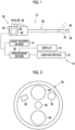
- an endoscope system 10 is a medical endoscope system used for medical purposes and includes an endoscope 12, a light source device 14, a display 16, a user interface 18, and a processor device 20 (processor).
- the endoscope 12 is optically connected to the light source device 14 and is electrically connected to the processor device 20.
- the processor device 20 is electrically connected to each unit (the endoscope 12, the light source device 14, the display 16, and the user interface 18) of the endoscope system 10.
- the endoscope 12 includes, for example, an insertion part 30 inserted into a body cavity such as a gastrointestinal tract, an operating part 32 connected to a proximal end side of the insertion part 30, and a bendable part 34 and a tip part 36 provided on a distal end side of the insertion part 30.
- the operating part 32 is provided with an inlet 38 of a forceps channel for inserting a treatment tool such as forceps.
- the operating part 32 is provided with various operating members that receive operations such as bending of the bendable part 34, zooming during subject imaging, a still image/video image capturing instruction, switching of an imaging mode, air supply, and water supply from a user.
- rotary dials 40, 42, and 44 subjected to a rotation operation and push buttons 46, 48, and 50 subjected to a push operation are provided as the above operating members.
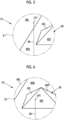
- the tip part 36 is provided with an illumination window 52 for emitting illumination light, an observation window 54 for capturing reflected light of the illumination light reflected by a subject, an outlet 56 of the forceps channel, and an air supply and water supply port 58.
- An image sensor 60 (refer to Fig. 1 ) is provided behind the observation window 54.
- the image sensor 60 is an image sensor such as a charge coupled device (CCD) or a complementary MOS (CMOS) that outputs a captured image as a digital image signal and images a space in front of the tip part 36 (in front of the subject).
- CMOS complementary MOS
- the image (captured image) captured by the image sensor 60 is input into the processor device 20.
- the tip part 36 is provided with an auxiliary measurement light exit window 62 for emitting auxiliary measurement light for actually measuring (measuring) a distance to the subject.
- the auxiliary measurement light is light of which an optical axis is inclined with respect to an imaging optical axis of the endoscope 12 (image sensor 60).
- the auxiliary measurement light exit window 62 is provided below the observation window 54, and laser light 66 (refer to Fig. 5, Fig. 6 , and Fig. 7 ) from a laser light source 64 (refer to Fig. 3 ) is emitted upward in an inclined direction in front of the tip part 36 as the auxiliary measurement light from the auxiliary measurement light exit window 62.
- the laser light 66 emitted from the auxiliary measurement light exit window 62 can advance higher as the distance to the subject is increased.
- a height of an irradiation location of the laser light 66 captured in the captured image is increased as the distance to the subject is increased.
- the light source device 14 supplies the illumination light to the endoscope 12.
- the display 16 is, for example, a well-known liquid crystal display and displays the captured image captured by the endoscope 12 (image sensor 60), a result of image analysis performed by the processor device 20, and the like.
- the user interface 18 is an input device for performing input and the like into the processor device 20 and is a keyboard, a mouse, a foot pedal, a touch panel, a microphone, and/or a motion sensor or the like.
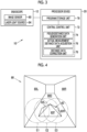
- the processor device 20 is provided with a program storage unit 70 and a central control unit 72.
- the program storage unit 70 stores a program related to various types of processing, control, or the like.
- the central control unit 72 functions as a pseudodistance data generation unit 74, an actual measurement distance data acquisition unit 76, and a distance data correction unit 78 by operating the program stored in the program storage unit 70.
- the pseudodistance data generation unit 74 generates pseudodistance data obtained by estimating the distance to the subject for a plurality of locations within an imaging range of the image sensor 60 (pseudodistance data generation step).
- a three-dimensional structure model of the subject is constructed using Structure-from-Motion (SfM). That is, the three-dimensional structure model of the subject is constructed using captured images of a plurality of frames captured by changing a relative positional relationship between the subject and the image sensor 60.
- the constructed three-dimensional structure model represents the subject as a polygonal object (a set of polygonal shapes (for example, triangular shapes)) (refer to Fig. 4 ).
- the pseudodistance data generation unit 74 calculates the distance to the subject (a distance between the subject present at each location and the tip part 36) for the plurality of locations within the imaging range based on vertex coordinates of each surface (each polygonal shape) constituting the subject. The distance to the subject at each location calculated in this manner is the pseudodistance data according to the embodiment of the present invention.
- the pseudodistance data can be generated (calculated) for any location within the imaging range.
- the location for generating (calculating) the pseudodistance data can be appropriately set.
- the pseudodistance data may be generated (calculated) for all locations within the imaging range.
- the pseudodistance data may be generated (calculated) for only a part of the locations within the imaging range, for example, a location corresponding to a vertex of each surface constituting the subject.
- the pseudodistance data at a location for which actual measurement distance data is acquired is used.
- the pseudodistance data generation unit 74 generates (calculates) the pseudodistance data for at least the location for which the actual measurement distance data is acquired.
- the actual measurement distance data acquisition unit 76 acquires the actual measurement distance data obtained by actually measuring (measuring) the distance to the subject for at least one point within the imaging range (actual measurement distance data acquisition step). Specifically, the actual measurement distance data acquisition unit 76 analyzes the captured image, actually measures (measures) the distance to the irradiation location (the subject present at the irradiation location) based on the irradiation location of the auxiliary measurement light (laser light 66) captured in the captured image, and acquires the actual measurement distance data. Each time imaging is performed (once per frame), the actual measurement distance data acquisition unit 76 actually measures (measures) the distance to the irradiation location captured in the captured image and acquires the actual measurement distance data.
- the distance data correction unit 78 corrects the pseudodistance data using the actual measurement distance data (distance data correction step).
- the distance data correction unit 78 divides the subject into a plurality of regions and performs correction (correction of the pseudodistance data using the actual measurement distance data) for each region.
- a method of performing correction for each region obtained by dividing the subject into the plurality of regions will be specifically described using Fig. 4 to Fig. 8 .
- the pseudodistance data generation unit 74 constructs a three-dimensional structure model of the inside of the tubular body 80 using the captured images P1, P2, and P3.
- the protruding portion 82 having the left inclined surface 82L, the front inclined surface 82F, and the right inclined surface 82R is present inside (on the lower interior wall 80D) the tubular body 80 having the left interior wall 80L, the lower interior wall 80D, and the right interior wall 80R (refer to Fig. 4 ).
- the pseudodistance data generation unit 74 generates the pseudodistance data using the constructed three-dimensional structure model. In the present embodiment, the pseudodistance data is generated for all locations captured in the captured images P1, P2, and P3.
- the actual measurement distance data acquisition unit 76 acquires (measures) the actual measurement distance data.
- a distance from the captured image P1 illustrated in Fig. 5 to an irradiation location LP1 (the irradiation location of the laser light 66) on the left interior wall 80L of the tubular body 80 is acquired (measured) as the actual measurement distance data.
- a distance from the captured image P2 illustrated in Fig. 6 to an irradiation location LP2 on the front inclined surface 82F of the protruding portion 82 is acquired as the actual measurement distance data.
- a distance from the captured image P3 illustrated in Fig. 7 to an irradiation location LP3 on the lower interior wall 80D of the tubular body 80 is acquired as the actual measurement distance data.
- the distance data correction unit 78 After generation of the pseudodistance data and acquisition of the actual measurement distance data are performed, the distance data correction unit 78, for a region including the location (the irradiation location of the laser light 66) at which the actual measurement distance data is acquired, calculates a scale factor for correcting the pseudodistance data of the region and corrects the pseudodistance data of the region using the calculated scale factor.
- a scale factor (hereinafter, a first scale factor) for correcting the pseudodistance data of the left interior wall 80L that is a region including the irradiation location LP1 is calculated by dividing the actual measurement distance data of the irradiation location LP1 by the pseudodistance data.
- the pseudodistance data of the left interior wall 80L is corrected by multiplying each piece of the pseudodistance data constituting the left interior wall 80L by the first scale factor.
- the distance data correction unit 78 calculates a scale factor (hereinafter, a third scale factor) for correcting the pseudodistance data of the lower interior wall 80D that is a region including the irradiation location LP3 by dividing the actual measurement distance data of the irradiation location LP3 by the pseudodistance data.
- the pseudodistance data of the lower interior wall 80D is corrected by multiplying each piece of the pseudodistance data constituting the lower interior wall 80D by the third scale factor.
- the distance data correction unit 78 corrects the pseudodistance data of the region using the scale factor calculated from the actual measurement distance data.
- the distance data correction unit 78 determines the scale factor to be used for correcting the region using the scale factor of the region for which the actual measurement distance data is present as the scale factor. Specifically, the pseudodistance data is corrected by calculating an average value of the scale factors (in the present embodiment, an average value of the first to third scale factors) of the regions for which the actual measurement distance data is present as the scale factor and multiplying each piece of the pseudodistance data constituting the region for which the actual measurement distance data is not present by the average value.
- the scale factors in the present embodiment, an average value of the first to third scale factors
- Correction of the region for which the actual measurement distance data is not present is not limited to the above method.
- a region as a correction target may be corrected using the scale factor of a region closest to the region as the correction target among the regions for which the actual measurement distance data is present or the scale factor of a region having the longest length of contact with the region as the correction target among the regions for which the actual measurement distance data is present.
- the region as the correction target may be corrected using a value obtained by calculating a weighted average of the scale factors of the regions for which the actual measurement distance data is present as the scale factor, considering an importance level of the region. In this case, it is considered to set the importance level to be higher as the region is closer to the region as the correction target or to set the importance level to be higher as the region has a longer length of contact with the region as the correction target.
- the actual measurement distance data is present for a plurality of locations within a common region.
- the scale factor for each location is calculated from the pseudodistance data and the actual measurement distance data of each location.
- the pseudodistance data of another location is corrected using the scale factor calculated from the location.
- a difference between the pseudodistance data after correction and the actual measurement distance data of the corresponding location is obtained.
- the above processing may be performed for all locations, and the pseudodistance data of the region as the correction target may be corrected using the scale factor that results in the smallest difference.
- correction may be performed using an average value of the scale factors for each location calculated from the pseudodistance data and the actual measurement distance data of each location as the scale factor.
- correction may be performed using a value obtained by calculating a weighted average of the scale factors for each location as the scale factor, considering the importance level. In this case, it is considered to set the importance level to be higher as the scale factor is calculated from the actual measurement distance data of a location closer to a center of the region as the correction target.
- the endoscope system 10 by correcting the pseudodistance data obtained by estimating the distance to the subject using the actual measurement distance data obtained by actually measuring the distance to the subject, the distance to the subject can be more accurately perceived, compared to that in a case where correction is not performed.
- a method of dividing the subject is not limited thereto and can be freely set.
- the subject may be divided into concentric regions centered at one location on the subject.
- the subject may be divided into radial regions centered at one location on the subject.
- the subject may be divided into regions of a matrix by a plurality of parallel line segments extending horizontally and vertically.
- correction may be performed without dividing the regions (using the entire subject as one region).
- the scale factor to be used for correction is determined using the same method as that in a case where the actual measurement distance data is present for the plurality of locations within the common region.
- the pseudodistance data of all locations may be corrected using the determined scale factor.
- the present invention is not limited thereto. It may be configured to actually measure (measure) the distance from the captured image of one frame to each of the plurality of locations of the subject by irradiating the subject with a plurality of beams of the laser light.
- the actual measurement distance data may be acquired (measured) by performing irradiation with light other than the laser light as the auxiliary measurement light.
- the actual measurement distance data may be acquired (measured) using a time required from irradiation of the subject with an electromagnetic wave such as the laser light to reception of a reflected wave of the electromagnetic wave with which irradiation is performed.
- the actual measurement distance data may be acquired using a time required from emission of a sound wave or an ultrasound wave other than the electromagnetic wave to reception of the reflected wave.
- a size-determined object such as a part of the tip part 36 or the forceps protruding into the body cavity from the outlet 56 of the forceps channel
- a distance to a location near or adjacent to the size-determined object may be detected (measured) based on the size of the size-determined object captured in the captured image, and the detected (measured) distance may be acquired as the actual measurement distance data.
- the pseudodistance data generation unit 74 may be configured to generate the pseudodistance data using a distance estimation model that is generated by machine learning using the captured images of the plurality of frames captured by changing the relative positional relationship between the subject and the image sensor 60.
- an image processing processor device may be provided separately from the endoscope system 10, and the image processing processor device may function as the processor according to the embodiment of the present invention.
- the image processing processor device may be configured to input the captured image captured by the endoscope 12 into the image processing processor device.
- it may be configured to generate the pseudodistance data, acquire the actual measurement distance data, and correct the pseudodistance data using the actual measurement distance data by causing a central control unit of the image processing processor device to function as the pseudodistance data generation unit 74, the actual measurement distance data acquisition unit 76, and the distance data correction unit 78 described above.
- a hardware structure of a processing unit that executes various types of processing of the central control unit 72, the pseudodistance data generation unit 74, the actual measurement distance data acquisition unit 76, the distance data correction unit 78, and the like includes various processors illustrated below.
- the various processors include a central processing unit (CPU) that is a general-purpose processor functioning as various processing units by executing software (program), a programmable logic device (PLD) such as a field programmable gate array (FPGA) that is a processor having a circuit configuration changeable after manufacture, a dedicated electric circuit that is a processor having a circuit configuration dedicatedly designed to execute various types of processing, and the like.
- CPU central processing unit
- PLD programmable logic device
- FPGA field programmable gate array
- One processing unit may be composed of one of the various processors or may be composed of a combination of two or more processors of the same type or different types (for example, a plurality of FPGAs or a combination of a CPU and an FPGA).
- a plurality of processing units may be composed of one processor.
- the plurality of processing units are composed of one processor, first, as represented by a computer such as a client and a server, a form in which one processor is composed of a combination of one or more CPUs and software and the processor functions as the plurality of processing units is possible.
- SoC system on chip
- IC integrated circuit
- the hardware structure of the various processors is, more specifically, an electric circuit (circuitry) in the form of a combination of circuit elements such as semiconductor elements.
- a hardware structure of the storage unit is a storage device such as a hard disk drive (HDD) and a solid state drive (SSD).
Landscapes
- Health & Medical Sciences (AREA)
- Life Sciences & Earth Sciences (AREA)
- Surgery (AREA)
- Engineering & Computer Science (AREA)
- Physics & Mathematics (AREA)
- Veterinary Medicine (AREA)
- General Health & Medical Sciences (AREA)
- Pathology (AREA)
- Public Health (AREA)
- Animal Behavior & Ethology (AREA)
- Biophysics (AREA)
- Biomedical Technology (AREA)
- Heart & Thoracic Surgery (AREA)
- Medical Informatics (AREA)
- Molecular Biology (AREA)
- Nuclear Medicine, Radiotherapy & Molecular Imaging (AREA)
- Optics & Photonics (AREA)
- Radiology & Medical Imaging (AREA)
- Signal Processing (AREA)
- General Physics & Mathematics (AREA)
- Theoretical Computer Science (AREA)
- Gastroenterology & Hepatology (AREA)
- Multimedia (AREA)
- Computer Vision & Pattern Recognition (AREA)
- Dentistry (AREA)
- Oral & Maxillofacial Surgery (AREA)
- Endoscopes (AREA)
Abstract
A medical endoscope system and an operation method of a medical endoscope system with which a distance to a subject can be more accurately perceived are provided.
A processor device of an endoscope system functions as a pseudodistance data generation unit (74), an actual measurement distance data acquisition unit (76), and a distance data correction unit (78). The pseudodistance data generation unit (74) generates pseudodistance data obtained by estimating a distance to a subject for a plurality of locations within an imaging range. The actual measurement distance data acquisition unit (76) acquires actual measurement distance data obtained by measuring the distance to the subject for at least one location within the imaging range. The distance data correction unit (78) corrects the pseudodistance data using the actual measurement distance data.
Description
- The present invention relates to a medical endoscope system and an operation method thereof.
-
JP2021-189822A JP2021-189822A - However, while
JP2021-189822A - The present invention is conceived in view of the above background, and an object thereof is to provide a medical endoscope system and an operation method of a medical endoscope system with which a distance to a subject can be more accurately perceived.
- In order to address the issue, a medical endoscope system according to an aspect of the present invention comprises an endoscope including an image sensor that acquires a captured image by imaging an inside of a body cavity as a subject, and a processor, in which the processor is configured to generate pseudodistance data obtained by estimating a distance to the subject for a plurality of locations within an imaging range of the image sensor using the captured image, acquire actual measurement distance data obtained by measuring the distance to the subject for at least one location within the imaging range, and correct the pseudodistance data using the actual measurement distance data.
- The pseudodistance data may be generated using a three-dimensional structure model of the subject that is constructed from captured images of a plurality of frames captured by changing a relative positional relationship between the subject and the image sensor.
- The pseudodistance data may be generated using a distance estimation model that is generated by machine learning using captured images of a plurality of frames captured by changing a relative positional relationship between the subject and the image sensor.
- The actual measurement distance data may be measured using a captured image that is captured by irradiating the subject with auxiliary measurement light of which an optical axis is inclined with respect to an imaging optical axis of the image sensor.
- The auxiliary measurement light may be laser light.
- The subject may be a gastrointestinal tract.
- The processor may be configured to, for the pseudodistance data and the actual measurement distance data of the same location, calculate a scale factor by dividing the actual measurement distance data by the pseudodistance data, and correct pseudodistance data of a location different from the same location by multiplying the pseudodistance data of the different location by the calculated scale factor.
- The processor may be configured to correct pseudodistance data of all locations by multiplying all pieces of the pseudodistance data by the scale factor.
- The processor may be configured to divide the subject into a plurality of regions, and correct pseudodistance data of a region including the same location by multiplying the pseudodistance data within the region including the same location by the scale factor.
- The processor may be configured to, for a region for which the actual measurement distance data is not present, determine a scale factor to be used for correcting the region using a scale factor used for correcting a region for which the actual measurement distance data is present.
- The processor may be configured to correct the region for which the actual measurement distance data is not present using an average value of the scale factors used for correcting the region for which the actual measurement distance data is present as the scale factor.
- The processor may be configured to, for a region for which a plurality of pieces of the actual measurement distance data are present, determine a scale factor to be used for correcting the region using a scale factor of each location for which the actual measurement distance data is present.
- The processor may be configured to correct the region for which the plurality of pieces of actual measurement distance data are present using an average value of the scale factors of each location for which the actual measurement distance data is present as the scale factor.
- Of course, in the medical endoscope system according to the aspect of the present invention, any plurality of configurations among the above various configurations may be combined with each other.
- In addition, in order to address the issue, an operation method of a medical endoscope system according to another aspect of the present invention comprises a pseudodistance data generation step of generating pseudodistance data obtained by estimating a distance to a subject for a plurality of locations within an imaging range of an image sensor of an endoscope using a captured image captured by the image sensor, an actual measurement distance data acquisition step of acquiring actual measurement distance data obtained by measuring the distance to the subject for at least one location within the imaging range, and a distance data correction step of correcting the pseudodistance data using the actual measurement distance data.
- According to the present invention, the distance to the subject can be more accurately perceived.
-
-
Fig. 1 is a schematic diagram of an endoscope system. -
Fig. 2 is a plan view illustrating a tip part of an endoscope. -
Fig. 3 is a block diagram illustrating functions of the endoscope system. -
Fig. 4 is a descriptive diagram illustrating a sleeve-shaped object and a protruding portion inside the sleeve-shaped object. -
Fig. 5 is a descriptive diagram illustrating a captured image obtained by capturing an imaging range E1 inFig. 4 . -
Fig. 6 is a descriptive diagram illustrating a captured image obtained by capturing an imaging range E2 inFig. 4 . -
Fig. 7 is a descriptive diagram illustrating a captured image obtained by capturing an imaging range E3 inFig. 4 . -
Fig. 8 is a flowchart illustrating a correction procedure of pseudodistance data. - As illustrated in
Fig. 1 , anendoscope system 10 according to an embodiment of the present invention is a medical endoscope system used for medical purposes and includes anendoscope 12, alight source device 14, adisplay 16, auser interface 18, and a processor device 20 (processor). - In the
endoscope system 10, theendoscope 12 is optically connected to thelight source device 14 and is electrically connected to theprocessor device 20. In addition, in theendoscope system 10, theprocessor device 20 is electrically connected to each unit (theendoscope 12, thelight source device 14, thedisplay 16, and the user interface 18) of theendoscope system 10. - The
endoscope 12 includes, for example, aninsertion part 30 inserted into a body cavity such as a gastrointestinal tract, anoperating part 32 connected to a proximal end side of theinsertion part 30, and abendable part 34 and atip part 36 provided on a distal end side of theinsertion part 30. Theoperating part 32 is provided with aninlet 38 of a forceps channel for inserting a treatment tool such as forceps. In addition, theoperating part 32 is provided with various operating members that receive operations such as bending of thebendable part 34, zooming during subject imaging, a still image/video image capturing instruction, switching of an imaging mode, air supply, and water supply from a user. In the present embodiment,rotary dials push buttons - As illustrated in
Fig. 2 , thetip part 36 is provided with anillumination window 52 for emitting illumination light, anobservation window 54 for capturing reflected light of the illumination light reflected by a subject, anoutlet 56 of the forceps channel, and an air supply andwater supply port 58. - An image sensor 60 (refer to
Fig. 1 ) is provided behind theobservation window 54. Theimage sensor 60 is an image sensor such as a charge coupled device (CCD) or a complementary MOS (CMOS) that outputs a captured image as a digital image signal and images a space in front of the tip part 36 (in front of the subject). The image (captured image) captured by theimage sensor 60 is input into theprocessor device 20. - In addition, the
tip part 36 is provided with an auxiliary measurementlight exit window 62 for emitting auxiliary measurement light for actually measuring (measuring) a distance to the subject. The auxiliary measurement light is light of which an optical axis is inclined with respect to an imaging optical axis of the endoscope 12 (image sensor 60). In the present embodiment, the auxiliary measurementlight exit window 62 is provided below theobservation window 54, and laser light 66 (refer toFig. 5, Fig. 6 , andFig. 7 ) from a laser light source 64 (refer toFig. 3 ) is emitted upward in an inclined direction in front of thetip part 36 as the auxiliary measurement light from the auxiliary measurementlight exit window 62. - The
laser light 66 emitted from the auxiliary measurementlight exit window 62 can advance higher as the distance to the subject is increased. Thus, a height of an irradiation location of thelaser light 66 captured in the captured image is increased as the distance to the subject is increased. By using this property, a distance to the irradiation location (the subject present at the irradiation location) is actually measured (measured) based on the irradiation location of thelaser light 66 captured in the captured image in theendoscope system 10. - With reference to
Fig. 1 again, thelight source device 14 supplies the illumination light to theendoscope 12. Thedisplay 16 is, for example, a well-known liquid crystal display and displays the captured image captured by the endoscope 12 (image sensor 60), a result of image analysis performed by theprocessor device 20, and the like. Theuser interface 18 is an input device for performing input and the like into theprocessor device 20 and is a keyboard, a mouse, a foot pedal, a touch panel, a microphone, and/or a motion sensor or the like. - As illustrated in
Fig. 3 , theprocessor device 20 is provided with aprogram storage unit 70 and acentral control unit 72. Theprogram storage unit 70 stores a program related to various types of processing, control, or the like. Thecentral control unit 72 functions as a pseudodistancedata generation unit 74, an actual measurement distancedata acquisition unit 76, and a distancedata correction unit 78 by operating the program stored in theprogram storage unit 70. - The pseudodistance
data generation unit 74 generates pseudodistance data obtained by estimating the distance to the subject for a plurality of locations within an imaging range of the image sensor 60 (pseudodistance data generation step). Specifically, a three-dimensional structure model of the subject is constructed using Structure-from-Motion (SfM). That is, the three-dimensional structure model of the subject is constructed using captured images of a plurality of frames captured by changing a relative positional relationship between the subject and theimage sensor 60. - The constructed three-dimensional structure model, for example, represents the subject as a polygonal object (a set of polygonal shapes (for example, triangular shapes)) (refer to
Fig. 4 ). The pseudodistancedata generation unit 74 calculates the distance to the subject (a distance between the subject present at each location and the tip part 36) for the plurality of locations within the imaging range based on vertex coordinates of each surface (each polygonal shape) constituting the subject. The distance to the subject at each location calculated in this manner is the pseudodistance data according to the embodiment of the present invention. - By using the three-dimensional structure model of the subject (the vertex coordinates of each surface constituting the subject), the pseudodistance data can be generated (calculated) for any location within the imaging range. Thus, the location for generating (calculating) the pseudodistance data can be appropriately set. For example, the pseudodistance data may be generated (calculated) for all locations within the imaging range. In addition, the pseudodistance data may be generated (calculated) for only a part of the locations within the imaging range, for example, a location corresponding to a vertex of each surface constituting the subject. However, in correcting the pseudodistance data described later, the pseudodistance data at a location for which actual measurement distance data is acquired is used. Thus, the pseudodistance
data generation unit 74 generates (calculates) the pseudodistance data for at least the location for which the actual measurement distance data is acquired. - The actual measurement distance
data acquisition unit 76 acquires the actual measurement distance data obtained by actually measuring (measuring) the distance to the subject for at least one point within the imaging range (actual measurement distance data acquisition step). Specifically, the actual measurement distancedata acquisition unit 76 analyzes the captured image, actually measures (measures) the distance to the irradiation location (the subject present at the irradiation location) based on the irradiation location of the auxiliary measurement light (laser light 66) captured in the captured image, and acquires the actual measurement distance data. Each time imaging is performed (once per frame), the actual measurement distancedata acquisition unit 76 actually measures (measures) the distance to the irradiation location captured in the captured image and acquires the actual measurement distance data. - The distance
data correction unit 78 corrects the pseudodistance data using the actual measurement distance data (distance data correction step). In the present embodiment, the distancedata correction unit 78 divides the subject into a plurality of regions and performs correction (correction of the pseudodistance data using the actual measurement distance data) for each region. Hereinafter, a method of performing correction for each region obtained by dividing the subject into the plurality of regions will be specifically described usingFig. 4 to Fig. 8 . - Hereinafter, a case where captured images P1, P2, and P3 illustrated in
Fig. 5, Fig. 6 , andFig. 7 , respectively, are acquired for the subject in which a protrudingportion 82 of a square pyramid shape that is found in a lesion portion (tumor) and that has a leftinclined surface 82L, a frontinclined surface 82F, and a rightinclined surface 82R is present inside (on a lowerinterior wall 80D) atubular body 80 that is found in the gastrointestinal tract and that has a leftinterior wall 80L, the lowerinterior wall 80D, and a rightinterior wall 80R as illustrated inFig. 4 , by bending thebendable part 34 of theendoscope 12 right and left inside the subject (tubular body 80) to perform imaging in an order of imaging ranges E1, E2, and E3 will be described. - As illustrated in
Fig. 8 , in a case where the captured images P1, P2, and P3 (refer toFig. 5, Fig. 6 , andFig. 7 ) are acquired by performing imaging in the order of the imaging ranges E1, E2, and E3 (refer toFig. 4 ), the pseudodistancedata generation unit 74 constructs a three-dimensional structure model of the inside of thetubular body 80 using the captured images P1, P2, and P3. In the constructed three-dimensional structure model, the protrudingportion 82 having the leftinclined surface 82L, the frontinclined surface 82F, and the rightinclined surface 82R is present inside (on the lowerinterior wall 80D) thetubular body 80 having the leftinterior wall 80L, the lowerinterior wall 80D, and the rightinterior wall 80R (refer toFig. 4 ). The pseudodistancedata generation unit 74 generates the pseudodistance data using the constructed three-dimensional structure model. In the present embodiment, the pseudodistance data is generated for all locations captured in the captured images P1, P2, and P3. - In addition, in a case where the captured images P1, P2, and P3 are acquired, the actual measurement distance
data acquisition unit 76 acquires (measures) the actual measurement distance data. In the present example, a distance from the captured image P1 illustrated inFig. 5 to an irradiation location LP1 (the irradiation location of the laser light 66) on the leftinterior wall 80L of thetubular body 80 is acquired (measured) as the actual measurement distance data. In addition, a distance from the captured image P2 illustrated inFig. 6 to an irradiation location LP2 on the frontinclined surface 82F of the protrudingportion 82 is acquired as the actual measurement distance data. Furthermore, a distance from the captured image P3 illustrated inFig. 7 to an irradiation location LP3 on the lowerinterior wall 80D of thetubular body 80 is acquired as the actual measurement distance data. - After generation of the pseudodistance data and acquisition of the actual measurement distance data are performed, the distance
data correction unit 78, for a region including the location (the irradiation location of the laser light 66) at which the actual measurement distance data is acquired, calculates a scale factor for correcting the pseudodistance data of the region and corrects the pseudodistance data of the region using the calculated scale factor. - Specifically, for the irradiation location LP1 of the captured image P1 illustrated in
Fig. 5 , a scale factor (hereinafter, a first scale factor) for correcting the pseudodistance data of the leftinterior wall 80L that is a region including the irradiation location LP1 is calculated by dividing the actual measurement distance data of the irradiation location LP1 by the pseudodistance data. The pseudodistance data of the leftinterior wall 80L is corrected by multiplying each piece of the pseudodistance data constituting the leftinterior wall 80L by the first scale factor. - Similarly, for the irradiation location LP2 of the captured image P2 illustrated in
Fig. 6 , the distancedata correction unit 78 calculates a scale factor (hereinafter, a second scale factor) for correcting the pseudodistance data of the frontinclined surface 82F that is a region including the irradiation location LP2 by dividing the actual measurement distance data of the irradiation location LP2 by the pseudodistance data. The pseudodistance data of the frontinclined surface 82F is corrected by multiplying each piece of the pseudodistance data constituting the frontinclined surface 82F by the second scale factor. - Furthermore, for the irradiation location LP3 of the captured image P3 illustrated in
Fig. 7 , the distancedata correction unit 78 calculates a scale factor (hereinafter, a third scale factor) for correcting the pseudodistance data of the lowerinterior wall 80D that is a region including the irradiation location LP3 by dividing the actual measurement distance data of the irradiation location LP3 by the pseudodistance data. The pseudodistance data of the lowerinterior wall 80D is corrected by multiplying each piece of the pseudodistance data constituting the lowerinterior wall 80D by the third scale factor. - As described above, for the region for which the actual measurement distance data is present, the distance
data correction unit 78 corrects the pseudodistance data of the region using the scale factor calculated from the actual measurement distance data. - On the other hand, for the region such as the left inclined
surface 82L and the rightinclined surface 82R for which the actual measurement distance data is not present, the distancedata correction unit 78 determines the scale factor to be used for correcting the region using the scale factor of the region for which the actual measurement distance data is present as the scale factor. Specifically, the pseudodistance data is corrected by calculating an average value of the scale factors (in the present embodiment, an average value of the first to third scale factors) of the regions for which the actual measurement distance data is present as the scale factor and multiplying each piece of the pseudodistance data constituting the region for which the actual measurement distance data is not present by the average value. - Correction of the region for which the actual measurement distance data is not present is not limited to the above method. For example, a region as a correction target may be corrected using the scale factor of a region closest to the region as the correction target among the regions for which the actual measurement distance data is present or the scale factor of a region having the longest length of contact with the region as the correction target among the regions for which the actual measurement distance data is present.
- In addition, instead of the above average value, the region as the correction target may be corrected using a value obtained by calculating a weighted average of the scale factors of the regions for which the actual measurement distance data is present as the scale factor, considering an importance level of the region. In this case, it is considered to set the importance level to be higher as the region is closer to the region as the correction target or to set the importance level to be higher as the region has a longer length of contact with the region as the correction target.
- In addition, it is considered that the actual measurement distance data is present for a plurality of locations within a common region. In this case, the scale factor for each location is calculated from the pseudodistance data and the actual measurement distance data of each location. Next, for any one location, the pseudodistance data of another location is corrected using the scale factor calculated from the location. Next, a difference between the pseudodistance data after correction and the actual measurement distance data of the corresponding location is obtained. The above processing may be performed for all locations, and the pseudodistance data of the region as the correction target may be corrected using the scale factor that results in the smallest difference.
- In a case where the actual measurement distance data is present for the plurality of locations within the common region, correction may be performed using an average value of the scale factors for each location calculated from the pseudodistance data and the actual measurement distance data of each location as the scale factor. In addition, correction may be performed using a value obtained by calculating a weighted average of the scale factors for each location as the scale factor, considering the importance level. In this case, it is considered to set the importance level to be higher as the scale factor is calculated from the actual measurement distance data of a location closer to a center of the region as the correction target.
- As described above, according to the
endoscope system 10 according to the embodiment of the present invention, by correcting the pseudodistance data obtained by estimating the distance to the subject using the actual measurement distance data obtained by actually measuring the distance to the subject, the distance to the subject can be more accurately perceived, compared to that in a case where correction is not performed. - While an example of dividing the subject into regions based on the three-dimensional structure model of the subject constructed by the pseudodistance
data generation unit 74 in dividing the subject into the plurality of regions has been described in the embodiment, a method of dividing the subject is not limited thereto and can be freely set. For example, the subject may be divided into concentric regions centered at one location on the subject. In addition, the subject may be divided into radial regions centered at one location on the subject. Furthermore, the subject may be divided into regions of a matrix by a plurality of parallel line segments extending horizontally and vertically. - In addition, while an example of performing correction for each region by dividing the subject into the plurality of regions has been described in the embodiment, correction may be performed without dividing the regions (using the entire subject as one region). In this case, the scale factor to be used for correction is determined using the same method as that in a case where the actual measurement distance data is present for the plurality of locations within the common region. The pseudodistance data of all locations may be corrected using the determined scale factor.
- In addition, while an example of actually measuring (measuring) the distance from the captured image of one frame to one location of the subject by irradiating the subject with one beam of the laser light has been described in the embodiment, the present invention is not limited thereto. It may be configured to actually measure (measure) the distance from the captured image of one frame to each of the plurality of locations of the subject by irradiating the subject with a plurality of beams of the laser light.
- Furthermore, while an example of acquiring (measuring) the actual measurement distance data by performing irradiation with the laser light as the auxiliary measurement light has been described in the embodiment, the actual measurement distance data may be acquired (measured) by performing irradiation with light other than the laser light as the auxiliary measurement light. In addition, while an example of acquiring the actual measurement distance data based on the irradiation location of the laser light has been described, the actual measurement distance data may be acquired (measured) using a time required from irradiation of the subject with an electromagnetic wave such as the laser light to reception of a reflected wave of the electromagnetic wave with which irradiation is performed. Of course, the actual measurement distance data may be acquired using a time required from emission of a sound wave or an ultrasound wave other than the electromagnetic wave to reception of the reflected wave.
- Furthermore, an object of which a size is determined in advance (hereinafter, a size-determined object), such as a part of the
tip part 36 or the forceps protruding into the body cavity from theoutlet 56 of the forceps channel, is also captured in the captured image captured by theendoscope 12. Thus, a distance to a location near or adjacent to the size-determined object may be detected (measured) based on the size of the size-determined object captured in the captured image, and the detected (measured) distance may be acquired as the actual measurement distance data. - In addition, while an example in which the pseudodistance
data generation unit 74 generates the pseudodistance data using the three-dimensional structure model of the subject constructed from the captured image of the plurality of frames captured by changing the relative positional relationship between the subject and theimage sensor 60 has been described in the embodiment, the present invention is not limited thereto. The pseudodistancedata generation unit 74 may be configured to generate the pseudodistance data using a distance estimation model that is generated by machine learning using the captured images of the plurality of frames captured by changing the relative positional relationship between the subject and theimage sensor 60. - Furthermore, while an example in which the
processor device 20 of theendoscope system 10 functions as the processor according to the embodiment of the present invention has been described in the embodiment, an image processing processor device may be provided separately from theendoscope system 10, and the image processing processor device may function as the processor according to the embodiment of the present invention. In this case, it may be configured to input the captured image captured by theendoscope 12 into the image processing processor device. In addition, it may be configured to generate the pseudodistance data, acquire the actual measurement distance data, and correct the pseudodistance data using the actual measurement distance data by causing a central control unit of the image processing processor device to function as the pseudodistancedata generation unit 74, the actual measurement distancedata acquisition unit 76, and the distancedata correction unit 78 described above. - In the embodiment, a hardware structure of a processing unit that executes various types of processing of the
central control unit 72, the pseudodistancedata generation unit 74, the actual measurement distancedata acquisition unit 76, the distancedata correction unit 78, and the like includes various processors illustrated below. The various processors include a central processing unit (CPU) that is a general-purpose processor functioning as various processing units by executing software (program), a programmable logic device (PLD) such as a field programmable gate array (FPGA) that is a processor having a circuit configuration changeable after manufacture, a dedicated electric circuit that is a processor having a circuit configuration dedicatedly designed to execute various types of processing, and the like. - One processing unit may be composed of one of the various processors or may be composed of a combination of two or more processors of the same type or different types (for example, a plurality of FPGAs or a combination of a CPU and an FPGA). In addition, a plurality of processing units may be composed of one processor. As an example in which the plurality of processing units are composed of one processor, first, as represented by a computer such as a client and a server, a form in which one processor is composed of a combination of one or more CPUs and software and the processor functions as the plurality of processing units is possible. Second, as represented by a system on chip (SoC) and the like, a form of using a processor that implements functions of the entire system including the plurality of processing units in one integrated circuit (IC) chip is possible. Accordingly, various processing units are configured using one or more of the various processors as a hardware structure.
- Furthermore, the hardware structure of the various processors is, more specifically, an electric circuit (circuitry) in the form of a combination of circuit elements such as semiconductor elements. In addition, a hardware structure of the storage unit is a storage device such as a hard disk drive (HDD) and a solid state drive (SSD).
-
- 10: endoscope system (medical endoscope system)
- 12: endoscope
- 14: light source device
- 16: display
- 18: user interface
- 20: processor device (processor)
- 30: insertion part
- 32: operating part
- 34: bendable part
- 36: tip part
- 38: inlet
- 40, 42, 44: rotary dial
- 46, 48, 50: push button
- 52: illumination window
- 54: observation window
- 56: outlet
- 58: air supply and water supply port
- 60: image sensor
- 62: auxiliary measurement light exit window
- 64: laser light source
- 66: laser light
- 70: program storage unit
- 72: central control unit
- 74: pseudodistance data generation unit
- 76: actual measurement distance data acquisition unit
- 78: distance data correction unit
- 80: tubular body
- 80L: left interior wall
- 80D: lower interior wall
- 80R: right interior wall
- 82: protruding portion
- 82L: left inclined surface
- 82F: front inclined surface
- 82R: right inclined surface
- E1, E2, E3: imaging range
- P1, P2, P3: captured image
- LP1, LP2, LP3: irradiation location
Claims (14)
- A medical endoscope system comprising:an endoscope (12) including an image sensor (60) that acquires a captured image (P1, P2, P3) by imaging an inside of a body cavity as a subject; andone or more processors (20) configured to:generate pseudodistance data by estimating a distance to the subject for a plurality of locations within an imaging range of the image sensor using the captured image;acquire actual measurement distance data by measuring the distance to the subject for at least one location within the imaging range; andcorrect the pseudodistance data using the actual measurement distance data.
- The medical endoscope system according to claim 1,
wherein the pseudodistance data is generated using a three-dimensional structure model of the subject that is constructed from a plurality of frames of the captured images obtained while changing a relative positional relationship between the subject and the image sensor (60). - The medical endoscope system according to claim 1,
wherein the pseudodistance data is generated using a distance estimation model that is generated by machine learning using a plurality of frames of the captured images obtained while changing a relative positional relationship between the subject and the image sensor (60). - The medical endoscope system according to claim 1,
wherein the actual measurement distance data is measured using the captured image obtained by irradiating the subject with auxiliary measurement light of which an optical axis is inclined with respect to an imaging optical axis of the image sensor (60). - The medical endoscope system according to claim 4,
wherein the auxiliary measurement light is laser light (66). - The medical endoscope system according to claim 5,
wherein the subject is a gastrointestinal tract. - The medical endoscope system according to any one of claims 1 to 6,
wherein the one or more processors (20) are configured to:calculate a scale factor by dividing the actual measurement distance data by the pseudodistance data of the same location; andcorrect the pseudodistance data of a different location by multiplying the pseudodistance data of the different location by the calculated scale factor. - The medical endoscope system according to claim 7,
wherein the one or more processors (20) are configured to correct the pseudodistance data of all locations by multiplying each piece of the pseudodistance data by the calculated scale factor. - The medical endoscope system according to claim 7,
wherein the one or more processors (20) are configured to:divide the subject into a plurality of regions; andcorrect the pseudodistance data of a region including the same location by multiplying the pseudodistance data within the region including the same location by the scale factor. - The medical endoscope system according to claim 9,
wherein the one or more processors (20) are configured to determine a scale factor for correcting a region lacking the actual measurement distance data using a scale factor for correcting a region with the actual measurement distance data. - The medical endoscope system according to claim 10,
wherein the one or more processors (20) are configured to correct the region lacking the actual measurement distance data using an average value of the scale factors used for correcting the regions with the actual measurement distance data, as the scale factor. - The medical endoscope system according to claim 9,
wherein the one or more processors (20) are configured to determine a scale factor to be used for correcting a region with a plurality of pieces of the actual measurement distance data using scale factors for each of these locations with the actual measurement distance data. - The medical endoscope system according to claim 12,
wherein the one or more processors (20) are configured to correct the region with the plurality of pieces of actual measurement distance data using an average value of the scale factors for each of these locations with the actual measurement distance data, as the scale factor. - An operation method of a medical endoscope system, the method comprising:a pseudodistance data generation step of generating pseudodistance data by estimating a distance to a subject for a plurality of locations within an imaging range of an image sensor of an endoscope using a captured image captured by the image sensor;an actual measurement distance data acquisition step of acquiring actual measurement distance data by measuring the distance to the subject for at least one location within the imaging range; anda distance data correction step of correcting the pseudodistance data using the actual measurement distance data.
Applications Claiming Priority (1)
| Application Number | Priority Date | Filing Date | Title |
|---|---|---|---|
| JP2023032566A JP2024124700A (en) | 2023-03-03 | 2023-03-03 | Medical endoscope system and method of operation thereof |
Publications (1)
| Publication Number | Publication Date |
|---|---|
| EP4424226A1 true EP4424226A1 (en) | 2024-09-04 |
Family
ID=90057372
Family Applications (1)
| Application Number | Title | Priority Date | Filing Date |
|---|---|---|---|
| EP24159475.3A Pending EP4424226A1 (en) | 2023-03-03 | 2024-02-23 | Medical endoscope system and operation method thereof |
Country Status (3)
| Country | Link |
|---|---|
| US (1) | US20240293000A1 (en) |
| EP (1) | EP4424226A1 (en) |
| JP (1) | JP2024124700A (en) |
Citations (5)
| Publication number | Priority date | Publication date | Assignee | Title |
|---|---|---|---|---|
| JPH0926547A (en) * | 1995-07-10 | 1997-01-28 | Olympus Optical Co Ltd | Endoscopic image processing device |
| JP2021189822A (en) | 2020-06-01 | 2021-12-13 | オリンパス株式会社 | Image processing system, image processing method, and image processing program |
| US20220095889A1 (en) * | 2019-07-23 | 2022-03-31 | Hoya Corporation | Program, information processing method, and information processing apparatus |
| WO2022202520A1 (en) * | 2021-03-26 | 2022-09-29 | 富士フイルム株式会社 | Medical information processing device, endoscope system, medical information processing method, and medical information processing program |
| US20220358750A1 (en) * | 2021-05-06 | 2022-11-10 | Fujifilm Corporation | Learning device, depth information acquisition device, endoscope system, learning method, and program |
Family Cites Families (3)
| Publication number | Priority date | Publication date | Assignee | Title |
|---|---|---|---|---|
| JP2011069965A (en) * | 2009-09-25 | 2011-04-07 | Japan Atomic Energy Agency | Image capturing apparatus, image display method, and recording medium with image display program recorded thereon |
| EP4083677A4 (en) * | 2019-12-25 | 2023-02-01 | FUJIFILM Corporation | ENDOSCOPE DEVICE, ITS METHOD OF USE AND PROGRAM FOR THE ENDOSCOPE DEVICE |
| US12205314B2 (en) * | 2022-09-06 | 2025-01-21 | Olympus Medical Systems Corp. | Image processing apparatus for a plurality of timeseries images acquired by an endoscope, image processing method, and recording medium |
-
2023
- 2023-03-03 JP JP2023032566A patent/JP2024124700A/en active Pending
-
2024
- 2024-02-23 EP EP24159475.3A patent/EP4424226A1/en active Pending
- 2024-02-28 US US18/590,889 patent/US20240293000A1/en active Pending
Patent Citations (5)
| Publication number | Priority date | Publication date | Assignee | Title |
|---|---|---|---|---|
| JPH0926547A (en) * | 1995-07-10 | 1997-01-28 | Olympus Optical Co Ltd | Endoscopic image processing device |
| US20220095889A1 (en) * | 2019-07-23 | 2022-03-31 | Hoya Corporation | Program, information processing method, and information processing apparatus |
| JP2021189822A (en) | 2020-06-01 | 2021-12-13 | オリンパス株式会社 | Image processing system, image processing method, and image processing program |
| WO2022202520A1 (en) * | 2021-03-26 | 2022-09-29 | 富士フイルム株式会社 | Medical information processing device, endoscope system, medical information processing method, and medical information processing program |
| US20220358750A1 (en) * | 2021-05-06 | 2022-11-10 | Fujifilm Corporation | Learning device, depth information acquisition device, endoscope system, learning method, and program |
Also Published As
| Publication number | Publication date |
|---|---|
| US20240293000A1 (en) | 2024-09-05 |
| JP2024124700A (en) | 2024-09-13 |
Similar Documents
| Publication | Publication Date | Title |
|---|---|---|
| CN102762142B (en) | The laser enhancing on 3D surface is rebuild | |
| JP7335157B2 (en) | LEARNING DATA GENERATION DEVICE, OPERATION METHOD OF LEARNING DATA GENERATION DEVICE, LEARNING DATA GENERATION PROGRAM, AND MEDICAL IMAGE RECOGNITION DEVICE | |
| US10743843B2 (en) | Information processing apparatus, ultrasonic imaging apparatus, and information processing method | |
| JP5837261B2 (en) | Multi-camera device tracking | |
| CN111970986A (en) | System and method for performing intraoperative guidance | |
| JP7385731B2 (en) | Endoscope system, image processing device operating method, and endoscope | |
| US20130345509A1 (en) | System and method for endoscopic measurement and mapping of internal organs, tumors and other objects | |
| US20120253173A1 (en) | Image processing apparatus, ultrasonic photographing system, image processing method therefor, and storage medium storing program | |
| JP2015100712A (en) | Surgical needle for surgical system with optical recognition function | |
| KR20190101694A (en) | Method and apparatus for improving matching performance between ct data and optical data | |
| US12433478B2 (en) | Processing device, endoscope system, and method for processing captured image | |
| EP3705023B1 (en) | Endoscope apparatus, calibration device, and calibration method | |
| JP2008504055A (en) | Image processing system especially for implant images | |
| EP4424226A1 (en) | Medical endoscope system and operation method thereof | |
| JP2006320427A (en) | Endoscopic operation support system | |
| CN110769731B (en) | Endoscope system, processing system for endoscope, image processing method | |
| EP2777593A2 (en) | Real time image guidance system | |
| WO2022230563A1 (en) | Endoscope system and operation method for same | |
| US11490784B2 (en) | Endoscope apparatus | |
| US20240000299A1 (en) | Image processing apparatus, image processing method, and program | |
| CN117958721A (en) | Endoscopic image compensation method, device, endoscope and storage medium | |
| CN111631720A (en) | Mapping of body cavities | |
| CN120226044A (en) | System and method for registering virtual 3D models through semi-transparent display | |
| US20250176995A1 (en) | Processor device and operation method of processor device | |
| US12277626B2 (en) | Information processing apparatus, information processing system, information processing method, and information processing program |
Legal Events
| Date | Code | Title | Description |
|---|---|---|---|
| PUAI | Public reference made under article 153(3) epc to a published international application that has entered the european phase |
Free format text: ORIGINAL CODE: 0009012 |
|
| STAA | Information on the status of an ep patent application or granted ep patent |
Free format text: STATUS: THE APPLICATION HAS BEEN PUBLISHED |
|
| AK | Designated contracting states |
Kind code of ref document: A1 Designated state(s): AL AT BE BG CH CY CZ DE DK EE ES FI FR GB GR HR HU IE IS IT LI LT LU LV MC ME MK MT NL NO PL PT RO RS SE SI SK SM TR |
|
| STAA | Information on the status of an ep patent application or granted ep patent |
Free format text: STATUS: REQUEST FOR EXAMINATION WAS MADE |
|
| 17P | Request for examination filed |
Effective date: 20250303 |