EP4424196A1 - Sole and shoe - Google Patents
Sole and shoe Download PDFInfo
- Publication number
- EP4424196A1 EP4424196A1 EP24160313.3A EP24160313A EP4424196A1 EP 4424196 A1 EP4424196 A1 EP 4424196A1 EP 24160313 A EP24160313 A EP 24160313A EP 4424196 A1 EP4424196 A1 EP 4424196A1
- Authority
- EP
- European Patent Office
- Prior art keywords
- foot
- sole
- midsole
- recessed
- width direction
- Prior art date
- Legal status (The legal status is an assumption and is not a legal conclusion. Google has not performed a legal analysis and makes no representation as to the accuracy of the status listed.)
- Granted
Links
Images


Classifications
-
- A—HUMAN NECESSITIES
- A43—FOOTWEAR
- A43B—CHARACTERISTIC FEATURES OF FOOTWEAR; PARTS OF FOOTWEAR
- A43B13/00—Soles; Sole-and-heel integral units
- A43B13/02—Soles; Sole-and-heel integral units characterised by the material
- A43B13/12—Soles with several layers of different materials
- A43B13/125—Soles with several layers of different materials characterised by the midsole or middle layer
- A43B13/127—Soles with several layers of different materials characterised by the midsole or middle layer the midsole being multilayer
-
- A—HUMAN NECESSITIES
- A43—FOOTWEAR
- A43B—CHARACTERISTIC FEATURES OF FOOTWEAR; PARTS OF FOOTWEAR
- A43B13/00—Soles; Sole-and-heel integral units
- A43B13/02—Soles; Sole-and-heel integral units characterised by the material
- A43B13/12—Soles with several layers of different materials
- A43B13/125—Soles with several layers of different materials characterised by the midsole or middle layer
-
- A—HUMAN NECESSITIES
- A43—FOOTWEAR
- A43B—CHARACTERISTIC FEATURES OF FOOTWEAR; PARTS OF FOOTWEAR
- A43B13/00—Soles; Sole-and-heel integral units
- A43B13/14—Soles; Sole-and-heel integral units characterised by the constructive form
-
- A—HUMAN NECESSITIES
- A43—FOOTWEAR
- A43B—CHARACTERISTIC FEATURES OF FOOTWEAR; PARTS OF FOOTWEAR
- A43B13/00—Soles; Sole-and-heel integral units
- A43B13/14—Soles; Sole-and-heel integral units characterised by the constructive form
- A43B13/143—Soles; Sole-and-heel integral units characterised by the constructive form provided with wedged, concave or convex end portions, e.g. for improving roll-off of the foot
- A43B13/146—Concave end portions, e.g. with a cavity or cut-out portion
-
- A—HUMAN NECESSITIES
- A43—FOOTWEAR
- A43B—CHARACTERISTIC FEATURES OF FOOTWEAR; PARTS OF FOOTWEAR
- A43B13/00—Soles; Sole-and-heel integral units
- A43B13/14—Soles; Sole-and-heel integral units characterised by the constructive form
- A43B13/18—Resilient soles
- A43B13/181—Resiliency achieved by the structure of the sole
- A43B13/183—Leaf springs
-
- A—HUMAN NECESSITIES
- A43—FOOTWEAR
- A43B—CHARACTERISTIC FEATURES OF FOOTWEAR; PARTS OF FOOTWEAR
- A43B13/00—Soles; Sole-and-heel integral units
- A43B13/14—Soles; Sole-and-heel integral units characterised by the constructive form
- A43B13/18—Resilient soles
- A43B13/181—Resiliency achieved by the structure of the sole
- A43B13/186—Differential cushioning region, e.g. cushioning located under the ball of the foot
-
- A—HUMAN NECESSITIES
- A43—FOOTWEAR
- A43B—CHARACTERISTIC FEATURES OF FOOTWEAR; PARTS OF FOOTWEAR
- A43B23/00—Uppers; Boot legs; Stiffeners; Other single parts of footwear
- A43B23/02—Uppers; Boot legs
- A43B23/0245—Uppers; Boot legs characterised by the constructive form
-
- A—HUMAN NECESSITIES
- A43—FOOTWEAR
- A43B—CHARACTERISTIC FEATURES OF FOOTWEAR; PARTS OF FOOTWEAR
- A43B5/00—Footwear for sporting purposes
- A43B5/06—Running shoes; Track shoes
-
- A—HUMAN NECESSITIES
- A43—FOOTWEAR
- A43B—CHARACTERISTIC FEATURES OF FOOTWEAR; PARTS OF FOOTWEAR
- A43B7/00—Footwear with health or hygienic arrangements
- A43B7/14—Footwear with health or hygienic arrangements with foot-supporting parts
- A43B7/1405—Footwear with health or hygienic arrangements with foot-supporting parts with pads or holes on one or more locations, or having an anatomical or curved form
- A43B7/1415—Footwear with health or hygienic arrangements with foot-supporting parts with pads or holes on one or more locations, or having an anatomical or curved form characterised by the location under the foot
-
- A—HUMAN NECESSITIES
- A43—FOOTWEAR
- A43B—CHARACTERISTIC FEATURES OF FOOTWEAR; PARTS OF FOOTWEAR
- A43B7/00—Footwear with health or hygienic arrangements
- A43B7/14—Footwear with health or hygienic arrangements with foot-supporting parts
- A43B7/1405—Footwear with health or hygienic arrangements with foot-supporting parts with pads or holes on one or more locations, or having an anatomical or curved form
- A43B7/1415—Footwear with health or hygienic arrangements with foot-supporting parts with pads or holes on one or more locations, or having an anatomical or curved form characterised by the location under the foot
- A43B7/1445—Footwear with health or hygienic arrangements with foot-supporting parts with pads or holes on one or more locations, or having an anatomical or curved form characterised by the location under the foot situated under the midfoot, i.e. the second, third or fourth metatarsal
Definitions
- the present disclosure relates to a sole and a shoe.
- PCT International Publication No. 2020/136916 discloses a shoe capable of reducing a burden on an ankle joint.
- the sole of the shoe includes a rear bottom surface portion that, when placed on the flat virtual plane, comes into contact with the virtual plane, a toe portion having a height from the virtual plane that is greater than or equal to 170% and less than or equal to 250% with respect to a thickness dimension in the rear bottom surface portion, and a front bottom surface portion that is continuous with a front portion of the rear bottom surface portion, extends to the toe portion in a curved manner, and is separated from the virtual plane.
- An object of the present disclosure is to provide a sole and a shoe capable of reducing a change in angle of an ankle joint from landing to taking off.
- a sole according to one aspect of the present disclosure is a sole constituting a part of a shoe, the sole including: a midsole that is configured to support a wearer's foot, in which the midsole includes: a toe support portion that is configured to support a toe of the wearer's foot; a midfoot support portion that is configured to support a midfoot portion of the wearer's foot; and an intervening portion interposed between the toe support portion and the midfoot support portion, the sole includes: a toe contact surface that overlaps the toe support portion in a thickness direction of the sole and constitutes a contact surface; and a midfoot contact surface that overlaps the midfoot support portion in the thickness direction and constitutes a contact surface, the intervening portion includes a recessed portion having a shape recessed toward the wearer's foot from an imaginary curved surface connecting the toe contact surface and the midfoot contact surface, a length between the imaginary curved surface and the recessed portion is greater than or equal to 13% and less than or equal to 50% of a
- a shoe according to one aspect of the present disclosure includes: the sole; and the upper connected to the sole and providing, together with the sole, an accommodation space for the wearer's foot.
- an inner side or an inner foot side refers to a side of the first toe (thumb) of the foot in the foot width direction
- an outer side or an outer foot side refers to a side of the fifth toe of the foot in the foot width direction.
- Fig. 1 is a cross-sectional view schematically illustrating a shoe in one embodiment of the present disclosure.
- Fig. 2 is a plan view of a sole.
- Fig. 2 shows a sole 10 for the right foot, but the sole 10 is also applicable to the left foot.
- the sole for the left foot is in a shape symmetrical with or substantially similar to the sole for the right foot.
- the shoe 1 in the present embodiment is suitable, for example, for running, but can also be applicable to other sports shoes or walking shoes, and the use of the shoe 1 is not limited.
- the shoe 1 includes the sole 10 and an upper 20.
- the upper 20 is connected to the sole 10.
- the upper 20 and the sole 10 provide an accommodation space for a wearer's foot.
- the upper 20 covers an upper surface of the wearer's foot.
- the sole 10 constitutes a part of the shoe 1.
- the sole 10 is connected to a lower portion of the upper 20.
- the sole 10 is connected to the upper 20 by adhesion, for example.
- the sole 10 includes a midsole 100, an outsole 200, and a plate 300.
- the midsole 100 has a cushioning function at the time of landing, a repulsive function at the time of taking off, and the like.
- the midsole 100 is preferably made of resin, rubber, or the like having an appropriate strength and excellent buffering property.
- the midsole 100 is made of, for example, a resin foam.
- the resin constituting the midsole 100 include a polyamide-based thermoplastic elastomer (TPA, TPAE), a thermoplastic polyurethane (TPU), a polyester-based thermoplastic elastomer (TPEE), and an ethylene-vinyl acetate copolymer (EVA).
- TPA polyamide-based thermoplastic elastomer
- TPU thermoplastic polyurethane
- TPEE polyester-based thermoplastic elastomer
- EVA ethylene-vinyl acetate copolymer
- the midsole 100 has an upper connection surface 100S to which the upper 20 is connected.
- the midsole 100 includes a toe support portion 110, a midfoot support portion 120, a rearfoot support portion 130, and an intervening portion 140.
- the toe support portion 110 is a portion that supports a toe of the wearer's foot.
- the toe support portion 110 is a portion of the midsole 100 between a front end portion of the upper connection surface 100S of the midsole 100 in the foot length direction and a position of 5% of a total length L10 of the upper connection surface 100S in the foot length direction toward the rear side from the front end portion of the upper connection surface 100S.
- the foot length direction is a direction parallel to a shoe center SC (see Fig. 2 ).
- the shoe center SC is not limited to the center line of the shoe 1, and may be a line that overlaps a straight line passing through the center of the calcaneus of the standard wearer of the shoe 1 and a portion between the first toe and the second toe, and the thickness direction of the sole 10.
- the midfoot support portion 120 is a portion that supports a midfoot portion of the wearer's foot.
- the midfoot support portion 120 is a portion of the midsole 100 between a position of 30% of the total length L10 of the upper connection surface 100S toward the rear side from the front end portion of the upper connection surface 100S in the foot length direction and a position of 60% of the total length L10 of the upper connection surface 100S in the foot length direction toward the rear side from the front end portion of the upper connection surface 100S in the foot length direction.
- the rearfoot support portion 130 is a portion that supports a rearfoot portion of the wearer's foot.
- the rearfoot support portion 130 is a portion of the midsole 100 between a position of 60% of the total length L10 of the upper connection surface 100S in the foot length direction toward the rear side from the front end portion of the upper connection surface 100S in the foot length direction and a rear end portion of the upper connection surface 100S in the foot length direction.
- the intervening portion 140 is a portion interposed between the toe support portion 110 and the midfoot support portion 120.
- the intervening portion 140 includes an overlapping portion 145 that overlaps an MP joint of the wearer's foot in the thickness direction of the sole 10.
- the outsole 200 is connected to a lower surface of the midsole 100.
- the outsole 200 is made of rubber, resin, or the like.
- the outsole 200 may roughly cover the entire lower surface of the midsole 100, or may cover only a part of the lower surface of the midsole 100.
- the plate 300 is disposed within the midsole 100.
- the midsole 100 has a lower midsole 101 and an upper midsole 102, and the plate 300 is disposed between the lower midsole 101 and the upper midsole 102.
- the plate 300 has a shape extending from the toe support portion 110 to the midfoot support portion 120 in the foot length direction. In the present embodiment, as shown in Fig. 1 , the plate 300 has a shape extending from the toe support portion 110 to the rearfoot support portion 130.
- the flexural rigidity of the plate 300 is larger than a flexural rigidity of the midsole 100.
- the plate 300 has a function of increasing the flexural rigidity of the sole 10, a function of uniformly applying a load to portions of the midsole 100 located below the plate 300 (the lower midsole 101 in the present embodiment), and the like.
- the plate 300 is made of a fiber-reinforced resin or a non-fiber-reinforced resin. Examples of fiber used for the fiber-reinforced resin include carbon fiber, glass fiber, aramid fiber, Dyneema fiber (registered trademark), Zylon fiber (registered trademark), and boron fiber. In the present embodiment, carbon fibers are used as the fibers.
- the sole 10 has a toe contact surface 11 and a midfoot contact surface 12.
- the toe contact surface 11 overlaps the toe support portion 110 in the thickness direction and constitutes a contact portion.
- the toe contact surface 11 has a shape curved to protrude toward the flat surface P in a state where the sole 10 is placed on the flat surface P.
- the toe contact surface 11 is configured by a lower surface of the outsole 200.
- the outsole 200 may not be provided on a lower surface of the toe support portion 110, and the toe contact surface 11 may be configured by the lower surface of the toe support portion 110.
- the midfoot contact surface 12 overlaps the midfoot support portion 120 in the thickness direction and constitutes the contact portion.
- the midfoot contact surface 12 has a shape curved to protrude toward the flat surface P in a state where the sole 10 is placed on the flat surface P.
- the midfoot contact surface 12 is configured by the lower surface of the outsole 200.
- the outsole 200 may not be provided on a lower surface of the midfoot support portion 120, and the midfoot contact surface 12 may be configured by the lower surface of the midfoot support portion 120.
- the intervening portion 140 includes a recessed portion 142, an inner connecting portion 144, and an outer connecting portion 146.
- the recessed portion 142 is indicated by a broken line
- a boundary 201 between the outsole 200 and the recessed portion 142 is indicated by a two-dot chain line.
- the recessed portion 142 has a shape recessed toward a side of the wearer's foot from an imaginary curved surface IS connecting the toe contact surface 11 and the midfoot contact surface 12.
- the recessed portion 142 is disposed in a central portion in the foot width direction. As illustrated in Figs. 1 and 3 , the recessed portion 142 is disposed in the lower midsole 101.
- the recessed portion 142 may or may not be covered with the outsole 200. When the recessed portion 142 is covered with the outsole 200, the lower surface of the outsole 200 is positioned closer to the side of the wearer's foot than to the imaginary curved surface IS.
- the inner connecting portion 144 is disposed inside the recessed portion 142 in the foot width direction (left side in Fig. 3 ).
- the inner connecting portion 144 connects the toe support portion 110 and the midfoot support portion 120.
- the sole 10 has an inner contact surface 14a that overlaps the inner connecting portion 144 in the thickness direction and constitutes the contact portion.
- the inner contact surface 14a matches the imaginary curved surface IS.
- the inner contact surface 14a is configured by the lower surface of the outsole 200.
- the outsole 200 disposed below the inner connecting portion 144 may be omitted, and the inner contact surface 14a may be configured by a lower surface of the inner connecting portion 144.
- the outer connecting portion 146 is provided outside the recessed portion 142 in the foot width direction (right side in Fig. 3 ).
- the outer connecting portion 146 connects the toe support portion 110 and the midfoot support portion 120.
- the sole 10 has an outer contact surface 14b that overlaps the outer connecting portion 146 in the thickness direction and constitutes the contact portion.
- the outer contact surface 14b matches the imaginary curved surface IS.
- the outer contact surface 14b is configured by the lower surface of the outsole 200.
- the outsole 200 disposed below the outer connecting portion 146 may be omitted, and the outer contact surface 14b may be configured by a lower surface of the outer connecting portion 146.
- a length T11 between the imaginary curved surface IS and the recessed portion 142 is greater than or equal to 13% and less than or equal to 50% of a thickness T12 of a portion of the intervening portion 140 where the recessed portion 142 is provided.
- An area of the recessed portion 142 in plan view (the area of the recessed portion 142 indicated by a broken line in Fig. 2 ) is greater than or equal to 35% and less than or equal to 50% of an area of a front side region AR1 in plan view (the area of a hatched region in Fig. 2 ).
- the front side region AR1 is a part of the midsole 100.
- the front side region AR1 is an area surrounded by a front line FL and a rear line RL.
- the front line FL is a line passing through a first portion P1 that is located on the shoe center SC and at a position of a first length L11 from the front end portion of the upper connection surface 100S toward the rear side in the foot length direction, and being orthogonal to the shoe center SC.
- the first length L11 is 5% of the total length L10 of the upper connection surface 100S.
- the rear line RL is a line that is located on the shoe center SC, passes through a second portion P2 located at a position of a second length L12 from the front end portion of the upper connection surface 100S of the midsole 100 toward the rear side in the foot length direction, and is orthogonal to the shoe center SC.
- the second length L12 is 30% of the total length L10 of the upper connection surface 100S.
- the front end of the recessed portion 142 in the foot length direction is positioned on the rear side of the front line FL, and the rear end of the recessed portion 142 in the foot length direction is positioned on the front side of the rear line RL.
- the recessed portion 142 is configured by a single upward convex surface (hereinafter, referred to as "upward convex surface 142") having a shape protruding from the imaginary curved surface IS toward the wearer's foot.
- the upward convex surface 142 has a shape curved to protrude toward the wearer's foot from the imaginary curved surface IS.
- the upward convex surface 142 includes a top portion 142a.
- the length T11 means a dimension between the imaginary curved surface IS and the top portion 142a. In Fig. 2 , the top portion 142a is indicated by a one-dot chain line.
- the upward convex surface 142 has a central convex surface a1, an inner convex surface a2, and an outer convex surface a3.
- the central convex surface a1 includes the top portion 142a. As illustrated in Fig. 1 , the top portion 142a is provided on the front side of the overlapping portion 145 in the foot length direction. At least a part of the top portion 142a is provided in a thenar front region AR2 (see Fig. 2 ) of the midsole 100. In Fig. 2 , the thenar front region AR2 is indicated by a dot pattern.
- the thenar front region AR2 is a region that overlaps a portion on the front side of the thumb MP joint of the standard wearer's foot of the shoe 1 in the thickness direction.
- the thenar front region AR2 is a region surrounded by a third portion P3, a fourth portion P4, a fifth portion P5 and a sixth portion P6.
- the third portion P3 is a portion located on the shoe center SC and at 13% of the total length L10 of the upper connection surface 100S from the front end portion of the upper connection surface 100S toward the rear side in the foot length direction.
- the fourth portion P4 is a portion located on the shoe center SC and at 18% of the total length L10 of the upper connection surface 100S from the front end portion of the upper connection surface 100S toward the rear side in the foot length direction.
- the fifth portion P5 is an intersection between a straight line orthogonal to the shoe center SC and passing through the third portion P3 and an end portion on the medial foot side of the midsole 100 in the foot width direction.
- the sixth portion P6 is an intersection between a straight line orthogonal to the shoe center SC and passing through the fourth portion P4 and an end portion on the medial foot side of the midsole 100 in the foot width direction.
- the inner convex surface a2 connects the central convex surface a1 and the inner contact surface 14a.
- the inner convex surface a2 has a shape inclined to approach the imaginary curved surface IS gradually as being separated from the central convex surface a1 in the foot width direction.
- the inner convex surface a2 includes the top portion 142a.
- the outer convex surface a3 connects the central convex surface a1 and the outer contact surface 14b.
- the outer convex surface a3 has a shape inclined to approach the imaginary curved surface IS gradually as being separated from the central convex surface a1 in the foot width direction.
- the outer convex surface a3 includes the top portion 142a.
- Each of the inner convex surface a2 and the outer convex surface a3 may be substantially orthogonal to the imaginary curved surface IS.
- the top portion 142a may be disposed only on the central convex surface a1.
- a large load does not act on the intervening portion 140 from the MP joint of the wearer's foot.
- a large load acts on the intervening portion 140 from the MP joint of the wearer's foot. Therefore, a particularly large compressive load acts on a portion around the recessed portion 142 of the midsole 100.
- the length T11 between the imaginary curved surface IS and the recessed portion 142 is greater than or equal to 13% of the thickness T12 of the portion of the intervening portion 140 where the recessed portion 142 is provided, and the area of the recessed portion 142 in the plan view is greater than or equal to 35% of the area of the front side region AR1 in the plan view. Therefore, at the time of taking off, the portion of the midsole 100 around the recessed portion 142 is mainly compressed and deformed relatively largely while the grounding of the recessed portion 142 is suppressed.
- the flexural rigidity of the midsole 100 necessary for traveling is effectively secured.
- the flexural rigidity of the sole 10 is lowered by providing the recessed portion 142 as compared with the case where the recessed portion 142 is not provided, the cushioning property at the time of landing is secured and the compressive load is suppressed from becoming locally too high in the case of landing from the lateral foot side or the medial foot side.
- the area of the recessed portion 142 in plan view is less than or equal to 50% of the area of the front side region AR1 in plan view, stability at the time of taking off is effectively secured.
- the plate 300 is positioned on the recessed portion 142, the load acting on the portion of the midsole 100 around the recessed portion 142 through the plate 300 is equalized at the time of taking off. As a result, a range of deformation of the portion of the midsole 100 around the recessed portion 142 becomes large as compared with the case where the plate 300 is not provided. Even when a large load acts on the sole 10, the bottom touch feeling felt by the wearer is reduced.
- the plate 300 improves the stability of the foot portion at the time of landing and taking off, and since the plate 300 is across the recessed portion 142 in the foot length direction, the wearer is less likely to feel a local change in hardness around the recessed portion 142.
- the recessed portion 142 may be provided in a shape extending long in the foot length direction.
- the top portion 142a also has a shape extending in the foot length direction.
- the front end of the recessed portion 142 in the foot length direction is positioned on the rear side of the front line FL, and the rear end of the recessed portion 142 in the foot length direction is positioned on the rear line RL.
- the recessed portion 142 may have a shape extending from an inner end portion to an outer end portion in the foot width direction.
- the top portion 142a also has a shape extending from an inner end portion to an outer end portion in the foot width direction. It is desirable that a curvature of the top portion 142a is close to a curvature of the MP joint of the wearer's foot.
- the intervening portion 140 includes a front intervening portion 147 disposed on the front side of the recessed portion 142 in the foot length direction and a rear intervening portion 148 disposed on the rear side of the recessed portion 142 in the foot length direction.
- the contact surface provided at a position overlapping each of the front intervening portion 147 and the rear intervening portion 148 in the sole 10 matches the imaginary curved surface IS.
- the recessed portion 142 may have an inner recessed portion a4 provided on the inner side in the foot width direction and an outer recessed portion a5 formed on the outer side in the foot width direction.
- the intervening portion 140 has a central connecting portion 149 provided between the inner recessed portion a4 and the outer recessed portion a5.
- the central connecting portion 149 connects the front intervening portion 147 and the rear intervening portion 148.
- the contact surface provided at a position overlapping each of the front intervening portion 147, the rear intervening portion 148, and the central connecting portion 149 in the sole 10 matches the imaginary curved surface IS.
- the recessed portion 142 may have a pair of concave portions 143 provided at positions separated from each other in the foot width direction.
- Each of the concave portions 143 has a shape extending long in the foot length direction.
- the front end of each of the concave portions 143 in the foot length direction is positioned on the rear side of the front line FL, and the rear end of each of the concave portions 143 in the foot length direction is positioned on the rear line RL.
- the front end of each of the concave portions 143 in the foot length direction is positioned on the rear side of the front line FL, and the rear end of each of the concave portions 143 in the foot length direction is positioned on the rear line RL.
- the front end of the concave portion 143 disposed inside in the foot length direction matches the front line FL
- the front end of the concave portion 143 provided outside in the foot length direction matches the outside line in the foot width direction of the front line FL or the front side region AR1
- the rear end of each of the concave portions 143 in the foot length direction is positioned on the front side of the rear line RL.
- the intervening portion 140 includes the inner connecting portion 144, the outer connecting portion 146, and the central connecting portion 149.
- the inner connecting portion 144 is disposed inside the pair of concave portions 143 in the foot width direction, and connects the toe support portion 110 and the midfoot support portion 120.
- the outer connecting portion 146 is disposed outside the pair of concave portions 143 in the foot width direction, and connects the toe support portion 110 and the midfoot support portion 120.
- the central connecting portion 149 is disposed between the pair of concave portions 143, and connects the toe support portion 110 and the midfoot support portion 120.
- the contact surface provided at a position overlapping each of the inner connecting portion 144, the outer connecting portion 146, and the central connecting portion 149 in the sole 10 matches the imaginary curved surface IS.
- the recessed portion 142 may include, for example, a plurality of through holes (not illustrated) penetrating the lower midsole 101 in the thickness direction of the lower midsole 101.
- the contact surface of the sole 10 provided at a position overlapping the recessed portion 142 in the thickness direction may match the imaginary curved surface IS.
- the intervening portion interposed between the toe support portion and the midfoot support portion has the recessed portion, the length between the imaginary curved surface and the recessed portion is greater than or equal to 13% of the thickness of the portion of the intervening portion where the recessed portion is provided, and the area of the recessed portion in plan view is greater than or equal to 35% of the area of the front side region in plan view. Therefore, at the time of taking off, the portion of the midsole around the recessed portion is mainly compressed and deformed relatively largely while grounding of the recessed portion is suppressed.
- the length between the imaginary curved surface and the recessed portion is less than or equal to 50% of the thickness of the portion of the intervening portion where the recessed portion is provided, the flexural rigidity of the midsole 100 necessary for traveling is effectively secured. Furthermore, since the area of the recessed portion in plan view is less than or equal to 50% of the area of the front side region in plan view, stability at the time of taking off is effectively secured.
- the recessed portion is constituted by a single upward convex surface having a shape protruding from the imaginary curved surface toward the wearer's foot.
- transition to the take-off phase is facilitated by load movement while improving a shock absorbing property and stability at the time of landing.
- the upward convex surface includes:
- the shock absorbing property and the stability at the time of landing are further improved.
- the recessed portion has a shape extending from an inner end portion to an outer end portion in a foot width direction of the sole.
- the sole according to any one of the first to the ninth aspects further including a plate arranged inside the midsole and having a flexural rigidity greater than a flexural rigidity of the midsole, in which the plate is arranged on the recessed portion and has a shape crossing over the recessed portion in the foot length direction.
- the plate since the plate is positioned on the recessed portion, the load acting on the portion of the midsole around the recessed portion through the plate is equalized at the time of taking off. As a result, a range of deformation of the portion of the midsole around the recessed portion becomes large as compared with the case where the plate is not provided. Even when a large load acts on the sole, the bottom touch feeling felt by the wearer is reduced. Further, the plate improves the stability of the foot portion at the time of landing and taking off, and since the plate is across the recessed portion in the foot length direction, the wearer is less likely to feel a local change in hardness around the recessed portion.
- a shoe including:
- top portion includes a ridge extending in the foot width direction of the shoe or in the foot length direction of the shoe.
Landscapes
- Health & Medical Sciences (AREA)
- General Health & Medical Sciences (AREA)
- Chemical & Material Sciences (AREA)
- Engineering & Computer Science (AREA)
- Materials Engineering (AREA)
- Epidemiology (AREA)
- Public Health (AREA)
- Physical Education & Sports Medicine (AREA)
- Footwear And Its Accessory, Manufacturing Method And Apparatuses (AREA)
Abstract
Description
- This nonprovisional application is based on
Japanese Patent Application No. 2023-032622 filed on March 3, 2023 - The present disclosure relates to a sole and a shoe.
- Shoes worn in sports and the like are required to reduce fatigue of the feet during running and exercising. For example,
PCT International Publication No. 2020/136916 - In the shoe described in
PCT International Publication No. 2020/136916 - An object of the present disclosure is to provide a sole and a shoe capable of reducing a change in angle of an ankle joint from landing to taking off.
- A sole according to one aspect of the present disclosure is a sole constituting a part of a shoe, the sole including: a midsole that is configured to support a wearer's foot, in which the midsole includes: a toe support portion that is configured to support a toe of the wearer's foot; a midfoot support portion that is configured to support a midfoot portion of the wearer's foot; and an intervening portion interposed between the toe support portion and the midfoot support portion, the sole includes: a toe contact surface that overlaps the toe support portion in a thickness direction of the sole and constitutes a contact surface; and a midfoot contact surface that overlaps the midfoot support portion in the thickness direction and constitutes a contact surface, the intervening portion includes a recessed portion having a shape recessed toward the wearer's foot from an imaginary curved surface connecting the toe contact surface and the midfoot contact surface, a length between the imaginary curved surface and the recessed portion is greater than or equal to 13% and less than or equal to 50% of a thickness of a portion of the intervening portion where the recessed portion is provided, the midsole has a front side region surrounded by a front line and a rear line, the front line passing through a first portion that is located on a shoe center and at 5% of a total length of the midsole from a front end portion of the midsole toward a rear side in a foot length direction of the sole, and being orthogonal to the shoe center, the rear line passing through a second portion that is located on the shoe center and at 30% of the total length of the midsole from the front end portion toward the rear side in the foot length direction, and being orthogonal to the shoe center, and an area of the recessed portion in plan view is greater than or equal to 35% and less than or equal to 50% of an area of the front side region in plan view.
- Further, a shoe according to one aspect of the present disclosure includes: the sole; and the upper connected to the sole and providing, together with the sole, an accommodation space for the wearer's foot.
- The foregoing and other objects, features, aspects and advantages of the present invention will become more apparent from the following detailed description of the present invention when taken in conjunction with the accompanying drawings.
-
-
Fig. 1 is a cross-sectional view schematically illustrating a shoe in one embodiment of the present disclosure. -
Fig. 2 is a plan view of a sole. -
Fig. 3 is a cross-sectional view taken along line III-III inFig. 2 . -
Fig. 4 is an enlarged view near an intervening portion. -
Fig. 5 is a diagram schematically illustrating a process from landing to taking off. -
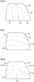
Fig. 6 is a plan view of the sole schematically showing a modified example of the recessed portion. -
Fig. 7 is a plan view of the sole schematically showing a modified example of the recessed portion. -
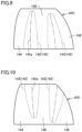
Fig. 8 is a plan view of the sole schematically showing a modified example of the recessed portion. -
Fig. 9 is a plan view of the sole schematically showing a modified example of the recessed portion. -
Fig. 10 is a plan view of the sole schematically showing a modified example of the recessed portion. - An embodiment of the present disclosure will be described with reference to the drawings. In the drawings hereinafter referred to, the same or corresponding members are denoted by the same reference numerals. In the following description, terms such as a foot length direction, a foot width direction, a front side, and a rear side are used. Terms indicating these directions indicate directions as viewed from a viewpoint of a wearer wearing a shoe 1 placed on a flat surface P (see
Fig. 1 ) such as the ground. For example, the front side refers to a toe side and the rear side refers to a heel side. In addition, an inner side or an inner foot side refers to a side of the first toe (thumb) of the foot in the foot width direction, and an outer side or an outer foot side refers to a side of the fifth toe of the foot in the foot width direction. -
Fig. 1 is a cross-sectional view schematically illustrating a shoe in one embodiment of the present disclosure.Fig. 2 is a plan view of a sole.Fig. 2 shows a sole 10 for the right foot, but the sole 10 is also applicable to the left foot. In this case, the sole for the left foot is in a shape symmetrical with or substantially similar to the sole for the right foot. - The shoe 1 in the present embodiment is suitable, for example, for running, but can also be applicable to other sports shoes or walking shoes, and the use of the shoe 1 is not limited.
- As illustrated in
Fig. 1 , the shoe 1 includes the sole 10 and an upper 20. - The upper 20 is connected to the sole 10. The upper 20 and the sole 10 provide an accommodation space for a wearer's foot. The upper 20 covers an upper surface of the wearer's foot.
- The sole 10 constitutes a part of the shoe 1. The sole 10 is connected to a lower portion of the upper 20. The sole 10 is connected to the upper 20 by adhesion, for example. As shown in
Fig. 1 , the sole 10 includes amidsole 100, anoutsole 200, and aplate 300. - The
midsole 100 has a cushioning function at the time of landing, a repulsive function at the time of taking off, and the like. Themidsole 100 is preferably made of resin, rubber, or the like having an appropriate strength and excellent buffering property. Themidsole 100 is made of, for example, a resin foam. Examples of the resin constituting themidsole 100 include a polyamide-based thermoplastic elastomer (TPA, TPAE), a thermoplastic polyurethane (TPU), a polyester-based thermoplastic elastomer (TPEE), and an ethylene-vinyl acetate copolymer (EVA). As illustrated inFig. 1 , themidsole 100 has anupper connection surface 100S to which the upper 20 is connected. - As illustrated in
Fig. 1 , themidsole 100 includes atoe support portion 110, amidfoot support portion 120, arearfoot support portion 130, and an interveningportion 140. - The
toe support portion 110 is a portion that supports a toe of the wearer's foot. Thetoe support portion 110 is a portion of themidsole 100 between a front end portion of theupper connection surface 100S of themidsole 100 in the foot length direction and a position of 5% of a total length L10 of theupper connection surface 100S in the foot length direction toward the rear side from the front end portion of theupper connection surface 100S. - Here, the foot length direction is a direction parallel to a shoe center SC (see
Fig. 2 ). The shoe center SC is not limited to the center line of the shoe 1, and may be a line that overlaps a straight line passing through the center of the calcaneus of the standard wearer of the shoe 1 and a portion between the first toe and the second toe, and the thickness direction of the sole 10. - The
midfoot support portion 120 is a portion that supports a midfoot portion of the wearer's foot. Themidfoot support portion 120 is a portion of themidsole 100 between a position of 30% of the total length L10 of theupper connection surface 100S toward the rear side from the front end portion of theupper connection surface 100S in the foot length direction and a position of 60% of the total length L10 of theupper connection surface 100S in the foot length direction toward the rear side from the front end portion of theupper connection surface 100S in the foot length direction. - The
rearfoot support portion 130 is a portion that supports a rearfoot portion of the wearer's foot. Therearfoot support portion 130 is a portion of themidsole 100 between a position of 60% of the total length L10 of theupper connection surface 100S in the foot length direction toward the rear side from the front end portion of theupper connection surface 100S in the foot length direction and a rear end portion of theupper connection surface 100S in the foot length direction. - The intervening
portion 140 is a portion interposed between thetoe support portion 110 and themidfoot support portion 120. The interveningportion 140 includes an overlappingportion 145 that overlaps an MP joint of the wearer's foot in the thickness direction of the sole 10. - The
outsole 200 is connected to a lower surface of themidsole 100. Theoutsole 200 is made of rubber, resin, or the like. Theoutsole 200 may roughly cover the entire lower surface of themidsole 100, or may cover only a part of the lower surface of themidsole 100. - The
plate 300 is disposed within themidsole 100. In the present embodiment, as shown inFig. 1 , themidsole 100 has alower midsole 101 and anupper midsole 102, and theplate 300 is disposed between thelower midsole 101 and theupper midsole 102. - The
plate 300 has a shape extending from thetoe support portion 110 to themidfoot support portion 120 in the foot length direction. In the present embodiment, as shown inFig. 1 , theplate 300 has a shape extending from thetoe support portion 110 to therearfoot support portion 130. - The flexural rigidity of the
plate 300 is larger than a flexural rigidity of themidsole 100. Theplate 300 has a function of increasing the flexural rigidity of the sole 10, a function of uniformly applying a load to portions of themidsole 100 located below the plate 300 (thelower midsole 101 in the present embodiment), and the like. Theplate 300 is made of a fiber-reinforced resin or a non-fiber-reinforced resin. Examples of fiber used for the fiber-reinforced resin include carbon fiber, glass fiber, aramid fiber, Dyneema fiber (registered trademark), Zylon fiber (registered trademark), and boron fiber. In the present embodiment, carbon fibers are used as the fibers. - As shown in
Figs. 1 ,3, and 4 , the sole 10 has atoe contact surface 11 and amidfoot contact surface 12. - The
toe contact surface 11 overlaps thetoe support portion 110 in the thickness direction and constitutes a contact portion. Thetoe contact surface 11 has a shape curved to protrude toward the flat surface P in a state where the sole 10 is placed on the flat surface P. In the present embodiment, thetoe contact surface 11 is configured by a lower surface of theoutsole 200. However, theoutsole 200 may not be provided on a lower surface of thetoe support portion 110, and thetoe contact surface 11 may be configured by the lower surface of thetoe support portion 110. - The
midfoot contact surface 12 overlaps themidfoot support portion 120 in the thickness direction and constitutes the contact portion. Themidfoot contact surface 12 has a shape curved to protrude toward the flat surface P in a state where the sole 10 is placed on the flat surface P. In the present embodiment, themidfoot contact surface 12 is configured by the lower surface of theoutsole 200. However, theoutsole 200 may not be provided on a lower surface of themidfoot support portion 120, and themidfoot contact surface 12 may be configured by the lower surface of themidfoot support portion 120. - As illustrated in
Figs. 1 to 3 , the interveningportion 140 includes a recessedportion 142, an inner connectingportion 144, and an outer connectingportion 146. InFig. 2 , the recessedportion 142 is indicated by a broken line, and aboundary 201 between theoutsole 200 and the recessedportion 142 is indicated by a two-dot chain line. - The recessed
portion 142 has a shape recessed toward a side of the wearer's foot from an imaginary curved surface IS connecting thetoe contact surface 11 and themidfoot contact surface 12. The recessedportion 142 is disposed in a central portion in the foot width direction. As illustrated inFigs. 1 and3 , the recessedportion 142 is disposed in thelower midsole 101. The recessedportion 142 may or may not be covered with theoutsole 200. When the recessedportion 142 is covered with theoutsole 200, the lower surface of theoutsole 200 is positioned closer to the side of the wearer's foot than to the imaginary curved surface IS. - The inner connecting
portion 144 is disposed inside the recessedportion 142 in the foot width direction (left side inFig. 3 ). The inner connectingportion 144 connects thetoe support portion 110 and themidfoot support portion 120. As shown inFig. 3 , the sole 10 has aninner contact surface 14a that overlaps the inner connectingportion 144 in the thickness direction and constitutes the contact portion. Theinner contact surface 14a matches the imaginary curved surface IS. In the present embodiment, theinner contact surface 14a is configured by the lower surface of theoutsole 200. However, theoutsole 200 disposed below the inner connectingportion 144 may be omitted, and theinner contact surface 14a may be configured by a lower surface of the inner connectingportion 144. - The outer connecting
portion 146 is provided outside the recessedportion 142 in the foot width direction (right side inFig. 3 ). The outer connectingportion 146 connects thetoe support portion 110 and themidfoot support portion 120. As shown inFig. 3 , the sole 10 has anouter contact surface 14b that overlaps the outer connectingportion 146 in the thickness direction and constitutes the contact portion. Theouter contact surface 14b matches the imaginary curved surface IS. In the present embodiment, theouter contact surface 14b is configured by the lower surface of theoutsole 200. However, theoutsole 200 disposed below the outer connectingportion 146 may be omitted, and theouter contact surface 14b may be configured by a lower surface of the outer connectingportion 146. - As illustrated in
Fig. 4 , a length T11 between the imaginary curved surface IS and the recessedportion 142 is greater than or equal to 13% and less than or equal to 50% of a thickness T12 of a portion of the interveningportion 140 where the recessedportion 142 is provided. - An area of the recessed
portion 142 in plan view (the area of the recessedportion 142 indicated by a broken line inFig. 2 ) is greater than or equal to 35% and less than or equal to 50% of an area of a front side region AR1 in plan view (the area of a hatched region inFig. 2 ). The front side region AR1 is a part of themidsole 100. The front side region AR1 is an area surrounded by a front line FL and a rear line RL. - The front line FL is a line passing through a first portion P1 that is located on the shoe center SC and at a position of a first length L11 from the front end portion of the
upper connection surface 100S toward the rear side in the foot length direction, and being orthogonal to the shoe center SC. The first length L11 is 5% of the total length L10 of theupper connection surface 100S. - The rear line RL is a line that is located on the shoe center SC, passes through a second portion P2 located at a position of a second length L12 from the front end portion of the
upper connection surface 100S of themidsole 100 toward the rear side in the foot length direction, and is orthogonal to the shoe center SC. The second length L12 is 30% of the total length L10 of theupper connection surface 100S. - As illustrated in
Fig. 2 , the front end of the recessedportion 142 in the foot length direction is positioned on the rear side of the front line FL, and the rear end of the recessedportion 142 in the foot length direction is positioned on the front side of the rear line RL. - The recessed
portion 142 is configured by a single upward convex surface (hereinafter, referred to as "upwardconvex surface 142") having a shape protruding from the imaginary curved surface IS toward the wearer's foot. The upwardconvex surface 142 has a shape curved to protrude toward the wearer's foot from the imaginary curved surface IS. The upwardconvex surface 142 includes atop portion 142a. The length T11 means a dimension between the imaginary curved surface IS and thetop portion 142a. InFig. 2 , thetop portion 142a is indicated by a one-dot chain line. - As illustrated in
Fig. 3 , the upwardconvex surface 142 has a central convex surface a1, an inner convex surface a2, and an outer convex surface a3. - The central convex surface a1 includes the
top portion 142a. As illustrated inFig. 1 , thetop portion 142a is provided on the front side of the overlappingportion 145 in the foot length direction. At least a part of thetop portion 142a is provided in a thenar front region AR2 (seeFig. 2 ) of themidsole 100. InFig. 2 , the thenar front region AR2 is indicated by a dot pattern. - The thenar front region AR2 is a region that overlaps a portion on the front side of the thumb MP joint of the standard wearer's foot of the shoe 1 in the thickness direction. The thenar front region AR2 is a region surrounded by a third portion P3, a fourth portion P4, a fifth portion P5 and a sixth portion P6.
- The third portion P3 is a portion located on the shoe center SC and at 13% of the total length L10 of the
upper connection surface 100S from the front end portion of theupper connection surface 100S toward the rear side in the foot length direction. - The fourth portion P4 is a portion located on the shoe center SC and at 18% of the total length L10 of the
upper connection surface 100S from the front end portion of theupper connection surface 100S toward the rear side in the foot length direction. - The fifth portion P5 is an intersection between a straight line orthogonal to the shoe center SC and passing through the third portion P3 and an end portion on the medial foot side of the
midsole 100 in the foot width direction. - The sixth portion P6 is an intersection between a straight line orthogonal to the shoe center SC and passing through the fourth portion P4 and an end portion on the medial foot side of the
midsole 100 in the foot width direction. - The inner convex surface a2 connects the central convex surface a1 and the
inner contact surface 14a. The inner convex surface a2 has a shape inclined to approach the imaginary curved surface IS gradually as being separated from the central convex surface a1 in the foot width direction. In the present embodiment, the inner convex surface a2 includes thetop portion 142a. - The outer convex surface a3 connects the central convex surface a1 and the
outer contact surface 14b. The outer convex surface a3 has a shape inclined to approach the imaginary curved surface IS gradually as being separated from the central convex surface a1 in the foot width direction. In the present embodiment, the outer convex surface a3 includes thetop portion 142a. - Each of the inner convex surface a2 and the outer convex surface a3 may be substantially orthogonal to the imaginary curved surface IS. In this case, the
top portion 142a may be disposed only on the central convex surface a1. - Next, changes in the shapes of the intervening
portion 140 from the time of landing to the time of taking off will be described with reference toFig. 5 . - From the time of landing to the time before taking off, a large load does not act on the intervening
portion 140 from the MP joint of the wearer's foot. On the other hand, at the time of taking off, a large load acts on the interveningportion 140 from the MP joint of the wearer's foot. Therefore, a particularly large compressive load acts on a portion around the recessedportion 142 of themidsole 100. - In the present embodiment, the length T11 between the imaginary curved surface IS and the recessed
portion 142 is greater than or equal to 13% of the thickness T12 of the portion of the interveningportion 140 where the recessedportion 142 is provided, and the area of the recessedportion 142 in the plan view is greater than or equal to 35% of the area of the front side region AR1 in the plan view. Therefore, at the time of taking off, the portion of themidsole 100 around the recessedportion 142 is mainly compressed and deformed relatively largely while the grounding of the recessedportion 142 is suppressed. As a result, a decrease in the angle of the ankle joint of the wearer at the time of taking off is suppressed, and thus a change in the angle of the ankle joint from the time of landing to the time of taking off is reduced. Therefore, a load on the foot during traveling or the like is reduced. - In addition, since the length T11 is less than or equal to 50% of the thickness T12, the flexural rigidity of the
midsole 100 necessary for traveling is effectively secured. On the other hand, since the flexural rigidity of the sole 10 is lowered by providing the recessedportion 142 as compared with the case where the recessedportion 142 is not provided, the cushioning property at the time of landing is secured and the compressive load is suppressed from becoming locally too high in the case of landing from the lateral foot side or the medial foot side. - Furthermore, since the area of the recessed
portion 142 in plan view is less than or equal to 50% of the area of the front side region AR1 in plan view, stability at the time of taking off is effectively secured. - In addition, since the
plate 300 is positioned on the recessedportion 142, the load acting on the portion of themidsole 100 around the recessedportion 142 through theplate 300 is equalized at the time of taking off. As a result, a range of deformation of the portion of themidsole 100 around the recessedportion 142 becomes large as compared with the case where theplate 300 is not provided. Even when a large load acts on the sole 10, the bottom touch feeling felt by the wearer is reduced. Theplate 300 improves the stability of the foot portion at the time of landing and taking off, and since theplate 300 is across the recessedportion 142 in the foot length direction, the wearer is less likely to feel a local change in hardness around the recessedportion 142. - Hereinafter, modified examples of the above embodiment will be described with reference to
Figs. 6 to 10 . - As illustrated in
Fig. 6 , the recessedportion 142 may be provided in a shape extending long in the foot length direction. In this case, thetop portion 142a also has a shape extending in the foot length direction. The front end of the recessedportion 142 in the foot length direction is positioned on the rear side of the front line FL, and the rear end of the recessedportion 142 in the foot length direction is positioned on the rear line RL. - As illustrated in
Fig. 7 , the recessedportion 142 may have a shape extending from an inner end portion to an outer end portion in the foot width direction. In this case, thetop portion 142a also has a shape extending from an inner end portion to an outer end portion in the foot width direction. It is desirable that a curvature of thetop portion 142a is close to a curvature of the MP joint of the wearer's foot. - The intervening
portion 140 includes afront intervening portion 147 disposed on the front side of the recessedportion 142 in the foot length direction and arear intervening portion 148 disposed on the rear side of the recessedportion 142 in the foot length direction. - The contact surface provided at a position overlapping each of the
front intervening portion 147 and therear intervening portion 148 in the sole 10 matches the imaginary curved surface IS. - In this aspect, transition to a take-off phase from grounding is facilitated.
- As illustrated in
Fig. 8 , the recessedportion 142 may have an inner recessed portion a4 provided on the inner side in the foot width direction and an outer recessed portion a5 formed on the outer side in the foot width direction. - The intervening
portion 140 has a central connectingportion 149 provided between the inner recessed portion a4 and the outer recessed portion a5. The central connectingportion 149 connects thefront intervening portion 147 and therear intervening portion 148. - The contact surface provided at a position overlapping each of the
front intervening portion 147, therear intervening portion 148, and the central connectingportion 149 in the sole 10 matches the imaginary curved surface IS. - In this aspect, transition to a take-off phase from grounding is facilitated.
- As illustrated in
Figs. 9 and 10 , the recessedportion 142 may have a pair ofconcave portions 143 provided at positions separated from each other in the foot width direction. Each of theconcave portions 143 has a shape extending long in the foot length direction. In the example illustrated inFig. 9 , the front end of each of theconcave portions 143 in the foot length direction is positioned on the rear side of the front line FL, and the rear end of each of theconcave portions 143 in the foot length direction is positioned on the rear line RL. In the example illustrated inFig. 10 , the front end of theconcave portion 143 disposed inside in the foot length direction matches the front line FL, the front end of theconcave portion 143 provided outside in the foot length direction matches the outside line in the foot width direction of the front line FL or the front side region AR1, and the rear end of each of theconcave portions 143 in the foot length direction is positioned on the front side of the rear line RL. - The intervening
portion 140 includes the inner connectingportion 144, the outer connectingportion 146, and the central connectingportion 149. The inner connectingportion 144 is disposed inside the pair ofconcave portions 143 in the foot width direction, and connects thetoe support portion 110 and themidfoot support portion 120. The outer connectingportion 146 is disposed outside the pair ofconcave portions 143 in the foot width direction, and connects thetoe support portion 110 and themidfoot support portion 120. The central connectingportion 149 is disposed between the pair ofconcave portions 143, and connects thetoe support portion 110 and themidfoot support portion 120. - The contact surface provided at a position overlapping each of the inner connecting
portion 144, the outer connectingportion 146, and the central connectingportion 149 in the sole 10 matches the imaginary curved surface IS. - The recessed
portion 142 may include, for example, a plurality of through holes (not illustrated) penetrating thelower midsole 101 in the thickness direction of thelower midsole 101. In this case, the contact surface of the sole 10 provided at a position overlapping the recessedportion 142 in the thickness direction may match the imaginary curved surface IS. - It is understood by those skilled in the art that the exemplary embodiment described above is a specific example of the following aspects.
- A sole constituting a part of a shoe,
- the sole including
- a midsole that is configured to support a wearer's foot, in which
- the midsole includes:
- a toe support portion that is configured to support a toe of the wearer's foot;
- a midfoot support portion that is configured to support a midfoot portion of the wearer's foot; and
- an intervening portion interposed between the toe support portion and the midfoot support portion,
- the sole includes:
- a toe contact surface that overlaps the toe support portion in a thickness direction of the sole and constitutes a contact surface; and
- a midfoot contact surface that overlaps the midfoot support portion in the thickness direction and constitutes a contact surface,
- the intervening portion includes a recessed portion having a shape recessed toward the wearer's foot from an imaginary curved surface connecting the toe contact surface and the midfoot contact surface,
- a length between the imaginary curved surface and the recessed portion is greater than or equal to 13% and less than or equal to 50% of a thickness of a portion of the intervening portion where the recessed portion is provided,
- the midsole has a front side region surrounded by a front line and a rear line, the front line passing through a first portion that is located on a shoe center and at 5% of a total length of the midsole from a front end portion of the midsole toward a rear side in a foot length direction of the sole, and being orthogonal to the shoe center, and the rear line passing through a second portion that is located on the shoe center and at 30% of the total length of the midsole from the front end portion toward the rear side in the foot length direction, and being orthogonal to the shoe center, and
- an area of the recessed portion in plan view is greater than or equal to 35% and less than or equal to 50% of an area of the front side region in plan view.
- Generally, at the time of taking off in a running motion or the like, a large load acts on the sole from a front portion of the MP joint of the wearer's foot. In this sole, the intervening portion interposed between the toe support portion and the midfoot support portion has the recessed portion, the length between the imaginary curved surface and the recessed portion is greater than or equal to 13% of the thickness of the portion of the intervening portion where the recessed portion is provided, and the area of the recessed portion in plan view is greater than or equal to 35% of the area of the front side region in plan view. Therefore, at the time of taking off, the portion of the midsole around the recessed portion is mainly compressed and deformed relatively largely while grounding of the recessed portion is suppressed. As a result, a decrease in the angle of the ankle joint of the wearer at the time of taking off is suppressed, and thus a change in the angle of the ankle joint from the time of landing to the time of taking off is reduced. Therefore, a load on the foot during traveling or the like is reduced.
- In addition, since the length between the imaginary curved surface and the recessed portion is less than or equal to 50% of the thickness of the portion of the intervening portion where the recessed portion is provided, the flexural rigidity of the
midsole 100 necessary for traveling is effectively secured. Furthermore, since the area of the recessed portion in plan view is less than or equal to 50% of the area of the front side region in plan view, stability at the time of taking off is effectively secured. - The sole according to the first aspect, in which the recessed portion is constituted by a single upward convex surface having a shape protruding from the imaginary curved surface toward the wearer's foot.
- The sole according to the second aspect, in which
- the upward convex surface has a shape curved to protrude toward the wearer's foot from the imaginary curved surface, and
- the upward convex surface has a top portion.
- The sole according to the third aspect, in which
- the midsole includes a thenar front region surrounded by a third portion, a fourth portion, a fifth portion, and a sixth portion, the third portion being located on the shoe center and at 13% of the total length of the midsole from the front end portion toward the rear side in the foot length direction, the fourth portion being located on the shoe center and at 18% of the total length of the midsole from the front end portion toward the rear side in the foot length direction, the fifth portion being an intersection between a straight line orthogonal to the shoe center and passing through the third portion and an end portion of the midsole on a medial foot side in a foot width direction of the sole, and the sixth portion being an intersection between a straight line orthogonal to the shoe center and passing through the fourth portion and an end portion of the midsole on the medial foot side in the foot width direction, and
- at least a part of the top portion is disposed in the thenar front region.
- In this aspect, since at least a part of the top portion is provided in the thenar front region where a relatively large compressive load acts at the time of taking off, an angular change of the ankle joint from the time of landing to the time of taking off is further reduced.
- The sole according to the third aspect or the fourth aspect, in which
- the intervening portion includes an overlapping portion that is configured to overlap an MP joint of the wearer's foot in the thickness direction of the sole, and
- the top portion is disposed on a front side of the overlapping portion in the foot length direction.
- The sole according to any one of the first to the fifth aspects, in which
- the recessed portion is disposed in a central portion in a foot width direction of the sole,
- the intervening portion further includes:
- an inner connecting portion disposed inside the recessed portion in the foot width direction and connecting the toe support portion and the midfoot support portion; and
- an outer connecting portion disposed outside the recessed portion in the foot width direction and connecting the toe support portion and the midfoot support portion, and
- the sole includes a contact surface that overlaps each of the inner connecting portion and the outer connecting portion in the thickness direction, and matches the imaginary curved surface.
- In this aspect, transition to the take-off phase is facilitated by load movement while improving a shock absorbing property and stability at the time of landing.
- The sole according to the sixth aspect, in which
the upward convex surface includes: - a central convex surface including the top portion;
- an inner convex surface connecting the central convex surface and the contact surface disposed below the inner connecting portion; and
- an outer convex surface connecting the central convex surface and the contact surface disposed below the outer connecting portion, and
- each of the inner convex surface and the outer convex surface has a shape inclined to approach the imaginary curved surface gradually as being separated from the central convex surface in the foot width direction.
- In this aspect, the shock absorbing property and the stability at the time of landing are further improved.
- The sole according to any one of the first to the fifth aspects, in which the recessed portion has a shape extending from an inner end portion to an outer end portion in a foot width direction of the sole.
- In this aspect, transition to a take-off phase from grounding is facilitated.
- The sole according to any one of the first to the fifth aspects, in which
- the recessed portion includes a pair of concave portions disposed at positions separated from each other in a foot width direction of the sole,
- each of the pair of concave portions has a shape extending long in the foot length direction,
- the intervening portion includes:
- a central connecting portion disposed between the pair of concave portions and connecting the toe support portion and the midfoot support portion;
- an inner connecting portion disposed inside the pair of concave portions in the foot width direction and connecting the toe support portion and the midfoot support portion; and
- an outer connecting portion disposed outside the pair of concave portions in the foot width direction and connecting the toe support portion and the midfoot support portion, and
- the sole includes a contact surface that overlaps each of the central connecting portion, the inner connecting portion, and the outer connecting portion in the thickness direction, and matches the imaginary curved surface.
- The sole according to any one of the first to the ninth aspects, further including a plate arranged inside the midsole and having a flexural rigidity greater than a flexural rigidity of the midsole, in which
the plate is arranged on the recessed portion and has a shape crossing over the recessed portion in the foot length direction. - In this aspect, since the plate is positioned on the recessed portion, the load acting on the portion of the midsole around the recessed portion through the plate is equalized at the time of taking off. As a result, a range of deformation of the portion of the midsole around the recessed portion becomes large as compared with the case where the plate is not provided. Even when a large load acts on the sole, the bottom touch feeling felt by the wearer is reduced. Further, the plate improves the stability of the foot portion at the time of landing and taking off, and since the plate is across the recessed portion in the foot length direction, the wearer is less likely to feel a local change in hardness around the recessed portion.
- A shoe including:
- the sole according to any one of the first to the tenth aspects; and
- an upper connected to the sole and providing, together with the sole, an accommodation space for the wearer's foot.
- The sole according to the third aspect, wherein the top portion includes a ridge extending in the foot width direction of the shoe or in the foot length direction of the shoe.
- Although the present invention has been described and illustrated, it is understood that the embodiment disclosed herein is by way of illustration and example only and is not to be taken by way of limitation. The scope of the present invention is interpreted by the terms of the appended claims, and it is intended that meanings equivalent to the claims and all modifications within the scope are included.
Claims (13)
- A sole (10) constituting a part of a shoe,the sole comprisinga midsole (100) that is configured to support a wearer's foot, whereinthe midsole includes:a toe support portion (110) that is configured to support a toe of the wearer's foot;a midfoot support portion (120) that is configured to support a midfoot portion of the wearer's foot; andan intervening portion (140) interposed between the toe support portion and the midfoot support portion,the sole includes:a toe contact surface (11) that overlaps the toe support portion in a thickness direction of the sole and constitutes a contact surface; anda midfoot contact surface (12) that overlaps the midfoot support portion in the thickness direction and constitutes a contact surface,the intervening portion includes a recessed portion (142) having a shape recessed toward the wearer's foot from an imaginary curved surface (IS) connecting the toe contact surface and the midfoot contact surface,a length between the imaginary curved surface and the recessed portion is greater than or equal to 13% and less than or equal to 50% of a thickness of a portion of the intervening portion where the recessed portion is provided,the midsole (100) has a front side region (AR1) surrounded by a front line (FL) and a rear line (RL), the front line passing through a first portion (P1) that is located on a shoe center (SC) and at 5% of a total length of the midsole from a front end portion of the midsole toward a rear side in a foot length direction of the sole, and being orthogonal to the shoe center, and the rear line passing through a second portion (P2) that is located on the shoe center and at 30% of the total length of the midsole from the front end portion toward the rear side in the foot length direction, and being orthogonal to the shoe center, andan area of the recessed portion in plan view is greater than or equal to 35% and less than or equal to 50% of an area of the front side region in plan view.
- The sole according to claim 1, wherein the recessed portion (142) is constituted by a single upward convex surface having a shape protruding from the imaginary curved surface toward the wearer's foot.
- The sole according to claim 2, whereinthe upward convex surface (142) has a shape curved to protrude toward the wearer's foot from the imaginary curved surface, andthe upward convex surface has a top portion (142a).
- The sole according to claim 3, whereinthe midsole includes a thenar front region (AR2) surrounded by a third portion (P3), a fourth portion (P4), a fifth portion (P5), and a sixth portion (P6), the third portion being located on the shoe center and at 13% of the total length of the midsole from the front end portion toward the rear side in the foot length direction, the fourth portion being located on the shoe center and at 18% of the total length of the midsole from the front end portion toward the rear side in the foot length direction, the fifth portion being an intersection between a straight line orthogonal to the shoe center and passing through the third portion and an end portion of the midsole on a medial foot side in a foot width direction of the sole, and the sixth portion being an intersection between a straight line orthogonal to the shoe center and passing through the fourth portion and an end portion of the midsole on the medial foot side in the foot width direction, andat least a part of the top portion is disposed in the thenar front region.
- The sole according to claim 3 or 4, whereinthe intervening portion (140) includes an overlapping portion (145) that is configured to overlap an MP joint of the wearer's foot in the thickness direction of the sole, andthe top portion is disposed on a front side of the overlapping portion in the foot length direction.
- The sole according to any preceding claim, whereinthe recessed portion (142) is disposed in a central portion in a foot width direction of the sole,the intervening portion further includes:an inner connecting portion (144) disposed inside the recessed portion in the foot width direction and connecting the toe support portion and the midfoot support portion; andan outer connecting portion (146) disposed outside the recessed portion in the foot width direction and connecting the toe support portion and the midfoot support portion, andthe sole includes a contact surface that overlaps each of the inner connecting portion and the outer connecting portion in the thickness direction, and matches the imaginary curved surface.
- The sole according to claim 6 as dependent on claim 3, wherein
the upward convex surface (142) includes:a central convex surface (a1) including the top portion;an inner convex surface (a2) connecting the central convex surface and the contact surface disposed below the inner connecting portion; andan outer convex surface (a3) connecting the central convex surface and the contact surface disposed below the outer connecting portion, andeach of the inner convex surface and the outer convex surface has a shape inclined to approach the imaginary curved surface gradually as being separated from the central convex surface in the foot width direction. - The sole according to any of claims 1 to 5, whereinthe recessed portion (142) is disposed in a central portion in a foot width direction of the sole,the intervening portion further includes:an inner connecting portion (144) disposed inside the recessed portion in the foot width direction and connecting the toe support portion and the midfoot support portion; andan outer connecting portion (146) disposed outside the recessed portion in the foot width direction and connecting the toe support portion and the midfoot support portion, andthe sole includes a contact surface that overlaps each of the inner connecting portion and the outer connecting portion in the thickness direction, and matches the imaginary curved surface.
- The sole according to any of claims 1 to 5, wherein the recessed portion has a shape extending from an inner end portion to an outer end portion in a foot width direction of the sole.
- The sole according to any of claims 1 to 5, whereinthe recessed portion includes a pair of concave portions (143) disposed at positions separated from each other in a foot width direction of the sole,each of the pair of concave portions has a shape extending long in the foot length direction,the intervening portion includes:a central connecting portion (149) disposed between the pair of concave portions and connecting the toe support portion and the midfoot support portion;an inner connecting portion (144) disposed inside the pair of concave portions in the foot width direction and connecting the toe support portion and the midfoot support portion; andan outer connecting portion (146) disposed outside the pair of concave portions in the foot width direction and connecting the toe support portion and the midfoot support portion, andthe sole includes a contact surface that overlaps each of the central connecting portion, the inner connecting portion, and the outer connecting portion in the thickness direction, and matches the imaginary curved surface.
- The sole according to any preceding claim, further comprising a plate (300) arranged inside the midsole and having a flexural rigidity greater than a flexural rigidity of the midsole, wherein
the plate is arranged on the recessed portion and has a shape crossing over the recessed portion in the foot length direction. - The sole (1) according to claim 3, wherein the top portion (142a) includes a ridge extending in the foot width direction of the shoe or in the foot length direction of the shoe.
- A shoe (1) comprising:the sole (10) according to any one of claims 1 to 12; andan upper (20) connected to the sole and providing, together with the sole, an accommodation space for the wearer's foot.
Applications Claiming Priority (1)
| Application Number | Priority Date | Filing Date | Title |
|---|---|---|---|
| JP2023032622A JP2024124738A (en) | 2023-03-03 | 2023-03-03 | Soles and shoes |
Publications (2)
| Publication Number | Publication Date |
|---|---|
| EP4424196A1 true EP4424196A1 (en) | 2024-09-04 |
| EP4424196B1 EP4424196B1 (en) | 2026-04-01 |
Family
ID=90105348
Family Applications (1)
| Application Number | Title | Priority Date | Filing Date |
|---|---|---|---|
| EP24160313.3A Active EP4424196B1 (en) | 2023-03-03 | 2024-02-28 | Sole and shoe |
Country Status (4)
| Country | Link |
|---|---|
| US (1) | US20240292926A1 (en) |
| EP (1) | EP4424196B1 (en) |
| JP (1) | JP2024124738A (en) |
| CN (1) | CN118576026A (en) |
Families Citing this family (1)
| Publication number | Priority date | Publication date | Assignee | Title |
|---|---|---|---|---|
| US12588737B2 (en) * | 2023-05-17 | 2026-03-31 | Saucony, Inc. | Footwear sole and related method of use |
Citations (9)
| Publication number | Priority date | Publication date | Assignee | Title |
|---|---|---|---|---|
| US7555848B2 (en) * | 2003-12-23 | 2009-07-07 | Nike, Inc. | Article of footwear having a fluid-filled bladder with a reinforcing structure |
| KR100945834B1 (en) * | 2009-07-17 | 2010-03-05 | 류정현 | Shock Absorbing Sole |
| KR20100011725U (en) * | 2009-05-25 | 2010-12-03 | 정 민 임 | Shoe soles |
| US20110277351A1 (en) * | 2010-05-14 | 2011-11-17 | Jim Scoledes | Shoes for har-tru, clay and other similar granular surfaces |
| US20160037857A1 (en) * | 2014-08-06 | 2016-02-11 | Nike, Inc. | Article Of Footwear With Midsole With Arcuate Underside Cavity Insert |
| US10165825B2 (en) * | 2016-04-01 | 2019-01-01 | Nike, Inc. | Article of footwear with adaptive fit |
| US20190082781A1 (en) * | 2017-09-19 | 2019-03-21 | Mizuno Corporation | Sole Structure for a Sports Shoe |
| WO2020136916A1 (en) | 2018-12-28 | 2020-07-02 | 株式会社アシックス | Shoe sole and shoe |
| US10709198B2 (en) * | 2018-03-14 | 2020-07-14 | Mizuno Corporation | Sole structure and shoe including same |
-
2023
- 2023-03-03 JP JP2023032622A patent/JP2024124738A/en active Pending
-
2024
- 2024-02-28 EP EP24160313.3A patent/EP4424196B1/en active Active
- 2024-02-29 CN CN202410225040.XA patent/CN118576026A/en active Pending
- 2024-02-29 US US18/591,300 patent/US20240292926A1/en active Pending
Patent Citations (9)
| Publication number | Priority date | Publication date | Assignee | Title |
|---|---|---|---|---|
| US7555848B2 (en) * | 2003-12-23 | 2009-07-07 | Nike, Inc. | Article of footwear having a fluid-filled bladder with a reinforcing structure |
| KR20100011725U (en) * | 2009-05-25 | 2010-12-03 | 정 민 임 | Shoe soles |
| KR100945834B1 (en) * | 2009-07-17 | 2010-03-05 | 류정현 | Shock Absorbing Sole |
| US20110277351A1 (en) * | 2010-05-14 | 2011-11-17 | Jim Scoledes | Shoes for har-tru, clay and other similar granular surfaces |
| US20160037857A1 (en) * | 2014-08-06 | 2016-02-11 | Nike, Inc. | Article Of Footwear With Midsole With Arcuate Underside Cavity Insert |
| US10165825B2 (en) * | 2016-04-01 | 2019-01-01 | Nike, Inc. | Article of footwear with adaptive fit |
| US20190082781A1 (en) * | 2017-09-19 | 2019-03-21 | Mizuno Corporation | Sole Structure for a Sports Shoe |
| US10709198B2 (en) * | 2018-03-14 | 2020-07-14 | Mizuno Corporation | Sole structure and shoe including same |
| WO2020136916A1 (en) | 2018-12-28 | 2020-07-02 | 株式会社アシックス | Shoe sole and shoe |
Also Published As
| Publication number | Publication date |
|---|---|
| CN118576026A (en) | 2024-09-03 |
| US20240292926A1 (en) | 2024-09-05 |
| JP2024124738A (en) | 2024-09-13 |
| EP4424196B1 (en) | 2026-04-01 |
Similar Documents
| Publication | Publication Date | Title |
|---|---|---|
| US10455892B2 (en) | Sole structure for shoes and shoe with the sole structure | |
| US12490799B2 (en) | Plate, sole, and shoe | |
| US12290146B2 (en) | Sole of shoe and shoe | |
| US20200100565A1 (en) | Sole Structure for Shoe and Shoe Including the Sole Structure | |
| CN114376302B (en) | Plate, sole and shoe | |
| US6108943A (en) | Article of footwear having medial and lateral sides with differing characteristics | |
| JP7085649B2 (en) | shoes | |
| US20240215680A1 (en) | Shoe sole and shoe | |
| US20200093219A1 (en) | Sole Structure and Shoe with the Sole Structure | |
| US12279670B2 (en) | Plate, sole, and shoe | |
| JP7261817B2 (en) | shoes | |
| WO2014196387A1 (en) | Shoe sole structure | |
| EP4424196B1 (en) | Sole and shoe | |
| US11717049B2 (en) | Insole for footwear | |
| JP3403952B2 (en) | Sole structure | |
| JP7550846B2 (en) | Soles and footwear | |
| US12324485B2 (en) | Shoe | |
| EP4732702A1 (en) | Shoe |
Legal Events
| Date | Code | Title | Description |
|---|---|---|---|
| PUAI | Public reference made under article 153(3) epc to a published international application that has entered the european phase |
Free format text: ORIGINAL CODE: 0009012 |
|
| STAA | Information on the status of an ep patent application or granted ep patent |
Free format text: STATUS: THE APPLICATION HAS BEEN PUBLISHED |
|
| AK | Designated contracting states |
Kind code of ref document: A1 Designated state(s): AL AT BE BG CH CY CZ DE DK EE ES FI FR GB GR HR HU IE IS IT LI LT LU LV MC ME MK MT NL NO PL PT RO RS SE SI SK SM TR |
|
| STAA | Information on the status of an ep patent application or granted ep patent |
Free format text: STATUS: REQUEST FOR EXAMINATION WAS MADE |
|
| STAA | Information on the status of an ep patent application or granted ep patent |
Free format text: STATUS: EXAMINATION IS IN PROGRESS |
|
| 17P | Request for examination filed |
Effective date: 20250303 |
|
| 17Q | First examination report despatched |
Effective date: 20250326 |
|
| GRAP | Despatch of communication of intention to grant a patent |
Free format text: ORIGINAL CODE: EPIDOSNIGR1 |
|
| STAA | Information on the status of an ep patent application or granted ep patent |
Free format text: STATUS: GRANT OF PATENT IS INTENDED |
|
| INTG | Intention to grant announced |
Effective date: 20251121 |
|
| GRAS | Grant fee paid |
Free format text: ORIGINAL CODE: EPIDOSNIGR3 |
|
| GRAA | (expected) grant |
Free format text: ORIGINAL CODE: 0009210 |
|
| STAA | Information on the status of an ep patent application or granted ep patent |
Free format text: STATUS: THE PATENT HAS BEEN GRANTED |
|
| AK | Designated contracting states |
Kind code of ref document: B1 Designated state(s): AL AT BE BG CH CY CZ DE DK EE ES FI FR GB GR HR HU IE IS IT LI LT LU LV MC ME MK MT NL NO PL PT RO RS SE SI SK SM TR |
|
| REG | Reference to a national code |
Ref country code: CH Ref legal event code: F10 Free format text: ST27 STATUS EVENT CODE: U-0-0-F10-F00 (AS PROVIDED BY THE NATIONAL OFFICE) Effective date: 20260401 Ref country code: GB Ref legal event code: FG4D |
|
| REG | Reference to a national code |
Ref country code: DE Ref legal event code: R096 Ref document number: 602024003544 Country of ref document: DE |
|
| REG | Reference to a national code |
Ref country code: IE Ref legal event code: FG4D |