EP4422347A1 - Heating device - Google Patents
Heating device Download PDFInfo
- Publication number
- EP4422347A1 EP4422347A1 EP23158327.9A EP23158327A EP4422347A1 EP 4422347 A1 EP4422347 A1 EP 4422347A1 EP 23158327 A EP23158327 A EP 23158327A EP 4422347 A1 EP4422347 A1 EP 4422347A1
- Authority
- EP
- European Patent Office
- Prior art keywords
- positioning pin
- heating chamber
- hole
- heating
- resistor
- Prior art date
- Legal status (The legal status is an assumption and is not a legal conclusion. Google has not performed a legal analysis and makes no representation as to the accuracy of the status listed.)
- Granted
Links
Images





Classifications
-
- H—ELECTRICITY
- H05—ELECTRIC TECHNIQUES NOT OTHERWISE PROVIDED FOR
- H05B—ELECTRIC HEATING; ELECTRIC LIGHT SOURCES NOT OTHERWISE PROVIDED FOR; CIRCUIT ARRANGEMENTS FOR ELECTRIC LIGHT SOURCES, IN GENERAL
- H05B3/00—Ohmic-resistance heating
- H05B3/02—Details
- H05B3/06—Heater elements structurally combined with coupling elements or holders
-
- B—PERFORMING OPERATIONS; TRANSPORTING
- B60—VEHICLES IN GENERAL
- B60H—ARRANGEMENTS OF HEATING, COOLING, VENTILATING OR OTHER AIR-TREATING DEVICES SPECIALLY ADAPTED FOR PASSENGER OR GOODS SPACES OF VEHICLES
- B60H1/00—Heating, cooling or ventilating devices
- B60H1/22—Heating, cooling or ventilating devices the heat source being other than the propulsion plant
- B60H1/2215—Heating, cooling or ventilating devices the heat source being other than the propulsion plant the heat being derived from electric heaters
- B60H1/2221—Heating, cooling or ventilating devices the heat source being other than the propulsion plant the heat being derived from electric heaters arrangements of electric heaters for heating an intermediate liquid
-
- F—MECHANICAL ENGINEERING; LIGHTING; HEATING; WEAPONS; BLASTING
- F24—HEATING; RANGES; VENTILATING
- F24H—FLUID HEATERS, e.g. WATER OR AIR HEATERS, HAVING HEAT-GENERATING MEANS, e.g. HEAT PUMPS, IN GENERAL
- F24H1/00—Water heaters, e.g. boilers, continuous-flow heaters or water-storage heaters
- F24H1/0072—Special adaptations
- F24H1/009—Special adaptations for vehicle systems
-
- F—MECHANICAL ENGINEERING; LIGHTING; HEATING; WEAPONS; BLASTING
- F24—HEATING; RANGES; VENTILATING
- F24H—FLUID HEATERS, e.g. WATER OR AIR HEATERS, HAVING HEAT-GENERATING MEANS, e.g. HEAT PUMPS, IN GENERAL
- F24H1/00—Water heaters, e.g. boilers, continuous-flow heaters or water-storage heaters
- F24H1/10—Continuous-flow heaters, i.e. heaters in which heat is generated only while the water is flowing, e.g. with direct contact of the water with the heating medium
- F24H1/12—Continuous-flow heaters, i.e. heaters in which heat is generated only while the water is flowing, e.g. with direct contact of the water with the heating medium in which the water is kept separate from the heating medium
- F24H1/121—Continuous-flow heaters, i.e. heaters in which heat is generated only while the water is flowing, e.g. with direct contact of the water with the heating medium in which the water is kept separate from the heating medium using electric energy supply
-
- F—MECHANICAL ENGINEERING; LIGHTING; HEATING; WEAPONS; BLASTING
- F24—HEATING; RANGES; VENTILATING
- F24H—FLUID HEATERS, e.g. WATER OR AIR HEATERS, HAVING HEAT-GENERATING MEANS, e.g. HEAT PUMPS, IN GENERAL
- F24H9/00—Details
- F24H9/18—Arrangement or mounting of grates or heating means
- F24H9/1809—Arrangement or mounting of grates or heating means for water heaters
- F24H9/1818—Arrangement or mounting of electric heating means
-
- H—ELECTRICITY
- H05—ELECTRIC TECHNIQUES NOT OTHERWISE PROVIDED FOR
- H05B—ELECTRIC HEATING; ELECTRIC LIGHT SOURCES NOT OTHERWISE PROVIDED FOR; CIRCUIT ARRANGEMENTS FOR ELECTRIC LIGHT SOURCES, IN GENERAL
- H05B3/00—Ohmic-resistance heating
- H05B3/40—Heating elements having the shape of rods or tubes
- H05B3/42—Heating elements having the shape of rods or tubes non-flexible
- H05B3/48—Heating elements having the shape of rods or tubes non-flexible heating conductor embedded in insulating material
-
- B—PERFORMING OPERATIONS; TRANSPORTING
- B60—VEHICLES IN GENERAL
- B60H—ARRANGEMENTS OF HEATING, COOLING, VENTILATING OR OTHER AIR-TREATING DEVICES SPECIALLY ADAPTED FOR PASSENGER OR GOODS SPACES OF VEHICLES
- B60H1/00—Heating, cooling or ventilating devices
- B60H1/22—Heating, cooling or ventilating devices the heat source being other than the propulsion plant
- B60H2001/2268—Constructional features
- B60H2001/2278—Connectors, water supply, housing, mounting brackets
-
- H—ELECTRICITY
- H05—ELECTRIC TECHNIQUES NOT OTHERWISE PROVIDED FOR
- H05B—ELECTRIC HEATING; ELECTRIC LIGHT SOURCES NOT OTHERWISE PROVIDED FOR; CIRCUIT ARRANGEMENTS FOR ELECTRIC LIGHT SOURCES, IN GENERAL
- H05B2203/00—Aspects relating to Ohmic resistive heating covered by group H05B3/00
- H05B2203/016—Heaters using particular connecting means
-
- H—ELECTRICITY
- H05—ELECTRIC TECHNIQUES NOT OTHERWISE PROVIDED FOR
- H05B—ELECTRIC HEATING; ELECTRIC LIGHT SOURCES NOT OTHERWISE PROVIDED FOR; CIRCUIT ARRANGEMENTS FOR ELECTRIC LIGHT SOURCES, IN GENERAL
- H05B2203/00—Aspects relating to Ohmic resistive heating covered by group H05B3/00
- H05B2203/021—Heaters specially adapted for heating liquids
Definitions
- the invention relates to a heating device for heating a coolant.
- the heating device is in particular intended for a vehicle, such as an automotive vehicle, for example for a heating air of a passenger compartment of the vehicle.
- the vehicle may be an electric or hybrid vehicle.
- the vehicle may be autonomous.
- the air of the passenger compartment is generally heated by using a heat exchanger to transfer heat between a flow of air and a coolant, for example a liquid.
- a coolant for example a liquid.
- the coolant is heated by a heating device in which an electric current is circulated in at least one resistor placed in contact with the coolant, so that a temperature of the resistor increases, thereby heating the coolant.
- a heating device comprising:
- the terminal needs to be connected to the printed circuit board, so that the resistor can be controlled by electronics present on the printed circuit board.
- the connection must be positioned precisely, in order to arrive at the correct location on the printed circuit board.
- space constraints it is often not possible to use positioning pins.
- the positioning and fixing functions are carried out by the same elements, namely the pierced positioning pin of the wall and the receiving through-hole of the overmolding of the connection module, which saves space.
- the invention may also include one or more of the following optional features, in any technically possible combination.
- the wall is a removable cover covering an opening through which the resistor can be inserted into the heating chamber.
- the fixing element is a screw or a rivet or a bolt.
- the sleeve is made of steel.
- the positioning pin extends at less than 0.2 mm from the overmolding in at least one direction transverse to a longitudinal direction of the positioning pin.
- one amongst the positioning pin and the through-hole of the overmolding has a truncated cone shape, while the other has a cylindrical shape.
- the heating device further comprises a housing comprising the heating chamber and delimiting an inner space, in which the heating chamber extends.
- the printed circuit board extends in the inner space.
- a vehicle comprising a heating device according to the invention, in particular in an installation of the vehicle, for heating air of a passenger compartment of the vehicle.
- the heating device 100 comprises a housing 102 with a main body 104 and an upper cover 106 and a front cover 108.
- the heating device 100 further comprises a printed circuit board 202 extending into an inner space 204 defined by the housing 102.
- the heating device 100 further comprises a heating chamber 302 extending in the inner space 204 of the housing 102 and fixed to the housing 102, for example to its main body 104.
- the heating chamber 302 comprises two compartments 304A, 304B.
- the heating chamber 302 comprises for example front covers 402A, 402B for respectively closing openings 403A, 403B of the compartments 304A, 304B, and a connection 404 for letting coolant pass between the compartments 304A, 304B.
- the heating chamber 302 is further provided with a coolant inlet 406 for letting coolant enter and a coolant outlet 408 for letting the coolant exit.
- the coolant inlet 406 is provided in the compartment 304A, while the coolant outlet is provided in the compartment 304B. With this configuration, the coolant enters by the coolant inlet 406 in the compartment 304A, pass to the compartment 304B through the connection 404 and exits the compartment 304B by the coolant outlet 408.
- the heating device 100 further comprises at least one resistor 410A, 410B located inside the heating chamber 302 for heating the coolant.
- one resistor 410A, 410B is provided in each compartment 304A, 304B.
- the opening 403A, 403B are sized in order to allow passage of the resistors 410A, 410B, respectively.
- each resistor 410A, 410B comprises two terminals 502A, 504A, 502B, 504B for receiving electrical power. At least one of the two terminals 502A, 504A, 502B, 504B passes through a wall of the heating chamber 302. For example, both terminals 502, 504 pass through the cover 402A, 402B of the compartment 304A, 304B in which lies the resistor 410A, 410B.
- the heating device 100 comprises, for each resistor 410A, 410B, a connection module 602A, 602B for connecting at least one of the two terminals 502A, 504A, 502B, 504B of the resistor 410A, 410B to the printed circuit board 202.
- Each connection module 602A, 602B is fixed to the housing, for example to the associated cover 402A, 402B, by at least one fixing element such as a screw 604.
- the connection module 602A comprises, for each of the two terminals 502A, 504A, a lead frame 702A, 704A.
- Each lead frame 702A, 704A comprises one connection pin 706A, 708A connected to the printed circuit board 202, for example passing through a respective hole provided in the printed circuit board 202.
- Each lead frame 702A, 704A further comprises a connector 710A, 712A connected to the terminal 502A, 504A.
- each connector 710A, 712A comprises a clamp for clamping the associated terminal 502A, 504A.
- the connection module 602A further comprises an overmolding 714A around the lead frames 702A, 704A.
- the connection module 602B comprises, for each of the two terminals 502B, 504B, a lead frame 802B, 804B.
- Each lead frame 802B, 804B comprises one connection pin 806B, 808B connected to the printed circuit board 202, for example passing through a respective hole provided in the printed circuit board 202.
- Each lead frame 802B, 804B further comprises a connector 810B, 812B connected to the terminal 502B, 504B.
- each connector 810B, 812B comprises a clamp for clamping the associated terminal 502B, 504B.
- the connection module 602B further comprises an overmolding 814B around the lead frames 802B, 804B.
- fixing of the cover 402A by means of the fixating element 604 will now be described in greater detail. Fixing of cover 402B by means of the fixating elements 604 is similar.
- the cover 402A is provided with a positioning pin 902 projecting outside the heating chamber 302 and having a hole 904. More precisely, the positioning pin 902 extends along a longitudinal direction, which is the X direction in the illustrated example.
- the overmolding 714A has a positioning trough-hole 906 in which the positioning pin 902 is inserted.
- the positioning trough-hole 906 comprises a first section 908 and a second section 910 connected to each other by an inner shoulder 912, so that the first section 908 has a diameter greater than a diameter of the second section 910.
- the positioning pin 902 may then be inserted into the first section 908, the inner shoulder 912 forming a stop for the positioning pin 902.
- the positioning pin 902 extends preferably at less than 0.2 mm from the overmolding 714A, 814B in at least one direction transverse to a longitudinal direction Z of the positioning pin 902, preferably in all transverse directions.
- the transverse directions are in the plane defined by directions Y and Z.
- one amongst the positioning pin 902 and the through-hole 906 of the overmolding 714A has a truncated cone shape, while the other has a cylindrical shape.
- the positioning pin 902 has the truncated cone shape
- the first section 908 of the through-hole 906 of the overmolding has a cylindrical shape. This helps guide the insertion of the positioning pin 902 inside the through-hole 906.
- connection module 602A further comprises a sleeve 914 inserted, for example pressed-in, into the positioning through-hole 906 next to the positioning pin 902.
- the sleeve 914 is inserted into the second section 912.
- the sleeve 914 is made of steel, in order to be more rigid than the overmolding 714A.
- the fixing element i.e. the screw 604 in the described example, comprises a rod 916 and a head 918 fixed to a end of the rod 916.
- the rod 916 is successively inserted into the sleeve 914 and the hole 904 of the positioning pin 902, so that the sleeve 914 is clamped between the positioning pin 902 and the head 918.
- the housing 102 with the heating chamber 302 is obtained, with the covers 402A, 402B and the printed circuit board 202 separated.
- each resistor 410A, 410B is inserted into its respective compartment 304A, 304B trough the respective opening 403A, 403B.
- each cover 402A, 402B is fixed to the heating chamber 302 to close the associated opening 403A, 403B, while letting the terminals 502A, 504A, 502B, 504B pass trough the cover 402A, 402B.
- each connection module 602A, 602B is temporarily fixed to the associated cover 402A, 402B by inserting the positioning pin 902 of the cover 402A, 402B into the through hole 906, into its first section 908 in the described example, of the connection module 602A, 602B.
- the terminals 502A, 504A, 502B, 504B are respectively clamped by the connectors 502A, 504A, 502B, 504B.
- the fixing elements i.e. the screws 604 are installed so as to fix the connection modules 602A, 602B to the covers 402A, 402B, respectively.
- the printed circuit board 202 is fixed to the housing 102, for example by screwing, for example to the heating chamber 302, while connecting the pins 706A, 708B, 806B, 808B of the connection module 602A, 602B to the printed circuit board 202.
Landscapes
- Engineering & Computer Science (AREA)
- Physics & Mathematics (AREA)
- Thermal Sciences (AREA)
- Mechanical Engineering (AREA)
- Chemical & Material Sciences (AREA)
- Combustion & Propulsion (AREA)
- General Engineering & Computer Science (AREA)
- Air-Conditioning For Vehicles (AREA)
- Resistance Heating (AREA)
Abstract
Description
- The invention relates to a heating device for heating a coolant. The heating device is in particular intended for a vehicle, such as an automotive vehicle, for example for a heating air of a passenger compartment of the vehicle. The vehicle may be an electric or hybrid vehicle. The vehicle may be autonomous.
- The air of the passenger compartment is generally heated by using a heat exchanger to transfer heat between a flow of air and a coolant, for example a liquid. For hybrid or electric vehicles, the coolant is heated by a heating device in which an electric current is circulated in at least one resistor placed in contact with the coolant, so that a temperature of the resistor increases, thereby heating the coolant.
- In this context, it is known to use a heating device comprising:
- a heating chamber provided with a coolant inlet for letting coolant enter and a coolant outlet for letting the coolant exit;
- a resistor located inside the heating chamber for heating the coolant, the resistor comprising a terminal passing through a wall of the heating chamber; and
- a printed circuit board located outside the heating chamber for controlling the resistor.
- The terminal needs to be connected to the printed circuit board, so that the resistor can be controlled by electronics present on the printed circuit board. The connection must be positioned precisely, in order to arrive at the correct location on the printed circuit board. However, due to space constraints, it is often not possible to use positioning pins.
- It may thus be desirable to provide an object which makes it possible to overcome at least some of the aforementioned problems and constraints.
- It is therefore proposed a heating device comprising:
- a heating chamber provided with a coolant inlet for letting coolant enter and a coolant outlet for letting the coolant exit;
- a resistor located inside the heating chamber for heating the coolant, the resistor comprising a terminal passing through a wall of the heating chamber; and
- a printed circuit board located outside the heating chamber for controlling the resistor.
- a connection module comprising:
- a lead frame comprising a connection pin connected to the printed circuit board and a connector connected to the terminal of the resistor,
- an overmolding around the lead frame, the overmolding having a trough-hole in which the positioning pin is inserted, and
- a sleeve inserted into the through-hole next to the positioning pin; and
- a fixing element comprising a rod and a head, the rod being inserted into successively the sleeve and the hole of the positioning pin, so that the sleeve is clamped between the positioning pin and the head.
- Thanks to the invention, the positioning and fixing functions are carried out by the same elements, namely the pierced positioning pin of the wall and the receiving through-hole of the overmolding of the connection module, which saves space.
- The invention may also include one or more of the following optional features, in any technically possible combination.
- Optionally, the wall is a removable cover covering an opening through which the resistor can be inserted into the heating chamber.
- Also optionally, the fixing element is a screw or a rivet or a bolt.
- Also optionally, the sleeve is made of steel.
- Also optionally, inside the through-hole of the overmolding, the positioning pin extends at less than 0.2 mm from the overmolding in at least one direction transverse to a longitudinal direction of the positioning pin.
- Also optionally, one amongst the positioning pin and the through-hole of the overmolding, has a truncated cone shape, while the other has a cylindrical shape.
- Also optionally, the heating device further comprises a housing comprising the heating chamber and delimiting an inner space, in which the heating chamber extends.
- Also optionally, the printed circuit board extends in the inner space.
- It is also proposed a vehicle comprising a heating device according to the invention, in particular in an installation of the vehicle, for heating air of a passenger compartment of the vehicle.
- It is also proposed a method for connecting, in a heating device, a terminal of a resistor located in a heating chamber provided with a coolant inlet for letting coolant enter and a coolant outlet for letting the coolant exit, the terminal passing through a wall of the heating chamber, to a printed circuit board located outside the heating chamber for controlling the resistor, characterized in that the wall is provided with a positioning pin projecting outside the heating chamber and having a hole, and in that the method comprises:
- fixing a connection module to the wall by inserting a positioning pin of the wall projecting outside the heating chamber into a through-hole provided in an overmolding around a lead frame of the connection module, while connecting the terminal to a connector of the lead frame;
- inserting a rod of a fixing element into successively a sleeve located inside the through-hole and a hole of the positioning pin, so that the sleeve is clamped between the positioning pin and a head of the fixing element located at an end of the rod; and
- fixing the printed circuit board to the heating chamber, while connecting a pin of the lead frame to the printed circuit board.
- The invention will be better understood using the following description, given solely by way of example and made with reference to the accompanying drawings in which:
-
figure 1 is a three dimensional view of a heating device according to the invention, -
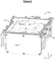
figure 2 is a three dimensional view of the heating device, with a top cover removed in order to reveal a printed circuit board, -
figure 3 is a three dimensional view of the heating device, with the printed circuit board removed in order to reveal a heating chamber, -
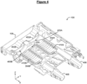
figure 4 is a three dimensional cross-sectional view of the heating device, showing resistors in the heating chamber, -
figure 5 is a three dimensional view of the heating device, with front covers removed in order to reveal terminals of the resistors passing through the heating chamber, -
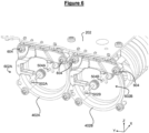
figure 6 is a three dimensional view of part of the heating device, showing connection modules for connecting the terminals of the resistors to the printed circuit board, -
figure 7 is a three dimensional view of one of the connection modules, with an overmolding shown transparent, -
figure 8 is a three dimensional view of the other of the connection modules, with an overmolding shown transparent, -
figure 9 is a cross sectional view of a fixing mechanism for fixing the connection module to the front cover, and -
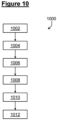
figure 10 is a block diagram illustrating steps of a method for connecting the terminals of the resistors to the printed circuit board. - Referring to
figures 1 to 9 , an example of aheating device 100 according to the invention, will now be described. - In the following description, elements of the
heating device 100 will be described with respect to an arbitrary orthogonal set of axis X, Y, Z. - Referring to
figure 1 , theheating device 100 comprises ahousing 102 with amain body 104 and anupper cover 106 and afront cover 108. - Referring to
figure 2 , theheating device 100 further comprises a printedcircuit board 202 extending into aninner space 204 defined by thehousing 102. - Referring to
figure 3 , theheating device 100 further comprises aheating chamber 302 extending in theinner space 204 of thehousing 102 and fixed to thehousing 102, for example to itsmain body 104. For example, theheating chamber 302 comprises twocompartments - Referring to
figure 4 , theheating chamber 302 comprises forexample front covers closing openings compartments connection 404 for letting coolant pass between thecompartments - The
heating chamber 302 is further provided with acoolant inlet 406 for letting coolant enter and acoolant outlet 408 for letting the coolant exit. For example, thecoolant inlet 406 is provided in thecompartment 304A, while the coolant outlet is provided in thecompartment 304B. With this configuration, the coolant enters by thecoolant inlet 406 in thecompartment 304A, pass to thecompartment 304B through theconnection 404 and exits thecompartment 304B by thecoolant outlet 408. - The
heating device 100 further comprises at least oneresistor heating chamber 302 for heating the coolant. For example, oneresistor compartment opening resistors - Referring to
figure 5 , eachresistor terminals terminals heating chamber 302. For example, both terminals 502, 504 pass through thecover compartment resistor - Referring to
figure 6 , theheating device 100 comprises, for eachresistor connection module terminals resistor circuit board 202. Eachconnection module cover screw 604. - Referring to
figure 7 , theconnection module 602A comprises, for each of the twoterminals lead frame lead frame connection pin circuit board 202, for example passing through a respective hole provided in the printedcircuit board 202. Eachlead frame connector connector connection module 602A further comprises anovermolding 714A around the lead frames 702A, 704A. - Similarly, Referring to
figure 8 , theconnection module 602B comprises, for each of the twoterminals lead frame lead frame connection pin circuit board 202, for example passing through a respective hole provided in the printedcircuit board 202. Eachlead frame connector connector connection module 602B further comprises anovermolding 814B around the lead frames 802B, 804B. - Referring to
figure 9 , fixing of thecover 402A by means of the fixatingelement 604 will now be described in greater detail. Fixing ofcover 402B by means of the fixatingelements 604 is similar. - The
cover 402A is provided with apositioning pin 902 projecting outside theheating chamber 302 and having ahole 904. More precisely, thepositioning pin 902 extends along a longitudinal direction, which is the X direction in the illustrated example. - The
overmolding 714A has a positioning trough-hole 906 in which thepositioning pin 902 is inserted. For example, the positioning trough-hole 906 comprises afirst section 908 and asecond section 910 connected to each other by aninner shoulder 912, so that thefirst section 908 has a diameter greater than a diameter of thesecond section 910. Thepositioning pin 902 may then be inserted into thefirst section 908, theinner shoulder 912 forming a stop for thepositioning pin 902. - Inside the through-
hole 906 of theovermolding 714A, thepositioning pin 902 extends preferably at less than 0.2 mm from theovermolding positioning pin 902, preferably in all transverse directions. In the illustrated example, the transverse directions are in the plane defined by directions Y and Z. - Also preferably, one amongst the
positioning pin 902 and the through-hole 906 of theovermolding 714A, has a truncated cone shape, while the other has a cylindrical shape. In the illustrated example, thepositioning pin 902 has the truncated cone shape, and thefirst section 908 of the through-hole 906 of the overmolding has a cylindrical shape. This helps guide the insertion of thepositioning pin 902 inside the through-hole 906. - The
connection module 602A further comprises asleeve 914 inserted, for example pressed-in, into the positioning through-hole 906 next to thepositioning pin 902. For example, thesleeve 914 is inserted into thesecond section 912. For example, thesleeve 914 is made of steel, in order to be more rigid than theovermolding 714A. - The fixing element, i.e. the
screw 604 in the described example, comprises arod 916 and ahead 918 fixed to a end of therod 916. Therod 916 is successively inserted into thesleeve 914 and thehole 904 of thepositioning pin 902, so that thesleeve 914 is clamped between thepositioning pin 902 and thehead 918. - Referring to
figure 10 , amethod 1000 for connecting the terminals to the circuit board will now be described. - At a
step 1002, thehousing 102 with theheating chamber 302 is obtained, with thecovers circuit board 202 separated. - At a
step 1004, eachresistor respective compartment respective opening - At a
step 1006, eachcover heating chamber 302 to close the associatedopening terminals cover - At a
step 1008, eachconnection module cover positioning pin 902 of thecover hole 906, into itsfirst section 908 in the described example, of theconnection module terminals connectors - At a
step 1010, the fixing elements, i.e. thescrews 604, are installed so as to fix theconnection modules covers - At a
step 1012, the printedcircuit board 202 is fixed to thehousing 102, for example by screwing, for example to theheating chamber 302, while connecting thepins connection module circuit board 202. - As a conclusion, it will be noted that the invention is not limited to the embodiments described above. It will indeed appear to those skilled in the art that various modifications can be made to the embodiments described above, in the light of the teaching which has just been disclosed to them.
- In the detailed presentation of the invention which is made previously, the terms used must not be interpreted as limiting the invention to the embodiments set out in the present description, but must be interpreted to include therein all the equivalents within the reach of those skilled in the art by applying their general knowledge to the implementation of the teaching which has just been disclosed to them.
Claims (10)
- Heating device (100) comprising:- a heating chamber (302) provided with a coolant inlet (406) for letting coolant enter and a coolant outlet (408) for letting the coolant exit;- a resistor (410A, 410B) located inside the heating chamber (302) for heating the coolant, the resistor (410A, 410B) comprising a terminal (502A, 504A, 502B, 504B) passing through a wall (402A, 402B) of the heating chamber (302); and- a printed circuit board (202) located outside the heating chamber (302) for controlling the resistor (410A, 410B);characterized in that the wall (402A, 402B) is provided with a positioning pin (902) projecting outside the heating chamber (302) and having a hole (904), and characterized in that it further comprises:- a connection module (602A, 602B) comprising:• a lead frame (702A, 704A, 802B, 804B) comprising a connection pin (706A, 708A, 806A, 808A) connected to the printed circuit board (202) and a connector (710A, 712A, 810B, 812B) connected to the terminal (502A, 504A, 502B, 504B) of the resistor (410A, 410B),• an overmolding (714A, 814B) around the lead frame (702A, 704A, 802B, 804B), the overmolding (714A, 814B) having a trough-hole (906) in which the positioning pin (902) is inserted, and• a sleeve (914) inserted into the through-hole (906) next to the positioning pin (902); and- a fixing element (604) comprising a rod (916) and a head (918), the rod (916) being inserted into successively the sleeve (914) and the hole (904) of the positioning pin (902), so that the sleeve (914) is clamped between the positioning pin (902) and the head (918).
- Heating device (100) according to claim 1, wherein the wall (402A, 402B) is a removable cover covering an opening (403A, 403B) through which the resistor (410A, 410B) can be inserted into the heating chamber (302).
- Heating device (100) according to claim 1 or 2, wherein the fixing element (604) is a screw or a rivet or a bolt.
- Heating device (100) according to any of claims 1 to 3, wherein the sleeve (914) is made of steel.
- Heating device (100) according to any of claims 1 to 4, wherein, inside the through-hole (906) of the overmolding (714A, 814B), the positioning pin (902) extends at less than 0.2 mm from the overmolding (714A, 814B) in at least one direction (X, Y) transverse to a longitudinal direction (Z) of the positioning pin (902).
- Heating device (100) according to any of claims 1 to 5, wherein one amongst the positioning pin (902) and the through-hole (906) of the overmolding (714A, 814B), has a truncated cone shape, while the other has a cylindrical shape.
- Heating device (100) according to any of claims 1 to 6, further comprising a housing (102) comprising the heating chamber (302) and delimiting an inner space (204), in which the heating chamber (302) extends.
- Heating device (100) according to claim 7, wherein the printed circuit board (202) extends in the inner space (204).
- Vehicle comprising a heating device (100) according to any of claims 1 to 8, in particular in an installation of the vehicle, for heating air of a passenger compartment of the vehicle.
- Method (1000) for connecting, in a heating device (100), a terminal (502A, 504A, 502B, 504B) of a resistor (410A, 410B) located in a heating chamber (302) provided with a coolant inlet (406) for letting coolant enter and a coolant outlet (408) for letting the coolant exit, the terminal (502A, 504A, 502B, 504B) passing through a wall (402A, 402B) of the heating chamber (302), to a printed circuit board (202) located outside the heating chamber (302) for controlling the resistor (410A, 410B), characterized in that the wall (402A, 402B) is provided with a positioning pin (902) projecting outside the heating chamber (302) and having a hole (904), and in that the method comprises:- fixing (1008) a connection module (602A, 602B) to the wall (402A, 402B) by inserting a positioning pin (902) of the wall (402A, 402B) projecting outside the heating chamber (302) into a through-hole (906) provided in an overmolding (714A, 814B) around a lead frame (702A, 704A, 802B, 804B) of the connection module, while connecting the terminal (502A, 504A, 502B, 504B) to a connector (502A, 504A, 502B, 504B) of the lead frame (702A, 704A, 802B, 804B);- inserting (1010) a rod (916) of a fixing element (604) into successively a sleeve (914) located inside the through-hole (906) and a hole (904) of the positioning pin (902), so that the sleeve (914) is clamped between the positioning pin (902) and a head (918) of the fixing element (604) located at an end of the rod (916); and- fixing (1012) the printed circuit board (202) to the heating chamber (302), while connecting a pin (706A, 708B, 806B, 808B) of the lead frame (702A, 704A, 802B, 804B) to the printed circuit board (202).
Priority Applications (3)
| Application Number | Priority Date | Filing Date | Title |
|---|---|---|---|
| EP23158327.9A EP4422347B1 (en) | 2023-02-23 | 2023-02-23 | Heating device |
| CN202480007411.5A CN120476668A (en) | 2023-02-23 | 2024-02-06 | Heating device |
| PCT/EP2024/052911 WO2024175353A1 (en) | 2023-02-23 | 2024-02-06 | Heating device |
Applications Claiming Priority (1)
| Application Number | Priority Date | Filing Date | Title |
|---|---|---|---|
| EP23158327.9A EP4422347B1 (en) | 2023-02-23 | 2023-02-23 | Heating device |
Publications (2)
| Publication Number | Publication Date |
|---|---|
| EP4422347A1 true EP4422347A1 (en) | 2024-08-28 |
| EP4422347B1 EP4422347B1 (en) | 2025-11-26 |
Family
ID=85381161
Family Applications (1)
| Application Number | Title | Priority Date | Filing Date |
|---|---|---|---|
| EP23158327.9A Active EP4422347B1 (en) | 2023-02-23 | 2023-02-23 | Heating device |
Country Status (3)
| Country | Link |
|---|---|
| EP (1) | EP4422347B1 (en) |
| CN (1) | CN120476668A (en) |
| WO (1) | WO2024175353A1 (en) |
Citations (4)
| Publication number | Priority date | Publication date | Assignee | Title |
|---|---|---|---|---|
| DE9306773U1 (en) * | 1993-05-05 | 1994-04-21 | Gering, Gerta, 51702 Bergneustadt | Fastening device made of plastic, in particular for circuit boards |
| EP2280232A2 (en) * | 2009-07-24 | 2011-02-02 | Balboa Water Group, Inc. | Bathing installation heater assembly |
| EP3334245A1 (en) * | 2016-12-06 | 2018-06-13 | Eberspächer catem GmbH & Co. KG | Electric heating device and ptc heating element of an electric heating device |
| EP3843502A1 (en) * | 2019-12-27 | 2021-06-30 | Eberspächer catem GmbH & Co. KG | Electric heating device |
-
2023
- 2023-02-23 EP EP23158327.9A patent/EP4422347B1/en active Active
-
2024
- 2024-02-06 WO PCT/EP2024/052911 patent/WO2024175353A1/en not_active Ceased
- 2024-02-06 CN CN202480007411.5A patent/CN120476668A/en active Pending
Patent Citations (4)
| Publication number | Priority date | Publication date | Assignee | Title |
|---|---|---|---|---|
| DE9306773U1 (en) * | 1993-05-05 | 1994-04-21 | Gering, Gerta, 51702 Bergneustadt | Fastening device made of plastic, in particular for circuit boards |
| EP2280232A2 (en) * | 2009-07-24 | 2011-02-02 | Balboa Water Group, Inc. | Bathing installation heater assembly |
| EP3334245A1 (en) * | 2016-12-06 | 2018-06-13 | Eberspächer catem GmbH & Co. KG | Electric heating device and ptc heating element of an electric heating device |
| EP3843502A1 (en) * | 2019-12-27 | 2021-06-30 | Eberspächer catem GmbH & Co. KG | Electric heating device |
Also Published As
| Publication number | Publication date |
|---|---|
| CN120476668A (en) | 2025-08-12 |
| EP4422347B1 (en) | 2025-11-26 |
| WO2024175353A1 (en) | 2024-08-29 |
Similar Documents
| Publication | Publication Date | Title |
|---|---|---|
| US11194230B2 (en) | Vehicle optical device comprising a heating element | |
| JP3298493B2 (en) | Heat exchanger for vehicle heating | |
| US6124570A (en) | Heating and air conditioning system for vehicles | |
| US6888099B1 (en) | Wind tunnel for a welding power supply housing | |
| US20080200045A1 (en) | Electric junction box | |
| EP4422347B1 (en) | Heating device | |
| JPH11263173A (en) | Electrical interconnection module for automotive instrument panel | |
| DE102019215338A1 (en) | Battery and use of such a battery | |
| US12548944B2 (en) | Cooling fluid guidance housing and electrical connector system with a cooling fluid guidance housing | |
| US20230106007A1 (en) | Drive unit of an electrical power-assisted steering system for a motor vehicle | |
| EP3621421A1 (en) | Power modules for power distribution assemblies | |
| KR101885400B1 (en) | Electric heating device, and ventilation and heating installation | |
| CN110301164B (en) | Electrical connection interface for an electrical heating device of a motor vehicle | |
| JPH0362911B2 (en) | ||
| EP0108522A1 (en) | Instrument panel for a motor car | |
| DE10339182B4 (en) | Instrument panel with integrated HVAC and electronics systems | |
| US6108905A (en) | Method and structure for assembling meter modules to vehicles | |
| US7867030B2 (en) | Electronic module comprising a shielded connector fixed to an integrated circuit card by means of a lug for fixing the shielding | |
| US4464006A (en) | Wiring system for trucks with improved firewall connection system | |
| CN115513682B (en) | Terminal Block | |
| DE4411134C2 (en) | Ignition coil for internal combustion engines | |
| US20020094714A1 (en) | Vehicle air-conditioning module | |
| US11908653B2 (en) | High voltage power distributor | |
| US20240215167A1 (en) | Transistor pin alignment assembly | |
| CN219570429U (en) | Heat radiation fan system |
Legal Events
| Date | Code | Title | Description |
|---|---|---|---|
| PUAI | Public reference made under article 153(3) epc to a published international application that has entered the european phase |
Free format text: ORIGINAL CODE: 0009012 |
|
| STAA | Information on the status of an ep patent application or granted ep patent |
Free format text: STATUS: THE APPLICATION HAS BEEN PUBLISHED |
|
| AK | Designated contracting states |
Kind code of ref document: A1 Designated state(s): AL AT BE BG CH CY CZ DE DK EE ES FI FR GB GR HR HU IE IS IT LI LT LU LV MC ME MK MT NL NO PL PT RO RS SE SI SK SM TR |
|
| STAA | Information on the status of an ep patent application or granted ep patent |
Free format text: STATUS: REQUEST FOR EXAMINATION WAS MADE |
|
| GRAP | Despatch of communication of intention to grant a patent |
Free format text: ORIGINAL CODE: EPIDOSNIGR1 |
|
| STAA | Information on the status of an ep patent application or granted ep patent |
Free format text: STATUS: GRANT OF PATENT IS INTENDED |
|
| 17P | Request for examination filed |
Effective date: 20250226 |
|
| INTG | Intention to grant announced |
Effective date: 20250402 |
|
| GRAS | Grant fee paid |
Free format text: ORIGINAL CODE: EPIDOSNIGR3 |
|
| GRAA | (expected) grant |
Free format text: ORIGINAL CODE: 0009210 |
|
| STAA | Information on the status of an ep patent application or granted ep patent |
Free format text: STATUS: THE PATENT HAS BEEN GRANTED |
|
| AK | Designated contracting states |
Kind code of ref document: B1 Designated state(s): AL AT BE BG CH CY CZ DE DK EE ES FI FR GB GR HR HU IE IS IT LI LT LU LV MC ME MK MT NL NO PL PT RO RS SE SI SK SM TR |
|
| REG | Reference to a national code |
Ref country code: CH Ref legal event code: F10 Free format text: ST27 STATUS EVENT CODE: U-0-0-F10-F00 (AS PROVIDED BY THE NATIONAL OFFICE) Effective date: 20251126 Ref country code: GB Ref legal event code: FG4D |
|
| REG | Reference to a national code |
Ref country code: IE Ref legal event code: FG4D |
|
| REG | Reference to a national code |
Ref country code: DE Ref legal event code: R096 Ref document number: 602023008861 Country of ref document: DE |
|
| REG | Reference to a national code |
Ref country code: CH Ref legal event code: W10 Free format text: ST27 STATUS EVENT CODE: U-0-0-W10-W00 (AS PROVIDED BY THE NATIONAL OFFICE) Effective date: 20260218 |
|
| RAP2 | Party data changed (patent owner data changed or rights of a patent transferred) |
Owner name: VALEO ELECTRIFICATION |
|
| REG | Reference to a national code |
Ref country code: NL Ref legal event code: MP Effective date: 20251126 |
|
| PG25 | Lapsed in a contracting state [announced via postgrant information from national office to epo] |
Ref country code: ES Free format text: LAPSE BECAUSE OF FAILURE TO SUBMIT A TRANSLATION OF THE DESCRIPTION OR TO PAY THE FEE WITHIN THE PRESCRIBED TIME-LIMIT Effective date: 20251126 |
|
| REG | Reference to a national code |
Ref country code: LT Ref legal event code: MG9D |
|
| PG25 | Lapsed in a contracting state [announced via postgrant information from national office to epo] |
Ref country code: NO Free format text: LAPSE BECAUSE OF FAILURE TO SUBMIT A TRANSLATION OF THE DESCRIPTION OR TO PAY THE FEE WITHIN THE PRESCRIBED TIME-LIMIT Effective date: 20260226 |
|
| PGFP | Annual fee paid to national office [announced via postgrant information from national office to epo] |
Ref country code: DE Payment date: 20260206 Year of fee payment: 4 |
|
| PG25 | Lapsed in a contracting state [announced via postgrant information from national office to epo] |
Ref country code: FI Free format text: LAPSE BECAUSE OF FAILURE TO SUBMIT A TRANSLATION OF THE DESCRIPTION OR TO PAY THE FEE WITHIN THE PRESCRIBED TIME-LIMIT Effective date: 20251126 Ref country code: HR Free format text: LAPSE BECAUSE OF FAILURE TO SUBMIT A TRANSLATION OF THE DESCRIPTION OR TO PAY THE FEE WITHIN THE PRESCRIBED TIME-LIMIT Effective date: 20251126 Ref country code: AT Free format text: LAPSE BECAUSE OF FAILURE TO SUBMIT A TRANSLATION OF THE DESCRIPTION OR TO PAY THE FEE WITHIN THE PRESCRIBED TIME-LIMIT Effective date: 20251126 |
|
| PGFP | Annual fee paid to national office [announced via postgrant information from national office to epo] |
Ref country code: AT Payment date: 20260301 Year of fee payment: 4 |
|
| REG | Reference to a national code |
Ref country code: AT Ref legal event code: MK05 Ref document number: 1862503 Country of ref document: AT Kind code of ref document: T Effective date: 20251126 |
|
| PG25 | Lapsed in a contracting state [announced via postgrant information from national office to epo] |
Ref country code: NL Free format text: LAPSE BECAUSE OF FAILURE TO SUBMIT A TRANSLATION OF THE DESCRIPTION OR TO PAY THE FEE WITHIN THE PRESCRIBED TIME-LIMIT Effective date: 20251126 |
|
| PG25 | Lapsed in a contracting state [announced via postgrant information from national office to epo] |
Ref country code: RS Free format text: LAPSE BECAUSE OF FAILURE TO SUBMIT A TRANSLATION OF THE DESCRIPTION OR TO PAY THE FEE WITHIN THE PRESCRIBED TIME-LIMIT Effective date: 20260226 |
|
| PG25 | Lapsed in a contracting state [announced via postgrant information from national office to epo] |
Ref country code: IS Free format text: LAPSE BECAUSE OF FAILURE TO SUBMIT A TRANSLATION OF THE DESCRIPTION OR TO PAY THE FEE WITHIN THE PRESCRIBED TIME-LIMIT Effective date: 20260326 |
|
| PG25 | Lapsed in a contracting state [announced via postgrant information from national office to epo] |
Ref country code: PT Free format text: LAPSE BECAUSE OF FAILURE TO SUBMIT A TRANSLATION OF THE DESCRIPTION OR TO PAY THE FEE WITHIN THE PRESCRIBED TIME-LIMIT Effective date: 20260326 |
|
| PG25 | Lapsed in a contracting state [announced via postgrant information from national office to epo] |
Ref country code: PL Free format text: LAPSE BECAUSE OF FAILURE TO SUBMIT A TRANSLATION OF THE DESCRIPTION OR TO PAY THE FEE WITHIN THE PRESCRIBED TIME-LIMIT Effective date: 20251126 |
|
| PG25 | Lapsed in a contracting state [announced via postgrant information from national office to epo] |
Ref country code: LV Free format text: LAPSE BECAUSE OF FAILURE TO SUBMIT A TRANSLATION OF THE DESCRIPTION OR TO PAY THE FEE WITHIN THE PRESCRIBED TIME-LIMIT Effective date: 20251126 |
|
| PG25 | Lapsed in a contracting state [announced via postgrant information from national office to epo] |
Ref country code: BG Free format text: LAPSE BECAUSE OF FAILURE TO SUBMIT A TRANSLATION OF THE DESCRIPTION OR TO PAY THE FEE WITHIN THE PRESCRIBED TIME-LIMIT Effective date: 20251126 |