EP4422190A1 - Camera holder for automotive cameras - Google Patents
Camera holder for automotive cameras Download PDFInfo
- Publication number
- EP4422190A1 EP4422190A1 EP24157201.5A EP24157201A EP4422190A1 EP 4422190 A1 EP4422190 A1 EP 4422190A1 EP 24157201 A EP24157201 A EP 24157201A EP 4422190 A1 EP4422190 A1 EP 4422190A1
- Authority
- EP
- European Patent Office
- Prior art keywords
- camera
- backside
- clip
- housings
- holder
- Prior art date
- Legal status (The legal status is an assumption and is not a legal conclusion. Google has not performed a legal analysis and makes no representation as to the accuracy of the status listed.)
- Pending
Links
Images
Classifications
-
- H—ELECTRICITY
- H04—ELECTRIC COMMUNICATION TECHNIQUE
- H04N—PICTORIAL COMMUNICATION, e.g. TELEVISION
- H04N23/00—Cameras or camera modules comprising electronic image sensors; Control thereof
- H04N23/57—Mechanical or electrical details of cameras or camera modules specially adapted for being embedded in other devices
-
- B—PERFORMING OPERATIONS; TRANSPORTING
- B60—VEHICLES IN GENERAL
- B60R—VEHICLES, VEHICLE FITTINGS, OR VEHICLE PARTS, NOT OTHERWISE PROVIDED FOR
- B60R11/00—Arrangements for holding or mounting articles, not otherwise provided for
- B60R11/04—Mounting of cameras operative during drive; Arrangement of controls thereof relative to the vehicle
-
- B—PERFORMING OPERATIONS; TRANSPORTING
- B60—VEHICLES IN GENERAL
- B60R—VEHICLES, VEHICLE FITTINGS, OR VEHICLE PARTS, NOT OTHERWISE PROVIDED FOR
- B60R11/00—Arrangements for holding or mounting articles, not otherwise provided for
- B60R2011/0001—Arrangements for holding or mounting articles, not otherwise provided for characterised by position
- B60R2011/0003—Arrangements for holding or mounting articles, not otherwise provided for characterised by position inside the vehicle
- B60R2011/0026—Windows, e.g. windscreen
-
- B—PERFORMING OPERATIONS; TRANSPORTING
- B60—VEHICLES IN GENERAL
- B60R—VEHICLES, VEHICLE FITTINGS, OR VEHICLE PARTS, NOT OTHERWISE PROVIDED FOR
- B60R11/00—Arrangements for holding or mounting articles, not otherwise provided for
- B60R2011/0042—Arrangements for holding or mounting articles, not otherwise provided for characterised by mounting means
- B60R2011/0049—Arrangements for holding or mounting articles, not otherwise provided for characterised by mounting means for non integrated articles
- B60R2011/005—Connection with the vehicle part
- B60R2011/0059—Connection with the vehicle part using clips, clamps, straps or the like
-
- B—PERFORMING OPERATIONS; TRANSPORTING
- B60—VEHICLES IN GENERAL
- B60R—VEHICLES, VEHICLE FITTINGS, OR VEHICLE PARTS, NOT OTHERWISE PROVIDED FOR
- B60R11/00—Arrangements for holding or mounting articles, not otherwise provided for
- B60R2011/0042—Arrangements for holding or mounting articles, not otherwise provided for characterised by mounting means
- B60R2011/0049—Arrangements for holding or mounting articles, not otherwise provided for characterised by mounting means for non integrated articles
- B60R2011/0064—Connection with the article
- B60R2011/0071—Connection with the article using latches, clips, clamps, straps or the like
Definitions
- the invention relates to a camera holder for automotive cameras.
- the housing tool can be reused for several vehicles.
- the camera position needs to follow the low tolerances with the backside clip.
- the accuracy is driven by the windscreen bracket.
- a camera holder comprising at least two camera housings for receiving an automotive camera in each housing and a backside clip, to fix each camera in the respective housing, wherein the camera housings and the backside clip are arranged in a common camera bracket.
- the backside clip is built as one part and is designed to fix each camera in the respective housing simultaneously.
- the invention is not limited to two camera housings but can be used for three or even more camera housings.
- the backside clip then needs to be adapted accordingly to match the number of used cameras or camera housings respectively.
- the backside clip also comprises features, like clips or springs, to fix the backside clip to the camera housings.
- the camera housings are placed on the bracket. Then the respective cameras are inserted in the respective housings and are then fixed by the backside clip at simultaneously by pushing the common backside clip against the backs of each camera.
- the common camera bracket is a bracket which can be attached e.g., on the inside of a windshield of a vehicle.
- the at least two camera housings are separated from each other and fixed individually at the camera bracket. Having separated camera housings makes it more feasible to mount the housings on the bracket.
- the backside clip is adapted to a distance between and/or a position of the at least two camera housings. This is advantageous since the mounting positions of the housings can be different for several use cases, e.g., different vehicles. It is possible that at least one of the housings has a different vertical position than the at least one other housing. In this case, the backside clip also needs to be adapted to this scenario.
- the backside clip is made of a plastics material or a metal material or a combination thereof.
- the main part could be e.g., made of a plastics material and certain features, like spring elements, could be made of a metal material or vice versa.
- the backside clip has multiple spring elements which are arranged for fixing the position of the respective camera in the respective housing.
- the spring elements are arranged to match the openings of the respective housings. Therefore, the spring elements need to be arranged to match the distance between the housings to ensure that the cameras can be fixed in the right position by the common backside clip.
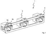
- Fig. 1 shows a schematic view of a camera holder according to an embodiment of the invention.
- FIG. 1 shows a schematic view of a camera holder according to an embodiment of the invention.
- the camera holder 1 comprises in this example three camera housings 2 which are separated and spaced from each other. Further the camera holder 1 comprises a common backside clip 3 which extends over each of the separated camera housings 2.
- the backside clip 3 additionally has spring elements 4a, 4b which are arranged for fixing the position of the respective camera in the respective housing 2. As it can be seen here, the spring elements 4a, 4b match in their position the position of the housings 2.
- the spring elements 4a, 4b are not limited to two elements as shown here. The number spring elements 4a, 4b can be adjusted to provide a sufficient force for fixing the cameras inside the housings 2.
Landscapes
- Engineering & Computer Science (AREA)
- Mechanical Engineering (AREA)
- Multimedia (AREA)
- Signal Processing (AREA)
- Fittings On The Vehicle Exterior For Carrying Loads, And Devices For Holding Or Mounting Articles (AREA)
Abstract
The invention relates to a Camera holder (1) comprising at least two camera housings (2) for receiving an automotive camera in each housing (2) and a backside clip (3), to fix each camera in the respective housing (2), wherein the camera housings (2) and the backside clip (3) are arranged in a common camera bracket. The backside clip (3) is hereby built as one part and is designed to fix each camera in the respective housing (2) simultaneously.
Description
- The invention relates to a camera holder for automotive cameras.
- It is known from the state of the art to have a camera holder which uses connected housings when there is more than one camera.
- It is an object of the invention to provide a camera holder which facilitates mounting multiple cameras in a bracket, and which is more cost efficient.
- First considerations were that the camera position is always different for every vehicle. If the camera position is driven by the backside clip, the housing tool can be reused for several vehicles.
- Also, the camera position needs to follow the low tolerances with the backside clip. The accuracy is driven by the windscreen bracket.
- According to the invention a camera holder is proposed comprising at least two camera housings for receiving an automotive camera in each housing and a backside clip, to fix each camera in the respective housing, wherein the camera housings and the backside clip are arranged in a common camera bracket. According to the invention the backside clip is built as one part and is designed to fix each camera in the respective housing simultaneously.
- The invention is not limited to two camera housings but can be used for three or even more camera housings. The backside clip then needs to be adapted accordingly to match the number of used cameras or camera housings respectively. The backside clip also comprises features, like clips or springs, to fix the backside clip to the camera housings.
- For mounting the camera holder in the bracket, first the camera housings are placed on the bracket. Then the respective cameras are inserted in the respective housings and are then fixed by the backside clip at simultaneously by pushing the common backside clip against the backs of each camera.
- The common camera bracket is a bracket which can be attached e.g., on the inside of a windshield of a vehicle.
- In a preferred embodiment of the invention the at least two camera housings are separated from each other and fixed individually at the camera bracket. Having separated camera housings makes it more feasible to mount the housings on the bracket.
- In a further preferred embodiment, the backside clip is adapted to a distance between and/or a position of the at least two camera housings. This is advantageous since the mounting positions of the housings can be different for several use cases, e.g., different vehicles. It is possible that at least one of the housings has a different vertical position than the at least one other housing. In this case, the backside clip also needs to be adapted to this scenario.
- In a preferred embodiment of the invention the backside clip is made of a plastics material or a metal material or a combination thereof. In a combination the main part could be e.g., made of a plastics material and certain features, like spring elements, could be made of a metal material or vice versa.
- It is further preferred that the backside clip has multiple spring elements which are arranged for fixing the position of the respective camera in the respective housing. The spring elements are arranged to match the openings of the respective housings. Therefore, the spring elements need to be arranged to match the distance between the housings to ensure that the cameras can be fixed in the right position by the common backside clip.
-
Fig. 1 shows a schematic view of a camera holder according to an embodiment of the invention. -
Figure 1 shows a schematic view of a camera holder according to an embodiment of the invention. Thecamera holder 1 comprises in this example threecamera housings 2 which are separated and spaced from each other. Further thecamera holder 1 comprises acommon backside clip 3 which extends over each of theseparated camera housings 2. Thebackside clip 3 additionally hasspring elements respective housing 2. As it can be seen here, thespring elements housings 2. Thespring elements number spring elements housings 2.
Claims (5)
- Camera holder (1) comprising at least two camera housings (2) for receiving an automotive camera in each housing (2) and a backside clip (3), to fix each camera in the respective housing (2), wherein the camera housings (2) and the backside clip (3) are arranged in a common camera bracket,
characterized in that
the backside clip (3) is built as one part and is designed to fix each camera in the respective housing (2) simultaneously. - Camera holder (1) according to claim 1,
characterized in that
the at least two camera housings (2) are separated from each other and fixed individually at the camera bracket. - Camera holder (1) according to claim 1,
characterized in that
the backside clip (3) is adapted to a distance between and/or a position of the at least two camera housings (2). - Camera holder (1) according to claim 1,
characterized in that
the backside clip (3) is made of a plastics material or a metal material or a combination thereof. - Camera holder (1) according to claim 1,
characterized in that
the backside clip (3) has multiple spring elements (4a, 4b) which are arranged for fixing the position of the respective camera in the respective housing (2).
Applications Claiming Priority (2)
| Application Number | Priority Date | Filing Date | Title |
|---|---|---|---|
| IN202341012319 | 2023-02-23 | ||
| DE102023206239.9A DE102023206239B4 (en) | 2023-02-23 | 2023-06-30 | camera mounting device for automotive cameras |
Publications (1)
| Publication Number | Publication Date |
|---|---|
| EP4422190A1 true EP4422190A1 (en) | 2024-08-28 |
Family
ID=89900671
Family Applications (1)
| Application Number | Title | Priority Date | Filing Date |
|---|---|---|---|
| EP24157201.5A Pending EP4422190A1 (en) | 2023-02-23 | 2024-02-12 | Camera holder for automotive cameras |
Country Status (1)
| Country | Link |
|---|---|
| EP (1) | EP4422190A1 (en) |
Citations (4)
| Publication number | Priority date | Publication date | Assignee | Title |
|---|---|---|---|---|
| US20160349600A1 (en) * | 2015-05-26 | 2016-12-01 | Gopro, Inc. | Multi Camera Mount |
| CN113306497A (en) * | 2021-05-27 | 2021-08-27 | 新石器慧通(北京)科技有限公司 | Camera fixed bolster and unmanned car |
| US20210370845A1 (en) * | 2018-10-10 | 2021-12-02 | Bayerische Motoren Werke Aktiengesellschaft | Holding Device for Holding At Least One Driver Assist Sensor Unit, and Arrangement of a Holding Device |
| US20220105879A1 (en) * | 2020-10-02 | 2022-04-07 | Kojima Industries Corporation | In-vehicle camera fixing structure and casing attaching method |
-
2024
- 2024-02-12 EP EP24157201.5A patent/EP4422190A1/en active Pending
Patent Citations (4)
| Publication number | Priority date | Publication date | Assignee | Title |
|---|---|---|---|---|
| US20160349600A1 (en) * | 2015-05-26 | 2016-12-01 | Gopro, Inc. | Multi Camera Mount |
| US20210370845A1 (en) * | 2018-10-10 | 2021-12-02 | Bayerische Motoren Werke Aktiengesellschaft | Holding Device for Holding At Least One Driver Assist Sensor Unit, and Arrangement of a Holding Device |
| US20220105879A1 (en) * | 2020-10-02 | 2022-04-07 | Kojima Industries Corporation | In-vehicle camera fixing structure and casing attaching method |
| CN113306497A (en) * | 2021-05-27 | 2021-08-27 | 新石器慧通(北京)科技有限公司 | Camera fixed bolster and unmanned car |
Similar Documents
| Publication | Publication Date | Title |
|---|---|---|
| US9544487B2 (en) | Camera system with image sensor contacting metallic housing via heat conducting element | |
| US8791611B2 (en) | Device for the contact and attachment of an electric component in a motor vehicle | |
| CN105936242B (en) | The installation constitution of vehicle-mounted sensor | |
| JP2020524777A5 (en) | ||
| US9452714B2 (en) | Fixing system | |
| US10953815B2 (en) | Module and support structure assembly | |
| JP2002225668A (en) | Holding device | |
| EP3173290B1 (en) | Camera bracket with metal wire spring | |
| JP2016016830A (en) | Fitting structure for on-vehicle camera | |
| JP7424582B2 (en) | Bracket for automotive equipment | |
| CN109982895A (en) | Car-mounted electronic device mounting structure | |
| US20200382854A1 (en) | Microphone assembly and microphone arrangement | |
| EP3902706B1 (en) | Driver assist system | |
| JP2018531180A (en) | Indoor mirror base assembly | |
| JP2018531180A6 (en) | Indoor mirror base assembly | |
| EP3461689B1 (en) | Camera device and method for mounting a camera device for a motor vehicle | |
| US20220332381A1 (en) | Method for mounting vehicle elements to a motor vehicle rear end | |
| US20150283950A1 (en) | Device for holding a smartphone inside a vehicle | |
| CN106794806A (en) | Vehicle-mounted pick-up machine support | |
| CN110382300B (en) | Imaging system for a motor vehicle | |
| EP3611565A1 (en) | Image capture device | |
| CN101456432A (en) | Guide structure for installing driver's cab module in vehicle | |
| CN101189146B (en) | Assembly of automobile body element and method of mounting the assembly on an automobile | |
| US9338920B2 (en) | Mounting device for attaching mechanical, electrical and/or electronic modules | |
| CN2916224Y (en) | Spring type car reversing aid system fixing device |
Legal Events
| Date | Code | Title | Description |
|---|---|---|---|
| PUAI | Public reference made under article 153(3) epc to a published international application that has entered the european phase |
Free format text: ORIGINAL CODE: 0009012 |
|
| STAA | Information on the status of an ep patent application or granted ep patent |
Free format text: STATUS: THE APPLICATION HAS BEEN PUBLISHED |
|
| AK | Designated contracting states |
Kind code of ref document: A1 Designated state(s): AL AT BE BG CH CY CZ DE DK EE ES FI FR GB GR HR HU IE IS IT LI LT LU LV MC ME MK MT NL NO PL PT RO RS SE SI SK SM TR |
|
| STAA | Information on the status of an ep patent application or granted ep patent |
Free format text: STATUS: REQUEST FOR EXAMINATION WAS MADE |
|
| 17P | Request for examination filed |
Effective date: 20250228 |
|
| RAP3 | Party data changed (applicant data changed or rights of an application transferred) |
Owner name: AUMOVIO AUTONOMOUS MOBILITY GERMANY GMBH |