EP4422157A1 - Image reading apparatus, information processing system, and program - Google Patents
Image reading apparatus, information processing system, and program Download PDFInfo
- Publication number
- EP4422157A1 EP4422157A1 EP23190178.6A EP23190178A EP4422157A1 EP 4422157 A1 EP4422157 A1 EP 4422157A1 EP 23190178 A EP23190178 A EP 23190178A EP 4422157 A1 EP4422157 A1 EP 4422157A1
- Authority
- EP
- European Patent Office
- Prior art keywords
- image
- paper
- region
- reading
- reading apparatus
- Prior art date
- Legal status (The legal status is an assumption and is not a legal conclusion. Google has not performed a legal analysis and makes no representation as to the accuracy of the status listed.)
- Pending
Links
- 230000010365 information processing Effects 0.000 title claims description 20
- 230000005540 biological transmission Effects 0.000 claims description 69
- 238000003745 diagnosis Methods 0.000 claims description 67
- 239000013256 coordination polymer Substances 0.000 description 40
- 230000007547 defect Effects 0.000 description 28
- 238000010586 diagram Methods 0.000 description 24
- 238000000034 method Methods 0.000 description 20
- 238000012986 modification Methods 0.000 description 19
- 230000004048 modification Effects 0.000 description 19
- 230000008569 process Effects 0.000 description 15
- 230000002950 deficient Effects 0.000 description 14
- 238000012545 processing Methods 0.000 description 10
- 230000006870 function Effects 0.000 description 9
- 239000003086 colorant Substances 0.000 description 5
- 238000004891 communication Methods 0.000 description 5
- 230000005856 abnormality Effects 0.000 description 3
- 230000015572 biosynthetic process Effects 0.000 description 3
- 238000011156 evaluation Methods 0.000 description 3
- 230000015654 memory Effects 0.000 description 3
- 238000004140 cleaning Methods 0.000 description 2
- 230000003287 optical effect Effects 0.000 description 2
- 230000002093 peripheral effect Effects 0.000 description 2
- 230000004044 response Effects 0.000 description 2
- 239000004065 semiconductor Substances 0.000 description 2
- 238000012360 testing method Methods 0.000 description 2
- 230000002159 abnormal effect Effects 0.000 description 1
- 238000001514 detection method Methods 0.000 description 1
- 239000011521 glass Substances 0.000 description 1
- 238000009434 installation Methods 0.000 description 1
- 230000007246 mechanism Effects 0.000 description 1
- 238000002834 transmittance Methods 0.000 description 1
- 230000003936 working memory Effects 0.000 description 1
Images





Classifications
-
- H—ELECTRICITY
- H04—ELECTRIC COMMUNICATION TECHNIQUE
- H04N—PICTORIAL COMMUNICATION, e.g. TELEVISION
- H04N1/00—Scanning, transmission or reproduction of documents or the like, e.g. facsimile transmission; Details thereof
- H04N1/00002—Diagnosis, testing or measuring; Detecting, analysing or monitoring not otherwise provided for
- H04N1/00026—Methods therefor
- H04N1/00045—Methods therefor using a reference pattern designed for the purpose, e.g. a test chart
-
- B—PERFORMING OPERATIONS; TRANSPORTING
- B41—PRINTING; LINING MACHINES; TYPEWRITERS; STAMPS
- B41J—TYPEWRITERS; SELECTIVE PRINTING MECHANISMS, i.e. MECHANISMS PRINTING OTHERWISE THAN FROM A FORME; CORRECTION OF TYPOGRAPHICAL ERRORS
- B41J11/00—Devices or arrangements of selective printing mechanisms, e.g. ink-jet printers or thermal printers, for supporting or handling copy material in sheet or web form
- B41J11/0045—Guides for printing material
-
- H—ELECTRICITY
- H04—ELECTRIC COMMUNICATION TECHNIQUE
- H04N—PICTORIAL COMMUNICATION, e.g. TELEVISION
- H04N1/00—Scanning, transmission or reproduction of documents or the like, e.g. facsimile transmission; Details thereof
- H04N1/00795—Reading arrangements
-
- B—PERFORMING OPERATIONS; TRANSPORTING
- B41—PRINTING; LINING MACHINES; TYPEWRITERS; STAMPS
- B41J—TYPEWRITERS; SELECTIVE PRINTING MECHANISMS, i.e. MECHANISMS PRINTING OTHERWISE THAN FROM A FORME; CORRECTION OF TYPOGRAPHICAL ERRORS
- B41J11/00—Devices or arrangements of selective printing mechanisms, e.g. ink-jet printers or thermal printers, for supporting or handling copy material in sheet or web form
- B41J11/64—Applications of scales or indicators
-
- B—PERFORMING OPERATIONS; TRANSPORTING
- B41—PRINTING; LINING MACHINES; TYPEWRITERS; STAMPS
- B41J—TYPEWRITERS; SELECTIVE PRINTING MECHANISMS, i.e. MECHANISMS PRINTING OTHERWISE THAN FROM A FORME; CORRECTION OF TYPOGRAPHICAL ERRORS
- B41J29/00—Details of, or accessories for, typewriters or selective printing mechanisms not otherwise provided for
- B41J29/38—Drives, motors, controls or automatic cut-off devices for the entire printing mechanism
-
- H—ELECTRICITY
- H04—ELECTRIC COMMUNICATION TECHNIQUE
- H04N—PICTORIAL COMMUNICATION, e.g. TELEVISION
- H04N1/00—Scanning, transmission or reproduction of documents or the like, e.g. facsimile transmission; Details thereof
- H04N1/00002—Diagnosis, testing or measuring; Detecting, analysing or monitoring not otherwise provided for
- H04N1/00005—Diagnosis, testing or measuring; Detecting, analysing or monitoring not otherwise provided for relating to image data
-
- H—ELECTRICITY
- H04—ELECTRIC COMMUNICATION TECHNIQUE
- H04N—PICTORIAL COMMUNICATION, e.g. TELEVISION
- H04N1/00—Scanning, transmission or reproduction of documents or the like, e.g. facsimile transmission; Details thereof
- H04N1/00002—Diagnosis, testing or measuring; Detecting, analysing or monitoring not otherwise provided for
- H04N1/00007—Diagnosis, testing or measuring; Detecting, analysing or monitoring not otherwise provided for relating to particular apparatus or devices
- H04N1/00013—Reading apparatus
-
- H—ELECTRICITY
- H04—ELECTRIC COMMUNICATION TECHNIQUE
- H04N—PICTORIAL COMMUNICATION, e.g. TELEVISION
- H04N1/00—Scanning, transmission or reproduction of documents or the like, e.g. facsimile transmission; Details thereof
- H04N1/00002—Diagnosis, testing or measuring; Detecting, analysing or monitoring not otherwise provided for
- H04N1/00007—Diagnosis, testing or measuring; Detecting, analysing or monitoring not otherwise provided for relating to particular apparatus or devices
- H04N1/00015—Reproducing apparatus
-
- H—ELECTRICITY
- H04—ELECTRIC COMMUNICATION TECHNIQUE
- H04N—PICTORIAL COMMUNICATION, e.g. TELEVISION
- H04N1/00—Scanning, transmission or reproduction of documents or the like, e.g. facsimile transmission; Details thereof
- H04N1/00002—Diagnosis, testing or measuring; Detecting, analysing or monitoring not otherwise provided for
- H04N1/00026—Methods therefor
- H04N1/00029—Diagnosis, i.e. identifying a problem by comparison with a normal state
-
- H—ELECTRICITY
- H04—ELECTRIC COMMUNICATION TECHNIQUE
- H04N—PICTORIAL COMMUNICATION, e.g. TELEVISION
- H04N1/00—Scanning, transmission or reproduction of documents or the like, e.g. facsimile transmission; Details thereof
- H04N1/00795—Reading arrangements
- H04N1/00798—Circuits or arrangements for the control thereof, e.g. using a programmed control device or according to a measured quantity
-
- H—ELECTRICITY
- H04—ELECTRIC COMMUNICATION TECHNIQUE
- H04N—PICTORIAL COMMUNICATION, e.g. TELEVISION
- H04N1/00—Scanning, transmission or reproduction of documents or the like, e.g. facsimile transmission; Details thereof
- H04N1/04—Scanning arrangements, i.e. arrangements for the displacement of active reading or reproducing elements relative to the original or reproducing medium, or vice versa
- H04N1/12—Scanning arrangements, i.e. arrangements for the displacement of active reading or reproducing elements relative to the original or reproducing medium, or vice versa using the sheet-feed movement or the medium-advance or the drum-rotation movement as the slow scanning component, e.g. arrangements for the main-scanning
- H04N1/121—Feeding arrangements
- H04N1/125—Feeding arrangements the sheet feeding apparatus serving an auxiliary function, e.g. as a white reference
-
- H—ELECTRICITY
- H04—ELECTRIC COMMUNICATION TECHNIQUE
- H04N—PICTORIAL COMMUNICATION, e.g. TELEVISION
- H04N1/00—Scanning, transmission or reproduction of documents or the like, e.g. facsimile transmission; Details thereof
- H04N1/00681—Detecting the presence, position or size of a sheet or correcting its position before scanning
- H04N1/00684—Object of the detection
- H04N1/00718—Skew
-
- H—ELECTRICITY
- H04—ELECTRIC COMMUNICATION TECHNIQUE
- H04N—PICTORIAL COMMUNICATION, e.g. TELEVISION
- H04N1/00—Scanning, transmission or reproduction of documents or the like, e.g. facsimile transmission; Details thereof
- H04N1/00681—Detecting the presence, position or size of a sheet or correcting its position before scanning
- H04N1/00729—Detection means
- H04N1/00734—Optical detectors
- H04N1/00737—Optical detectors using the scanning elements as detectors
- H04N1/0074—Optical detectors using the scanning elements as detectors using inactive scanning elements, e.g. elements outside the scanning area
-
- H—ELECTRICITY
- H04—ELECTRIC COMMUNICATION TECHNIQUE
- H04N—PICTORIAL COMMUNICATION, e.g. TELEVISION
- H04N1/00—Scanning, transmission or reproduction of documents or the like, e.g. facsimile transmission; Details thereof
- H04N1/00681—Detecting the presence, position or size of a sheet or correcting its position before scanning
- H04N1/00742—Detection methods
- H04N1/00761—Detection methods using reference marks, e.g. on sheet, sheet holder or guide
-
- H—ELECTRICITY
- H04—ELECTRIC COMMUNICATION TECHNIQUE
- H04N—PICTORIAL COMMUNICATION, e.g. TELEVISION
- H04N1/00—Scanning, transmission or reproduction of documents or the like, e.g. facsimile transmission; Details thereof
- H04N1/04—Scanning arrangements, i.e. arrangements for the displacement of active reading or reproducing elements relative to the original or reproducing medium, or vice versa
- H04N1/12—Scanning arrangements, i.e. arrangements for the displacement of active reading or reproducing elements relative to the original or reproducing medium, or vice versa using the sheet-feed movement or the medium-advance or the drum-rotation movement as the slow scanning component, e.g. arrangements for the main-scanning
- H04N1/121—Feeding arrangements
- H04N1/1215—Feeding using one or more cylindrical platens or rollers in the immediate vicinity of the main scanning line
-
- H—ELECTRICITY
- H04—ELECTRIC COMMUNICATION TECHNIQUE
- H04N—PICTORIAL COMMUNICATION, e.g. TELEVISION
- H04N1/00—Scanning, transmission or reproduction of documents or the like, e.g. facsimile transmission; Details thereof
- H04N1/04—Scanning arrangements, i.e. arrangements for the displacement of active reading or reproducing elements relative to the original or reproducing medium, or vice versa
- H04N1/12—Scanning arrangements, i.e. arrangements for the displacement of active reading or reproducing elements relative to the original or reproducing medium, or vice versa using the sheet-feed movement or the medium-advance or the drum-rotation movement as the slow scanning component, e.g. arrangements for the main-scanning
- H04N1/121—Feeding arrangements
- H04N1/1235—Feeding a sheet past a transparent plate; Details thereof
Definitions
- the present invention relates to an image reading apparatus, an information processing system, and a program.
- JP2020-120246A discloses a configuration as follows.
- An image forming section forms a test pattern on a first recording medium and a second recording medium having a size smaller than the first recording medium while long sides of the first recording medium and the second recording medium coincide with a transport direction.
- An image reading section acquires first diagnosis target data obtained by reading the first recording medium and second diagnosis target data obtained by rotating the second recording medium to have the long side that is in a different direction from the long side of the first recording medium and then reading the second recording medium.
- An abnormal portion is detected and an abnormality factor is diagnosed, by using the test pattern, the first diagnosis target data, the second diagnosis target data, and third diagnosis target data obtained by rotating the second diagnosis target data so that the long side of the second recording medium is in the same direction as the long side of the first recording medium.
- An object of the present invention is to reduce the time and effort for a user to prepare a read image, as compared with a case where a diagnosis as to whether a detected defect is caused by an image forming apparatus or an image reading apparatus is performed by using a plurality of read images.
- an image reading apparatus including a reading unit that reads an image of paper by a relative movement to the paper, an in-paper region that is a region in which the image of the paper is read by the reading unit, and an image that is provided in an out-of-paper region that is a region outside the paper and is used for diagnosing the image of the paper.
- an image reading apparatus according to the first aspect further including a transmission section that transmits a reading result of the reading unit, in which the transmission section may perform switching between a form of transmitting the reading result in the out-of-paper region and a form of transmitting only the reading result in the in-paper region, in transmitting the reading result in the in-paper region.
- an image reading apparatus in which the switching may be performed by an operation of a user.
- an image reading apparatus in which the switching may be performed based on information indicating a diagnostic item using the reading result in the in-paper region.
- an image reading apparatus in which the image in the out-of-paper region may be provided at a position corresponding to any one of four sides of the paper.
- an image reading apparatus according to any one of the second to fifth aspects, in which the image is provided such that the reading result in the out-of-paper region may be an image extending in a direction of a side intersecting a direction of the relative movement.
- an image reading apparatus according to any one of the second to fifth aspects, in which the image in the out-of-paper region may be provided such that the reading result in the out-of-paper region is an image extending in a direction of the relative movement.
- an image reading apparatus in which the image in the out-of-paper region may have a feature for checking a light quantity.
- an image reading apparatus according to the sixth or seventh aspect, in which the image in the out-of-paper region may extend linearly in the direction of the relative movement.
- an image reading apparatus in which the image in the out-of-paper region may be an image arranged at equal intervals in the direction of the relative movement.
- an information processing system including a processor configured to acquire a reading result of an in-paper region that is a region in which an image of paper is read, and a reading result of an out-of-paper region that is a region outside the paper and in which an image used for diagnosing the image of the paper is provided, and perform image quality diagnosis using the acquired reading result of the out-of-paper region, in performing image quality diagnosis on the acquired reading result of the in-paper region.
- a program causing an information processing apparatus to realize a function of acquiring a reading result of an in-paper region that is a region in which an image of paper is read, and a reading result of an out-of-paper region that is a region outside the paper and in which an image used for diagnosing the image of the paper is provided, and a function of performing image quality diagnosis using the acquired reading result of the out-of-paper region, in performing image quality diagnosis on the acquired reading result of the in-paper region.
- the first aspect of the present disclosure it is possible to reduce the time and effort for a user to prepare a read image, as compared with a case where a diagnosis as to whether a detected defect is caused by an image forming apparatus or an image reading apparatus is performed by using a plurality of read images.
- the second aspect of the present disclosure it is possible to reduce a communication load as compared with a case where a transmission section that performs switching between a form of transmitting a reading result in an out-of-paper region and a form of transmitting only a reading result in an in-paper region, in transmitting the reading result in the in-paper region, is not provided.
- the third aspect of the present disclosure it is possible to perform transmission in a transmission form that reflects an intention of a user, as compared with a case where a configuration of switching a transmission form in a case where a reading result in an in-paper region is transmitted, by an operation of the user is not adopted.
- the fourth aspect of the present disclosure it is possible to reduce an operation load of a user as compared with a case where a configuration in which a transmission form in a case where a reading result in an in-paper region is transmitted is performed based on information indicating a diagnostic item using the reading result in the in-paper region is not adopted.
- the fifth aspect of the present disclosure it is possible to reduce the size of an out-of-paper region as compared with a case where a configuration in which an image in the out-of-paper region is provided at a position corresponding to any one of four sides of paper is not adopted.
- the sixth aspect of the present disclosure it is possible to diagnose whether an image extending in the same direction as a direction of a relative movement is caused by an image forming apparatus or the image reading apparatus, as compared with a case where a configuration in which an image is provided such that a reading result in an out-of-paper region is an image extending in a direction of a side intersecting the direction of the relative movement is not adopted.
- the seventh aspect of the present disclosure it is possible to obtain a diagnosis result for a defect caused by inclined paper, with high accuracy, as compared with a case where a configuration in which an image in an out-of-paper region is provided such that a reading result in the out-of-paper region is an image extending in a direction of a relative movement is not adopted.
- the eighth aspect of the present disclosure it is possible to check a light quantity with high accuracy as compared with a case where a configuration in which an image in an out-of-paper region has a feature for checking the light quantity is not adopted.
- the ninth aspect of the present disclosure it is possible to check straightness of movement with high accuracy as compared with a case where a configuration in which an image in an out-of-paper region extends linearly in a direction of a relative movement is not adopted.
- the tenth aspect of the present disclosure it is possible to check fluctuation of a movement speed with high accuracy as compared with a case where a configuration in which an image in an out-of-paper region is an image arranged at equal intervals in a direction of a relative movement is not adopted.
- the eleventh aspect of the present disclosure it is possible to reduce the time and effort for a user to prepare a read image, as compared with a case where a diagnosis as to whether a detected defect is caused by an image forming apparatus or an image reading apparatus is performed by using a plurality of read images.
- the twelfth aspect of the present disclosure it is possible to reduce the time and effort for a user to prepare a read image, as compared with a case where a diagnosis as to whether a detected defect is caused by an image forming apparatus or an image reading apparatus is performed by using a plurality of read images.
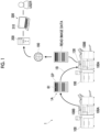
- Fig. 1 is a diagram illustrating an example of a diagnosis system 1.
- the diagnosis system 1 is provided with a plurality of image forming apparatuses 100 and a server apparatus 200 that is connected to each of the plurality of image forming apparatuses 100 via a communication line 190.
- diagnosis of each image forming apparatus 100 is performed in the server apparatus 200 as an example of an information processing system and an example of an information processing apparatus.
- diagnosis system 1 in the present exemplary embodiment is provided with a user terminal 300 that is connected to the server apparatus 200 and receives an operation from a user.
- FIG. 1 two image forming apparatuses 100 among a plurality of image forming apparatuses 100 are displayed.
- the user terminal 300 is provided with a display device 310.
- the user terminal 300 is realized by a computer. Examples of the form of the user terminal 300 include a personal computer (PC), a smartphone, and a tablet terminal.
- PC personal computer
- smartphone smartphone
- tablet terminal a tablet terminal
- the image forming apparatus 100 is provided with an image forming unit 100A as an example of an image forming section that forms an image on paper which is an example of a recording medium.
- the formation of an image on paper by the image forming unit 100A is performed by an inkjet method or an electrophotographic method.
- the formation of an image on paper by the image forming unit 100A is not limited to the inkjet method or the electrophotographic method, but may be performed by other methods.
- the image forming apparatus 100 is further provided with an information processing unit 100B.
- the information processing unit 100B executes various processes executed in the image forming apparatus 100.
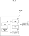
- Fig. 2 is a diagram illustrating an example of a hardware configuration of the information processing unit 100B provided in the server apparatus 200 and the image forming apparatus 100.
- the information processing unit 100B provided in the server apparatus 200 and the image forming apparatus 100 is realized by a computer.
- Each of the server apparatus 200 and the information processing unit 100B includes an arithmetic processing unit 11 that executes a digital arithmetic process according to a program, and a secondary storage unit 12 that stores information.
- the secondary storage unit 12 is realized, for example, by a known information storage device such as a hard disk drive (HDD), a semiconductor memory, or a magnetic tape.
- a hard disk drive HDD
- semiconductor memory a semiconductor memory
- magnetic tape a magnetic tape
- the arithmetic processing unit 11 is provided with a CPU 11a as an example of a processor.
- the arithmetic processing unit 11 is provided with a RAM 11b used as a working memory or the like of the CPU 11a and a ROM 11c in which programs or the like executed by the CPU 11a are stored.
- the arithmetic processing unit 11 is provided with a non-volatile memory 11d that is configured to be rewritable and can hold data even in a case in which power supply is interrupted and an interface unit 11e that controls each unit, such as a communication unit, connected to the arithmetic processing unit 11.
- the non-volatile memory 11d is configured by, for example, an SRAM or a flash memory that is backed up by a battery.
- the secondary storage unit 12 stores the programs executed by the arithmetic processing unit 11 in addition to files and the like.
- the arithmetic processing unit 11 reads the program stored in the ROM 11c or the secondary storage unit 12 to perform each process.
- the program executed by the CPU 11a can be provided to the server apparatus 200 and the information processing unit 100B in a state in which the program is stored in a computer-readable recording medium such as a magnetic recording medium (for example, a magnetic tape or a magnetic disk), an optical recording medium (for example, an optical disk), a magnetooptical recording medium, or a semiconductor memory. Further, the program executed by the CPU 11a may be provided to the server apparatus 200 and the information processing unit 100B by a communication unit such as the Internet.
- a computer-readable recording medium such as a magnetic recording medium (for example, a magnetic tape or a magnetic disk), an optical recording medium (for example, an optical disk), a magnetooptical recording medium, or a semiconductor memory.
- the program executed by the CPU 11a may be provided to the server apparatus 200 and the information processing unit 100B by a communication unit such as the Internet.
- processor refers to hardware in a broad sense.
- Examples of the processor include general processors (e.g., CPU: Central Processing Unit) and dedicated processors (e.g., GPU: Graphics Processing Unit, ASIC: Application Specific Integrated Circuit, FPGA: Field Programmable Gate Array, and programmable logic device).
- processor is broad enough to encompass one processor or plural processors in collaboration which are located physically apart from each other but may work cooperatively.
- the order of operations of the processor is not limited to one described in the embodiments above, and may be changed.
- the process executed by the image forming apparatus 100 among the processes described below is executed by the CPU 11a as an example of the processor provided in the image forming apparatus 100.
- the process executed by the server apparatus 200 among the processes described below is executed by the CPU 11a as an example of the processor provided in the server apparatus 200.
- the process for diagnosing the image forming apparatus 100 among the processes described below is executed by the server apparatus 200 as an example of the information processing system.
- the information processing system that executes the process for diagnosing the image forming apparatus 100 may be realized by one apparatus such as one server apparatus 200, or may be realized by a plurality of apparatus.
- Fig. 3 is a diagram illustrating the image forming apparatus 100.
- the image forming apparatus 100 is provided with the image forming unit 100A that forms an image on paper P which is an example of a recording medium.
- the paper P passes through the image forming unit 100A in a state where one side of the paper P faces the image forming unit 100A.
- the image forming apparatus 100 is provided with an image reading apparatus 130 as an example of an image reading section that reads the image formed on the recording medium such as the paper P.
- Such an image reading apparatus 130 is a so-called scanner having a function of transporting the paper P.
- the image reading apparatus 130 includes a light source that emits light to paper P and a light receiving unit such as a CCD, that receives reflected light from the paper P.
- read image data described later is generated based on the reflected light received by the light receiving unit.
- a reading position of an image is set in advance in the image reading apparatus 130, and the image reading apparatus 130 reads an image at a portion of paper P that is sequentially transported, which is located at the reading position.
- the image forming apparatus 100 has an information transmission function of transmitting information to the server apparatus 200 (see Fig. 1 ).
- the image reading apparatus 130 is provided above the image forming apparatus 100.
- the image reading apparatus 130 sequentially reads paper (not illustrated) set by the user.
- the paper is not limited to paper on which an image is formed by the image forming apparatus 100, and may be paper on which an image is formed by another image forming apparatus.
- An installation form of the image reading apparatus 130 is not limited to the form illustrated in Fig. 3 .
- the image reading apparatus 130 may be provided inside the image forming apparatus 100 and on a transport path of paper P.
- the paper P on which an image is formed by the image forming unit 100A sequentially passes through the image reading apparatus 130, and at the time of passing through the paper P, each image of the paper P is read in order.
- the image reading apparatus 130 is provided with a paper reversing mechanism so that the paper can be supplied after the front and back sides have been reversed with respect to the reading position of the image.
- the paper on which an image formed on one side is read can be reversed and supplied to the reading position again.
- images on the front and back sides of the paper can be read.
- the paper is placed on a platen (not illustrated) configured by plate-shaped glass or the like so that the paper placed on the platen may be read.
- each image forming apparatus 100 is provided with an operation reception unit that receives an operation from the user.
- the operation reception unit is configured by a so-called touch panel.
- the operation reception unit displays information for the user and receives an operation performed by the user.
- the display of information for the user and the reception of the operation by the user are not limited to being performed by one operation reception unit as in the present exemplary embodiment.
- the operation reception unit and the information display unit may be provided separately.
- the image forming unit 100A is operated to form a chart image 61 (see Fig. 1 ) on paper.
- chart paper CP which is the paper on which a chart image 61 that is an example of a diagnosis image has been formed is generated.
- a chart image 61 is an image used to diagnose the image forming apparatus 100.
- the chart paper CP which is the paper on which the chart image 61 used for the diagnosis has been formed is generated.
- the chart paper CP is installed on the image reading apparatus 130 as indicated by the reference sign 1B in Fig. 1 .
- the image reading apparatus 130 is used to read the chart paper CP on which the chart image 61 is formed.
- the read image data is transmitted to the server apparatus 200 and then is stored in the server apparatus 200.
- the server apparatus 200 diagnoses the image forming apparatus 100 based on the read image data.
- a user who uses the diagnosis system 1 in the present exemplary embodiment such as a maintainer who maintains the image forming apparatus 100, accesses the server apparatus 200 and refers to the result of the diagnosis by the server apparatus 200.
- each image forming apparatus 100 as described above, the chart paper CP is generated and the chart paper CP is read, and thus the read image data is generated.
- Such read image data is transmitted to the server apparatus 200.
- the server apparatus 200 diagnoses the image forming apparatus 100.
- a diagnosis process executed by the server apparatus 200 will be described.
- the CPU 11a (see Fig. 2 ) as an example of the processor provided in the server apparatus 200 diagnoses the image forming apparatus 100 based on the above-described read image data transmitted from the image forming apparatus 100, and then acquires the diagnosis result which is the result of the diagnosis.
- the CPU 11a acquires a diagnosis result for each of a plurality of diagnostic items, which is a diagnosis result for the chart image 61 that is the image formed on the chart paper CP.
- a plurality of diagnostic items are predetermined.
- the CPU 11a in the server apparatus 200 analyzes the chart image 61 included in the read image data, and acquires a diagnosis result for each of the plurality of diagnostic items.
- the CPU 11a in the server apparatus 200 acquires the diagnosis result for each of the diagnostic items based on a difference between the reference value predetermined for each of the plurality of diagnostic items and the value obtained by analyzing the chart image 61.
- the CPU 11a in the server apparatus 200 acquires a diagnosis result having a worse evaluation as the difference increases.
- the CPU 11a rearranges a plurality of acquired diagnosis results so that the plurality of acquired diagnosis results are arranged in a predetermined order.
- the CPU 11a rearranges a plurality of the diagnosis results so that, for example, a plurality of the diagnosis results are arranged in an order of a bad evaluation or a good evaluation.
- the CPU 11a generates a screen in which the plurality of diagnosis results are arranged in a predetermined order.
- the server apparatus 200 acquires the read image data from the image forming apparatus 100, and the server apparatus 200 executes the diagnosis process.
- the present disclosure is not limited to this, and the image forming apparatus 100 itself may execute the diagnosis process without transmission of the read image data.
- Fig. 4 is a block diagram illustrating a functional configuration of the CPU 11a in the image forming apparatus 100.
- the CPU 11a includes a transmission form setting unit 13 and an image information acquisition unit 14.
- the transmission form setting unit 13 sets a form in which the reading result of the image reading apparatus 130 is transmitted to the server apparatus 200 that executes the diagnosis process.
- the image information acquisition unit 14 acquires image information as the reading result of the image reading apparatus 130.
- the image information acquisition unit 14 sets the acquired image information into a transmission form set by the transmission form setting unit 13.
- the image information in such a transmission form is transmitted to the server apparatus 200 (see Fig. 1 ) via the interface unit 11e.
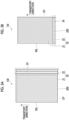
- Figs. 5A and 5B are diagrams illustrating a reading region 20 provided in the image reading apparatus 130, in which Fig. 5A illustrates a first configuration example and Fig. 5B illustrates a second configuration example.
- the reading region 20 illustrated in Figs. 5A and 5B includes an in-paper region 21 that is a region in which the chart image 61 (see Fig. 1 ) of chart paper CP is read, and an out-of-paper region 22 that is a region outside the in-paper region 21.
- the outer shape of the chart paper CP is indicated by the broken line in the in-paper region 21.
- the in-paper region 21 of the reading region 20 has a size required to read the chart image 61 (see Fig. 1 ) of the chart paper CP.
- the size of the in-paper region 21 may be larger than the chart image 61, for example, substantially equal to the dimensions of the outer shape of the chart paper CP.
- a margin may be provided around the outer shape of the chart paper CP to be larger than the outer shape of the chart paper CP.
- the out-of-paper region 22 of the reading region 20 is a region outside the chart paper CP and is provided adjacent to the in-paper region 21.
- the out-of-paper region 22 is provided on any one of four sides of the in-paper region 21. That is, in the first configuration example of Fig. 5A , the out-of-paper region 22 is provided on a side of the reading region 20, that extends in a transport direction. In the second configuration example of Fig. 5B , the out-of-paper region 22 is provided on a side thereof extending in a direction intersecting the transport direction. As described above, the relative positional relationship between the in-paper region 21 and the out-of-paper region 22 is different between the first configuration example and the second configuration example.
- the reading region 20 may be configured to include both the out-of-paper region 22 in the first configuration example and the out-of-paper region 22 in the second configuration example.
- the long side of the four sides of a rectangle is referred to as a long side 20L
- the short side is referred to as a short side 20S.
- the long side 20L and the short side 20S of the reading region 20 can be referred to as the long side and the short side of the in-paper region 21, and can be referred to as the long side and the short side of the out-of-paper region 22.
- the long side 20L and the short side 20S can be referred to as the long side and the short side of the chart paper CP in a case where the chart paper CP is located in the in-paper region 21.
- the reading region 20 of the image reading apparatus 130 will be described more specifically.
- the out-of-paper region 22 in the first configuration example is provided at a position corresponding to a long side 20L.
- a linear image 23 extending in a direction of the long side 20L is provided in the out-of-paper region 22.
- the image 23 extends in the transport direction of the chart paper CP. As described above, the image 23 is provided in the out-of-paper region 22 in the first configuration example such that a read image example 30 (see, for example, Fig. 6A ) is a straight image 33 extending in the direction of the long side of the chart paper CP.
- the out-of-paper region 22 in the second configuration example is provided at a position corresponding to a short side 20S, differing from the first configuration example.
- a linear image 24 extending in the same direction as a direction in which the short side 20S extends is provided in the out-of-paper region 22.
- the image 24 extends in a direction intersecting the transport direction of the chart paper CP, and is provided such that the read image example 30 (see, for example, Fig. 6B ) is a straight image 34 extending in the direction of the short side of the chart paper CP.
- the image 23 in the first configuration example and the image 24 in the second configuration example are examples of an image used for diagnosis.
- the colors or patterns of the image 23 in the first configuration example are different from the colors or patterns of the image 24 in the second configuration example.
- the image 23 may be set to be white and the image 24 may be set to be black. This is because the images 23 and 24 perform different functions in diagnosis, and may perform the same function. Details of each function of the images 23 and 24 will be described later.
- the read image example 30 that is an image example of the chart paper CP placed in the reading region 20 of the image reading apparatus 130 will be described with reference to Fig. 6 .
- Figs. 6A to 6C are diagrams illustrating an example of the read image example 30 obtained by reading the chart paper CP placed in the reading region 20, in which Fig. 6A illustrates a read image example 30 in the first configuration example, and Figs. 6B and 6C illustrate a read image example 30 in the second configuration example.
- Each of the read image examples 30 illustrated in Figs. 6A to 6C includes a paper image 31 corresponding to the chart paper CP (refer to the broken line portion in Fig. 5A or 5B ) of the in-paper region 21.
- the read image example 30 illustrated in Fig. 6A includes not only the paper image 31, but also a straight image 33 corresponding to the linear image 23 (see Fig. 5A ) in the out-of-paper region 22.
- the read image example 30 illustrated in Figs. 6B and 6C includes not only the paper image 31, but also a straight image 34 corresponding to the linear image 24 (see Fig. 5B ) in the out-of-paper region 22.
- the paper image 31 corresponding to the chart paper CP is inclined with respect to the straight image 33. That is, the long side of the paper image 31 is not parallel to a direction in which the straight image 33 extends. Therefore, according to the read image example 30, it is possible to detect that the chart paper CP is read in the inclined state in the in-paper region 21 (see Fig. 5A ), and to grasp that a defect due to the diagnosis is caused by the image reading apparatus.
- the image 23 (see Fig. 5A ) corresponding to the straight image 33 can be referred to as a diagnostic feature for diagnosing a paper state of the image reading apparatus.
- the server apparatus 200 diagnoses the paper state.
- a defective image 35 extending in a streak shape appears.
- the defective image 35 appears in the paper image 31 corresponding to the chart paper CP
- the defective image 35 does not appear in the straight image 34 corresponding to the linear image 24 (see Figs. 5A and 5B ). That is, the defective image 35 is obtained by reading the defective image formed on the chart image 61 (see Fig. 1 ) of the chart paper CP. Therefore, according to the read image example 30, it is possible to detect that the defective image 35 is not caused by the image reading apparatus 130 but is caused by the image forming unit 100A (see Fig. 3 ) that forms the chart image 61.
- the image 24 (see Fig. 5B ) corresponding to the straight image 34 can refer to a streak detection feature for diagnosing the cause of the detected streak-shaped image.
- a defective image 36 extending in a streak shape appears.
- the defective image 36 appears in both the paper image 31 and the straight image 34, differing from the defective image 35 described above. That is, the defective image 36 is not based on the defective image shown in the chart image 61 (see Fig. 1 ), and is formed by the image reading apparatus 130. Therefore, according to the read image example 30, it is possible to detect that the defective image 36 is not caused by the image forming unit 100A (see Fig. 3 ) that forms the chart image 61, but is caused by the image reading apparatus 130.
- the image 24 (see Fig. 5B ) may be set to have a dark color, for example, a black color.
- the server apparatus 200 according to the read image example 30 in any one of Figs. 6A to 6C , it is possible to diagnose that there is a defect in the chart image 61 which is a diagnosis target, and diagnose whether the defect is caused by the image forming unit 100A or the image reading apparatus 130. That is, in the case of the read image example 30 in Fig. 6A , the defect is caused by the image reading apparatus 130. Further, in the case of the read image example 30 of Fig. 6B , the defect is caused by the image forming unit 100A. In the case of the read image example 30 of Fig. 6C , the defect is caused by the image reading apparatus 130.
- Figs. 7A to 7C are diagrams illustrating transmission images 41, 42, and 43 transmitted to the server apparatus 200, in which Fig. 7A illustrates the transmission image 41, Fig. 7B illustrates another transmission image 42, and Fig. 7C illustrates the other transmission image 43.
- the transmission images 41 to 43 are created by the image information acquisition unit 14 of the CPU 11a described above, and are transmitted to the server apparatus 200 by the interface unit 11e (see Fig. 2 ).
- the transmission images 41 to 43 are examples of the reading result of the image reading apparatus 130 (see Fig. 3 ).
- the interface unit 11e is an example of a transmission section that transmits the reading results together with the CPU 11a.
- the transmission image 41 illustrated in Fig. 7A includes not only the paper image 31 but also the straight image 33.
- the transmission image 42 illustrated in Fig. 7B includes the paper image 31 and the straight image 34.
- the transmission image 43 illustrated in Fig. 7C includes the paper image 31, the transmission image 43 includes neither the straight image 33 nor 34.
- the transmission images 41 and 42 include the paper image 31, and the straight image 33 or the straight image 34, and the transmission image 43 includes only the paper image 31.
- the transmission image 41 is an image in a case where the image reading apparatus 130 (see Fig. 3 ) is the first configuration example (see Fig. 5A ).
- the transmission image 42 is an image in a case where the image reading apparatus 130 is the second configuration example (see Fig. 5B ).
- the transmission image 43 can be set to have the transmission content regardless of whether the image reading apparatus 130 is the first configuration example or the second configuration example.
- the image reading apparatus 130 in a case where the image reading apparatus 130 (see Fig. 3 ) is the first configuration example (see Fig. 5A ), either the transmission image 41 or the transmission image 43 is used. In the case of the second configuration example (see Fig. 5B ), either the transmission image 42 or the transmission image 43 is used.
- the CPU 11a acquires such information by reading the information from the ROM 11c.
- the transmission form setting unit 13 determines whether to transmit the transmission image 41 or the transmission image 43.
- the transmission form setting unit 13 determines whether to transmit the transmission image 42 or the transmission image 43.
- the transmission form setting unit 13 switches a form of transmitting the reading result to the server apparatus 200, between a form of transmitting the transmission images 41 and 42 including the paper image 31 as the reading result of the in-paper region 21 and the straight images 33 and 34 as the reading result of the out-of-paper region 22, and a form of transmitting the transmission image 43 including only the paper image 31. Such switching is performed in order to determine whether or not the transmission form including the straight images 33 and 34 as the reading result of the out-of-paper region 22 is set.
- the above-described image information acquisition unit 14 acquires the information of the read image in a form predetermined by the transmission form setting unit 13.
- the acquired information of the image is transmitted to the server apparatus 200 (see Fig. 1 ) by the interface unit 11e (see Fig. 2 ) and is used for diagnosis.
- the transmission form setting unit 13 may use, as information for determining the transmission form, information indicating an operation result of the user, or may use information indicating a diagnostic item in the diagnosis process executed by the server apparatus 200.
- the user instructs the transmission images 41 and 42 to be transmitted by an operation by an operation unit (not illustrated). Further, in a case where it is considered that such a necessity is not necessary, the user instructs the transmission image 43 to be transmitted by an operation of the operation unit (not illustrated).
- the transmission form setting unit 13 switches the transmission form in response to the operation instruction. This is a manual switching of transmission forms.
- the transmission form setting unit 13 acquires information indicating a diagnostic item using the reading result in the in-paper region 21 by the server apparatus 200, and automatically switches the transmission form in accordance with the acquired information. For example, in a case where the diagnostic items are only items that are not related to the inclination of the image or the presence or absence of the defective image, the transmission image 43 (see Fig. 7C ) is transmitted, so that the amount of data to be transmitted is reduced, and it is possible to reduce the processing load of the server apparatus 200.
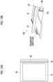
- Figs. 8A to 8C are diagrams illustrating a first modification example, in which Fig. 8A illustrates a read image example 30, and Figs. 8B and 8C illustrate a configuration of an image reading apparatus 130.
- the straight image 33 of the read image example 30 includes a feature image 51 for determining a light quantity of the image reading apparatus 130.
- the feature image 51 includes a feature portion 52 for detecting the light quantity and white balance, and a feature portion 53 for detecting a reference color.
- the feature portion 52 is a straight line on the right side of three vertical columns, and the feature portion 53 is a straight line on the center side and a straight line on the left side.
- a white image is formed in the feature portion 52, and an image having a reference color to be detected is formed in the feature portion 53.
- the number of straight lines to be provided varies depending on the number of the reference colors.
- the server apparatus 200 By transmitting the read image example 30 including the feature image 51 to the server apparatus 200, it is possible to correct the density in the in-paper region 21 and then perform diagnosis. In a case where the density abnormality is detected, it is possible to determine whether the density abnormality is caused by image formation or image reading.
- the configuration of the image reading apparatus 130 may be illustrated in Fig. 8B or Fig. 8C .
- the chart paper CP is transported to a reading position by a plurality of transporting members.
- each case will be described.
- the image reading apparatus 130 includes a reading unit 131 and a transport roller 132.
- the reading unit 131 includes a light source that emits light emitted toward the chart image 61 of the chart paper CP and a light receiving unit that receives the reflected light.
- the transport roller 132 is provided at a position facing the reading unit 131 as one of the plurality of transporting members. Thus, the chart image 61 of the chart paper CP is read by the relative movement to the chart paper CP.
- An image 133 is provided in a region of the transport roller 132 corresponding to the out-of-paper region 22.
- An image 133 corresponds to the image 23 (see Fig. 5A ) in the present exemplary embodiment described above, and is an image for forming the above-described feature image 51 in image reading. That is, the image 133 is provided to extend over the entire circumference in the circumferential direction of the transport roller 132. In a case where the image 133 is read in a case where the transport roller 132 is rotating, the read image is the straight image 33 (see Fig. 8A ) including the linear feature image 51.
- the image 133 of the transport roller 132 is an example of an image having a feature for checking the light quantity.
- the image reading apparatus 130 illustrated in Fig. 8C includes a reference plate 134 located behind the transport roller 132 in the transport direction in addition to the reading unit 131 described above and the transport roller 132 described above.
- the image 133 is provided in a flat region of the reference plate 134 corresponding to the out-of-paper region 22.
- the image 133 of the reference plate 134 is the same as the image 133 illustrated in Fig. 8B described above. That is, the image 133 is provided on the transport roller 132 in Fig. 8B and is provided on the reference plate 134 in Fig. 8C .
- Figs. 9A to 9C are diagrams illustrating a second modification example, in which Fig. 9A illustrates a read image example 30, and Figs. 9B and 9C illustrate a configuration of an image reading apparatus 130 (see Fig. 3 ).
- the straight image 33 of the read image example 30 includes a feature image 54 for determining the straightness in paper transport of the image reading apparatus 130.
- the feature image 54 is an image extending in the transport direction, and is not linear but meandering in a direction intersecting the transport direction for a reason described later. Such a transport direction is the direction of the relative movement to the chart paper CP in image reading.
- the paper image 31 of the read image example 30 includes each color alignment image which is a chart image 61, and further includes a boundary portion 32 indicating a paper edge of the chart paper CP.
- Each color alignment image referred to here is an image for checking whether or not a positional deviation between the respective colors has occurred, and is an image in which the colors are arranged in order in a long side direction and the deviation in a short side direction is facilitated to be visually recognized.
- FIG. 9B the configuration of the image reading apparatus 130 may be illustrated in Fig. 9B or Fig. 9C .
- An image 135 for forming the straight image 33 of the read image example 30 is formed on the peripheral surface of the transport roller 132 in Fig. 9B , and is formed on the flat surface of the reference plate 134 in Fig. 9C .
- Such an image 135 has a feature for checking the straightness.
- the image 135 is an image having a feature for checking the straightness, and is an example of an image extending linearly in the direction of the relative movement.
- a paper edge CP1 of the chart paper CP is also used in order to check the straightness of the paper transport.
- FIGs. 9B and 9C portions common to those in Figs. 8B and 8C illustrating the case of the first modification example described above are denoted by the same reference signs, and descriptions of the common portions will not be repeated.
- the image 135 corresponds to the image 133 in the first modification example.
- the straight image 33 that is originally a linear image is not a straight line, and the boundary portion 32 indicating the paper edge CP1 of the chart paper CP is also meandering.
- the transport roller 132 meanders (see Fig. 9B ) or the reading unit 131 meanders (see Fig. 9C ) during image reading there is a probability that the transport roller 132 shifts to the right or left as in the read image example 30.
- Figs. 10A and 10B are diagrams illustrating a third modification example, in which Fig. 10A illustrates a read image example 30, and Fig. 10B illustrates a configuration of an image reading apparatus 130 (see Fig. 3 ).
- the straight image 33 of the read image example 30 includes a feature image 55 for determining a fluctuation in the transport speed of the image reading apparatus 130.
- the feature image 55 is a line extending in a width direction and a line arranged at intervals in a length direction.
- an image 136 for forming a straight image 33 is formed on the transport roller 132.
- the image 136 has a feature for checking a fluctuation in the transport speed. More specifically, in the image 136, lines are provided at predetermined intervals in the circumferential direction of the transport roller 132. Such an interval is obtained by equally dividing the peripheral length, is equal over the entire circumference, and is an equal interval.
- the feature images 55 of the read image example 30 are at equal intervals.
- a portion that does not have an equal interval appears in the feature image 55.
- FIG. 10B portions common to those in Figs. 8B and 8C illustrating the case of the first modification example described above are denoted by the same reference signs, and descriptions of the common portions will not be repeated.
- the image 136 corresponds to the image 133 in the first modification example.
- the image 136 is an example of an image arranged at equal intervals in the direction of the relative movement in image reading.
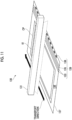
- Fig. 11 is a diagram illustrating an image reading apparatus 130 according to a fourth modification example. Fig. 11 illustrates that a portion of the image forming apparatus 100 turns upside down.
- the image reading apparatus 130 includes a platen 137, a reading unit 131, and a document cover (not illustrated).
- the platen 137 has light transmittance and has an upper surface on which the chart paper CP is placed.
- the reading unit 131 is located on a lower surface 138 side of the platen 137 and moves with respect to the platen 137.
- the document cover covers the upper surface of the platen 137, and opens and closes the main body of the image reading apparatus 130.
- an image 139 is provided in the region of the platent 137.
- the image 139 is located at a position corresponding to the out-of-paper region 22 (see Figs. 5A and 5B ).
- the image 139 includes the above-described image 133 (see Fig. 8B or 8C ) for checking the color, the light quantity, and the white balance, the above-described image 135 (see Fig. 9B or 9C ) for checking the straightness in image reading, and the above-described image 136 (see Fig. 10B ) for checking the speed fluctuation in the image reading described above.
- Figs. 12A and 12B are diagrams illustrating a display example of an image quality diagnosis result of the display device 310, in which Fig. 12A illustrates an example and Fig. 12B illustrates another example. More specifically, Fig. 12A illustrates an example in a case where the defect is caused by the image reading apparatus, and Fig. 12B illustrates another example in a case where the defect is caused by the image forming apparatus.
- the display device 310 illustrated in Fig. 12A shows that there is a defect in image quality, an image quality level is "NG", and the detected defect is "density unevenness”.
- the failure location is "transport of the image reading apparatus”. That is, it is shown that the cause of the density unevenness is in the image reading apparatus and not in the image forming apparatus.
- Such cause specifying can be performed using the above-described read image example 30 (see, for example, Figs. 9A to 9C ).
- the treatment content is for the image reading apparatus, and indicates "cleaning of the transport roller in the image reading apparatus” and "replacement of the transport roller of the image reading apparatus". For example, there are cleaning of the transport roller 132 (see Figs. 9A to 9C ) or replacement of components.
- the display device 310 illustrated in Fig. 12B shows that there is a defect in image quality, the image quality level is "NG”, the detected defect is “density unevenness”, and the failure location is "drum”, that is, the cause of the defect occurring is in the image forming apparatus and not in the image reading apparatus.
- the treatment contents are "density adjustment” and "drum replacement”.
Landscapes
- Engineering & Computer Science (AREA)
- Multimedia (AREA)
- Signal Processing (AREA)
- Health & Medical Sciences (AREA)
- Biomedical Technology (AREA)
- General Health & Medical Sciences (AREA)
- Facsimiles In General (AREA)
- Facsimile Scanning Arrangements (AREA)
- Control Or Security For Electrophotography (AREA)
Abstract
An image reading apparatus includes a reading unit that reads an image of paper by a relative movement to the paper, an in-paper region that is a region in which the image of the paper is read by the reading unit, and an image that is provided in an out-of-paper region that is a region outside the paper and is used for diagnosing the image of the paper.
Description
- The present invention relates to an image reading apparatus, an information processing system, and a program.
- For example,
JP2020-120246A - Here, in a case where an image that is formed on paper by an image forming apparatus and read by an image reading apparatus is diagnosed, in an attempt to distinguish whether a defect due to the diagnosis is caused by the image forming apparatus or the image reading apparatus, for example, a plurality of read images with different reading directions are required, and thus it takes time and effort for a user to prepare the read images.
- An object of the present invention is to reduce the time and effort for a user to prepare a read image, as compared with a case where a diagnosis as to whether a detected defect is caused by an image forming apparatus or an image reading apparatus is performed by using a plurality of read images.
- According to a first aspect of the present disclosure, there is provided an image reading apparatus including a reading unit that reads an image of paper by a relative movement to the paper, an in-paper region that is a region in which the image of the paper is read by the reading unit, and an image that is provided in an out-of-paper region that is a region outside the paper and is used for diagnosing the image of the paper.
- According to a second aspect of the present disclosure, there is provided an image reading apparatus according to the first aspect further including a transmission section that transmits a reading result of the reading unit, in which the transmission section may perform switching between a form of transmitting the reading result in the out-of-paper region and a form of transmitting only the reading result in the in-paper region, in transmitting the reading result in the in-paper region.
- According to a third aspect of the present disclosure, there is provided an image reading apparatus according to the second aspect, in which the switching may be performed by an operation of a user.
- According to a fourth aspect of the present disclosure, there is provided an image reading apparatus according to the second aspect, in which the switching may be performed based on information indicating a diagnostic item using the reading result in the in-paper region.
- According to a fifth aspect of the present disclosure, there is provided an image reading apparatus according to the first aspect, in which the image in the out-of-paper region may be provided at a position corresponding to any one of four sides of the paper.
- According to a sixth aspect of the present disclosure, there is provided an image reading apparatus according to any one of the second to fifth aspects, in which the image is provided such that the reading result in the out-of-paper region may be an image extending in a direction of a side intersecting a direction of the relative movement.
- According to a seventh aspect of the present disclosure, there is provided an image reading apparatus according to any one of the second to fifth aspects, in which the image in the out-of-paper region may be provided such that the reading result in the out-of-paper region is an image extending in a direction of the relative movement.
- According to an eighth aspect of the present disclosure, there is provided an image reading apparatus according to the sixth or seventh aspect, in which the image in the out-of-paper region may have a feature for checking a light quantity.
- According to a ninth aspect of the present disclosure, there is provided an image reading apparatus according to the sixth or seventh aspect, in which the image in the out-of-paper region may extend linearly in the direction of the relative movement.
- According to a tenth aspect of the present disclosure, there is provided an image reading apparatus according to the sixth or seventh aspect, in which the image in the out-of-paper region may be an image arranged at equal intervals in the direction of the relative movement.
- According to an eleventh aspect of the present disclosure, there is provided an information processing system including a processor configured to acquire a reading result of an in-paper region that is a region in which an image of paper is read, and a reading result of an out-of-paper region that is a region outside the paper and in which an image used for diagnosing the image of the paper is provided, and perform image quality diagnosis using the acquired reading result of the out-of-paper region, in performing image quality diagnosis on the acquired reading result of the in-paper region.
- According to a twelfth aspect of the present disclosure, there is provided a program causing an information processing apparatus to realize a function of acquiring a reading result of an in-paper region that is a region in which an image of paper is read, and a reading result of an out-of-paper region that is a region outside the paper and in which an image used for diagnosing the image of the paper is provided, and a function of performing image quality diagnosis using the acquired reading result of the out-of-paper region, in performing image quality diagnosis on the acquired reading result of the in-paper region.
- According to the first aspect of the present disclosure, it is possible to reduce the time and effort for a user to prepare a read image, as compared with a case where a diagnosis as to whether a detected defect is caused by an image forming apparatus or an image reading apparatus is performed by using a plurality of read images.
- According to the second aspect of the present disclosure, it is possible to reduce a communication load as compared with a case where a transmission section that performs switching between a form of transmitting a reading result in an out-of-paper region and a form of transmitting only a reading result in an in-paper region, in transmitting the reading result in the in-paper region, is not provided.
- According to the third aspect of the present disclosure, it is possible to perform transmission in a transmission form that reflects an intention of a user, as compared with a case where a configuration of switching a transmission form in a case where a reading result in an in-paper region is transmitted, by an operation of the user is not adopted.
- According to the fourth aspect of the present disclosure, it is possible to reduce an operation load of a user as compared with a case where a configuration in which a transmission form in a case where a reading result in an in-paper region is transmitted is performed based on information indicating a diagnostic item using the reading result in the in-paper region is not adopted.
- According to the fifth aspect of the present disclosure, it is possible to reduce the size of an out-of-paper region as compared with a case where a configuration in which an image in the out-of-paper region is provided at a position corresponding to any one of four sides of paper is not adopted.
- According to the sixth aspect of the present disclosure, it is possible to diagnose whether an image extending in the same direction as a direction of a relative movement is caused by an image forming apparatus or the image reading apparatus, as compared with a case where a configuration in which an image is provided such that a reading result in an out-of-paper region is an image extending in a direction of a side intersecting the direction of the relative movement is not adopted.
- According to the seventh aspect of the present disclosure, it is possible to obtain a diagnosis result for a defect caused by inclined paper, with high accuracy, as compared with a case where a configuration in which an image in an out-of-paper region is provided such that a reading result in the out-of-paper region is an image extending in a direction of a relative movement is not adopted.
- According to the eighth aspect of the present disclosure, it is possible to check a light quantity with high accuracy as compared with a case where a configuration in which an image in an out-of-paper region has a feature for checking the light quantity is not adopted.
- According to the ninth aspect of the present disclosure, it is possible to check straightness of movement with high accuracy as compared with a case where a configuration in which an image in an out-of-paper region extends linearly in a direction of a relative movement is not adopted.
- According to the tenth aspect of the present disclosure, it is possible to check fluctuation of a movement speed with high accuracy as compared with a case where a configuration in which an image in an out-of-paper region is an image arranged at equal intervals in a direction of a relative movement is not adopted.
- According to the eleventh aspect of the present disclosure, it is possible to reduce the time and effort for a user to prepare a read image, as compared with a case where a diagnosis as to whether a detected defect is caused by an image forming apparatus or an image reading apparatus is performed by using a plurality of read images.
- According to the twelfth aspect of the present disclosure, it is possible to reduce the time and effort for a user to prepare a read image, as compared with a case where a diagnosis as to whether a detected defect is caused by an image forming apparatus or an image reading apparatus is performed by using a plurality of read images.
- Exemplary embodiment(s) of the present invention will be described in detail based on the following figures, wherein:
-
Fig. 1 is a diagram illustrating an example of a diagnosis system; -
Fig. 2 is a diagram illustrating an example of a hardware configuration of an information processing unit provided in a server apparatus and an image forming apparatus; -
Fig. 3 is a diagram illustrating the image forming apparatus; -
Fig. 4 is a block diagram illustrating a functional configuration of a CPU in the image forming apparatus; -
Figs. 5A and 5B are diagrams illustrating a reading region provided in an image reading apparatus, in whichFig. 5A illustrates a first configuration example andFig. 5B illustrates a second configuration example; -
Figs. 6A to 6C are diagrams illustrating an example of a read image obtained by reading chart paper placed in the reading region, in whichFig. 6A illustrates a read image example in a first configuration example, andFigs. 6B and6C illustrate a read image example in a second configuration example; -
Figs. 7A to 7C are diagrams illustrating a transmission image by an interface unit, in whichFigs. 7A and 7B illustrate a transmission image andFig. 7C illustrates another transmission image; -
Figs. 8A to 8C are diagrams illustrating a first modification example, in whichFig. 8A illustrates a read image example, andFigs. 8B and 8C illustrate a configuration of an image reading apparatus; -
Figs. 9A to 9C are diagrams illustrating a second modification example, in whichFig. 9A illustrates a read image example, andFigs. 9B and 9C illustrate a configuration of an image reading apparatus; -
Figs. 10A and 10B are diagrams illustrating a third modification example, in whichFig. 10A illustrates a read image example, andFig. 10B illustrates a configuration of an image reading apparatus; -
Fig. 11 is a diagram illustrating an image reading apparatus according to a fourth modification example; and -
Figs. 12A and 12B are diagrams illustrating a display example of an image quality diagnosis result of a display device, in whichFig. 12A illustrates an example andFig. 12B illustrates another example. - Hereinafter, an exemplary embodiment of the present invention will be described with reference to the accompanying drawings.
-
Fig. 1 is a diagram illustrating an example of adiagnosis system 1. - The
diagnosis system 1 according to the present exemplary embodiment is provided with a plurality ofimage forming apparatuses 100 and aserver apparatus 200 that is connected to each of the plurality ofimage forming apparatuses 100 via acommunication line 190. In the present exemplary embodiment, in theserver apparatus 200 as an example of an information processing system and an example of an information processing apparatus, diagnosis of eachimage forming apparatus 100 is performed. - Further, the
diagnosis system 1 in the present exemplary embodiment is provided with auser terminal 300 that is connected to theserver apparatus 200 and receives an operation from a user. - In
Fig. 1 , twoimage forming apparatuses 100 among a plurality ofimage forming apparatuses 100 are displayed. - The
user terminal 300 is provided with adisplay device 310. Theuser terminal 300 is realized by a computer. Examples of the form of theuser terminal 300 include a personal computer (PC), a smartphone, and a tablet terminal. - The
image forming apparatus 100 is provided with animage forming unit 100A as an example of an image forming section that forms an image on paper which is an example of a recording medium. - For example, the formation of an image on paper by the
image forming unit 100A is performed by an inkjet method or an electrophotographic method. In addition, the formation of an image on paper by theimage forming unit 100A is not limited to the inkjet method or the electrophotographic method, but may be performed by other methods. - The
image forming apparatus 100 is further provided with aninformation processing unit 100B. Theinformation processing unit 100B executes various processes executed in theimage forming apparatus 100. -
Fig. 2 is a diagram illustrating an example of a hardware configuration of theinformation processing unit 100B provided in theserver apparatus 200 and theimage forming apparatus 100. Theinformation processing unit 100B provided in theserver apparatus 200 and theimage forming apparatus 100 is realized by a computer. - Each of the
server apparatus 200 and theinformation processing unit 100B includes anarithmetic processing unit 11 that executes a digital arithmetic process according to a program, and asecondary storage unit 12 that stores information. - The
secondary storage unit 12 is realized, for example, by a known information storage device such as a hard disk drive (HDD), a semiconductor memory, or a magnetic tape. - The
arithmetic processing unit 11 is provided with aCPU 11a as an example of a processor. - In addition, the
arithmetic processing unit 11 is provided with aRAM 11b used as a working memory or the like of theCPU 11a and aROM 11c in which programs or the like executed by theCPU 11a are stored. - In addition, the
arithmetic processing unit 11 is provided with anon-volatile memory 11d that is configured to be rewritable and can hold data even in a case in which power supply is interrupted and aninterface unit 11e that controls each unit, such as a communication unit, connected to thearithmetic processing unit 11. - The
non-volatile memory 11d is configured by, for example, an SRAM or a flash memory that is backed up by a battery. Thesecondary storage unit 12 stores the programs executed by thearithmetic processing unit 11 in addition to files and the like. - In the present exemplary embodiment, the
arithmetic processing unit 11 reads the program stored in theROM 11c or thesecondary storage unit 12 to perform each process. - The program executed by the
CPU 11a can be provided to theserver apparatus 200 and theinformation processing unit 100B in a state in which the program is stored in a computer-readable recording medium such as a magnetic recording medium (for example, a magnetic tape or a magnetic disk), an optical recording medium (for example, an optical disk), a magnetooptical recording medium, or a semiconductor memory. Further, the program executed by theCPU 11a may be provided to theserver apparatus 200 and theinformation processing unit 100B by a communication unit such as the Internet. - In the embodiments above, the term "processor" refers to hardware in a broad sense. Examples of the processor include general processors (e.g., CPU: Central Processing Unit) and dedicated processors (e.g., GPU: Graphics Processing Unit, ASIC: Application Specific Integrated Circuit, FPGA: Field Programmable Gate Array, and programmable logic device).
- In the embodiments above, the term "processor" is broad enough to encompass one processor or plural processors in collaboration which are located physically apart from each other but may work cooperatively. The order of operations of the processor is not limited to one described in the embodiments above, and may be changed.
- The process executed by the
image forming apparatus 100 among the processes described below is executed by theCPU 11a as an example of the processor provided in theimage forming apparatus 100. - The process executed by the
server apparatus 200 among the processes described below is executed by theCPU 11a as an example of the processor provided in theserver apparatus 200. - Further, the process for diagnosing the
image forming apparatus 100 among the processes described below is executed by theserver apparatus 200 as an example of the information processing system. The information processing system that executes the process for diagnosing theimage forming apparatus 100 may be realized by one apparatus such as oneserver apparatus 200, or may be realized by a plurality of apparatus. -
Fig. 3 is a diagram illustrating theimage forming apparatus 100. - In the present exemplary embodiment, as described above, the
image forming apparatus 100 is provided with theimage forming unit 100A that forms an image on paper P which is an example of a recording medium. - In the present exemplary embodiment, in a case where the paper P passes through the
image forming unit 100A, the paper P passes through theimage forming unit 100A in a state where one side of the paper P faces theimage forming unit 100A. - Further, the
image forming apparatus 100 is provided with animage reading apparatus 130 as an example of an image reading section that reads the image formed on the recording medium such as the paper P. - Such an
image reading apparatus 130 is a so-called scanner having a function of transporting the paper P. Theimage reading apparatus 130 includes a light source that emits light to paper P and a light receiving unit such as a CCD, that receives reflected light from the paper P. In the present exemplary embodiment, read image data described later is generated based on the reflected light received by the light receiving unit. - A reading position of an image is set in advance in the
image reading apparatus 130, and theimage reading apparatus 130 reads an image at a portion of paper P that is sequentially transported, which is located at the reading position. - The
image forming apparatus 100 has an information transmission function of transmitting information to the server apparatus 200 (seeFig. 1 ). - In the example illustrated in
Fig. 3 , theimage reading apparatus 130 is provided above theimage forming apparatus 100. Theimage reading apparatus 130 sequentially reads paper (not illustrated) set by the user. The paper is not limited to paper on which an image is formed by theimage forming apparatus 100, and may be paper on which an image is formed by another image forming apparatus. - An installation form of the
image reading apparatus 130 is not limited to the form illustrated inFig. 3 . Theimage reading apparatus 130 may be provided inside theimage forming apparatus 100 and on a transport path of paper P. - In this case, the paper P on which an image is formed by the
image forming unit 100A sequentially passes through theimage reading apparatus 130, and at the time of passing through the paper P, each image of the paper P is read in order. - In the present exemplary embodiment, the
image reading apparatus 130 is provided with a paper reversing mechanism so that the paper can be supplied after the front and back sides have been reversed with respect to the reading position of the image. - Thus, in the present exemplary embodiment, the paper on which an image formed on one side is read can be reversed and supplied to the reading position again. As a result, images on the front and back sides of the paper can be read.
- In addition, in reading an image on paper, the paper is placed on a platen (not illustrated) configured by plate-shaped glass or the like so that the paper placed on the platen may be read.
- Further, each
image forming apparatus 100 is provided with an operation reception unit that receives an operation from the user. The operation reception unit is configured by a so-called touch panel. The operation reception unit displays information for the user and receives an operation performed by the user. - The display of information for the user and the reception of the operation by the user are not limited to being performed by one operation reception unit as in the present exemplary embodiment. The operation reception unit and the information display unit may be provided separately.
- In the present exemplary embodiment, in a case in which the image forming apparatus 100 (see
Fig. 1 ) is diagnosed, first, theimage forming unit 100A is operated to form a chart image 61 (seeFig. 1 ) on paper. Thus, as indicated by thereference sign 1A inFig. 1 , chart paper CP which is the paper on which achart image 61 that is an example of a diagnosis image has been formed is generated. - A
chart image 61 is an image used to diagnose theimage forming apparatus 100. In the present exemplary embodiment, the chart paper CP which is the paper on which thechart image 61 used for the diagnosis has been formed is generated. - In a case where the chart paper CP is generated, the chart paper CP is installed on the
image reading apparatus 130 as indicated by thereference sign 1B inFig. 1 . Theimage reading apparatus 130 is used to read the chart paper CP on which thechart image 61 is formed. - As a result, read image data obtained by reading the chart paper CP is generated.
- In the present exemplary embodiment, the read image data is transmitted to the
server apparatus 200 and then is stored in theserver apparatus 200. Theserver apparatus 200 diagnoses theimage forming apparatus 100 based on the read image data. - In the present exemplary embodiment, a user who uses the
diagnosis system 1 in the present exemplary embodiment, such as a maintainer who maintains theimage forming apparatus 100, accesses theserver apparatus 200 and refers to the result of the diagnosis by theserver apparatus 200. - In each
image forming apparatus 100, as described above, the chart paper CP is generated and the chart paper CP is read, and thus the read image data is generated. - Such read image data is transmitted to the
server apparatus 200. As described above, in the present exemplary embodiment, theserver apparatus 200 diagnoses theimage forming apparatus 100. - A diagnosis process executed by the
server apparatus 200 will be described. - In the present exemplary embodiment, the
CPU 11a (seeFig. 2 ) as an example of the processor provided in theserver apparatus 200 diagnoses theimage forming apparatus 100 based on the above-described read image data transmitted from theimage forming apparatus 100, and then acquires the diagnosis result which is the result of the diagnosis. - More specifically, the
CPU 11a acquires a diagnosis result for each of a plurality of diagnostic items, which is a diagnosis result for thechart image 61 that is the image formed on the chart paper CP. - In the present exemplary embodiment, a plurality of diagnostic items are predetermined. The
CPU 11a in theserver apparatus 200 analyzes thechart image 61 included in the read image data, and acquires a diagnosis result for each of the plurality of diagnostic items. - More specifically, for example, the
CPU 11a in theserver apparatus 200 acquires the diagnosis result for each of the diagnostic items based on a difference between the reference value predetermined for each of the plurality of diagnostic items and the value obtained by analyzing thechart image 61. - The
CPU 11a in theserver apparatus 200 acquires a diagnosis result having a worse evaluation as the difference increases. - Then, the
CPU 11a rearranges a plurality of acquired diagnosis results so that the plurality of acquired diagnosis results are arranged in a predetermined order. - More specifically, in rearranging the plurality of diagnosis results, the
CPU 11a rearranges a plurality of the diagnosis results so that, for example, a plurality of the diagnosis results are arranged in an order of a bad evaluation or a good evaluation. - Then, the
CPU 11a generates a screen in which the plurality of diagnosis results are arranged in a predetermined order. - Next, a configuration for, in a case where a defect is determined in the diagnosis result, distinguishing whether the defect is caused by the
image forming unit 100A (seeFig. 3 ) that forms an image on paper or caused by the image reading apparatus 130 (seeFig. 3 ) that reads an image on the paper will be described. Such a configuration is realized by theimage reading apparatus 130 and theCPU 11a in theimage forming apparatus 100. - In the present exemplary embodiment, the
server apparatus 200 acquires the read image data from theimage forming apparatus 100, and theserver apparatus 200 executes the diagnosis process. The present disclosure is not limited to this, and theimage forming apparatus 100 itself may execute the diagnosis process without transmission of the read image data. -
Fig. 4 is a block diagram illustrating a functional configuration of theCPU 11a in theimage forming apparatus 100. - As illustrated in
Fig. 4 , theCPU 11a includes a transmissionform setting unit 13 and an imageinformation acquisition unit 14. - The transmission
form setting unit 13 sets a form in which the reading result of theimage reading apparatus 130 is transmitted to theserver apparatus 200 that executes the diagnosis process. - The image
information acquisition unit 14 acquires image information as the reading result of theimage reading apparatus 130. The imageinformation acquisition unit 14 sets the acquired image information into a transmission form set by the transmissionform setting unit 13. The image information in such a transmission form is transmitted to the server apparatus 200 (seeFig. 1 ) via theinterface unit 11e. - Next, the configuration of the image reading apparatus 130 (see
Fig. 3 ) will be described with reference toFig. 5 . -
Figs. 5A and 5B are diagrams illustrating areading region 20 provided in theimage reading apparatus 130, in whichFig. 5A illustrates a first configuration example andFig. 5B illustrates a second configuration example. - The reading
region 20 illustrated inFigs. 5A and 5B includes an in-paper region 21 that is a region in which the chart image 61 (seeFig. 1 ) of chart paper CP is read, and an out-of-paper region 22 that is a region outside the in-paper region 21. The outer shape of the chart paper CP is indicated by the broken line in the in-paper region 21. - In the
reading region 20 indicated by the diagonal lines inFigs. 5A and 5B , there is no region in which the in-paper region 21 and the out-of-paper region 22 overlap. Further, inFigs. 5A and 5B , the boundary between the in-paper region 21 and the out-of-paper region 22 is indicated by the frame line of a one-dot chain line indicating the out-of-paper region 22. This is just an example. - The in-
paper region 21 of the readingregion 20 has a size required to read the chart image 61 (seeFig. 1 ) of the chart paper CP. The size of the in-paper region 21 may be larger than thechart image 61, for example, substantially equal to the dimensions of the outer shape of the chart paper CP. In addition, a margin may be provided around the outer shape of the chart paper CP to be larger than the outer shape of the chart paper CP. - The out-of-
paper region 22 of the readingregion 20 is a region outside the chart paper CP and is provided adjacent to the in-paper region 21. - The out-of-
paper region 22 is provided on any one of four sides of the in-paper region 21. That is, in the first configuration example ofFig. 5A , the out-of-paper region 22 is provided on a side of the readingregion 20, that extends in a transport direction. In the second configuration example ofFig. 5B , the out-of-paper region 22 is provided on a side thereof extending in a direction intersecting the transport direction. As described above, the relative positional relationship between the in-paper region 21 and the out-of-paper region 22 is different between the first configuration example and the second configuration example. Although not illustrated, the readingregion 20 may be configured to include both the out-of-paper region 22 in the first configuration example and the out-of-paper region 22 in the second configuration example. - In the
reading region 20 inFigs. 5A and 5B , the long side of the four sides of a rectangle is referred to as along side 20L, and the short side is referred to as ashort side 20S. Thelong side 20L and theshort side 20S of the readingregion 20 can be referred to as the long side and the short side of the in-paper region 21, and can be referred to as the long side and the short side of the out-of-paper region 22. Further, thelong side 20L and theshort side 20S can be referred to as the long side and the short side of the chart paper CP in a case where the chart paper CP is located in the in-paper region 21. - The reading
region 20 of theimage reading apparatus 130 will be described more specifically. - As illustrated in
Fig. 5A , the out-of-paper region 22 in the first configuration example is provided at a position corresponding to along side 20L. Alinear image 23 extending in a direction of thelong side 20L is provided in the out-of-paper region 22. - The
image 23 extends in the transport direction of the chart paper CP. As described above, theimage 23 is provided in the out-of-paper region 22 in the first configuration example such that a read image example 30 (see, for example,Fig. 6A ) is astraight image 33 extending in the direction of the long side of the chart paper CP. - Further, as illustrated in
Fig. 5B , the out-of-paper region 22 in the second configuration example is provided at a position corresponding to ashort side 20S, differing from the first configuration example. Alinear image 24 extending in the same direction as a direction in which theshort side 20S extends is provided in the out-of-paper region 22. - The
image 24 extends in a direction intersecting the transport direction of the chart paper CP, and is provided such that the read image example 30 (see, for example,Fig. 6B ) is astraight image 34 extending in the direction of the short side of the chart paper CP. - The
image 23 in the first configuration example and theimage 24 in the second configuration example are examples of an image used for diagnosis. - The colors or patterns of the
image 23 in the first configuration example are different from the colors or patterns of theimage 24 in the second configuration example. Theimage 23 may be set to be white and theimage 24 may be set to be black. This is because theimages images - Next, the read image example 30 that is an image example of the chart paper CP placed in the
reading region 20 of theimage reading apparatus 130 will be described with reference toFig. 6 . -
Figs. 6A to 6C are diagrams illustrating an example of the read image example 30 obtained by reading the chart paper CP placed in thereading region 20, in whichFig. 6A illustrates a read image example 30 in the first configuration example, andFigs. 6B and6C illustrate a read image example 30 in the second configuration example. - Each of the read image examples 30 illustrated in
Figs. 6A to 6C includes apaper image 31 corresponding to the chart paper CP (refer to the broken line portion inFig. 5A or 5B ) of the in-paper region 21. - Further, the read image example 30 illustrated in
Fig. 6A includes not only thepaper image 31, but also astraight image 33 corresponding to the linear image 23 (seeFig. 5A ) in the out-of-paper region 22. The read image example 30 illustrated inFigs. 6B and 6C includes not only thepaper image 31, but also astraight image 34 corresponding to the linear image 24 (seeFig. 5B ) in the out-of-paper region 22. - A more specific description will be made.
- In the read image example 30 illustrated in
Fig. 6A , thepaper image 31 corresponding to the chart paper CP is inclined with respect to thestraight image 33. That is, the long side of thepaper image 31 is not parallel to a direction in which thestraight image 33 extends. Therefore, according to the read image example 30, it is possible to detect that the chart paper CP is read in the inclined state in the in-paper region 21 (seeFig. 5A ), and to grasp that a defect due to the diagnosis is caused by the image reading apparatus. - The image 23 (see
Fig. 5A ) corresponding to thestraight image 33 can be referred to as a diagnostic feature for diagnosing a paper state of the image reading apparatus. Theserver apparatus 200 diagnoses the paper state. - In the read image example 30 illustrated in
Fig. 6B , adefective image 35 extending in a streak shape appears. Although thedefective image 35 appears in thepaper image 31 corresponding to the chart paper CP, thedefective image 35 does not appear in thestraight image 34 corresponding to the linear image 24 (seeFigs. 5A and 5B ). That is, thedefective image 35 is obtained by reading the defective image formed on the chart image 61 (seeFig. 1 ) of the chart paper CP. Therefore, according to the read image example 30, it is possible to detect that thedefective image 35 is not caused by theimage reading apparatus 130 but is caused by theimage forming unit 100A (seeFig. 3 ) that forms thechart image 61. - The image 24 (see
Fig. 5B ) corresponding to thestraight image 34 can refer to a streak detection feature for diagnosing the cause of the detected streak-shaped image. - In the read image example 30 illustrated in
Fig. 6C , adefective image 36 extending in a streak shape appears. Thedefective image 36 appears in both thepaper image 31 and thestraight image 34, differing from thedefective image 35 described above. That is, thedefective image 36 is not based on the defective image shown in the chart image 61 (seeFig. 1 ), and is formed by theimage reading apparatus 130. Therefore, according to the read image example 30, it is possible to detect that thedefective image 36 is not caused by theimage forming unit 100A (seeFig. 3 ) that forms thechart image 61, but is caused by theimage reading apparatus 130. - Since such a
defective image 36 is an image having a bright color, the image 24 (seeFig. 5B ) may be set to have a dark color, for example, a black color. - Here, in the
server apparatus 200, according to the read image example 30 in any one ofFigs. 6A to 6C , it is possible to diagnose that there is a defect in thechart image 61 which is a diagnosis target, and diagnose whether the defect is caused by theimage forming unit 100A or theimage reading apparatus 130. That is, in the case of the read image example 30 inFig. 6A , the defect is caused by theimage reading apparatus 130. Further, in the case of the read image example 30 ofFig. 6B , the defect is caused by theimage forming unit 100A. In the case of the read image example 30 ofFig. 6C , the defect is caused by theimage reading apparatus 130. - As described above, by using one read image example 30, it is possible to specify which of the
image forming unit 100 A and theimage reading apparatus 130 causes the defect, and thus it is possible to reduce the time and effort of the user as compared with a case where a plurality of read images are prepared. -
Figs. 7A to7C are diagrams illustratingtransmission images server apparatus 200, in whichFig. 7A illustrates thetransmission image 41,Fig. 7B illustrates anothertransmission image 42, andFig. 7C illustrates theother transmission image 43. Thetransmission images 41 to 43 are created by the imageinformation acquisition unit 14 of theCPU 11a described above, and are transmitted to theserver apparatus 200 by theinterface unit 11e (seeFig. 2 ). - The
transmission images 41 to 43 are examples of the reading result of the image reading apparatus 130 (seeFig. 3 ). Theinterface unit 11e is an example of a transmission section that transmits the reading results together with theCPU 11a. - The
transmission image 41 illustrated inFig. 7A includes not only thepaper image 31 but also thestraight image 33. Thetransmission image 42 illustrated inFig. 7B includes thepaper image 31 and thestraight image 34. - On the other hand, although the
transmission image 43 illustrated inFig. 7C includes thepaper image 31, thetransmission image 43 includes neither thestraight image 33 nor 34. - As described above, the
transmission images paper image 31, and thestraight image 33 or thestraight image 34, and thetransmission image 43 includes only thepaper image 31. - Further, the
transmission image 41 is an image in a case where the image reading apparatus 130 (seeFig. 3 ) is the first configuration example (seeFig. 5A ). Thetransmission image 42 is an image in a case where theimage reading apparatus 130 is the second configuration example (seeFig. 5B ). - On the other hand, the
transmission image 43 can be set to have the transmission content regardless of whether theimage reading apparatus 130 is the first configuration example or the second configuration example. - In other words, in a case where the image reading apparatus 130 (see
Fig. 3 ) is the first configuration example (seeFig. 5A ), either thetransmission image 41 or thetransmission image 43 is used. In the case of the second configuration example (seeFig. 5B ), either thetransmission image 42 or thetransmission image 43 is used. - Here, in the
image forming apparatus 100, in a case where information indicating whether the image reading apparatus is the first configuration example or the second configuration example is stored in, for example, theROM 11c (seeFig. 2 ), theCPU 11a acquires such information by reading the information from theROM 11c. In the case of the first configuration example, the transmissionform setting unit 13 determines whether to transmit thetransmission image 41 or thetransmission image 43. In the case of the second configuration example, the transmissionform setting unit 13 determines whether to transmit thetransmission image 42 or thetransmission image 43. - As described above, the transmission
form setting unit 13 switches a form of transmitting the reading result to theserver apparatus 200, between a form of transmitting thetransmission images paper image 31 as the reading result of the in-paper region 21 and thestraight images paper region 22, and a form of transmitting thetransmission image 43 including only thepaper image 31. Such switching is performed in order to determine whether or not the transmission form including thestraight images paper region 22 is set. - The above-described image
information acquisition unit 14 acquires the information of the read image in a form predetermined by the transmissionform setting unit 13. The acquired information of the image is transmitted to the server apparatus 200 (seeFig. 1 ) by theinterface unit 11e (seeFig. 2 ) and is used for diagnosis. - Here, the transmission
form setting unit 13 may use, as information for determining the transmission form, information indicating an operation result of the user, or may use information indicating a diagnostic item in the diagnosis process executed by theserver apparatus 200. - That is, in a case where the user needs to specify whether the cause of the defect is the
image reading apparatus 130 or theimage forming unit 100A, the user instructs thetransmission images transmission image 43 to be transmitted by an operation of the operation unit (not illustrated). The transmissionform setting unit 13 switches the transmission form in response to the operation instruction. This is a manual switching of transmission forms. - The transmission
form setting unit 13 acquires information indicating a diagnostic item using the reading result in the in-paper region 21 by theserver apparatus 200, and automatically switches the transmission form in accordance with the acquired information. For example, in a case where the diagnostic items are only items that are not related to the inclination of the image or the presence or absence of the defective image, the transmission image 43 (seeFig. 7C ) is transmitted, so that the amount of data to be transmitted is reduced, and it is possible to reduce the processing load of theserver apparatus 200. - Next, a modification example to which the present exemplary embodiment is applied will be described. More specifically, various modification examples in a case where the reading
region 20 is the first configuration example (seeFig. 5A ) will be described below. -
Figs. 8A to 8C are diagrams illustrating a first modification example, in whichFig. 8A illustrates a read image example 30, andFigs. 8B and 8C illustrate a configuration of animage reading apparatus 130. - In the first modification example illustrated in
Fig. 8A , thestraight image 33 of the read image example 30 includes afeature image 51 for determining a light quantity of theimage reading apparatus 130. - The
feature image 51 includes afeature portion 52 for detecting the light quantity and white balance, and afeature portion 53 for detecting a reference color. Thefeature portion 52 is a straight line on the right side of three vertical columns, and thefeature portion 53 is a straight line on the center side and a straight line on the left side. A white image is formed in thefeature portion 52, and an image having a reference color to be detected is formed in thefeature portion 53. Thus, the number of straight lines to be provided varies depending on the number of the reference colors. - By transmitting the read image example 30 including the
feature image 51 to theserver apparatus 200, it is possible to correct the density in the in-paper region 21 and then perform diagnosis. In a case where the density abnormality is detected, it is possible to determine whether the density abnormality is caused by image formation or image reading. - The configuration of the
image reading apparatus 130 may be illustrated inFig. 8B or Fig. 8C . In either case, the chart paper CP is transported to a reading position by a plurality of transporting members. Hereinafter, each case will be described. - As illustrated in
Fig. 8B , theimage reading apparatus 130 includes areading unit 131 and atransport roller 132. Thereading unit 131 includes a light source that emits light emitted toward thechart image 61 of the chart paper CP and a light receiving unit that receives the reflected light. Thetransport roller 132 is provided at a position facing thereading unit 131 as one of the plurality of transporting members. Thus, thechart image 61 of the chart paper CP is read by the relative movement to the chart paper CP. - An
image 133 is provided in a region of thetransport roller 132 corresponding to the out-of-paper region 22. Animage 133 corresponds to the image 23 (seeFig. 5A ) in the present exemplary embodiment described above, and is an image for forming the above-describedfeature image 51 in image reading. That is, theimage 133 is provided to extend over the entire circumference in the circumferential direction of thetransport roller 132. In a case where theimage 133 is read in a case where thetransport roller 132 is rotating, the read image is the straight image 33 (seeFig. 8A ) including thelinear feature image 51. - The
image 133 of thetransport roller 132 is an example of an image having a feature for checking the light quantity. - The
image reading apparatus 130 illustrated inFig. 8C includes areference plate 134 located behind thetransport roller 132 in the transport direction in addition to thereading unit 131 described above and thetransport roller 132 described above. - The
image 133 is provided in a flat region of thereference plate 134 corresponding to the out-of-paper region 22. Theimage 133 of thereference plate 134 is the same as theimage 133 illustrated inFig. 8B described above. That is, theimage 133 is provided on thetransport roller 132 inFig. 8B and is provided on thereference plate 134 inFig. 8C . -
Figs. 9A to 9C are diagrams illustrating a second modification example, in whichFig. 9A illustrates a read image example 30, andFigs. 9B and 9C illustrate a configuration of an image reading apparatus 130 (seeFig. 3 ). - In the second modification example illustrated in
Fig. 9A , thestraight image 33 of the read image example 30 includes afeature image 54 for determining the straightness in paper transport of theimage reading apparatus 130. Thefeature image 54 is an image extending in the transport direction, and is not linear but meandering in a direction intersecting the transport direction for a reason described later. Such a transport direction is the direction of the relative movement to the chart paper CP in image reading. - Further, the
paper image 31 of the read image example 30 includes each color alignment image which is achart image 61, and further includes aboundary portion 32 indicating a paper edge of the chart paper CP. Each color alignment image referred to here is an image for checking whether or not a positional deviation between the respective colors has occurred, and is an image in which the colors are arranged in order in a long side direction and the deviation in a short side direction is facilitated to be visually recognized. - Here, the configuration of the
image reading apparatus 130 may be illustrated inFig. 9B or Fig. 9C . Animage 135 for forming thestraight image 33 of the read image example 30 is formed on the peripheral surface of thetransport roller 132 inFig. 9B , and is formed on the flat surface of thereference plate 134 inFig. 9C . Such animage 135 has a feature for checking the straightness. - The
image 135 is an image having a feature for checking the straightness, and is an example of an image extending linearly in the direction of the relative movement. - Further, since the
transport roller 132 does not have a straight portion extending in the transport direction, a paper edge CP1 of the chart paper CP is also used in order to check the straightness of the paper transport. - In
Figs. 9B and 9C , portions common to those inFigs. 8B and 8C illustrating the case of the first modification example described above are denoted by the same reference signs, and descriptions of the common portions will not be repeated. Theimage 135 corresponds to theimage 133 in the first modification example. - The description will be continued by returning to
Fig. 9A . - In the read image example 30, the
straight image 33 that is originally a linear image is not a straight line, and theboundary portion 32 indicating the paper edge CP1 of the chart paper CP is also meandering. In a case where thetransport roller 132 meanders (seeFig. 9B ) or thereading unit 131 meanders (seeFig. 9C ) during image reading, there is a probability that thetransport roller 132 shifts to the right or left as in the read image example 30. - As described above, according to the read image example 30 in
Fig. 9A , it is possible to check that thetransport roller 132 has right-left blurring in image reading, and to also check that the transported chart paper CP also meanders. -
Figs. 10A and 10B are diagrams illustrating a third modification example, in whichFig. 10A illustrates a read image example 30, andFig. 10B illustrates a configuration of an image reading apparatus 130 (seeFig. 3 ). - In the third modification example illustrated in
Fig. 10A , thestraight image 33 of the read image example 30 includes afeature image 55 for determining a fluctuation in the transport speed of theimage reading apparatus 130. - The
feature image 55 is a line extending in a width direction and a line arranged at intervals in a length direction. - Here, in the configuration of the
image reading apparatus 130, as illustrated inFig. 10B , animage 136 for forming astraight image 33 is formed on thetransport roller 132. Theimage 136 has a feature for checking a fluctuation in the transport speed. More specifically, in theimage 136, lines are provided at predetermined intervals in the circumferential direction of thetransport roller 132. Such an interval is obtained by equally dividing the peripheral length, is equal over the entire circumference, and is an equal interval. - As a result, in a case where the transport speed does not fluctuate in the transport direction, the
feature images 55 of the read image example 30 are at equal intervals. On the other hand, in a case where the transport speed fluctuates, a portion that does not have an equal interval appears in thefeature image 55. As described above, according to the read image example 30 inFig. 10A , it is possible to check whether or not the transport speed in image reading fluctuates. - In
Fig. 10B , portions common to those inFigs. 8B and 8C illustrating the case of the first modification example described above are denoted by the same reference signs, and descriptions of the common portions will not be repeated. Theimage 136 corresponds to theimage 133 in the first modification example. - The
image 136 is an example of an image arranged at equal intervals in the direction of the relative movement in image reading. -
Fig. 11 is a diagram illustrating animage reading apparatus 130 according to a fourth modification example.Fig. 11 illustrates that a portion of theimage forming apparatus 100 turns upside down. - As illustrated in
Fig. 11 , theimage reading apparatus 130 includes aplaten 137, areading unit 131, and a document cover (not illustrated). Theplaten 137 has light transmittance and has an upper surface on which the chart paper CP is placed. Thereading unit 131 is located on alower surface 138 side of theplaten 137 and moves with respect to theplaten 137. The document cover covers the upper surface of theplaten 137, and opens and closes the main body of theimage reading apparatus 130. - Further, an
image 139 is provided in the region of theplatent 137. Theimage 139 is located at a position corresponding to the out-of-paper region 22 (seeFigs. 5A and 5B ). - The
image 139 includes the above-described image 133 (seeFig. 8B or 8C ) for checking the color, the light quantity, and the white balance, the above-described image 135 (seeFig. 9B or 9C ) for checking the straightness in image reading, and the above-described image 136 (seeFig. 10B ) for checking the speed fluctuation in the image reading described above. - Next, a display example in a case where the diagnosis result of the
chart image 61 is displayed on thedisplay device 310 of theuser terminal 300 will be described with reference toFig. 12 . -
Figs. 12A and 12B are diagrams illustrating a display example of an image quality diagnosis result of thedisplay device 310, in whichFig. 12A illustrates an example andFig. 12B illustrates another example. More specifically,Fig. 12A illustrates an example in a case where the defect is caused by the image reading apparatus, andFig. 12B illustrates another example in a case where the defect is caused by the image forming apparatus. - As a result of the image quality diagnosis, the
display device 310 illustrated inFig. 12A shows that there is a defect in image quality, an image quality level is "NG", and the detected defect is "density unevenness". The failure location is "transport of the image reading apparatus". That is, it is shown that the cause of the density unevenness is in the image reading apparatus and not in the image forming apparatus. Such cause specifying can be performed using the above-described read image example 30 (see, for example,Figs. 9A to 9C ). - The treatment content is for the image reading apparatus, and indicates "cleaning of the transport roller in the image reading apparatus" and "replacement of the transport roller of the image reading apparatus". For example, there are cleaning of the transport roller 132 (see
Figs. 9A to 9C ) or replacement of components. - In addition, as a message to the user, " a reading defect has occurred. After repairing the image reading apparatus, diagnose the image quality again" is displayed. This facilitates the response of the user.
- As a result of the image quality diagnosis, the
display device 310 illustrated inFig. 12B shows that there is a defect in image quality, the image quality level is "NG", the detected defect is "density unevenness", and the failure location is "drum", that is, the cause of the defect occurring is in the image forming apparatus and not in the image reading apparatus. - The treatment contents are "density adjustment" and "drum replacement".
-
- (((1))) An image reading apparatus comprising:
- a reading unit that reads an image of paper by a relative movement to the paper;
- an in-paper region that is a region in which the image of the paper is read by the reading unit; and
- an image that is provided in an out-of-paper region that is a region outside the paper and is used for diagnosing the image of the paper.
- (((2))) The image reading apparatus according to (((1))), further comprising:
- a transmission section that transmits a reading result of the reading unit,
- wherein the transmission section performs switching between a form of transmitting the reading result in the out-of-paper region and a form of transmitting only the reading result in the in-paper region, in transmitting the reading result in the in-paper region.
- (((3))) The image reading apparatus according to (((2))),
wherein the switching is performed by an operation of a user. - (((4))) The image reading apparatus according to (((2))),
wherein the switching is performed based on information indicating a diagnostic item using the reading result in the in-paper region. - (((5))) The image reading apparatus according to (((1))),
wherein the image in the out-of-paper region is provided at a position corresponding to any one of four sides of the paper. - (((6))) The image reading apparatus according to any one of (((2))) to (((5))),
wherein the image is provided such that the reading result in the out-of-paper region is an image extending in a direction of a side intersecting a direction of the relative movement. - (((7))) The image reading apparatus according to any one of (((2))) to (((5))),
wherein the image in the out-of-paper region is provided such that the reading result in the out-of-paper region is an image extending in a direction of the relative movement. - (((8))) The image reading apparatus according to (((6))) or (((7))),
wherein the image in the out-of-paper region has a feature for checking a light quantity. - (((9))) The image reading apparatus according to (((6))) or (((7))),
wherein the image in the out-of-paper region extends linearly in the direction of the relative movement. - (((10))) The image reading apparatus according to (((6))) or (((7))),
wherein the image in the out-of-paper region is an image arranged at equal intervals in the direction of the relative movement. - (((11))) An information processing system comprising:
a processor configured to:- acquire a reading result of an in-paper region that is a region in which an image of paper is read, and a reading result of an out-of-paper region that is a region outside the paper and in which an image used for diagnosing the image of the paper is provided; and
- perform image quality diagnosis using the acquired reading result of the out-of-paper region, in performing image quality diagnosis on the acquired reading result of the in-paper region.
- (((12))) A program causing an information processing apparatus to realize:
- a function of acquiring a reading result of an in-paper region that is a region in which an image of paper is read, and a reading result of an out-of-paper region that is a region outside the paper and in which an image used for diagnosing the image of the paper is provided; and
- a function of performing image quality diagnosis using the acquired reading result of the out-of-paper region, in performing image quality diagnosis on the acquired reading result of the in-paper region.
- According to the exemplary embodiment of the invention of (((1))), it is possible to reduce the time and effort for a user to prepare a read image, as compared with a case where a diagnosis as to whether a detected defect is caused by an image forming apparatus or an image reading apparatus is performed by using a plurality of read images.
- According to the exemplary embodiment of the invention of (((2))), it is possible to reduce a communication load as compared with a case where a transmission section that performs switching between a form of transmitting a reading result in an out-of-paper region and a form of transmitting only a reading result in an in-paper region, in transmitting the reading result in the in-paper region, is not provided.
- According to the exemplary embodiment of the invention of (((3))), it is possible to perform transmission in a transmission form that reflects an intention of a user, as compared with a case where a configuration of switching a transmission form in a case where a reading result in an in-paper region is transmitted, by an operation of the user is not adopted.
- According to the exemplary embodiment of the invention of (((4))), it is possible to reduce an operation load of a user as compared with a case where a configuration in which a transmission form in a case where a reading result in an in-paper region is transmitted is performed based on information indicating a diagnostic item using the reading result in the in-paper region is not adopted.
- According to the exemplary embodiment of the invention of (((5))), it is possible to reduce the size of an out-of-paper region as compared with a case where a configuration in which an image in the out-of-paper region is provided at a position corresponding to any one of four sides of paper is not adopted.
- According to the exemplary embodiment of the invention of (((6))), it is possible to diagnose whether an image extending in the same direction as a direction of a relative movement is caused by an image forming apparatus or the image reading apparatus, as compared with a case where a configuration in which an image is provided such that a reading result in an out-of-paper region is an image extending in a direction of a side intersecting the direction of the relative movement is not adopted.
- According to the exemplary embodiment of the invention of (((7))), it is possible to obtain a diagnosis result for a defect caused by inclined paper, with high accuracy, as compared with a case where a configuration in which an image in an out-of-paper region is provided such that a reading result in the out-of-paper region is an image extending in a direction of a relative movement is not adopted.
- According to the exemplary embodiment of the invention of (((8))), it is possible to check a light quantity with high accuracy as compared with a case where a configuration in which an image in an out-of-paper region has a feature for checking the light quantity is not adopted.
- According to the exemplary embodiment of the invention of (((9))), it is possible to check straightness of movement with high accuracy as compared with a case where a configuration in which an image in an out-of-paper region extends linearly in a direction of a relative movement is not adopted.
- According to the exemplary embodiment of the invention of (((10))), it is possible to check fluctuation of a movement speed with high accuracy as compared with a case where a configuration in which an image in an out-of-paper region is an image arranged at equal intervals in a direction of a relative movement is not adopted.
- According to the exemplary embodiment of the invention of (((11))), it is possible to reduce the time and effort for a user to prepare a read image, as compared with a case where a diagnosis as to whether a detected defect is caused by an image forming apparatus or an image reading apparatus is performed by using a plurality of read images.
- According to the exemplary embodiment of the invention of (((12))), it is possible to reduce the time and effort for a user to prepare a read image, as compared with a case where a diagnosis as to whether a detected defect is caused by an image forming apparatus or an image reading apparatus is performed by using a plurality of read images.
- The foregoing description of the exemplary embodiments of the present invention has been provided for the purposes of illustration and description. It is not intended to be exhaustive or to limit the invention to the precise forms disclosed. Obviously, many modifications and variations will be apparent to practitioners skilled in the art. The embodiments were chosen and described in order to best explain the principles of the invention and its practical applications, thereby enabling others skilled in the art to understand the invention for various embodiments and with the various modifications as are suited to the particular use contemplated. It is intended that the scope of the invention be defined by the following claims and their equivalents.
-
- 11a: CPU
- 11e: interface unit
- 13: transmission form setting unit
- 20: reading region
- 21: in-paper region
- 22: out-of-paper region
- 23, 24, 133, 135, 136, 139: image
- 61: chart image
- 100: image forming apparatus
- 130: image reading apparatus
- 131: reading unit
- 200: server apparatus
- CP: chart paper
Claims (12)
- An image reading apparatus comprising:a reading unit that reads an image of paper by a relative movement to the paper;an in-paper region that is a region in which the image of the paper is read by the reading unit; andan image that is provided in an out-of-paper region that is a region outside the paper and is used for diagnosing the image of the paper.
- The image reading apparatus according to claim 1, further comprising:a transmission section that transmits a reading result of the reading unit,wherein the transmission section performs switching between a form of transmitting the reading result in the out-of-paper region and a form of transmitting only the reading result in the in-paper region, in transmitting the reading result in the in-paper region.
- The image reading apparatus according to claim 2,
wherein the switching is performed by an operation of a user. - The image reading apparatus according to claim 2,
wherein the switching is performed based on information indicating a diagnostic item using the reading result in the in-paper region. - The image reading apparatus according to claim 1,
wherein the image in the out-of-paper region is provided at a position corresponding to any one of four sides of the paper. - The image reading apparatus according to any one of claims 2 to 5,
wherein the image is provided such that the reading result in the out-of-paper region is an image extending in a direction of a side intersecting a direction of the relative movement. - The image reading apparatus according to any one of claims 2 to 5,
wherein the image in the out-of-paper region is provided such that the reading result in the out-of-paper region is an image extending in a direction of the relative movement. - The image reading apparatus according to claim 6 or 7,
wherein the image in the out-of-paper region has a feature for checking a light quantity. - The image reading apparatus according to claim 6 or 7,
wherein the image in the out-of-paper region extends linearly in the direction of the relative movement. - The image reading apparatus according to claim 6 or 7,
wherein the image in the out-of-paper region is an image arranged at equal intervals in the direction of the relative movement. - An information processing system comprising:
a processor configured to:acquire a reading result of an in-paper region that is a region in which an image of paper is read, and a reading result of an out-of-paper region that is a region outside the paper and in which an image used for diagnosing the image of the paper is provided; andperform image quality diagnosis using the acquired reading result of the out-of-paper region, in performing image quality diagnosis on the acquired reading result of the in-paper region. - A program causing an information processing apparatus to realize:a function of acquiring a reading result of an in-paper region that is a region in which an image of paper is read, and a reading result of an out-of-paper region that is a region outside the paper and in which an image used for diagnosing the image of the paper is provided; anda function of performing image quality diagnosis using the acquired reading result of the out-of-paper region, in performing image quality diagnosis on the acquired reading result of the in-paper region.
Applications Claiming Priority (1)
| Application Number | Priority Date | Filing Date | Title |
|---|---|---|---|
| JP2023028574A JP2024121455A (en) | 2023-02-27 | 2023-02-27 | Image reading device, information processing system and program |
Publications (1)
| Publication Number | Publication Date |
|---|---|
| EP4422157A1 true EP4422157A1 (en) | 2024-08-28 |
Family
ID=87567393
Family Applications (1)
| Application Number | Title | Priority Date | Filing Date |
|---|---|---|---|
| EP23190178.6A Pending EP4422157A1 (en) | 2023-02-27 | 2023-08-08 | Image reading apparatus, information processing system, and program |
Country Status (4)
| Country | Link |
|---|---|
| US (1) | US20240286419A1 (en) |
| EP (1) | EP4422157A1 (en) |
| JP (1) | JP2024121455A (en) |
| CN (1) | CN118555336A (en) |
Citations (5)
| Publication number | Priority date | Publication date | Assignee | Title |
|---|---|---|---|---|
| US20170318172A1 (en) * | 2016-04-28 | 2017-11-02 | Canon Kabushiki Kaisha | Image forming apparatus, method for controlling image forming apparatus, image processing system, and storage medium |
| US20180139339A1 (en) * | 2016-11-14 | 2018-05-17 | Konica Minolta, Inc. | Image reading apparatus and image forming system |
| JP2020120246A (en) | 2019-01-23 | 2020-08-06 | 株式会社リコー | Diagnostic device, image diagnostic method and program |
| US20220263963A1 (en) * | 2021-02-15 | 2022-08-18 | Ricoh Company, Ltd. | Image abnormality detecting device and image forming apparatus incorporating the image abnormality detecting device |
| WO2022256034A1 (en) * | 2021-05-31 | 2022-12-08 | Hewlett-Packard Development Company, L.P. | Calibration of print engine margin using scanner |
-
2023
- 2023-02-27 JP JP2023028574A patent/JP2024121455A/en active Pending
- 2023-08-08 EP EP23190178.6A patent/EP4422157A1/en active Pending
- 2023-08-11 CN CN202311009871.5A patent/CN118555336A/en active Pending
- 2023-08-11 US US18/448,169 patent/US20240286419A1/en active Pending
Patent Citations (5)
| Publication number | Priority date | Publication date | Assignee | Title |
|---|---|---|---|---|
| US20170318172A1 (en) * | 2016-04-28 | 2017-11-02 | Canon Kabushiki Kaisha | Image forming apparatus, method for controlling image forming apparatus, image processing system, and storage medium |
| US20180139339A1 (en) * | 2016-11-14 | 2018-05-17 | Konica Minolta, Inc. | Image reading apparatus and image forming system |
| JP2020120246A (en) | 2019-01-23 | 2020-08-06 | 株式会社リコー | Diagnostic device, image diagnostic method and program |
| US20220263963A1 (en) * | 2021-02-15 | 2022-08-18 | Ricoh Company, Ltd. | Image abnormality detecting device and image forming apparatus incorporating the image abnormality detecting device |
| WO2022256034A1 (en) * | 2021-05-31 | 2022-12-08 | Hewlett-Packard Development Company, L.P. | Calibration of print engine margin using scanner |
Also Published As
| Publication number | Publication date |
|---|---|
| CN118555336A (en) | 2024-08-27 |
| US20240286419A1 (en) | 2024-08-29 |
| JP2024121455A (en) | 2024-09-06 |
Similar Documents
| Publication | Publication Date | Title |
|---|---|---|
| US11277530B2 (en) | Inspection system, inspection method, and inspection program | |
| US12578907B2 (en) | Printed material inspection system, printed material inspection method, and non-transitory computer readable medium | |
| JP2014199244A (en) | Image inspection device, image inspection system, and image inspection method | |
| KR102840762B1 (en) | Image processing apparatus, control method thereof, and storage medium | |
| EP4236286B1 (en) | Printed-matter inspection system, program, and printed-matter inspection method | |
| JP6613641B2 (en) | Inspection device, threshold changing method, and program | |
| US20210082100A1 (en) | Image inspection apparatus, image inspection method, and image inspection program | |
| US20220329700A1 (en) | Image processing apparatus, control method thereof, and non-transitory computer-readable storage medium | |
| US20190387126A1 (en) | Image inspection device and image forming apparatus | |
| US20240286419A1 (en) | Image reading apparatus, information processing system, and non-transitory computer readable medium storing program | |
| EP4369696B1 (en) | Printed material inspection system and program | |
| EP4422155B1 (en) | Information processing system and program | |
| EP4422156B1 (en) | Information processing system, program, and information processing method | |
| EP4625959A1 (en) | Information processing system | |
| US20250238172A1 (en) | Information processing system and non-transitory computer readable medium | |
| EP4589937B1 (en) | Information processing system, program, and information processing method | |
| US20250237984A1 (en) | Information processing system and non-transitory computer readable medium | |
| US11968333B2 (en) | Image forming apparatus | |
| US20250362839A1 (en) | Information processing system, non-transitory computer readable medium storing program, and information processing method | |
| JP2024121454A (en) | Image forming apparatus, information processing system, and program |
Legal Events
| Date | Code | Title | Description |
|---|---|---|---|
| PUAI | Public reference made under article 153(3) epc to a published international application that has entered the european phase |
Free format text: ORIGINAL CODE: 0009012 |
|
| STAA | Information on the status of an ep patent application or granted ep patent |
Free format text: STATUS: THE APPLICATION HAS BEEN PUBLISHED |
|
| AK | Designated contracting states |
Kind code of ref document: A1 Designated state(s): AL AT BE BG CH CY CZ DE DK EE ES FI FR GB GR HR HU IE IS IT LI LT LU LV MC ME MK MT NL NO PL PT RO RS SE SI SK SM TR |
|
| STAA | Information on the status of an ep patent application or granted ep patent |
Free format text: STATUS: REQUEST FOR EXAMINATION WAS MADE |
|
| 17P | Request for examination filed |
Effective date: 20250219 |