EP4422042A1 - Moteur supraconducteur comportant un système de refroidissement - Google Patents
Moteur supraconducteur comportant un système de refroidissement Download PDFInfo
- Publication number
- EP4422042A1 EP4422042A1 EP24159548.7A EP24159548A EP4422042A1 EP 4422042 A1 EP4422042 A1 EP 4422042A1 EP 24159548 A EP24159548 A EP 24159548A EP 4422042 A1 EP4422042 A1 EP 4422042A1
- Authority
- EP
- European Patent Office
- Prior art keywords
- cylinder
- rotor
- orifice
- magnetic
- superconducting
- Prior art date
- Legal status (The legal status is an assumption and is not a legal conclusion. Google has not performed a legal analysis and makes no representation as to the accuracy of the status listed.)
- Granted
Links
Images

Classifications
-
- H—ELECTRICITY
- H02—GENERATION; CONVERSION OR DISTRIBUTION OF ELECTRIC POWER
- H02K—DYNAMO-ELECTRIC MACHINES
- H02K55/00—Dynamo-electric machines having windings operating at cryogenic temperatures
- H02K55/02—Dynamo-electric machines having windings operating at cryogenic temperatures of the synchronous type
-
- H—ELECTRICITY
- H02—GENERATION; CONVERSION OR DISTRIBUTION OF ELECTRIC POWER
- H02K—DYNAMO-ELECTRIC MACHINES
- H02K1/00—Details of the magnetic circuit
- H02K1/06—Details of the magnetic circuit characterised by the shape, form or construction
- H02K1/12—Stationary parts of the magnetic circuit
- H02K1/20—Stationary parts of the magnetic circuit with channels or ducts for flow of cooling medium
-
- H—ELECTRICITY
- H02—GENERATION; CONVERSION OR DISTRIBUTION OF ELECTRIC POWER
- H02K—DYNAMO-ELECTRIC MACHINES
- H02K1/00—Details of the magnetic circuit
- H02K1/06—Details of the magnetic circuit characterised by the shape, form or construction
- H02K1/22—Rotating parts of the magnetic circuit
- H02K1/27—Rotor cores with permanent magnets
- H02K1/2706—Inner rotors
- H02K1/272—Inner rotors the magnetisation axis of the magnets being perpendicular to the rotor axis
- H02K1/274—Inner rotors the magnetisation axis of the magnets being perpendicular to the rotor axis the rotor consisting of two or more circumferentially positioned magnets
- H02K1/2753—Inner rotors the magnetisation axis of the magnets being perpendicular to the rotor axis the rotor consisting of two or more circumferentially positioned magnets the rotor consisting of magnets or groups of magnets arranged with alternating polarity
- H02K1/276—Magnets embedded in the magnetic core, e.g. interior permanent magnets [IPM]
-
- H—ELECTRICITY
- H02—GENERATION; CONVERSION OR DISTRIBUTION OF ELECTRIC POWER
- H02K—DYNAMO-ELECTRIC MACHINES
- H02K1/00—Details of the magnetic circuit
- H02K1/06—Details of the magnetic circuit characterised by the shape, form or construction
- H02K1/22—Rotating parts of the magnetic circuit
- H02K1/27—Rotor cores with permanent magnets
- H02K1/2706—Inner rotors
- H02K1/272—Inner rotors the magnetisation axis of the magnets being perpendicular to the rotor axis
- H02K1/274—Inner rotors the magnetisation axis of the magnets being perpendicular to the rotor axis the rotor consisting of two or more circumferentially positioned magnets
- H02K1/2753—Inner rotors the magnetisation axis of the magnets being perpendicular to the rotor axis the rotor consisting of two or more circumferentially positioned magnets the rotor consisting of magnets or groups of magnets arranged with alternating polarity
- H02K1/278—Surface mounted magnets; Inset magnets
-
- H—ELECTRICITY
- H02—GENERATION; CONVERSION OR DISTRIBUTION OF ELECTRIC POWER
- H02K—DYNAMO-ELECTRIC MACHINES
- H02K3/00—Details of windings
- H02K3/04—Windings characterised by the conductor shape, form or construction, e.g. with bar conductors
- H02K3/24—Windings characterised by the conductor shape, form or construction, e.g. with bar conductors with channels or ducts for cooling medium between the conductors
-
- H—ELECTRICITY
- H02—GENERATION; CONVERSION OR DISTRIBUTION OF ELECTRIC POWER
- H02K—DYNAMO-ELECTRIC MACHINES
- H02K9/00—Arrangements for cooling or ventilating
- H02K9/19—Arrangements for cooling or ventilating for machines with closed casing and closed-circuit cooling using a liquid cooling medium, e.g. oil
-
- H—ELECTRICITY
- H02—GENERATION; CONVERSION OR DISTRIBUTION OF ELECTRIC POWER
- H02K—DYNAMO-ELECTRIC MACHINES
- H02K2213/00—Specific aspects, not otherwise provided for and not covered by codes H02K2201/00 - H02K2211/00
- H02K2213/03—Machines characterised by numerical values, ranges, mathematical expressions or similar information
-
- Y—GENERAL TAGGING OF NEW TECHNOLOGICAL DEVELOPMENTS; GENERAL TAGGING OF CROSS-SECTIONAL TECHNOLOGIES SPANNING OVER SEVERAL SECTIONS OF THE IPC; TECHNICAL SUBJECTS COVERED BY FORMER USPC CROSS-REFERENCE ART COLLECTIONS [XRACs] AND DIGESTS
- Y02—TECHNOLOGIES OR APPLICATIONS FOR MITIGATION OR ADAPTATION AGAINST CLIMATE CHANGE
- Y02E—REDUCTION OF GREENHOUSE GAS [GHG] EMISSIONS, RELATED TO ENERGY GENERATION, TRANSMISSION OR DISTRIBUTION
- Y02E40/00—Technologies for an efficient electrical power generation, transmission or distribution
- Y02E40/60—Superconducting electric elements or equipment; Power systems integrating superconducting elements or equipment
Definitions
- the present invention relates to the general field of superconducting motors and more particularly to superconducting motors comprising a cooling system.
- FIG. 3 shows a superconducting motor 300 of the state of the art where the superconducting motor 300 is seen in section through a plane perpendicular to the longitudinal axis X of said superconducting motor 300.
- the superconducting motor 300 comprises a rotor 302 which has a rotor core 304 made of a ferromagnetic material such as all iron alloys used for electrical machines.
- the rotor core 304 is cylindrical and coaxial with the longitudinal axis X and it has a central bore 306 in which a motor shaft 308 of said superconducting motor 300 is fitted and rigidly fixed.
- the motor shaft 308 is coaxial with the longitudinal axis X.
- the rotor 302 also comprises permanent magnets 310 fixed to the rotor core 304 on the periphery of the latter.
- permanent magnets 310 there are several permanent magnets 310 (here six in number) distributed angularly and regularly around the rotor core 304 and spaced from one another.
- the permanent magnets 310 are magnetized radially relative to the longitudinal axis X and alternately from one to the other.
- the superconducting motor 300 comprises a stator 312 arranged outside the rotor 302 and comprises a stator core 314 made of a ferromagnetic material such as all iron alloys used for electrical machines.
- the stator core 314 takes a generally cylindrical shape coaxial with the longitudinal axis X.
- the stator core 314 has slots 316 which here open towards the rotor 302.
- slots 316 there are several slots 316 (here sixteen in number) distributed angularly and regularly around the rotor 302.
- the slots 316 are arranged in pairs and the two slots 316 of the pair are separated by a tooth 318 which is a single piece and made of a single material with the stator core 314.
- the stator 312 For each pair of slots 316, the stator 312 has a coil 320 which is wound around the tooth 318.
- Each coil 320 is made of a superconducting material.
- the rotor 302 and the stator 312 are conventionally housed in a motor housing 322 which is cylindrical and closed at its two ends by sides, at least one of which is pierced with a central orifice allowing the passage of the motor shaft 308.
- the stator 312 is mounted fixed inside the motor housing 322 while the rotor 302 and the motor shaft 308 are mounted free to rotate inside the motor housing 322.
- each coil 320 is electrically energized to generate a magnetic field that interacts with the permanent magnets 310 to drive them into rotation with the rotor 302 and the motor shaft 308.
- the superconducting motor 300 has an inner cylinder 324 and an outer cylinder 326 which are coaxial with the longitudinal axis X.
- the inner cylinder 324 is disposed between the rotor 302 and the stator 312, and the outer cylinder 326 is disposed around the stator 312 and inside the motor housing 322.
- the inner cylinder 324 and the outer cylinder 326 extend between the two flanks to which they are hermetically fixed to delimit between them and the two flanks, a chamber 328 in which the stator 312 is housed and which can be evacuated.
- tubes 330 are arranged in the bottom of the slot 316 between the coil 320 housed in the slot 316 and the stator core 314. These tubes 330 are fluidically connected to a source of a coolant. The coolant is then injected into the tubes 330 to cool the coils 320.
- the magnetic field created by the permanent magnets 310 is deflected by the rotor core 304 and the induced magnetic field created by the coils 320 is intensified on the superconductors by the presence of the slots 316, which induces a degradation in the operation of the coils 320 and it is desirable to find an arrangement which improves the efficiency of the superconducting motor.
- each orifice opens onto the outer surface of the support cylinder.
- each coil consists of a ribbon of a superconducting material wound on itself around a winding axis generally radial with respect to the longitudinal axis.
- each cooling system consists of a plurality of tubes arranged in the corresponding recess, the tubes extend along the length of the magnetic cylinder and they are intended to be fluidically connected to a source of a refrigerant fluid.
- the tubes are made of metal.
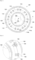
- FIG. 1 shows a superconducting motor 100 according to the invention in section through a plane perpendicular to the longitudinal axis X of the superconducting motor 100 and the Fig. 2 shows an enlargement of detail II.
- the superconducting motor 100 has generally the same structure as the superconducting motor 300 of the prior art.
- the superconducting motor 100 comprises a rotor 102 which is rotatable about the longitudinal axis X and which has a rotor core 104 made of a ferromagnetic material such as all iron alloys used for electrical machines.
- the rotor core 104 is cylindrical and coaxial with the longitudinal axis X and it has a central bore 106 in which a motor shaft 108 of said superconducting motor 100 is fitted and rigidly fixed.
- the motor shaft 108 is coaxial with the longitudinal axis X.
- the rotor 102 also comprises permanent magnets 110 fixed to the rotor core 104 on the periphery of the latter.
- the permanent magnets 110 are magnetized radially relative to the longitudinal axis X and in an alternating north-south manner from one to the other.
- the superconducting motor 100 comprises a stator 112 disposed outside the rotor 102 and comprising a stator core 114.
- the stator core 114 consists of two concentric cylinders coaxial with the longitudinal axis X, namely a support cylinder 114a and a magnetic cylinder 114b, where the support cylinder 114a is sleeved and fixed in the magnetic cylinder 114b.
- the magnetic cylinder 114b is made of a ferromagnetic material such as steel.
- the support cylinder 114a is made of a non-magnetic and electrically insulating material and serves as a support for coils 120 as explained below. According to a particular embodiment, the electrical conductivity of the support cylinder 114a is less than 1 S/m, and preferably less than 10 -6 S/m
- the support cylinder 114a is crossed by several orifices 116 (here sixteen in number) distributed angularly and regularly around the rotor 102 and they are even in number.
- the superconducting motor 100 includes a coil 120 that is wound while being housed in the orifices 116 of the pair.
- Each coil 120 is made of a superconducting material and is preferably made of a ribbon of a superconducting material wound on itself about a winding axis generally radial with respect to the longitudinal axis X.
- the hatching shown in the sections of the coils 120 shows layers of the ribbon.
- the rotor 102 and the stator 112 are housed in a motor housing 122 which is cylindrical and closed at its two ends by sides, at least one of which is pierced with a central orifice allowing the passage of the motor shaft 108.
- the stator 112 is mounted fixed inside the motor housing 122 while the rotor 102 and the motor shaft 108 are mounted free to rotate inside the motor housing 122.
- each coil 120 is electrically energized by an alternating current to generate a magnetic field that interacts with the permanent magnets 110 to drive them into rotation with the rotor 102 and the motor shaft 108.
- the superconducting motor 100 in the embodiment of the invention presented herein, comprises an inner cylinder 124 and an outer cylinder 126 which are coaxial with the longitudinal axis X.
- the inner cylinder 124 is arranged between the rotor 102 and the stator 112, i.e. here the support cylinder 114a, and the outer cylinder 126 is arranged around the stator 112, i.e. here the magnetic cylinder 114b, and inside the motor housing 122.
- the inner cylinder 124 and the outer cylinder 126 extend between the two flanks to which they are hermetically fixed to delimit between them (the two inner cylinders 124 and outer 126) and the two flanks, a chamber 128 in which the stator 112 is housed and which can be evacuated.
- the orifices 116 are in the vicinity of the outer periphery of the support cylinder 114a, and as shown in Figs. 1 and 2 , each orifice 116 opens at the level of the outer surface of the support cylinder 114a, that is to say opposite the magnetic cylinder 114b.
- each coil 120 is arranged in the vicinity of the magnetic cylinder 114b, that is to say on the outer periphery of the support cylinder 114a.
- the magnetic cylinder 114b has a recess 150 in depth inside the magnetic cylinder 114b. Each recess 150 extends angularly around the longitudinal axis X generally over the same angular extent as the orifice 116.
- the recess 150 is opposite the corresponding orifice 116. Between two successive recesses 150, the magnetic cylinder 114b has a tooth 118 which remains at a distance from the coil 120. Each coil 120 remains in the volume delimited by the support cylinder 114a and the teeth 118 remain beyond the support cylinder 114a and the coils 120.
- Each step 150 extends along the length of the magnetic cylinder 114b parallel to the longitudinal axis X.
- each recess 150 is arranged a cooling system 152 intended to cool the part of the coil 120 which is housed in the orifice 116 corresponding to the 150.
- the cooling system 152 is arranged outside the coils 120 relative to the longitudinal axis X and it interferes little with the magnetic field of the permanent magnets 110, hence better efficiency of the superconducting motor 100.
- Each cooling system 152 is thus surrounded on three sides by the magnetic cylinder 114b.
- the magnetic field created by the permanent magnets 110 is not deflected by the support cylinder 114a.
- the field lines 160 of the magnetic field created by the permanent magnets 110 are then generally parallel to the strips of the ribbon, which limits the performance losses.
- the magnetic field created by the permanent magnets 110 is deflected around the cooling system 152 due to the presence of the magnetic cylinder 114b which is around said cooling system 152. The influence of the magnetic cylinder 114b on the induced magnetic field (162) created by the coils 120 remains low.
- Each cooling system 152 is comprised of a plurality of tubes 154 which are arranged in the corresponding recess 150, i.e. outside the support cylinder 114a and the magnetic cylinder 114b, and the tubes 154 extend along the length of the magnetic cylinder 114b.
- These tubes 154 are fluidically connected to a source of a refrigerant fluid and the refrigerant fluid is then injected into the tubes 154 to cool the coils 120 which are opposite said tubes 154.
- the tubes 154 are made of a material having good thermal conductivity, for example metal such as copper alloy, to reduce the thermal gradient between the refrigerant fluid and the coils 120.
- the tubes 154 have good thermal conductivity greater than 10 W/mK and good electrical conductivity greater than 10 6 S/m.
Landscapes
- Engineering & Computer Science (AREA)
- Power Engineering (AREA)
- Superconductive Dynamoelectric Machines (AREA)
- Motor Or Generator Cooling System (AREA)
Abstract
Description
- La présente invention se rapporte au domaine général des moteurs supraconducteurs et plus particulièrement aux moteurs supraconducteurs comportant un système de refroidissement.
- La
Fig. 3 montre un moteur supraconducteur 300 de l'état de la technique où le moteur supraconducteur 300 est vu en coupe par un plan perpendiculaire à l'axe longitudinal X dudit moteur supraconducteur 300. - Le moteur supraconducteur 300 comporte un rotor 302 qui présente un coeur de rotor 304 réalisé dans un matériau ferromagnétique tel que l'ensemble des alliages de fer utilisés pour les machines électriques. Le coeur de rotor 304 est cylindrique et coaxial avec l'axe longitudinal X et il présente un alésage central 306 dans lequel est emmanché et fixé rigidement un arbre moteur 308 dudit moteur supraconducteur 300. L'arbre moteur 308 est coaxial avec l'axe longitudinal X.
- Le rotor 302 comporte également des aimants permanents 310 fixés au coeur de rotor 304 sur la périphérie de ce dernier. Il y a plusieurs aimants permanents 310 (ici au nombre de six) répartis angulairement et régulièrement autour du coeur de rotor 304 et espacés les uns des autres. Classiquement, les aimants permanents 310 sont magnétisés radialement par rapport à l'axe longitudinal X et de manière alternée de proche en proche.
- Le moteur supraconducteur 300 comporte un stator 312 disposé à l'extérieur du rotor 302 et comporte un coeur de stator 314 réalisé dans un matériau ferromagnétique tel que l'ensemble des alliages de fer utilisés pour les machines électriques. Le coeur de stator 314 prend une forme globalement cylindrique coaxiale avec l'axe longitudinal X.
- Au niveau de sa face cylindrique qui est orientée vers le rotor 302, le coeur de stator 314 présente des fentes 316 qui ici débouchent vers le rotor 302. Il y a plusieurs fentes 316 (ici au nombre de seize) réparties angulairement et régulièrement autour du rotor 302. Les fentes 316 sont agencées par paires et les deux fentes 316 de la paire sont séparées par une dent 318 monobloc et monomatière avec le coeur de stator 314.
- Pour chaque paire de fentes 316, le stator 312 comporte une bobine 320 qui est enroulée autour de la dent 318. Chaque bobine 320 est constituée d'un matériau supraconducteur.
- Le rotor 302 et le stator 312 sont classiquement logés dans un boîtier moteur 322 qui est cylindrique et fermé à ses deux extrémités par des flancs dont au moins un percé d'un orifice central permettant le passage de l'arbre moteur 308. Le stator 312 est monté fixe à l'intérieur du boîtier moteur 322 tandis que le rotor 302 et l'arbre moteur 308 sont montés libres en rotation à l'intérieur du boîtier moteur 322.
- En fonctionnement, chaque bobine 320 est alimentée électriquement pour générer un champ magnétique qui interagit avec les aimants permanents 310 pour les entraîner en rotation avec le rotor 302 et l'arbre moteur 308.
- Le moteur supraconducteur 300 comporte un cylindre intérieur 324 et un cylindre extérieur 326 qui sont coaxiaux avec l'axe longitudinal X.
- Le cylindre intérieur 324 est disposé entre le rotor 302 et le stator 312, et le cylindre extérieur 326 est disposé autour du stator 312 et à l'intérieur du boîtier moteur 322.
- Le cylindre intérieur 324 et le cylindre extérieur 326 s'étendent entre les deux flancs auxquels ils sont fixés hermétiquement pour délimiter entre eux et les deux flancs, une chambre 328 dans laquelle est logé le stator 312 et qui peut être mise au vide.
- Dans le cadre d'un moteur supraconducteur 300, les bobines 320 doivent être refroidies pour améliorer leur rendement. À cette fin, pour chaque fente 316, des tubes 330 sont disposés dans le fond de la fente 316 entre la bobine 320 logée dans la fente 316 et le coeur de stator 314. Ces tubes 330 sont fluidiquement connectés à une source d'un fluide réfrigérant. Le fluide réfrigérant est alors injecté dans les tubes 330 pour refroidir les bobines 320.
- Le champ magnétique créé par les aimants permanents 310 est dévié par le coeur de rotor 304 et le champ magnétique induit créé par les bobines 320 est intensifié sur les supraconducteurs par la présence des fentes 316, ce qui induit une dégradation dans le fonctionnement des bobines 320 et il est souhaitable de trouver un arrangement qui améliore le rendement du moteur supraconducteur.
- Un objet de la présente invention est de proposer un moteur supraconducteur comportant
- un rotor avec un coeur de rotor portant des aimants permanents et mobile en rotation autour d'un axe longitudinal,
- un stator disposé à l'extérieur du rotor et comportant un cylindre support et un cylindre magnétique, où le cylindre support est emmanché et fixé dans le cylindre magnétique, où le cylindre magnétique est réalisé dans un matériau ferromagnétique, où le cylindre support est réalisé dans un matériau amagnétique et isolant électrique, où le cylindre support est traversé par plusieurs orifices répartis angulairement et régulièrement autour du rotor, où pour chaque orifice, le cylindre magnétique présente un décrochement en profondeur à l'intérieur du cylindre magnétique et en face dudit orifice,
- pour chaque paire d'orifices, une bobine constituée d'un matériau supraconducteur qui est enroulée en étant logée dans les orifices de la paire, et
- pour chaque décrochement, un système de refroidissement arrangé dans ledit décrochement et destiné à refroidir la partie de la bobine qui est logée dans l'orifice correspondant au décrochement.
- Avec un tel arrangement, le rendement du moteur est amélioré.
- Avantageusement, chaque orifice débouche au niveau de la surface extérieure du cylindre support.
- Avantageusement, chaque bobine est constituée d'un ruban d'un matériau supraconducteur enroulé sur lui-même autour d'un axe d'enroulement globalement radial par rapport à l'axe longitudinal.
- Avantageusement, chaque système de refroidissement est constitué d'une pluralité de tubes disposés dans le décrochement correspondant, les tubes s'étendent sur la longueur du cylindre magnétique et ils sont destinés à être fluidiquement connectés à une source d'un fluide réfrigérant.
- Avantageusement, les tubes sont réalisés en métal.
- Les caractéristiques de l'invention mentionnées ci-dessus, ainsi que d'autres, apparaîtront plus clairement à la lecture de la description suivante d'un exemple de réalisation, ladite description étant faite en relation avec les dessins joints, parmi lesquels :
-
Fig. 1 est une vue en coupe d'un moteur supraconducteur selon l'invention, -
Fig. 2 est un agrandissement du détail II de laFig. 1 , et -
Fig. 3 est une vue en coupe d'un moteur supraconducteur de l'état de la technique. - La
Fig. 1 montre un moteur supraconducteur 100 selon l'invention en coupe par un plan perpendiculaire à l'axe longitudinal X du moteur supraconducteur 100 et laFig. 2 montre un agrandissement du détail II. Le moteur supraconducteur 100 présente globalement la même structure que le moteur supraconducteur 300 de l'état de la technique. - Le moteur supraconducteur 100 comporte un rotor 102 qui est mobile en rotation autour de l'axe longitudinal X et qui présente un coeur de rotor 104 réalisé dans un matériau ferromagnétique tel que l'ensemble des alliages de fer utilisés pour les machines électriques. Le coeur de rotor 104 est cylindrique et coaxial avec l'axe longitudinal X et il présente un alésage central 106 dans lequel est emmanché et fixé rigidement un arbre moteur 108 dudit moteur supraconducteur 100. L'arbre moteur 108 est coaxial avec l'axe longitudinal X.
- Le rotor 102 comporte également des aimants permanents 110 fixés au coeur de rotor 104 sur la périphérie de ce dernier. Il y a plusieurs aimants permanents 110 (ici au nombre de six) répartis angulairement et régulièrement autour du coeur de rotor 104 et espacés les uns des autres. Classiquement, les aimants permanents 110 sont magnétisés radialement par rapport à l'axe longitudinal X et de manière alternée nord-sud de proche en proche.
- Le moteur supraconducteur 100 comporte un stator 112 disposé à l'extérieur du rotor 102 et comportant un coeur de stator 114. Le coeur de stator 114 est constitué de deux cylindres concentriques coaxiaux avec l'axe longitudinal X, à savoir un cylindre support 114a et un cylindre magnétique 114b, où le cylindre support 114a est emmanché et fixé dans le cylindre magnétique 114b.
- Le cylindre magnétique 114b est réalisé dans un matériau ferromagnétique tel que de l'acier.
- Le cylindre support 114a est réalisé dans un matériau amagnétique et isolant électrique et sert de support à des bobines 120 comme cela est expliqué ci-dessous. Selon un mode de réalisation particulier, la conductivité électrique du cylindre support 114a est inférieure à 1 S/m, et de préférence inférieur à 10-6 S/m
- Le cylindre support 114a est traversé par plusieurs orifices 116 (ici au nombre de seize) répartis angulairement et régulièrement autour du rotor 102 et ils sont en nombre pair.
- Pour chaque paire d'orifices 116, le moteur supraconducteur 100 comporte une bobine 120 qui est enroulée en étant logée dans les orifices 116 de la paire. Chaque bobine 120 est constituée d'un matériau supraconducteur et est constituée préférentiellement d'un ruban d'un matériau supraconducteur enroulé sur lui-même autour d'un axe d'enroulement globalement radial par rapport à l'axe longitudinal X. Les hachures représentées dans les sections des bobines 120 montrent des couches du ruban.
- Dans le mode de réalisation de l'invention présenté ici, le rotor 102 et le stator 112 sont logés dans un boîtier moteur 122 qui est cylindrique et fermé à ses deux extrémités par des flancs dont au moins un percé d'un orifice central permettant le passage de l'arbre moteur 108. Le stator 112 est monté fixe à l'intérieur du boîtier moteur 122 tandis que le rotor 102 et l'arbre moteur 108 sont montés libres en rotation à l'intérieur du boîtier moteur 122.
- En fonctionnement, chaque bobine 120 est alimentée électriquement par un courant alternatif pour générer un champ magnétique qui interagit avec les aimants permanents 110 pour les entraîner en rotation avec le rotor 102 et l'arbre moteur 108.
- Comme pour le moteur supraconducteur 300 de l'état de la technique, le moteur supraconducteur 100, dans le mode de réalisation de l'invention présenté ici, comporte un cylindre intérieur 124 et un cylindre extérieur 126 qui sont coaxiaux avec l'axe longitudinal X.
- Le cylindre intérieur 124 est disposé entre le rotor 102 et le stator 112, c'est-à-dire ici le cylindre support 114a, et le cylindre extérieur 126 est disposé autour du stator 112, c'est-à-dire ici le cylindre magnétique 114b, et à l'intérieur du boîtier moteur 122.
- Le cylindre intérieur 124 et le cylindre extérieur 126 s'étendent entre les deux flancs auxquels ils sont fixés hermétiquement pour délimiter entre eux (les deux cylindres intérieur 124 et extérieur 126) et les deux flancs, une chambre 128 dans laquelle est logé le stator 112 et qui peut être mise au vide.
- Les orifices 116 sont au voisinage de la périphérie extérieure du cylindre support 114a, et comme le montrent les
Figs. 1 et 2 , chaque orifice 116 débouche au niveau de la surface extérieure du cylindre support 114a, c'est-à-dire en vis-à-vis du cylindre magnétique 114b. Ainsi, chaque bobine 120 est disposée au voisinage du cylindre magnétique 114b, c'est-à-dire sur la périphérie extérieure du cylindre support 114a. Pour chaque orifice 116, le cylindre magnétique 114b présente un décrochement 150 en profondeur à l'intérieur du cylindre magnétique 114b. Chaque décrochement 150 s'étend angulairement autour de l'axe longitudinal X globalement sur la même étendue angulaire que l'orifice 116. Le décrochement 150 est en face de l'orifice 116 correspondant. Entre deux décrochements 150 successifs, le cylindre magnétique 114b présente une dent 118 qui reste à distance de la bobine 120. Chaque bobine 120 reste dans le volume délimité par le cylindre support 114a et les dents 118 restent au-delà du cylindre support 114a et des bobines 120. - Chaque décrochement 150 s'étend sur la longueur du cylindre magnétique 114b parallèlement à l'axe longitudinal X.
- Dans chaque décrochement 150 est arrangé un système de refroidissement 152 destiné à refroidir la partie de la bobine 120 qui est logée dans l'orifice 116 correspondant au décrochement 150. Ainsi, le système de refroidissement 152 est disposé à l'extérieur des bobines 120 par rapport à l'axe longitudinal X et il interfère peu avec le champ magnétique des aimants permanents 110 d'où un meilleur rendement du moteur supraconducteur 100. Chaque système de refroidissement 152 est ainsi cerné sur trois côtés par le cylindre magnétique 114b.
- Le champ magnétique créé par les aimants permanents 110 n'est pas dévié par le cylindre support 114a. Dans le cas de bobines 120 constituées d'un enroulement d'un ruban tel que cela est expliqué ci-dessus, les lignes 160 de champ du champ magnétique créé par les aimants permanents 110 sont alors globalement parallèles aux bandes du ruban, ce qui limite les pertes de performances. En outre, le champ magnétique créé par les aimants permanents 110 est dévié autour du système de refroidissement 152 du fait de la présence du cylindre magnétique 114b qui est autour dudit système de refroidissement 152. L'influence du cylindre magnétique 114b sur le champ magnétique (162) induit créé par les bobines 120 reste faible.
- Tous ces éléments permettent d'avoir encore un meilleur rendement.
- Chaque système de refroidissement 152 est constitué d'une pluralité de tubes 154 qui sont disposés dans le décrochement 150 correspondant, c'est-à-dire en dehors du cylindre support 114a et du cylindre magnétique 114b, et les tubes 154 s'étendent sur la longueur du cylindre magnétique 114b. Ces tubes 154 sont fluidiquement connectés à une source d'un fluide réfrigérant et le fluide réfrigérant est alors injecté dans les tubes 154 pour refroidir les bobines 120 qui sont en face desdits tubes 154.
- Les tubes 154 sont réalisés dans un matériau présentant une bonne conductivité thermique, par exemple en métal comme de l'alliage de cuivre, pour réduire le gradient thermique entre le fluide réfrigérant et les bobines 120.
- Selon un mode de réalisation particulier, les tubes 154 présentent une bonne conductivité thermique supérieure à 10W/m.K et une bonne conductivité électriques supérieure à 106 S/m.
Claims (5)
- Moteur supraconducteur (100) comportant :- un rotor (102) avec un coeur de rotor (104) portant des aimants permanents (110) et mobile en rotation autour d'un axe longitudinal (X),- un stator (112) disposé à l'extérieur du rotor (102) et comportant un cylindre support (114a) et un cylindre magnétique (114b), où le cylindre support (114a) est emmanché et fixé dans le cylindre magnétique (114b), où le cylindre magnétique (114b) est réalisé dans un matériau ferromagnétique, où le cylindre support (114a) est réalisé dans un matériau amagnétique et isolant électrique, où le cylindre support (114a) est traversé par plusieurs orifices (116) répartis angulairement et régulièrement autour du rotor (102), où pour chaque orifice (116), le cylindre magnétique (114b) présente un décrochement (150) en profondeur à l'intérieur du cylindre magnétique (114b) et en face dudit orifice (116),- pour chaque paire d'orifices (116), une bobine (120) constituée d'un matériau supraconducteur qui est enroulée en étant logée dans les orifices (116) de la paire, et- pour chaque décrochement (150), un système de refroidissement (152) arrangé dans ledit décrochement (150) et destiné à refroidir la partie de la bobine (120) qui est logée dans l'orifice (116) correspondant au décrochement (150).
- Moteur supraconducteur (100) selon la revendication 1, caractérisé en ce que chaque orifice (116) débouche au niveau de la surface extérieure du cylindre support (114a).
- Moteur supraconducteur (100) selon l'une des revendications 1 ou 2, caractérisé en ce que chaque bobine (120) est constituée d'un ruban d'un matériau supraconducteur enroulé sur lui-même autour d'un axe d'enroulement globalement radial par rapport à l'axe longitudinal (X).
- Moteur supraconducteur (100) selon l'une des revendications 1 à 3, caractérisé en ce que chaque système de refroidissement (152) est constitué d'une pluralité de tubes (154) disposés dans le décrochement (150) correspondant, en ce que les tubes (154) s'étendent sur la longueur du cylindre magnétique (114b) et ils sont destinés à être fluidiquement connectés à une source d'un fluide réfrigérant.
- Moteur supraconducteur (100) selon la revendication 4, caractérisé en ce que les tubes (154) sont réalisés en métal.
Applications Claiming Priority (1)
| Application Number | Priority Date | Filing Date | Title |
|---|---|---|---|
| FR2301800 | 2023-02-27 |
Publications (2)
| Publication Number | Publication Date |
|---|---|
| EP4422042A1 true EP4422042A1 (fr) | 2024-08-28 |
| EP4422042B1 EP4422042B1 (fr) | 2025-10-15 |
Family
ID=86329512
Family Applications (1)
| Application Number | Title | Priority Date | Filing Date |
|---|---|---|---|
| EP24159548.7A Active EP4422042B1 (fr) | 2023-02-27 | 2024-02-26 | Moteur supraconducteur comportant un système de refroidissement |
Country Status (3)
| Country | Link |
|---|---|
| US (1) | US20240291370A1 (fr) |
| EP (1) | EP4422042B1 (fr) |
| CN (1) | CN118554722A (fr) |
Cited By (1)
| Publication number | Priority date | Publication date | Assignee | Title |
|---|---|---|---|---|
| FR3166770A1 (fr) * | 2024-09-20 | 2026-03-27 | Airbus (S.A.S.) | Système de bobine pour un moteur supraconducteur |
Citations (5)
| Publication number | Priority date | Publication date | Assignee | Title |
|---|---|---|---|---|
| US20010035692A1 (en) * | 2000-04-25 | 2001-11-01 | Ong Raymond K.J. | Stator, dynamoelectric machine, and methods for fabricating same |
| US20120161557A1 (en) * | 2010-12-28 | 2012-06-28 | Aisin Seiki Kabushiki Kaisha | Superconducting electric motor |
| KR20140134794A (ko) * | 2013-05-14 | 2014-11-25 | 두산중공업 주식회사 | 고정자 및 그것을 포함하는 초전도 회전기기 |
| JP2016149485A (ja) * | 2015-02-13 | 2016-08-18 | 住友電気工業株式会社 | 超電導機器 |
| US20200076260A1 (en) * | 2018-08-08 | 2020-03-05 | Oswald Elektromotoren Gmbh | Machine coil for an electric machine |
Family Cites Families (1)
| Publication number | Priority date | Publication date | Assignee | Title |
|---|---|---|---|---|
| US7211919B2 (en) * | 1999-08-16 | 2007-05-01 | American Superconductor Corporation | Thermally-conductive stator support structure |
-
2024
- 2024-02-23 US US18/585,341 patent/US20240291370A1/en active Pending
- 2024-02-26 CN CN202410208324.8A patent/CN118554722A/zh active Pending
- 2024-02-26 EP EP24159548.7A patent/EP4422042B1/fr active Active
Patent Citations (5)
| Publication number | Priority date | Publication date | Assignee | Title |
|---|---|---|---|---|
| US20010035692A1 (en) * | 2000-04-25 | 2001-11-01 | Ong Raymond K.J. | Stator, dynamoelectric machine, and methods for fabricating same |
| US20120161557A1 (en) * | 2010-12-28 | 2012-06-28 | Aisin Seiki Kabushiki Kaisha | Superconducting electric motor |
| KR20140134794A (ko) * | 2013-05-14 | 2014-11-25 | 두산중공업 주식회사 | 고정자 및 그것을 포함하는 초전도 회전기기 |
| JP2016149485A (ja) * | 2015-02-13 | 2016-08-18 | 住友電気工業株式会社 | 超電導機器 |
| US20200076260A1 (en) * | 2018-08-08 | 2020-03-05 | Oswald Elektromotoren Gmbh | Machine coil for an electric machine |
Cited By (1)
| Publication number | Priority date | Publication date | Assignee | Title |
|---|---|---|---|---|
| FR3166770A1 (fr) * | 2024-09-20 | 2026-03-27 | Airbus (S.A.S.) | Système de bobine pour un moteur supraconducteur |
Also Published As
| Publication number | Publication date |
|---|---|
| EP4422042B1 (fr) | 2025-10-15 |
| CN118554722A (zh) | 2024-08-27 |
| US20240291370A1 (en) | 2024-08-29 |
Similar Documents
| Publication | Publication Date | Title |
|---|---|---|
| EP2002531B1 (fr) | Moteur electrique polyphase notamment pour l'entrainement de pompes ou de ventilateurs | |
| FR2994353A1 (fr) | Moteur electrique optimise a dents etroites | |
| EP1001507A1 (fr) | Machine électrique dont le rotor est spécialement adapté aux hautes vitesses | |
| EP4422042B1 (fr) | Moteur supraconducteur comportant un système de refroidissement | |
| FR2941106A1 (fr) | Machine electrique tournante a poles saillants | |
| FR3006124A1 (fr) | Rotor de machine electrique a flux axial et machine electrique correspondante | |
| FR3086121A1 (fr) | Rotor pour machine electrique asynchrone a arbre non traversant | |
| WO2019037930A1 (fr) | Machine electrique avec dispositif de refroidissement comprenant un canal partiellement subdivise | |
| WO2017149434A1 (fr) | Procede pour generer un champ magnetique et generateur de champ magnetique | |
| FR2941105A1 (fr) | Machine electrique tournante,en particulier pour un demarreur de vehicule automobile | |
| WO1983001541A1 (fr) | Machine electrique synchrone a inducteur supraconducteur | |
| FR3082373A1 (fr) | Stator de machine electrique tournante | |
| FR3100399A1 (fr) | Machine à bobinage toroïdal | |
| FR3077414A1 (fr) | Aimant unitaire a configuration ovoide et structure d'aimant a plusieurs aimants unitaires | |
| WO2020174158A1 (fr) | Bobine de machine electrique a refroidissement ameliore | |
| WO1989012346A1 (fr) | Moteur electrique synchrone di- ou polyphase a rotor en forme de disque | |
| WO2025140999A1 (fr) | Stator de moteur électrique comportant un système de refroidissement des dents | |
| FR2710466A1 (fr) | Rotor de machine synchrone. | |
| EP1174986A1 (fr) | Rotor feuilleté pour frein à courants de Foucault et dispositif comportant un tel rotor | |
| FR2986919A1 (fr) | Moteur electrique a grande vitesse | |
| FR3150362A1 (fr) | Stator pour un moteur supraconducteur | |
| WO2020193297A1 (fr) | Rotor de machine electrique avec moyen de ventilation axialo-centrifuge | |
| FR3166770A1 (fr) | Système de bobine pour un moteur supraconducteur | |
| FR2578117A1 (fr) | Rotor pour machine electrique rotative supraconductrice | |
| EP3758198A1 (fr) | Machine electrique tournante munie d'ailettes de refroidissement |
Legal Events
| Date | Code | Title | Description |
|---|---|---|---|
| PUAI | Public reference made under article 153(3) epc to a published international application that has entered the european phase |
Free format text: ORIGINAL CODE: 0009012 |
|
| STAA | Information on the status of an ep patent application or granted ep patent |
Free format text: STATUS: THE APPLICATION HAS BEEN PUBLISHED |
|
| AK | Designated contracting states |
Kind code of ref document: A1 Designated state(s): AL AT BE BG CH CY CZ DE DK EE ES FI FR GB GR HR HU IE IS IT LI LT LU LV MC ME MK MT NL NO PL PT RO RS SE SI SK SM TR |
|
| STAA | Information on the status of an ep patent application or granted ep patent |
Free format text: STATUS: REQUEST FOR EXAMINATION WAS MADE |
|
| 17P | Request for examination filed |
Effective date: 20250226 |
|
| GRAP | Despatch of communication of intention to grant a patent |
Free format text: ORIGINAL CODE: EPIDOSNIGR1 |
|
| STAA | Information on the status of an ep patent application or granted ep patent |
Free format text: STATUS: GRANT OF PATENT IS INTENDED |
|
| INTG | Intention to grant announced |
Effective date: 20250512 |
|
| GRAS | Grant fee paid |
Free format text: ORIGINAL CODE: EPIDOSNIGR3 |
|
| GRAA | (expected) grant |
Free format text: ORIGINAL CODE: 0009210 |
|
| STAA | Information on the status of an ep patent application or granted ep patent |
Free format text: STATUS: THE PATENT HAS BEEN GRANTED |
|
| AK | Designated contracting states |
Kind code of ref document: B1 Designated state(s): AL AT BE BG CH CY CZ DE DK EE ES FI FR GB GR HR HU IE IS IT LI LT LU LV MC ME MK MT NL NO PL PT RO RS SE SI SK SM TR |
|
| REG | Reference to a national code |
Ref country code: GB Ref legal event code: FG4D Free format text: NOT ENGLISH Ref country code: CH Ref legal event code: F10 Free format text: ST27 STATUS EVENT CODE: U-0-0-F10-F00 (AS PROVIDED BY THE NATIONAL OFFICE) Effective date: 20251015 |
|
| REG | Reference to a national code |
Ref country code: IE Ref legal event code: FG4D Free format text: LANGUAGE OF EP DOCUMENT: FRENCH |
|
| REG | Reference to a national code |
Ref country code: DE Ref legal event code: R096 Ref document number: 602024000890 Country of ref document: DE |
|
| REG | Reference to a national code |
Ref country code: NL Ref legal event code: MP Effective date: 20251015 |
|
| REG | Reference to a national code |
Ref country code: AT Ref legal event code: MK05 Ref document number: 1847928 Country of ref document: AT Kind code of ref document: T Effective date: 20251015 |
|
| PG25 | Lapsed in a contracting state [announced via postgrant information from national office to epo] |
Ref country code: NL Free format text: LAPSE BECAUSE OF FAILURE TO SUBMIT A TRANSLATION OF THE DESCRIPTION OR TO PAY THE FEE WITHIN THE PRESCRIBED TIME-LIMIT Effective date: 20251015 |
|
| PG25 | Lapsed in a contracting state [announced via postgrant information from national office to epo] |
Ref country code: ES Free format text: LAPSE BECAUSE OF FAILURE TO SUBMIT A TRANSLATION OF THE DESCRIPTION OR TO PAY THE FEE WITHIN THE PRESCRIBED TIME-LIMIT Effective date: 20251015 |
|
| REG | Reference to a national code |
Ref country code: LT Ref legal event code: MG9D |
|
| PG25 | Lapsed in a contracting state [announced via postgrant information from national office to epo] |
Ref country code: NO Free format text: LAPSE BECAUSE OF FAILURE TO SUBMIT A TRANSLATION OF THE DESCRIPTION OR TO PAY THE FEE WITHIN THE PRESCRIBED TIME-LIMIT Effective date: 20260115 |
|
| PGFP | Annual fee paid to national office [announced via postgrant information from national office to epo] |
Ref country code: DE Payment date: 20260218 Year of fee payment: 3 |
|
| PG25 | Lapsed in a contracting state [announced via postgrant information from national office to epo] |
Ref country code: FI Free format text: LAPSE BECAUSE OF FAILURE TO SUBMIT A TRANSLATION OF THE DESCRIPTION OR TO PAY THE FEE WITHIN THE PRESCRIBED TIME-LIMIT Effective date: 20251015 Ref country code: HR Free format text: LAPSE BECAUSE OF FAILURE TO SUBMIT A TRANSLATION OF THE DESCRIPTION OR TO PAY THE FEE WITHIN THE PRESCRIBED TIME-LIMIT Effective date: 20251015 Ref country code: AT Free format text: LAPSE BECAUSE OF FAILURE TO SUBMIT A TRANSLATION OF THE DESCRIPTION OR TO PAY THE FEE WITHIN THE PRESCRIBED TIME-LIMIT Effective date: 20251015 |
|
| PG25 | Lapsed in a contracting state [announced via postgrant information from national office to epo] |
Ref country code: RS Free format text: LAPSE BECAUSE OF FAILURE TO SUBMIT A TRANSLATION OF THE DESCRIPTION OR TO PAY THE FEE WITHIN THE PRESCRIBED TIME-LIMIT Effective date: 20260115 |
|
| PG25 | Lapsed in a contracting state [announced via postgrant information from national office to epo] |
Ref country code: IS Free format text: LAPSE BECAUSE OF FAILURE TO SUBMIT A TRANSLATION OF THE DESCRIPTION OR TO PAY THE FEE WITHIN THE PRESCRIBED TIME-LIMIT Effective date: 20260215 |
|
| PGFP | Annual fee paid to national office [announced via postgrant information from national office to epo] |
Ref country code: FR Payment date: 20260219 Year of fee payment: 3 |
|
| PG25 | Lapsed in a contracting state [announced via postgrant information from national office to epo] |
Ref country code: PT Free format text: LAPSE BECAUSE OF FAILURE TO SUBMIT A TRANSLATION OF THE DESCRIPTION OR TO PAY THE FEE WITHIN THE PRESCRIBED TIME-LIMIT Effective date: 20260216 |
|
| PG25 | Lapsed in a contracting state [announced via postgrant information from national office to epo] |
Ref country code: PL Free format text: LAPSE BECAUSE OF FAILURE TO SUBMIT A TRANSLATION OF THE DESCRIPTION OR TO PAY THE FEE WITHIN THE PRESCRIBED TIME-LIMIT Effective date: 20251015 |
|
| PG25 | Lapsed in a contracting state [announced via postgrant information from national office to epo] |
Ref country code: LV Free format text: LAPSE BECAUSE OF FAILURE TO SUBMIT A TRANSLATION OF THE DESCRIPTION OR TO PAY THE FEE WITHIN THE PRESCRIBED TIME-LIMIT Effective date: 20251015 |
|
| PG25 | Lapsed in a contracting state [announced via postgrant information from national office to epo] |
Ref country code: BG Free format text: LAPSE BECAUSE OF FAILURE TO SUBMIT A TRANSLATION OF THE DESCRIPTION OR TO PAY THE FEE WITHIN THE PRESCRIBED TIME-LIMIT Effective date: 20251015 |
|
| PG25 | Lapsed in a contracting state [announced via postgrant information from national office to epo] |
Ref country code: LT Free format text: LAPSE BECAUSE OF FAILURE TO SUBMIT A TRANSLATION OF THE DESCRIPTION OR TO PAY THE FEE WITHIN THE PRESCRIBED TIME-LIMIT Effective date: 20251015 |
|
| PG25 | Lapsed in a contracting state [announced via postgrant information from national office to epo] |
Ref country code: SM Free format text: LAPSE BECAUSE OF FAILURE TO SUBMIT A TRANSLATION OF THE DESCRIPTION OR TO PAY THE FEE WITHIN THE PRESCRIBED TIME-LIMIT Effective date: 20251015 |
|
| PG25 | Lapsed in a contracting state [announced via postgrant information from national office to epo] |
Ref country code: DK Free format text: LAPSE BECAUSE OF FAILURE TO SUBMIT A TRANSLATION OF THE DESCRIPTION OR TO PAY THE FEE WITHIN THE PRESCRIBED TIME-LIMIT Effective date: 20251015 |
|
| PG25 | Lapsed in a contracting state [announced via postgrant information from national office to epo] |
Ref country code: IT Free format text: LAPSE BECAUSE OF FAILURE TO SUBMIT A TRANSLATION OF THE DESCRIPTION OR TO PAY THE FEE WITHIN THE PRESCRIBED TIME-LIMIT Effective date: 20251015 |
|
| PG25 | Lapsed in a contracting state [announced via postgrant information from national office to epo] |
Ref country code: EE Free format text: LAPSE BECAUSE OF FAILURE TO SUBMIT A TRANSLATION OF THE DESCRIPTION OR TO PAY THE FEE WITHIN THE PRESCRIBED TIME-LIMIT Effective date: 20251015 |
|
| PG25 | Lapsed in a contracting state [announced via postgrant information from national office to epo] |
Ref country code: CZ Free format text: LAPSE BECAUSE OF FAILURE TO SUBMIT A TRANSLATION OF THE DESCRIPTION OR TO PAY THE FEE WITHIN THE PRESCRIBED TIME-LIMIT Effective date: 20251015 |
|
| PG25 | Lapsed in a contracting state [announced via postgrant information from national office to epo] |
Ref country code: SK Free format text: LAPSE BECAUSE OF FAILURE TO SUBMIT A TRANSLATION OF THE DESCRIPTION OR TO PAY THE FEE WITHIN THE PRESCRIBED TIME-LIMIT Effective date: 20251015 |
|
| PG25 | Lapsed in a contracting state [announced via postgrant information from national office to epo] |
Ref country code: SE Free format text: LAPSE BECAUSE OF FAILURE TO SUBMIT A TRANSLATION OF THE DESCRIPTION OR TO PAY THE FEE WITHIN THE PRESCRIBED TIME-LIMIT Effective date: 20251015 |