EP4422019A1 - Controller for managing charging or discharging of heterogeneous battery pack, system, and method - Google Patents
Controller for managing charging or discharging of heterogeneous battery pack, system, and method Download PDFInfo
- Publication number
- EP4422019A1 EP4422019A1 EP22882212.8A EP22882212A EP4422019A1 EP 4422019 A1 EP4422019 A1 EP 4422019A1 EP 22882212 A EP22882212 A EP 22882212A EP 4422019 A1 EP4422019 A1 EP 4422019A1
- Authority
- EP
- European Patent Office
- Prior art keywords
- battery pack
- power
- battery
- battery packs
- charge
- Prior art date
- Legal status (The legal status is an assumption and is not a legal conclusion. Google has not performed a legal analysis and makes no representation as to the accuracy of the status listed.)
- Pending
Links
Images







Classifications
-
- H—ELECTRICITY
- H02—GENERATION; CONVERSION OR DISTRIBUTION OF ELECTRIC POWER
- H02J—ELECTRIC POWER NETWORKS; CIRCUIT ARRANGEMENTS OR SYSTEMS FOR SUPPLYING OR DISTRIBUTING ELECTRIC POWER; SYSTEMS FOR STORING ELECTRIC ENERGY
- H02J7/00—Circuit arrangements for charging or discharging batteries or for supplying loads from batteries
- H02J7/40—Circuit arrangements for charging or discharging batteries or for supplying loads from batteries characterised by the exchange of charge or discharge related data
-
- H—ELECTRICITY
- H02—GENERATION; CONVERSION OR DISTRIBUTION OF ELECTRIC POWER
- H02J—ELECTRIC POWER NETWORKS; CIRCUIT ARRANGEMENTS OR SYSTEMS FOR SUPPLYING OR DISTRIBUTING ELECTRIC POWER; SYSTEMS FOR STORING ELECTRIC ENERGY
- H02J7/00—Circuit arrangements for charging or discharging batteries or for supplying loads from batteries
- H02J7/90—Regulation of charging or discharging current or voltage
- H02J7/96—Regulation of charging or discharging current or voltage in response to battery voltage
-
- H—ELECTRICITY
- H01—ELECTRIC ELEMENTS
- H01M—PROCESSES OR MEANS, e.g. BATTERIES, FOR THE DIRECT CONVERSION OF CHEMICAL ENERGY INTO ELECTRICAL ENERGY
- H01M10/00—Secondary cells; Manufacture thereof
- H01M10/42—Methods or arrangements for servicing or maintenance of secondary cells or secondary half-cells
- H01M10/425—Structural combination with electronic components, e.g. electronic circuits integrated to the outside of the casing
-
- H—ELECTRICITY
- H01—ELECTRIC ELEMENTS
- H01M—PROCESSES OR MEANS, e.g. BATTERIES, FOR THE DIRECT CONVERSION OF CHEMICAL ENERGY INTO ELECTRICAL ENERGY
- H01M10/00—Secondary cells; Manufacture thereof
- H01M10/42—Methods or arrangements for servicing or maintenance of secondary cells or secondary half-cells
- H01M10/44—Methods for charging or discharging
- H01M10/441—Methods for charging or discharging for several batteries or cells simultaneously or sequentially
-
- H—ELECTRICITY
- H01—ELECTRIC ELEMENTS
- H01M—PROCESSES OR MEANS, e.g. BATTERIES, FOR THE DIRECT CONVERSION OF CHEMICAL ENERGY INTO ELECTRICAL ENERGY
- H01M10/00—Secondary cells; Manufacture thereof
- H01M10/42—Methods or arrangements for servicing or maintenance of secondary cells or secondary half-cells
- H01M10/48—Accumulators combined with arrangements for measuring, testing or indicating the condition of cells, e.g. the level or density of the electrolyte
- H01M10/482—Accumulators combined with arrangements for measuring, testing or indicating the condition of cells, e.g. the level or density of the electrolyte for several batteries or cells simultaneously or sequentially
-
- H—ELECTRICITY
- H01—ELECTRIC ELEMENTS
- H01M—PROCESSES OR MEANS, e.g. BATTERIES, FOR THE DIRECT CONVERSION OF CHEMICAL ENERGY INTO ELECTRICAL ENERGY
- H01M10/00—Secondary cells; Manufacture thereof
- H01M10/54—Reclaiming serviceable parts of waste accumulators
-
- H—ELECTRICITY
- H02—GENERATION; CONVERSION OR DISTRIBUTION OF ELECTRIC POWER
- H02J—ELECTRIC POWER NETWORKS; CIRCUIT ARRANGEMENTS OR SYSTEMS FOR SUPPLYING OR DISTRIBUTING ELECTRIC POWER; SYSTEMS FOR STORING ELECTRIC ENERGY
- H02J3/00—Circuit arrangements for AC mains or AC distribution networks
- H02J3/003—Load forecast, e.g. methods or systems for forecasting future load demand
-
- H—ELECTRICITY
- H02—GENERATION; CONVERSION OR DISTRIBUTION OF ELECTRIC POWER
- H02J—ELECTRIC POWER NETWORKS; CIRCUIT ARRANGEMENTS OR SYSTEMS FOR SUPPLYING OR DISTRIBUTING ELECTRIC POWER; SYSTEMS FOR STORING ELECTRIC ENERGY
- H02J3/00—Circuit arrangements for AC mains or AC distribution networks
- H02J3/28—Arrangements for balancing of the load in networks by storage of energy
- H02J3/32—Arrangements for balancing of the load in networks by storage of energy using batteries or super capacitors with converting means
-
- H—ELECTRICITY
- H02—GENERATION; CONVERSION OR DISTRIBUTION OF ELECTRIC POWER
- H02J—ELECTRIC POWER NETWORKS; CIRCUIT ARRANGEMENTS OR SYSTEMS FOR SUPPLYING OR DISTRIBUTING ELECTRIC POWER; SYSTEMS FOR STORING ELECTRIC ENERGY
- H02J7/00—Circuit arrangements for charging or discharging batteries or for supplying loads from batteries
- H02J7/40—Circuit arrangements for charging or discharging batteries or for supplying loads from batteries characterised by the exchange of charge or discharge related data
- H02J7/44—Circuit arrangements for charging or discharging batteries or for supplying loads from batteries characterised by the exchange of charge or discharge related data between battery management systems and power sources
-
- H—ELECTRICITY
- H02—GENERATION; CONVERSION OR DISTRIBUTION OF ELECTRIC POWER
- H02J—ELECTRIC POWER NETWORKS; CIRCUIT ARRANGEMENTS OR SYSTEMS FOR SUPPLYING OR DISTRIBUTING ELECTRIC POWER; SYSTEMS FOR STORING ELECTRIC ENERGY
- H02J7/00—Circuit arrangements for charging or discharging batteries or for supplying loads from batteries
- H02J7/50—Circuit arrangements for charging or discharging batteries or for supplying loads from batteries acting upon multiple batteries simultaneously or sequentially
-
- H—ELECTRICITY
- H02—GENERATION; CONVERSION OR DISTRIBUTION OF ELECTRIC POWER
- H02J—ELECTRIC POWER NETWORKS; CIRCUIT ARRANGEMENTS OR SYSTEMS FOR SUPPLYING OR DISTRIBUTING ELECTRIC POWER; SYSTEMS FOR STORING ELECTRIC ENERGY
- H02J7/00—Circuit arrangements for charging or discharging batteries or for supplying loads from batteries
- H02J7/50—Circuit arrangements for charging or discharging batteries or for supplying loads from batteries acting upon multiple batteries simultaneously or sequentially
- H02J7/585—Sequential battery discharge in systems with a plurality of batteries
-
- H—ELECTRICITY
- H02—GENERATION; CONVERSION OR DISTRIBUTION OF ELECTRIC POWER
- H02J—ELECTRIC POWER NETWORKS; CIRCUIT ARRANGEMENTS OR SYSTEMS FOR SUPPLYING OR DISTRIBUTING ELECTRIC POWER; SYSTEMS FOR STORING ELECTRIC ENERGY
- H02J7/00—Circuit arrangements for charging or discharging batteries or for supplying loads from batteries
- H02J7/80—Circuit arrangements for charging or discharging batteries or for supplying loads from batteries including monitoring or indicating arrangements
-
- H—ELECTRICITY
- H02—GENERATION; CONVERSION OR DISTRIBUTION OF ELECTRIC POWER
- H02J—ELECTRIC POWER NETWORKS; CIRCUIT ARRANGEMENTS OR SYSTEMS FOR SUPPLYING OR DISTRIBUTING ELECTRIC POWER; SYSTEMS FOR STORING ELECTRIC ENERGY
- H02J7/00—Circuit arrangements for charging or discharging batteries or for supplying loads from batteries
- H02J7/80—Circuit arrangements for charging or discharging batteries or for supplying loads from batteries including monitoring or indicating arrangements
- H02J7/82—Control of state of charge [SOC]
-
- H—ELECTRICITY
- H02—GENERATION; CONVERSION OR DISTRIBUTION OF ELECTRIC POWER
- H02J—ELECTRIC POWER NETWORKS; CIRCUIT ARRANGEMENTS OR SYSTEMS FOR SUPPLYING OR DISTRIBUTING ELECTRIC POWER; SYSTEMS FOR STORING ELECTRIC ENERGY
- H02J7/00—Circuit arrangements for charging or discharging batteries or for supplying loads from batteries
- H02J7/80—Circuit arrangements for charging or discharging batteries or for supplying loads from batteries including monitoring or indicating arrangements
- H02J7/84—Control of state of health [SOH]
-
- H—ELECTRICITY
- H01—ELECTRIC ELEMENTS
- H01M—PROCESSES OR MEANS, e.g. BATTERIES, FOR THE DIRECT CONVERSION OF CHEMICAL ENERGY INTO ELECTRICAL ENERGY
- H01M10/00—Secondary cells; Manufacture thereof
- H01M10/42—Methods or arrangements for servicing or maintenance of secondary cells or secondary half-cells
- H01M10/425—Structural combination with electronic components, e.g. electronic circuits integrated to the outside of the casing
- H01M2010/4271—Battery management systems including electronic circuits, e.g. control of current or voltage to keep battery in healthy state, cell balancing
-
- H—ELECTRICITY
- H01—ELECTRIC ELEMENTS
- H01M—PROCESSES OR MEANS, e.g. BATTERIES, FOR THE DIRECT CONVERSION OF CHEMICAL ENERGY INTO ELECTRICAL ENERGY
- H01M2220/00—Batteries for particular applications
- H01M2220/20—Batteries in motive systems, e.g. vehicle, ship, plane
Definitions
- the disclosure relates to systems and methods for controlling or managing battery packs generally. More particularly, the disclosed subject matter relates to a controller, a system, and a method for managing discharge or charge of battery packs, for example, in energy storage application.
- a stationary energy storage system can store energy and release energy in the form of electricity when it is needed.
- the present disclosure provides a controller for controlling or managing discharge or charge of heterogeneous battery packs, a system such as an electrical energy storage system comprising such a controller, and methods of using the same.
- the controller, the system, and the method utilize a technique of ranking a plurality of battery packs based on a voltage distribution parameter of each battery pack.
- the ranking order of the plurality of battery packs is used as an order for discharging power from the system or charging power to the system.
- a system comprises a plurality of battery packs, one or more power converters, and one or more controller.
- Each power converter is coupled with at least one of the plurality of battery packs, and is configured to convert direct current (DC) from one battery pack to alternating current (AC) or vice versa.
- the controller is coupled to the plurality of battery packs and the one or more power converters.
- the system may also include more than one controller, and each controller is coupled to a plurality of battery packs.
- the plurality of battery packs are defined and described herein.
- the plurality packs are heterogeneous battery packs, which can be selected from new batteries, second-use electric vehicle (EV) batteries, or combinations thereof.
- the plurality of battery packs are connected in parallel, in series, or in a combination (i.e. hybrid combinations) thereof. In some embodiments, the plurality of battery packs are connected in parallel.
- the controller comprises one or more processors and at least one tangible, non-transitory machine readable medium encoded with one or more programs configured to perform steps for controlling or managing a discharging process or a charging process of the system having the plurality of battery packs.
- these steps include: receiving a total power demand (D) (or called total dispatch power) needed to be dispatched from the system or to be charged to the system, and collecting characteristic data of each battery pack.
- the characteristic data of each battery pack include a maximum voltage (V i max ), a minimum voltage for discharge (V i min ), and a present voltage (V i ).
- the characteristic data may also include a maximum total rated power (d i max ) of each battery, state of health (SOH), and/or state of charge (SOC).
- the steps further include determining a voltage distribution parameter (V i *) of each battery pack based on V i max , V i min , and V i .
- the steps also include ranking the plurality of battery packs by assigning a rank to each battery pack as an order for discharging or charging based on the voltage distribution parameter (V i *) for each battery pack, and determining a respective power discharge or charge for each battery pack based on the rank of each battery pack and the total power demand (D).
- the steps also further include providing signals with instructions to the plurality of battery packs and the one or more power converters for discharging power from or charging power to the plurality of battery packs based on the respective discharge power of each battery pack and/or keeping a certain battery pack idle.
- the controller is configured to rank the plurality of battery packs in an increasing order, a decreasing order, or a random order of the voltage distribution parameter (V i* ) of each battery pack.
- the power is discharged or charged in the increasing order, the decreasing order, or the random order of the voltage distribution parameter (V i* ), respectively.
- the controller is configured to determine the respective power discharge or charge for each battery by assigning the respective power discharge or charge based on a respective maximum total rated power (d i max ) of each battery pack in the order for discharging or charging until the total power demand (D) is reached. After the total power demand is satisfied, other battery packs with lower ranks may not be assigned for discharging or charging, and the respective power discharge or charge is zero. When the respective power discharge or charge of a certain battery pack is zero, the specific battery pack is kept idle without discharging or charging.
- the controller is configured to provide the signal with instructions for a pre-determined time interval, and re-determine the respective power discharge or charge for each battery pack after the time interval ends or when a voltage collapse occurs to a battery pack, by repeating the steps described above.
- the controller may be configured to dynamically control discharging or charging of the plurality of battery packs by updating the respective power discharge or charge of each battery pack instantaneously with time.
- the system may optionally further comprise one or more battery power management unit (BPMU).
- BPMU battery power management unit
- Each BPMU may be connected with one or more battery packs, and is configured to monitor the one or more battery packs and provide characteristic data of the one or more battery packs to the controller.
- the system is an electrical energy storage system.
- the total power demand is provided from an upper level energy management system (EMS).
- EMS energy management system
- the controller is configured to discharge power from the plurality of battery packs to a grid or load or charge power from the grid or load to the plurality of battery packs.
- the grid is optional. The power can be discharged to other components, in which electrical power is needed.
- the present disclosure provides a controller as described herein for controlling or managing discharge or charge of a system comprising a plurality of battery packs.
- a controller comprises one or more processor and at least one tangible, non-transitory machine readable medium encoded with one or more programs configured to perform the steps as described herein.
- the controller is configured to provide signals with instructions to the plurality of battery packs and the one or more power converters for discharging power from (or charging power to) the plurality of battery packs based on the respective discharge power of each battery pack and/or keeping a certain battery pack idle.
- the plurality of battery packs which the controller is configured to be coupled with, are heterogeneous battery packs selected from new batteries, second-use electric vehicle (EV) batteries, or combinations thereof.
- the plurality of battery packs are connected in parallel, in series, or in a combination thereof.
- the controller is configured to rank the plurality of battery packs in an increasing order, a decreasing order, or a random order of the voltage distribution parameter (V i* ) of each battery pack.
- the power is discharged or charged in the increasing order, the decreasing order, or the random order of the voltage distribution parameter (V i* ), respectively.
- the controller is configured to provide the signal with instructions for a pre-determined time interval, and re-determine the respective power discharge or charge for each battery pack after the time interval ends or when a voltage collapse occurs to a battery pack, by repeating steps.
- the controller is also configured to dynamically control discharging or charging of the plurality of battery packs by updating the respective power discharge or charge for each battery pack instantaneously with time.
- the controller is configured for controlling discharge or charge of heterogeneous battery packs, for example, in an electrical energy storage system.
- the controller is configured to discharge power from the plurality of battery packs to a grid or load, or charge power from the grid or load to the plurality of battery packs.
- the present disclosure provides a method for controlling or managing discharge or charge of a system comprising a plurality of battery packs through a controller therein as described herein.
- the method includes steps of: receiving a total power demand (D) needed to be dispatched from the system or to be charged to the system, and collecting characteristic data of each battery pack.
- the characteristic data of each battery pack include a maximum voltage (V i max ), a minimum voltage for discharge (V i min ), and a present voltage (V i ).
- Other data may include SOH, SOC, and a maximum total rated power (d i max ) of each battery pack.
- the method further includes determining a voltage distribution parameter (V i* ) of each battery pack based on V i max , V i min , and V i , ranking the plurality of battery packs by assigning a rank to each battery pack as an order for discharging or charging based on the voltage distribution parameter (V i* ) for each battery pack, and determining a respective power discharge or charge for each battery pack based on the rank of each battery pack and the total power demand (D).
- V i* voltage distribution parameter of each battery pack based on V i max , V i min , and V i
- the controller also provides signals with instructions to the plurality of battery packs and the one or more power converters for discharging power from or charging power to the plurality of battery packs based on the respective power discharge or charge of each battery pack and/or keeping a certain battery pack idle as described herein.
- instructions are sent from the controller to each battery pack and/or one or more converter connected with the plurality of battery packs for discharging or charging based on the respective power discharge or charge of each battery pack.
- the plurality of battery packs are heterogeneous battery packs selected from new batteries, second-use electric vehicle (EV) batteries, or combinations thereof.
- the plurality of battery packs are connected in parallel, in series, or in a combination thereof.
- the plurality of battery packs are ranked in an increasing order of the voltage distribution parameter (V i* ) of each battery pack. In some other embodiments, the plurality of battery packs are ranked in a decreasing order of the voltage distribution parameter (V i* ) of each battery pack. Alternatively, the plurality of battery packs are ranked in a random order of the voltage distribution parameter (V i* ) of each battery pack.
- the respective power discharge or charge for each battery is determined by assigning the respective power discharge or charge based on a respective maximum total rated power (d i max ) of each battery pack in the order for discharging or charging until the total power demand (D) is reached. The respective power discharge or charge for other battery packs is zero. A certain battery pack is kept idle when the respective power discharge or charge is assigned to zero.
- some or all the steps above are repeated to re-determine the respective power discharge or charge of each battery pack after a pre-determined time interval ends or when a voltage collapse occurs to a battery pack.
- the discharging process of the plurality of battery packs can also be dynamically controlled by updating the respective power discharge or charge of each battery pack instantaneously with time.
- the system, the controller, and the method provided in the present disclosure offer many advantages. For example, a variety of new and used battery packs having different quality can be used. No pre-selection or dismantle of the battery packs are needed. The plurality of heterogeneous battery packs collectively supply power load to satisfy the power demand while each battery pack may discharge at a different share. As described herein, the system, the controller, and the method selectively extend the life of battery packs having higher or lower V* or the life of all battery packs, and they also offer flexibility in maintaining and upgrading the system as well.
- heterogeneous battery packs made herein refer to battery packs or modules having different capacity, state of charge (SOC), state of heath (SOH), and/or voltages, and can be selected from new batteries (e.g., from different manufacturers), second-use electric vehicle (EV) batteries, or combinations thereof. Second-use EV batteries are used for illustration purpose. References to “discharging” from or “charging” to the plurality of battery packs are understood that the plurality of batteries packs collectively discharge or be charged, while it is possible that some battery packs may stay idle (without charging or discharging).
- SOH state of health
- state of charge (SOC) described herein is defined as a level of charge of an electric battery relative to its capacity.
- SOC state of charge
- the units of SOC are percentage points, 0% means empty, and 100% means full.
- HMI human machine interface
- UI user interface
- HMI user interface
- a human-machine interface may involve interfaces between human and machines with physical input hardware such as keyboards, mice, or any other human interaction based on tactile, visual, or auditory senses.
- Such user interfaces may include other layers such as output hardware such as computer monitors, speakers, and printers.
- EMS energy management system
- each battery pack includes an inverter and a battery management unit (BMU) therein.
- BMU battery management unit
- power inverter or “AC/DC power converter” is used to describe the internal component in a battery pack
- power converter or “power conversion system (PCS)” is used to describe the converter connected with one or more battery packs.
- BMU battery management unit
- BMS battery management system
- BPMU battery power management unit
- the terms “power” and “energy” are used interchangeably, and the energy are described in a unit of time. Energy and power can be converted with time.
- connection or coupling are understood to encompass different connections or coupling between or among the components so as to conduct electricity or transmit signals for communication. Such a connection or coupling can be through wire, wireless, or cloud-based modes.
- Power dispatch is a function of charge flow and voltage.
- Dispatch energy is defined as dispatch power over a user-specified period of time.
- Higher voltage discharge provides higher power compared to low voltage discharge for the same amount of charge flow.
- Earlier approaches have not considered the impact of voltage on the decision of power or energy dispatch.
- heterogeneity in the voltages of battery packs and voltage trajectory during discharge have not been considered.
- Heterogeneous battery packs can be pre-sorted before use. For example, batteries or battery packs with similar performance can be sorted in groups to make new battery packs or systems. The state of charge (SOC) can be used as a criterion to sort out the batteries or battery packs. However, this sorting done prior to use is not on a dynamic basis. A more efficient method for using the heterogeneous battery packs is needed.
- SOC state of charge
- the present disclosure provides a controller for controlling discharge or charge of heterogeneous battery packs, a system such as an electrical energy storage system comprising such a controller, and methods of using the same.
- the present disclosure provides such a controller, such a system, and such a method to efficiently utilize heterogeneous batteries such as new batteries from different manufactures or second-use electric vehicle (EV) battery packs in energy storage applications. Every battery pack is operated individually according to its characters such as a voltage distribution parameter. Preselecting or dismantling packs is not required.
- the controller, the system, and the method utilize a technique of ranking a plurality of battery packs based on voltage distribution parameter (V*), other than SOC, of each battery pack.
- V* voltage distribution parameter
- the ranking order of the plurality of battery packs is used as an order for discharging power from the system or charging power to the system.
- the priority of discharging or charging the discharging for a plurality of battery packs are determined by the voltage distribution parameter as described herein.
- the controller, the system, and the method provided in the present disclosure apply to different battery packs.
- the battery packs may have the same or different chemistries, same or different performance or degradation, same or different physical and/or electrical performances.
- the battery packs are heterogeneous battery packs.
- FIGS. 1-2 like items are indicated by like reference numerals, and for brevity, descriptions of the structure, provided above with reference to the preceding figures, are not repeated.
- the methods described in FIG. 4 are described with reference to the exemplary structure described in FIGS. 1-2 and the data sketch in FIG. 3 .
- an exemplary system 100 comprises one or more power converters 10, a plurality of battery packs 20, and a controller 60.
- the number of each component and the configuration in FIG. 1 are for illustration only.
- the system may have any suitable number of each component in any suitable combination or configuration.
- Each power converter 10 is coupled with at least one of the plurality of battery packs 20, and is configured to convert direct current (DC) from a battery pack to alternating current (AC) or vice versa.
- the power converter 10 can be also called as power conversion system (PCS) or an inverter.
- the controller 60 is coupled to the plurality of battery packs 20 and the one or more power converters 10.
- the system may also include more than one controller 60, and each controller 60 is coupled to a plurality of battery packs 20.
- the controller 60 may be coupled to the plurality of battery packs 20 directly or indirectly.
- the exemplary system 100 may optionally further comprise one or more battery power management unit (BPMU), which can be also called battery management unit (BMU).
- BPMU battery power management unit
- BMU battery management unit
- Each BPMU 30 may be connected with one or more battery packs 20, and is configured to monitor the one or more battery packs 20 and provide characteristic data of the one or more battery packs 20 to the controller 60.
- the controller 60 is configured to read the data from each battery pack 20. This may be done through each respective BPMU 30 connected with each battery pack.
- the plurality of battery packs 20 are heterogeneous battery packs, which can be selected from new batteries, second-use electric vehicle (EV) batteries, or combinations thereof.
- the plurality of battery packs 20 are connected in parallel, in series, or in a combination thereof. In some embodiments, the plurality of battery packs 20 are connected in parallel. No series connection between battery packs eliminates circulating currents and losses.
- the plurality of battery packs 20 are connected in a parallel configuration.
- the plurality of battery packs 20 are second-use (i.e. used) electric vehicle (EV) batteries.
- the used EV batteries can be directly utilized in the system, without pre -selection or dismantling.
- Each battery pack 20 comprises a battery or batteries.
- Each battery packs 20 may include an internal battery management unit (BMU), and an internal inverter. EV battery packs 20 are removed from vehicles and are not disassembled into modules. Simple tests may be done on these EV battery packs 20 to verify their SOH.
- BMU battery management unit
- Simple tests may be done on these EV battery packs 20 to verify their SOH.
- the exemplary system 100 is an electrical energy storage system.
- the controller 60 is configured to receive a total power demand provided from an upper level energy management system (EMS) 110.
- the controller 60 is configured to discharge power from the plurality of battery packs 20 in direct current to a grid or load 85 in alternating current.
- the exemplary system 100 can be used for discharging power from battery packs 20 to a grid 85, or for charging from the grid 85 to battery packs 20.
- Wire connection 12 may be used.
- the dotted lines 13 in FIG. 1 illustrates alternative power cables. Multiple power cable topologies may exist between the converter 10 and battery packs 20.
- the system 100 directly uses grid tied AC/DC converters 10 with flexibility in size expansion. No additional power conversion system is required for grid tied applications.
- the grid 85 is optional.
- the power can be discharged to other components, in which electrical power is needed.
- the controller 60 may be connected with other components in wire or wireless mode.
- the controller 60 may be connected with other components such as converter 10, BPMU 30 and EMS 110 via data cable or wireless connection 22.
- the BPMU 30 may be also connected with battery packs 20 via data cables or wireless connection 22.
- the controller 60 can work in a cloud-based mode.
- Each battery pack 20 may be connected to a power converter 10 (or independent DC port on a converter 10) through a set of automatic DC circuit breakers (not shown), which activate and control the connection between a battery pack 20 and the converter 10.
- the converter 10 controls whether or not to charge or discharge the single EV battery pack 20 by following the instructions from the controller 60.
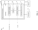
- the controller 60 comprises one or more processors 62 and at least one tangible, non-transitory machine readable medium encoded with one or more programs configured to perform steps for controlling a discharging process of the system having the plurality of battery packs.
- the controller 60, the processor 62, and/or the program 74 may be an external device to the converter 10, or be an internal device inside the converter 10.
- the processor(s) 62 may include a central control 64, which includes a parameter input module 66, model module 68, a parameter control module 70, and information and instruction module 72.
- the parameter input module 66 coordinates with the battery packs 20, optionally BPMU 30 and HMI or EMS 110, to read the data from battery packs 20 and power demand from HMI or EMS 110.
- the parameter input module 66 also coordinates with each power converter 10.
- the parameter control module 70 coordinates with each power converter 10 and each battery pack 20, and optionally with BPMU 30 and HMI or EMS 110 to control a process of discharging.
- the model module 68 is configured to perform a simulation based on the input parameters to provide information and instruction to the parameter control module 70 and the information and instruction module 72.
- the processors 62 may be optionally connected with one or more displays 76 for displaying the information and instructions from module 72 and to an operator.
- the controller 60 with the programs 74 and the processor 62 are configured to perform steps for discharging or charging as described herein. As described in FIG. 4 , in some embodiments, the controller 60 is configured to perform the steps described herein. These steps include: receiving a total power demand (D) needed to be dispatched from the system 100 or to be charged to the system 100, and collecting characteristic data of each battery pack 20.
- the total power demand (D) is the total energy required in a unit time.
- the characteristic data of each battery pack 20 include at least a maximum voltage (V i max ) and a minimum voltage for discharge (V i min ), which can be derived from a curve (e.g., FIG. 3 ) of voltage versus charge of each battery pack 20.
- the characteristic data may also include a maximum total rated power (di max, in Kilowatts) and a present voltage (Vi).
- the characteristic data may also include capacity, state of health (SOH), and/or state of charge (SOC) and other parameters of each battery pack.
- the steps further include determining a voltage distribution parameter (V i* ) of each battery pack based on V i max , V i min , and V i .
- the steps also include ranking the plurality of battery packs 20 by assigning a rank to each battery pack 20 as an order for discharging or charging based on the voltage distribution parameter (V i* ) for each battery pack 20, and determining a respective power discharge or charge for each battery pack based on the rank of each battery pack and the total power demand (D).
- the number of battery packs is represent as "n”.
- the subscript "i" represents battery packs from 1 to n.
- the controller 60 is configured to rank the plurality of battery packs 20 in an increasing order, a decreasing order, or a random order of the voltage distribution parameter (V i* ) of each battery pack.
- the ranks are assigned as from “1” to "n", where n is the number of the total battery packs.
- Rank of "1”, which is the highest rank, has the highest priority for discharging or charging. The power is discharged or charged in the increasing order, the decreasing order, or the random order of the voltage distribution parameter (V i* ), respectively.
- the controller 60 is configured to determine the respective power discharge or charge for each battery 20 by assigning the respective power discharge or charge based on a respective maximum total rated power (d i max ) of each battery pack in the order for discharging or charging until the total power demand (D) is reached. After the total power demand is satisfied, other battery packs with lower ranks may not be assigned for discharging or charging, and the respective power discharge or charge is zero. When the respective power discharge or charge of a certain battery pack is zero, the specific battery pack is kept idle without discharging or charging. Sometimes a battery pack cannot be used to discharge because its voltage is the same as or below its minimum voltage for discharging (i.e., having a voltage collapse), the specific battery pack 20 is kept idle without discharging. Such a battery pack 20 may need to be charged first or replaced.
- the controller 60 is configured to provide the signal with instructions for a pre-determined time interval, and re-determine the respective power discharge or charge for each battery pack 20 after the time interval ends or when a voltage collapse occurs to a battery pack, by repeating the steps described above.
- the controller 60 may be configured to dynamically control discharging or charging of the plurality of battery packs 20 by updating the respective power discharge or charge of each battery pack instantaneously with time.
- the present disclosure provides a controller 60 as described herein for controlling discharge of a system 100 comprising a plurality of battery packs 20.
- the controller 60 is configured to control discharge or charge of heterogeneous battery packs 20, for example, in an electrical energy storage system.
- the controller 60 is configured to discharge power from the plurality of battery packs 20 to a grid or load 85 or charge power to the plurality of battery packs 20.
- the present disclosure also provides a method 200 for controlling discharge or charge of a system 100 comprising a plurality of battery packs 20 through a controller 60 therein as described herein.
- the controller 60 and the method 200 in the present disclosure biases the discharge to battery packs with lower or higher voltage distribution parameter (V*).
- the input parameter may include voltage, current and time.
- Charge or charge flow (Q) is calculated from the current flow and the time elapsed.
- the voltage has a unit of volt (v), and the charge flow has a unit of Amp* hour (Ah) or coulomb.
- Vmax is the voltage of such a battery pack when it is fully charged or it is at its maximum allowable charge level.
- Vmin is the voltage of such a battery pack when it is depleted of charge or it reaches its minimum allowable charge level.
- the curve of voltage versus charge can be empirically generated at constant level of discharge while monitoring the current flow over the discharge period until the voltage drops beyond a user-defined minimum limit (Vmin), shown by the vertical dotted line in FIG. 3 .
- Vmin user-defined minimum limit
- the current and the voltage follow the same or similar trend with increase in charging time.
- the curves of voltage versus charge are empirically generated at constant level of discharge while monitoring the current flow over the discharge period until the voltage drops beyond a user-defined minimum limit, shown by the intersection of the dotted vertical line with horizontal line from the y-axis.
- Different discharge rates may yield different voltage discharge curves for the same battery packs.
- a family of curves at different discharge rates can be provided for each respective battery pack 20, and can be used to track the voltage trajectory of the packs for a given dispatch episode.
- a technique such as extrapolation, interpolation, or averaging is used to get a representative curve.
- Vmax and Vmin are open circuit voltage specified by manufacturer or derived from pre -determined voltage-charge curves. The range of from Vmin to Vmax may be in a range of from 400 volts to 1,000 volts.
- a voltage distribution parameter V* of a battery pack 20 having a present voltage (V) is defined as (V-Vmin)/(Vmax-Vmin).
- V-Vmin present voltage
- Vmax-Vmin voltage
- exemplary battery packs used have V* in a range of from 50% to 95% in some embodiments.
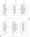
- FIG. 4 illustrates an exemplary method 200 for controlling or managing discharge or charge of a plurality of battery packs 20 in a system 100 in accordance with some embodiments.
- the plurality of battery packs 20 are heterogeneous battery packs selected from new batteries, second-use electric vehicle (EV) batteries, or combinations thereof.
- the plurality of battery packs 20 are connected in parallel, in series, or in a combination thereof.
- the plurality of battery packs 20 are connected preferably in parallel.
- a total power demand needed to be dispatched from or to be charged to the system 100 is received by the controller 60.
- a total power demand may be received from EMS 110.
- characteristic data of each battery pack 20 are collected.
- a curve of voltage versus charge for each battery pack 20 may be established. The voltage and charge in this curve may be referred as the first set or initial values.
- An exemplary curve is shown in FIG. 3 as described above.
- the voltage versus charge (Amp-hr) characteristics of each battery pack may be empirically obtained or derived for a set of frequently encountered discharge rate s. This provides a family of curves that can be used to track the voltage trajectory of the packs for a given dispatch episode.
- the characteristic data of each battery pack includes a maximum voltage (Vi max ), a minimum voltage for discharge (Vi min ), and a present voltage (V i ).
- the data may include a maximum total rated power (d i max ), SOH, and SOC of each battery pack 20.
- the minimum and maximum voltage of each battery pack can be calculated according to the number of the cells in the respective pack and the configuration, in which the cells are arranged. For example, if maximum and minimum voltages of each cell are 4.2V and 3.5V, respectively, and a battery pack includes 144 cells, Vmax for the pack is 4.2 ⁇ 144 V and Vmin for such a battery pack is 3.5 ⁇ 144 V.
- a voltage distribution parameter (V i* ) of each battery pack is determined based on respective V i max , V i min , and V i .
- the plurality of battery packs 20 are ranked by assigning a respective rank to each battery pack as an order for discharging or charging based on the voltage distribution parameter (V i *) for each battery pack.
- a respective power discharge or charge for each battery pack is determined based on the rank of each battery pack and the total power demand (D).
- the ranks for priority or order of discharge or charge are assigned as from 1, 2, 3, to n, which is the number of the battery packs 20 in the system.
- the rank for "1", which is considered as the highest rank, means that the corresponding battery packs are used to satisfy the total power demand (D) first.
- the plurality of battery packs 20 are ranked in an increasing order of the voltage distribution parameter (V i *) of each battery pack.
- the battery pack having the lowest V* is assigned to be "1".
- the plurality of battery packs 20 are ranked in a decreasing order of the voltage distribution parameter (V i *) of each battery pack 20.
- the battery pack having the highest V* is assigned to be "1".
- the plurality of battery packs 20 are ranked in a random order of the voltage distribution parameter (V i *) of each battery pack 20.
- the respective power discharge or charge for each battery is determined by assigning the respective power discharge or charge based on its capacity, for example, a respective maximum total rated power (d i max ) and/or state of charge, of each battery pack in the order for discharging or charging (from rank 1) until the total power demand (D) is reached.
- the respective power discharge or charge for other battery packs might be zero if the total power demand is satisfied by some, but not all, of the battery packs. A certain battery pack is kept idle when the respective power discharge or charge is assigned to zero.
- the capacity of all the battery packs E (in kWh) and the design charge power of the system Pd (in kW) are known.
- a maximum total rated power (d; max , in kW) can be calculated by dividing the capacity of an individual batter pack by the duration. Such calculations can be also performed for discharging or charging.
- steps 210 and 212 For the purpose of illustration only, three embodiments are described below for steps 210 and 212.
- the plurality of battery packs 20 are ranked in an increasing order of the voltage distribution parameter (V i* ) of each battery pack.
- the battery pack having the lowest V* is assigned to be "1" (i.e. the highest priority for discharging or charging), while the battery pack having the highest V* is assigned to be “n” (the total number of the battery packs).
- the power demand (D) or called the total dispatch power (Dd) needed as required by the EMS is provided to the system in a time interval, for example, in 15-minute increments.
- the maximum total rated power is represented in "ddimax".
- the letters "d” and “c” are used to represent “discharge” and “charge”, respectively.
- the power discharge may have an absolute value higher than zero in a unit such as kWh, but power discharge is represented in negative values while the power charge is represented in positive values.
- a respective power charge (dci) is determined according to first selecting packs where Vi ⁇ Vimax and then rank according to V* with rank "1" assigned to the battery pack having lowest V* as described above.
- the method in the first embodiment provides advantages additional to those described herein.
- the battery packs having lower V* which are weaker packs, can be used and exhausted first to extend the life of the stronger packs. After repeated uses, these weak packs may not be workable, and are replaced. A more healthy system can be established.
- the plurality of battery packs 20 are ranked in a decreasing order of the voltage distribution parameter (V i* ) of each battery pack.
- the battery pack having the highest V* is assigned to be "1" while the battery pack having the lowest V* is assigned to be “n”.
- the power demand (D) or called the total dispatch power (Dd) needed as required by the EMS is provided to the system in a time interval, for example, in 15-minute increments.
- the maximum total rated power is represented in "ddimax".
- a respective power charge (dci) is determined according to first selecting packs where Vi ⁇ Vimax and then rank according to V* with rank "1" assigned to the battery pack having highest V* as described above.
- the method in the second embodiment provides advantages additional to those described herein.
- the battery packs having highest V* which are stronger packs, can be used first to extend the life of the weaker packs and the whole system, especially when the replacement of weaker battery packs may not be available.
- the plurality of battery packs 20 are ranked in a random order of the voltage distribution parameter (V i* ) of each battery pack.
- a random program can be used to randomly choose a value of V* from the dataset and select a corresponding battery pack.
- all the battery packs are randomly assigned a rank from "1" to "n”.
- the power demand (D) or called the total dispatch power (Dd) needed as required by the EMS is provided to the system in a time interval, for example, in 15-minute increments.
- the maximum total rated power is represented in "ddimax".
- the battery packs may be randomly ranked again.
- a respective power charge (dci) is determined according to first selecting packs where Vi ⁇ Vimax and then rank according to V* with rank "1" assigned to the battery pack.
- the method in the third embodiment provides advantages additional to those described herein.
- the battery packs having different V* are randomly used.
- the randomization in ranking ensures that the battery packs are uniformly used over a period of time even though a subset of packs are used at a particular moment to satisfy the dispatch requirement from the EMS.
- Such a method extends the life of all the packs and the whole system. This approach is useful when the battery packs in a system are relatively good and uniform.
- the methods provided in the present disclosure utilize a series of heterogeneous battery packs to provide a consistent and long-lasting dispatch profile according to a ranking process based on V* to satisfy the dispatch requirement for discharging or charging from the EMS.
- the managed throughput leads to improved life and performance for an energy storage system.
- signals with instructions are provided from the controller 60 to the plurality of battery packs 20 and the one or more power converters 10 for discharging power from, or charging power to, the plurality of battery packs 20 based on the respective power discharge or charge of each battery pack.
- a certain battery pack is kept idle if the respective power is zero.
- Discharge energy is assumed to be delivered in unit time. Therefore, energy is synonymous with power for dispatch purposes.
- the method 200 further comprises a re-assigning (or re-determining) step or cycle 220.
- the controller 60 provides the signal with instructions for a pre-determined time interval.
- the interval can be defined by a user.
- the time interval may be any time length from 10 second to 2 hours, for example, 1 minute, 2 minutes, 5 minutes, 10 minutes, 15 minutes, 30 minutes, or one hour.
- the controller re-assigns power discharge or charge for the plurality of battery packs after the time interval ends or when a voltage collapse occurs to a battery pack, by repeating some or all of the steps including steps 202, 204, 206, 210, 212, and 214.
- the reassignment process goes back to and starts from step 202. In some embodiments, the reassignment process goes back to and starts from step 204.
- the discharging process of the plurality of battery packs can also be dynamically controlled by updating the respective power discharge or charge of each battery pack instantaneously with time. The time interval can be very short or minimal.
- the system 100 includes a heterogeneous battery packs 20 integrated with bidirectional converter (or inverter) 10 connected to the grid or microgrid 85 that can be dispatched remotely or locally using this intelligent algorithm running in local or cloud-based controller 60.
- the algorithm requires prior knowledge of the voltage-charge curves, which can be acquired during commissioning and subsequently updated as the battery packs age or wear out due to use/disuse.
- the system, the controller, and the method provided in the present disclosure offer many advantages. For example, a variety of battery packs such as used EV battery packs having different quality can be used. No pre-selection or dismantle of the battery packs are needed. The system, the controller, and the method extend the life of some or all battery packs, and they also offer flexibility in maintaining and upgrading the system as well.
- FIGS. 5-9 illustrate the data from the comparative examples while FIGS. 10-14 illustrate the data from the experimental examples following the method of the first embodiment as described above.
- the battery packs can discharge maximum at 0.5 C and charged at 0.5 C.
- the C rating of 0.5 C means that the battery usable capacity of a battery pack is used (charged or discharged) in two hours. There capacities and voltage characteristics are different, so their recommended/allowable maximum charge and discharge rates are different. It is assumed that maximum total rated power for battery packs 1, 2, 3, and 4 is 3.16 kW, 6.66 kW, 6.95 kW, 7.71 kW, respectively. The maximum total power is based on the C rating. For example, if the C rating is 0.5 C according to the specification, a 10 kWh battery has a maximum power of 5 kW. The actual power charged or discharged from a battery pack is different from its maximum power, and is determined according to the method described herein.
- V* voltage distribution parameter
- the order of V* for battery packs is in an increasing order from Pack 1, Pack 2, Pack 3, to Pack 4 (with the highest V*).
- the capacity (Dimax) for Pack 1, Pack 2, Pack 3, to Pack 4 is 6.32, 13.32, 13.90, and 15.42 kWh, respectively.
- the total power demand (D) is negative for discharging and positive for charging, and is divided among the four packs by the controller 60. In the comparative example, the total power demand is equally divided among the four battery packs.
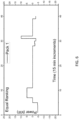
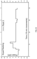
- Table 2 and FIGS. 6-9 illustrate the respective power discharge from each battery pack (Packs 1, 2, 3, and 4, respectively) to meet the total power demand as shown in Table 1 and FIG. 5 .
- TABLE 2 Respective power discharge or charge for each battery pack in the comparative example Interval (15 minutes) Pack 1 Pack 2 Pack 3 Pack 4 1 -4.39 -4.39 -4.39 -4.39 -4.39 2 -4.47 -4.47 -4.47 3 -4.47 -4.47 -4.47 -4.47 -4.47 4.47 4.47 -4.47 -4.47 -4.47 5 -4.31 -4.31 -4.31 -4.31 6 0.00 -5.85 -5.85 -5.85 7 0.00 0.00 0.00 0.00 0.00 0.00 0.00 0.00 0.00 0.00 0.00 0.00 0.00 0.00 5.00 5.00 9 5.00 5.00 5.00 10 5.00 5.00 11 0.00 0.00 0.00 0.00 0.00 0.00 0.00 0.00 0.00 5.00 5.00 5.00 11
- the four battery packs are individually dispatched at equal power in general. In scenarios where one or more pack(s) have reached their SOC of 0 or 100%, they rebalance to adjust power between each other. At every moment the power dispatched from all packs are equal, except the ones that have reached a zero power status. For example, in each of the 12th and 32th intervals, two battery packs have SOC or capacity reaching zero.
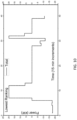
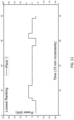
- FIG. 10 illustrates the total power demand or dispatch needed from an exemplary system including four battery packs (Packs 1, 2, 3, and 4) at different time intervals (each with 15 minutes) for the experimental example.
- the battery packs are ranked in an increasing order of the voltage distribution parameter (V*) as the order of discharge and a battery pack having the lowest V* discharges first.
- V* voltage distribution parameter
- the voltage of each pack is also in the same order from the lowest to the highest V as the maximum power from each pack from the lowest to the highest.
- the order of the voltage from the lowest to highest remains the same after every 15 minute increment when a new rank order is established.
- Table 3 and FIGS. 11-14 illustrate the respective power discharge from each battery pack (Packs 1, 2, 3, and 4, respectively) to meet the total power demand as shown in FIG. 10 .
- TABLE 3 Respective power discharge or charge for each battery packs in the Experimental Example Interval (15 minutes) Pack 1 Pack 2 Pack 3 Pack 4 1 -3.16 -6.66 -6.95 -0.79 2 -3.16 -6.66 -6.95 -1.11 3 -3.16 -6.66 -6.95 -1.11 4 -3.16 -6.66 -6.95 -1.11 5 -3.16 -6.66 -6.95 -0.47 6 -3.16 -6.66 -6.95 -0.76 7 0.00 0.00 0.00 0.00 0.00 8 3.16 6.66 6.95 0.00 9 3.16 6.66 6.95 0.00 10 3.16 6.66 6.95 0.00 11 3.16 6.66 6.95 0.00 12 3.16 6.66 6.95 0.00 13 0.00 0.00 0.00 0.00 14 0.00 0.00 0.00 0.00 0.00 15 0.00
- the battery packs are individually dispatched at different powers. In scenarios where one or more pack(s) have reached their SOC of 0 or 100%, they rebalance to adjust powers among the packs.
- FIGS. 6-9 and FIGS. 11-14 are most evident when FIG. 9 and FIG. 14 are compared.
- Battery pack 4 is the strongest pack. As shown in FIG. 5 , Pack 4 is used significantly for equal ranking. But as shown in FIG. 14 , Pack 4 is used less frequently. So its life is extended. The weak packs are used more frequently and will be replaced when it is not workable.
- the two sets of figures and tables show that the power profiles for the battery packs are significantly different between the experimental sample and the comparative sample. This rank order results in more usage of "lower quality" packs more often, so they will be replaced. This will lead to a more uniform spectrum of battery packs as the energy storage system ages.
- the methods and system described herein may be at least partially embodied in the form of computer-implemented processes and apparatus for practicing those processes.
- the disclosed methods may also be at least partially embodied in the form of tangible, non-transient machine readable storage media encoded with computer program code.
- the media may include, for example, RAMs, ROMs, CD-ROMs, DVD-ROMs, BD-ROMs, hard disk drives, flash memories, or any other non-transient machine-readable storage medium, or any combination of these mediums, wherein, when the computer program code is loaded into and executed by a computer, the computer becomes an apparatus for practicing the method.
- the methods may also be at least partially embodied in the form of a computer into which computer program code is loaded and/or executed, such that, the computer becomes an apparatus for practicing the methods.
- the computer program code segments configure the processor to create specific logic circuits.
- the methods may alternatively be at least partially embodied in a digital signal processor formed of application specific integrated circuits for performing the methods.
- the computer or the control unit may be operated remotely using a cloud based system.
Landscapes
- Engineering & Computer Science (AREA)
- Power Engineering (AREA)
- Manufacturing & Machinery (AREA)
- Chemical & Material Sciences (AREA)
- Chemical Kinetics & Catalysis (AREA)
- Electrochemistry (AREA)
- General Chemical & Material Sciences (AREA)
- Microelectronics & Electronic Packaging (AREA)
- Charge And Discharge Circuits For Batteries Or The Like (AREA)
Abstract
Description
- This application claims benefit of
US Application No. 17/506,137 filed October 20, 2021 - The disclosure relates to systems and methods for controlling or managing battery packs generally. More particularly, the disclosed subject matter relates to a controller, a system, and a method for managing discharge or charge of battery packs, for example, in energy storage application.
- Clean and renewable sources of energy become more important due to increased concerns about environmental issues such as global warming. Such sources include solar and wind power, and rechargeable battery. Renewable energy sources are intermittent because they cannot always be dispatched when needed to meet the changing requirements of energy consumers. Energy storage systems are expected to solve this flexibility challenge. A stationary energy storage system can store energy and release energy in the form of electricity when it is needed.
- The present disclosure provides a controller for controlling or managing discharge or charge of heterogeneous battery packs, a system such as an electrical energy storage system comprising such a controller, and methods of using the same.
- In accordance with some embodiments, the controller, the system, and the method utilize a technique of ranking a plurality of battery packs based on a voltage distribution parameter of each battery pack. The ranking order of the plurality of battery packs is used as an order for discharging power from the system or charging power to the system.
- In accordance with some embodiments, a system comprises a plurality of battery packs, one or more power converters, and one or more controller. Each power converter is coupled with at least one of the plurality of battery packs, and is configured to convert direct current (DC) from one battery pack to alternating current (AC) or vice versa. The controller is coupled to the plurality of battery packs and the one or more power converters. In some embodiments, the system may also include more than one controller, and each controller is coupled to a plurality of battery packs.
- The plurality of battery packs are defined and described herein. In some embodiments, the plurality packs are heterogeneous battery packs, which can be selected from new batteries, second-use electric vehicle (EV) batteries, or combinations thereof. The plurality of battery packs are connected in parallel, in series, or in a combination (i.e. hybrid combinations) thereof. In some embodiments, the plurality of battery packs are connected in parallel.
- The controller comprises one or more processors and at least one tangible, non-transitory machine readable medium encoded with one or more programs configured to perform steps for controlling or managing a discharging process or a charging process of the system having the plurality of battery packs. In some embodiments, these steps include: receiving a total power demand (D) (or called total dispatch power) needed to be dispatched from the system or to be charged to the system, and collecting characteristic data of each battery pack. The characteristic data of each battery pack include a maximum voltage (Vi max), a minimum voltage for discharge (Vi min), and a present voltage (Vi). The characteristic data may also include a maximum total rated power (di max) of each battery, state of health (SOH), and/or state of charge (SOC).
- The steps further include determining a voltage distribution parameter (Vi*) of each battery pack based on Vi max, Vi min, and Vi. The steps also include ranking the plurality of battery packs by assigning a rank to each battery pack as an order for discharging or charging based on the voltage distribution parameter (Vi*) for each battery pack, and determining a respective power discharge or charge for each battery pack based on the rank of each battery pack and the total power demand (D).
- The steps also further include providing signals with instructions to the plurality of battery packs and the one or more power converters for discharging power from or charging power to the plurality of battery packs based on the respective discharge power of each battery pack and/or keeping a certain battery pack idle.
- In some embodiments, the controller is configured to rank the plurality of battery packs in an increasing order, a decreasing order, or a random order of the voltage distribution parameter (V i*) of each battery pack. The power is discharged or charged in the increasing order, the decreasing order, or the random order of the voltage distribution parameter (Vi*), respectively. The controller is configured to determine the respective power discharge or charge for each battery by assigning the respective power discharge or charge based on a respective maximum total rated power (di max) of each battery pack in the order for discharging or charging until the total power demand (D) is reached. After the total power demand is satisfied, other battery packs with lower ranks may not be assigned for discharging or charging, and the respective power discharge or charge is zero. When the respective power discharge or charge of a certain battery pack is zero, the specific battery pack is kept idle without discharging or charging.
- In some embodiments, the controller is configured to provide the signal with instructions for a pre-determined time interval, and re-determine the respective power discharge or charge for each battery pack after the time interval ends or when a voltage collapse occurs to a battery pack, by repeating the steps described above. The controller may be configured to dynamically control discharging or charging of the plurality of battery packs by updating the respective power discharge or charge of each battery pack instantaneously with time.
- The system may optionally further comprise one or more battery power management unit (BPMU). Each BPMU may be connected with one or more battery packs, and is configured to monitor the one or more battery packs and provide characteristic data of the one or more battery packs to the controller.
- In some embodiments, the system is an electrical energy storage system. The total power demand is provided from an upper level energy management system (EMS). In some embodiments, the controller is configured to discharge power from the plurality of battery packs to a grid or load or charge power from the grid or load to the plurality of battery packs. In some embodiments, the grid is optional. The power can be discharged to other components, in which electrical power is needed.
- In another aspect, the present disclosure provides a controller as described herein for controlling or managing discharge or charge of a system comprising a plurality of battery packs. As described herein, such a controller comprises one or more processor and at least one tangible, non-transitory machine readable medium encoded with one or more programs configured to perform the steps as described herein.
- The controller is configured to provide signals with instructions to the plurality of battery packs and the one or more power converters for discharging power from (or charging power to) the plurality of battery packs based on the respective discharge power of each battery pack and/or keeping a certain battery pack idle.
- The plurality of battery packs, which the controller is configured to be coupled with, are heterogeneous battery packs selected from new batteries, second-use electric vehicle (EV) batteries, or combinations thereof. The plurality of battery packs are connected in parallel, in series, or in a combination thereof. The controller is configured to rank the plurality of battery packs in an increasing order, a decreasing order, or a random order of the voltage distribution parameter (Vi*) of each battery pack. The power is discharged or charged in the increasing order, the decreasing order, or the random order of the voltage distribution parameter (Vi*), respectively.
- The controller is configured to provide the signal with instructions for a pre-determined time interval, and re-determine the respective power discharge or charge for each battery pack after the time interval ends or when a voltage collapse occurs to a battery pack, by repeating steps. The controller is also configured to dynamically control discharging or charging of the plurality of battery packs by updating the respective power discharge or charge for each battery pack instantaneously with time.
- The controller is configured for controlling discharge or charge of heterogeneous battery packs, for example, in an electrical energy storage system. In some embodiments, the controller is configured to discharge power from the plurality of battery packs to a grid or load, or charge power from the grid or load to the plurality of battery packs.
- In another aspect, the present disclosure provides a method for controlling or managing discharge or charge of a system comprising a plurality of battery packs through a controller therein as described herein. The method includes steps of: receiving a total power demand (D) needed to be dispatched from the system or to be charged to the system, and collecting characteristic data of each battery pack. The characteristic data of each battery pack include a maximum voltage (Vi max), a minimum voltage for discharge (Vi min), and a present voltage (Vi). Other data may include SOH, SOC, and a maximum total rated power (di max) of each battery pack.
- The method further includes determining a voltage distribution parameter (Vi*) of each battery pack based on Vi max, Vi min, and Vi, ranking the plurality of battery packs by assigning a rank to each battery pack as an order for discharging or charging based on the voltage distribution parameter (Vi*) for each battery pack, and determining a respective power discharge or charge for each battery pack based on the rank of each battery pack and the total power demand (D).
- In such a method, the controller also provides signals with instructions to the plurality of battery packs and the one or more power converters for discharging power from or charging power to the plurality of battery packs based on the respective power discharge or charge of each battery pack and/or keeping a certain battery pack idle as described herein. In some embodiments, instructions are sent from the controller to each battery pack and/or one or more converter connected with the plurality of battery packs for discharging or charging based on the respective power discharge or charge of each battery pack.
- The plurality of battery packs are heterogeneous battery packs selected from new batteries, second-use electric vehicle (EV) batteries, or combinations thereof. The plurality of battery packs are connected in parallel, in series, or in a combination thereof.
- In accordance with some embodiments, the voltage distribution parameter (Vi*) of each battery pack is determined using Equation (1):

- In some embodiments, the plurality of battery packs are ranked in an increasing order of the voltage distribution parameter (Vi*) of each battery pack. In some other embodiments, the plurality of battery packs are ranked in a decreasing order of the voltage distribution parameter (Vi*) of each battery pack. Alternatively, the plurality of battery packs are ranked in a random order of the voltage distribution parameter (Vi*) of each battery pack. In each scenario, the respective power discharge or charge for each battery is determined by assigning the respective power discharge or charge based on a respective maximum total rated power (di max) of each battery pack in the order for discharging or charging until the total power demand (D) is reached. The respective power discharge or charge for other battery packs is zero. A certain battery pack is kept idle when the respective power discharge or charge is assigned to zero.
- In some embodiments, some or all the steps above are repeated to re-determine the respective power discharge or charge of each battery pack after a pre-determined time interval ends or when a voltage collapse occurs to a battery pack. The discharging process of the plurality of battery packs can also be dynamically controlled by updating the respective power discharge or charge of each battery pack instantaneously with time.
- The system, the controller, and the method provided in the present disclosure offer many advantages. For example, a variety of new and used battery packs having different quality can be used. No pre-selection or dismantle of the battery packs are needed. The plurality of heterogeneous battery packs collectively supply power load to satisfy the power demand while each battery pack may discharge at a different share. As described herein, the system, the controller, and the method selectively extend the life of battery packs having higher or lower V* or the life of all battery packs, and they also offer flexibility in maintaining and upgrading the system as well.
- The present disclosure is best understood from the following detailed description when read in conjunction with the accompanying drawings. It is emphasized that, according to common practice, the various features of the drawings are not necessarily to scale. On the contrary, the dimensions of the various features are arbitrarily expanded or reduced for clarity. Like reference numerals denote like features throughout specification and drawings.
-
FIG. 1 is a block diagram illustrating an exemplary system comprising heterogeneous battery packs and a controller in accordance with some embodiments. -
FIG. 2 is a block diagram illustrating an exemplary controller comprising one or more processor and at least one tangible, non-transitory machine readable medium encoded with one or more programs, for controlling or managing discharge or charge of a plurality of heterogeneous battery packs in accordance with some embodiments. -
FIG. 3 shows the relationship between voltage (V) and charge flow (Ah) of an exemplary battery pack in some embodiments. -
FIG. 4 is a flow chart illustrating an exemplary method for controlling discharge or charge of battery packs in accordance with some embodiments. -
FIG. 5 illustrates the total power demand or dispatch needed from an exemplary system including four battery packs (Packs -
FIGS. 6-9 illustrate the respective power discharge from each battery pack (Packs FIG. 5 . -
FIG. 10 illustrates the total power demand or dispatch needed from an exemplary system including four battery packs (Packs -
FIGS. 11-14 illustrate the respective power discharge from each battery pack (Packs FIG. 10 . - This description of the exemplary embodiments is intended to be read in connection with the accompanying drawings, which are to be considered part of the entire written description. In the description, relative terms such as "lower", "upper", "horizontal", "vertical", "above", "below", "up", "down", "top" and "bottom" as well as derivative thereof (e.g., "horizontally", "downwardly", "upwardly", etc.) should be construed to refer to the orientation as then described or as shown in the drawing under discussion. These relative terms are for convenience of description and do not require that the apparatus be constructed or operated in a particular orientation. Terms concerning attachments, coupling and the like, such as "connected" and "interconnected", refer to a relationship wherein structures are secured or attached to one another either directly or indirectly through intervening structures, as well as both movable or rigid attachments or relationships, unless expressly described otherwise.
- For purposes of the description hereinafter, it is to be understood that the embodiments described below may assume alternative variations and embodiments. It is also to be understood that the specific articles, compositions, and/or processes described herein are exemplary and should not be considered as limiting.
- In the present disclosure the singular forms "a", "an", and "the" include the plural reference, and reference to a particular numerical value includes at least that particular value, unless the context clearly indicates otherwise. When values are expressed as approximations, by use of the antecedent "about", it will be understood that the particular value forms another embodiment. As used herein, "about X" (where X is a numerical value) preferably refers to ±10% of the recited value, inclusive. For example, the phrase "about 8" preferably refers to a value of 7.2 to 8.8, inclusive. Where present, all ranges are inclusive and combinable. For example, when a range of "1 to 5" is recited, the recited range should be construed as including ranges "1 to 4", "1 to 3", "1-2", "1-2 & 4-5", "1-3 & 5", "2-5", and the like. In addition, when a list of alternatives is positively provided, such listing can be interpreted to mean that any of the alternatives may be excluded, e.g., by a negative limitation in the claims. For example, when a range of "1 to 5" is recited, the recited range may be construed as including situations whereby any of 1, 2, 3, 4, or 5 are negatively excluded; thus, a recitation of "1 to 5" may be construed as "1 and 3-5, but not 2", or simply "wherein 2 is not included". It is intended that any component, element, attribute, or step that is positively recited herein may be explicitly excluded in the claims, whether such components, elements, attributes, or steps are listed as alternatives or whether they are recited in isolation.
- References to "heterogeneous battery packs" made herein refer to battery packs or modules having different capacity, state of charge (SOC), state of heath (SOH), and/or voltages, and can be selected from new batteries (e.g., from different manufacturers), second-use electric vehicle (EV) batteries, or combinations thereof. Second-use EV batteries are used for illustration purpose. References to "discharging" from or "charging" to the plurality of battery packs are understood that the plurality of batteries packs collectively discharge or be charged, while it is possible that some battery packs may stay idle (without charging or discharging).
- Unless expressly indicated otherwise, references to "state of health (SOH)" made herein will be understood to mean a figure of merit of the condition of a battery, a battery cell, or a battery pack compared to its ideal conditions. SOH is characterized in percentage (%). The condition matching the specifications under the ideal conditions is 100%. SOH may decrease over time and use.
- Unless expressly indicated otherwise, "state of charge" (SOC) described herein is defined as a level of charge of an electric battery relative to its capacity. The units of SOC are percentage points, 0% means empty, and 100% means full.
- The term "human machine interface (HMI)" used herein is understood to refer to user interface (UI) is the space where interactions between humans and machines occur. A human-machine interface (HMI) may involve interfaces between human and machines with physical input hardware such as keyboards, mice, or any other human interaction based on tactile, visual, or auditory senses. Such user interfaces may include other layers such as output hardware such as computer monitors, speakers, and printers.
- The term "energy management system (EMS)" used herein refers to a system of computer-aided tools used by operators of electric utility grids to monitor, control, and optimize the performance of the generation or transmission system.
- In the present disclosure, the terms "power demand", "power dispatch", and "power requirement" are used interchangeably, and can be referred to the power needed for either a discharging or a charging process. The terms "converter" and "inverter" can be used interchangeably. Each battery pack includes an inverter and a battery management unit (BMU) therein. For the convenience of description, the term "power inverter" or "AC/DC power converter" is used to describe the internal component in a battery pack, and the term "power converter" or "power conversion system (PCS)" is used to describe the converter connected with one or more battery packs. The term of "battery management unit (BMU)" or "battery management system (BMS)" is used to describe the internal component in a battery pack, and the term "battery power management unit (BPMU)" is used to describe the battery management unit connected with one or more battery packs.
- In the present disclosure, the terms "power" and "energy" are used interchangeably, and the energy are described in a unit of time. Energy and power can be converted with time.
- Unless expressly indicated otherwise, the term "connected" or "coupled" used herein are understood to encompass different connections or coupling between or among the components so as to conduct electricity or transmit signals for communication. Such a connection or coupling can be through wire, wireless, or cloud-based modes.
- Power dispatch (discharge) is a function of charge flow and voltage. Dispatch energy is defined as dispatch power over a user-specified period of time. Higher voltage discharge provides higher power compared to low voltage discharge for the same amount of charge flow. Earlier approaches have not considered the impact of voltage on the decision of power or energy dispatch. Moreover, heterogeneity in the voltages of battery packs and voltage trajectory during discharge have not been considered.
- Heterogeneous battery packs can be pre-sorted before use. For example, batteries or battery packs with similar performance can be sorted in groups to make new battery packs or systems. The state of charge (SOC) can be used as a criterion to sort out the batteries or battery packs. However, this sorting done prior to use is not on a dynamic basis. A more efficient method for using the heterogeneous battery packs is needed.
- The present disclosure provides a controller for controlling discharge or charge of heterogeneous battery packs, a system such as an electrical energy storage system comprising such a controller, and methods of using the same. The present disclosure provides such a controller, such a system, and such a method to efficiently utilize heterogeneous batteries such as new batteries from different manufactures or second-use electric vehicle (EV) battery packs in energy storage applications. Every battery pack is operated individually according to its characters such as a voltage distribution parameter. Preselecting or dismantling packs is not required. In accordance with some embodiments, the controller, the system, and the method utilize a technique of ranking a plurality of battery packs based on voltage distribution parameter (V*), other than SOC, of each battery pack. The ranking order of the plurality of battery packs is used as an order for discharging power from the system or charging power to the system. The priority of discharging or charging the discharging for a plurality of battery packs are determined by the voltage distribution parameter as described herein.
- The controller, the system, and the method provided in the present disclosure apply to different battery packs. The battery packs may have the same or different chemistries, same or different performance or degradation, same or different physical and/or electrical performances. In some embodiments, the battery packs are heterogeneous battery packs.
- In
FIGS. 1-2 , like items are indicated by like reference numerals, and for brevity, descriptions of the structure, provided above with reference to the preceding figures, are not repeated. The methods described inFIG. 4 are described with reference to the exemplary structure described inFIGS. 1-2 and the data sketch inFIG. 3 . - Referring to
FIG. 1 , anexemplary system 100 comprises one ormore power converters 10, a plurality of battery packs 20, and acontroller 60. The number of each component and the configuration inFIG. 1 are for illustration only. The system may have any suitable number of each component in any suitable combination or configuration. - Each
power converter 10 is coupled with at least one of the plurality of battery packs 20, and is configured to convert direct current (DC) from a battery pack to alternating current (AC) or vice versa. Thepower converter 10 can be also called as power conversion system (PCS) or an inverter. - The
controller 60 is coupled to the plurality of battery packs 20 and the one ormore power converters 10. In some embodiments, the system may also include more than onecontroller 60, and eachcontroller 60 is coupled to a plurality of battery packs 20. - The
controller 60 may be coupled to the plurality of battery packs 20 directly or indirectly. For example, in some embodiments, theexemplary system 100 may optionally further comprise one or more battery power management unit (BPMU), which can be also called battery management unit (BMU). EachBPMU 30 may be connected with one or more battery packs 20, and is configured to monitor the one or more battery packs 20 and provide characteristic data of the one or more battery packs 20 to thecontroller 60. In some embodiments, thecontroller 60 is configured to read the data from eachbattery pack 20. This may be done through eachrespective BPMU 30 connected with each battery pack. - The plurality of battery packs 20 are heterogeneous battery packs, which can be selected from new batteries, second-use electric vehicle (EV) batteries, or combinations thereof. The plurality of battery packs 20 are connected in parallel, in series, or in a combination thereof. In some embodiments, the plurality of battery packs 20 are connected in parallel. No series connection between battery packs eliminates circulating currents and losses.
- As shown in
FIG. 1 , the plurality of battery packs 20 are connected in a parallel configuration. In some embodiments, the plurality of battery packs 20 are second-use (i.e. used) electric vehicle (EV) batteries. The used EV batteries can be directly utilized in the system, without pre -selection or dismantling. Eachbattery pack 20 comprises a battery or batteries. Each battery packs 20 may include an internal battery management unit (BMU), and an internal inverter. EV battery packs 20 are removed from vehicles and are not disassembled into modules. Simple tests may be done on these EV battery packs 20 to verify their SOH. - In some embodiments, the
exemplary system 100 is an electrical energy storage system. Thecontroller 60 is configured to receive a total power demand provided from an upper level energy management system (EMS) 110. In some embodiments, thecontroller 60 is configured to discharge power from the plurality of battery packs 20 in direct current to a grid orload 85 in alternating current. Theexemplary system 100 can be used for discharging power from battery packs 20 to agrid 85, or for charging from thegrid 85 to battery packs 20.Wire connection 12 may be used. The dottedlines 13 inFIG. 1 illustrates alternative power cables. Multiple power cable topologies may exist between theconverter 10 and battery packs 20. Thesystem 100 directly uses grid tied AC/DC converters 10 with flexibility in size expansion. No additional power conversion system is required for grid tied applications. - In some embodiments, the
grid 85 is optional. The power can be discharged to other components, in which electrical power is needed. - The
controller 60 may be connected with other components in wire or wireless mode. In theexemplary system 100 illustrated inFIG. 1 , thecontroller 60 may be connected with other components such asconverter 10,BPMU 30 andEMS 110 via data cable orwireless connection 22. TheBPMU 30 may be also connected with battery packs 20 via data cables orwireless connection 22. Thecontroller 60 can work in a cloud-based mode. - Each
battery pack 20 may be connected to a power converter 10 (or independent DC port on a converter 10) through a set of automatic DC circuit breakers (not shown), which activate and control the connection between abattery pack 20 and theconverter 10. Theconverter 10 controls whether or not to charge or discharge the singleEV battery pack 20 by following the instructions from thecontroller 60. - Referring to
FIG. 2 , thecontroller 60 comprises one ormore processors 62 and at least one tangible, non-transitory machine readable medium encoded with one or more programs configured to perform steps for controlling a discharging process of the system having the plurality of battery packs. Thecontroller 60, theprocessor 62, and/or theprogram 74 may be an external device to theconverter 10, or be an internal device inside theconverter 10. - The processor(s) 62 may include a
central control 64, which includes aparameter input module 66,model module 68, aparameter control module 70, and information andinstruction module 72. Theparameter input module 66 coordinates with the battery packs 20, optionally BPMU 30 and HMI orEMS 110, to read the data from battery packs 20 and power demand from HMI orEMS 110. Theparameter input module 66 also coordinates with eachpower converter 10. Theparameter control module 70 coordinates with eachpower converter 10 and eachbattery pack 20, and optionally withBPMU 30 and HMI orEMS 110 to control a process of discharging. Together with the one ormore programs 74, themodel module 68 is configured to perform a simulation based on the input parameters to provide information and instruction to theparameter control module 70 and the information andinstruction module 72. Theprocessors 62 may be optionally connected with one ormore displays 76 for displaying the information and instructions frommodule 72 and to an operator. - The
controller 60 with theprograms 74 and theprocessor 62 are configured to perform steps for discharging or charging as described herein. As described inFIG. 4 , in some embodiments, thecontroller 60 is configured to perform the steps described herein. These steps include: receiving a total power demand (D) needed to be dispatched from thesystem 100 or to be charged to thesystem 100, and collecting characteristic data of eachbattery pack 20. The total power demand (D) is the total energy required in a unit time. The characteristic data of eachbattery pack 20 include at least a maximum voltage (Vi max) and a minimum voltage for discharge (Vi min), which can be derived from a curve (e.g.,FIG. 3 ) of voltage versus charge of eachbattery pack 20. The characteristic data may also include a maximum total rated power (di max, in Kilowatts) and a present voltage (Vi). The characteristic data may also include capacity, state of health (SOH), and/or state of charge (SOC) and other parameters of each battery pack. - The steps further include determining a voltage distribution parameter (Vi*) of each battery pack based on Vi max, Vi min, and Vi. The steps also include ranking the plurality of battery packs 20 by assigning a rank to each
battery pack 20 as an order for discharging or charging based on the voltage distribution parameter (Vi*) for eachbattery pack 20, and determining a respective power discharge or charge for each battery pack based on the rank of each battery pack and the total power demand (D). The number of battery packs is represent as "n". The subscript "i" represents battery packs from 1 to n. - In some embodiments, the
controller 60 is configured to rank the plurality of battery packs 20 in an increasing order, a decreasing order, or a random order of the voltage distribution parameter (Vi*) of each battery pack. The ranks are assigned as from "1" to "n", where n is the number of the total battery packs. Rank of "1", which is the highest rank, has the highest priority for discharging or charging. The power is discharged or charged in the increasing order, the decreasing order, or the random order of the voltage distribution parameter (Vi*), respectively. Thecontroller 60 is configured to determine the respective power discharge or charge for eachbattery 20 by assigning the respective power discharge or charge based on a respective maximum total rated power (di max) of each battery pack in the order for discharging or charging until the total power demand (D) is reached. After the total power demand is satisfied, other battery packs with lower ranks may not be assigned for discharging or charging, and the respective power discharge or charge is zero. When the respective power discharge or charge of a certain battery pack is zero, the specific battery pack is kept idle without discharging or charging. Sometimes a battery pack cannot be used to discharge because its voltage is the same as or below its minimum voltage for discharging (i.e., having a voltage collapse), thespecific battery pack 20 is kept idle without discharging. Such abattery pack 20 may need to be charged first or replaced. - In some embodiments, the
controller 60 is configured to provide the signal with instructions for a pre-determined time interval, and re-determine the respective power discharge or charge for eachbattery pack 20 after the time interval ends or when a voltage collapse occurs to a battery pack, by repeating the steps described above. Thecontroller 60 may be configured to dynamically control discharging or charging of the plurality of battery packs 20 by updating the respective power discharge or charge of each battery pack instantaneously with time. - The present disclosure provides a
controller 60 as described herein for controlling discharge of asystem 100 comprising a plurality of battery packs 20. Thecontroller 60 is configured to control discharge or charge of heterogeneous battery packs 20, for example, in an electrical energy storage system. Thecontroller 60 is configured to discharge power from the plurality of battery packs 20 to a grid or load 85 or charge power to the plurality of battery packs 20. - The present disclosure also provides a
method 200 for controlling discharge or charge of asystem 100 comprising a plurality of battery packs 20 through acontroller 60 therein as described herein. - Different battery packs, especially second life or used batteries or batteries that have different capacities and ratings, have varying voltage-charge characteristics. The
controller 60 and themethod 200 in the present disclosure biases the discharge to battery packs with lower or higher voltage distribution parameter (V*). - Referring to
FIG. 3 , an exemplary curve of voltage with charge flow of anexemplary battery pack 20 during a discharging process is shown. The input parameter may include voltage, current and time. Charge or charge flow (Q) is calculated from the current flow and the time elapsed. The voltage has a unit of volt (v), and the charge flow has a unit of Amp* hour (Ah) or coulomb. As shown inFIG. 3 , Vmax is the voltage of such a battery pack when it is fully charged or it is at its maximum allowable charge level. Vmin is the voltage of such a battery pack when it is depleted of charge or it reaches its minimum allowable charge level. - The curve of voltage versus charge can be empirically generated at constant level of discharge while monitoring the current flow over the discharge period until the voltage drops beyond a user-defined minimum limit (Vmin), shown by the vertical dotted line in
FIG. 3 . The current and the voltage follow the same or similar trend with increase in charging time. In some embodiments, the curves of voltage versus charge are empirically generated at constant level of discharge while monitoring the current flow over the discharge period until the voltage drops beyond a user-defined minimum limit, shown by the intersection of the dotted vertical line with horizontal line from the y-axis. - Different discharge rates may yield different voltage discharge curves for the same battery packs. A family of curves at different discharge rates can be provided for each
respective battery pack 20, and can be used to track the voltage trajectory of the packs for a given dispatch episode. In some embodiments, a technique such as extrapolation, interpolation, or averaging is used to get a representative curve. In one curve, when the voltage decreases beyond Vmin during discharge, such a battery pack shows a significantly higher voltage gradient and depletes more quickly. This lower limit point can be also referred as voltage collapse. In some embodiments, Vmax and Vmin are open circuit voltage specified by manufacturer or derived from pre -determined voltage-charge curves. The range of from Vmin to Vmax may be in a range of from 400 volts to 1,000 volts. - A voltage distribution parameter V* of a
battery pack 20 having a present voltage (V) is defined as (V-Vmin)/(Vmax-Vmin). The higher the parameter, the higher degree this battery pack is capable of for further discharge. For example, exemplary battery packs used have V* in a range of from 50% to 95% in some embodiments. -
FIG. 4 illustrates anexemplary method 200 for controlling or managing discharge or charge of a plurality of battery packs 20 in asystem 100 in accordance with some embodiments. The plurality of battery packs 20 are heterogeneous battery packs selected from new batteries, second-use electric vehicle (EV) batteries, or combinations thereof. The plurality of battery packs 20 are connected in parallel, in series, or in a combination thereof. The plurality of battery packs 20 are connected preferably in parallel. - Referring to
FIG. 4 , atstep 202, a total power demand needed to be dispatched from or to be charged to thesystem 100 is received by thecontroller 60. As described herein, a total power demand may be received fromEMS 110. - At
step 204, characteristic data of eachbattery pack 20 are collected. A curve of voltage versus charge for eachbattery pack 20 may be established. The voltage and charge in this curve may be referred as the first set or initial values. An exemplary curve is shown inFIG. 3 as described above. The voltage versus charge (Amp-hr) characteristics of each battery pack may be empirically obtained or derived for a set of frequently encountered discharge rate s. This provides a family of curves that can be used to track the voltage trajectory of the packs for a given dispatch episode. The characteristic data of each battery pack includes a maximum voltage (Vi max), a minimum voltage for discharge (Vi min), and a present voltage (Vi). The data may include a maximum total rated power (di max), SOH, and SOC of eachbattery pack 20. - The minimum and maximum voltage of each battery pack can be calculated according to the number of the cells in the respective pack and the configuration, in which the cells are arranged. For example, if maximum and minimum voltages of each cell are 4.2V and 3.5V, respectively, and a battery pack includes 144 cells, Vmax for the pack is 4.2×144 V and Vmin for such a battery pack is 3.5×144 V.
- At
step 206, a voltage distribution parameter (Vi*) of each battery pack is determined based on respective Vi max, Vi min, and Vi. In some embodiments, V* is determined by using the voltage distribution parameter (Vi*) of each battery pack is determined using Equation (1):
- At
step 210, the plurality of battery packs 20 are ranked by assigning a respective rank to each battery pack as an order for discharging or charging based on the voltage distribution parameter (Vi*) for each battery pack. - At
step 212, a respective power discharge or charge for each battery pack is determined based on the rank of each battery pack and the total power demand (D). The ranks for priority or order of discharge or charge are assigned as from 1, 2, 3, to n, which is the number of the battery packs 20 in the system. The rank for "1", which is considered as the highest rank, means that the corresponding battery packs are used to satisfy the total power demand (D) first. - In some embodiments, the plurality of battery packs 20 are ranked in an increasing order of the voltage distribution parameter (Vi*) of each battery pack. The battery pack having the lowest V* is assigned to be "1". In some other embodiments, the plurality of battery packs 20 are ranked in a decreasing order of the voltage distribution parameter (Vi*) of each
battery pack 20. The battery pack having the highest V* is assigned to be "1". Alternatively, the plurality of battery packs 20 are ranked in a random order of the voltage distribution parameter (Vi*) of eachbattery pack 20. In each scenario, the respective power discharge or charge for each battery is determined by assigning the respective power discharge or charge based on its capacity, for example, a respective maximum total rated power (di max) and/or state of charge, of each battery pack in the order for discharging or charging (from rank 1) until the total power demand (D) is reached. The respective power discharge or charge for other battery packs might be zero if the total power demand is satisfied by some, but not all, of the battery packs. A certain battery pack is kept idle when the respective power discharge or charge is assigned to zero. - In some embodiments, the capacity of all the battery packs E (in kWh) and the design charge power of the system Pd (in kW) are known. The duration Td (in hrs) of the system can be calculated by Equation Td=E/Pd. A maximum total rated power (d; max, in kW) can be calculated by dividing the capacity of an individual batter pack by the duration. Such calculations can be also performed for discharging or charging.
- For the purpose of illustration only, three embodiments are described below for
steps - The plurality of battery packs 20 are ranked in an increasing order of the voltage distribution parameter (Vi*) of each battery pack. The battery pack having the lowest V* is assigned to be "1" (i.e. the highest priority for discharging or charging), while the battery pack having the highest V* is assigned to be "n" (the total number of the battery packs). The power demand (D) or called the total dispatch power (Dd) needed as required by the EMS is provided to the system in a time interval, for example, in 15-minute increments. The respective power discharge (ddi) of each battery pack is determined according to the rank from "1" with ddi=ddimax until Sum (ddi)=Dd. The maximum total rated power is represented in "ddimax". The respective power discharge (ddi) may be limited by the maximum capability for discharging (or charging), and may also be determined based on from the respective power discharge (ddi) and the state of charge (SOC). If some of the battery packs can discharge power to satisfy the total power demand (Dd), other battery packs left have a respective power discharge being zero (i.e. ddi=0).
- In the present disclosure, in the parameters "D", "Dd", and "Dc", which may be used interchangeably, the letters "d" and "c" are used to represent "discharge" and "charge", respectively. Similarly, the parameters "ddi" and "dci", which is interchangeable with "di". The power discharge may have an absolute value higher than zero in a unit such as kWh, but power discharge is represented in negative values while the power charge is represented in positive values.
- When the EMS provides signal that power is available for charging Dc, the ranking process may be performed if needed. The ranks may be the same as described above. A respective power charge (dci) is determined according to first selecting packs where Vi<Vimax and then rank according to V* with rank "1" assigned to the battery pack having lowest V* as described above. The respective power charge (dci) is determined according to the rank with dci=dcimax until Sum (dci)=Dc. The battery packs having the lowest V* will be assigned for 100% charge first and then moves to the next lowest V* until Sum (dci)=Dc. If needed, other battery packs may be assigned to have zero charge (i.e. dci=zero).
- The method in the first embodiment provides advantages additional to those described herein. For example, the battery packs having lower V*, which are weaker packs, can be used and exhausted first to extend the life of the stronger packs. After repeated uses, these weak packs may not be workable, and are replaced. A more healthy system can be established.
- The plurality of battery packs 20 are ranked in a decreasing order of the voltage distribution parameter (Vi*) of each battery pack. The battery pack having the highest V* is assigned to be "1" while the battery pack having the lowest V* is assigned to be "n". The power demand (D) or called the total dispatch power (Dd) needed as required by the EMS is provided to the system in a time interval, for example, in 15-minute increments. The respective power discharge (ddi) of each battery pack is determined according to the rank from "1" with ddi=ddimax until Sum (ddi)=Dd. The maximum total rated power is represented in "ddimax". The respective power discharge (ddi) may be limited by the maximum capability for discharging (or charging), and may be also determined based on from the respective power discharge (ddi) and/or the state of charge (SOC). If some of the battery packs can discharge power to satisfy the total power demand (Dd), other battery packs have a respective power discharge is zero (i.e. ddi=0).
- When the EMS provides signal that power is available for charging Dc, the ranking process may be performed if needed. The ranks may be the same as those before the discharging process as described above. A respective power charge (dci) is determined according to first selecting packs where Vi<Vimax and then rank according to V* with rank "1" assigned to the battery pack having highest V* as described above. The respective power charge (dci) is determined according to the rank with dci=dcimax until Sum (dci)=Dc. The battery packs having the highest V* will be assigned for 100% charge first and then moves to the next highest V* until Sum (dci)=Dc. If needed, other battery packs may be assigned to have zero charge (i.e. dci=zero).
- The method in the second embodiment provides advantages additional to those described herein. For example, the battery packs having highest V*, which are stronger packs, can be used first to extend the life of the weaker packs and the whole system, especially when the replacement of weaker battery packs may not be available.
- The plurality of battery packs 20 are ranked in a random order of the voltage distribution parameter (Vi*) of each battery pack. A random program can be used to randomly choose a value of V* from the dataset and select a corresponding battery pack. Similarly, all the battery packs are randomly assigned a rank from "1" to "n". The power demand (D) or called the total dispatch power (Dd) needed as required by the EMS is provided to the system in a time interval, for example, in 15-minute increments. The respective power discharge (ddi) of each battery pack is determined according to the rank from "1" with ddi=ddimax until Sum (ddi)=Dd. The maximum total rated power is represented in "ddimax". The respective power discharge (ddi) may be limited by the maximum capability for discharging (or charging), and may be also determined based on from the respective power discharge (ddi) and the state of charge (SOC). If some of the battery packs can discharge power to satisfy the total power demand (Dd), other battery packs have a respective power discharge is zero (i.e. ddi=0).
- When the EMS provides signal that power is available for charging Dc, the battery packs may be randomly ranked again. A respective power charge (dci) is determined according to first selecting packs where Vi<Vimax and then rank according to V* with rank "1" assigned to the battery pack. The respective power charge (dci) is determined according to the rank with dci=dcimax until Sum (dci)=Dc. The battery packs having the ranks from 1 will be assigned for 100% charge first and then moves to the next rank (e.g., 2, 3 to n) until Sum (dci)=Dc. If needed, other battery packs may be assigned to have zero charge (i.e. dci=zero).
- The method in the third embodiment provides advantages additional to those described herein. For example, the battery packs having different V* are randomly used. The randomization in ranking ensures that the battery packs are uniformly used over a period of time even though a subset of packs are used at a particular moment to satisfy the dispatch requirement from the EMS. Such a method extends the life of all the packs and the whole system. This approach is useful when the battery packs in a system are relatively good and uniform.
- Overall, the methods provided in the present disclosure utilize a series of heterogeneous battery packs to provide a consistent and long-lasting dispatch profile according to a ranking process based on V* to satisfy the dispatch requirement for discharging or charging from the EMS. The managed throughput leads to improved life and performance for an energy storage system.
- Referring back to
FIG. 4 , atstep 214, signals with instructions are provided from thecontroller 60 to the plurality of battery packs 20 and the one ormore power converters 10 for discharging power from, or charging power to, the plurality of battery packs 20 based on the respective power discharge or charge of each battery pack. A certain battery pack is kept idle if the respective power is zero. - Power from the plurality of battery packs 20 is discharged or the power will be charged to the battery packs 20 according to the instructions. After each process, for each battery pack, an alternate curve of voltage versus charge might be generated and used to generate the voltage distribution parameter at
step 206. Sometimes the curves may be the same. - Discharge energy is assumed to be delivered in unit time. Therefore, energy is synonymous with power for dispatch purposes.
- Referring to
FIG. 4 , in some embodiments, themethod 200 further comprises a re-assigning (or re-determining) step orcycle 220. Atstep 214, thecontroller 60 provides the signal with instructions for a pre-determined time interval. The interval can be defined by a user. For example, the time interval may be any time length from 10 second to 2 hours, for example, 1 minute, 2 minutes, 5 minutes, 10 minutes, 15 minutes, 30 minutes, or one hour. Afterstep 220, the controller re-assigns power discharge or charge for the plurality of battery packs after the time interval ends or when a voltage collapse occurs to a battery pack, by repeating some or all of thesteps including steps step 202. In some embodiments, the reassignment process goes back to and starts fromstep 204. The discharging process of the plurality of battery packs can also be dynamically controlled by updating the respective power discharge or charge of each battery pack instantaneously with time. The time interval can be very short or minimal. - In some embodiments, the
system 100 includes a heterogeneous battery packs 20 integrated with bidirectional converter (or inverter) 10 connected to the grid ormicrogrid 85 that can be dispatched remotely or locally using this intelligent algorithm running in local or cloud-basedcontroller 60. In some embodiments, the algorithm requires prior knowledge of the voltage-charge curves, which can be acquired during commissioning and subsequently updated as the battery packs age or wear out due to use/disuse. - The system, the controller, and the method provided in the present disclosure offer many advantages. For example, a variety of battery packs such as used EV battery packs having different quality can be used. No pre-selection or dismantle of the battery packs are needed. The system, the controller, and the method extend the life of some or all battery packs, and they also offer flexibility in maintaining and upgrading the system as well.
- For illustration only, an exemplary energy storage system having four battery packs is used. The four battery packs are connected in parallel, and each of them is connected with a single converter.
FIGS. 5-9 illustrate the data from the comparative examples whileFIGS. 10-14 illustrate the data from the experimental examples following the method of the first embodiment as described above. - The battery packs can discharge maximum at 0.5 C and charged at 0.5 C. The C rating of 0.5 C means that the battery usable capacity of a battery pack is used (charged or discharged) in two hours. There capacities and voltage characteristics are different, so their recommended/allowable maximum charge and discharge rates are different. It is assumed that maximum total rated power for
battery packs - It is also assumed that when the battery packs are at 100% SOC, the voltage distribution parameter (V*) of each pack is also in the same order from the lowest to the highest as the maximum power from each pack from the lowest to the highest In
FIGS. 10-14 , the order of V* for battery packs is in an increasing order fromPack 1,Pack 2,Pack 3, to Pack 4 (with the highest V*). The capacity (Dimax) forPack 1,Pack 2,Pack 3, to Pack 4 is 6.32, 13.32, 13.90, and 15.42 kWh, respectively. - An exemplary profile of the total power demand or dispatch (D) needed from an exemplary system at different time intervals (each with 15 minutes) is shown in Table 1 and illustrated in
FIG. 5 . Each battery pack is equally ranked, thus equally discharged or charged.TABLE 1: Total power demand (D) for the system in 40 15 -minute time intervals time intervals (15 minutes) Total Power Dispatch (kW) time intervals (15 minutes) Total Power Dispatch (kW) 1 -17.56 21 0 2 -17.88 22 0 3 -17.88 23 0 4 -17.88 24 0 5 -17.24 25 0 6 -17.56 26 0 7 0 27 0 8 20 28 0 9 20 29 -7.96 10 20 30 -7 11 20 31 -11.48 12 20 32 20 13 6 33 6.44 14 0 34 0 15 0 35 0 16 0 36 0 17 0 37 0 18 0 38 0 19 0 39 0 20 0 40 -10.84 - As shown in Table 1, the total power demand (D) is negative for discharging and positive for charging, and is divided among the four packs by the
controller 60. In the comparative example, the total power demand is equally divided among the four battery packs. - Table 2 and
FIGS. 6-9 illustrate the respective power discharge from each battery pack (Packs FIG. 5 .TABLE 2: Respective power discharge or charge for each battery pack in the comparative example Interval (15 minutes) Pack 1 Pack 2 Pack 3 Pack 4 1 -4.39 -4.39 -4.39 -4.39 2 -4.47 -4.47 -4.47 -4.47 3 -4.47 -4.47 -4.47 -4.47 4 -4.47 -4.47 -4.47 -4.47 5 -4.31 -4.31 -4.31 -4.31 6 0.00 -5.85 -5.85 -5.85 7 0.00 0.00 0.00 0.00 8 5.00 5.00 5.00 5.00 9 5.00 5.00 5.00 5.00 10 5.00 5.00 5.00 5.00 11 5.00 5.00 5.00 5.00 12 0.00 10.00 10.00 0.00 13 0.00 0.00 0.00 0.00 14 0.00 0.00 0.00 0.00 15 0.00 0.00 0.00 0.00 16 0.00 0.00 0.00 0.00 17 0.00 0.00 0.00 0.00 18 0.00 0.00 0.00 0.00 19 0.00 0.00 0.00 0.00 20 0.00 0.00 0.00 0.00 21 0.00 0.00 0.00 0.00 22 0.00 0.00 0.00 0.00 23 0.00 0.00 0.00 0.00 24 0.00 0.00 0.00 0.00 25 0.00 0.00 0.00 0.00 26 0.00 0.00 0.00 0.00 27 0.00 0.00 0.00 0.00 28 0.00 0.00 0.00 0.00 29 -1.99 -1.99 -1.99 -1.99 30 -1.75 -1.75 -1.75 -1.75 31 -2.87 -2.87 -2.87 -2.87 32 10.00 0.00 0.00 10.00 33 0.00 0.00 0.00 0.00 34 0.00 0.00 0.00 0.00 35 0.00 0.00 0.00 0.00 36 0.00 0.00 0.00 0.00 37 0.00 0.00 0.00 0.00 38 0.00 0.00 0.00 0.00 39 0.00 0.00 0.00 0.00 40 -2.71 -2.71 -2.71 -2.71 - As shown in Table 2 and
FIGS. 6-9 , the four battery packs are individually dispatched at equal power in general. In scenarios where one or more pack(s) have reached their SOC of 0 or 100%, they rebalance to adjust power between each other. At every moment the power dispatched from all packs are equal, except the ones that have reached a zero power status. For example, in each of the 12th and 32th intervals, two battery packs have SOC or capacity reaching zero. -
FIG. 10 illustrates the total power demand or dispatch needed from an exemplary system including four battery packs (Packs FIG. 10 are the same as that inFIG. 5 and in Table 1. - As described above, it is also assumed that when the packs are at 100% SOC, the voltage of each pack is also in the same order from the lowest to the highest V as the maximum power from each pack from the lowest to the highest. For simplicity, it is also assumed that the order of the voltage from the lowest to highest remains the same after every 15 minute increment when a new rank order is established.
- Table 3 and
FIGS. 11-14 illustrate the respective power discharge from each battery pack (Packs FIG. 10 .TABLE 3: Respective power discharge or charge for each battery packs in the Experimental Example Interval (15 minutes) Pack 1 Pack 2 Pack 3 Pack 4 1 -3.16 -6.66 -6.95 -0.79 2 -3.16 -6.66 -6.95 -1.11 3 -3.16 -6.66 -6.95 -1.11 4 -3.16 -6.66 -6.95 -1.11 5 -3.16 -6.66 -6.95 -0.47 6 -3.16 -6.66 -6.95 -0.76 7 0.00 0.00 0.00 0.00 8 3.16 6.66 6.95 0.00 9 3.16 6.66 6.95 0.00 10 3.16 6.66 6.95 0.00 11 3.16 6.66 6.95 0.00 12 3.16 6.66 6.95 0.00 13 0.00 0.00 0.00 0.00 14 0.00 0.00 0.00 0.00 15 0.00 0.00 0.00 0.00 16 0.00 0.00 0.00 0.00 17 0.00 0.00 0.00 0.00 18 0.00 0.00 0.00 0.00 19 0.00 0.00 0.00 0.00 20 0.00 0.00 0.00 0.00 21 0.00 0.00 0.00 0.00 22 0.00 0.00 0.00 0.00 23 0.00 0.00 0.00 0.00 24 0.00 0.00 0.00 0.00 25 0.00 0.00 0.00 0.00 26 0.00 0.00 0.00 0.00 27 0.00 0.00 0.00 0.00 28 0.00 0.00 0.00 0.00 29 -3.16 -4.80 0.00 0.00 30 -3.16 -3.84 0.00 0.00 31 -3.16 -6.66 -1.66 0.00 32 3.16 6.66 6.95 0.00 33 3.16 3.28 0.00 0.00 34 0.00 0.00 0.00 0.00 35 0.00 0.00 0.00 0.00 36 0.00 0.00 0.00 0.00 37 0.00 0.00 0.00 0.00 38 0.00 0.00 0.00 0.00 39 0.00 0.00 0.00 0.00 40 -3.16 -6.66 -1.02 0.00 - As shown in Table 3 and
FIGS. 11-14 , the battery packs are individually dispatched at different powers. In scenarios where one or more pack(s) have reached their SOC of 0 or 100%, they rebalance to adjust powers among the packs. - The differences between
FIGS. 6-9 andFIGS. 11-14 are most evident whenFIG. 9 andFIG. 14 are compared.Battery pack 4 is the strongest pack. As shown inFIG. 5 ,Pack 4 is used significantly for equal ranking. But as shown inFIG. 14 ,Pack 4 is used less frequently. So its life is extended. The weak packs are used more frequently and will be replaced when it is not workable. The two sets of figures and tables show that the power profiles for the battery packs are significantly different between the experimental sample and the comparative sample. This rank order results in more usage of "lower quality" packs more often, so they will be replaced. This will lead to a more uniform spectrum of battery packs as the energy storage system ages. - The methods and system described herein may be at least partially embodied in the form of computer-implemented processes and apparatus for practicing those processes. The disclosed methods may also be at least partially embodied in the form of tangible, non-transient machine readable storage media encoded with computer program code. The media may include, for example, RAMs, ROMs, CD-ROMs, DVD-ROMs, BD-ROMs, hard disk drives, flash memories, or any other non-transient machine-readable storage medium, or any combination of these mediums, wherein, when the computer program code is loaded into and executed by a computer, the computer becomes an apparatus for practicing the method. The methods may also be at least partially embodied in the form of a computer into which computer program code is loaded and/or executed, such that, the computer becomes an apparatus for practicing the methods. When implemented on a general-purpose processor, the computer program code segments configure the processor to create specific logic circuits. The methods may alternatively be at least partially embodied in a digital signal processor formed of application specific integrated circuits for performing the methods. The computer or the control unit may be operated remotely using a cloud based system.
- Although the subject matter has been described in terms of exemplary embodiments, it is not limited thereto. Rather, the appended claims should be construed broadly, to include other variants and embodiments, which may be made by those skilled in the art.
Claims (20)
- A system, comprising:a plurality of battery packs;one or more power converters, each power converter coupled with at least one of the plurality of battery packs and configured to convert direct current (DC) from one battery pack to alternating current (AC) or vice versa; anda controller coupled to the plurality of battery packs and the one or more power converters, the controller comprising one or more processor and at least one tangible, non-transitory machine readable medium encoded with one or more programs configured to perform steps of:receiving a total power demand (D) needed to be dispatched from the system or to be charged to the system;collecting characteristic data of each battery pack including a maximum voltage (Vi max), a minimum voltage for discharge (Vi min), and a present voltage (Vi);determining a voltage distribution parameter (V i*) of each battery pack based on Vi max, Vi min, and Vi;ranking the plurality of battery packs by assigning a rank to each battery pack as an order for discharging or charging based on the voltage distribution parameter (Vi*) for each battery pack;determining a respective power discharge or charge for each battery pack based on the rank of each battery pack and the total power demand (D); andproviding signals with instructions to the plurality of battery packs and the one or more power converters for discharging power from or charging power to the plurality of battery packs based on the respective power discharge or charge of each battery pack and/or keeping a certain battery pack idle.
- The system of claim 1, wherein the plurality of battery packs are heterogeneous battery packs selected from new batteries, second-use electric vehicle (EV) batteries, or combinations thereof.
- The system of claim 1, further comprising one or more battery power management unit (BPMU), each BPMU connected with one or more battery packs and configured to monitor the one or more battery packs and provide characteristic data of the one or more battery packs to the controller.
- The system of claim 1, wherein the controller is configured to rank the plurality of battery packs in an increasing order, a decreasing order, or a random order of the voltage distribution parameter (Vi*) of each battery pack, and the power is discharged or charged in the increasing order, the decreasing order, or the random order of the voltage distribution parameter (Vi*), respectively.
- The system of claim 1, wherein the controller is configured to determine the respective power discharge or charge for each battery by assigning the respective power discharge or charge based on a respective maximum total rated power (di max) of each battery pack in the order for discharging or charging until the total power demand (D) is reached.
- The system of claim 1, wherein the system is an electrical energy storage system, and the total power demand is provided from an upper level energy management system.
- The system of claim 1, wherein the controller is configured to provide the signal with instructions for a pre-determined time interval, and re-determine the respective power discharge or charge for each battery pack after the time interval ends or when a voltage collapse occurs to a battery pack, by repeating steps.
- A controller for controlling discharge or charge of a system comprising a plurality of battery packs, comprising one or more processor and at least one tangible, non-transitory machine readable medium encoded with one or more programs configured to perform steps of:receiving a total power demand (D) needed to be dispatched from the system or to be charged to the system;collecting characteristic data of each battery pack including a maximum voltage (Vi max), a minimum voltage for discharge (Vi min), and a present voltage (Vi);determining a voltage distribution parameter (Vi*) of each battery pack based on Vi max, Vi min, and Vi;ranking the plurality of battery packs by assigning a rank to each battery pack as an order for discharging or charging based on the voltage distribution parameter (Vi*) for each battery pack;determining a respective power discharge or charge for each battery pack based on the rank of each battery pack and the total power demand (D); andproviding signals with instructions to the plurality of battery packs and the one or more power converters for discharging power from or charging power to the plurality of battery packs based on the respective power discharge or charge of each battery pack and/or keeping a certain battery pack idle.
- The controller of claim 8, wherein the controller is configured to rank the plurality of battery packs in an increasing order, a decreasing order, or a random order of the voltage distribution parameter (Vi*) of each battery pack, and the power is discharged or charged in the increasing order, the decreasing order, or the random order of the voltage distribution parameter (Vi*), respectively.
- The controller of claim 8, wherein the controller is configured to provide the signal with instructions for a pre-determined time interval, and re-determine the respective power discharge or charge for each battery pack after the time interval ends or when a voltage collapse occurs to a battery pack, by repeating steps.
- The controller of claim 8, wherein the controller is configured to discharge power from the plurality of battery packs to a grid or load, or charge power from the grid or load to the plurality of battery packs.
- A method for controlling discharge or charge of a system comprising a plurality of battery packs through a controller therein, comprising:receiving a total power demand (D) needed to be dispatched from the system or to be charged to the system;collecting characteristic data of each battery pack including a maximum voltage (Vi max), a minimum voltage for discharge (Vi min), and a present voltage (Vi);determining a voltage distribution parameter (Vi*) of each battery pack based on Vi max, Vi min, and Vi;ranking the plurality of battery packs by assigning a rank to each battery pack as an order for discharging or charging based on the voltage distribution parameter (Vi*) for each battery pack;determining a respective power discharge or charge for each battery pack based on the rank of each battery pack and the total power demand (D); andproviding signals with instructions to the plurality of battery packs and the one or more power converters for discharging power from or charging power to the plurality of battery packs based on the respective power discharge or charge of each battery pack and/or keeping a certain battery pack idle.
- The method of claim 12, wherein the plurality of battery packs are heterogeneous battery packs selected from new batteries, second-use electric vehicle (EV) batteries, or combinations thereof.
- The method of claim 12, wherein
the voltage distribution parameter (Vi*) of each battery pack is determined using Equation (1):
- The method of claim 12, wherein the plurality of battery packs are ranked in an increasing order of the voltage distribution parameter (Vi*) of each battery pack.
- The method of claim 12, wherein the plurality of battery packs are ranked in a decreasing order of the voltage distribution parameter (Vi*) of each battery pack.
- The method of claim 12, wherein the plurality of battery packs are ranked in a random order of the voltage distribution parameter (Vi*) of each battery pack.
- The method of claim 12, wherein the respective power discharge or charge for each battery is determined by assigning the respective power discharge or charge based on a respective maximum total rated power (di max) of each battery pack in the order for discharging or charging until the total power demand (D) is reached.
- The method of claim 18, wherein a certain battery pack is kept idle when the respective power discharge or charge is assigned to zero.
- The method of claim 12, further comprising: repeating some or all the steps to re-determine the respective power discharge or charge of each battery pack after a pre-determined time interval ends or when a voltage collapse occurs to a battery pack.
Applications Claiming Priority (2)
| Application Number | Priority Date | Filing Date | Title |
|---|---|---|---|
| US17/506,137 US12500436B2 (en) | 2021-10-20 | 2021-10-20 | Controller, system, and method for managing discharge or charge of heterogeneous battery packs |
| PCT/CN2022/079994 WO2023065587A1 (en) | 2021-10-20 | 2022-03-09 | Controller for managing charging or discharging of heterogeneous battery pack, system, and method |
Publications (2)
| Publication Number | Publication Date |
|---|---|
| EP4422019A1 true EP4422019A1 (en) | 2024-08-28 |
| EP4422019A4 EP4422019A4 (en) | 2025-10-15 |
Family
ID=85981947
Family Applications (1)
| Application Number | Title | Priority Date | Filing Date |
|---|---|---|---|
| EP22882212.8A Pending EP4422019A4 (en) | 2021-10-20 | 2022-03-09 | Control system for managing the charging or discharging of a heterogeneous battery pack, system and method |
Country Status (4)
| Country | Link |
|---|---|
| US (1) | US12500436B2 (en) |
| EP (1) | EP4422019A4 (en) |
| CN (1) | CN115995874A (en) |
| WO (1) | WO2023065587A1 (en) |
Families Citing this family (6)
| Publication number | Priority date | Publication date | Assignee | Title |
|---|---|---|---|---|
| EP4176505A1 (en) * | 2020-07-01 | 2023-05-10 | Vestas Wind Systems A/S | Battery testing in operation |
| KR102882635B1 (en) * | 2021-01-13 | 2025-11-05 | 주식회사 엘지에너지솔루션 | Apparatus and method for controlling power of battery bank |
| US12126204B2 (en) * | 2021-03-16 | 2024-10-22 | China Energy Investment Corporation Limited | Battery management unit to determine updated SOC and energy reading, energy storage system comprising, the same, and method of using the same |
| US12372580B2 (en) * | 2022-03-28 | 2025-07-29 | Relyion, Inc. | Systems and methods for managing diverse batteries |
| JP2024055523A (en) * | 2022-10-07 | 2024-04-18 | 本田技研工業株式会社 | Battery management system and battery management method |
| CN119400992B (en) * | 2024-12-31 | 2025-03-11 | 飞利富科技股份有限公司 | Intelligent charging method and system for charging and swapping cabinet |
Family Cites Families (145)
| Publication number | Priority date | Publication date | Assignee | Title |
|---|---|---|---|---|
| US5214385A (en) * | 1991-05-22 | 1993-05-25 | Commonwealth Edison Company | Apparatus and method for utilizing polarization voltage to determine charge state of a battery |
| US5668463A (en) * | 1994-07-22 | 1997-09-16 | Advanced Micro Devices, Inc. | Auxiliary battery charge control circuit |
| JP3733554B2 (en) * | 1994-10-31 | 2006-01-11 | 富士通株式会社 | Battery-powered electronic equipment |
| US6232744B1 (en) * | 1999-02-24 | 2001-05-15 | Denso Corporation | Method of controlling battery condition of self-generation electric vehicle |
| JP2002014749A (en) * | 2000-06-30 | 2002-01-18 | Mitsubishi Electric Corp | Power system |
| US6462511B1 (en) * | 2000-11-27 | 2002-10-08 | Delphi Technologies, Inc. | Pseudo-parallel charging systems and methods |
| CN1309569C (en) * | 2002-01-28 | 2007-04-11 | 夏普株式会社 | Capacitive load driving circuit, capacitive load driving method, and apparatus using the same |
| WO2005013455A1 (en) * | 2003-08-05 | 2005-02-10 | Matsushita Electric Industrial Co., Ltd. | Direct-current power supply and battery-powered electronic apparatus equipped with the power supply |
| JP4501893B2 (en) * | 2006-04-24 | 2010-07-14 | トヨタ自動車株式会社 | Power supply system and vehicle |
| JP4905300B2 (en) * | 2006-09-28 | 2012-03-28 | トヨタ自動車株式会社 | Power supply system, vehicle equipped with the same, control method for power supply system, and computer-readable recording medium recording a program for causing a computer to execute the control method |
| JP4600390B2 (en) * | 2006-12-14 | 2010-12-15 | トヨタ自動車株式会社 | Power supply system, vehicle including the same, and control method thereof |
| JP4179383B2 (en) * | 2007-02-13 | 2008-11-12 | トヨタ自動車株式会社 | Driving force generation system, vehicle including the same, and control method thereof |
| JP5096817B2 (en) * | 2007-07-10 | 2012-12-12 | プライムアースEvエナジー株式会社 | Manufacturing method of reconfigurable battery pack |
| US7671559B2 (en) * | 2007-07-31 | 2010-03-02 | Apple Inc. | Battery charging system and mobile and accessory devices |
| JP4572979B2 (en) * | 2008-10-21 | 2010-11-04 | トヨタ自動車株式会社 | Power supply system, vehicle equipped with the same, and control method of power supply system |
| JP4811446B2 (en) * | 2008-10-21 | 2011-11-09 | トヨタ自動車株式会社 | Power supply system, vehicle equipped with the same, and control method of power supply system |
| JP5722875B2 (en) * | 2009-04-10 | 2015-05-27 | ザ リージェンツ オブ ザ ユニバーシティ オブ ミシガン | Dynamically reconfigurable structure for large battery systems |
| US8405351B2 (en) | 2009-05-08 | 2013-03-26 | Robert Bosch Gmbh | System and method for charging and discharging a Li-ion battery |
| US8755960B2 (en) * | 2009-05-14 | 2014-06-17 | GM Global Technology Operations LLC | Method for managing battery power within a hybrid powertrain system |
| CN102458946B (en) * | 2009-06-10 | 2014-05-14 | 丰田自动车株式会社 | Power supply system of electric vehicle and control method thereof |
| EP2463981A4 (en) * | 2009-08-04 | 2017-09-20 | Nec Corporation | Energy system |
| JP5628820B2 (en) * | 2009-10-05 | 2014-11-19 | 日本碍子株式会社 | Control device, control device network, and control method |
| CN102511118B (en) * | 2009-10-05 | 2014-08-06 | 日本碍子株式会社 | Control device, control device network, and control method |
| JP5126251B2 (en) * | 2010-03-01 | 2013-01-23 | 株式会社デンソー | Battery voltage monitoring device |
| US9515355B2 (en) * | 2010-03-31 | 2016-12-06 | Toyota Jidosha Kabushiki Kaisha | Method for sorting used secondary battery, rebuilt battery pack, vehicle and battery operated device incorporating same, and method for manufacturing rebuilt battery pack |
| US20110304298A1 (en) * | 2010-05-13 | 2011-12-15 | Coda Automotive, Inc. | Battery charging using multiple chargers |
| JP5842179B2 (en) * | 2010-08-23 | 2016-01-13 | パナソニックIpマネジメント株式会社 | Power management system |
| CN102598468A (en) * | 2010-09-10 | 2012-07-18 | 松下电器产业株式会社 | Power control device, power control method, and power supply system |
| US8981710B2 (en) * | 2010-09-20 | 2015-03-17 | Indy Power Systems Llc | Energy management system |
| TWI428622B (en) * | 2010-11-25 | 2014-03-01 | Ind Tech Res Inst | Method for checking and modulating battery capacity and power based on battery charging/discharging characteristics |
| JP5817110B2 (en) * | 2010-12-08 | 2015-11-18 | ソニー株式会社 | Charge control device and charge control method |
| WO2012106389A2 (en) * | 2011-02-01 | 2012-08-09 | S & C Electric Co. | Distributed energy storage system and method of distributing energy |
| WO2012111234A1 (en) * | 2011-02-18 | 2012-08-23 | 三洋電機株式会社 | Power supply system |
| JPWO2012132246A1 (en) * | 2011-03-31 | 2014-07-24 | パナソニック株式会社 | Battery power supply and battery power supply system |
| JP5416735B2 (en) * | 2011-04-28 | 2014-02-12 | 株式会社日立製作所 | Power monitoring control device and power monitoring control system |
| US9020649B2 (en) * | 2011-07-18 | 2015-04-28 | Nec Laboratories America, Inc. | Method for real-time power management of a grid-tied microgrid to extend storage lifetime and reduce cost of energy |
| JP5702000B2 (en) * | 2012-01-06 | 2015-04-15 | 株式会社日立製作所 | Power system stabilization system and power system stabilization method |
| US8762189B2 (en) * | 2012-02-24 | 2014-06-24 | Nec Laboratories America, Inc. | Systems and methods for stochastically using electric vehicles as mobile energy storage |
| US9509176B2 (en) * | 2012-04-04 | 2016-11-29 | Ihi Inc. | Energy storage modeling and control |
| US8972765B1 (en) * | 2012-04-04 | 2015-03-03 | The Boeing Company | Electrical energy management method and apparatus for multiple distribution buses and batteries |
| US9367108B2 (en) * | 2012-06-28 | 2016-06-14 | Nec Corporation | Reduction of operational cost using energy storage management and demand response |
| US9098817B2 (en) * | 2012-07-11 | 2015-08-04 | Nec Laboratories America, Inc. | Method for real-time control of energy storage units to reduce electricity cost |
| US20140350743A1 (en) * | 2012-08-27 | 2014-11-27 | Nec Laboratories America, Inc. | Tiered power management system for microgrids |
| US9568901B2 (en) * | 2012-08-27 | 2017-02-14 | Nec Corporation | Multi-objective energy management methods for micro-grids |
| WO2014123189A1 (en) * | 2013-02-08 | 2014-08-14 | 日本電気株式会社 | Battery control device, battery control system, battery control method, and recording medium |
| WO2014123188A1 (en) * | 2013-02-08 | 2014-08-14 | 日本電気株式会社 | Battery control device, battery control assistance device, battery control system, battery control method, battery control assistance method, and recording medium |
| JP6157880B2 (en) * | 2013-03-04 | 2017-07-05 | 株式会社東芝 | Secondary battery system having a plurality of batteries and charge / discharge power distribution method |
| US9837834B2 (en) * | 2013-04-03 | 2017-12-05 | Panasonic Intellectual Property Management Co., Ltd. | Battery apparatus |
| US20150051747A1 (en) * | 2013-08-13 | 2015-02-19 | Nec Laboratories America, Inc. | Method for Multiple Energy Storage Management in Microgrids |
| WO2015037654A1 (en) * | 2013-09-12 | 2015-03-19 | 日本電気株式会社 | Control device, electricity storage device, battery control system, battery control device, control method, battery control method, and recording medium |
| US9846886B2 (en) * | 2013-11-07 | 2017-12-19 | Palo Alto Research Center Incorporated | Strategic modeling for economic optimization of grid-tied energy assets |
| KR101459968B1 (en) * | 2013-11-19 | 2014-11-10 | 현대자동차주식회사 | Charging demand verification method of a Electric Vehicle and the system thereof |
| JP6094469B2 (en) * | 2013-12-25 | 2017-03-15 | トヨタ自動車株式会社 | Power control device |
| KR20150081731A (en) * | 2014-01-06 | 2015-07-15 | 삼성에스디아이 주식회사 | Battery pack, energy storage system including the battery pack, and method of operating the battery pack |
| CN106463965B (en) * | 2014-03-24 | 2019-06-07 | Abb瑞士股份有限公司 | Decentralized control method and associated device for energy storage in microgrids |
| US9783185B2 (en) * | 2014-08-19 | 2017-10-10 | General Electric Company | Vehicle propulsion system having an energy storage system and optimized method of controlling operation thereof |
| US20160064961A1 (en) * | 2014-09-02 | 2016-03-03 | Apple Inc. | User-behavior-driven battery charging |
| US9768642B2 (en) * | 2014-09-03 | 2017-09-19 | Samsung Sdi Co., Ltd. | Auxiliary power system |
| US9979195B2 (en) * | 2015-01-30 | 2018-05-22 | General Electric Company | Power distribution in energy storage farms |
| US20160231387A1 (en) * | 2015-02-09 | 2016-08-11 | Microsoft Microsoft Technology Licensing, LLC | Estimating Battery Cell Parameters |
| US9825461B2 (en) * | 2015-02-18 | 2017-11-21 | Liteideas, Llc | Modular direct current power distribution network, and a method for its use |
| US9748765B2 (en) * | 2015-02-26 | 2017-08-29 | Microsoft Technology Licensing, Llc | Load allocation for multi-battery devices |
| JP6459689B2 (en) * | 2015-03-24 | 2019-01-30 | 株式会社デンソー | Control device |
| CN104935045B (en) | 2015-06-24 | 2017-04-19 | 深圳先进储能材料国家工程研究中心有限公司 | Battery pack equalization method for energy storage system adopting nickel-series storage batteries |
| US10449867B2 (en) * | 2015-12-15 | 2019-10-22 | Faraday & Future Inc. | Systems and methods for connecting battery strings to a DC bus |
| US10389128B2 (en) * | 2016-01-25 | 2019-08-20 | Rolls-Royce Corporation | Power control system |
| US10361567B2 (en) * | 2016-02-05 | 2019-07-23 | Indian Institute Of Technology Madras (Iitm) | Complementary engagement of battery banks to augment life, performance and capacity of energy storage system |
| US20170229880A1 (en) * | 2016-02-05 | 2017-08-10 | Indian Institute Of Technology Madras (Iitm) | Complementary engagement of battery banks to augment life, performance and capacity of energy storage system |
| US10855080B2 (en) * | 2016-02-29 | 2020-12-01 | Nec Corporation | Systems and methods for generating power generation suppression control information by a control device |
| US10497072B2 (en) * | 2016-03-07 | 2019-12-03 | Nec Corporation | Optimal battery sizing for behind-the-meter applications considering participation in demand response programs and demand charge reduction |
| CN109121447B (en) * | 2016-03-30 | 2022-04-22 | 三洋电机株式会社 | Power supply system, control system, and power control method for power supply system |
| US20170310140A1 (en) * | 2016-04-26 | 2017-10-26 | Nec Laboratories America, Inc. | System and method for reducing time-averaged peak charges |
| AU2016406443A1 (en) * | 2016-05-10 | 2018-11-15 | Nec Corporation | Demand and supply adjustment system, control apparatus, control method, and program |
| JP6741945B2 (en) * | 2016-09-13 | 2020-08-19 | ミツミ電機株式会社 | Battery control circuit |
| US10637247B2 (en) * | 2016-09-23 | 2020-04-28 | Nec Corporation | System and method for minimizing storage demand charges by weight assignments to different demand categories |
| US10333306B2 (en) * | 2016-12-14 | 2019-06-25 | Nec Corporation | Data-driven demand charge management solution |
| US10282796B2 (en) * | 2017-01-12 | 2019-05-07 | Johnson Controls Technology Company | Building energy storage system with multiple demand charge cost optimization |
| US11010846B2 (en) * | 2017-01-12 | 2021-05-18 | Johnson Controls Technology Company | Building energy storage system with multiple demand charge cost optimization |
| CN110521078B (en) * | 2017-02-08 | 2023-09-22 | 循环充电控股有限公司 | battery system |
| US20180268327A1 (en) * | 2017-03-20 | 2018-09-20 | Nec Laboratories America, Inc. | Multi-Layer Adaptive Power Demand Management For Behind The Meter Energy Management Systems |
| US10634725B2 (en) * | 2017-08-18 | 2020-04-28 | Nec Corporation | System and method for model predictive energy storage system control |
| US10642333B2 (en) * | 2017-08-24 | 2020-05-05 | Dell Products L.P. | Power storage adapter for efficient supply of power of multiple portable information handling systems |
| US10673271B2 (en) * | 2017-09-01 | 2020-06-02 | Dell Products L.P. | Efficient charging of multiple portable information handling systems based on learned charging characteristics |
| US10620679B2 (en) * | 2017-09-01 | 2020-04-14 | Dell Products L.P. | Prioritizing supplying electrical power by a power storage adapter to connected devices |
| JP6760233B2 (en) * | 2017-09-11 | 2020-09-23 | 株式会社デンソー | Power system |
| JP7002894B2 (en) * | 2017-09-12 | 2022-01-20 | 株式会社東芝 | Storage battery control device and its method |
| US10511179B2 (en) * | 2017-09-19 | 2019-12-17 | Nec Corporation | Energy storage-aware demand charge minimization |
| US20190131923A1 (en) * | 2017-10-30 | 2019-05-02 | Nec Laboratories America, Inc. | Demand charge minimization and pv utilization maximization |
| US10680455B2 (en) * | 2017-11-06 | 2020-06-09 | Nec Corporation | Demand charge minimization in behind-the-meter energy management systems |
| US20190137956A1 (en) * | 2017-11-06 | 2019-05-09 | Nec Laboratories America, Inc. | Battery lifetime maximization in behind-the-meter energy management systems |
| US10673242B2 (en) * | 2017-11-13 | 2020-06-02 | Nec Corporation | Demand charge and response management using energy storage |
| JP6820905B2 (en) * | 2017-12-29 | 2021-01-27 | ゴゴロ インク | Systems and methods for managing exchangeable energy storage stations |
| US11106260B2 (en) * | 2018-02-13 | 2021-08-31 | Microsoft Technology Licensing, Llc | Smart charging platform |
| US20190288513A1 (en) * | 2018-03-13 | 2019-09-19 | Nec Laboratories America, Inc. | Decentralized energy management utilizing blockchain technology |
| US10931129B2 (en) * | 2018-04-19 | 2021-02-23 | Hamilton Sunstrand Corporation | Hybrid energy storage module voltage regulation |
| US20190369166A1 (en) * | 2018-05-31 | 2019-12-05 | Nec Laboratories America, Inc. | Extending battery life in behind the meter battery energy storage systems |
| US10793019B2 (en) * | 2018-08-16 | 2020-10-06 | Ford Global Technologies, Llc | Electrified vehicle DC power conversion with balancing of battery states |
| US11069926B1 (en) * | 2019-02-14 | 2021-07-20 | Vcritonc Alpha, Inc. | Controlling ongoing battery system usage via parametric linear approximation |
| US10766371B1 (en) * | 2019-02-22 | 2020-09-08 | Ford Global Technologies, Llc | System and method to improve range and fuel economy of electrified vehicles using life balancing |
| US11177515B2 (en) * | 2019-04-30 | 2021-11-16 | Ampaire, Inc. | System and method for maintaining a fleet of aircraft batteries located at multiple airports |
| US20210006076A1 (en) * | 2019-06-14 | 2021-01-07 | X-wave Innovations, Inc. | Reconfigurable Energy Storage Module and Optimum Power Transfer Algorithm for Distributed and Modular Energy Storage Systems |
| US11848581B2 (en) * | 2019-06-14 | 2023-12-19 | X-wave Innovations, Inc. | Source bootstrap power conversion for the safe and efficient interconnection of homogeneous or heterogeneous energy storage modules |
| WO2021019444A1 (en) * | 2019-07-29 | 2021-02-04 | Eco Home As | Method and system for using second life batteries as energy storage in a renewable energy system |
| US11258258B2 (en) * | 2019-08-12 | 2022-02-22 | Inergy Holdings, LLC | Multi-input power conversion and energy storage |
| CN110518667B (en) | 2019-09-05 | 2021-10-08 | 山东省科学院自动化研究所 | A kind of cascade utilization battery parallel system and its control method |
| KR102766401B1 (en) * | 2019-09-19 | 2025-02-10 | 주식회사 엘지에너지솔루션 | Battery management apparatus, battery management method, battery pack and electric vehicle |
| KR102796270B1 (en) * | 2020-02-05 | 2025-04-24 | 주식회사 유비파이 | Charging management system and method for batteries |
| US20210296925A1 (en) * | 2020-03-17 | 2021-09-23 | Galvion Ltd. | Battery combiner |
| CN111605425B (en) * | 2020-04-22 | 2022-02-01 | 西安捷迈智能科技有限公司 | Method for calculating charging priority coefficient of electric vehicle to realize reasonable and ordered charging |
| TWI728830B (en) * | 2020-06-09 | 2021-05-21 | 聚眾聯合科技股份有限公司 | Capacity judgment module and capacity calibration method thereof |
| US11735782B2 (en) * | 2020-06-17 | 2023-08-22 | Utah State University | Voltage sharing of series connected battery modules in a plug-and-play DC microgrid |
| US11865939B2 (en) * | 2020-08-28 | 2024-01-09 | Toyota Motor North America, Inc. | Power allocation to transports |
| US11495982B2 (en) * | 2020-08-31 | 2022-11-08 | The Boeing Company | System and method for allocating propulsion load power drawn from high-energy and high-power batteries |
| EP4209794A4 (en) * | 2020-09-04 | 2024-06-19 | Kabushiki Kaisha Toshiba | INFORMATION PROCESSING DEVICE, INFORMATION PROCESSING METHOD, INFORMATION PROCESSING SYSTEM AND PROGRAM |
| JP7350700B2 (en) * | 2020-09-14 | 2023-09-26 | 株式会社東芝 | Charge/discharge control method, charge/discharge control device, and control system |
| KR102483972B1 (en) * | 2020-11-13 | 2023-01-03 | (주)에너캠프 | Charging and discharging control method of a power station equipped with multiple battery packs |
| US11695298B2 (en) * | 2020-12-30 | 2023-07-04 | Enel X S.R.L. | Electrical system control with user input, and related systems, apparatuses, and methods |
| KR102583291B1 (en) * | 2020-12-31 | 2023-09-26 | 한화솔루션 주식회사 | battery auto balancing device and method for energy storage system |
| KR102726227B1 (en) * | 2021-01-28 | 2024-11-05 | 컨템포러리 엠퍼렉스 테크놀로지 (홍콩) 리미티드 | Charging method, battery management system of power battery and charging file |
| US20240059172A1 (en) * | 2021-01-29 | 2024-02-22 | Mitsubishi Electric Corporation | Charge/discharge plan creation device, command device, power grid management system, terminal device, power storage system, charge/discharge system, storage battery, electric vehicle, charge/discharge plan creation method, and storage medium |
| WO2022174076A1 (en) * | 2021-02-12 | 2022-08-18 | Doosan Gridtech, Inc. | A hierarchical control system for optimal management of energy resources |
| US11870263B2 (en) * | 2021-03-11 | 2024-01-09 | Channing Street Copper Company | Appliance level battery-based energy storage |
| WO2022188117A1 (en) * | 2021-03-12 | 2022-09-15 | 华为数字能源技术有限公司 | Energy storage system, control method for energy storage system, and photovoltaic power generation system |
| US11799140B2 (en) * | 2021-03-15 | 2023-10-24 | China Energy Investment Corporation Limited | Controller for energy storage, system comprising the same, and methods of using the same |
| US12126204B2 (en) * | 2021-03-16 | 2024-10-22 | China Energy Investment Corporation Limited | Battery management unit to determine updated SOC and energy reading, energy storage system comprising, the same, and method of using the same |
| CN116526609A (en) * | 2021-04-08 | 2023-08-01 | 华为数字能源技术有限公司 | Energy storage system and energy storage unit |
| US20220344959A1 (en) * | 2021-04-27 | 2022-10-27 | China Energy Investment Corporation Limited | Voltage-biased controller, system and method for controlling discharge of heterogeneous battery packs |
| US20220368150A1 (en) * | 2021-04-27 | 2022-11-17 | China Energy Investment Corporation Limited | Voltage gradient-biased controller, system and method for controlling discharge of heterogeneous battery packs |
| JP7792856B2 (en) * | 2021-04-29 | 2025-12-26 | ブルーム エネルギー コーポレイション | Microgrid Automatic Load Sharing Control During Off-Grid Standalone Operation |
| US11897362B2 (en) * | 2021-05-04 | 2024-02-13 | Exro Technologies Inc. | Systems and methods for individual control of a plurality of controllable units of battery cells |
| US11909008B2 (en) * | 2021-05-28 | 2024-02-20 | Ford Global Technologies, Llc | Battery pack wireless array tracker |
| US20220393492A1 (en) * | 2021-06-02 | 2022-12-08 | Power.Global, Pbc | Battery storage and allocation |
| DE212021000310U1 (en) * | 2021-06-28 | 2022-10-26 | Huawei Digital Power Technologies Co., Ltd. | Charging cabinet, battery pack and charging system |
| US11625088B2 (en) * | 2021-07-07 | 2023-04-11 | Microsoft Technology Licensing, Llc | Peripheral interface power allocation |
| JP7756511B2 (en) * | 2021-07-26 | 2025-10-20 | ダイヤゼブラ電機株式会社 | Method for controlling charging and discharging of an energy storage system |
| JP7710929B2 (en) * | 2021-08-23 | 2025-07-22 | ダイヤゼブラ電機株式会社 | Battery unit control device |
| WO2023059077A1 (en) * | 2021-10-05 | 2023-04-13 | 주식회사 엘지에너지솔루션 | System of estimating residual capacity of energy storage system (ess) and method thereof |
| US12427879B2 (en) * | 2021-10-07 | 2025-09-30 | Gm Cruise Holdings Llc | Balancing electrical vehicle power distribution across a charging lane |
| US12149083B2 (en) * | 2021-10-20 | 2024-11-19 | China Energy Investment Corporation Limited | Controller and method for balancing discharge or charge of battery packs in energy storage system |
| US11652357B1 (en) * | 2021-10-27 | 2023-05-16 | China Energy Investment Corporation Limited | Controller, system and method for controlling discharge of heterogeneous battery packs |
| US12148962B2 (en) * | 2021-12-01 | 2024-11-19 | Toyota Motor Engineering & Manufacturing North America, Inc. | Modular fuel cell system architecture and a control system for distributing power to the modules |
| CN114069802A (en) * | 2021-12-08 | 2022-02-18 | 蔚来汽车科技(安徽)有限公司 | Power control method, system, medium and device for charging and replacing power station and charging and replacing power station |
| EP4299367A1 (en) * | 2022-06-30 | 2024-01-03 | Volvo Truck Corporation | A method and system for determining an electrical energy storage pack replacement configuration |
| IT202200016215A1 (en) * | 2022-07-29 | 2024-01-29 | Gen Electric | CONTROL OF FULLY ELECTRIC OR HYBRID-ELECTRIC PROPULSION AND TRANSMISSION SYSTEMS |
| KR20240095698A (en) * | 2022-12-16 | 2024-06-26 | 현대자동차주식회사 | Method for balancing parallel battery pack using pre-charging circuit and apparatus and system therefor |
-
2021
- 2021-10-20 US US17/506,137 patent/US12500436B2/en active Active
-
2022
- 2022-03-09 EP EP22882212.8A patent/EP4422019A4/en active Pending
- 2022-03-09 CN CN202210226291.0A patent/CN115995874A/en active Pending
- 2022-03-09 WO PCT/CN2022/079994 patent/WO2023065587A1/en not_active Ceased
Also Published As
| Publication number | Publication date |
|---|---|
| US20230119821A1 (en) | 2023-04-20 |
| CN115995874A (en) | 2023-04-21 |
| WO2023065587A1 (en) | 2023-04-27 |
| EP4422019A4 (en) | 2025-10-15 |
| US12500436B2 (en) | 2025-12-16 |
Similar Documents
| Publication | Publication Date | Title |
|---|---|---|
| EP4422019A1 (en) | Controller for managing charging or discharging of heterogeneous battery pack, system, and method | |
| US11652357B1 (en) | Controller, system and method for controlling discharge of heterogeneous battery packs | |
| US20220344959A1 (en) | Voltage-biased controller, system and method for controlling discharge of heterogeneous battery packs | |
| US12149083B2 (en) | Controller and method for balancing discharge or charge of battery packs in energy storage system | |
| EP4054051B1 (en) | Energy storage system and battery management method | |
| KR101725701B1 (en) | Secondary cell system having plurality of cells, and method for distributing charge/discharge electric power or current | |
| EP3503282B1 (en) | Quick charging method for parallel battery pack, and related device | |
| US12483034B2 (en) | Method and system for using second life batteries as energy storage in a renewable energy system | |
| JP5924524B2 (en) | Storage battery control device, storage battery control method, program, power storage system, and power supply system | |
| JP6840525B2 (en) | Battery control method, battery control device, and battery pack | |
| US9653924B2 (en) | Battery system | |
| KR101084216B1 (en) | Energy storage system and its control method | |
| JP6199771B2 (en) | Storage system control method | |
| CN115085387B (en) | Energy storage controller, system including the controller, and method of using the same | |
| JP2013179729A (en) | Storage battery control device, storage battery control method, program, power storage system and power supply system | |
| US20220368150A1 (en) | Voltage gradient-biased controller, system and method for controlling discharge of heterogeneous battery packs | |
| US20240201277A1 (en) | Energy storage system | |
| KR20200048913A (en) | Stand-alone household energy storage system based on waste battery | |
| CN111354991B (en) | Battery maintenance system and method and micro-grid system capable of maintaining battery on line | |
| JP5303024B2 (en) | Battery system | |
| KR20150135843A (en) | Hybrid energy storage system and method of contolling the same | |
| KR20160007739A (en) | Tray balancing apparatus, tray balancing method, and rack balancing apparatus using fan | |
| KR102133558B1 (en) | Cell balancing apparatus and method using fan |
Legal Events
| Date | Code | Title | Description |
|---|---|---|---|
| STAA | Information on the status of an ep patent application or granted ep patent |
Free format text: STATUS: THE INTERNATIONAL PUBLICATION HAS BEEN MADE |
|
| PUAI | Public reference made under article 153(3) epc to a published international application that has entered the european phase |
Free format text: ORIGINAL CODE: 0009012 |
|
| STAA | Information on the status of an ep patent application or granted ep patent |
Free format text: STATUS: REQUEST FOR EXAMINATION WAS MADE |
|
| 17P | Request for examination filed |
Effective date: 20240429 |
|
| AK | Designated contracting states |
Kind code of ref document: A1 Designated state(s): AL AT BE BG CH CY CZ DE DK EE ES FI FR GB GR HR HU IE IS IT LI LT LU LV MC MK MT NL NO PL PT RO RS SE SI SK SM TR |
|
| DAV | Request for validation of the european patent (deleted) | ||
| DAX | Request for extension of the european patent (deleted) | ||
| A4 | Supplementary search report drawn up and despatched |
Effective date: 20250912 |
|
| RIC1 | Information provided on ipc code assigned before grant |
Ipc: H02J 7/00 20060101AFI20250908BHEP Ipc: H01M 10/44 20060101ALI20250908BHEP Ipc: H01M 10/42 20060101ALI20250908BHEP Ipc: H01M 10/54 20060101ALI20250908BHEP Ipc: H02J 3/32 20060101ALI20250908BHEP Ipc: H01M 10/48 20060101ALI20250908BHEP |