EP4421978A2 - Base station antennas having an active antenna module(s) and related mounting systems and methods - Google Patents
Base station antennas having an active antenna module(s) and related mounting systems and methods Download PDFInfo
- Publication number
- EP4421978A2 EP4421978A2 EP24157911.9A EP24157911A EP4421978A2 EP 4421978 A2 EP4421978 A2 EP 4421978A2 EP 24157911 A EP24157911 A EP 24157911A EP 4421978 A2 EP4421978 A2 EP 4421978A2
- Authority
- EP
- European Patent Office
- Prior art keywords
- base station
- housing
- mounting frame
- active antenna
- antenna
- Prior art date
- Legal status (The legal status is an assumption and is not a legal conclusion. Google has not performed a legal analysis and makes no representation as to the accuracy of the status listed.)
- Pending
Links
Images


Classifications
-
- H—ELECTRICITY
- H01—ELECTRIC ELEMENTS
- H01Q—ANTENNAS, i.e. RADIO AERIALS
- H01Q1/00—Details of, or arrangements associated with, antennas
- H01Q1/42—Housings not intimately mechanically associated with radiating elements, e.g. radome
-
- H—ELECTRICITY
- H01—ELECTRIC ELEMENTS
- H01Q—ANTENNAS, i.e. RADIO AERIALS
- H01Q1/00—Details of, or arrangements associated with, antennas
- H01Q1/12—Supports; Mounting means
- H01Q1/1207—Supports; Mounting means for fastening a rigid aerial element
- H01Q1/1228—Supports; Mounting means for fastening a rigid aerial element on a boom
-
- H—ELECTRICITY
- H01—ELECTRIC ELEMENTS
- H01Q—ANTENNAS, i.e. RADIO AERIALS
- H01Q1/00—Details of, or arrangements associated with, antennas
- H01Q1/12—Supports; Mounting means
- H01Q1/125—Means for positioning
- H01Q1/1264—Adjusting different parts or elements of an aerial unit
-
- H—ELECTRICITY
- H01—ELECTRIC ELEMENTS
- H01Q—ANTENNAS, i.e. RADIO AERIALS
- H01Q1/00—Details of, or arrangements associated with, antennas
- H01Q1/12—Supports; Mounting means
- H01Q1/22—Supports; Mounting means by structural association with other equipment or articles
- H01Q1/24—Supports; Mounting means by structural association with other equipment or articles with receiving set
- H01Q1/241—Supports; Mounting means by structural association with other equipment or articles with receiving set used in mobile communications, e.g. GSM
- H01Q1/246—Supports; Mounting means by structural association with other equipment or articles with receiving set used in mobile communications, e.g. GSM specially adapted for base stations
-
- H—ELECTRICITY
- H01—ELECTRIC ELEMENTS
- H01Q—ANTENNAS, i.e. RADIO AERIALS
- H01Q3/00—Arrangements for changing or varying the orientation or the shape of the directional pattern of the waves radiated from an antenna or antenna system
- H01Q3/02—Arrangements for changing or varying the orientation or the shape of the directional pattern of the waves radiated from an antenna or antenna system using mechanical movement of antenna or antenna system as a whole
- H01Q3/04—Arrangements for changing or varying the orientation or the shape of the directional pattern of the waves radiated from an antenna or antenna system using mechanical movement of antenna or antenna system as a whole for varying one co-ordinate of the orientation
- H01Q3/06—Arrangements for changing or varying the orientation or the shape of the directional pattern of the waves radiated from an antenna or antenna system using mechanical movement of antenna or antenna system as a whole for varying one co-ordinate of the orientation over a restricted angle
Definitions
- the present invention generally relates to radio communications and, more particularly, to base station antennas for cellular communications systems.
- Cellular communications systems are well known in the art.
- a geographic area is divided into a series of regions that are referred to as "cells" which are served by respective base stations.
- the base station may include one or more antennas that are configured to provide two-way radio frequency (“RF") communications with mobile subscribers that are within the cell served by the base station.
- RF radio frequency
- each cell is divided into "sectors.”
- a hexagonally shaped cell is divided into three 120° sectors in the azimuth plane, and each sector is served by one or more base station antennas that have an azimuth Half Power Beamwidth (HPBW) of approximately 65°.
- HPBW azimuth Half Power Beamwidth
- the base station antennas are mounted on a tower or other raised structure, with the radiation patterns (also referred to herein as "antenna beams") that are generated by the base station antennas directed outwardly.
- Base station antennas are often implemented as linear or planar phased arrays of radiating elements.
- multi-band base station antennas have been introduced which include multiple linear arrays of radiating elements.
- base station antennas are now being deployed that include "beamforming" arrays of radiating elements that include multiple columns of radiating elements.
- the radios for these beamforming arrays may be integrated into the antenna so that the antenna may perform active beamforming (i.e., the shapes of the antenna beams generated by the antenna may be adaptively changed to improve the performance of the antenna).
- These beamforming arrays typically operate in higher frequency bands, such as various portions of the 3.3-5.8 GHz frequency band.
- Antennas having integrated radios that can adjust the amplitude and/or phase of the sub-components of an RF signal that are transmitted through individual radiating elements or small groups thereof are referred to as "active antennas.”
- Active antennas can generate narrowed beamwidth, high gain, antenna beams and can steer the generated antenna beams in different directions by changing the amplitudes and/or phases of the sub-components of RF signals that are transmitted through the antenna.
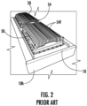
- FIGs. 1 and 2 illustrate an example of a prior art "active" base station antenna 10 that includes a pair of beamforming arrays and associated beamforming radios.
- the base station antenna 10 is typically mounted with the longitudinal axis L of the antenna 10 extending along a vertical axis (e.g., the longitudinal axis L may be generally perpendicular to a plane defined by the horizon) when the antenna 10 is mounted for normal operation.
- the front surface of the antenna 10 is mounted opposite the tower or other mounting structure, pointing toward the coverage area for the antenna 10.
- the antenna 10 includes a radome 11 and a top end cap 20.
- the antenna 10 also includes a bottom end cap 30 which includes a plurality of connectors 40 mounted therein. As shown, the radome 11 , top cap 20 and bottom cap 30 define an external housing 10h for the antenna 10.
- An antenna assembly is contained within the housing 10h.
- FIG. 2 illustrates that the antenna 10 can include one or more radios 50 that are mounted to the housing 10h.
- each radio 50 can include a (die cast) heat sink 54 that is mounted on the rear surface of the radio 50.
- the heat sinks 54 are thermally conductive and include a plurality of fins 54f. Heat generated in the radios 50 passes to the heat sink 54 and spreads to the fins 54f. As shown in FIG. 2 , the fins 54f are external to the antenna housing 10h. This allows the heat to pass from the fins 54f to the external environment. Further details of example conventional antennas can be found in co-pending WO2019/236203 and WO2020/072880 , the contents of which are hereby incorporated by reference as if recited in full herein.
- Embodiments of the present invention are directed to a base station antenna assembly that includes: a housing having a passive antenna assembly and a passive reflector in the housing; a plurality of mounting structure brackets coupled directly or indirectly to a rear of the housing and to a mounting structure; a mounting frame coupled to the plurality of mounting structure brackets; an active antenna module positioned at least partially between opposing long sides of the mounting frame; and at least one active antenna bracket with bracket legs that are slanted and coupled to the mounting frame and to the active antenna module whereby the mounting frame attaches the active antenna module to the housing of the base station antenna.
- Embodiments of the present invention are directed to a base station antenna assembly that includes: a housing having a passive antenna assembly and a passive reflector in the housing; a plurality of mounting structure brackets coupled directly or indirectly to a rear of the housing and to a mounting structure; a mounting frame coupled to the plurality of mounting structure brackets; an active antenna module positioned at least partially between opposing long sides of the mounting frame; at least one active antenna bracket with bracket legs that are coupled to the mounting frame and to the active antenna module whereby the mounting frame attaches the active antenna module to the housing of the base station antenna; and at a cover that is coupled to a top portion of the mounting frame and extends downward behind a rear of the housing, toward a top portion of the active antenna module to thereby provide critter resistant and/or debris resistant protection.
- the active antenna module can include a massive multiple input multiple output (mMIMO) antenna array of radiating elements positioned in front of an active reflector.
- mMIMO massive multiple input multiple output
- the passive reflector in the housing can be electrically coupled to the active reflector to thereby provide a common electrical ground.
- the mounting frame can have a top portion with a laterally extending lip.
- the plurality of mounting structure brackets can include a first mounting structure bracket and a longitudinally spaced apart second mounting structure bracket.
- the first mounting structure bracket can have a laterally extending ledge that slidably cooperates with the lip.
- the lip can have an upper surface and a lower surface with a forwardly facing laterally extending channel therebetween.
- the laterally extending ledge of the first mounting bracket can reside in the laterally extending channel of the lip.
- the active antenna module can provide 5G operation and the passive antenna of the base station antenna can provide 4G operation.
- the antenna device can be a radio, a filter, a calibration unit, an S-band antenna or combinations thereof and/or an active antenna module.
- Embodiments of the present invention provide base station antennas with respective passive antenna assemblies within a housing and that are configured to releasably couple to an external device such as, for example, an active antenna module that is at least partially external to the housing of the base station antenna/passive antenna housing.
- an external device such as, for example, an active antenna module that is at least partially external to the housing of the base station antenna/passive antenna housing.
- Still other embodiments are directed to a base station antenna assembly that includes: a housing of a base station antenna comprising a passive antenna assembly and a passive reflector in the housing; a plurality of mounting structure brackets coupled directly or indirectly to a rear of the housing and to a mounting structure (e.g., pole); a mounting frame coupled to the plurality of mounting structure brackets; an active antenna module positioned at least partially between opposing long sides of the mounting frame; at least one active antenna bracket coupled to the mounting frame and to the active antenna module whereby the mounting frame attaches the active antenna module to the housing of the base station antenna; and a cover that is coupled to a top portion of the mounting frame and that extends downward over an open space between a top portion of the mounting frame and a top of the active antenna module.
- the cover can have a length that is less than a length of the mounting frame and extends downward about a rear of the mounting frame.
- the cover can have a width that extends across a laterally extending open space at a top portion of the mounting frame above the active antenna module and between the right and left long sides of the mounting frame thereby providing a critter and/or debris resistant protection.
- a base station antenna assembly that includes: a housing of a base station antenna comprising a passive antenna assembly and a passive reflector in the housing; a plurality of mounting structure brackets coupled directly or indirectly to a rear of the housing and to a mounting structure; a mounting frame coupled to the plurality of mounting structure brackets; an active antenna module positioned at least partially between opposing long sides of the mounting frame; and an active antenna bracket with right and left side bracket arms that are slanted and project rearward from a laterally extending segment of the active antenna bracket.
- the right and left side bracket arms couple to the mounting frame, and the laterally extending segment is coupled to a rear surface of the active antenna module whereby the mounting frame attaches the active antenna module to the housing of the base station antenna.
- the mounting frame can have a pair of laterally spaced apart long sides with a rear facing surface.
- Each rear facing surface can have a plurality of longitudinally spaced apart mounting apertures positioned at different height positions, measured in a Z dimension corresponding to a front to back direction of the base station antenna.
- Different sets of the mounting apertures at respective corresponding height positions are configured to couple to different size or shape active antenna modules and/or active antenna brackets.
- the active antenna bracket can be configured to be selectively used in one of two use orientations, a first use orientation whereby the bracket arms are slanted downward and a second use orientation whereby the bracket arms are slanted upward.
- the bracket arms that are slanted downward can have a first mounting aperture that aligns with a first one of the plurality of mounting apertures of the rear facing surface, and in the second use orientation, the bracket arms are slanted upward and the first mounting aperture aligns with a second one of the plurality mounting apertures on the rear facing surface.
- Still other embodiments are directed to a base station antenna assembly that includes: a housing of a base station antenna comprising a passive antenna assembly and a passive reflector in the housing; a plurality of mounting structure brackets coupled directly or indirectly to a rear of the housing and to a mounting structure; a mounting frame coupled to the plurality of mounting structure brackets; an active antenna module positioned at least partially between opposing long sides of the mounting frame; at least one active antenna bracket coupled to the mounting frame and to the active antenna module whereby the mounting frame attaches the active antenna module to the housing of the base station antenna; and a spacer extending above a top of the active antenna module, behind a rear of a top portion of the housing.
- the spacer has a width that is greater than a length corresponding to a longitudinally extending direction of the base station antenna assembly.
- the spacer can have a plurality of laterally spaced apart apertures that are configured to allow fasteners to extend therethrough between a front of the mounting frame and the rear of the top portion of the housing.
- the spacer can extend between a top one of the plurality of mounting structures and the top portion of the rear of the housing.
- Additional embodiments are directed to a base station antenna that includes: a housing comprising a passive antenna, wherein the housing has a front radome and a rear radome; an active antenna module behind the rear radome of the housing; and a cover that resides outside of the housing and outside of the active antenna module, between the rear radome of the housing and a front of the active antenna module.
- the cover can have a 2-D or 3-D body.
- the cover can have a frequency selective surface/substrate.
- the cover can be configured to allow radio frequency signal transmitted from the active antenna module to propagate therethrough.
- the cover can be provided, at least in part, by netting or film.
- the mounting frame can be sized and configured to interchangeably serially couple to different configurations of active antenna modules.
- a top portion of the mounting frame can have a laterally extending lip.
- a base station antenna 100 will be described using terms that assume that the base station antenna 100 is mounted for use on a tower, pole or other mounting structure with the longitudinal axis L ( FIG. 1 ) of the antenna 100 ( FIG. 6 ) extending along a vertical axis and the front of the base station antenna 100 mounted opposite the tower, pole or other mounting structure pointing toward the target coverage area for the base station antenna 100 and the rear of the base station antenna 100 facing the tower or other mounting structure.
- the base station antenna 100 may not always be mounted so that the longitudinal axis L thereof extends along a vertical axis.
- the base station antenna 100 may be tilted slightly (e.g., less than 10°) with respect to the vertical axis so that the resultant antenna beams formed by the base station antenna 100 each have a small mechanical downtilt.
- an example mounting frame 60 configured to provide a mounting system for mounting a device behind the base station antenna 100 ( FIG. 6 ).
- the device can comprise filters and/or antenna systems, such as S-band antennas, and/or an active antenna module 110.
- the mounting frame 60 is configured to attach the device such as the active antenna module 110 to a base station antenna 100 ( FIG. 6 ) without requiring rails provided directly on the base station antenna to mount the frame 60 and/or by modifying the bracket structure providing the mounting interface for the (pole/tower) support structure mounting bracket for mounting the frame 60.
- active antenna module is used interchangeably with “active antenna unit” and "AAU” and refers to a cellular communications unit comprising radio circuitry and associated antenna elements that are capable of electronically adjusting the amplitude and/or phase of the subcomponents of an RF signal that are output to different radiating elements of an array or groups thereof.
- the active antenna module 110 comprises the radio circuitry and the radiating elements (e.g., a multi-input-multi-output (mMIMO) beamforming antenna array) and may include other components such as filters, a, calibration network, antenna interface signal group (AISG) controller and the like.
- mMIMO multi-input-multi-output
- the active antenna module 110 can be provided as a single integrated unit or provided as a plurality of stackable units, including, for example, first and second sub-units such as a radio sub-unit (box) with the radio circuitry and an antenna sub-unit (box) with a multi-column array of radiating elements and the first and second sub-units stackably attach together in a front to back direction of the base station antenna 100 , with the antenna unit closer to the front 100f (external radome) of the base station antenna 100 than the radio unit.
- first and second sub-units such as a radio sub-unit (box) with the radio circuitry and an antenna sub-unit (box) with a multi-column array of radiating elements and the first and second sub-units stackably attach together in a front to back direction of the base station antenna 100 , with the antenna unit closer to the front 100f (external radome) of the base station antenna 100 than the radio unit.
- passive antenna assembly refers to an antenna assembly having arrays of radiating elements that are coupled to radios that are external to the antenna, typically remote radio heads that are mounted in close proximity to the base station antenna 100 /housing 100h.
- the arrays of radiating elements included in the passive antenna assembly are configured to form static antenna beams.
- the passive antenna assembly can comprise radiating elements such as one or both low band radiating elements and/or mid-band or high band radiating elements.
- the passive antenna assembly 190 is mounted in the base station antenna housing 100h and the base station antenna housing 100h can releasably (detachably) couple (e.g., directly or indirectly attach) to one or more active antenna modules 110 that is/are separate from the passive antenna assembly 190.
- the mounting frame 60 comprises a top portion 60t , a bottom portion 60b and laterally spaced apart side portions 61 that extend between the top and bottom portions in a longitudinal direction.
- the mounting frame 60 can comprise an open region 62 extending between the top portion 60t and the bottom portion 60b and the laterally spaced apart side portions 61.
- the size of the open region 62 can vary and is not required to extend an entire length or width between the opposing sides 61. Additional details of the mounting system can be found in co-pending U.S. patent Application Serial Number 17/905,291 , the contents of which are hereby incorporated by reference as if recited in full herein.
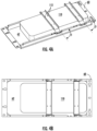
- the mounting frame 60 can be coupled to at least one active antenna bracket 150 , shown as first and second longitudinally spaced apart active antenna brackets, 150 1 , 150 2 , each with slanted bracket arms 152.
- a laterally extending segment 151 can have apertures 112 that receive fasteners to be attached to a rear 110r of an active antenna module 110 and the slanted bracket arms 152 are coupled to long sides 61 of the mounting frame 60.
- the mounting frame 60 is configured to couple to a passive antenna/base station antenna housing 100h with the active antenna module 110 behind a rear 100r of the housing 100h ( FIG. 6 ) according to embodiments of the present invention.
- FIGS. 4A and 4B show the respective brackets 150 1 ,150 2 in a first use orientation, with the slanted bracket arms 152 slanted upwards toward a top portion 60t of the mounting frame 60.
- FIGS. 4A and 4B show the same respective brackets 150 1 , 150 2 , but with the brackets in a second use orientation with the slanted bracket arms slanted downward toward a bottom 60b of the mounting frame 60 , oriented in a second use direction according to embodiments of the present invention.
- the long sides 61 of the mounting frame 60 have longitudinally spaced apart mounting apertures 61a.
- the slanted bracket arms 152 allow the bracket 150 to be coupled to different sets of the mounting apertures 61a on the long sides 61 of the mounting frame 60. This allows the mounting frame 60 to accommodate different configurations of active antenna modules 110 , such as shorter ones ( FIGS. 3A , 3B ) and longer ones ( FIGS. 4A , 4B ).
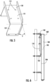
- the slanted bracket arms 152 can slant at an angle ⁇ between about 1 degree and about 45 degrees from the laterally extending segment 151 and/or a vertical use orientation and a free end can comprise mounting apertures 150a .
- the bracket 150 can be provided as a set of different brackets 150 , at least some of which have different slanted angles ⁇ to allow for additional mounting options for different shaped active antenna modules 110 for better gap spacing in a front-to-back direction ( FIG. 7 ).
- the slanted bracket arms 152 can provide a longitudinal offset relative to bracket arms that would be in-line with, and orthogonal to, the laterally extending segment 151.
- FIGS. 6 and 7 illustrate the mounting frame 60 coupled to the active antenna module 110 and residing behind a top portion of a rear 100r of the base station antenna 100 , each of which are mounted to a mounting structure (e.g., poled) using mounting structure brackets 160 , 162 .
- the top bracket 160 can have a lip 160l that receives a lip 64 of the mounting frame 60.
- a small gap, in a front-to-back (Z) direction may exist for some configurations of active antenna modules 110 and housing 100h , under the top bracket 160 and under the top of the housing 100h.
- the top portion 60t of the mounting frame 60 can provide the lip 64.
- the lip can include a plurality of laterally spaced apart apertures 65 , which may be provided as slots, which may be a circular region, merging into a narrower second region along its length (with its length oriented to extend in a width dimension of the AAU 110 and base station antenna 100 ).
- the apertures 65 receive fasteners that can extend downward.
- the lip 64 can have a free end facing in a forward direction.
- the different sets of mounting apertures 61a can be provided at different Z heights, corresponding to a front-to-back direction of the base station antenna 100 ( FIG. 6 ).
- the different sets of mounting apertures 61a can include sets A, B and C, each at different height positions, h1 , h2 , h3. Although shown as three sets, two sets or more than three sets can be used.
- the different sets A, B, C can include a first mounting aperture 61a and a second mounting aperture 61a , longitudinally spaced apart on each of a right long side 61 and similarly aligned spaced apart pairs 61a on a left long side 61 of the mounting frame 60.
- the first mounting aperture 61a of each set are serially arranged under and the second mounting aperture of each respective second set.
- the respective different sets of mounting apertures 61a can reside in different planes that are coplanar at heights h1 , h2 , h3 , corresponding to 1 mm to about 2 inches for the stepped positional differences, e.g., stepped increments, in some embodiments.
- the different heights can have a common stepped dimension or different stepped dimension, some with smaller and some with larger steps in the Z direction.
- FIG. 9 illustrates that a first set of the mounting apertures 61a can be provided on a fabricated stepped region which may be provided by a planar rear welded surface segment attached to an extruded body.
- the stepped regions providing the different heights for the different sets A, B, C of mounting apertures 61a can be provided in other manners, extruded, brazed, adhesively provided layers, and the like, as will be recognized by one of skill in the art.
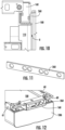
- a spacer 260 can be arranged at a top portion 100t of a rear 100r of the base station antenna, between the rear 100r of and the front 110f of the active antenna module 110.
- the spacer 260 can abut the rear 100r and can reside above the gap between the rear 100r and a front of the active antenna module 110 and provides an overlap in a front to back direction, with the active antenna module 110.
- the spacer 260 can be metal, non-metallic, foam, rubber or any suitable substrate or combinations of substrates.
- the spacer 260 can have a width dimension that is greater than a length dimension.
- the spacer 260 can reside in front of a top portion of the mounting frame 60 and adjacent the top 100t of the base station antenna 100 with the passive antenna therein.
- the spacer 260 can have a plurality of laterally spaced apart apertures that receive fasteners.
- the spacer 260 can have a length that is relatively short to extend a short distance above (e.g., 1 inch or less), below, or flush with a top 100t of the base station antenna 100 and terminate adjacent to but above the active antenna module 110.
- FIGS. 13A and 13B illustrate example overlap spacing depending on a mounting orientation of the spacer 260 with respect to the rear 100r of the base station antenna 100 and a front of the active antenna module 110 using the spacer 260 , a fastener and washer of lesser height/length.
- the spacer 260 can provide a debris barrier over the gap space so as to avoid performance loss if debris may drop into and/or wedge between the active antenna module 110 and a rear 100r of the base station antenna housing 100h.
- an open space A can exist between a top portion of the mounting frame 60 and a top portion of the active antenna module 110 , under the top 100t of the base station antenna 100 with the passive antenna 190 therein. It may be desirable to provide critter-resistance and/or debris-resistance protection by using a cover 360 to block this space A.
- FIGS. 16-18 show example covers 360.
- FIG. 16 shows a single piece cover 360 that is attached to the mounting frame 60 and extends in the space A between a top of the active antenna module 110 and the top of the mounting frame 60.
- FIG. 17 illustrates that the cover 360' maybe configured to extend perpendicular to the long sides 61 of the mounting frame 60 over a top of the active antenna module 110.
- FIG. 18 illustrates that the cover 360 may be provided by cover segments 360s that allow for customized sizing of the cover 360 depending on a size of the space A. The cover segments 360s can be coupled together or be closely spaced apart and reside over the space A.
- the cover 360 can extend laterally across the space and couple to each of the long sides 61.
- the cover 360 can be provided by any suitable material.
- the cover 360 can have a three-dimensional body.
- FIG. 19 illustrates that the cover 360 can be provided by a defined substrate such as a frequency selective surface/substrate comprising an array of unit cells, or a screen or grate configuration, and/or optionally netting and/or a film.
- a defined substrate such as a frequency selective surface/substrate comprising an array of unit cells, or a screen or grate configuration, and/or optionally netting and/or a film.
- the cover 360 can be transparent for the mMIMO radiating elements in the active antenna module 110.
- the cover 360 can be an external cover 360 that is outside of and between the rear 100r of the housing of the passive antenna 100 and the front radome of the active antenna module 110.
- the cover 360 can be held by other mounting structures and is not required to be coupled to the mounting frame 60 , nor be used with such a mounting frame 60.
- the (external) cover 360 can comprise a FSS (frequency selective surface) that is configured to be transparent to high-band signal frequency to thereby allow RF signal to propagate therethrough.
- FSS frequency selective surface
- the cover 360 can be or comprise metal, can be non-metallic, can comprise a dielectric, foam, rubber, a thin film, or any suitable substrate or combinations of substrates. Where the cover 360 is positioned in-line with (in front or behind the radio of the active antenna module 110 ), it may be non-metallic, such as plastic, to reduce PIM.
- the cover 360 can be provided with bird and/or other critter repellent coatings, odorants, color and/or patterned surfaces that can fend off or make it less desirable for visits from critters.
- the cover 360 can comprise barbs or other physical or visual repellent indicia.
- the mounting frame 60 can be configured to be a "multiple purpose" mounting frame 60 that can accommodate a plurality of different configurations of active antenna modules 110 using the different sets of mounting apertures 61a on the long sides thereof.
- Different active antenna modules 110 may be configured to have different radios, radiating elements or other components whereby the active antenna modules 110 can be different for different cellular service providers and even for the same cellular provider.
- the active antenna module 110 can be interchangeably replaced with another active antenna module 110 from the original equipment manufacturer (OEM) or from the same cellular communications service provider or from different cellular communications service providers.
- OEM original equipment manufacturer
- a plurality of different active antenna modules 110 that have different configurations, including different internal configurations and different external configurations can be interchangeably coupled to the base station antenna housing 100h.
- the different active antenna modules 110 can each have the same exterior (perimeter) footprint and connectors or may have different exterior footprints and/or connectors.
- the different active antenna modules 110 can have different depth dimensions (front to back) and/or different width (lateral) dimensions.
- a respective base station antenna 100 can, for example, accept different active antenna modules 110 from different service providers at a field installation and/or factory installation site using different adapter members or other mounting configurations that allow the interchangeable field installation/assembly.
- the base station antenna 100 /antenna housing 100h can thereby allow different active antenna modules 110 to be interchangeably installed, upgraded, or replaced.
- the base station antenna 100 can concurrently hold first and second active antenna units 110 , one above the other, in some embodiments.
- the antennas 100 may have a number of advantages over conventional antennas. As cellular operators upgrade their networks to support fifth generation (“5G”) service, the base station antennas that are being deployed are becoming increasingly complex. It is desirable to minimize antenna size and/or integrate increased number of antenna or antenna elements inside a single bases station antenna/external radome. For example, due to space constraints and/or allowable antenna counts on antenna towers of existing base stations, it may not be possible to simply add new antennas to support 5G service. Accordingly, cellular operators are opting to deploy antennas that support multiple generations of cellular service by including linear arrays of radiating elements that operate in a variety of different frequency bands in a single antenna.
- these antennas may include multi-column arrays of radiating elements that support active beamforming.
- Cellular operators are seeking to support all of these services in base station antennas that are comparable in size to conventional base station antennas that supported far fewer frequency bands.
- the active antenna modules 110 may also be readily replaced in the field. As is well known, base station antennas are typically mounted on towers, often hundreds of feet above the ground. Base station antennas may also be large, heavy and mounted on antenna mounts that extend outwardly from the tower. As such, replacing base station antennas may be difficult and expensive.
- the active antenna modules 110 with beamforming radios may be field installable and/or replaceable without the need to detach the base station antenna 100 from an antenna mount.
Landscapes
- Support Of Aerials (AREA)
- Transceivers (AREA)
Abstract
Description
- This application claims the benefit of and priority to
U.S. Provisional Application Serial Number 63/486,343, filed February 22, 2023 - The present invention generally relates to radio communications and, more particularly, to base station antennas for cellular communications systems.
- Cellular communications systems are well known in the art. In a cellular communications system, a geographic area is divided into a series of regions that are referred to as "cells" which are served by respective base stations. The base station may include one or more antennas that are configured to provide two-way radio frequency ("RF") communications with mobile subscribers that are within the cell served by the base station. In many cases, each cell is divided into "sectors." In one common configuration, a hexagonally shaped cell is divided into three 120° sectors in the azimuth plane, and each sector is served by one or more base station antennas that have an azimuth Half Power Beamwidth (HPBW) of approximately 65°. Typically, the base station antennas are mounted on a tower or other raised structure, with the radiation patterns (also referred to herein as "antenna beams") that are generated by the base station antennas directed outwardly. Base station antennas are often implemented as linear or planar phased arrays of radiating elements.
- In order to accommodate the increasing volume of cellular communications, cellular operators have added cellular service in a variety of new frequency bands. In order to increase capacity without further increasing the number of base station antennas, multi-band base station antennas have been introduced which include multiple linear arrays of radiating elements. Additionally, base station antennas are now being deployed that include "beamforming" arrays of radiating elements that include multiple columns of radiating elements. The radios for these beamforming arrays may be integrated into the antenna so that the antenna may perform active beamforming (i.e., the shapes of the antenna beams generated by the antenna may be adaptively changed to improve the performance of the antenna). These beamforming arrays typically operate in higher frequency bands, such as various portions of the 3.3-5.8 GHz frequency band. Antennas having integrated radios that can adjust the amplitude and/or phase of the sub-components of an RF signal that are transmitted through individual radiating elements or small groups thereof are referred to as "active antennas." Active antennas can generate narrowed beamwidth, high gain, antenna beams and can steer the generated antenna beams in different directions by changing the amplitudes and/or phases of the sub-components of RF signals that are transmitted through the antenna.
-
FIGs. 1 and2 illustrate an example of a prior art "active"base station antenna 10 that includes a pair of beamforming arrays and associated beamforming radios. Thebase station antenna 10 is typically mounted with the longitudinal axis L of theantenna 10 extending along a vertical axis (e.g., the longitudinal axis L may be generally perpendicular to a plane defined by the horizon) when theantenna 10 is mounted for normal operation. The front surface of theantenna 10 is mounted opposite the tower or other mounting structure, pointing toward the coverage area for theantenna 10. Theantenna 10 includes aradome 11 and atop end cap 20. Theantenna 10 also includes abottom end cap 30 which includes a plurality ofconnectors 40 mounted therein. As shown, theradome 11,top cap 20 andbottom cap 30 define anexternal housing 10h for theantenna 10. An antenna assembly is contained within thehousing 10h. -
FIG. 2 illustrates that theantenna 10 can include one ormore radios 50 that are mounted to thehousing 10h. As theradios 50 may generate significant amounts of heat, it may be appropriate to vent heat from the active antenna in order to prevent theradios 50 from overheating. Accordingly, eachradio 50 can include a (die cast)heat sink 54 that is mounted on the rear surface of theradio 50. Theheat sinks 54 are thermally conductive and include a plurality offins 54f. Heat generated in theradios 50 passes to theheat sink 54 and spreads to thefins 54f. As shown inFIG. 2 , thefins 54f are external to theantenna housing 10h. This allows the heat to pass from thefins 54f to the external environment. Further details of example conventional antennas can be found in co-pendingWO2019/236203 andWO2020/072880 , the contents of which are hereby incorporated by reference as if recited in full herein. - Embodiments of the present invention are directed to a base station antenna assembly that includes: a housing having a passive antenna assembly and a passive reflector in the housing; a plurality of mounting structure brackets coupled directly or indirectly to a rear of the housing and to a mounting structure; a mounting frame coupled to the plurality of mounting structure brackets; an active antenna module positioned at least partially between opposing long sides of the mounting frame; and at least one active antenna bracket with bracket legs that are slanted and coupled to the mounting frame and to the active antenna module whereby the mounting frame attaches the active antenna module to the housing of the base station antenna.
- Embodiments of the present invention are directed to a base station antenna assembly that includes: a housing having a passive antenna assembly and a passive reflector in the housing; a plurality of mounting structure brackets coupled directly or indirectly to a rear of the housing and to a mounting structure; a mounting frame coupled to the plurality of mounting structure brackets; an active antenna module positioned at least partially between opposing long sides of the mounting frame; at least one active antenna bracket with bracket legs that are coupled to the mounting frame and to the active antenna module whereby the mounting frame attaches the active antenna module to the housing of the base station antenna; and at a cover that is coupled to a top portion of the mounting frame and extends downward behind a rear of the housing, toward a top portion of the active antenna module to thereby provide critter resistant and/or debris resistant protection.
- The active antenna module can include a massive multiple input multiple output (mMIMO) antenna array of radiating elements positioned in front of an active reflector. The passive reflector in the housing can be electrically coupled to the active reflector to thereby provide a common electrical ground.
- The mounting frame can have a top portion with a laterally extending lip. The plurality of mounting structure brackets can include a first mounting structure bracket and a longitudinally spaced apart second mounting structure bracket. The first mounting structure bracket can have a laterally extending ledge that slidably cooperates with the lip.
- The lip can have an upper surface and a lower surface with a forwardly facing laterally extending channel therebetween. The laterally extending ledge of the first mounting bracket can reside in the laterally extending channel of the lip.
- The active antenna module can provide 5G operation and the passive antenna of the base station antenna can provide 4G operation.
- The antenna device can be a radio, a filter, a calibration unit, an S-band antenna or combinations thereof and/or an active antenna module.
- Embodiments of the present invention provide base station antennas with respective passive antenna assemblies within a housing and that are configured to releasably couple to an external device such as, for example, an active antenna module that is at least partially external to the housing of the base station antenna/passive antenna housing.
- Still other embodiments are directed to a base station antenna assembly that includes: a housing of a base station antenna comprising a passive antenna assembly and a passive reflector in the housing; a plurality of mounting structure brackets coupled directly or indirectly to a rear of the housing and to a mounting structure (e.g., pole); a mounting frame coupled to the plurality of mounting structure brackets; an active antenna module positioned at least partially between opposing long sides of the mounting frame; at least one active antenna bracket coupled to the mounting frame and to the active antenna module whereby the mounting frame attaches the active antenna module to the housing of the base station antenna; and a cover that is coupled to a top portion of the mounting frame and that extends downward over an open space between a top portion of the mounting frame and a top of the active antenna module.
- The cover can have a length that is less than a length of the mounting frame and extends downward about a rear of the mounting frame.
- The cover can have a width that extends across a laterally extending open space at a top portion of the mounting frame above the active antenna module and between the right and left long sides of the mounting frame thereby providing a critter and/or debris resistant protection.
- Yet other embodiments are directed to a base station antenna assembly that includes: a housing of a base station antenna comprising a passive antenna assembly and a passive reflector in the housing; a plurality of mounting structure brackets coupled directly or indirectly to a rear of the housing and to a mounting structure; a mounting frame coupled to the plurality of mounting structure brackets; an active antenna module positioned at least partially between opposing long sides of the mounting frame; and an active antenna bracket with right and left side bracket arms that are slanted and project rearward from a laterally extending segment of the active antenna bracket. The right and left side bracket arms couple to the mounting frame, and the laterally extending segment is coupled to a rear surface of the active antenna module whereby the mounting frame attaches the active antenna module to the housing of the base station antenna.
- The mounting frame can have a pair of laterally spaced apart long sides with a rear facing surface. Each rear facing surface can have a plurality of longitudinally spaced apart mounting apertures positioned at different height positions, measured in a Z dimension corresponding to a front to back direction of the base station antenna. Different sets of the mounting apertures at respective corresponding height positions are configured to couple to different size or shape active antenna modules and/or active antenna brackets.
- The active antenna bracket can be configured to be selectively used in one of two use orientations, a first use orientation whereby the bracket arms are slanted downward and a second use orientation whereby the bracket arms are slanted upward.
- In the first use orientation, the bracket arms that are slanted downward can have a first mounting aperture that aligns with a first one of the plurality of mounting apertures of the rear facing surface, and in the second use orientation, the bracket arms are slanted upward and the first mounting aperture aligns with a second one of the plurality mounting apertures on the rear facing surface.
- Still other embodiments are directed to a base station antenna assembly that includes: a housing of a base station antenna comprising a passive antenna assembly and a passive reflector in the housing; a plurality of mounting structure brackets coupled directly or indirectly to a rear of the housing and to a mounting structure; a mounting frame coupled to the plurality of mounting structure brackets; an active antenna module positioned at least partially between opposing long sides of the mounting frame; at least one active antenna bracket coupled to the mounting frame and to the active antenna module whereby the mounting frame attaches the active antenna module to the housing of the base station antenna; and a spacer extending above a top of the active antenna module, behind a rear of a top portion of the housing. The spacer has a width that is greater than a length corresponding to a longitudinally extending direction of the base station antenna assembly.
- The spacer can have a plurality of laterally spaced apart apertures that are configured to allow fasteners to extend therethrough between a front of the mounting frame and the rear of the top portion of the housing.
- The spacer can extend between a top one of the plurality of mounting structures and the top portion of the rear of the housing.
- Additional embodiments are directed to a base station antenna that includes: a housing comprising a passive antenna, wherein the housing has a front radome and a rear radome; an active antenna module behind the rear radome of the housing; and a cover that resides outside of the housing and outside of the active antenna module, between the rear radome of the housing and a front of the active antenna module.
- The cover can have a 2-D or 3-D body.
- The cover can have a frequency selective surface/substrate.
- The cover can be configured to allow radio frequency signal transmitted from the active antenna module to propagate therethrough.
- The cover can be provided, at least in part, by netting or film.
- The mounting frame can be sized and configured to interchangeably serially couple to different configurations of active antenna modules.
- A top portion of the mounting frame can have a laterally extending lip.
-
-
FIG. 1 is a perspective view of a prior art base station antenna. -
FIG. 2 is a back view of the prior art base station antenna ofFIG. 1 . -
FIG. 3A is a rear, side perspective view of a mounting frame coupled to active antenna brackets with slanted bracket arms to attach an active antenna module to a passive antenna/base station antenna housing according to embodiments of the present invention. -
FIG. 3B is rear view of the devices shown inFIG. 3A . -
FIG. 4A is a rear, side perspective view of the devices shown inFIG. 3A but with the active antenna brackets with the slanted bracket arms oriented in a second use direction according to embodiments of the present invention. -
FIG. 4B is a rear view of the devices shown inFIG. 4A . -
FIG. 5 is an enlarged side perspective view of the bracket shown inFIGS. 3A, 3B ,4A, and 4B . -
FIG. 6 is a side view of an example base station antenna coupled to a mounting structure (pole) with the mounting frame coupled to an active antenna module positioned behind the passive antenna/base station antenna housing according to embodiments of the present invention -
FIG. 7 is a greatly enlarged view of a top portion of the devices shown inFIG. 6 according to embodiments of the present invention. -
FIG. 8 is a rear, side perspective view of an example mounting frame according to embodiments of the present invention. -
FIG. 9 is an enlarged view of one set of mounting apertures shown on the long sides of the mounting frame inFIG. 8 . -
FIG. 10 is a side view of a rear top portion of a base station antenna with a spacer between the rear of the housing and a top one of the mounting structure brackets shown inFIG. 6 according to embodiments of the present invention. -
FIG. 11 is a side perspective view of the spacer shown inFIG. 10 according to embodiments of the present invention. -
FIG. 12 is a top end, perspective view of the devices shown inFIG. 10 according to embodiments of the present invention. -
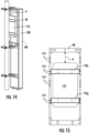
FIGS. 13A and 13B are side views of top rear portions of the base station antenna shown inFIG. 6 with the spacer in two different positions relative to the rear of the housing and each providing an overlap with an underlying top portion of the active antenna module according to embodiments of the present invention. -
FIG. 14 is a rear, side perspective view of another example base station antenna assembly with the active antenna module arranged on the mounting frame so as to have an open space A in a top portion of the mounting frame above the active antenna module according to embodiments of the present invention. -
FIG. 15 is a rear view of the active antenna module and mounting frame shown inFIG. 14 with the open space A, shown without the base station antenna housing/passive antenna according to embodiments of the present invention. -
FIGS. 16-18 are rear side perspective views of example mounting frames with covers configured to cover the open space to thereby occlude critters and/or debris according to embodiments of the present invention. -
FIG. 19 is a rear view of an example mounting frame with cover over an open space of the mounting frame between a top portion of the mounting frame and a top of the active antenna module according to embodiments of the present invention. - In the description that follows, a
base station antenna 100 will be described using terms that assume that thebase station antenna 100 is mounted for use on a tower, pole or other mounting structure with the longitudinal axis L (FIG. 1 ) of the antenna 100 (FIG. 6 ) extending along a vertical axis and the front of thebase station antenna 100 mounted opposite the tower, pole or other mounting structure pointing toward the target coverage area for thebase station antenna 100 and the rear of thebase station antenna 100 facing the tower or other mounting structure. It will be appreciated that thebase station antenna 100 may not always be mounted so that the longitudinal axis L thereof extends along a vertical axis. For example, thebase station antenna 100 may be tilted slightly (e.g., less than 10°) with respect to the vertical axis so that the resultant antenna beams formed by thebase station antenna 100 each have a small mechanical downtilt. - Referring to
FIGS. 3A, 3B ,4A and 4B , anexample mounting frame 60 configured to provide a mounting system for mounting a device behind the base station antenna 100 (FIG. 6 ). The device can comprise filters and/or antenna systems, such as S-band antennas, and/or anactive antenna module 110. In some embodiments, the mountingframe 60 is configured to attach the device such as theactive antenna module 110 to a base station antenna 100 (FIG. 6 ) without requiring rails provided directly on the base station antenna to mount theframe 60 and/or by modifying the bracket structure providing the mounting interface for the (pole/tower) support structure mounting bracket for mounting theframe 60. The term "active antenna module" is used interchangeably with "active antenna unit" and "AAU" and refers to a cellular communications unit comprising radio circuitry and associated antenna elements that are capable of electronically adjusting the amplitude and/or phase of the subcomponents of an RF signal that are output to different radiating elements of an array or groups thereof. Theactive antenna module 110 comprises the radio circuitry and the radiating elements (e.g., a multi-input-multi-output (mMIMO) beamforming antenna array) and may include other components such as filters, a, calibration network, antenna interface signal group (AISG) controller and the like. Theactive antenna module 110 can be provided as a single integrated unit or provided as a plurality of stackable units, including, for example, first and second sub-units such as a radio sub-unit (box) with the radio circuitry and an antenna sub-unit (box) with a multi-column array of radiating elements and the first and second sub-units stackably attach together in a front to back direction of thebase station antenna 100, with the antenna unit closer to the front 100f (external radome) of thebase station antenna 100 than the radio unit. - Further details of example
base station antennas 100 with anantenna housing 100h that includes a passive antenna assembly 190 (FIGS. 6 ,14 ) can be found inU.S. Patent Number 11,482,774 base station antenna 100/housing 100h. The arrays of radiating elements included in the passive antenna assembly are configured to form static antenna beams. The passive antenna assembly can comprise radiating elements such as one or both low band radiating elements and/or mid-band or high band radiating elements. Thepassive antenna assembly 190 is mounted in the basestation antenna housing 100h and the basestation antenna housing 100h can releasably (detachably) couple (e.g., directly or indirectly attach) to one or moreactive antenna modules 110 that is/are separate from thepassive antenna assembly 190. - Turning again to
FIGs. 3A-3B , the mountingframe 60 comprises atop portion 60t, abottom portion 60b and laterally spaced apartside portions 61 that extend between the top and bottom portions in a longitudinal direction. The mountingframe 60 can comprise anopen region 62 extending between thetop portion 60t and thebottom portion 60b and the laterally spaced apartside portions 61. The size of theopen region 62 can vary and is not required to extend an entire length or width between the opposing sides 61. Additional details of the mounting system can be found in co-pendingU.S. patent Application Serial Number 17/905,291 , the contents of which are hereby incorporated by reference as if recited in full herein. - Referring to
FIGs. 3A, 3B ,4A and 4B , the mountingframe 60 can be coupled to at least oneactive antenna bracket 150, shown as first and second longitudinally spaced apart active antenna brackets, 1501, 1502, each with slantedbracket arms 152. A laterally extendingsegment 151 can haveapertures 112 that receive fasteners to be attached to a rear 110r of anactive antenna module 110 and the slantedbracket arms 152 are coupled tolong sides 61 of the mountingframe 60. The mountingframe 60 is configured to couple to a passive antenna/basestation antenna housing 100h with theactive antenna module 110 behind a rear 100r of thehousing 100h (FIG. 6 ) according to embodiments of the present invention.FIGS. 3A and 3B show therespective brackets bracket arms 152 slanted upwards toward atop portion 60t of the mountingframe 60.FIGS. 4A and 4B show the samerespective brackets frame 60, oriented in a second use direction according to embodiments of the present invention. - The
long sides 61 of the mountingframe 60 have longitudinally spaced apart mountingapertures 61a. The slantedbracket arms 152 allow thebracket 150 to be coupled to different sets of the mountingapertures 61a on thelong sides 61 of the mountingframe 60. This allows the mountingframe 60 to accommodate different configurations ofactive antenna modules 110, such as shorter ones (FIGS. 3A, 3B ) and longer ones (FIGS. 4A, 4B ). - The slanted
bracket arms 152 can slant at an angle β between about 1 degree and about 45 degrees from the laterally extendingsegment 151 and/or a vertical use orientation and a free end can comprise mountingapertures 150a. Thebracket 150 can be provided as a set ofdifferent brackets 150, at least some of which have different slanted angles β to allow for additional mounting options for different shapedactive antenna modules 110 for better gap spacing in a front-to-back direction (FIG. 7 ). The slantedbracket arms 152 can provide a longitudinal offset relative to bracket arms that would be in-line with, and orthogonal to, the laterally extendingsegment 151. -
FIGS. 6 and7 illustrate the mountingframe 60 coupled to theactive antenna module 110 and residing behind a top portion of a rear 100r of thebase station antenna 100, each of which are mounted to a mounting structure (e.g., poled) using mountingstructure brackets top bracket 160 can have a lip 160l that receives alip 64 of the mountingframe 60. A small gap, in a front-to-back (Z) direction may exist for some configurations ofactive antenna modules 110 andhousing 100h, under thetop bracket 160 and under the top of thehousing 100h. - Referring to
FIGS. 3A and6 , thetop portion 60t of the mountingframe 60 can provide thelip 64. The lip can include a plurality of laterally spaced apart apertures 65, which may be provided as slots, which may be a circular region, merging into a narrower second region along its length (with its length oriented to extend in a width dimension of theAAU 110 and base station antenna 100). Theapertures 65 receive fasteners that can extend downward. However, other attachment configurations and members may be used. Thelip 64 can have a free end facing in a forward direction. - Referring to
FIG. 8 , the different sets of mountingapertures 61a can be provided at different Z heights, corresponding to a front-to-back direction of the base station antenna 100 (FIG. 6 ). The different sets of mountingapertures 61a can include sets A, B and C, each at different height positions, h1, h2, h3. Although shown as three sets, two sets or more than three sets can be used. The different sets A, B, C can include a first mountingaperture 61a and asecond mounting aperture 61a, longitudinally spaced apart on each of a rightlong side 61 and similarly aligned spaced apart pairs 61a on a leftlong side 61 of the mountingframe 60. Thefirst mounting aperture 61a of each set are serially arranged under and the second mounting aperture of each respective second set. The respective different sets of mountingapertures 61a can reside in different planes that are coplanar at heights h1, h2, h3, corresponding to 1 mm to about 2 inches for the stepped positional differences, e.g., stepped increments, in some embodiments. The different heights can have a common stepped dimension or different stepped dimension, some with smaller and some with larger steps in the Z direction. -
FIG. 9 illustrates that a first set of the mountingapertures 61a can be provided on a fabricated stepped region which may be provided by a planar rear welded surface segment attached to an extruded body. However, the stepped regions providing the different heights for the different sets A, B, C of mountingapertures 61a can be provided in other manners, extruded, brazed, adhesively provided layers, and the like, as will be recognized by one of skill in the art. - Turning now to
FIGS. 10-12 , in some embodiments aspacer 260 can be arranged at atop portion 100t of a rear 100r of the base station antenna, between the rear 100r of and the front 110f of theactive antenna module 110. Thespacer 260 can abut the rear 100r and can reside above the gap between the rear 100r and a front of theactive antenna module 110 and provides an overlap in a front to back direction, with theactive antenna module 110. Thespacer 260 can be metal, non-metallic, foam, rubber or any suitable substrate or combinations of substrates. Thespacer 260 can have a width dimension that is greater than a length dimension. Thespacer 260 can reside in front of a top portion of the mountingframe 60 and adjacent the top 100t of thebase station antenna 100 with the passive antenna therein. Thespacer 260 can have a plurality of laterally spaced apart apertures that receive fasteners. Thespacer 260 can have a length that is relatively short to extend a short distance above (e.g., 1 inch or less), below, or flush with a top 100t of thebase station antenna 100 and terminate adjacent to but above theactive antenna module 110. -
FIGS. 13A and 13B illustrate example overlap spacing depending on a mounting orientation of thespacer 260 with respect to the rear 100r of thebase station antenna 100 and a front of theactive antenna module 110 using thespacer 260, a fastener and washer of lesser height/length. Thespacer 260 can provide a debris barrier over the gap space so as to avoid performance loss if debris may drop into and/or wedge between theactive antenna module 110 and a rear 100r of the basestation antenna housing 100h. - Turning now to
FIGS. 14 and 15 , depending on a size and position of anactive antenna module 110 on the mountingframe 60, an open space A can exist between a top portion of the mountingframe 60 and a top portion of theactive antenna module 110, under the top 100t of thebase station antenna 100 with thepassive antenna 190 therein. It may be desirable to provide critter-resistance and/or debris-resistance protection by using acover 360 to block this space A. -
FIGS. 16-18 show example covers 360.FIG. 16 shows asingle piece cover 360 that is attached to the mountingframe 60 and extends in the space A between a top of theactive antenna module 110 and the top of the mountingframe 60.FIG. 17 illustrates that the cover 360' maybe configured to extend perpendicular to thelong sides 61 of the mountingframe 60 over a top of theactive antenna module 110.FIG. 18 illustrates that thecover 360 may be provided bycover segments 360s that allow for customized sizing of thecover 360 depending on a size of the space A. Thecover segments 360s can be coupled together or be closely spaced apart and reside over the space A. - The
cover 360 can extend laterally across the space and couple to each of the long sides 61. Thecover 360 can be provided by any suitable material. Thecover 360 can have a three-dimensional body. -
FIG. 19 illustrates that thecover 360 can be provided by a defined substrate such as a frequency selective surface/substrate comprising an array of unit cells, or a screen or grate configuration, and/or optionally netting and/or a film. - The
cover 360 can be transparent for the mMIMO radiating elements in theactive antenna module 110. - Thus, the
cover 360 can be anexternal cover 360 that is outside of and between the rear 100r of the housing of thepassive antenna 100 and the front radome of theactive antenna module 110. Thecover 360 can be held by other mounting structures and is not required to be coupled to the mountingframe 60, nor be used with such a mountingframe 60. - In some embodiments, the (external)
cover 360 can comprise a FSS (frequency selective surface) that is configured to be transparent to high-band signal frequency to thereby allow RF signal to propagate therethrough. For examples of FSS structures, see co-pendingU.S. Patent Application Serial No. 17/787,619 , the contents of which are hereby incorporated by reference as if recited in full herein. - The
cover 360 can be or comprise metal, can be non-metallic, can comprise a dielectric, foam, rubber, a thin film, or any suitable substrate or combinations of substrates. Where thecover 360 is positioned in-line with (in front or behind the radio of the active antenna module 110), it may be non-metallic, such as plastic, to reduce PIM. - The
cover 360 can be provided with bird and/or other critter repellent coatings, odorants, color and/or patterned surfaces that can fend off or make it less desirable for visits from critters. Thecover 360 can comprise barbs or other physical or visual repellent indicia. - Thus, the mounting
frame 60 can be configured to be a "multiple purpose" mountingframe 60 that can accommodate a plurality of different configurations ofactive antenna modules 110 using the different sets of mountingapertures 61a on the long sides thereof. - Different
active antenna modules 110 may be configured to have different radios, radiating elements or other components whereby theactive antenna modules 110 can be different for different cellular service providers and even for the same cellular provider. Theactive antenna module 110 can be interchangeably replaced with anotheractive antenna module 110 from the original equipment manufacturer (OEM) or from the same cellular communications service provider or from different cellular communications service providers. Thus, a plurality of differentactive antenna modules 110 that have different configurations, including different internal configurations and different external configurations, can be interchangeably coupled to the basestation antenna housing 100h. The differentactive antenna modules 110 can each have the same exterior (perimeter) footprint and connectors or may have different exterior footprints and/or connectors. The differentactive antenna modules 110 can have different depth dimensions (front to back) and/or different width (lateral) dimensions. A respectivebase station antenna 100 can, for example, accept differentactive antenna modules 110 from different service providers at a field installation and/or factory installation site using different adapter members or other mounting configurations that allow the interchangeable field installation/assembly. Thebase station antenna 100/antenna housing 100h can thereby allow differentactive antenna modules 110 to be interchangeably installed, upgraded, or replaced. Thebase station antenna 100 can concurrently hold first and secondactive antenna units 110, one above the other, in some embodiments. - The
antennas 100 may have a number of advantages over conventional antennas. As cellular operators upgrade their networks to support fifth generation ("5G") service, the base station antennas that are being deployed are becoming increasingly complex. It is desirable to minimize antenna size and/or integrate increased number of antenna or antenna elements inside a single bases station antenna/external radome. For example, due to space constraints and/or allowable antenna counts on antenna towers of existing base stations, it may not be possible to simply add new antennas to support 5G service. Accordingly, cellular operators are opting to deploy antennas that support multiple generations of cellular service by including linear arrays of radiating elements that operate in a variety of different frequency bands in a single antenna. Thus, for example, it is common now for cellular operators to request a single base station antenna that supports service in three, four or even five or more different frequency bands. Moreover, in order to support 5G service, these antennas may include multi-column arrays of radiating elements that support active beamforming. Cellular operators are seeking to support all of these services in base station antennas that are comparable in size to conventional base station antennas that supported far fewer frequency bands. - The
active antenna modules 110 may also be readily replaced in the field. As is well known, base station antennas are typically mounted on towers, often hundreds of feet above the ground. Base station antennas may also be large, heavy and mounted on antenna mounts that extend outwardly from the tower. As such, replacing base station antennas may be difficult and expensive. Theactive antenna modules 110 with beamforming radios may be field installable and/or replaceable without the need to detach thebase station antenna 100 from an antenna mount. - Embodiments of the present invention have been described above with reference to the accompanying drawings, in which embodiments of the invention are shown. This invention may, however, be embodied in many different forms and should not be construed as limited to the embodiments set forth herein. Rather, these embodiments are provided so that this disclosure will be thorough and complete, and will fully convey the scope of the invention to those skilled in the art. Like numbers refer to like elements throughout.
- It will be understood that, although the terms first, second, etc. may be used herein to describe various elements, these elements should not be limited by these terms. These terms are only used to distinguish one element from another. For example, a first element could be termed a second element, and, similarly, a second element could be termed a first element, without departing from the scope of the present invention. As used herein, the term "and/or" includes any and all combinations of one or more of the associated listed items.
- It will be understood that when an element is referred to as being "on" another element, it can be directly on the other element or intervening elements may also be present. In contrast, when an element is referred to as being "directly on" another element, there are no intervening elements present. It will also be understood that when an element is referred to as being "connected" or "coupled" to another element, it can be directly connected or coupled to the other element or intervening elements may be present. In contrast, when an element is referred to as being "directly connected" or "directly coupled" to another element, there are no intervening elements present. Other words used to describe the relationship between elements should be interpreted in a like fashion (i.e., "between" versus "directly between", "adjacent" versus "directly adjacent", etc.)
- Relative terms such as "below" or "above" or "upper" or "lower" or "horizontal" or "vertical" may be used herein to describe a relationship of one element, layer or region to another element, layer or region as illustrated in the figures. It will be understood that these terms are intended to encompass different orientations of the device in addition to the orientation depicted in the figures.
- The term "about" used with respect to a number refers to a variation of +/-10%.
- The terminology used herein is for the purpose of describing particular embodiments only and is not intended to be limiting of the invention. As used herein, the singular forms "a", "an" and "the" are intended to include the plural forms as well, unless the context clearly indicates otherwise. It will be further understood that the terms "comprises" "comprising," "includes" and/or "including" when used herein, specify the presence of stated features, operations, elements, and/or components, but do not preclude the presence or addition of one or more other features, operations, elements, components, and/or groups thereof.
- Aspects and elements of all of the embodiments disclosed above can be combined in any way and/or combination with aspects or elements of other embodiments to provide a plurality of additional embodiments.
Claims (15)
- A base station antenna assembly, comprising:a housing of a base station antenna comprising a passive antenna assembly and a passive reflector in the housing;a plurality of mounting structure brackets coupled directly or indirectly to a rear of the housing and to a mounting structure (e.g., pole);a mounting frame coupled to the plurality of mounting structure brackets;an active antenna module positioned at least partially between opposing long sides of the mounting frame;at least one active antenna bracket coupled to the mounting frame and to the active antenna module whereby the mounting frame attaches the active antenna module to the housing of the base station antenna; anda cover that is coupled to a top portion of the mounting frame and that extends downward over an open space between a top portion of the mounting frame and a top of the active antenna module.
- The base station antenna assembly of Claim 1, wherein the cover has a length that is less than a length of the mounting frame and extends downward about a rear of the mounting frame.
- The base station antenna assembly of either Claim 1 or Claim 2, wherein the cover has a width that extends across a laterally extending open space at a top portion of the mounting frame above the active antenna module and between the right and left long sides of the mounting frame thereby providing critter and/or debris resistant protection, optionally wherein the cover comprises netting.
- A base station antenna assembly, comprising:a housing of a base station antenna comprising a passive antenna assembly and a passive reflector in the housing;a plurality of mounting structure brackets coupled directly or indirectly to a rear of the housing and to a mounting structure;a mounting frame coupled to the plurality of mounting structure brackets;
an active antenna module positioned at least partially between opposing long sides of the mounting frame; andan active antenna bracket with right and left side bracket arms that are slanted and project rearward from a laterally extending segment of the active antenna bracket, wherein the right and left side bracket arms couple to the mounting frame, and wherein the laterally extending segment is coupled to a rear surface of the active antenna module whereby the mounting frame attaches the active antenna module to the housing of the base station antenna. - The base station antenna of any one of the previous Claims, wherein the mounting frame comprises a pair of laterally spaced apart long sides with a rear facing surface, each rear facing surface comprising a plurality of longitudinally spaced apart mounting apertures positioned at different height positions, measured in a Z dimension corresponding to a front to back direction of the base station antenna, and wherein different sets of the mounting apertures at respective corresponding height positions are configured to couple to different size or shape active antenna brackets and/or active antenna modules.
- The base station antenna of Claim 5, wherein the active antenna bracket is configured to be selectively used in one of two use orientations, a first use orientation whereby the bracket arms are slanted downward and a second use orientation whereby the bracket arms are slanted upward.
- The base station antenna of either Claim 5 or Claim 6, wherein in the first use orientation the bracket arms that are slanted downward comprise a first mounting aperture that aligns with a first one of the plurality of mounting apertures of the rear facing surface, and wherein in the second use orientation, the bracket arms are slanted upward and the first mounting aperture aligns with a second one of the plurality mounting apertures on the rear facing surface.
- A base station antenna assembly, comprising:a housing of a base station antenna comprising a passive antenna assembly and a passive reflector in the housing;a plurality of mounting structure brackets coupled directly or indirectly to a rear of the housing and to a mounting structure;a mounting frame coupled to the plurality of mounting structure brackets;
an active antenna module positioned at least partially between opposing long sides of the mounting frame;at least one active antenna bracket coupled to the mounting frame and to the active antenna module whereby the mounting frame attaches the active antenna module to the housing of the base station antenna; anda spacer extending above a top of the active antenna module, behind a rear of a top portion of the housing, wherein the spacer has a width that is greater than a length corresponding to a longitudinally extending direction of the base station antenna assembly. - The base station antenna of Claim 8, wherein the spacer comprises a plurality of laterally spaced apart apertures that are configured to allow fasteners to extend therethrough between a front of the mounting frame and the rear of the top portion of the housing.
- The base station antenna of either Claim 8 or Claim 9, wherein the spacer extends between a top one of the plurality of mounting structures and the top portion of the rear of the housing.
- A base station antenna comprising:a housing comprising a passive antenna, wherein the housing has a front radome and a rear radome;an active antenna module behind the rear radome of the housing; anda cover that resides outside of the housing and outside of the active antenna module, between the rear radome of the housing and a front of the active antenna module.
- The base station antenna of Any one of Claims 1 to 3 or Claim 11, wherein the cover comprises a frequency selective surface and/or substrate.
- The base station antenna of any one of Claims 1 to 3 or Claim 11 or Claim 12, wherein the cover is configured to allow radio frequency signal transmitted from the active antenna module to propagate therethrough.
- The base station antenna assembly of any of Claims 1-10, wherein the mounting frame is sized and configured to interchangeably serially couple to different configurations of active antenna modules.
- The base station antenna assembly of any of Claims 1-10 or 14, wherein a top portion of the mounting frame includes a laterally extending lip.
Applications Claiming Priority (1)
| Application Number | Priority Date | Filing Date | Title |
|---|---|---|---|
| US202363486343P | 2023-02-22 | 2023-02-22 |
Publications (2)
| Publication Number | Publication Date |
|---|---|
| EP4421978A2 true EP4421978A2 (en) | 2024-08-28 |
| EP4421978A3 EP4421978A3 (en) | 2024-11-06 |
Family
ID=89977461
Family Applications (1)
| Application Number | Title | Priority Date | Filing Date |
|---|---|---|---|
| EP24157911.9A Pending EP4421978A3 (en) | 2023-02-22 | 2024-02-15 | Base station antennas having an active antenna module(s) and related mounting systems and methods |
Country Status (1)
| Country | Link |
|---|---|
| EP (1) | EP4421978A3 (en) |
Citations (3)
| Publication number | Priority date | Publication date | Assignee | Title |
|---|---|---|---|---|
| WO2019236203A2 (en) | 2018-05-15 | 2019-12-12 | Commscope Technologies Llc | Base station antennas having fully embedded radios and housings with integrated heat sink structures |
| WO2020072880A1 (en) | 2018-10-05 | 2020-04-09 | Commscope Technologies Llc | Reconfigurable multi-band base station antennas having self-contained sub-modules |
| US11482774B2 (en) | 2020-03-24 | 2022-10-25 | Commscope Technologies Llc | Base station antennas having an active antenna module and related devices and methods |
Family Cites Families (6)
| Publication number | Priority date | Publication date | Assignee | Title |
|---|---|---|---|---|
| KR102140293B1 (en) * | 2014-02-24 | 2020-08-11 | 주식회사 케이엠더블유 | Multi band antenna device |
| WO2021126327A1 (en) * | 2019-12-18 | 2021-06-24 | Commscope Technologies Llc | Base station antenna units having arrays spanning multiple antennas that are connected by jumper cables |
| EP4089832A4 (en) * | 2020-01-09 | 2024-01-24 | KMW Inc. | Base station antenna device and adapter thereof |
| EP4356484A4 (en) * | 2021-06-16 | 2025-04-30 | Outdoor Wireless Networks LLC | Base station antennas having an active antenna module(s) and related devices and methods |
| CN216818640U (en) * | 2021-09-29 | 2022-06-24 | 康普技术有限责任公司 | Base station antenna arrangement, base station antenna and antenna assembly for base station antenna |
| CN217334387U (en) * | 2022-06-01 | 2022-08-30 | 康普技术有限责任公司 | Base Station Antennas and Base Station Antenna Assemblies |
-
2024
- 2024-02-15 EP EP24157911.9A patent/EP4421978A3/en active Pending
Patent Citations (3)
| Publication number | Priority date | Publication date | Assignee | Title |
|---|---|---|---|---|
| WO2019236203A2 (en) | 2018-05-15 | 2019-12-12 | Commscope Technologies Llc | Base station antennas having fully embedded radios and housings with integrated heat sink structures |
| WO2020072880A1 (en) | 2018-10-05 | 2020-04-09 | Commscope Technologies Llc | Reconfigurable multi-band base station antennas having self-contained sub-modules |
| US11482774B2 (en) | 2020-03-24 | 2022-10-25 | Commscope Technologies Llc | Base station antennas having an active antenna module and related devices and methods |
Also Published As
| Publication number | Publication date |
|---|---|
| EP4421978A3 (en) | 2024-11-06 |
Similar Documents
| Publication | Publication Date | Title |
|---|---|---|
| US11335995B2 (en) | Base station antennas including supplemental arrays | |
| US12362461B2 (en) | Base station antennas having at least one grid reflector and related devices | |
| EP3861592B1 (en) | Reconfigurable multi-band base station antennas having self-contained sub-modules | |
| CN110612639B (en) | Base station antenna with parasitic coupling elements | |
| CN111786081B (en) | Multi-band base station antenna with integrated array | |
| US12374770B2 (en) | Base station antennas having an active antenna module(s) and related mounting systems and methods | |
| US12469982B2 (en) | Base station antennas having an active antenna module(s) and related devices and methods | |
| US11888220B2 (en) | Base station antennas having bottom end caps with angled connector ports | |
| US12057622B2 (en) | Connectivity and field replaceability of radios mounted on base station antennas | |
| EP4421978A2 (en) | Base station antennas having an active antenna module(s) and related mounting systems and methods | |
| US11646502B2 (en) | Multi-band base station antenna | |
| EP3869612A1 (en) | Connectivity and field replaceability of radios mounted on base station antennas | |
| US20260031547A1 (en) | Base station antennas having an active antenna module(s) and related mounting systems and methods | |
| WO2026035597A1 (en) | Radiating elements for multiband base station antennas having cavity phase shifters and related linear array assemblies and base station antennas |
Legal Events
| Date | Code | Title | Description |
|---|---|---|---|
| PUAI | Public reference made under article 153(3) epc to a published international application that has entered the european phase |
Free format text: ORIGINAL CODE: 0009012 |
|
| STAA | Information on the status of an ep patent application or granted ep patent |
Free format text: STATUS: REQUEST FOR EXAMINATION WAS MADE |
|
| 17P | Request for examination filed |
Effective date: 20240215 |
|
| AK | Designated contracting states |
Kind code of ref document: A2 Designated state(s): AL AT BE BG CH CY CZ DE DK EE ES FI FR GB GR HR HU IE IS IT LI LT LU LV MC ME MK MT NL NO PL PT RO RS SE SI SK SM TR |
|
| RAP1 | Party data changed (applicant data changed or rights of an application transferred) |
Owner name: OUTDOOR WIRELESS NETWORKS LLC |
|
| PUAL | Search report despatched |
Free format text: ORIGINAL CODE: 0009013 |
|
| AK | Designated contracting states |
Kind code of ref document: A3 Designated state(s): AL AT BE BG CH CY CZ DE DK EE ES FI FR GB GR HR HU IE IS IT LI LT LU LV MC ME MK MT NL NO PL PT RO RS SE SI SK SM TR |
|
| RIC1 | Information provided on ipc code assigned before grant |
Ipc: H01Q 3/02 20060101ALN20240930BHEP Ipc: H01Q 3/06 20060101ALI20240930BHEP Ipc: H01Q 19/02 20060101ALI20240930BHEP Ipc: H01Q 1/42 20060101ALI20240930BHEP Ipc: H01Q 1/24 20060101ALI20240930BHEP Ipc: H01Q 1/12 20060101AFI20240930BHEP |
|
| GRAP | Despatch of communication of intention to grant a patent |
Free format text: ORIGINAL CODE: EPIDOSNIGR1 |
|
| STAA | Information on the status of an ep patent application or granted ep patent |
Free format text: STATUS: GRANT OF PATENT IS INTENDED |
|
| RIC1 | Information provided on ipc code assigned before grant |
Ipc: H01Q 1/12 20060101AFI20251113BHEP Ipc: H01Q 1/24 20060101ALI20251113BHEP Ipc: H01Q 1/42 20060101ALI20251113BHEP Ipc: H01Q 19/02 20060101ALI20251113BHEP Ipc: H01Q 3/06 20060101ALI20251113BHEP Ipc: H01Q 3/02 20060101ALN20251113BHEP |
|
| INTG | Intention to grant announced |
Effective date: 20251208 |
|
| RIC1 | Information provided on ipc code assigned before grant |
Ipc: H01Q 1/12 20060101AFI20251128BHEP Ipc: H01Q 1/42 20060101ALI20251128BHEP Ipc: H01Q 1/24 20060101ALN20251128BHEP Ipc: H01Q 3/06 20060101ALN20251128BHEP |