EP4421956A1 - Battery drying device - Google Patents
Battery drying device Download PDFInfo
- Publication number
- EP4421956A1 EP4421956A1 EP23158678.5A EP23158678A EP4421956A1 EP 4421956 A1 EP4421956 A1 EP 4421956A1 EP 23158678 A EP23158678 A EP 23158678A EP 4421956 A1 EP4421956 A1 EP 4421956A1
- Authority
- EP
- European Patent Office
- Prior art keywords
- battery
- moisture
- opening
- regeneration
- drying device
- Prior art date
- Legal status (The legal status is an assumption and is not a legal conclusion. Google has not performed a legal analysis and makes no representation as to the accuracy of the status listed.)
- Granted
Links
Images

Classifications
-
- H—ELECTRICITY
- H01—ELECTRIC ELEMENTS
- H01M—PROCESSES OR MEANS, e.g. BATTERIES, FOR THE DIRECT CONVERSION OF CHEMICAL ENERGY INTO ELECTRICAL ENERGY
- H01M50/00—Constructional details or processes of manufacture of the non-active parts of electrochemical cells other than fuel cells, e.g. hybrid cells
- H01M50/10—Primary casings; Jackets or wrappings
- H01M50/14—Primary casings; Jackets or wrappings for protecting against damage caused by external factors
- H01M50/141—Primary casings; Jackets or wrappings for protecting against damage caused by external factors for protecting against humidity
-
- H—ELECTRICITY
- H01—ELECTRIC ELEMENTS
- H01M—PROCESSES OR MEANS, e.g. BATTERIES, FOR THE DIRECT CONVERSION OF CHEMICAL ENERGY INTO ELECTRICAL ENERGY
- H01M50/00—Constructional details or processes of manufacture of the non-active parts of electrochemical cells other than fuel cells, e.g. hybrid cells
- H01M50/20—Mountings; Secondary casings or frames; Racks, modules or packs; Suspension devices; Shock absorbers; Transport or carrying devices; Holders
- H01M50/233—Mountings; Secondary casings or frames; Racks, modules or packs; Suspension devices; Shock absorbers; Transport or carrying devices; Holders characterised by physical properties of casings or racks, e.g. dimensions
- H01M50/24—Mountings; Secondary casings or frames; Racks, modules or packs; Suspension devices; Shock absorbers; Transport or carrying devices; Holders characterised by physical properties of casings or racks, e.g. dimensions adapted for protecting batteries from their environment, e.g. from corrosion
-
- B—PERFORMING OPERATIONS; TRANSPORTING
- B01—PHYSICAL OR CHEMICAL PROCESSES OR APPARATUS IN GENERAL
- B01D—SEPARATION
- B01D53/00—Separation of gases or vapours; Recovering vapours of volatile solvents from gases; Chemical or biological purification of waste gases, e.g. engine exhaust gases, smoke, fumes, flue gases, aerosols
- B01D53/26—Drying gases or vapours
- B01D53/261—Drying gases or vapours by adsorption
-
- H—ELECTRICITY
- H01—ELECTRIC ELEMENTS
- H01M—PROCESSES OR MEANS, e.g. BATTERIES, FOR THE DIRECT CONVERSION OF CHEMICAL ENERGY INTO ELECTRICAL ENERGY
- H01M10/00—Secondary cells; Manufacture thereof
- H01M10/42—Methods or arrangements for servicing or maintenance of secondary cells or secondary half-cells
- H01M10/52—Removing gases inside the secondary cell, e.g. by absorption
-
- H—ELECTRICITY
- H01—ELECTRIC ELEMENTS
- H01M—PROCESSES OR MEANS, e.g. BATTERIES, FOR THE DIRECT CONVERSION OF CHEMICAL ENERGY INTO ELECTRICAL ENERGY
- H01M50/00—Constructional details or processes of manufacture of the non-active parts of electrochemical cells other than fuel cells, e.g. hybrid cells
- H01M50/20—Mountings; Secondary casings or frames; Racks, modules or packs; Suspension devices; Shock absorbers; Transport or carrying devices; Holders
- H01M50/249—Mountings; Secondary casings or frames; Racks, modules or packs; Suspension devices; Shock absorbers; Transport or carrying devices; Holders specially adapted for aircraft or vehicles, e.g. cars or trains
-
- H—ELECTRICITY
- H01—ELECTRIC ELEMENTS
- H01M—PROCESSES OR MEANS, e.g. BATTERIES, FOR THE DIRECT CONVERSION OF CHEMICAL ENERGY INTO ELECTRICAL ENERGY
- H01M50/00—Constructional details or processes of manufacture of the non-active parts of electrochemical cells other than fuel cells, e.g. hybrid cells
- H01M50/30—Arrangements for facilitating escape of gases
- H01M50/317—Re-sealable arrangements
-
- H—ELECTRICITY
- H01—ELECTRIC ELEMENTS
- H01M—PROCESSES OR MEANS, e.g. BATTERIES, FOR THE DIRECT CONVERSION OF CHEMICAL ENERGY INTO ELECTRICAL ENERGY
- H01M50/00—Constructional details or processes of manufacture of the non-active parts of electrochemical cells other than fuel cells, e.g. hybrid cells
- H01M50/30—Arrangements for facilitating escape of gases
- H01M50/394—Gas-pervious parts or elements
-
- H—ELECTRICITY
- H01—ELECTRIC ELEMENTS
- H01M—PROCESSES OR MEANS, e.g. BATTERIES, FOR THE DIRECT CONVERSION OF CHEMICAL ENERGY INTO ELECTRICAL ENERGY
- H01M2220/00—Batteries for particular applications
- H01M2220/20—Batteries in motive systems, e.g. vehicle, ship, plane
-
- Y—GENERAL TAGGING OF NEW TECHNOLOGICAL DEVELOPMENTS; GENERAL TAGGING OF CROSS-SECTIONAL TECHNOLOGIES SPANNING OVER SEVERAL SECTIONS OF THE IPC; TECHNICAL SUBJECTS COVERED BY FORMER USPC CROSS-REFERENCE ART COLLECTIONS [XRACs] AND DIGESTS
- Y02—TECHNOLOGIES OR APPLICATIONS FOR MITIGATION OR ADAPTATION AGAINST CLIMATE CHANGE
- Y02E—REDUCTION OF GREENHOUSE GAS [GHG] EMISSIONS, RELATED TO ENERGY GENERATION, TRANSMISSION OR DISTRIBUTION
- Y02E60/00—Enabling technologies; Technologies with a potential or indirect contribution to GHG emissions mitigation
- Y02E60/10—Energy storage using batteries
Definitions
- Embodiments to a battery drying device for a battery to a battery with a battery drying device, to a vehicle having a battery with a battery drying device, and to a method of operating a battery drying device.
- a battery drying device for a battery is known from DE 10 2014 203 927 A1 .
- the battery drying device has a housing which is inserted into an opening in a battery housing of a battery, hence the battery drying device being fully integrated into the battery housing.
- the battery drying device includes a drying agent that adsorbs moisture that enters the battery drying device via incoming air from inside the battery housing.
- the battery drying device is equipped with a heating device with which the drying agent can be heated and adsorbed moisture can be released.
- a heating device with which the drying agent can be heated and adsorbed moisture can be released.
- the battery drying device can be used for drying a battery, for example a vehicle battery in vehicles.
- the vehicle battery is used for general power supply in the vehicle and/or for driving an electric motor used to drive the vehicle.
- the battery drying device can be used to efficiently remove moisture before it enters the interior of a battery or from the interior of the battery.
- the battery drying device has a drying housing in which a moisture adsorbing agent or drying agent is accommodated.
- An inlet opening is provided in the drying housing, which is covered by a membrane that keeps out liquid, in particular water, but could be permeable to water in the gaseous state.
- the membrane in the inlet opening enables pressure compensation in the interior of a battery housing of a battery, for example, in case of pressure differences due to a temperature change of the air in the battery housing. At the same time, the membrane prevents water entry from the outside into the battery drying device and into the battery.
- connection opening is also provided in the drying housing, the connection opening enabling a flow connection to the battery housing of the battery.
- a moisture adsorber means is arranged in the flow path between the inlet opening and the connecting opening, the moisture adsorber means dividing the interior of the drying housing in to separate chambers.
- An adjustable connection valve is inserted into the connection opening, which can be adjusted between a closed position and an open position.
- the inlet opening and the connection opening are located in the drying housing in such a way that the moisture adsorbent is arranged in the flow path between these openings. This ensures that both the air from the outside flowing in via the inlet opening and the air from the battery housing flowing out via the connection opening are adsorbed in the moisture adsorber means.
- a heating device is integrated into the battery drying device, by means of which the moisture adsorber means can be heated in order to remove the adsorbed moisture from the moisture adsorber means and thereby regenerate the moisture adsorber means.
- the heating means is designed to be electrically operable. During regular operation, the heating means is not active so that moisture can be adsorbed in the moisture adsorber means. This state corresponds to the operating mode in which the connecting valve is in an open position.
- a further opening is integrated in the drying housing, which has the function of a regeneration opening and which is not connected to the battery housing.
- a flow connection with the environment can be established via the regeneration opening.
- An adjustable regeneration valve is inserted into the regeneration opening, which can be adjusted between a closed position and an open position. In the operating mode, the regeneration valve is closed.
- a regeneration mode is activated in which the connection valve located in the connection opening to the battery housing is set to a closed position, and at the same time the regeneration valve in the regeneration opening is set to the open position.
- the heating device is actuated in the regeneration mode. Due to the closed connection valve, it is ensured that the air in the drying housing loaded with moisture from the moisture adsorber means does not enter the battery housing, but is rather discharged to the environment via the open regeneration valve and the regeneration opening.
- the heating device is switched off, the regeneration valve is closed and the connecting valve is opened again, whereupon the battery drying device is in the operating mode again.
- the regeneration opening and the inlet opening covered by the membrane are located on the same side of the moisture adsorber means.
- the heating device which serves to heat the moisture adsorber means in the regeneration mode, is designed, for example, as an electric heating rod.
- the battery drying device includes an electrically operated pump which serves to generate an air flow in the regeneration mode.
- the air flow can be directed through the moisture adsorber means, thereby significantly increasing the efficiency of drying the moisture adsorber means in the regeneration mode.
- the air flow is directed through the moisture adsorber means and can be discharged into the environment via the open regeneration opening.
- the electrically driven pump is integrated into the drying housing. This has the advantage that the pump is protected from environmental influences and no additional space is required for the pump.
- the drying housing has a ventilation opening with an adjustable ventilation valve arranged therein, the ventilation opening and the regeneration opening being located on opposite sides of the moisture adsorber means.
- the ventilation opening In the operating mode, the ventilation opening is closed, and in the regeneration mode, the ventilation opening is open so that a flow of air from the environment can be directed through the moisture adsorber means via the regeneration opening and discharged back into the environment via the ventilation opening.
- This design with ventilation opening and regeneration opening on opposite sides of the moisture adsorber means is combined in particular with the electrically operated pump, which is located for example on the same side as the moisture adsorber means as well as the regeneration opening. When the pump is actuated, air is drawn in from the environment and passed through the moisture adsorber means, whereupon the moisture-laden air is returned to the environment via the regeneration opening. In operating mode, both the ventilation opening and the regeneration opening are closed.
- a control unit and a power supply unit may be associated with the battery drying device, wherein individual controllable units of the battery drying device are controlled via the control unit, in particular the valves and the heating device.
- the electrical power required for the control and the change of state of the individual controllable units is provided via the power supply unit.
- Another aspect of the embodiments relates to a battery, in particular a vehicle battery having a battery drying device as described above.
- the battery drying device is located outside the battery housing, the drying housing and the battery housing advantageously being adjacent to each other.
- the flow connection is made via the connection opening, which is provided in the drying housing.
- the battery housing may also have a corresponding connection opening.
- the embodiments further relate to a vehicle having a predescribed battery with which a predescribed battery drying device is associated.
- the embodiments relate to a method of operating a pre-described battery drying device.
- the moisture adsorber means is dried in a regeneration mode by moving the connection valve to the closed position and the regeneration valve to the open position, whereupon the heating means is actuated.
- the battery drying device may be operated in an operating mode without regenerating the moisture adsorbent means and without actuating the heating means as long as the connecting valve is in the open position and the regeneration valve is in the closed position.
- FIG. 1 schematically depicts a battery 1, for example a vehicle battery for an electric drive motor in a vehicle.
- the battery 1 includes a battery housing 2 in which battery cells are accommodated.
- a pressure relief valve 3 is integrated into the battery housing 2, which serves as an emergency degassing unit for reducing an increased internal pressure in the battery housing 2.
- a battery drying device 4 is associated with the battery 1 for adsorbing moisture in the air passing through the battery drying device 4.
- a drying housing 5 of the battery drying device 4 an inlet opening 6 with a membrane 7 is arranged, through which ambient air flows into the battery drying device 4 and further into the interior of the battery housing 2.
- the membrane 7 prevents water in liquid form from passing, but it is possible for water in gaseous form to pass through the membrane 7.
- the water in gaseous form is at least partially removed from the air flow through the battery drying device 4.
- connection opening 8 which is opposite the inlet opening 6 and which is aligned with a corresponding opening in the battery housing 2.
- An adjustable connection valve 9 is inserted in the connection opening 8, which can be adjusted between an open position and a closed position.
- a moisture adsorber means 10 is arranged inside the drying housing 5 in the flow path of the air passing through the drying housing 5 which adsorbs the moisture in the air flow.
- a heating device 11 is integrated into the moisture adsorber means 10, for example a heating rod.
- a regeneration opening 12 is provided in the drying housing 5, in which an adjustable regeneration valve 13 is integrated.
- the regeneration opening 12 and the inlet opening 6 in are located on the same side of the moisture adsorber means 10, with respect to the air flow passed through it, and is thus located on the side facing away from the connection opening 8.
- the battery drying device 4 can be operated in a regular operation mode and in a regeneration mode.
- the connection valve 9 is open and the regeneration valve 13 is closed, so that ambient air can pass through the inlet opening 6 with the membrane 7.
- the moisture adsorber means 10 adsorbs the moisture in the air, and subsequently the air cleaned of the moisture enters the interior of the battery housing 2.
- the connecting valve 9 is closed and the regeneration valve 13 is open.
- the heating device 11 is actuated so that the moisture adsorber means 10 is heated and moisture is released from the moisture adsorber means 10 into the air in the drying housing 5, which can be released into the environment through the opened regeneration opening 12.
- the regeneration valve 13 is closed again and the connecting valve 9 is opened and the heating device 11 is switched off.
- the battery drying device 4 is in the now again in the operating mode.
- Fig. 2 shows another embodiment of a battery drying device 4 which, as in the first embodiment, is located on the side of a battery housing 2 of a battery 1.
- the battery drying device 4 has an inlet opening 6 with a membrane 7 in a drying housing 5.
- battery housing 2 has a connection opening 8 with a connection valve 9.
- a moisture adsorber means 10 with an integrated heating device 11 is located between the inlet opening 6 and the connection opening 8.
- a regeneration opening 12 with a regeneration valve 13 is located adjacent to the inlet opening 6.
- the design corresponds to that of the first embodiment.
- the battery drying device 4 has a ventilation opening 14 with an integrated, adjustable ventilation valve 15, the ventilation opening 14 being located at the end of a housing socket 16 which is formed integrally with the drying housing 5 and branches between the moisture adsorber means 10 and the connection opening 8.
- An electric pump 17 is integrated in the housing socket 16. When activating pump 17, an air flow is generated from the environment through the housing socket 16 to the interior of the battery drying device 4.
- the regeneration valve 13 and the ventilation valve 15 are closed and the connection valve 9 is open. Both the heating device 11 and the electric pump 17 are switched off. Air can flow into the battery drying device 4 from the environment via the inlet opening 6 and the membrane 7.
- connection valve 9 In the regeneration mode, the connection valve 9 is closed, and at the same time the regeneration valve 13 and the ventilation valve 15 are opened.
- the heating device 11 is switched on and the electric pump 17 is actuated so that an air flow is drawn from the environment into the housing socket 16. This air flow passes through the moisture adsorber means 10, thereby ensuring effective drying of the moisture adsorber means 10.
- an electric pump 17 is also provided, which is located in a housing socket 16 with a ventilation opening 14 at its end.
- the housing socket 16 branches upstream of the moisture adsorber means 10.
- the housing socket 16 with the ventilation opening 14 is located opposite the regeneration opening 12 and is located on the same side of the moisture adsorber means 10 as the regeneration opening 12 as well as the inlet opening 6.
Landscapes
- Chemical & Material Sciences (AREA)
- Chemical Kinetics & Catalysis (AREA)
- General Chemical & Material Sciences (AREA)
- Electrochemistry (AREA)
- Engineering & Computer Science (AREA)
- Manufacturing & Machinery (AREA)
- Aviation & Aerospace Engineering (AREA)
- Analytical Chemistry (AREA)
- Oil, Petroleum & Natural Gas (AREA)
- Drying Of Gases (AREA)
Abstract
Description
- Embodiments to a battery drying device for a battery, to a battery with a battery drying device, to a vehicle having a battery with a battery drying device, and to a method of operating a battery drying device.
- A battery drying device for a battery is known from
DE 10 2014 203 927 A1 . The battery drying device has a housing which is inserted into an opening in a battery housing of a battery, hence the battery drying device being fully integrated into the battery housing. The battery drying device includes a drying agent that adsorbs moisture that enters the battery drying device via incoming air from inside the battery housing. - The battery drying device is equipped with a heating device with which the drying agent can be heated and adsorbed moisture can be released. During this regeneration process, an opening in battery drying device to the interior of the battery housing is closed and, at the same time, an outflow opening is opened through which the moisture from the drying agent can escape into the environment.
- It is an object of the embodiments to operate a battery drying device with high efficiency over a long period of time.
- The battery drying device according to the embodiments can be used for drying a battery, for example a vehicle battery in vehicles. The vehicle battery is used for general power supply in the vehicle and/or for driving an electric motor used to drive the vehicle.
- The battery drying device can be used to efficiently remove moisture before it enters the interior of a battery or from the interior of the battery. For this purpose, the battery drying device has a drying housing in which a moisture adsorbing agent or drying agent is accommodated. An inlet opening is provided in the drying housing, which is covered by a membrane that keeps out liquid, in particular water, but could be permeable to water in the gaseous state. The membrane in the inlet opening enables pressure compensation in the interior of a battery housing of a battery, for example, in case of pressure differences due to a temperature change of the air in the battery housing. At the same time, the membrane prevents water entry from the outside into the battery drying device and into the battery.
- A connection opening is also provided in the drying housing, the connection opening enabling a flow connection to the battery housing of the battery. A moisture adsorber means is arranged in the flow path between the inlet opening and the connecting opening, the moisture adsorber means dividing the interior of the drying housing in to separate chambers. An adjustable connection valve is inserted into the connection opening, which can be adjusted between a closed position and an open position.
- The inlet opening and the connection opening are located in the drying housing in such a way that the moisture adsorbent is arranged in the flow path between these openings. This ensures that both the air from the outside flowing in via the inlet opening and the air from the battery housing flowing out via the connection opening are adsorbed in the moisture adsorber means.
- A heating device is integrated into the battery drying device, by means of which the moisture adsorber means can be heated in order to remove the adsorbed moisture from the moisture adsorber means and thereby regenerate the moisture adsorber means. In particular, the heating means is designed to be electrically operable. During regular operation, the heating means is not active so that moisture can be adsorbed in the moisture adsorber means. This state corresponds to the operating mode in which the connecting valve is in an open position.
- A further opening is integrated in the drying housing, which has the function of a regeneration opening and which is not connected to the battery housing. In particular, a flow connection with the environment can be established via the regeneration opening. An adjustable regeneration valve is inserted into the regeneration opening, which can be adjusted between a closed position and an open position. In the operating mode, the regeneration valve is closed.
- To regenerate the moisture adsorber means, a regeneration mode is activated in which the connection valve located in the connection opening to the battery housing is set to a closed position, and at the same time the regeneration valve in the regeneration opening is set to the open position. The heating device is actuated in the regeneration mode. Due to the closed connection valve, it is ensured that the air in the drying housing loaded with moisture from the moisture adsorber means does not enter the battery housing, but is rather discharged to the environment via the open regeneration valve and the regeneration opening. As soon as the regeneration mode is finished, the heating device is switched off, the regeneration valve is closed and the connecting valve is opened again, whereupon the battery drying device is in the operating mode again.
- In an advantageous embodiment, the regeneration opening and the inlet opening covered by the membrane are located on the same side of the moisture adsorber means. However, a configuration in which the inlet opening and the regeneration opening are located on opposite sides of the moisture adsorber means is also possible. The heating device, which serves to heat the moisture adsorber means in the regeneration mode, is designed, for example, as an electric heating rod.
- According to still another advantageous embodiment, the battery drying device includes an electrically operated pump which serves to generate an air flow in the regeneration mode. The air flow can be directed through the moisture adsorber means, thereby significantly increasing the efficiency of drying the moisture adsorber means in the regeneration mode. The air flow is directed through the moisture adsorber means and can be discharged into the environment via the open regeneration opening.
- Advantageously, the electrically driven pump is integrated into the drying housing. This has the advantage that the pump is protected from environmental influences and no additional space is required for the pump.
- According to a further advantageous embodiment, the drying housing has a ventilation opening with an adjustable ventilation valve arranged therein, the ventilation opening and the regeneration opening being located on opposite sides of the moisture adsorber means. In the operating mode, the ventilation opening is closed, and in the regeneration mode, the ventilation opening is open so that a flow of air from the environment can be directed through the moisture adsorber means via the regeneration opening and discharged back into the environment via the ventilation opening. This design with ventilation opening and regeneration opening on opposite sides of the moisture adsorber means is combined in particular with the electrically operated pump, which is located for example on the same side as the moisture adsorber means as well as the regeneration opening. When the pump is actuated, air is drawn in from the environment and passed through the moisture adsorber means, whereupon the moisture-laden air is returned to the environment via the regeneration opening. In operating mode, both the ventilation opening and the regeneration opening are closed.
- A control unit and a power supply unit may be associated with the battery drying device, wherein individual controllable units of the battery drying device are controlled via the control unit, in particular the valves and the heating device. The electrical power required for the control and the change of state of the individual controllable units is provided via the power supply unit.
- Another aspect of the embodiments relates to a battery, in particular a vehicle battery having a battery drying device as described above. The battery drying device is located outside the battery housing, the drying housing and the battery housing advantageously being adjacent to each other. The flow connection is made via the connection opening, which is provided in the drying housing. The battery housing may also have a corresponding connection opening.
- The embodiments further relate to a vehicle having a predescribed battery with which a predescribed battery drying device is associated.
- Finally, the embodiments relate to a method of operating a pre-described battery drying device. In the method, the moisture adsorber means is dried in a regeneration mode by moving the connection valve to the closed position and the regeneration valve to the open position, whereupon the heating means is actuated. Conversely, the battery drying device may be operated in an operating mode without regenerating the moisture adsorbent means and without actuating the heating means as long as the connecting valve is in the open position and the regeneration valve is in the closed position.
- A description will now be given as a non-limiting example of a form of several embodiments of a battery drying device. Reference will be made to the attached drawings, in which:
-
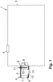
Figure 1 is a schematic representation of a battery drying device next to a battery housing; -
Figure 2 is a battery drying device in another embodiment; and -
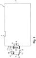
Figure 3 a battery drying device in yet another embodiment - In the figures, same components are provided with the same reference numerals.
-
Figure 1 schematically depicts a battery 1, for example a vehicle battery for an electric drive motor in a vehicle. The battery 1 includes abattery housing 2 in which battery cells are accommodated. Apressure relief valve 3 is integrated into thebattery housing 2, which serves as an emergency degassing unit for reducing an increased internal pressure in thebattery housing 2. - A battery drying device 4 is associated with the battery 1 for adsorbing moisture in the air passing through the battery drying device 4. In a drying
housing 5 of the battery drying device 4, aninlet opening 6 with amembrane 7 is arranged, through which ambient air flows into the battery drying device 4 and further into the interior of thebattery housing 2. Themembrane 7 prevents water in liquid form from passing, but it is possible for water in gaseous form to pass through themembrane 7. The water in gaseous form is at least partially removed from the air flow through the battery drying device 4. - In the drying
housing 5 of the battery drying device 4, there is also provided aconnection opening 8 which is opposite theinlet opening 6 and which is aligned with a corresponding opening in thebattery housing 2. Anadjustable connection valve 9 is inserted in theconnection opening 8, which can be adjusted between an open position and a closed position. - Inside the drying housing 5 a moisture adsorber means 10 is arranged in the flow path of the air passing through the drying
housing 5 which adsorbs the moisture in the air flow. Aheating device 11 is integrated into the moisture adsorber means 10, for example a heating rod. - A
regeneration opening 12 is provided in the dryinghousing 5, in which anadjustable regeneration valve 13 is integrated. Theregeneration opening 12 and theinlet opening 6 in are located on the same side of the moisture adsorber means 10, with respect to the air flow passed through it, and is thus located on the side facing away from theconnection opening 8. - The battery drying device 4 can be operated in a regular operation mode and in a regeneration mode. In the regular operation mode, the
connection valve 9 is open and theregeneration valve 13 is closed, so that ambient air can pass through theinlet opening 6 with themembrane 7. The moisture adsorber means 10 adsorbs the moisture in the air, and subsequently the air cleaned of the moisture enters the interior of thebattery housing 2. - In the regeneration mode, the connecting
valve 9 is closed and theregeneration valve 13 is open. At the same time, theheating device 11 is actuated so that the moisture adsorber means 10 is heated and moisture is released from the moisture adsorber means 10 into the air in the dryinghousing 5, which can be released into the environment through the openedregeneration opening 12. After completion of the regeneration process, which is carried out for example at regular time intervals, theregeneration valve 13 is closed again and the connectingvalve 9 is opened and theheating device 11 is switched off. The battery drying device 4 is in the now again in the operating mode. -
Fig. 2 shows another embodiment of a battery drying device 4 which, as in the first embodiment, is located on the side of abattery housing 2 of a battery 1. The battery drying device 4 has aninlet opening 6 with amembrane 7 in a dryinghousing 5. At the distal end,battery housing 2 has aconnection opening 8 with aconnection valve 9. A moisture adsorber means 10 with anintegrated heating device 11 is located between theinlet opening 6 and theconnection opening 8. Aregeneration opening 12 with aregeneration valve 13 is located adjacent to theinlet opening 6. In this respect, the design corresponds to that of the first embodiment. - Furthermore, the battery drying device 4 has a
ventilation opening 14 with an integrated,adjustable ventilation valve 15, theventilation opening 14 being located at the end of ahousing socket 16 which is formed integrally with the dryinghousing 5 and branches between the moisture adsorber means 10 and theconnection opening 8. Anelectric pump 17 is integrated in thehousing socket 16. When activatingpump 17, an air flow is generated from the environment through thehousing socket 16 to the interior of the battery drying device 4. - In the regular operation mode, the
regeneration valve 13 and theventilation valve 15 are closed and theconnection valve 9 is open. Both theheating device 11 and theelectric pump 17 are switched off. Air can flow into the battery drying device 4 from the environment via theinlet opening 6 and themembrane 7. - In the regeneration mode, the
connection valve 9 is closed, and at the same time theregeneration valve 13 and theventilation valve 15 are opened. In addition, theheating device 11 is switched on and theelectric pump 17 is actuated so that an air flow is drawn from the environment into thehousing socket 16. This air flow passes through the moisture adsorber means 10, thereby ensuring effective drying of the moisture adsorber means 10. - In the embodiment example according to
Fig. 3 , anelectric pump 17 is also provided, which is located in ahousing socket 16 with aventilation opening 14 at its end. In this embodiment example, thehousing socket 16 branches upstream of the moisture adsorber means 10. Thehousing socket 16 with theventilation opening 14 is located opposite theregeneration opening 12 and is located on the same side of the moisture adsorber means 10 as theregeneration opening 12 as well as theinlet opening 6. -
- 1 battery
- 2 battery housing
- 3 pressure relief valve
- 4 battery drying device
- 5 drying housing
- 6 inlet opening
- 7 membrane
- 8 connection opening
- 9 connection valve
- 10 moisture adsorber means
- 11 heating device
- 12 regeneration opening
- 13 regeneration valve
- 14 ventilation opening
- 15 ventilation valve
- 16 housing socket
- 17 pump
Claims (10)
- A battery drying device (4) comprising:a membrane (7) disposed external to a battery housing (2) of a battery (1), and configured to prevent liquid water from passing through the membrane (7) and to allow gaseous water to pass through the membrane (7);a moisture adsorber means (10) disposed external to the battery housing (2) and downstream from the membrane (7), and configured to absorb moisture in the gaseous water;an adjustable connection valve (9) disposed adjacent to the battery housing (2) and downstream from the moisture adsorber means (10), and configured to:in a regular operation mode, be open and allow air from which the moisture is absorbed by the moisture adsorber means (10) into the battery housing (2); andin a regeneration mode, be closed; andan adjustable regeneration valve (13) interposed between the membrane (7) and the moisture adsorber means (10) and configured to:in the regeneration mode, be open and allow air between the membrane (7) and the moisture adsorber means (10) to be released into an environment external to the battery housing (2); andin the regular operation mode, be closed position.
- The battery drying device (4) according to claim 1, further comprising a heating device (11) integrated into the moisture adsorber means (10), and configured to:in the regeneration mode, heat the moisture adsorber means (10) so that the moisture is released from the moisture adsorber means (10) into the air between the membrane (7) and the moisture adsorber means (10); andin the regular operation mode, be switched off.
- The battery drying device (4) according to claim 1 or 2, further comprising a drying housing (5) disposed external to the battery housing (2), and comprising:an inlet opening (6) at which the membrane (7) is disposed;a connection opening (8) at which the moisture adsorber means (10) is disposed; anda regeneration opening (12) interposed between the inlet opening (6) and the connection opening (8) and at which the adjustable regeneration valve (13) is disposed
- The battery drying device (4) according to claim 3, further comprising an electrically operated pump (17) interposed between the moisture adsorber means (10) and the adjustable connection valve (9), and configured to:in the regeneration mode, generate a drying air flow for the moisture adsorber means (10); andin the regular operation mode, be switched off.
- The battery drying device (4) according to claim 4, wherein the drying housing (5) further comprises a ventilation opening (14), the ventilation opening (14) and the regeneration opening (12) respectively being arranged on opposite sides of the moisture adsorber means (10),the battery drying device further comprises an adjustable ventilation valve (15) disposed adjacent to the ventilation opening (14), and configured to:in the regeneration mode, be open and allow air from the environment into the ventilation opening (14); andin the regular operation mode, be closed, andthe electrically operated pump (17) is disposed downstream from the ventilation opening (14), and is further configured to draw the air allowed into the ventilation opening (14).
- The battery drying device (4) according to claim 3, further comprising an electrically operated pump (17) interposed between the membrane (7) and the moisture adsorber means (10), and configured to:in the regeneration mode, generate a drying air flow for the moisture adsorber means (10); andin the regular operation mode, be switched off.
- The battery drying device (4) according to claim 6, wherein the drying housing (5) further comprises a ventilation opening (14), the ventilation opening (14) and the regeneration opening (12) being arranged on the same side of the moisture adsorber means (10), and
the electrically operated pump (17) is disposed adjacent to the ventilation opening (14), and is further configured to draw air from the environment. - A battery (1) with the battery drying device (4) according to any of claims 1 to 7.
- A vehicle comprising the battery (1) according to claim 8.
- A method of operating the battery drying device (4) according to claim 2, the method comprising drying the moisture adsorber means (10) by:closing the adjustable connection valve (8);opening the adjustable regeneration valve (13); andswitching on the heating device (11).
Priority Applications (4)
| Application Number | Priority Date | Filing Date | Title |
|---|---|---|---|
| EP23158678.5A EP4421956B1 (en) | 2023-02-27 | 2023-02-27 | Battery drying device |
| ES23158678T ES3055259T3 (en) | 2023-02-27 | 2023-02-27 | Battery drying device |
| US18/404,907 US20240291082A1 (en) | 2023-02-27 | 2024-01-05 | Battery drying device |
| CN202410214932.XA CN118554096A (en) | 2023-02-27 | 2024-02-27 | Battery drying device |
Applications Claiming Priority (1)
| Application Number | Priority Date | Filing Date | Title |
|---|---|---|---|
| EP23158678.5A EP4421956B1 (en) | 2023-02-27 | 2023-02-27 | Battery drying device |
Publications (2)
| Publication Number | Publication Date |
|---|---|
| EP4421956A1 true EP4421956A1 (en) | 2024-08-28 |
| EP4421956B1 EP4421956B1 (en) | 2025-10-01 |
Family
ID=85384410
Family Applications (1)
| Application Number | Title | Priority Date | Filing Date |
|---|---|---|---|
| EP23158678.5A Active EP4421956B1 (en) | 2023-02-27 | 2023-02-27 | Battery drying device |
Country Status (4)
| Country | Link |
|---|---|
| US (1) | US20240291082A1 (en) |
| EP (1) | EP4421956B1 (en) |
| CN (1) | CN118554096A (en) |
| ES (1) | ES3055259T3 (en) |
Citations (7)
| Publication number | Priority date | Publication date | Assignee | Title |
|---|---|---|---|---|
| DE102009050878A1 (en) * | 2009-10-27 | 2011-04-28 | Carl Freudenberg Kg | Battery with a filter element arranged outside of the battery housing |
| DE102014203927A1 (en) | 2014-03-04 | 2015-09-10 | Robert Bosch Gmbh | Device and method for drying a battery and battery, battery system and vehicle |
| US20160372726A1 (en) * | 2015-06-17 | 2016-12-22 | Ford Global Technologies, Llc | Battery pack filtering device and method |
| US20170279169A1 (en) * | 2014-09-26 | 2017-09-28 | Obrist Technologies Gmbh | Battery system with cooling device |
| WO2020259616A1 (en) * | 2019-06-27 | 2020-12-30 | 华为技术有限公司 | Battery pack device, electronic apparatus, and method for inhibiting condensation of battery pack |
| US20210098842A1 (en) * | 2019-09-26 | 2021-04-01 | Mahle International Gmbh | Battery system |
| CN113571833A (en) * | 2021-07-22 | 2021-10-29 | 中国第一汽车股份有限公司 | Battery pack and management method |
Family Cites Families (2)
| Publication number | Priority date | Publication date | Assignee | Title |
|---|---|---|---|---|
| DE102011078922A1 (en) * | 2011-07-11 | 2013-01-17 | BSH Bosch und Siemens Hausgeräte GmbH | Exhaust air drying with additional heating and heat exchanger unit |
| WO2020106033A1 (en) * | 2018-11-19 | 2020-05-28 | 주식회사 엘지화학 | Method for manufacturing cylindrical battery and drying apparatus for performing same |
-
2023
- 2023-02-27 ES ES23158678T patent/ES3055259T3/en active Active
- 2023-02-27 EP EP23158678.5A patent/EP4421956B1/en active Active
-
2024
- 2024-01-05 US US18/404,907 patent/US20240291082A1/en active Pending
- 2024-02-27 CN CN202410214932.XA patent/CN118554096A/en active Pending
Patent Citations (7)
| Publication number | Priority date | Publication date | Assignee | Title |
|---|---|---|---|---|
| DE102009050878A1 (en) * | 2009-10-27 | 2011-04-28 | Carl Freudenberg Kg | Battery with a filter element arranged outside of the battery housing |
| DE102014203927A1 (en) | 2014-03-04 | 2015-09-10 | Robert Bosch Gmbh | Device and method for drying a battery and battery, battery system and vehicle |
| US20170279169A1 (en) * | 2014-09-26 | 2017-09-28 | Obrist Technologies Gmbh | Battery system with cooling device |
| US20160372726A1 (en) * | 2015-06-17 | 2016-12-22 | Ford Global Technologies, Llc | Battery pack filtering device and method |
| WO2020259616A1 (en) * | 2019-06-27 | 2020-12-30 | 华为技术有限公司 | Battery pack device, electronic apparatus, and method for inhibiting condensation of battery pack |
| US20210098842A1 (en) * | 2019-09-26 | 2021-04-01 | Mahle International Gmbh | Battery system |
| CN113571833A (en) * | 2021-07-22 | 2021-10-29 | 中国第一汽车股份有限公司 | Battery pack and management method |
Also Published As
| Publication number | Publication date |
|---|---|
| US20240291082A1 (en) | 2024-08-29 |
| EP4421956B1 (en) | 2025-10-01 |
| CN118554096A (en) | 2024-08-27 |
| ES3055259T3 (en) | 2026-02-10 |
Similar Documents
| Publication | Publication Date | Title |
|---|---|---|
| CN107994147B (en) | Battery structure, battery system, and vehicle | |
| CN103260914B (en) | Compressed air supply device and pneumatic system | |
| JP5200119B2 (en) | Battery module and method for cooling battery module | |
| US20210098842A1 (en) | Battery system | |
| JP7156234B2 (en) | Vehicle and CO2 capture method | |
| US20160341107A1 (en) | Inter cooler | |
| KR100609840B1 (en) | Regenerative Air Circulation Compressed Air Dryer Using Blower | |
| CN103502028A (en) | Dryer lines for pneumatic regulators for vehicles | |
| KR20100110645A (en) | Air drier system with heat source by the oil separating document | |
| CN121568861A (en) | Compressed air supply device, compressed air supply system, vehicle and operating method | |
| JPH04271917A (en) | Filter for purifying air supplied through air passage into vehicle | |
| US20240291082A1 (en) | Battery drying device | |
| KR100998691B1 (en) | Apparatus and method for purifying oxidizing gas in fuel cells | |
| KR20140002733A (en) | Compressed-air supply device for a utility vehicle and method for operating a compressed-air supply device | |
| US20220144033A1 (en) | Method for operating a compressed air supply device, and compressed air supply device | |
| WO2024217573A1 (en) | Automatic demisting device for headlamps of automobile | |
| EP3179548B1 (en) | Drying device of a battery, method for operating the same and battery, and vehicle containing the same | |
| CN114654972A (en) | Dehumidifying device for vehicle | |
| KR102740267B1 (en) | Recycling apparatus aof absorption type air dryer system | |
| KR102612018B1 (en) | Dryer for compressed air | |
| JP2023150283A (en) | Vehicle anti-fog device | |
| CN221340108U (en) | Integrated valve pump assembly, air suspension system and vehicle with integrated valve pump assembly | |
| CN218463642U (en) | Control module for an air treatment unit of a vehicle | |
| WO2026040370A1 (en) | Vehicle air supply system, vehicle, and vehicle air supply control method | |
| EP4472850B1 (en) | Cabin air control system with a single adsorption unit |
Legal Events
| Date | Code | Title | Description |
|---|---|---|---|
| PUAI | Public reference made under article 153(3) epc to a published international application that has entered the european phase |
Free format text: ORIGINAL CODE: 0009012 |
|
| STAA | Information on the status of an ep patent application or granted ep patent |
Free format text: STATUS: THE APPLICATION HAS BEEN PUBLISHED |
|
| AK | Designated contracting states |
Kind code of ref document: A1 Designated state(s): AL AT BE BG CH CY CZ DE DK EE ES FI FR GB GR HR HU IE IS IT LI LT LU LV MC ME MK MT NL NO PL PT RO RS SE SI SK SM TR |
|
| STAA | Information on the status of an ep patent application or granted ep patent |
Free format text: STATUS: REQUEST FOR EXAMINATION WAS MADE |
|
| 17P | Request for examination filed |
Effective date: 20250218 |
|
| GRAP | Despatch of communication of intention to grant a patent |
Free format text: ORIGINAL CODE: EPIDOSNIGR1 |
|
| STAA | Information on the status of an ep patent application or granted ep patent |
Free format text: STATUS: GRANT OF PATENT IS INTENDED |
|
| RIC1 | Information provided on ipc code assigned before grant |
Ipc: H01M 50/317 20210101ALI20250415BHEP Ipc: H01M 50/30 20210101ALI20250415BHEP Ipc: B01D 53/26 20060101ALI20250415BHEP Ipc: H01M 50/24 20210101AFI20250415BHEP |
|
| INTG | Intention to grant announced |
Effective date: 20250507 |
|
| GRAS | Grant fee paid |
Free format text: ORIGINAL CODE: EPIDOSNIGR3 |
|
| GRAA | (expected) grant |
Free format text: ORIGINAL CODE: 0009210 |
|
| STAA | Information on the status of an ep patent application or granted ep patent |
Free format text: STATUS: THE PATENT HAS BEEN GRANTED |
|
| AK | Designated contracting states |
Kind code of ref document: B1 Designated state(s): AL AT BE BG CH CY CZ DE DK EE ES FI FR GB GR HR HU IE IS IT LI LT LU LV MC ME MK MT NL NO PL PT RO RS SE SI SK SM TR |
|
| REG | Reference to a national code |
Ref country code: GB Ref legal event code: FG4D Ref country code: CH Ref legal event code: F10 Free format text: ST27 STATUS EVENT CODE: U-0-0-F10-F00 (AS PROVIDED BY THE NATIONAL OFFICE) Effective date: 20251001 |
|
| REG | Reference to a national code |
Ref country code: IE Ref legal event code: FG4D |
|
| REG | Reference to a national code |
Ref country code: DE Ref legal event code: R096 Ref document number: 602023007008 Country of ref document: DE |
|
| REG | Reference to a national code |
Ref country code: NL Ref legal event code: MP Effective date: 20251001 |
|
| REG | Reference to a national code |
Ref country code: ES Ref legal event code: FG2A Ref document number: 3055259 Country of ref document: ES Kind code of ref document: T3 Effective date: 20260210 |
|
| REG | Reference to a national code |
Ref country code: AT Ref legal event code: MK05 Ref document number: 1843513 Country of ref document: AT Kind code of ref document: T Effective date: 20251001 |
|
| PG25 | Lapsed in a contracting state [announced via postgrant information from national office to epo] |
Ref country code: NL Free format text: LAPSE BECAUSE OF FAILURE TO SUBMIT A TRANSLATION OF THE DESCRIPTION OR TO PAY THE FEE WITHIN THE PRESCRIBED TIME-LIMIT Effective date: 20251001 |
|
| REG | Reference to a national code |
Ref country code: LT Ref legal event code: MG9D |
|
| PG25 | Lapsed in a contracting state [announced via postgrant information from national office to epo] |
Ref country code: NO Free format text: LAPSE BECAUSE OF FAILURE TO SUBMIT A TRANSLATION OF THE DESCRIPTION OR TO PAY THE FEE WITHIN THE PRESCRIBED TIME-LIMIT Effective date: 20260101 |
|
| PGFP | Annual fee paid to national office [announced via postgrant information from national office to epo] |
Ref country code: DE Payment date: 20260218 Year of fee payment: 4 |
|
| PG25 | Lapsed in a contracting state [announced via postgrant information from national office to epo] |
Ref country code: HR Free format text: LAPSE BECAUSE OF FAILURE TO SUBMIT A TRANSLATION OF THE DESCRIPTION OR TO PAY THE FEE WITHIN THE PRESCRIBED TIME-LIMIT Effective date: 20251001 Ref country code: FI Free format text: LAPSE BECAUSE OF FAILURE TO SUBMIT A TRANSLATION OF THE DESCRIPTION OR TO PAY THE FEE WITHIN THE PRESCRIBED TIME-LIMIT Effective date: 20251001 Ref country code: AT Free format text: LAPSE BECAUSE OF FAILURE TO SUBMIT A TRANSLATION OF THE DESCRIPTION OR TO PAY THE FEE WITHIN THE PRESCRIBED TIME-LIMIT Effective date: 20251001 |
|
| PGFP | Annual fee paid to national office [announced via postgrant information from national office to epo] |
Ref country code: IT Payment date: 20260228 Year of fee payment: 4 |
|
| PG25 | Lapsed in a contracting state [announced via postgrant information from national office to epo] |
Ref country code: RS Free format text: LAPSE BECAUSE OF FAILURE TO SUBMIT A TRANSLATION OF THE DESCRIPTION OR TO PAY THE FEE WITHIN THE PRESCRIBED TIME-LIMIT Effective date: 20260101 |
|
| PG25 | Lapsed in a contracting state [announced via postgrant information from national office to epo] |
Ref country code: IS Free format text: LAPSE BECAUSE OF FAILURE TO SUBMIT A TRANSLATION OF THE DESCRIPTION OR TO PAY THE FEE WITHIN THE PRESCRIBED TIME-LIMIT Effective date: 20260201 |
|
| PGFP | Annual fee paid to national office [announced via postgrant information from national office to epo] |
Ref country code: FR Payment date: 20260219 Year of fee payment: 4 |
|
| PG25 | Lapsed in a contracting state [announced via postgrant information from national office to epo] |
Ref country code: CZ Free format text: LAPSE BECAUSE OF FAILURE TO SUBMIT A TRANSLATION OF THE DESCRIPTION OR TO PAY THE FEE WITHIN THE PRESCRIBED TIME-LIMIT Effective date: 20251001 Ref country code: PT Free format text: LAPSE BECAUSE OF FAILURE TO SUBMIT A TRANSLATION OF THE DESCRIPTION OR TO PAY THE FEE WITHIN THE PRESCRIBED TIME-LIMIT Effective date: 20260202 |
|
| PG25 | Lapsed in a contracting state [announced via postgrant information from national office to epo] |
Ref country code: PL Free format text: LAPSE BECAUSE OF FAILURE TO SUBMIT A TRANSLATION OF THE DESCRIPTION OR TO PAY THE FEE WITHIN THE PRESCRIBED TIME-LIMIT Effective date: 20251001 |
|
| PG25 | Lapsed in a contracting state [announced via postgrant information from national office to epo] |
Ref country code: LV Free format text: LAPSE BECAUSE OF FAILURE TO SUBMIT A TRANSLATION OF THE DESCRIPTION OR TO PAY THE FEE WITHIN THE PRESCRIBED TIME-LIMIT Effective date: 20251001 |
|
| PG25 | Lapsed in a contracting state [announced via postgrant information from national office to epo] |
Ref country code: BG Free format text: LAPSE BECAUSE OF FAILURE TO SUBMIT A TRANSLATION OF THE DESCRIPTION OR TO PAY THE FEE WITHIN THE PRESCRIBED TIME-LIMIT Effective date: 20251001 |
|
| PG25 | Lapsed in a contracting state [announced via postgrant information from national office to epo] |
Ref country code: LT Free format text: LAPSE BECAUSE OF FAILURE TO SUBMIT A TRANSLATION OF THE DESCRIPTION OR TO PAY THE FEE WITHIN THE PRESCRIBED TIME-LIMIT Effective date: 20251001 |
|
| REG | Reference to a national code |
Ref country code: DE Ref legal event code: R097 Ref document number: 602023007008 Country of ref document: DE |
|
| PG25 | Lapsed in a contracting state [announced via postgrant information from national office to epo] |
Ref country code: SM Free format text: LAPSE BECAUSE OF FAILURE TO SUBMIT A TRANSLATION OF THE DESCRIPTION OR TO PAY THE FEE WITHIN THE PRESCRIBED TIME-LIMIT Effective date: 20251001 |
|
| PGFP | Annual fee paid to national office [announced via postgrant information from national office to epo] |
Ref country code: ES Payment date: 20260424 Year of fee payment: 4 |
|
| PG25 | Lapsed in a contracting state [announced via postgrant information from national office to epo] |
Ref country code: DK Free format text: LAPSE BECAUSE OF FAILURE TO SUBMIT A TRANSLATION OF THE DESCRIPTION OR TO PAY THE FEE WITHIN THE PRESCRIBED TIME-LIMIT Effective date: 20251001 |
|
| PG25 | Lapsed in a contracting state [announced via postgrant information from national office to epo] |
Ref country code: EE Free format text: LAPSE BECAUSE OF FAILURE TO SUBMIT A TRANSLATION OF THE DESCRIPTION OR TO PAY THE FEE WITHIN THE PRESCRIBED TIME-LIMIT Effective date: 20251001 |
|
| PG25 | Lapsed in a contracting state [announced via postgrant information from national office to epo] |
Ref country code: SK Free format text: LAPSE BECAUSE OF FAILURE TO SUBMIT A TRANSLATION OF THE DESCRIPTION OR TO PAY THE FEE WITHIN THE PRESCRIBED TIME-LIMIT Effective date: 20251001 |
|
| PG25 | Lapsed in a contracting state [announced via postgrant information from national office to epo] |
Ref country code: SE Free format text: LAPSE BECAUSE OF FAILURE TO SUBMIT A TRANSLATION OF THE DESCRIPTION OR TO PAY THE FEE WITHIN THE PRESCRIBED TIME-LIMIT Effective date: 20251001 |
|
| PLBE | No opposition filed within time limit |
Free format text: ORIGINAL CODE: 0009261 |
|
| STAA | Information on the status of an ep patent application or granted ep patent |
Free format text: STATUS: NO OPPOSITION FILED WITHIN TIME LIMIT |
|
| REG | Reference to a national code |
Ref country code: CH Ref legal event code: L10 Free format text: ST27 STATUS EVENT CODE: U-0-0-L10-L00 (AS PROVIDED BY THE NATIONAL OFFICE) Effective date: 20260812 |