EP4421954A1 - Battery module and battery pack - Google Patents
Battery module and battery pack Download PDFInfo
- Publication number
- EP4421954A1 EP4421954A1 EP23197613.5A EP23197613A EP4421954A1 EP 4421954 A1 EP4421954 A1 EP 4421954A1 EP 23197613 A EP23197613 A EP 23197613A EP 4421954 A1 EP4421954 A1 EP 4421954A1
- Authority
- EP
- European Patent Office
- Prior art keywords
- output terminal
- limiting
- voltage output
- battery module
- terminal installation
- Prior art date
- Legal status (The legal status is an assumption and is not a legal conclusion. Google has not performed a legal analysis and makes no representation as to the accuracy of the status listed.)
- Pending
Links
Images



Classifications
-
- H—ELECTRICITY
- H01—ELECTRIC ELEMENTS
- H01M—PROCESSES OR MEANS, e.g. BATTERIES, FOR THE DIRECT CONVERSION OF CHEMICAL ENERGY INTO ELECTRICAL ENERGY
- H01M50/00—Constructional details or processes of manufacture of the non-active parts of electrochemical cells other than fuel cells, e.g. hybrid cells
- H01M50/50—Current conducting connections for cells or batteries
- H01M50/502—Interconnectors for connecting terminals of adjacent batteries; Interconnectors for connecting cells outside a battery casing
- H01M50/519—Interconnectors for connecting terminals of adjacent batteries; Interconnectors for connecting cells outside a battery casing comprising printed circuit boards [PCB]
-
- H—ELECTRICITY
- H01—ELECTRIC ELEMENTS
- H01M—PROCESSES OR MEANS, e.g. BATTERIES, FOR THE DIRECT CONVERSION OF CHEMICAL ENERGY INTO ELECTRICAL ENERGY
- H01M50/00—Constructional details or processes of manufacture of the non-active parts of electrochemical cells other than fuel cells, e.g. hybrid cells
- H01M50/20—Mountings; Secondary casings or frames; Racks, modules or packs; Suspension devices; Shock absorbers; Transport or carrying devices; Holders
- H01M50/204—Racks, modules or packs for multiple batteries or multiple cells
- H01M50/207—Racks, modules or packs for multiple batteries or multiple cells characterised by their shape
- H01M50/209—Racks, modules or packs for multiple batteries or multiple cells characterised by their shape adapted for prismatic or rectangular cells
-
- H—ELECTRICITY
- H01—ELECTRIC ELEMENTS
- H01M—PROCESSES OR MEANS, e.g. BATTERIES, FOR THE DIRECT CONVERSION OF CHEMICAL ENERGY INTO ELECTRICAL ENERGY
- H01M10/00—Secondary cells; Manufacture thereof
- H01M10/42—Methods or arrangements for servicing or maintenance of secondary cells or secondary half-cells
- H01M10/425—Structural combination with electronic components, e.g. electronic circuits integrated to the outside of the casing
- H01M10/4257—Smart batteries, e.g. electronic circuits inside the housing of the cells or batteries
-
- H—ELECTRICITY
- H01—ELECTRIC ELEMENTS
- H01M—PROCESSES OR MEANS, e.g. BATTERIES, FOR THE DIRECT CONVERSION OF CHEMICAL ENERGY INTO ELECTRICAL ENERGY
- H01M10/00—Secondary cells; Manufacture thereof
- H01M10/42—Methods or arrangements for servicing or maintenance of secondary cells or secondary half-cells
- H01M10/48—Accumulators combined with arrangements for measuring, testing or indicating the condition of cells, e.g. the level or density of the electrolyte
-
- H—ELECTRICITY
- H01—ELECTRIC ELEMENTS
- H01M—PROCESSES OR MEANS, e.g. BATTERIES, FOR THE DIRECT CONVERSION OF CHEMICAL ENERGY INTO ELECTRICAL ENERGY
- H01M50/00—Constructional details or processes of manufacture of the non-active parts of electrochemical cells other than fuel cells, e.g. hybrid cells
- H01M50/20—Mountings; Secondary casings or frames; Racks, modules or packs; Suspension devices; Shock absorbers; Transport or carrying devices; Holders
- H01M50/204—Racks, modules or packs for multiple batteries or multiple cells
-
- H—ELECTRICITY
- H01—ELECTRIC ELEMENTS
- H01M—PROCESSES OR MEANS, e.g. BATTERIES, FOR THE DIRECT CONVERSION OF CHEMICAL ENERGY INTO ELECTRICAL ENERGY
- H01M50/00—Constructional details or processes of manufacture of the non-active parts of electrochemical cells other than fuel cells, e.g. hybrid cells
- H01M50/20—Mountings; Secondary casings or frames; Racks, modules or packs; Suspension devices; Shock absorbers; Transport or carrying devices; Holders
- H01M50/284—Mountings; Secondary casings or frames; Racks, modules or packs; Suspension devices; Shock absorbers; Transport or carrying devices; Holders with incorporated circuit boards, e.g. printed circuit boards [PCB]
-
- H—ELECTRICITY
- H01—ELECTRIC ELEMENTS
- H01M—PROCESSES OR MEANS, e.g. BATTERIES, FOR THE DIRECT CONVERSION OF CHEMICAL ENERGY INTO ELECTRICAL ENERGY
- H01M50/00—Constructional details or processes of manufacture of the non-active parts of electrochemical cells other than fuel cells, e.g. hybrid cells
- H01M50/50—Current conducting connections for cells or batteries
- H01M50/543—Terminals
-
- Y—GENERAL TAGGING OF NEW TECHNOLOGICAL DEVELOPMENTS; GENERAL TAGGING OF CROSS-SECTIONAL TECHNOLOGIES SPANNING OVER SEVERAL SECTIONS OF THE IPC; TECHNICAL SUBJECTS COVERED BY FORMER USPC CROSS-REFERENCE ART COLLECTIONS [XRACs] AND DIGESTS
- Y02—TECHNOLOGIES OR APPLICATIONS FOR MITIGATION OR ADAPTATION AGAINST CLIMATE CHANGE
- Y02E—REDUCTION OF GREENHOUSE GAS [GHG] EMISSIONS, RELATED TO ENERGY GENERATION, TRANSMISSION OR DISTRIBUTION
- Y02E60/00—Enabling technologies; Technologies with a potential or indirect contribution to GHG emissions mitigation
- Y02E60/10—Energy storage using batteries
Definitions
- the disclosure belongs to the technical field of batteries, and in particular, involves a battery module and a battery pack.
- a battery module includes a frame and a plurality of cells accommodated in the frame.
- the cells are electrically connected through a conductive connection sheet to achieve the series connection of the cells.
- the module is provided with a high-voltage output sheet, which is used for series connection between adjacent modules or direct output of electric energy.
- the connection strength between the high-voltage output sheet and the module needs to meet specific requirements.
- the common arrangement is to allow the end plate of the frame of the module to be designed with an output terminal base.
- the output terminal base is fixed on the end plate, and the high-voltage output sheet is fixed in the base.
- the module also includes a low-voltage sampling component configured to collect the voltage and temperature information of the module and share the information with external apparatuses. Generally, the sampling assembly also needs to be fixed to the module.
- the battery module needs to collect and output its electrical signals and temperature signals and needs to use a conductive sheet to output its electrical energy to an electrical apparatus. Both functions may be integrated into one assembly.
- the module has a frame structure to provide strength for itself, and the frame structure includes opposite side plates and opposite end plates.
- the end plate of the module is provided with an output terminal fixing base.
- the commonly used measure in the industry is to fix the output terminal base on the end plate through bolts.
- the currently-available installation method faces the problem of unreliable fixing between a high-voltage output terminal and an FPC low-voltage connector.
- the disclosure aims to provide a battery module and a battery pack to address the problem of unreliable fixing between a high-voltage output terminal and an FPC low-voltage connector found in the currently-available installation method for an output terminal base.
- the disclosure provides a battery module including a frame, a plurality of cells, and an output terminal base.
- the frame includes side plates opposite to each other and a first end plate and a second end plate opposite to each other.
- the plurality of cells are stacked and installed in the frame.
- the output terminal base includes a high-voltage output terminal installation portion, a low-voltage output terminal installation portion, and a limiting portion.
- the high-voltage output terminal installation portion and the low-voltage output terminal installation portion are arranged side by side, and the limiting portion is formed by extending from a bottom portion of the low-voltage output terminal installation portion.
- a top portion of the first end plate is provided with a limiting groove and an installation groove.
- the high-voltage output terminal installation portion is installed in the installation groove, and the limiting portion is installed in the limiting groove to connect the output terminal base to the first end plate.
- the battery module further includes a cells contact system assembly, and the cells contact system assembly is electrically connected to the cells.
- the cells contact system assembly includes a sampling assembly and a high-voltage output sheet.
- the sampling assembly includes a flexible circuit board and a low-voltage connector, and the flexible circuit board is electrically connected to the cells.
- the low-voltage connector is installed on the low-voltage output terminal installation portion and is electrically connected to the flexible circuit board.
- the high-voltage output sheet is installed in the high-voltage output terminal installation portion and is electrically connected to the cells.
- a threaded hole is arranged in the high-voltage output terminal installation portion.
- the high-voltage output sheet is installed on the high-voltage output terminal installation portion, and a through hole corresponding to the threaded hole is arranged on the high-voltage output sheet.
- the first end plate or the second end plate is provided with a plurality of weight-reducing holes.
- the weight-reducing holes pass through the limiting groove or the installation groove.
- the low-voltage output terminal installation portion further includes hook structures.
- the hook structures are formed by extending from both sides of a top portion of the low-voltage output terminal installation portion in a direction away from the low-voltage output terminal installation portion.
- the battery module further includes a reinforcing plate.
- the reinforcing plate is installed on the low-voltage output terminal installation portion and is located above the low-voltage connector. Both ends of the reinforcing plate are engaged with and connected to the hook structures.
- protrusions are formed on both ends of the reinforcing plate.
- the protrusion at each end is located between the hook structures on a same side of the low-voltage output terminal installation portion.
- the limiting groove is formed by extending from an inner side to an outer side of the first end plate in a thickness direction of the first end plate.
- An outer side wall of the first end plate closes an end surface of the limiting groove.
- the limiting portion includes a first limiting portion, a second limiting portion, and a third limiting portion.
- the first limiting portion and the second limiting portion are formed by extending away from a vertical direction.
- the third limiting portion is located between the first limiting portion and the second limiting portion and is arranged in the vertical direction.
- the limiting groove includes a first limiting groove, a second limiting groove, and a third limiting groove respectively corresponding to the first limiting portion, the second limiting portion, and the third limiting portion.
- the first limiting portion, the second limiting portion, and the third limiting portion are respectively installed in the first limiting groove, the second limiting groove, and the third limiting groove in a thickness direction of the end plate to fix the output terminal base.
- At least one of the first limiting portion and the second limiting portion is provided with a sub-limiting portion.
- the limiting groove is provided with a sub-limiting groove, and the sub-limiting portion is connected to the sub-limiting groove in a concave-convex manner to form a limiting structure.
- the limiting portion is a plurality of elastic members, and the elastic members are engaged in the limiting groove.
- the output terminal base is a plastic member.
- the disclosure further provides a battery pack including a box body.
- the battery module according to the above is installed in the box body.
- the disclosure provides a battery module and a battery pack.
- the battery module after the output terminal base is installed on the end plate, the inner surface of the end plate is close to the main bodies of the cells, it is thus difficult for the limiting portion on the bottom portion of the output terminal base to be detached from the limiting groove on the end plate, and a good limiting effect is thereby provided.
- the high-voltage output terminal installation portion and the low-voltage output terminal installation portion are integrated on the output terminal base. In this way, a simple structure and high integration are provided, and compatibility with the cells contact system assembly is achieved.
- the limiting groove on the end plate may also be used as a weight-reducing hole on the end plate.
- battery module 100 frame 10, cell 20, output terminal base 30, side plate 11, first end plate 12, second end plate 13, high-voltage output terminal installation portion 31, high-voltage output sheet 311, threaded hole 312, low-voltage output terminal installation portion 32, limiting portion 33, limiting groove 121, installation groove 122, first limiting portion 331, second limiting portion 332, third limiting portion 333, first limiting groove 1211, second limiting groove 1212, third limiting groove 1213, first protrusion 3301, weight-reducing hole 1201, first side wall 1202, second side wall 1203, cell terminal 201, low-voltage connector 202, hook structure 321, reinforcing plate 34, second protrusion 341, and box body 200.
- a battery module 100 includes a frame 10, a plurality of cells 20, and an output terminal base 30.
- the frame 10 includes side plates 11 opposite to each other and a group of end plates opposite to each other.
- the end plates include a first end plate 12 and a second end plate 13.
- the side plates 11, the first end plate 12, and the second end plate 13 are fixedly connected in sequence to form the frame 10.
- the plurality of cells 20 are stacked in sequence, installed in the frame 10 after being stacked in sequence, and fixed by the pressing effect of the side plates 11 and the end plates.
- the output terminal base 30 is fixedly installed on the first end plate 12 of the frame 10.
- the output terminal base 30 includes a high-voltage output terminal installation portion 31, a low-voltage output terminal installation portion 32, and a limiting portion 33.
- the high-voltage output terminal installation portion 31 is configured to allow a high-voltage output sheet 311 to be installed, so as to output the electric energy of the battery module 100 to an electrical apparatus for powering the electrical apparatus.
- the low-voltage output terminal installation portion 32 is configured to allow a low-voltage connector to be installed, so as to output low-voltage information such as electrical signals and temperature signals of the plurality of cells 20 collected by a sampling assembly.
- the high-voltage output terminal installation portion 31 and the low-voltage output terminal installation portion 32 are arranged side by side, and the limiting portion 33 is formed by extending from a bottom portion of the low-voltage output terminal installation portion 32.
- the limiting portion 33 is formed by extending downwards from the bottom portion of the low-voltage output terminal installation portion 32. That is, the high-voltage output terminal installation portion 31 and the low-voltage output terminal installation portion 32 are integrated on the output terminal base 30 and are fixedly installed with the first end plate 12 through the limiting portion 33. In this way, a simple structure and high integration are provided, and compatibility with a cells contact system assembly is achieved.
- a top portion of the first end plate 12 is provided with a limiting groove 121 and an installation groove 122.
- the high-voltage output terminal installation portion 31 is installed in the installation groove 122, and the limiting portion 33 is installed in the limiting groove 121 to fixedly install the output terminal base 30 onto the first end plate 12. That is, by integrating the high-voltage output terminal installation portion 31 and the low-voltage output terminal installation portion 32, a simple structure and high integration are provided.
- the output terminal base 30 is a plastic member for insulation and protection, and improved safety is thus provided.
- a threaded hole 312 is arranged in the high-voltage output terminal installation portion 31, and correspondingly, an through hole corresponding to the threaded hole 312 is arranged on the high-voltage output sheet 311.
- a fastening bolt is allowed to pass through the through hole on the high-voltage output sheet 311 and to be connected to the threaded hole 312, so that the high-voltage output sheet 311 is fixed in the high-voltage output terminal installation portion 31.
- two adjacent battery modules 100 are electrically connected to each other through a copper bar.
- Both ends of the copper bar are electrically connected to the high-voltage output sheets311 of the two battery modules 100. That is, ends of the copper bar connected to the high-voltage output sheet 311are also installed in the relative high-voltage output terminal installation portion 31.
- an end portion of the copper bar is provided with a through hole as well, and the through hole corresponds to the through hole on the high-voltage output sheet 311 and the threaded hole 312.
- the fastening bolt is allowed to pass through the through hole on copper bar and the through hole on the high-voltage output sheet 311 and to be connected to the threaded hole 312, so that the copper bar and the high-voltage output sheet 311 are fixedly installed in the high-voltage output terminal installation portion 31.
- the limiting portion 33 includes a first limiting portion 331, a second limiting portion 332, and a third limiting portion 333.
- the first limiting portion 331 and the second limiting portion 332 are formed by extending away from a vertical direction.
- the third limiting portion 333 is located between the first limiting portion 331 and the second limiting portion 332, and the third limiting portion 333 is arranged in the vertical direction. That is, the first limiting portion 331 and the second limiting portion 332 are located on two sides of the third limiting portion 333 and are formed by deviating and extending in a direction away from the third limiting portion 333.
- the limiting groove 121 includes a first limiting groove 1211, a second limiting groove 1212, and a third limiting groove 1213respectively corresponding to the first limiting portion 331, the second limiting portion 332, and the third limiting portion 333.
- the first limiting portion 331, the second limiting portion 332, and the third limiting portion 333 are respectively installed in the first limiting groove 1211, the second limiting groove 1212, and the third limiting groove 1213 in a thickness direction of the first end plate 12 to fix the output terminal base 30 onto the first end plate 12.
- the first limiting portion 331 and the second limiting portion 332 is provided with a sub-limiting portion, .
- the corresponding limiting groove on the first end plate 12 is provided with a sub-limiting groove, and the sub-limiting portion is connected to the sub-limiting groove in a concave-convex manner to form a limiting structure.
- the sub-limiting portion may be formed as a first protrusion 3301, and first protrusions 3301 are provided on facing sides of both the first limiting portion 331 and the second limiting portion 332.
- the first protrusion 3301 is located in the limiting groove 121 and forms a limiting structure with an inner wall of the first end plate 12.
- each of the first end plate 12 and the second end plate is provided with a plurality of weight-reducing holes 1201.
- the weight-reducing holes 1201 pass through the limiting groove 121 or the installation groove 122 to reduce weights of the end plates. That is, in this embodiment, a plurality of cavity structures are arranged in the first end plate 12, and the first end plate 12 includes a first side wall 1202 in contact with the cells 20 and a second side wall 1203 away from the cells 20.
- the first protrusions 3301 are located in the cavities in the first end plate 12 to interfere with the first side wall 1202 to form a limiting structure. In this way, the limiting effect between the output terminal base 30 and the first end plate 12 is further improved, and the output terminal base 30 is further limited.
- the limiting groove 121 is formed by extending from an inner side to an outer side of the first end plate 12 in the thickness direction of the first end plate 12.
- the side of the first end plate 12 close to the cells 20 is the inner side
- the side away from the cells 20 is the outer side.
- An outer side wall of the first end plate 12 closes an end surface of the limiting groove 121. That is, the limiting groove 121 passes through the first side wall 1202 in the thickness direction of the first end plate 12 and does not stop extending until reaching the second side wall 1203 in the thickness direction.
- the second side wall 1203 closes the end surface of the limiting groove 121, so that the limiting part 33 may only be installed into the limiting groove 121 from the inner side of the first end plate 12 in its thickness direction.
- the movement of the output terminal base 30 in the thickness direction of the first end plate 12 is restricted under the fitting between the first protrusions 3301 and the second side wall 1203, so that the output terminal base 30 is better fixed.
- the limiting portion 33 may further be formed as a plurality of elastic members, and the elastic members are engaged in the limiting groove. Through the elastic action of the elastic members, an interference fit is generated between the elastic members and the limiting groove, so that the output terminal base 30 is fixed on the first end plate 12.
- the plurality of cells 20 in the battery module 100 are connected onto cell terminals 201 of the cells 20 through a connection sheet, so as to electrically connect the cells 20 to one another.
- the high-voltage output sheet 311 is installed in the high-voltage output terminal installation portion 31, and the high-voltage output sheet 311 is electrically connected to the connection sheet to achieve high-voltage output.
- the battery module 100 further includes an FPC assembly. The FPC assembly is welded and connected to the connection sheet connecting different cells 20 in the battery module 100 through a sampling terminal, so as to collect low-voltage information such as electrical signals and temperature signals of the plurality of cells 20.
- the battery module 100 further includes a cells contact system assembly, and the cells contact system assembly is electrically connected to the plurality of cells 20.
- the cells contact system assembly includes a sampling assembly and a high-voltage output sheet.
- the sampling assembly includes a flexible circuit board (not shown) and a low-voltage connector 202.
- the flexible circuit board is electrically connected to the cells 20.
- the low-voltage connector 202 is installed on the low-voltage output terminal installation portion 32 and is electrically connected to the flexible circuit board, so as to output low-voltage information such as electrical signals and temperature signals of the plurality of cells 20 collected by the sampling assembly.
- the high-voltage output sheet 311 is installed in the high-voltage output terminal installation portion 31 and is electrically connected to the cells 20, so as to output the electric energy of the battery module 100 to the electrical apparatus for powering the electrical apparatus.
- the cells contact system assembly is easier to install, so the installation efficiency and the grouping efficiency of the battery module may thus be improved.
- the low-voltage output terminal installation portion 32 further includes hook structures 321.
- the hook structures 321 are formed by extending from both sides of a top portion of the low-voltage output terminal installation portion 32 in a direction away from the low-voltage output terminal installation portion 32.
- the output terminal base 30 is further provided with a reinforcing plate 34.
- the reinforcing plate 34 is installed on the low-voltage output terminal installation portion 32 and is located above the low-voltage connector 202. Both ends of the reinforcing plate 34 are engaged with and connected to the hook structures 321, and second protrusions 341 are formed on both ends of the reinforcing plate 34.
- the second protrusion 341 at each end is located between the hook structures 321 on a same side of the low-voltage output terminal installation portion 32. In this way, the reinforcing plate 34 is fixed onto the low-voltage output terminal installation portion 32, so that the low-voltage connector 202 is fixed, and the structural strength is enhanced.
- the disclosure further provides a battery pack.
- the battery pack includes a box body 200, and the box body 200 is provided with at least one battery module 100.
- the structure of the battery module 100 is similar or identical to that of the battery module 100 described in the abovementioned embodiments, and description thereof is thus not repeated herein to avoid repetition.
- the disclosure provides a battery module and a battery pack.
- the battery module after the output terminal base is installed on the end plate, the inner surface of the end plate is close to the main bodies of the cells, it is thus difficult for the limiting portion on the bottom portion of the output terminal base to be detached from the limiting groove on the end plate, and a good limiting effect is thereby provided.
- the high-voltage output terminal installation portion and the low-voltage output terminal installation portion are integrated on the output terminal base. In this way, a simple structure and high integration are provided, and compatibility with the cells contact system assembly is achieved.
- the limiting groove on the end plate may also be used as a weight-reducing hole on the end plate.
Landscapes
- Chemical & Material Sciences (AREA)
- Chemical Kinetics & Catalysis (AREA)
- Electrochemistry (AREA)
- General Chemical & Material Sciences (AREA)
- Engineering & Computer Science (AREA)
- Manufacturing & Machinery (AREA)
- Microelectronics & Electronic Packaging (AREA)
- Battery Mounting, Suspending (AREA)
- Connection Of Batteries Or Terminals (AREA)
Abstract
Description
- The disclosure belongs to the technical field of batteries, and in particular, involves a battery module and a battery pack.
- At present, a battery module includes a frame and a plurality of cells accommodated in the frame. The cells are electrically connected through a conductive connection sheet to achieve the series connection of the cells. The module is provided with a high-voltage output sheet, which is used for series connection between adjacent modules or direct output of electric energy. For the sake of electrical safety, the connection strength between the high-voltage output sheet and the module needs to meet specific requirements. At present, the common arrangement is to allow the end plate of the frame of the module to be designed with an output terminal base. The output terminal base is fixed on the end plate, and the high-voltage output sheet is fixed in the base. Further, in order to monitor the working status of the cells, the module also includes a low-voltage sampling component configured to collect the voltage and temperature information of the module and share the information with external apparatuses. Generally, the sampling assembly also needs to be fixed to the module.
- As a preliminary integrated battery module, the battery module needs to collect and output its electrical signals and temperature signals and needs to use a conductive sheet to output its electrical energy to an electrical apparatus. Both functions may be integrated into one assembly. Generally, the module has a frame structure to provide strength for itself, and the frame structure includes opposite side plates and opposite end plates. The end plate of the module is provided with an output terminal fixing base. At this stage, the commonly used measure in the industry is to fix the output terminal base on the end plate through bolts. However, the currently-available installation method faces the problem of unreliable fixing between a high-voltage output terminal and an FPC low-voltage connector.
- In view of the abovementioned shortcomings of the related art, the disclosure aims to provide a battery module and a battery pack to address the problem of unreliable fixing between a high-voltage output terminal and an FPC low-voltage connector found in the currently-available installation method for an output terminal base.
- To achieve the above and other related purposes, the disclosure provides a battery module including a frame, a plurality of cells, and an output terminal base.
- The frame includes side plates opposite to each other and a first end plate and a second end plate opposite to each other.
- The plurality of cells are stacked and installed in the frame.
- The output terminal base includes a high-voltage output terminal installation portion, a low-voltage output terminal installation portion, and a limiting portion. The high-voltage output terminal installation portion and the low-voltage output terminal installation portion are arranged side by side, and the limiting portion is formed by extending from a bottom portion of the low-voltage output terminal installation portion.
- Herein, a top portion of the first end plate is provided with a limiting groove and an installation groove. The high-voltage output terminal installation portion is installed in the installation groove, and the limiting portion is installed in the limiting groove to connect the output terminal base to the first end plate.
- In an embodiment of the disclosure, the battery module further includes a cells contact system assembly, and the cells contact system assembly is electrically connected to the cells. The cells contact system assembly includes a sampling assembly and a high-voltage output sheet. The sampling assembly includes a flexible circuit board and a low-voltage connector, and the flexible circuit board is electrically connected to the cells. The low-voltage connector is installed on the low-voltage output terminal installation portion and is electrically connected to the flexible circuit board. The high-voltage output sheet is installed in the high-voltage output terminal installation portion and is electrically connected to the cells.
- In an embodiment of the disclosure, a threaded hole is arranged in the high-voltage output terminal installation portion. The high-voltage output sheet is installed on the high-voltage output terminal installation portion, and a through hole corresponding to the threaded hole is arranged on the high-voltage output sheet.
- In an embodiment of the disclosure, the first end plate or the second end plate is provided with a plurality of weight-reducing holes. The weight-reducing holes pass through the limiting groove or the installation groove.
- In an embodiment of the disclosure, the low-voltage output terminal installation portion further includes hook structures. The hook structures are formed by extending from both sides of a top portion of the low-voltage output terminal installation portion in a direction away from the low-voltage output terminal installation portion.
- In an embodiment of the disclosure, the battery module further includes a reinforcing plate. The reinforcing plate is installed on the low-voltage output terminal installation portion and is located above the low-voltage connector. Both ends of the reinforcing plate are engaged with and connected to the hook structures.
- In an embodiment of the disclosure, protrusions are formed on both ends of the reinforcing plate. The protrusion at each end is located between the hook structures on a same side of the low-voltage output terminal installation portion.
- In an embodiment of the disclosure, the limiting groove is formed by extending from an inner side to an outer side of the first end plate in a thickness direction of the first end plate. An outer side wall of the first end plate closes an end surface of the limiting groove.
- In an embodiment of the disclosure, the limiting portion includes a first limiting portion, a second limiting portion, and a third limiting portion. The first limiting portion and the second limiting portion are formed by extending away from a vertical direction. The third limiting portion is located between the first limiting portion and the second limiting portion and is arranged in the vertical direction. The limiting groove includes a first limiting groove, a second limiting groove, and a third limiting groove respectively corresponding to the first limiting portion, the second limiting portion, and the third limiting portion. The first limiting portion, the second limiting portion, and the third limiting portion are respectively installed in the first limiting groove, the second limiting groove, and the third limiting groove in a thickness direction of the end plate to fix the output terminal base.
- In an embodiment of the disclosure, at least one of the first limiting portion and the second limiting portion is provided with a sub-limiting portion. The limiting groove is provided with a sub-limiting groove, and the sub-limiting portion is connected to the sub-limiting groove in a concave-convex manner to form a limiting structure.
- In an embodiment of the disclosure, the limiting portion is a plurality of elastic members, and the elastic members are engaged in the limiting groove.
- In an embodiment of the disclosure, the output terminal base is a plastic member.
- The disclosure further provides a battery pack including a box body. The battery module according to the above is installed in the box body.
- The disclosure provides a battery module and a battery pack. In the battery module, after the output terminal base is installed on the end plate, the inner surface of the end plate is close to the main bodies of the cells, it is thus difficult for the limiting portion on the bottom portion of the output terminal base to be detached from the limiting groove on the end plate, and a good limiting effect is thereby provided. Further, the high-voltage output terminal installation portion and the low-voltage output terminal installation portion are integrated on the output terminal base. In this way, a simple structure and high integration are provided, and compatibility with the cells contact system assembly is achieved. Further, the limiting groove on the end plate may also be used as a weight-reducing hole on the end plate.
- To make the technical solutions provided in the embodiments of the disclosure more clearly illustrated, several accompanying drawings required by the embodiments for description are briefly introduced as follows. Obviously, the drawings in the following description are merely several embodiments of the disclosure, and for a person having ordinary skill in the art, other drawings can be obtained based on these drawings without inventive effort.
-
FIG. 1 is a schematic structural view of a battery module according to an embodiment of the disclosure. -
FIG. 2 is a schematic structural view of cells and a frame inFIG. 1 fitted together. -
FIG. 3 is a schematic structural view of the frame inFIG. 1 . -
FIG. 4 is a schematic view of the cells inFIG. 1 . -
FIG. 5 is a schematic structural view of a first end plate inFIG. 1 . -
FIG. 6 is a schematic structural view of the first end plate inFIG. 1 from another viewing angle. -
FIG. 7 is a schematic view from a front side of the first end plate and an output terminal base inFIG. 1 fitted together. -
FIG. 8 is a schematic view from a back side of the first end plate and the output terminal base inFIG. 1 fitted together. -
FIG. 9 is a schematic exploded view of the first end plate and the output terminal base inFIG. 8 fitted together. -
FIG. 10 is a schematic enlarged view of a structure of a region C inFIG. 9 . -
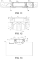
FIG. 11 is a schematic top view of the first end plate and the output terminal base inFIG. 8 fitted together. -
FIG. 12 is a schematic local cross-sectional view taken alone A-A inFIG. 11 . -
FIG. 13 is a schematic front view of the first end plate and the output terminal base inFIG. 8 fitted together. -
FIG. 14 is a schematic local cross-sectional view of a structure taken alone B-B inFIG. 13 . -
FIG. 15 is a schematic structural view of a battery pack according to an embodiment of the disclosure. -
battery module 100, frame 10,cell 20,output terminal base 30,side plate 11,first end plate 12,second end plate 13, high-voltage outputterminal installation portion 31, high-voltage output sheet 311, threadedhole 312, low-voltage outputterminal installation portion 32, limitingportion 33, limitinggroove 121,installation groove 122, first limitingportion 331, second limitingportion 332, third limitingportion 333, first limitinggroove 1211, second limitinggroove 1212, third limitinggroove 1213,first protrusion 3301, weight-reducinghole 1201,first side wall 1202,second side wall 1203,cell terminal 201, low-voltage connector 202,hook structure 321, reinforcingplate 34,second protrusion 341, andbox body 200. - The implementation of the disclosure is illustrated below by specific embodiments. A person having ordinary skill in the art can easily understand other advantages and effects of the disclosure from the content disclosed in this specification. The disclosure can also be implemented or applied through other different specific implementation ways. The details in this specification can also be modified or changed based on different viewpoints and applications without departing from the spirit of the disclosure.
- It should be noted that the drawings provided in the embodiments are merely schematically illustrating the basic idea of the disclosure. Therefore, the drawings only show components related to the disclosure rather than drawings which are depicted according to the numbers, shapes, and sizes of the components in actual implementation. In actual implementation, the types, numbers, and proportions of the components can be changed arbitrarily, and the component layout type may also be more complex.
- With reference to
FIG. 1 to FIG. 15 , in this embodiment, the disclosure provides a battery module and a battery pack to address the problem of unreliable fixing between a high-voltage output terminal and an FPC low-voltage connector found in the currently-available installation method for an output terminal base. To be specific, abattery module 100 includes a frame 10, a plurality ofcells 20, and anoutput terminal base 30. Herein, the frame 10 includesside plates 11 opposite to each other and a group of end plates opposite to each other. The end plates include afirst end plate 12 and asecond end plate 13. Theside plates 11, thefirst end plate 12, and thesecond end plate 13 are fixedly connected in sequence to form the frame 10. The plurality ofcells 20 are stacked in sequence, installed in the frame 10 after being stacked in sequence, and fixed by the pressing effect of theside plates 11 and the end plates. Theoutput terminal base 30 is fixedly installed on thefirst end plate 12 of the frame 10. - With reference to
FIG. 1 to FIG. 8 , in this embodiment, theoutput terminal base 30 includes a high-voltage outputterminal installation portion 31, a low-voltage outputterminal installation portion 32, and a limitingportion 33. Herein, the high-voltage outputterminal installation portion 31 is configured to allow a high-voltage output sheet 311 to be installed, so as to output the electric energy of thebattery module 100 to an electrical apparatus for powering the electrical apparatus. The low-voltage outputterminal installation portion 32 is configured to allow a low-voltage connector to be installed, so as to output low-voltage information such as electrical signals and temperature signals of the plurality ofcells 20 collected by a sampling assembly. To be specific, the high-voltage outputterminal installation portion 31 and the low-voltage outputterminal installation portion 32 are arranged side by side, and the limitingportion 33 is formed by extending from a bottom portion of the low-voltage outputterminal installation portion 32. For instance, the limitingportion 33 is formed by extending downwards from the bottom portion of the low-voltage outputterminal installation portion 32. That is, the high-voltage outputterminal installation portion 31 and the low-voltage outputterminal installation portion 32 are integrated on theoutput terminal base 30 and are fixedly installed with thefirst end plate 12 through the limitingportion 33. In this way, a simple structure and high integration are provided, and compatibility with a cells contact system assembly is achieved. To be specific, a top portion of thefirst end plate 12 is provided with a limitinggroove 121 and aninstallation groove 122. The high-voltage outputterminal installation portion 31 is installed in theinstallation groove 122, and the limitingportion 33 is installed in the limitinggroove 121 to fixedly install theoutput terminal base 30 onto thefirst end plate 12. That is, by integrating the high-voltage outputterminal installation portion 31 and the low-voltage outputterminal installation portion 32, a simple structure and high integration are provided. It should be noted that theoutput terminal base 30 is a plastic member for insulation and protection, and improved safety is thus provided. - With reference to
FIG. 1 andFIG. 7 toFIG. 9 , in this embodiment, a threadedhole 312 is arranged in the high-voltage outputterminal installation portion 31, and correspondingly, an through hole corresponding to the threadedhole 312 is arranged on the high-voltage output sheet 311. A fastening bolt is allowed to pass through the through hole on the high-voltage output sheet 311 and to be connected to the threadedhole 312, so that the high-voltage output sheet 311 is fixed in the high-voltage outputterminal installation portion 31. In some embodiments, when two ormore battery modules 100 are connected to each other, twoadjacent battery modules 100 are electrically connected to each other through a copper bar. Both ends of the copper bar are electrically connected to the high-voltage output sheets311 of the twobattery modules 100. That is, ends of the copper bar connected to the high-voltage output sheet 311are also installed in the relative high-voltage outputterminal installation portion 31. To be specific, an end portion of the copper bar is provided with a through hole as well, and the through hole corresponds to the through hole on the high-voltage output sheet 311 and the threadedhole 312. The fastening bolt is allowed to pass through the through hole on copper bar and the through hole on the high-voltage output sheet 311 and to be connected to the threadedhole 312, so that the copper bar and the high-voltage output sheet 311 are fixedly installed in the high-voltage outputterminal installation portion 31. - With reference to
FIG. 9 to FIG. 14 , in this embodiment, the limitingportion 33 includes a first limitingportion 331, a second limitingportion 332, and a third limitingportion 333. The first limitingportion 331 and the second limitingportion 332 are formed by extending away from a vertical direction. The third limitingportion 333 is located between the first limitingportion 331 and the second limitingportion 332, and the third limitingportion 333 is arranged in the vertical direction. That is, the first limitingportion 331 and the second limitingportion 332 are located on two sides of the third limitingportion 333 and are formed by deviating and extending in a direction away from the third limitingportion 333. Through the fixed connection between the plurality of limiting portions and thefirst end plate 12, the limiting effect is improved, and the reliability of the fixed connection between the limiting portions and thefirst end plate 12 is ensured. - With reference to
FIG. 9 to FIG. 14 , in this embodiment, the limitinggroove 121 includes a first limitinggroove 1211, a second limitinggroove 1212, and a third limiting groove 1213respectively corresponding to the first limitingportion 331, the second limitingportion 332, and the third limitingportion 333. The first limitingportion 331, the second limitingportion 332, and the third limitingportion 333 are respectively installed in the first limitinggroove 1211, the second limitinggroove 1212, and the third limitinggroove 1213 in a thickness direction of thefirst end plate 12 to fix theoutput terminal base 30 onto thefirst end plate 12. In this way, it is difficult for the limitingportion 33 on the bottom portion of theoutput terminal base 30 to be detached from the limitinggroove 121 on thefirst end plate 12, and thus the limiting effect between theoutput terminal base 30 and thefirst end plate 12 is enhanced. - With reference to
FIG. 9 to FIG. 14 , in this embodiment, at least one of the first limitingportion 331 and the second limitingportion 332 is provided with a sub-limiting portion, . The corresponding limiting groove on thefirst end plate 12 is provided with a sub-limiting groove, and the sub-limiting portion is connected to the sub-limiting groove in a concave-convex manner to form a limiting structure. For instance, the sub-limiting portion may be formed as afirst protrusion 3301, andfirst protrusions 3301 are provided on facing sides of both the first limitingportion 331 and the second limitingportion 332. When theoutput terminal base 30 is installed on thefirst end plate 12 in the thickness direction of thefirst end plate 12, thefirst protrusion 3301 is located in the limitinggroove 121 and forms a limiting structure with an inner wall of thefirst end plate 12. To be specific, in this embodiment, each of thefirst end plate 12 and the second end plate is provided with a plurality of weight-reducingholes 1201. The weight-reducingholes 1201 pass through the limitinggroove 121 or theinstallation groove 122 to reduce weights of the end plates. That is, in this embodiment, a plurality of cavity structures are arranged in thefirst end plate 12, and thefirst end plate 12 includes afirst side wall 1202 in contact with thecells 20 and asecond side wall 1203 away from thecells 20. When theoutput terminal base 30 is installed on thefirst end plate 12 in the thickness direction of thefirst end plate 12, thefirst protrusions 3301 are located in the cavities in thefirst end plate 12 to interfere with thefirst side wall 1202 to form a limiting structure. In this way, the limiting effect between theoutput terminal base 30 and thefirst end plate 12 is further improved, and theoutput terminal base 30 is further limited. - With reference to
FIG. 9 to FIG. 14 , in this embodiment, the limitinggroove 121 is formed by extending from an inner side to an outer side of thefirst end plate 12 in the thickness direction of thefirst end plate 12. Herein, the side of thefirst end plate 12 close to thecells 20 is the inner side, and the side away from thecells 20 is the outer side. An outer side wall of thefirst end plate 12 closes an end surface of the limitinggroove 121. That is, the limitinggroove 121 passes through thefirst side wall 1202 in the thickness direction of thefirst end plate 12 and does not stop extending until reaching thesecond side wall 1203 in the thickness direction. As such, thesecond side wall 1203 closes the end surface of the limitinggroove 121, so that the limitingpart 33 may only be installed into the limitinggroove 121 from the inner side of thefirst end plate 12 in its thickness direction. The movement of theoutput terminal base 30 in the thickness direction of thefirst end plate 12 is restricted under the fitting between thefirst protrusions 3301 and thesecond side wall 1203, so that theoutput terminal base 30 is better fixed. - In another embodiment, the limiting
portion 33 may further be formed as a plurality of elastic members, and the elastic members are engaged in the limiting groove. Through the elastic action of the elastic members, an interference fit is generated between the elastic members and the limiting groove, so that theoutput terminal base 30 is fixed on thefirst end plate 12. - With reference to
FIG. 9 to FIG. 14 , in this embodiment, the plurality ofcells 20 in thebattery module 100 are connected ontocell terminals 201 of thecells 20 through a connection sheet, so as to electrically connect thecells 20 to one another. Further, the high-voltage output sheet 311 is installed in the high-voltage outputterminal installation portion 31, and the high-voltage output sheet 311 is electrically connected to the connection sheet to achieve high-voltage output. In addition, thebattery module 100 further includes an FPC assembly. The FPC assembly is welded and connected to the connection sheet connectingdifferent cells 20 in thebattery module 100 through a sampling terminal, so as to collect low-voltage information such as electrical signals and temperature signals of the plurality ofcells 20. In some other embodiments, thebattery module 100 further includes a cells contact system assembly, and the cells contact system assembly is electrically connected to the plurality ofcells 20. The cells contact system assembly includes a sampling assembly and a high-voltage output sheet. Herein, the sampling assembly includes a flexible circuit board (not shown) and a low-voltage connector 202. The flexible circuit board is electrically connected to thecells 20. The low-voltage connector 202 is installed on the low-voltage outputterminal installation portion 32 and is electrically connected to the flexible circuit board, so as to output low-voltage information such as electrical signals and temperature signals of the plurality ofcells 20 collected by the sampling assembly. The high-voltage output sheet 311 is installed in the high-voltage outputterminal installation portion 31 and is electrically connected to thecells 20, so as to output the electric energy of thebattery module 100 to the electrical apparatus for powering the electrical apparatus. Herein, compared with the structure that uses a separate FPC assembly and connecting piece to connect the cells to achieve sampling, the cells contact system assembly is easier to install, so the installation efficiency and the grouping efficiency of the battery module may thus be improved. - With reference to
FIG. 9 to FIG. 14 , in this embodiment, the low-voltage outputterminal installation portion 32 further includeshook structures 321. Thehook structures 321 are formed by extending from both sides of a top portion of the low-voltage outputterminal installation portion 32 in a direction away from the low-voltage outputterminal installation portion 32. Theoutput terminal base 30 is further provided with a reinforcingplate 34. The reinforcingplate 34 is installed on the low-voltage outputterminal installation portion 32 and is located above the low-voltage connector 202. Both ends of the reinforcingplate 34 are engaged with and connected to thehook structures 321, andsecond protrusions 341 are formed on both ends of the reinforcingplate 34. When the reinforcingplate 34 is installed on the low-voltage outputterminal installation portion 32, thesecond protrusion 341 at each end is located between thehook structures 321 on a same side of the low-voltage outputterminal installation portion 32. In this way, the reinforcingplate 34 is fixed onto the low-voltage outputterminal installation portion 32, so that the low-voltage connector 202 is fixed, and the structural strength is enhanced. - With reference to
FIG. 1 to FIG. 15 , the disclosure further provides a battery pack. The battery pack includes abox body 200, and thebox body 200 is provided with at least onebattery module 100. The structure of thebattery module 100 is similar or identical to that of thebattery module 100 described in the abovementioned embodiments, and description thereof is thus not repeated herein to avoid repetition. - The disclosure provides a battery module and a battery pack. In the battery module, after the output terminal base is installed on the end plate, the inner surface of the end plate is close to the main bodies of the cells, it is thus difficult for the limiting portion on the bottom portion of the output terminal base to be detached from the limiting groove on the end plate, and a good limiting effect is thereby provided. Further, the high-voltage output terminal installation portion and the low-voltage output terminal installation portion are integrated on the output terminal base. In this way, a simple structure and high integration are provided, and compatibility with the cells contact system assembly is achieved. Further, the limiting groove on the end plate may also be used as a weight-reducing hole on the end plate.
Claims (13)
- A battery module (100), comprising:a frame (10) comprising side plates (11) opposite to each other and a first end plate (12) and a second end plate (13) opposite to each other;a plurality of cells (20) stacked and installed in the frame (10); andan output terminal base (30) comprising a high-voltage output terminal installation portion (31), a low-voltage output terminal installation portion (32), and a limiting portion (33), wherein the high-voltage output terminal installation portion (31) and the low-voltage output terminal installation portion (32) are arranged side by side, and the limiting portion (33) is formed by extending from a bottom portion of the low-voltage output terminal installation portion (32),wherein a top portion of the first end plate (12) is provided with a limiting groove (121) and an installation groove (122), the high-voltage output terminal installation portion (31) is installed in the installation groove (122), and the limiting portion (33) is installed in the limiting groove (121) to connect the output terminal base (30) to the first end plate (12).
- The battery module (100) according to claim 1, wherein the battery module (100) further comprises a cells contact system assembly, the cells contact system assembly is electrically connected to the cells (20), the cells contact system assembly comprises a sampling assembly and a high-voltage output sheet (311), the sampling assembly comprises a flexible circuit board and a low-voltage connector (202), the flexible circuit board is electrically connected to the cells (20), the low-voltage connector (202) is installed on the low-voltage output terminal installation portion (32) and is electrically connected to the flexible circuit board, and the high-voltage output sheet (311) is installed in the high-voltage output terminal installation portion (31) and is electrically connected to the cells (20).
- The battery module (100) according to claim 1 or claim 2, wherein a threaded hole (312) is arranged in the high-voltage output terminal installation portion (31), the high-voltage output sheet (311) is installed on the high-voltage output terminal installation portion (31), and a through hole corresponding to the threaded hole (312) is arranged on the high-voltage output sheet (311).
- The battery module (100) according to any one of claims 1 to 3, wherein the first end plate (12) or the second end plate (13) is provided with a plurality of weight-reducing holes (1201), and the weight-reducing holes (1201) pass through the limiting groove (121) or the installation groove (122).
- The battery module (100) according to any one of claims 1 to 4, wherein the low-voltage output terminal installation portion (32) further comprises hook structures (321), and the hook structures (321) are formed by extending from both sides of a top portion of the low-voltage output terminal installation portion (32) in a direction away from the low-voltage output terminal installation portion (32).
- The battery module (100) according to any one of claims 1 to 5, wherein the battery module (100) further comprises a reinforcing plate (34), the reinforcing plate (34) is installed on the low-voltage output terminal installation portion (32) and is located above the low-voltage connector (202), and both ends of the reinforcing plate (34) are engaged with and connected to the hook structures (321).
- The battery module (100) according to any one of claims 1 to 6, wherein protrusions are formed on both ends of the reinforcing plate (34), and the protrusion at each end is located between the hook structures (321) on a same side of the low-voltage output terminal installation portion (32).
- The battery module (100) according to any one of claims 1 to 7, wherein the limiting groove (121) is formed by extending from an inner side to an outer side of the first end plate (12) in a thickness direction of the first end plate (12), and an outer side wall of the first end plate (12) closes an end surface of the limiting groove (121).
- The battery module (100) according to any one of claims 1 to 8, wherein the limiting portion (33) comprises a first limiting portion (331), a second limiting portion (332), and a third limiting portion (333), the first limiting portion (331) and the second limiting portion (332) are formed by extending away from a vertical direction, the third limiting portion (333) is located between the first limiting portion (331) and the second limiting portion (332) and is arranged in the vertical direction, the limiting groove (121) comprises a first limiting groove (1211), a second limiting groove (1212), and a third limiting groove (1213) respectively corresponding to the first limiting portion (331), the second limiting portion (332), and the third limiting portion (333), and the first limiting portion (331), the second limiting portion (332), and the third limiting portion (333) are respectively installed in the first limiting groove (1211), the second limiting groove (1212), and the third limiting groove (1213) in a thickness direction of the first end plate (12) to fix the output terminal base (30).
- The battery module (100) according to any one of claims 1 to 9, wherein at least one of the first limiting portion (331) and the second limiting portion (332) is provided with a sub-limiting portion, the limiting groove (121) is provided with a sub-limiting groove, and the sub-limiting portion is connected to the sub-limiting groove in a concave-convex manner.
- The battery module (100) according to any one of claims 1 to 10, wherein the limiting portion (33) comprises a plurality of elastic members, and the elastic members are engaged in the limiting groove (121).
- The battery module (100) according to any one of claim 1 to 11, wherein the output terminal base (30) is a plastic member.
- A battery pack comprising a box body (200), wherein the battery module (100) according to any one of claims 1 to 12 is installed in the box body (200).
Applications Claiming Priority (1)
| Application Number | Priority Date | Filing Date | Title |
|---|---|---|---|
| CN202320276490.2U CN219457865U (en) | 2023-02-21 | 2023-02-21 | Battery modules and battery packs |
Publications (1)
| Publication Number | Publication Date |
|---|---|
| EP4421954A1 true EP4421954A1 (en) | 2024-08-28 |
Family
ID=87411536
Family Applications (1)
| Application Number | Title | Priority Date | Filing Date |
|---|---|---|---|
| EP23197613.5A Pending EP4421954A1 (en) | 2023-02-21 | 2023-09-15 | Battery module and battery pack |
Country Status (4)
| Country | Link |
|---|---|
| US (1) | US20240283069A1 (en) |
| EP (1) | EP4421954A1 (en) |
| JP (1) | JP7681673B2 (en) |
| CN (1) | CN219457865U (en) |
Families Citing this family (1)
| Publication number | Priority date | Publication date | Assignee | Title |
|---|---|---|---|---|
| CN121172361A (en) * | 2025-11-20 | 2025-12-19 | 宁德时代新能源科技股份有限公司 | Battery device and electricity utilization device |
Citations (4)
| Publication number | Priority date | Publication date | Assignee | Title |
|---|---|---|---|---|
| CN206727133U (en) * | 2017-05-15 | 2017-12-08 | 宁德时代新能源科技股份有限公司 | Battery modules |
| EP3806178A1 (en) * | 2019-08-15 | 2021-04-14 | Contemporary Amperex Technology Co., Limited | Battery module |
| CN113036287A (en) * | 2021-03-04 | 2021-06-25 | 合肥国轩高科动力能源有限公司 | Laminate polymer battery module |
| US20220094012A1 (en) * | 2019-06-03 | 2022-03-24 | Contemporary Amperex Technology Co., Limited | Terminal protection device and battery module |
Family Cites Families (5)
| Publication number | Priority date | Publication date | Assignee | Title |
|---|---|---|---|---|
| KR101636380B1 (en) | 2013-09-26 | 2016-07-05 | 주식회사 엘지화학 | Voltage Sensing Assembly and Battery Module Including the Same |
| CN207896173U (en) | 2018-03-23 | 2018-09-21 | 宁德时代新能源科技股份有限公司 | Battery modules |
| JP7214968B2 (en) | 2018-03-23 | 2023-01-31 | 株式会社Gsユアサ | power storage device |
| CN112531299B (en) | 2020-11-27 | 2023-02-24 | 宁德时代新能源科技股份有限公司 | Mounting seat, battery and electrical equipment |
| CN214589171U (en) | 2021-04-09 | 2021-11-02 | 宁德时代新能源科技股份有限公司 | Battery and power consumption device |
-
2023
- 2023-02-21 CN CN202320276490.2U patent/CN219457865U/en active Active
- 2023-08-23 US US18/454,070 patent/US20240283069A1/en active Pending
- 2023-09-15 EP EP23197613.5A patent/EP4421954A1/en active Pending
- 2023-12-12 JP JP2023209716A patent/JP7681673B2/en active Active
Patent Citations (4)
| Publication number | Priority date | Publication date | Assignee | Title |
|---|---|---|---|---|
| CN206727133U (en) * | 2017-05-15 | 2017-12-08 | 宁德时代新能源科技股份有限公司 | Battery modules |
| US20220094012A1 (en) * | 2019-06-03 | 2022-03-24 | Contemporary Amperex Technology Co., Limited | Terminal protection device and battery module |
| EP3806178A1 (en) * | 2019-08-15 | 2021-04-14 | Contemporary Amperex Technology Co., Limited | Battery module |
| CN113036287A (en) * | 2021-03-04 | 2021-06-25 | 合肥国轩高科动力能源有限公司 | Laminate polymer battery module |
Also Published As
| Publication number | Publication date |
|---|---|
| JP2024119026A (en) | 2024-09-02 |
| JP7681673B2 (en) | 2025-05-22 |
| US20240283069A1 (en) | 2024-08-22 |
| CN219457865U (en) | 2023-08-01 |
Similar Documents
| Publication | Publication Date | Title |
|---|---|---|
| TWI504045B (en) | Battery module and battery pack including the same | |
| US8632905B2 (en) | Battery module and battery pack | |
| EP2752918B1 (en) | Battery module assembly having improved reliability and medium or large-sized battery pack including same | |
| CN212062595U (en) | A fuel cell inspection system | |
| WO2020056858A1 (en) | Energy system for new energy vehicle | |
| CN111430650A (en) | Battery packs and vehicles | |
| CN213150824U (en) | Copper bar sealing connector, high voltage module of fuel cell system and fuel cell system | |
| CN207353365U (en) | An integrated BUSBAR busbar used in a battery module | |
| JP2015082398A (en) | Battery pack unit | |
| JP2019525441A (en) | Modular power storage and supply system | |
| US20240283069A1 (en) | Battery module and battery pack | |
| KR101928066B1 (en) | Connecting structure of bus-bar assembly | |
| CN114678225B (en) | Super capacitor module, assembling method thereof, energy storage power supply and locomotive | |
| CN214227086U (en) | Sampling assembly and battery module | |
| US20210344089A1 (en) | Protection assembly of battery module and battery module | |
| CN222581410U (en) | Battery pack and vehicle | |
| JP6452402B2 (en) | Power storage device | |
| CN207021329U (en) | A kind of electrokinetic cell and its electric connection component | |
| CN216311952U (en) | Lithium battery module assembly structure | |
| CN116031551A (en) | Module panel, battery module and battery pack | |
| CN210723240U (en) | Fuel cell system and vehicle | |
| CN110828764B (en) | Battery package circuit breaker, battery package and new energy automobile | |
| CN219696737U (en) | Servo connector with power terminal and brake terminal | |
| CN219246859U (en) | Battery modules and packs | |
| CN223927699U (en) | High-current copper busbar connectors for photovoltaic inverters |
Legal Events
| Date | Code | Title | Description |
|---|---|---|---|
| PUAI | Public reference made under article 153(3) epc to a published international application that has entered the european phase |
Free format text: ORIGINAL CODE: 0009012 |
|
| STAA | Information on the status of an ep patent application or granted ep patent |
Free format text: STATUS: REQUEST FOR EXAMINATION WAS MADE |
|
| 17P | Request for examination filed |
Effective date: 20230915 |
|
| AK | Designated contracting states |
Kind code of ref document: A1 Designated state(s): AL AT BE BG CH CY CZ DE DK EE ES FI FR GB GR HR HU IE IS IT LI LT LU LV MC ME MK MT NL NO PL PT RO RS SE SI SK SM TR |
|
| RBV | Designated contracting states (corrected) |
Designated state(s): AL AT BE BG CH CY CZ DE DK EE ES FI FR GB GR HR HU IE IS IT LI LT LU LV MC ME MK MT NL NO PL PT RO RS SE SI SK SM TR |
|
| STAA | Information on the status of an ep patent application or granted ep patent |
Free format text: STATUS: EXAMINATION IS IN PROGRESS |
|
| 17Q | First examination report despatched |
Effective date: 20250115 |