EP4421950A1 - Battery pack - Google Patents
Battery pack Download PDFInfo
- Publication number
- EP4421950A1 EP4421950A1 EP23831937.0A EP23831937A EP4421950A1 EP 4421950 A1 EP4421950 A1 EP 4421950A1 EP 23831937 A EP23831937 A EP 23831937A EP 4421950 A1 EP4421950 A1 EP 4421950A1
- Authority
- EP
- European Patent Office
- Prior art keywords
- base plate
- battery pack
- space
- inlet
- flow path
- Prior art date
- Legal status (The legal status is an assumption and is not a legal conclusion. Google has not performed a legal analysis and makes no representation as to the accuracy of the status listed.)
- Granted
Links
Images


Classifications
-
- H—ELECTRICITY
- H01—ELECTRIC ELEMENTS
- H01M—PROCESSES OR MEANS, e.g. BATTERIES, FOR THE DIRECT CONVERSION OF CHEMICAL ENERGY INTO ELECTRICAL ENERGY
- H01M50/00—Constructional details or processes of manufacture of the non-active parts of electrochemical cells other than fuel cells, e.g. hybrid cells
- H01M50/20—Mountings; Secondary casings or frames; Racks, modules or packs; Suspension devices; Shock absorbers; Transport or carrying devices; Holders
- H01M50/249—Mountings; Secondary casings or frames; Racks, modules or packs; Suspension devices; Shock absorbers; Transport or carrying devices; Holders specially adapted for aircraft or vehicles, e.g. cars or trains
-
- H—ELECTRICITY
- H01—ELECTRIC ELEMENTS
- H01M—PROCESSES OR MEANS, e.g. BATTERIES, FOR THE DIRECT CONVERSION OF CHEMICAL ENERGY INTO ELECTRICAL ENERGY
- H01M10/00—Secondary cells; Manufacture thereof
- H01M10/60—Heating or cooling; Temperature control
- H01M10/65—Means for temperature control structurally associated with the cells
- H01M10/656—Means for temperature control structurally associated with the cells characterised by the type of heat-exchange fluid
- H01M10/6567—Liquids
- H01M10/6568—Liquids characterised by flow circuits, e.g. loops, located externally to the cells or cell casings
-
- H—ELECTRICITY
- H01—ELECTRIC ELEMENTS
- H01M—PROCESSES OR MEANS, e.g. BATTERIES, FOR THE DIRECT CONVERSION OF CHEMICAL ENERGY INTO ELECTRICAL ENERGY
- H01M10/00—Secondary cells; Manufacture thereof
- H01M10/60—Heating or cooling; Temperature control
- H01M10/61—Types of temperature control
- H01M10/613—Cooling or keeping cold
-
- H—ELECTRICITY
- H01—ELECTRIC ELEMENTS
- H01M—PROCESSES OR MEANS, e.g. BATTERIES, FOR THE DIRECT CONVERSION OF CHEMICAL ENERGY INTO ELECTRICAL ENERGY
- H01M10/00—Secondary cells; Manufacture thereof
- H01M10/60—Heating or cooling; Temperature control
- H01M10/62—Heating or cooling; Temperature control specially adapted for specific applications
- H01M10/625—Vehicles
-
- H—ELECTRICITY
- H01—ELECTRIC ELEMENTS
- H01M—PROCESSES OR MEANS, e.g. BATTERIES, FOR THE DIRECT CONVERSION OF CHEMICAL ENERGY INTO ELECTRICAL ENERGY
- H01M10/00—Secondary cells; Manufacture thereof
- H01M10/60—Heating or cooling; Temperature control
- H01M10/65—Means for temperature control structurally associated with the cells
- H01M10/655—Solid structures for heat exchange or heat conduction
- H01M10/6556—Solid parts with flow channel passages or pipes for heat exchange
-
- H—ELECTRICITY
- H01—ELECTRIC ELEMENTS
- H01M—PROCESSES OR MEANS, e.g. BATTERIES, FOR THE DIRECT CONVERSION OF CHEMICAL ENERGY INTO ELECTRICAL ENERGY
- H01M50/00—Constructional details or processes of manufacture of the non-active parts of electrochemical cells other than fuel cells, e.g. hybrid cells
- H01M50/20—Mountings; Secondary casings or frames; Racks, modules or packs; Suspension devices; Shock absorbers; Transport or carrying devices; Holders
- H01M50/204—Racks, modules or packs for multiple batteries or multiple cells
- H01M50/207—Racks, modules or packs for multiple batteries or multiple cells characterised by their shape
- H01M50/209—Racks, modules or packs for multiple batteries or multiple cells characterised by their shape adapted for prismatic or rectangular cells
-
- H—ELECTRICITY
- H01—ELECTRIC ELEMENTS
- H01M—PROCESSES OR MEANS, e.g. BATTERIES, FOR THE DIRECT CONVERSION OF CHEMICAL ENERGY INTO ELECTRICAL ENERGY
- H01M50/00—Constructional details or processes of manufacture of the non-active parts of electrochemical cells other than fuel cells, e.g. hybrid cells
- H01M50/20—Mountings; Secondary casings or frames; Racks, modules or packs; Suspension devices; Shock absorbers; Transport or carrying devices; Holders
- H01M50/233—Mountings; Secondary casings or frames; Racks, modules or packs; Suspension devices; Shock absorbers; Transport or carrying devices; Holders characterised by physical properties of casings or racks, e.g. dimensions
-
- H—ELECTRICITY
- H01—ELECTRIC ELEMENTS
- H01M—PROCESSES OR MEANS, e.g. BATTERIES, FOR THE DIRECT CONVERSION OF CHEMICAL ENERGY INTO ELECTRICAL ENERGY
- H01M50/00—Constructional details or processes of manufacture of the non-active parts of electrochemical cells other than fuel cells, e.g. hybrid cells
- H01M50/20—Mountings; Secondary casings or frames; Racks, modules or packs; Suspension devices; Shock absorbers; Transport or carrying devices; Holders
- H01M50/271—Lids or covers for the racks or secondary casings
-
- H—ELECTRICITY
- H01—ELECTRIC ELEMENTS
- H01M—PROCESSES OR MEANS, e.g. BATTERIES, FOR THE DIRECT CONVERSION OF CHEMICAL ENERGY INTO ELECTRICAL ENERGY
- H01M2220/00—Batteries for particular applications
- H01M2220/20—Batteries in motive systems, e.g. vehicle, ship, plane
-
- Y—GENERAL TAGGING OF NEW TECHNOLOGICAL DEVELOPMENTS; GENERAL TAGGING OF CROSS-SECTIONAL TECHNOLOGIES SPANNING OVER SEVERAL SECTIONS OF THE IPC; TECHNICAL SUBJECTS COVERED BY FORMER USPC CROSS-REFERENCE ART COLLECTIONS [XRACs] AND DIGESTS
- Y02—TECHNOLOGIES OR APPLICATIONS FOR MITIGATION OR ADAPTATION AGAINST CLIMATE CHANGE
- Y02E—REDUCTION OF GREENHOUSE GAS [GHG] EMISSIONS, RELATED TO ENERGY GENERATION, TRANSMISSION OR DISTRIBUTION
- Y02E60/00—Enabling technologies; Technologies with a potential or indirect contribution to GHG emissions mitigation
- Y02E60/10—Energy storage using batteries
Definitions
- the present invention relates to a battery pack, and more specifically, the battery pack of the present invention provides a pack case having a structure of maximizing the cooling efficiency of accommodated battery module using coolant that flows inside.
- An operating voltage of the unit secondary battery cell is about 2.5V to 4.2V. Therefore, if a higher output voltage is required, a plurality of battery cells may be connected in series to configure a battery pack. In addition, depending on the charge/discharge capacity required for the battery pack, a plurality of battery cells may be connected in parallel to configure a battery pack. Thus, the number of battery cells included in the battery pack may be variously set according to the required output voltage or the charge/discharge capacity.
- a battery module composed of a plurality of battery cells first.
- a conventional battery pack comprises a pack case in which battery modules are accommodated, and a top cover coupled to the pack case to cover the battery modules accommodated in the pack case.
- the pack case may be formed with an inner space surrounded by side walls, and a plurality of battery modules are separately accommodated in a section formed by a plurality of separation walls.
- the battery modules included in a large capacity battery pack such as the above may have performance largely determined according to temperature, and the temperature of each of the battery modules may increase during charging and discharging.
- the battery pack may include a plurality of battery modules, and the plurality of battery modules may preferably be managed so that the temperature difference among them is minimized.
- the electric vehicle may be equipped with a battery cooling device that cools each of the battery modules accommodated in the battery pack to prevent overheating of these battery modules and thereby maintain the performance of the battery modules.
- a representative battery cooling device is a water-cooled battery cooling device.
- the water-cooled cooling device operates on the principle of cooling each battery module by supplying water cooled to a low temperature to the battery pack in which the battery modules are accommodated.
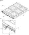
- FIG. 1 is a perspective view of a battery pack applied to an electric vehicle with a water-cooled cooling device
- FIG. 2 is a front view of the battery pack of FIG. 1 . Since each battery module included in the battery pack, as shown in FIGS. 1 and 2 , is accommodated in a nearly enclosed space by the top cover 10 covering the top of the battery pack and the side walls 30 covering the sides the battery pack operates in an environment that is highly vulnerable to heating.
- the base plate 20 which corresponds to the lower part of the battery pack, has a plurality of tube-shaped flow paths 80 installed therein, and the low-temperature coolant injected through the inlet 40 is divided into a plurality of hoses 70 connected to the inlet 40, and then moves to each flow path 80 through the auxiliary inlet 60 connected to the hoses 70.
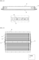
- FIG. 3 is a brief diagram of the path Ct that coolant flows through the flow paths 80 in the battery pack of FIG. 1 .
- coolant is introduced into each of the auxiliary inlets 60 and flows in one direction through the channels 80 associated with the auxiliary inlets 60 to cool the battery modules accommodated in the battery pack, and is discharged through the outlet 50.
- a battery pack having the above structure has the disadvantage of complicated assembly, requiring a process of connecting inlets, outlets, hoses, auxiliary inlets, and flow channels.
- the cross-section of the flow channel is a round shape, and there is a disadvantage that the area in contact with the battery module actually accommodated in the battery pack is less, thereby not performing effective cooling.
- the present invention was conceived to solve the above problems, and aims to provide a battery pack having a structure capable of effectively cooling a battery module accommodated therein.
- a battery pack for accommodating battery modules including a pack case that includes a module area in which the battery modules are mounted, and the pack case including a base plate in the form of a hollow shape to support a lower part of a battery module and having a plurality of space parts formed therein for storing coolant; sidewalls coupled to a rim of the base plate; and a separation wall coupled to the base plate to separate the module area for mounting the battery modules; the separation wall comprising: a main separation wall extended and formed across the centered part of the pack case, wherein the base plate includes at both ends an inlet and an outlet through which coolant can flow in and out and communicated with the space part, respectively, wherein the base plate further includes a flow path part, and wherein the flow path part a plurality of cooling flow paths connecting the space parts to each other between a pair of adjacent space parts.
- the coolant injected into the inlet may be discharged through the space part and the cooling flow path to the outlet.
- the space parts may be formed separate at predetermined intervals along the length of the pack case.
- the base plate may include an injection part including a space part formed at a front end of the base plate and directly communicated with the injection part, a discharge part including a space part formed at a rear end of the base plate and directly communicated with the outlet, and a temperature exchange part including a plurality of space parts formed at locations corresponding to each module area.
- Each of the space parts included in the temperature exchange part may be formed corresponding to an area size of the module area.
- any one of the space parts included in the temperature exchange part may be communicated with respective cooling flow paths included in the flow path parts located at both ends of the space part, and the coolant flowing through the respective cooling flow paths of the flow path parts located at the front end of the space part may be joined in the space part, and the coolant joined in the space part may be dispersed and moved to the respective cooling flow paths of the flow path parts located at the rear end of the space part.
- Coolant injected into the space part of the injection part through the inlet may be dispersed and moved to the respective cooling flows of the flow path parts adjacent to the space part of the injection part, and coolant moved through the respective cooling flows of the flow path parts adjacent to the space part of the discharge part may be joined in the space part of the discharge part and discharged through the outlet.
- the space parts and flow path parts may be formed alternately along the length direction of the pack case.
- the pack case may further include a sub-separation wall, which is coupled at both ends to the main separation wall and side wall and coupled to the base plate to separate between a pair of adjacent battery modules; and the flow path parts may be included at locations corresponding to the sub-separation wall.
- the flow path parts may include a plurality of cooling flow paths, and the cooling flow paths included in the flow path parts may be arranged side by side along a width direction of the pack case.
- the base plate may include a pair of inlets at a front end and a pair of outlets at a rear end connected to each of the inlets.
- the inlet including a first inlet formed on one side of the main-separation wall wherein the first module area is located, and a second inlet formed on the other side of the main-separation wall wherein the second module area is located, and the outlet including a first outlet communicated with the first inlet on one side of the main-separation wall, and a second outlet communicated with the second inlet on the other side of the main-separation wall, wherein the first inlet may be positioned diagonally to the first outlet on one side of the main-separation wall, and the second inlet may be positioned diagonally to the second outlet on the other side of the main-separation wall.
- the base plate may has an open front and rear side, and include a cooling cover coupled to the open front and rear sides.
- the cooling cover may further include protrusions projecting forward, having a hollow shape, and the inlet and outlet may be installed in the protrusion parts of the cooling cover coupled to the front and rear sides of the pack case.
- a plurality of battery modules accommodated in a battery pack can be effectively cooled to prevent the battery pack from overheating and explosion.
- the present invention relates to a battery pack 1000 accommodating a battery module B. More specifically, the battery pack 1000 of the present invention is characterized in that it includes a pack case 200 capable of effectively cooling the accommodated battery module B.
- the pack case 200 is provided in the present invention.
- FIGS. 4 to 10 relate to a battery pack (1000) according to a first embodiment of the present invention
- FIGS. 11 to 13 relate to a battery pack (1000) according to a second embodiment of the present invention.
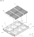
- FIG. 4 is a perspective view of a battery pack according to a first embodiment of the present invention.
- FIG. 5 is a modified embodiment of the battery pack shown in FIG. 4 .
- FIG. 6 is a front view of the battery pack of FIG. 4 .
- the battery pack 1000 of the present invention includes a pack case 200 and a top cover 100.
- the top cover 100 is coupled with the pack case 200 to cover the top of each battery module B accommodated in the pack case 200.
- top cover 100 corresponds to the known art, a detailed description thereof will be omitted herein.
- the pack case 200 includes a base plate 210, sidewall and separation wall 230, and provides a module area A in which a battery module B is mounted.
- the sidewalls are coupled along a rim of the base plate 210.
- the sidewalls include a front frame 221 coupled to the base plate 210 to cover the front of the base plate 210, a rear frame 222 coupled to the base plate 210 to cover the rear of the base plate 210, and side frames 223 coupled on both sides of the base plate 210 to cover the sides of the base plate 210.
- the battery pack (1000) according to a first embodiment of the present invention has a front end of the base plate (210) projecting toward the front of the front frame (221) and a rear end of the base plate (210) projecting toward the rear of the rear frame (222).
- the front frame 221 is coupled to the base plate 210 at a position predetermined spaced apart from the front end of the base plate 210 such that the front end of the base plate 210 can project forwardly of the front end of the front frame 221.
- the rear frame 222 is coupled with the base plate 210 at a predetermined spaced position from the rear end of the base plate 210 such that the rear end of the base plate 210 can project toward the front of the rear frame 222.
- the separation wall is coupled to the base plate 210 to separate a module area A in which each battery module B is mounted.
- the separation walls includes a main-separation wall 231 formed to extend across the center part of the pack case 200.
- the pack case 200 may be largely separated into two spaces by each of the main-separation wall 231, and a plurality of battery modules B may be mounted on the base plate 210 side by side along the main-separation wall 231 on both sides of the main-separation wall 231. At this time, the battery modules B accommodated on one side of the main-separation wall 231 may be further separated by the sub-separation wall 232.
- the pack case 200 may further include a sub-separation wall 232 that separates the space formed by the main-separation wall 231 in the length direction d1 of the pack case 200 to form a module area A in which the battery module B is mounted.
- the sub-separation wall 232 may be installed in the pack case 200 separately from the battery module B, but may be provided attached to the battery module B in another embodiment.
- FIG. 5 is a perspective view of the pack case 200 accommodating battery modules B with sub-separation wall 232 attached on both sides, wherein each battery module B is separated and supported by a sub-separation wall 232 attached to a side of the battery module B as the battery module B is mounted in each module area A.
- the base plate (210) is characterized in that it has a hollow shape, supports the lower part of the battery module (B), and includes inside a plurality of space parts (Cv) in which the coolant is stored.
- the base plate 210 is open at the front and rear sides, and includes a cooling cover 214 coupled to the front and rear sides to cover the open front and rear sides.
- FIG. 6(a) is a battery pack 1000 with the cooling cover 214 coupled
- FIG. 6(b) is a battery pack 1000 with the cooling cover 214 detached.
- the cooling cover 214 may be divided into a first cooling cover 214a coupled to the front side of the base plate 210 and a second cooling cover coupled to the rear side of the base plate 210.
- the inside of the base plate 210 is hollow, as shown in FIG. 6 , and a plurality of separation walls 213 are formed inside the hollow, which are built up in the direction of the thickness of the base plate 210.
- the cooling cover 214 is coupled with the base plate 210 so as to cover the open front and rear sides of the base plate 210. In this case, the cooling cover 214 may be separately detachable from the base plate 210 as shown or may be integrally manufactured with the base plate 210.
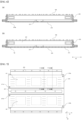
- FIG. 7 is a top view of a pack case of the present invention.
- FIG. 8 is an illustration of cooling flow paths and space parts inside the base plate corresponding to the first module area and the second module area in the pack case of FIG. 7 .
- FIG. 9 is a partial cross-sectional view of the pack case of FIG. 7 .
- FIG. 10 illustrates a movement path of the coolant through the cooling flow path and space parts of FIG. 8 .
- the first module area A1 and the second module area A2 are formed at predetermined intervals spaced apart along the length direction d1 of the pack case 200 on both sides of the main-separation wall 231, and each battery module B is mounted in the respective module area A.
- the battery pack 1000 of the present invention is characterized in that it effectively cools the battery modules B accommodated therein, the cooling being accomplished by allowing coolant to flow inside a base plate 210 included in the pack case 200.
- the present invention forms a plurality of space parts Cv inside the base plate 210 to maximize the cooling effect, and enables the coolant to exchange temperature with the battery module B through a large area of the space part Cv.
- the space part Cv is formed at predetermined intervals spaced apart along the length direction d1 of the pack case 200, same as the module area A.
- the base plate 210 of the present invention further includes an inlet 211, an outlet 212, and a flow path part P4 in addition to the space part Cv.
- the base plate 210 includes an inlet 211 and an outlet 212, respectively, at both ends. More specifically, the inlet 211 is installed at the front end of the base plate 210 protruding a predetermined length from the front frame 221, and the outlet 212 is installed at the rear end of the base plate 210 protruding a predetermined length from the rear frame 222.
- Coolant injected into the base plate 210 to cool the battery module B enters the inside of the base plate 210 through the inlets 211 and discharges to the outside through the outlet 212 connected to the inlet 211.
- the base plate 210 includes a pair of inlets 211 at a front end and a pair of outlets 212 at a rear end connected to each of the inlet 211.
- a pair of inlets 211 are separately located at the front end of the base plate 210 across the main-separation wall 231, and a pair of outlets 212 are separately located at the rear end of the base plate 210.
- the inlets 211 include a first inlet 211a formed on one side of the main-separation wall 231 where the first module area A1 is located and a second inlet 211b formed on the other side of the main-separation wall 231 where the second module area A2 is located.
- the outlet 212 includes a first outlet 212a formed on one side of the main-separation wall 231 where the first module area A1 is located and a second outlet 212b formed on the other side of the main-separation wall 231 where the second module area A2 is located.
- Each of the connected inlets 211 and outlets 212 is preferably positioned diagonally to each other on the base plate 210.
- first inlet 211a is installed in a diagonal direction with respect to the first outlet 212a on one side of the main-separation wall 231
- second inlet 211b is installed in a diagonal direction with respect to the second outlet 212b on the other side of the main-separation wall 231.
- the first inlet 211a and second inlet 211b are installed at a position adjacent to the main-separation wall 231 at the front end of the base plate 210, respectively and the first outlet 212a and second outlet 212b are installed at a position adjacent to the side frames 223 located on both sides of the base plate 210 at the rear end of the base plate 210, respectively.
- the flow path part P4 includes a plurality of cooling flow paths connecting the space parts Cv to be connected to each other between a pair of adjacent space parts Cv.
- the cooling flow paths are formed to extend along the length direction d1 of the pack case 200, and the plurality of cooling flow paths included in the flow path part P4 are arranged side by side along the width direction d2 of the pack case 200.
- the flow path part P4 is located between the space parts Cv separated at predetermined intervals along the length direction d1 of the pack case 200. Therefore, coolant can move from one of the space parts Cv to the other space part Cv through the cooling flow paths included in the flow path part P4.
- the coolant injected into the inlet 211 is discharged to the outlet 212 through the space part Cv and the cooling flow path.
- the flow path part P4 is formed corresponding to a location of a boundary point position between a pair of adjacent module areas A. More specifically, the flow path parts P4 are formed in a position corresponding to the sub-separation wall 232 installed at the boundary points of the module areas A.
- FIG. 9 a cross-sectional view cutting a position between a pair of module areas A in the pack case 200 of FIG. 7 and a cross-sectional view cutting the module areas A are shown, respectively.
- a plurality of separation walls 213 formed at predetermined intervals along the width direction d2 of the pack case 200 and a plurality of cooling flow paths formed between the separation walls 213 are formed.
- each cooling flow path included in the above one flow path part P4 is formed by a separation wall 213 formed to be spaced apart by a predetermined interval in the inner hollow of the base plate 210, that is, one cooling flow path is formed by an adjacent pair of separation walls 213.
- one space part Cv is formed between the side frame 223 and the main-separation wall 231.
- the space parts Cv are formed on each side of the base plate 210 based on the main-separation wall 231, and are formed corresponding to the positions of the module areas A along the length direction d1 of the pack case 200.
- the space part Cv and the flow path part P4 formed on one side of the main-separation wall 231 are formed alternately with each other along the length direction d1 of the pack case 200.
- the inside of the base plate 210 is divided into three main sections, that is, the base plate 210 includes an injection part P1, a discharge part P3, and a temperature exchange part P2.
- the injection part P1 includes a space part Cv formed at the front end of the base plate 210 and directly communicated with the inlet 211.
- the coolant flowed into the space part Cv of the injection part P1 through the inlet 211 is dispersed and moved to each cooling oil in the flow path part P4 adjacent to the space part Cv of the injection part P1, as shown in FIG. 10 .
- the discharge part P3 includes a space part Cv formed at the rear end of the base plate 210 and directly communicated with the outlet 212.
- the coolant that has moved through each coolant flow path of the flow path part P4 adjacent to the space part Cv of the discharge part P3 is joined at the space part Cv of the discharge part P3 and discharged through the outlet 212.
- the temperature exchange part P2 is located between the injection part P1 and the discharge part P3, and includes a plurality of space parts Cv formed at positions corresponding to the respective module areas A.
- each space part Cv included in the temperature exchange part P2 is formed for the purpose of cooling each battery module (B) installed in the corresponding module area (A) through the largest possible surface area, so it is preferably formed corresponding to the area size of the module area (A) or the size of the battery module (B) installed in the module area (A).
- At least one space part Cv included in the temperature exchange part P2 is communicated with each coolant flow path of the flow path part P4 located at the front and rear sides, respectively.
- each coolant flow path of the flow path part P4 located in front of the space part Cv is joined in the space part Cv.
- the joined coolant is dispersed to each coolant flow path of the flow path part P4 located at the rear of the space part Cv and moves to the next space part Cv.
- the battery pack 1000 according to the second embodiment of the present invention differs from the battery pack 1000 according to the first embodiment in the location where the inlet 211 and outlet 212 through which coolant flows in and out are installed.
- the battery pack 1000 has a front frame 221 and a rear frame 222 coupled to the base plate 210 and coupled to a front end and a rear end of the base plate 210, respectively.
- FIG. 11 is a perspective view of a battery pack 1000 according to a second embodiment of the present invention. Specifically, FIG. 11(a) shows a cooling cover 214 detached from a base plate 210, and FIG. 11(b) shows the cooling cover 214 coupled to the base plate 210.
- the base plate (210) included in the battery pack (1000) includes a cooling cover (214) that is open at the front and back and is coupled to cover the openings with the open front and back sides.
- the cooling cover 214 further includes a forwardly projecting protrusion part 215.
- the protrusion part 215 is molded with an inlet 211 or outlet 212 through which coolant flows in and out.
- the inlet 211 and the outlet 212 is connected to the inlet 211 are preferably located diagonally to each other on the base plate 210. Therefore, the protrusion part 215disposedin the cooling cover 214, which includes the inlet 211 and is located at the front end of the base plate 210and the protrusion parts 215disposedin the cooling cover 214, which includes the outlet 212 connected to the inlet 211, and is located at the rear end of the base plate 210, are positioned diagonally each other.
- a protrusion part 215 of the cooling cover 214 located at the front end of the base plate 210 is formed at one end of the two ends of the cooling cover 214 adjacent to the main-separation wall 231, and a protrusion part 215 of the cooling cover 214 opposite the cooling cover 214 and located at the rear end of the base plate 210 is formed at one end of the two ends of the cooling cover 214 adjacent to the side frame 223.
- FIG. 12 illustrates a portion of the cooling cover 214 including the protrusion part 215.
- the protrusion part 215 projecting from the cooling cover 214 is in the form of an inlet 211 formed at the top and a hollow interior. Further, the interior hollow is open to one side and the coolant introduced through the inlet 211 flows through one side of the open protrusion part 215 to the inside of the base plate 210 coupled to the cooling cover 214.
Landscapes
- Chemical & Material Sciences (AREA)
- Chemical Kinetics & Catalysis (AREA)
- Electrochemistry (AREA)
- General Chemical & Material Sciences (AREA)
- Engineering & Computer Science (AREA)
- Manufacturing & Machinery (AREA)
- Aviation & Aerospace Engineering (AREA)
- Secondary Cells (AREA)
- Battery Mounting, Suspending (AREA)
Abstract
Description
- The present invention relates to a battery pack, and more specifically, the battery pack of the present invention provides a pack case having a structure of maximizing the cooling efficiency of accommodated battery module using coolant that flows inside.
- This application claims the benefit of priority from
Korean Patent Application No. 10-2022-0081128, filed on July1, 2022 - An operating voltage of the unit secondary battery cell is about 2.5V to 4.2V. Therefore, if a higher output voltage is required, a plurality of battery cells may be connected in series to configure a battery pack. In addition, depending on the charge/discharge capacity required for the battery pack, a plurality of battery cells may be connected in parallel to configure a battery pack. Thus, the number of battery cells included in the battery pack may be variously set according to the required output voltage or the charge/discharge capacity.
- For example, when a plurality of battery cells is connected in series or in parallel to configure a battery pack, it is common to configure a battery module composed of a plurality of battery cells first.
- A conventional battery pack comprises a pack case in which battery modules are accommodated, and a top cover coupled to the pack case to cover the battery modules accommodated in the pack case.
- The pack case may be formed with an inner space surrounded by side walls, and a plurality of battery modules are separately accommodated in a section formed by a plurality of separation walls.
- Recently, the demand for large-capacity battery packs applied to electric vehicles, etc. has been increasing.
- The battery modules included in a large capacity battery pack such as the above may have performance largely determined according to temperature, and the temperature of each of the battery modules may increase during charging and discharging. In other words, the battery pack may include a plurality of battery modules, and the plurality of battery modules may preferably be managed so that the temperature difference among them is minimized.
- The electric vehicle may be equipped with a battery cooling device that cools each of the battery modules accommodated in the battery pack to prevent overheating of these battery modules and thereby maintain the performance of the battery modules.
- A representative battery cooling device is a water-cooled battery cooling device. The water-cooled cooling device operates on the principle of cooling each battery module by supplying water cooled to a low temperature to the battery pack in which the battery modules are accommodated.
-
FIG. 1 is a perspective view of a battery pack applied to an electric vehicle with a water-cooled cooling device, andFIG. 2 is a front view of the battery pack ofFIG. 1 . Since each battery module included in the battery pack, as shown inFIGS. 1 and2 , is accommodated in a nearly enclosed space by thetop cover 10 covering the top of the battery pack and theside walls 30 covering the sides the battery pack operates in an environment that is highly vulnerable to heating. - Therefore, in order to cool the battery module, conventional methods have been used to allow coolant to flow to a
base plate 20 corresponding to the bottom of the battery pack. - Referring to
FIGS. 1 and2 , thebase plate 20, which corresponds to the lower part of the battery pack, has a plurality of tube-shaped flow paths 80 installed therein, and the low-temperature coolant injected through theinlet 40 is divided into a plurality ofhoses 70 connected to theinlet 40, and then moves to eachflow path 80 through theauxiliary inlet 60 connected to thehoses 70. -
FIG. 3 is a brief diagram of the path Ct that coolant flows through theflow paths 80 in the battery pack ofFIG. 1 . Referring toFIG. 3 , coolant is introduced into each of theauxiliary inlets 60 and flows in one direction through thechannels 80 associated with theauxiliary inlets 60 to cool the battery modules accommodated in the battery pack, and is discharged through theoutlet 50. - However, a battery pack having the above structure has the disadvantage of complicated assembly, requiring a process of connecting inlets, outlets, hoses, auxiliary inlets, and flow channels.
- In addition, the cross-section of the flow channel is a round shape, and there is a disadvantage that the area in contact with the battery module actually accommodated in the battery pack is less, thereby not performing effective cooling.
- Therefore, there is a need for a battery pack with a new structure that can improve cooling efficiency while improving assembling because the structure is simple.
-
Korean Laid-open Patent No.10-2018-0083140 - Therefore, the present invention was conceived to solve the above problems, and aims to provide a battery pack having a structure capable of effectively cooling a battery module accommodated therein.
- Other objects and advantages of the present invention will be understood from the following description and will become apparent from the embodiments of the present invention. It will also be easily seen that the objects and advantages of the present invention may be realized by the means and combinations thereof disclosed in the claims of the patent.
- According to the present invention, a battery pack for accommodating battery modules, including a pack case that includes a module area in which the battery modules are mounted, and the pack case including a base plate in the form of a hollow shape to support a lower part of a battery module and having a plurality of space parts formed therein for storing coolant; sidewalls coupled to a rim of the base plate; and a separation wall coupled to the base plate to separate the module area for mounting the battery modules; the separation wall comprising: a main separation wall extended and formed across the centered part of the pack case, wherein the base plate includes at both ends an inlet and an outlet through which coolant can flow in and out and communicated with the space part, respectively,, wherein the base plate further includes a flow path part, and wherein the flow path part a plurality of cooling flow paths connecting the space parts to each other between a pair of adjacent space parts.
- The coolant injected into the inlet may be discharged through the space part and the cooling flow path to the outlet.
- The space parts may be formed separate at predetermined intervals along the length of the pack case.
- The base plate may include an injection part including a space part formed at a front end of the base plate and directly communicated with the injection part, a discharge part including a space part formed at a rear end of the base plate and directly communicated with the outlet, and a temperature exchange part including a plurality of space parts formed at locations corresponding to each module area.
- Each of the space parts included in the temperature exchange part may be formed corresponding to an area size of the module area.
- Any one of the space parts included in the temperature exchange part may be communicated with respective cooling flow paths included in the flow path parts located at both ends of the space part, and the coolant flowing through the respective cooling flow paths of the flow path parts located at the front end of the space part may be joined in the space part, and the coolant joined in the space part may be dispersed and moved to the respective cooling flow paths of the flow path parts located at the rear end of the space part.
- Coolant injected into the space part of the injection part through the inlet may be dispersed and moved to the respective cooling flows of the flow path parts adjacent to the space part of the injection part, and coolant moved through the respective cooling flows of the flow path parts adjacent to the space part of the discharge part may be joined in the space part of the discharge part and discharged through the outlet.
- The space parts and flow path parts may be formed alternately along the length direction of the pack case.
- The pack case may further include a sub-separation wall, which is coupled at both ends to the main separation wall and side wall and coupled to the base plate to separate between a pair of adjacent battery modules; and the flow path parts may be included at locations corresponding to the sub-separation wall.
- The flow path parts may include a plurality of cooling flow paths, and the cooling flow paths included in the flow path parts may be arranged side by side along a width direction of the pack case.
- The base plate may include a pair of inlets at a front end and a pair of outlets at a rear end connected to each of the inlets.
- The inlet including a first inlet formed on one side of the main-separation wall wherein the first module area is located, and a second inlet formed on the other side of the main-separation wall wherein the second module area is located, and the outlet including a first outlet communicated with the first inlet on one side of the main-separation wall, and a second outlet communicated with the second inlet on the other side of the main-separation wall, wherein the first inlet may be positioned diagonally to the first outlet on one side of the main-separation wall, and the second inlet may be positioned diagonally to the second outlet on the other side of the main-separation wall.
- The base plate may has an open front and rear side, and include a cooling cover coupled to the open front and rear sides.
- The cooling cover may further include protrusions projecting forward, having a hollow shape, and the inlet and outlet may be installed in the protrusion parts of the cooling cover coupled to the front and rear sides of the pack case.
- According to the present invention, a plurality of battery modules accommodated in a battery pack can be effectively cooled to prevent the battery pack from overheating and explosion.
-
-
FIG. 1 is a perspective view of a battery pack applied to an electric vehicle with a conventional water-cooled cooling system. -
FIG. 2 is a front view of the battery pack ofFIG. 1 . -
FIG. 3 is an illustration of a path for coolant to move through a flow path in the battery pack ofFIG. 1 . -
FIG. 4 is a perspective view of a battery pack according to a first embodiment of the present invention. -
FIG. 5 is a modified embodiment of the battery pack shown inFIG. 4 . -
FIG. 6 is a front view of the battery pack ofFIG. 4 . -
FIG. 7 is a top view of a pack case of the present invention. -
FIG. 8 is an illustration of cooling flow paths and space parts inside the base plate corresponding to the first module area and the second module area in the pack case ofFIG. 7 . -
FIG. 9 is a partial cross-sectional view of the pack case ofFIG. 7 . -
FIG. 10 illustrates a movement path of the coolant through the cooling flow path and space parts ofFIG. 8 . -
FIG. 11 is a perspective view of a battery pack according to a second embodiment of the present invention. -
FIG. 12 is a partial view of a cooling cover with the protrusion part. - Hereinafter, the present invention will be described in detail with reference to the drawings. Prior to this, terms and words used in the present specification and claims should not be construed as limited to general or dictionary terms and should be interpreted with the meaning and concept in accordance with the technical idea of the present invention based on the principle that the inventors have appropriately defined the concepts of terms in order to explain the invention in the best way.
- Accordingly, it is to be understood that the embodiments described herein and the configurations illustrated in the drawings are only the most preferred embodiments of the invention and do not represent all of the technical ideas of the invention, and that there may be various equivalents and modifications that may be substituted for them at the time of filing.
- In addition, in describing the1 present invention, specific descriptions of related prior art configurations or features are omitted where it is deemed that such descriptions would obscure the essence of the invention.
- Since the embodiments of the present invention are provided to illustrate the invention more fully to those of ordinary skill in the art, the shapes and sizes of the components in the drawings may be exaggerated, omitted, or shown schematically for clarity. Accordingly, the dimensions or proportions of each component are not necessarily indicative of actual dimensions or proportions.
- The present invention relates to a battery pack 1000 accommodating a battery module B. More specifically, the battery pack 1000 of the present invention is characterized in that it includes a
pack case 200 capable of effectively cooling the accommodated battery module B. Thepack case 200 is provided in the present invention. -
FIGS. 4 to 10 relate to a battery pack (1000) according to a first embodiment of the present invention, andFIGS. 11 to 13 relate to a battery pack (1000) according to a second embodiment of the present invention. - Hereinafter, the battery pack 1000 of the present invention will be described with reference to the above drawings.
-
FIG. 4 is a perspective view of a battery pack according to a first embodiment of the present invention.FIG. 5 is a modified embodiment of the battery pack shown inFIG. 4 .FIG. 6 is a front view of the battery pack ofFIG. 4 . - The battery pack 1000 of the present invention, as shown in
FIG. 4 includes apack case 200 and atop cover 100. - The
top cover 100 is coupled with thepack case 200 to cover the top of each battery module B accommodated in thepack case 200. - Since the
top cover 100 corresponds to the known art, a detailed description thereof will be omitted herein. - The
pack case 200 includes abase plate 210, sidewall and separation wall 230, and provides a module area A in which a battery module B is mounted. - The sidewalls are coupled along a rim of the
base plate 210. - More specifically, the sidewalls include a
front frame 221 coupled to thebase plate 210 to cover the front of thebase plate 210, a rear frame 222 coupled to thebase plate 210 to cover the rear of thebase plate 210, and side frames 223 coupled on both sides of thebase plate 210 to cover the sides of thebase plate 210. - The battery pack (1000) according to a first embodiment of the present invention has a front end of the base plate (210) projecting toward the front of the front frame (221) and a rear end of the base plate (210) projecting toward the rear of the rear frame (222).
- More specifically, the
front frame 221 is coupled to thebase plate 210 at a position predetermined spaced apart from the front end of thebase plate 210 such that the front end of thebase plate 210 can project forwardly of the front end of thefront frame 221. - Further, the rear frame 222 is coupled with the
base plate 210 at a predetermined spaced position from the rear end of thebase plate 210 such that the rear end of thebase plate 210 can project toward the front of the rear frame 222. - The separation wall is coupled to the
base plate 210 to separate a module area A in which each battery module B is mounted. - More specifically, the separation walls includes a main-
separation wall 231 formed to extend across the center part of thepack case 200. - The
pack case 200 may be largely separated into two spaces by each of the main-separation wall 231, and a plurality of battery modules B may be mounted on thebase plate 210 side by side along the main-separation wall 231 on both sides of the main-separation wall 231. At this time, the battery modules B accommodated on one side of the main-separation wall 231 may be further separated by thesub-separation wall 232. - In other words, the
pack case 200, as shown inFIG. 4 may further include asub-separation wall 232 that separates the space formed by the main-separation wall 231 in the length direction d1 of thepack case 200 to form a module area A in which the battery module B is mounted. - The
sub-separation wall 232 may be installed in thepack case 200 separately from the battery module B, but may be provided attached to the battery module B in another embodiment. -
FIG. 5 is a perspective view of thepack case 200 accommodating battery modules B withsub-separation wall 232 attached on both sides, wherein each battery module B is separated and supported by asub-separation wall 232 attached to a side of the battery module B as the battery module B is mounted in each module area A. - The base plate (210) is characterized in that it has a hollow shape, supports the lower part of the battery module (B), and includes inside a plurality of space parts (Cv) in which the coolant is stored.
- The
base plate 210 is open at the front and rear sides, and includes acooling cover 214 coupled to the front and rear sides to cover the open front and rear sides. -
FIG. 6(a) is a battery pack 1000 with thecooling cover 214 coupled, andFIG. 6(b) is a battery pack 1000 with thecooling cover 214 detached. - The
cooling cover 214 may be divided into afirst cooling cover 214a coupled to the front side of thebase plate 210 and a second cooling cover coupled to the rear side of thebase plate 210. - The inside of the
base plate 210 is hollow, as shown inFIG. 6 , and a plurality ofseparation walls 213 are formed inside the hollow, which are built up in the direction of the thickness of thebase plate 210. Thecooling cover 214 is coupled with thebase plate 210 so as to cover the open front and rear sides of thebase plate 210. In this case, thecooling cover 214 may be separately detachable from thebase plate 210 as shown or may be integrally manufactured with thebase plate 210. -
FIG. 7 is a top view of a pack case of the present invention.FIG. 8 is an illustration of cooling flow paths and space parts inside the base plate corresponding to the first module area and the second module area in the pack case ofFIG. 7 .FIG. 9 is a partial cross-sectional view of the pack case ofFIG. 7 .FIG. 10 illustrates a movement path of the coolant through the cooling flow path and space parts ofFIG. 8 . - The first module area A1 and the second module area A2 are formed at predetermined intervals spaced apart along the length direction d1 of the
pack case 200 on both sides of the main-separation wall 231, and each battery module B is mounted in the respective module area A. - The battery pack 1000 of the present invention is characterized in that it effectively cools the battery modules B accommodated therein, the cooling being accomplished by allowing coolant to flow inside a
base plate 210 included in thepack case 200. - In particular, the present invention forms a plurality of space parts Cv inside the
base plate 210 to maximize the cooling effect, and enables the coolant to exchange temperature with the battery module B through a large area of the space part Cv. - The space part Cv is formed at predetermined intervals spaced apart along the length direction d1 of the
pack case 200, same as the module area A. - The
base plate 210 of the present invention further includes aninlet 211, anoutlet 212, and a flow path part P4 in addition to the space part Cv. - Referring to
FIGS. 4 to 7 , wherein theinlet 211 andoutlet 212 are portions at which coolant flows in and out, thebase plate 210 includes aninlet 211 and anoutlet 212, respectively, at both ends. More specifically, theinlet 211 is installed at the front end of thebase plate 210 protruding a predetermined length from thefront frame 221, and theoutlet 212 is installed at the rear end of thebase plate 210 protruding a predetermined length from the rear frame 222. - Coolant injected into the
base plate 210 to cool the battery module B enters the inside of thebase plate 210 through theinlets 211 and discharges to the outside through theoutlet 212 connected to theinlet 211. - The
base plate 210 includes a pair ofinlets 211 at a front end and a pair ofoutlets 212 at a rear end connected to each of theinlet 211. - Referring to
FIG. 7 , a pair ofinlets 211 are separately located at the front end of thebase plate 210 across the main-separation wall 231, and a pair ofoutlets 212 are separately located at the rear end of thebase plate 210. - More specifically, the
inlets 211 include afirst inlet 211a formed on one side of the main-separation wall 231 where the first module area A1 is located and asecond inlet 211b formed on the other side of the main-separation wall 231 where the second module area A2 is located. - Further, the
outlet 212 includes a first outlet 212a formed on one side of the main-separation wall 231 where the first module area A1 is located and a second outlet 212b formed on the other side of the main-separation wall 231 where the second module area A2 is located. - Each of the
connected inlets 211 andoutlets 212 is preferably positioned diagonally to each other on thebase plate 210. - More specifically, the
first inlet 211a is installed in a diagonal direction with respect to the first outlet 212a on one side of the main-separation wall 231, and thesecond inlet 211b is installed in a diagonal direction with respect to the second outlet 212b on the other side of the main-separation wall 231. - The
first inlet 211a andsecond inlet 211b are installed at a position adjacent to the main-separation wall 231 at the front end of thebase plate 210, respectively and the first outlet 212a and second outlet 212b are installed at a position adjacent to the side frames 223 located on both sides of thebase plate 210 at the rear end of thebase plate 210, respectively. - The flow path part P4 includes a plurality of cooling flow paths connecting the space parts Cv to be connected to each other between a pair of adjacent space parts Cv.
- Referring to
FIG. 8 , the cooling flow paths are formed to extend along the length direction d1 of thepack case 200, and the plurality of cooling flow paths included in the flow path part P4 are arranged side by side along the width direction d2 of thepack case 200. - The flow path part P4 is located between the space parts Cv separated at predetermined intervals along the length direction d1 of the
pack case 200. Therefore, coolant can move from one of the space parts Cv to the other space part Cv through the cooling flow paths included in the flow path part P4. - The coolant injected into the
inlet 211 is discharged to theoutlet 212 through the space part Cv and the cooling flow path. - The flow path part P4 is formed corresponding to a location of a boundary point position between a pair of adjacent module areas A. More specifically, the flow path parts P4 are formed in a position corresponding to the
sub-separation wall 232 installed at the boundary points of the module areas A. - In
FIG. 9 , a cross-sectional view cutting a position between a pair of module areas A in thepack case 200 ofFIG. 7 and a cross-sectional view cutting the module areas A are shown, respectively. - Referring to
FIG. 9(a) , in the cross-section of thepack case 200 with the position between the pair of module areas A being cut, a plurality ofseparation walls 213 formed at predetermined intervals along the width direction d2 of thepack case 200 and a plurality of cooling flow paths formed between theseparation walls 213 are formed. - In other words, each cooling flow path included in the above one flow path part P4 is formed by a
separation wall 213 formed to be spaced apart by a predetermined interval in the inner hollow of thebase plate 210, that is, one cooling flow path is formed by an adjacent pair ofseparation walls 213. - Also, referring to the
FIG. 9(b) , in the cross-section of thepack case 200 with the module area A location to be cut, one space part Cv is formed between theside frame 223 and the main-separation wall 231. - The coolant flowing through each of the cooling flow paths in
FIG. 9(a) is joined in the space part Cv inFIG. 9(b) connected to the cooling flow paths, and the large area of the space part Cv cools the battery module B mounted in the module area A corresponding to the space part Cv. - The space parts Cv are formed on each side of the
base plate 210 based on the main-separation wall 231, and are formed corresponding to the positions of the module areas A along the length direction d1 of thepack case 200. - Therefore, the space part Cv and the flow path part P4 formed on one side of the main-
separation wall 231 are formed alternately with each other along the length direction d1 of thepack case 200. - According to
FIG. 10 , the inside of thebase plate 210 is divided into three main sections, that is, thebase plate 210 includes an injection part P1, a discharge part P3, and a temperature exchange part P2. - The injection part P1 includes a space part Cv formed at the front end of the
base plate 210 and directly communicated with theinlet 211. - The coolant flowed into the space part Cv of the injection part P1 through the
inlet 211 is dispersed and moved to each cooling oil in the flow path part P4 adjacent to the space part Cv of the injection part P1, as shown inFIG. 10 . - The discharge part P3 includes a space part Cv formed at the rear end of the
base plate 210 and directly communicated with theoutlet 212. - The coolant that has moved through each coolant flow path of the flow path part P4 adjacent to the space part Cv of the discharge part P3 is joined at the space part Cv of the discharge part P3 and discharged through the
outlet 212. - The temperature exchange part P2 is located between the injection part P1 and the discharge part P3, and includes a plurality of space parts Cv formed at positions corresponding to the respective module areas A.
- Since each space part Cv included in the temperature exchange part P2 is formed for the purpose of cooling each battery module (B) installed in the corresponding module area (A) through the largest possible surface area, so it is preferably formed corresponding to the area size of the module area (A) or the size of the battery module (B) installed in the module area (A).
- At least one space part Cv included in the temperature exchange part P2 is communicated with each coolant flow path of the flow path part P4 located at the front and rear sides, respectively.
- Referring to
FIG. 10 , the coolant flowing through each coolant flow path of the flow path part P4 located in front of the space part Cv is joined in the space part Cv. The joined coolant is dispersed to each coolant flow path of the flow path part P4 located at the rear of the space part Cv and moves to the next space part Cv. - The battery pack 1000 according to the second embodiment of the present invention differs from the battery pack 1000 according to the first embodiment in the location where the
inlet 211 andoutlet 212 through which coolant flows in and out are installed. - The battery pack 1000 according to the second embodiment has a
front frame 221 and a rear frame 222 coupled to thebase plate 210 and coupled to a front end and a rear end of thebase plate 210, respectively. -
FIG. 11 is a perspective view of a battery pack 1000 according to a second embodiment of the present invention. Specifically,FIG. 11(a) shows acooling cover 214 detached from abase plate 210, andFIG. 11(b) shows thecooling cover 214 coupled to thebase plate 210. - The base plate (210) included in the battery pack (1000) includes a cooling cover (214) that is open at the front and back and is coupled to cover the openings with the open front and back sides.
- The
cooling cover 214 further includes a forwardly projectingprotrusion part 215. - The
protrusion part 215 is molded with aninlet 211 oroutlet 212 through which coolant flows in and out. - The
inlet 211 and theoutlet 212 is connected to theinlet 211 are preferably located diagonally to each other on thebase plate 210. Therefore, the protrusion part 215disposedin thecooling cover 214, which includes theinlet 211 and is located at the front end of the base plate 210and the protrusion parts 215disposedin thecooling cover 214, which includes theoutlet 212 connected to theinlet 211, and is located at the rear end of thebase plate 210, are positioned diagonally each other. - Referring to
FIG. 11 , aprotrusion part 215 of thecooling cover 214 located at the front end of thebase plate 210 is formed at one end of the two ends of thecooling cover 214 adjacent to the main-separation wall 231, and aprotrusion part 215 of thecooling cover 214 opposite thecooling cover 214 and located at the rear end of thebase plate 210 is formed at one end of the two ends of thecooling cover 214 adjacent to theside frame 223. -
FIG. 12 illustrates a portion of thecooling cover 214 including theprotrusion part 215. Theprotrusion part 215 projecting from thecooling cover 214 is in the form of aninlet 211 formed at the top and a hollow interior. Further, the interior hollow is open to one side and the coolant introduced through theinlet 211 flows through one side of theopen protrusion part 215 to the inside of thebase plate 210 coupled to thecooling cover 214. - The present disclosure has been described in detail. However, this does not limit the present invention to the specific embodiments, and all modifications, equivalents, or substitutes included in the spirit and technical scope of the present invention should be understood as belonging to the present invention. It should be understood that the detailed description and specific examples, while indicating preferred embodiments of the disclosure, are given by way of illustration only, since various changes and modifications within the scope of the disclosure will become apparent to those skilled in the art from this detailed description.
-
- 10: (related art) top cover
- 20: (related art) base plate
- 30: (related art) side wall
- 40: (related art) inlet
- 50: (related art) outlet
- 60: (related art) auxiliary inlet
- 70: (related art) hose
- 80: (related art) flow path
- 1000: battery pack
- 100: top cover
- 200: pack case
- 210: base plate
- 211: inlet
- 211a: first inlet
- 211b: second inlet
- 212: outlet
- 212a: first outlet
- 212b: second outlet
- 213: separation wall
- 214: cooling cover
- 214a: first cooling cover
- 215: protrusion part
- 221: front frame
- 222: rear frame
- 223: side frame
- 231: main-separation wall
- 232: sub-separation wall
- A: module area
- A1: first module area
- A2: second module area
- B: battery module
- Ct: coolant movement path
- Cv: space part
- d1: length direction of pack case
- d2: width direction of pack case
- P1: injection part
- P2: temperature exchange part
- P3: discharge part
- P4: flow path part
Claims (14)
- a battery pack for accommodating battery modules, comprising: a pack case that comprises a module area in which the battery modules are mounted, andwherein the pack case including a base plate in the form of a hollow shape to support a lower part of a battery module and having a plurality of space parts formed therein for storing coolant; sidewalls coupled to a rim of the base plate; and separation wall coupled to the base plate to separate the module area for mounting the battery modules; wherein the separation walls comprising: a main separation walls extended and formed across the centered part of the pack case,wherein the base plate includes at both ends an inlet and an outlet through which coolant can flow in and out and communicated with the space part, respectively,wherein the base plate further includes a flow path part, andwherein the flow path part includes a plurality of cooling flow paths connecting the space parts to each other between a pair of adjacent space parts.
- The battery pack of claim 1, wherein the coolant injected into the inlet is discharged through the space part and the cooling flow path to the outlet.
- The battery pack of claim 1, wherein the space parts are formed separate at predetermined intervals along the length direction of the pack case.
- The battery pack of claim 1, wherein the base plate comprises an injection part comprising a space part formed at a front end of the base plate and directly communicated with the injection part,
a discharge part comprising a space part formed at a rear end of the base plate and directly communicated with the outlet, and
a temperature exchange part comprising a plurality of space parts formed at locations corresponding to each module area. - The battery pack of claim 4, wherein each of the space parts included in the temperature exchange part is formed corresponding to an area size of the module area.
- The battery pack of claim 4, wherein any one of the space parts included in the temperature exchange part is communicated with respective cooling flow paths included in the flow path parts located at both ends of the space part, andthe coolant flowing through the respective cooling flow paths of the flow path parts located at the front end of the space part is joined in the space part, andthe coolant joined in the space part is dispersed and moved to the respective cooling flow paths of the flow path parts located at the rear end of the space part.
- The battery pack of claim 4, wherein coolant injected into the space part of the injection part through the inlet is dispersed and moved to the respective cooling flows of the flow path parts adjacent to the space part of the injection part, and
coolant moved through the respective cooling flow paths adjacent to the space part of the discharge part is joined in the space part of the discharge part and discharged through the outlet. - The battery pack of claim 1, wherein the space parts and the flow path parts are formed alternately along the length direction of the pack case.
- The battery pack of claim 1, wherein the pack case further comprises a sub-separation wall, which is coupled at both ends to the main separation wall and side wall and coupled to the base plate to separate between a pair of adjacent battery modules; and the flow path part is disposed at locations corresponding to the sub-separation wall.
- The battery pack of claim 1, wherein the flow path parts comprise a plurality of cooling flow paths, and the cooling flow paths included in the flow path parts are arranged side by side along a width direction of the pack case.
- The battery pack of claim 1, wherein the base plate comprises a pair of inlets at a front end and a pair of outlets at a rear end connected to each of the inlets.
- The battery pack of claim 11,wherein the inlet comprises a first inlet formed on one side of the main-separation wall wherein the first module area is located, and a second inlet formed on the other side of the main-separation wall wherein the second module area is located, andthe outlet comprises a first outlet communicated with the first inlet on one side of the main-separation wall, and a second outlet communicated with the second inlet on the other side of the main-separation wall,wherein the first inlet is positioned diagonally to the first outlet on one side of the main-separation wall, and the second inlet is positioned diagonally to the second outlet on the other side of the main-separation wall.
- The battery pack of claim 1, wherein the base plate has an open front and rear side, and comprises a cooling cover coupled to the open front and rear sides.
- The battery pack of claim 13, wherein the cooling cover comprises protrusions projecting forward, having a hollow shape, and the inlet and the outlet are installed in the protrusion parts of the cooling cover coupled to the front and rear sides of the pack case.
Applications Claiming Priority (2)
| Application Number | Priority Date | Filing Date | Title |
|---|---|---|---|
| KR1020220081128A KR20240003509A (en) | 2022-07-01 | 2022-07-01 | Battery pack |
| PCT/KR2023/009174 WO2024005579A1 (en) | 2022-07-01 | 2023-06-29 | Battery pack |
Publications (3)
| Publication Number | Publication Date |
|---|---|
| EP4421950A1 true EP4421950A1 (en) | 2024-08-28 |
| EP4421950A4 EP4421950A4 (en) | 2025-03-12 |
| EP4421950B1 EP4421950B1 (en) | 2025-12-31 |
Family
ID=89381137
Family Applications (1)
| Application Number | Title | Priority Date | Filing Date |
|---|---|---|---|
| EP23831937.0A Active EP4421950B1 (en) | 2022-07-01 | 2023-06-29 | BATTERY PACK |
Country Status (7)
| Country | Link |
|---|---|
| US (1) | US20250038303A1 (en) |
| EP (1) | EP4421950B1 (en) |
| JP (1) | JP7790813B2 (en) |
| KR (1) | KR20240003509A (en) |
| CN (1) | CN118235284A (en) |
| ES (1) | ES3061759T3 (en) |
| WO (1) | WO2024005579A1 (en) |
Families Citing this family (3)
| Publication number | Priority date | Publication date | Assignee | Title |
|---|---|---|---|---|
| CN118099591B (en) * | 2024-01-16 | 2025-02-14 | 深圳市远信储能技术有限公司 | A liquid cooling system for energy storage |
| KR20250134370A (en) * | 2024-03-04 | 2025-09-11 | 주식회사 엘지에너지솔루션 | Battery pack |
| CN119812633A (en) * | 2024-12-23 | 2025-04-11 | 苏州森峰智能装备有限公司 | Battery pack and battery pack assembly method |
Family Cites Families (10)
| Publication number | Priority date | Publication date | Assignee | Title |
|---|---|---|---|---|
| JP5343048B2 (en) * | 2010-07-29 | 2013-11-13 | 日立ビークルエナジー株式会社 | Power storage module and power storage device |
| KR101589931B1 (en) * | 2014-01-06 | 2016-01-29 | 희성정밀 주식회사 | Battery cooling apparatus for electric vehicle |
| EP3327821B1 (en) | 2016-01-12 | 2019-10-30 | LG Chem, Ltd. | Battery module assembly having stable fixing means for unit modules |
| JP6661476B2 (en) | 2016-05-30 | 2020-03-11 | 昭和電工株式会社 | Liquid-cooled cooling device and method of manufacturing the same |
| KR101947887B1 (en) * | 2017-01-03 | 2019-02-13 | 삼성에스디아이 주식회사 | Battery pack housing |
| KR102740288B1 (en) | 2017-01-12 | 2024-12-09 | 삼성에스디아이 주식회사 | Battery pack housing and battery pack including the same |
| JP2018170211A (en) | 2017-03-30 | 2018-11-01 | 株式会社東芝 | Battery pack and battery module |
| JP7209219B2 (en) * | 2019-03-30 | 2023-01-20 | パナソニックIpマネジメント株式会社 | Cooling device and enclosure |
| KR102802106B1 (en) * | 2020-07-28 | 2025-05-02 | 에스케이온 주식회사 | Battery pack |
| KR102878857B1 (en) | 2020-12-08 | 2025-10-30 | 엘지디스플레이 주식회사 | Light Emitting Display Device |
-
2022
- 2022-07-01 KR KR1020220081128A patent/KR20240003509A/en active Pending
-
2023
- 2023-06-29 JP JP2024525665A patent/JP7790813B2/en active Active
- 2023-06-29 EP EP23831937.0A patent/EP4421950B1/en active Active
- 2023-06-29 WO PCT/KR2023/009174 patent/WO2024005579A1/en not_active Ceased
- 2023-06-29 US US18/710,801 patent/US20250038303A1/en active Pending
- 2023-06-29 CN CN202380014367.6A patent/CN118235284A/en active Pending
- 2023-06-29 ES ES23831937T patent/ES3061759T3/en active Active
Also Published As
| Publication number | Publication date |
|---|---|
| US20250038303A1 (en) | 2025-01-30 |
| JP7790813B2 (en) | 2025-12-23 |
| WO2024005579A1 (en) | 2024-01-04 |
| JP2024537499A (en) | 2024-10-10 |
| EP4421950A4 (en) | 2025-03-12 |
| KR20240003509A (en) | 2024-01-09 |
| ES3061759T3 (en) | 2026-04-07 |
| EP4421950B1 (en) | 2025-12-31 |
| CN118235284A (en) | 2024-06-21 |
Similar Documents
| Publication | Publication Date | Title |
|---|---|---|
| EP4421950A1 (en) | Battery pack | |
| JP4659699B2 (en) | Battery module | |
| KR102142669B1 (en) | Air cooling type Battery Module having Guide vane | |
| EP3984865B1 (en) | Underbody for vehicle | |
| CN100511825C (en) | Cooling system for battery pack | |
| KR20200001705A (en) | Battery pack having cooling device | |
| US12489164B2 (en) | Battery pack and vehicle comprising same | |
| CN100487951C (en) | Battery module | |
| US12512529B2 (en) | Air-cooled battery pack for electric vehicle | |
| KR20070013455A (en) | Secondary battery module | |
| KR20220041428A (en) | Battery module, battery pack and vehicle including the same | |
| JP2013110087A (en) | Battery pack case | |
| KR20220105840A (en) | Battery cooling apparatus | |
| EP4016702A1 (en) | Battery module and battery pack including same | |
| EP4510306A1 (en) | Battery box, battery, and electric device | |
| CN216529044U (en) | Liquid cooling battery box | |
| KR20240043732A (en) | Integrated battery cooling system | |
| KR20210130445A (en) | Battery module and battery pack including the same | |
| KR100684760B1 (en) | Secondary battery module | |
| JP2011076841A (en) | Battery module | |
| US20250015381A1 (en) | Traction battery pack thermal management systems that provide both primary and secondary cooling paths | |
| KR20230052743A (en) | Battery pack | |
| KR20260028074A (en) | Current collectors, thermal management components, batteries and electrical devices | |
| KR20250062634A (en) | Battery cell cooling structure for vehicle | |
| CN121529054A (en) | Power battery packs and vehicles |
Legal Events
| Date | Code | Title | Description |
|---|---|---|---|
| STAA | Information on the status of an ep patent application or granted ep patent |
Free format text: STATUS: THE INTERNATIONAL PUBLICATION HAS BEEN MADE |
|
| PUAI | Public reference made under article 153(3) epc to a published international application that has entered the european phase |
Free format text: ORIGINAL CODE: 0009012 |
|
| STAA | Information on the status of an ep patent application or granted ep patent |
Free format text: STATUS: REQUEST FOR EXAMINATION WAS MADE |
|
| 17P | Request for examination filed |
Effective date: 20240521 |
|
| AK | Designated contracting states |
Kind code of ref document: A1 Designated state(s): AL AT BE BG CH CY CZ DE DK EE ES FI FR GB GR HR HU IE IS IT LI LT LU LV MC ME MK MT NL NO PL PT RO RS SE SI SK SM TR |
|
| A4 | Supplementary search report drawn up and despatched |
Effective date: 20250212 |
|
| RIC1 | Information provided on ipc code assigned before grant |
Ipc: H01M 50/209 20210101ALI20250206BHEP Ipc: H01M 50/249 20210101ALI20250206BHEP Ipc: H01M 10/625 20140101ALI20250206BHEP Ipc: H01M 10/613 20140101ALI20250206BHEP Ipc: H01M 10/6556 20140101ALI20250206BHEP Ipc: H01M 10/6568 20140101AFI20250206BHEP |
|
| DAV | Request for validation of the european patent (deleted) | ||
| DAX | Request for extension of the european patent (deleted) | ||
| GRAP | Despatch of communication of intention to grant a patent |
Free format text: ORIGINAL CODE: EPIDOSNIGR1 |
|
| STAA | Information on the status of an ep patent application or granted ep patent |
Free format text: STATUS: GRANT OF PATENT IS INTENDED |
|
| INTG | Intention to grant announced |
Effective date: 20251016 |
|
| GRAS | Grant fee paid |
Free format text: ORIGINAL CODE: EPIDOSNIGR3 |
|
| GRAA | (expected) grant |
Free format text: ORIGINAL CODE: 0009210 |
|
| STAA | Information on the status of an ep patent application or granted ep patent |
Free format text: STATUS: THE PATENT HAS BEEN GRANTED |
|
| P01 | Opt-out of the competence of the unified patent court (upc) registered |
Free format text: CASE NUMBER: UPC_APP_0012215_4421950/2025 Effective date: 20251105 |
|
| AK | Designated contracting states |
Kind code of ref document: B1 Designated state(s): AL AT BE BG CH CY CZ DE DK EE ES FI FR GB GR HR HU IE IS IT LI LT LU LV MC ME MK MT NL NO PL PT RO RS SE SI SK SM TR |
|
| REG | Reference to a national code |
Ref country code: CH Ref legal event code: F10 Free format text: ST27 STATUS EVENT CODE: U-0-0-F10-F00 (AS PROVIDED BY THE NATIONAL OFFICE) Effective date: 20251231 Ref country code: GB Ref legal event code: FG4D |
|
| REG | Reference to a national code |
Ref country code: DE Ref legal event code: R096 Ref document number: 602023010550 Country of ref document: DE |
|
| REG | Reference to a national code |
Ref country code: IE Ref legal event code: FG4D |
|
| REG | Reference to a national code |
Ref country code: ES Ref legal event code: FG2A Ref document number: 3061759 Country of ref document: ES Kind code of ref document: T3 Effective date: 20260407 |
|
| REG | Reference to a national code |
Ref country code: LT Ref legal event code: MG9D |
|
| PG25 | Lapsed in a contracting state [announced via postgrant information from national office to epo] |
Ref country code: NO Free format text: LAPSE BECAUSE OF FAILURE TO SUBMIT A TRANSLATION OF THE DESCRIPTION OR TO PAY THE FEE WITHIN THE PRESCRIBED TIME-LIMIT Effective date: 20260331 |
|
| PG25 | Lapsed in a contracting state [announced via postgrant information from national office to epo] |
Ref country code: HR Free format text: LAPSE BECAUSE OF FAILURE TO SUBMIT A TRANSLATION OF THE DESCRIPTION OR TO PAY THE FEE WITHIN THE PRESCRIBED TIME-LIMIT Effective date: 20251231 Ref country code: FI Free format text: LAPSE BECAUSE OF FAILURE TO SUBMIT A TRANSLATION OF THE DESCRIPTION OR TO PAY THE FEE WITHIN THE PRESCRIBED TIME-LIMIT Effective date: 20251231 |
|
| PG25 | Lapsed in a contracting state [announced via postgrant information from national office to epo] |
Ref country code: RS Free format text: LAPSE BECAUSE OF FAILURE TO SUBMIT A TRANSLATION OF THE DESCRIPTION OR TO PAY THE FEE WITHIN THE PRESCRIBED TIME-LIMIT Effective date: 20260331 |
|
| PG25 | Lapsed in a contracting state [announced via postgrant information from national office to epo] |
Ref country code: LV Free format text: LAPSE BECAUSE OF FAILURE TO SUBMIT A TRANSLATION OF THE DESCRIPTION OR TO PAY THE FEE WITHIN THE PRESCRIBED TIME-LIMIT Effective date: 20251231 |