EP4421898A1 - Positive electrode plate, secondary battery, and electric apparatus - Google Patents
Positive electrode plate, secondary battery, and electric apparatus Download PDFInfo
- Publication number
- EP4421898A1 EP4421898A1 EP24159087.6A EP24159087A EP4421898A1 EP 4421898 A1 EP4421898 A1 EP 4421898A1 EP 24159087 A EP24159087 A EP 24159087A EP 4421898 A1 EP4421898 A1 EP 4421898A1
- Authority
- EP
- European Patent Office
- Prior art keywords
- positive electrode
- coating
- electrode plate
- conductive
- lithium
- Prior art date
- Legal status (The legal status is an assumption and is not a legal conclusion. Google has not performed a legal analysis and makes no representation as to the accuracy of the status listed.)
- Pending
Links
- 238000000576 coating method Methods 0.000 claims abstract description 116
- 239000011248 coating agent Substances 0.000 claims abstract description 115
- 239000013543 active substance Substances 0.000 claims abstract description 84
- 239000000463 material Substances 0.000 claims abstract description 57
- -1 phosphate metal oxide Chemical class 0.000 claims abstract description 30
- 229910044991 metal oxide Inorganic materials 0.000 claims abstract description 27
- 229910010293 ceramic material Inorganic materials 0.000 claims abstract description 20
- 150000004706 metal oxides Chemical class 0.000 claims abstract description 18
- 229910019142 PO4 Inorganic materials 0.000 claims abstract description 9
- 239000010452 phosphate Substances 0.000 claims abstract description 9
- OKTJSMMVPCPJKN-UHFFFAOYSA-N Carbon Chemical compound [C] OKTJSMMVPCPJKN-UHFFFAOYSA-N 0.000 claims description 82
- 239000002041 carbon nanotube Substances 0.000 claims description 74
- 229910021393 carbon nanotube Inorganic materials 0.000 claims description 74
- GELKBWJHTRAYNV-UHFFFAOYSA-K lithium iron phosphate Chemical compound [Li+].[Fe+2].[O-]P([O-])([O-])=O GELKBWJHTRAYNV-UHFFFAOYSA-K 0.000 claims description 41
- 239000011230 binding agent Substances 0.000 claims description 33
- 239000004020 conductor Substances 0.000 claims description 33
- 229910000625 lithium cobalt oxide Inorganic materials 0.000 claims description 32
- BFZPBUKRYWOWDV-UHFFFAOYSA-N lithium;oxido(oxo)cobalt Chemical compound [Li+].[O-][Co]=O BFZPBUKRYWOWDV-UHFFFAOYSA-N 0.000 claims description 32
- 239000006258 conductive agent Substances 0.000 claims description 31
- VNWKTOKETHGBQD-UHFFFAOYSA-N methane Chemical compound C VNWKTOKETHGBQD-UHFFFAOYSA-N 0.000 claims description 19
- 229910001593 boehmite Inorganic materials 0.000 claims description 7
- 229910021389 graphene Inorganic materials 0.000 claims description 7
- FAHBNUUHRFUEAI-UHFFFAOYSA-M hydroxidooxidoaluminium Chemical compound O[Al]=O FAHBNUUHRFUEAI-UHFFFAOYSA-M 0.000 claims description 7
- TWNQGVIAIRXVLR-UHFFFAOYSA-N oxo(oxoalumanyloxy)alumane Chemical compound O=[Al]O[Al]=O TWNQGVIAIRXVLR-UHFFFAOYSA-N 0.000 claims description 5
- VYPSYNLAJGMNEJ-UHFFFAOYSA-N Silicium dioxide Chemical compound O=[Si]=O VYPSYNLAJGMNEJ-UHFFFAOYSA-N 0.000 claims description 4
- BRPQOXSCLDDYGP-UHFFFAOYSA-N calcium oxide Chemical compound [O-2].[Ca+2] BRPQOXSCLDDYGP-UHFFFAOYSA-N 0.000 claims description 4
- 239000000292 calcium oxide Substances 0.000 claims description 4
- ODINCKMPIJJUCX-UHFFFAOYSA-N calcium oxide Inorganic materials [Ca]=O ODINCKMPIJJUCX-UHFFFAOYSA-N 0.000 claims description 4
- QHGJSLXSVXVKHZ-UHFFFAOYSA-N dilithium;dioxido(dioxo)manganese Chemical compound [Li+].[Li+].[O-][Mn]([O-])(=O)=O QHGJSLXSVXVKHZ-UHFFFAOYSA-N 0.000 claims description 4
- 239000000395 magnesium oxide Substances 0.000 claims description 4
- CPLXHLVBOLITMK-UHFFFAOYSA-N magnesium oxide Inorganic materials [Mg]=O CPLXHLVBOLITMK-UHFFFAOYSA-N 0.000 claims description 4
- AXZKOIWUVFPNLO-UHFFFAOYSA-N magnesium;oxygen(2-) Chemical compound [O-2].[Mg+2] AXZKOIWUVFPNLO-UHFFFAOYSA-N 0.000 claims description 4
- RVTZCBVAJQQJTK-UHFFFAOYSA-N oxygen(2-);zirconium(4+) Chemical compound [O-2].[O-2].[Zr+4] RVTZCBVAJQQJTK-UHFFFAOYSA-N 0.000 claims description 4
- 229910052814 silicon oxide Inorganic materials 0.000 claims description 4
- 229910001928 zirconium oxide Inorganic materials 0.000 claims description 4
- HFCVPDYCRZVZDF-UHFFFAOYSA-N [Li+].[Co+2].[Ni+2].[O-][Mn]([O-])(=O)=O Chemical compound [Li+].[Co+2].[Ni+2].[O-][Mn]([O-])(=O)=O HFCVPDYCRZVZDF-UHFFFAOYSA-N 0.000 claims description 3
- DVATZODUVBMYHN-UHFFFAOYSA-K lithium;iron(2+);manganese(2+);phosphate Chemical compound [Li+].[Mn+2].[Fe+2].[O-]P([O-])([O-])=O DVATZODUVBMYHN-UHFFFAOYSA-K 0.000 claims description 2
- 239000010410 layer Substances 0.000 description 152
- HBBGRARXTFLTSG-UHFFFAOYSA-N Lithium ion Chemical compound [Li+] HBBGRARXTFLTSG-UHFFFAOYSA-N 0.000 description 40
- 229910001416 lithium ion Inorganic materials 0.000 description 40
- 230000000052 comparative effect Effects 0.000 description 38
- 239000002033 PVDF binder Substances 0.000 description 36
- 229920002981 polyvinylidene fluoride Polymers 0.000 description 35
- 238000002360 preparation method Methods 0.000 description 28
- 239000006229 carbon black Substances 0.000 description 26
- 239000010408 film Substances 0.000 description 18
- 238000012360 testing method Methods 0.000 description 16
- 239000002002 slurry Substances 0.000 description 14
- 238000000034 method Methods 0.000 description 13
- 239000002245 particle Substances 0.000 description 13
- 230000001351 cycling effect Effects 0.000 description 12
- 238000001035 drying Methods 0.000 description 12
- SECXISVLQFMRJM-UHFFFAOYSA-N N-Methylpyrrolidone Chemical compound CN1CCCC1=O SECXISVLQFMRJM-UHFFFAOYSA-N 0.000 description 11
- 239000003792 electrolyte Substances 0.000 description 11
- 238000003860 storage Methods 0.000 description 11
- 239000004743 Polypropylene Substances 0.000 description 10
- 229920001155 polypropylene Polymers 0.000 description 10
- 238000010586 diagram Methods 0.000 description 9
- 239000004698 Polyethylene Substances 0.000 description 8
- 239000000203 mixture Substances 0.000 description 8
- 229920000573 polyethylene Polymers 0.000 description 8
- 229920000642 polymer Polymers 0.000 description 8
- 239000006255 coating slurry Substances 0.000 description 7
- 230000035515 penetration Effects 0.000 description 7
- 230000008569 process Effects 0.000 description 7
- 239000000523 sample Substances 0.000 description 7
- 239000002904 solvent Substances 0.000 description 7
- 229910003002 lithium salt Inorganic materials 0.000 description 6
- 159000000002 lithium salts Chemical class 0.000 description 6
- 229920000058 polyacrylate Polymers 0.000 description 6
- 239000004952 Polyamide Substances 0.000 description 5
- 238000009826 distribution Methods 0.000 description 5
- 239000011888 foil Substances 0.000 description 5
- 229910052744 lithium Inorganic materials 0.000 description 5
- 229920002647 polyamide Polymers 0.000 description 5
- 239000007787 solid Substances 0.000 description 5
- WHXSMMKQMYFTQS-UHFFFAOYSA-N Lithium Chemical compound [Li] WHXSMMKQMYFTQS-UHFFFAOYSA-N 0.000 description 4
- 229920002125 Sokalan® Chemical class 0.000 description 4
- 229910052782 aluminium Inorganic materials 0.000 description 4
- XAGFODPZIPBFFR-UHFFFAOYSA-N aluminium Chemical compound [Al] XAGFODPZIPBFFR-UHFFFAOYSA-N 0.000 description 4
- 239000002131 composite material Substances 0.000 description 4
- 230000001186 cumulative effect Effects 0.000 description 4
- FKRCODPIKNYEAC-UHFFFAOYSA-N ethyl propionate Chemical compound CCOC(=O)CC FKRCODPIKNYEAC-UHFFFAOYSA-N 0.000 description 4
- PXHVJJICTQNCMI-UHFFFAOYSA-N nickel Substances [Ni] PXHVJJICTQNCMI-UHFFFAOYSA-N 0.000 description 4
- 239000004745 nonwoven fabric Substances 0.000 description 4
- 238000004806 packaging method and process Methods 0.000 description 4
- 239000004584 polyacrylic acid Chemical class 0.000 description 4
- 229920000036 polyvinylpyrrolidone Polymers 0.000 description 4
- 239000001267 polyvinylpyrrolidone Substances 0.000 description 4
- 235000013855 polyvinylpyrrolidone Nutrition 0.000 description 4
- 238000007086 side reaction Methods 0.000 description 4
- 239000000758 substrate Substances 0.000 description 4
- 239000002562 thickening agent Substances 0.000 description 4
- VAYTZRYEBVHVLE-UHFFFAOYSA-N 1,3-dioxol-2-one Chemical compound O=C1OC=CO1 VAYTZRYEBVHVLE-UHFFFAOYSA-N 0.000 description 3
- RYGMFSIKBFXOCR-UHFFFAOYSA-N Copper Chemical compound [Cu] RYGMFSIKBFXOCR-UHFFFAOYSA-N 0.000 description 3
- 239000004642 Polyimide Substances 0.000 description 3
- 239000001768 carboxy methyl cellulose Substances 0.000 description 3
- 238000005520 cutting process Methods 0.000 description 3
- 238000013461 design Methods 0.000 description 3
- 239000011356 non-aqueous organic solvent Substances 0.000 description 3
- 229920002239 polyacrylonitrile Polymers 0.000 description 3
- 229920001721 polyimide Polymers 0.000 description 3
- 229920001343 polytetrafluoroethylene Polymers 0.000 description 3
- 239000004810 polytetrafluoroethylene Substances 0.000 description 3
- 229920001289 polyvinyl ether Polymers 0.000 description 3
- 238000003825 pressing Methods 0.000 description 3
- 150000003839 salts Chemical class 0.000 description 3
- 229920003048 styrene butadiene rubber Polymers 0.000 description 3
- 239000000126 substance Substances 0.000 description 3
- 239000002335 surface treatment layer Substances 0.000 description 3
- SBLRHMKNNHXPHG-UHFFFAOYSA-N 4-fluoro-1,3-dioxolan-2-one Chemical compound FC1COC(=O)O1 SBLRHMKNNHXPHG-UHFFFAOYSA-N 0.000 description 2
- 229920002134 Carboxymethyl cellulose Polymers 0.000 description 2
- OIFBSDVPJOWBCH-UHFFFAOYSA-N Diethyl carbonate Chemical compound CCOC(=O)OCC OIFBSDVPJOWBCH-UHFFFAOYSA-N 0.000 description 2
- XEEYBQQBJWHFJM-UHFFFAOYSA-N Iron Chemical compound [Fe] XEEYBQQBJWHFJM-UHFFFAOYSA-N 0.000 description 2
- 229910001290 LiPF6 Inorganic materials 0.000 description 2
- RTAQQCXQSZGOHL-UHFFFAOYSA-N Titanium Chemical compound [Ti] RTAQQCXQSZGOHL-UHFFFAOYSA-N 0.000 description 2
- XLOMVQKBTHCTTD-UHFFFAOYSA-N Zinc monoxide Chemical compound [Zn]=O XLOMVQKBTHCTTD-UHFFFAOYSA-N 0.000 description 2
- 229910021383 artificial graphite Inorganic materials 0.000 description 2
- TZCXTZWJZNENPQ-UHFFFAOYSA-L barium sulfate Chemical compound [Ba+2].[O-]S([O-])(=O)=O TZCXTZWJZNENPQ-UHFFFAOYSA-L 0.000 description 2
- 235000010948 carboxy methyl cellulose Nutrition 0.000 description 2
- 239000008112 carboxymethyl-cellulose Substances 0.000 description 2
- 238000013329 compounding Methods 0.000 description 2
- 229920001577 copolymer Polymers 0.000 description 2
- 239000011889 copper foil Substances 0.000 description 2
- 239000011883 electrode binding agent Substances 0.000 description 2
- 238000005516 engineering process Methods 0.000 description 2
- 150000002148 esters Chemical class 0.000 description 2
- JBTWLSYIZRCDFO-UHFFFAOYSA-N ethyl methyl carbonate Chemical compound CCOC(=O)OC JBTWLSYIZRCDFO-UHFFFAOYSA-N 0.000 description 2
- 239000006260 foam Substances 0.000 description 2
- 239000010954 inorganic particle Substances 0.000 description 2
- 238000009413 insulation Methods 0.000 description 2
- 238000002156 mixing Methods 0.000 description 2
- 239000002985 plastic film Substances 0.000 description 2
- 229920006255 plastic film Polymers 0.000 description 2
- 229920003229 poly(methyl methacrylate) Polymers 0.000 description 2
- 229920005569 poly(vinylidene fluoride-co-hexafluoropropylene) Polymers 0.000 description 2
- 229920000139 polyethylene terephthalate Polymers 0.000 description 2
- 239000005020 polyethylene terephthalate Substances 0.000 description 2
- 239000004926 polymethyl methacrylate Substances 0.000 description 2
- 229920000098 polyolefin Polymers 0.000 description 2
- RUOJZAUFBMNUDX-UHFFFAOYSA-N propylene carbonate Chemical compound CC1COC(=O)O1 RUOJZAUFBMNUDX-UHFFFAOYSA-N 0.000 description 2
- 238000003466 welding Methods 0.000 description 2
- 238000004804 winding Methods 0.000 description 2
- UHOPWFKONJYLCF-UHFFFAOYSA-N 2-(2-sulfanylethyl)isoindole-1,3-dione Chemical compound C1=CC=C2C(=O)N(CCS)C(=O)C2=C1 UHOPWFKONJYLCF-UHFFFAOYSA-N 0.000 description 1
- JQMFQLVAJGZSQS-UHFFFAOYSA-N 2-[4-[2-(2,3-dihydro-1H-inden-2-ylamino)pyrimidin-5-yl]piperazin-1-yl]-N-(2-oxo-3H-1,3-benzoxazol-6-yl)acetamide Chemical compound C1C(CC2=CC=CC=C12)NC1=NC=C(C=N1)N1CCN(CC1)CC(=O)NC1=CC2=C(NC(O2)=O)C=C1 JQMFQLVAJGZSQS-UHFFFAOYSA-N 0.000 description 1
- YLZOPXRUQYQQID-UHFFFAOYSA-N 3-(2,4,6,7-tetrahydrotriazolo[4,5-c]pyridin-5-yl)-1-[4-[2-[[3-(trifluoromethoxy)phenyl]methylamino]pyrimidin-5-yl]piperazin-1-yl]propan-1-one Chemical compound N1N=NC=2CN(CCC=21)CCC(=O)N1CCN(CC1)C=1C=NC(=NC=1)NCC1=CC(=CC=C1)OC(F)(F)F YLZOPXRUQYQQID-UHFFFAOYSA-N 0.000 description 1
- CONKBQPVFMXDOV-QHCPKHFHSA-N 6-[(5S)-5-[[4-[2-(2,3-dihydro-1H-inden-2-ylamino)pyrimidin-5-yl]piperazin-1-yl]methyl]-2-oxo-1,3-oxazolidin-3-yl]-3H-1,3-benzoxazol-2-one Chemical compound C1C(CC2=CC=CC=C12)NC1=NC=C(C=N1)N1CCN(CC1)C[C@H]1CN(C(O1)=O)C1=CC2=C(NC(O2)=O)C=C1 CONKBQPVFMXDOV-QHCPKHFHSA-N 0.000 description 1
- 229910000838 Al alloy Inorganic materials 0.000 description 1
- WXNUAYPPBQAQLR-UHFFFAOYSA-N B([O-])(F)F.[Li+] Chemical compound B([O-])(F)F.[Li+] WXNUAYPPBQAQLR-UHFFFAOYSA-N 0.000 description 1
- BTBUEUYNUDRHOZ-UHFFFAOYSA-N Borate Chemical compound [O-]B([O-])[O-] BTBUEUYNUDRHOZ-UHFFFAOYSA-N 0.000 description 1
- 239000004215 Carbon black (E152) Substances 0.000 description 1
- 229910000881 Cu alloy Inorganic materials 0.000 description 1
- LFQSCWFLJHTTHZ-UHFFFAOYSA-N Ethanol Chemical compound CCO LFQSCWFLJHTTHZ-UHFFFAOYSA-N 0.000 description 1
- KMTRUDSVKNLOMY-UHFFFAOYSA-N Ethylene carbonate Chemical compound O=C1OCCO1 KMTRUDSVKNLOMY-UHFFFAOYSA-N 0.000 description 1
- IAYPIBMASNFSPL-UHFFFAOYSA-N Ethylene oxide Chemical compound C1CO1 IAYPIBMASNFSPL-UHFFFAOYSA-N 0.000 description 1
- 241000587161 Gomphocarpus Species 0.000 description 1
- 229920002153 Hydroxypropyl cellulose Polymers 0.000 description 1
- 229910002983 Li2MnO3 Inorganic materials 0.000 description 1
- 229910015044 LiB Inorganic materials 0.000 description 1
- 229910013375 LiC Inorganic materials 0.000 description 1
- 229910000552 LiCF3SO3 Inorganic materials 0.000 description 1
- 229910032387 LiCoO2 Inorganic materials 0.000 description 1
- 229910011279 LiCoPO4 Inorganic materials 0.000 description 1
- 229910052493 LiFePO4 Inorganic materials 0.000 description 1
- 229910000668 LiMnPO4 Inorganic materials 0.000 description 1
- 229910013406 LiN(SO2CF3)2 Inorganic materials 0.000 description 1
- 229910002991 LiNi0.5Co0.2Mn0.3O2 Inorganic materials 0.000 description 1
- 229910003005 LiNiO2 Inorganic materials 0.000 description 1
- 229910012576 LiSiF6 Inorganic materials 0.000 description 1
- 229910001228 Li[Ni1/3Co1/3Mn1/3]O2 (NCM 111) Inorganic materials 0.000 description 1
- 239000004677 Nylon Substances 0.000 description 1
- 239000004697 Polyetherimide Substances 0.000 description 1
- 239000002202 Polyethylene glycol Substances 0.000 description 1
- 239000004372 Polyvinyl alcohol Substances 0.000 description 1
- 229920002334 Spandex Polymers 0.000 description 1
- GWEVSGVZZGPLCZ-UHFFFAOYSA-N Titan oxide Chemical compound O=[Ti]=O GWEVSGVZZGPLCZ-UHFFFAOYSA-N 0.000 description 1
- PPPKZBCCLMQHSN-UHFFFAOYSA-N [Co++].[Ni++].[O-][Mn]([O-])(=O)=O.[O-][Mn]([O-])(=O)=O Chemical compound [Co++].[Ni++].[O-][Mn]([O-])(=O)=O.[O-][Mn]([O-])(=O)=O PPPKZBCCLMQHSN-UHFFFAOYSA-N 0.000 description 1
- DPXJVFZANSGRMM-UHFFFAOYSA-N acetic acid;2,3,4,5,6-pentahydroxyhexanal;sodium Chemical compound [Na].CC(O)=O.OCC(O)C(O)C(O)C(O)C=O DPXJVFZANSGRMM-UHFFFAOYSA-N 0.000 description 1
- NIXOWILDQLNWCW-UHFFFAOYSA-N acrylic acid group Chemical group C(C=C)(=O)O NIXOWILDQLNWCW-UHFFFAOYSA-N 0.000 description 1
- WNROFYMDJYEPJX-UHFFFAOYSA-K aluminium hydroxide Chemical compound [OH-].[OH-].[OH-].[Al+3] WNROFYMDJYEPJX-UHFFFAOYSA-K 0.000 description 1
- PNEYBMLMFCGWSK-UHFFFAOYSA-N aluminium oxide Inorganic materials [O-2].[O-2].[O-2].[Al+3].[Al+3] PNEYBMLMFCGWSK-UHFFFAOYSA-N 0.000 description 1
- 239000004760 aramid Substances 0.000 description 1
- 229920003235 aromatic polyamide Polymers 0.000 description 1
- 230000015572 biosynthetic process Effects 0.000 description 1
- AXCZMVOFGPJBDE-UHFFFAOYSA-L calcium dihydroxide Chemical compound [OH-].[OH-].[Ca+2] AXCZMVOFGPJBDE-UHFFFAOYSA-L 0.000 description 1
- 239000000920 calcium hydroxide Substances 0.000 description 1
- 229910001861 calcium hydroxide Inorganic materials 0.000 description 1
- 239000003990 capacitor Substances 0.000 description 1
- 239000005466 carboxylated polyvinylchloride Substances 0.000 description 1
- 239000001913 cellulose Substances 0.000 description 1
- 229920002678 cellulose Polymers 0.000 description 1
- CETPSERCERDGAM-UHFFFAOYSA-N ceric oxide Chemical compound O=[Ce]=O CETPSERCERDGAM-UHFFFAOYSA-N 0.000 description 1
- 229910000422 cerium(IV) oxide Inorganic materials 0.000 description 1
- 229910052802 copper Inorganic materials 0.000 description 1
- 239000010949 copper Substances 0.000 description 1
- 229910052593 corundum Inorganic materials 0.000 description 1
- 230000003247 decreasing effect Effects 0.000 description 1
- 238000007872 degassing Methods 0.000 description 1
- 239000008367 deionised water Substances 0.000 description 1
- 229910021641 deionized water Inorganic materials 0.000 description 1
- 230000002542 deteriorative effect Effects 0.000 description 1
- 229920005994 diacetyl cellulose Polymers 0.000 description 1
- IEJIGPNLZYLLBP-UHFFFAOYSA-N dimethyl carbonate Chemical compound COC(=O)OC IEJIGPNLZYLLBP-UHFFFAOYSA-N 0.000 description 1
- 238000003487 electrochemical reaction Methods 0.000 description 1
- 238000004146 energy storage Methods 0.000 description 1
- 239000003822 epoxy resin Substances 0.000 description 1
- 238000011156 evaluation Methods 0.000 description 1
- 238000007765 extrusion coating Methods 0.000 description 1
- 238000005755 formation reaction Methods 0.000 description 1
- 229910002804 graphite Inorganic materials 0.000 description 1
- 239000010439 graphite Substances 0.000 description 1
- 238000007756 gravure coating Methods 0.000 description 1
- 229910000449 hafnium oxide Inorganic materials 0.000 description 1
- WIHZLLGSGQNAGK-UHFFFAOYSA-N hafnium(4+);oxygen(2-) Chemical compound [O-2].[O-2].[Hf+4] WIHZLLGSGQNAGK-UHFFFAOYSA-N 0.000 description 1
- 229910021385 hard carbon Inorganic materials 0.000 description 1
- 229930195733 hydrocarbon Natural products 0.000 description 1
- 150000002430 hydrocarbons Chemical class 0.000 description 1
- 239000001863 hydroxypropyl cellulose Substances 0.000 description 1
- 235000010977 hydroxypropyl cellulose Nutrition 0.000 description 1
- 238000009863 impact test Methods 0.000 description 1
- 229910052742 iron Inorganic materials 0.000 description 1
- 239000004973 liquid crystal related substance Substances 0.000 description 1
- 229910001540 lithium hexafluoroarsenate(V) Inorganic materials 0.000 description 1
- MHCFAGZWMAWTNR-UHFFFAOYSA-M lithium perchlorate Chemical compound [Li+].[O-]Cl(=O)(=O)=O MHCFAGZWMAWTNR-UHFFFAOYSA-M 0.000 description 1
- 229910001486 lithium perchlorate Inorganic materials 0.000 description 1
- 229910001496 lithium tetrafluoroborate Inorganic materials 0.000 description 1
- QSZMZKBZAYQGRS-UHFFFAOYSA-N lithium;bis(trifluoromethylsulfonyl)azanide Chemical compound [Li+].FC(F)(F)S(=O)(=O)[N-]S(=O)(=O)C(F)(F)F QSZMZKBZAYQGRS-UHFFFAOYSA-N 0.000 description 1
- 230000007774 longterm Effects 0.000 description 1
- VTHJTEIRLNZDEV-UHFFFAOYSA-L magnesium dihydroxide Chemical compound [OH-].[OH-].[Mg+2] VTHJTEIRLNZDEV-UHFFFAOYSA-L 0.000 description 1
- 239000000347 magnesium hydroxide Substances 0.000 description 1
- 229910001862 magnesium hydroxide Inorganic materials 0.000 description 1
- 239000011572 manganese Substances 0.000 description 1
- 230000003446 memory effect Effects 0.000 description 1
- 239000002931 mesocarbon microbead Substances 0.000 description 1
- 238000012986 modification Methods 0.000 description 1
- 230000004048 modification Effects 0.000 description 1
- 238000009782 nail-penetration test Methods 0.000 description 1
- 229910021382 natural graphite Inorganic materials 0.000 description 1
- 229910052759 nickel Inorganic materials 0.000 description 1
- 229910000480 nickel oxide Inorganic materials 0.000 description 1
- 229920001778 nylon Polymers 0.000 description 1
- SIWVEOZUMHYXCS-UHFFFAOYSA-N oxo(oxoyttriooxy)yttrium Chemical compound O=[Y]O[Y]=O SIWVEOZUMHYXCS-UHFFFAOYSA-N 0.000 description 1
- GNRSAWUEBMWBQH-UHFFFAOYSA-N oxonickel Chemical compound [Ni]=O GNRSAWUEBMWBQH-UHFFFAOYSA-N 0.000 description 1
- 229920000647 polyepoxide Polymers 0.000 description 1
- 229920000728 polyester Polymers 0.000 description 1
- 229920001601 polyetherimide Polymers 0.000 description 1
- 229920001223 polyethylene glycol Polymers 0.000 description 1
- 229920005606 polypropylene copolymer Polymers 0.000 description 1
- 229920002635 polyurethane Polymers 0.000 description 1
- 239000004814 polyurethane Substances 0.000 description 1
- 229920002451 polyvinyl alcohol Polymers 0.000 description 1
- 235000019422 polyvinyl alcohol Nutrition 0.000 description 1
- 239000004800 polyvinyl chloride Substances 0.000 description 1
- 229920000915 polyvinyl chloride Polymers 0.000 description 1
- 229920002620 polyvinyl fluoride Polymers 0.000 description 1
- 229920000973 polyvinylchloride carboxylated Polymers 0.000 description 1
- 238000007789 sealing Methods 0.000 description 1
- 238000000926 separation method Methods 0.000 description 1
- HBMJWWWQQXIZIP-UHFFFAOYSA-N silicon carbide Chemical compound [Si+]#[C-] HBMJWWWQQXIZIP-UHFFFAOYSA-N 0.000 description 1
- 229910010271 silicon carbide Inorganic materials 0.000 description 1
- 239000002210 silicon-based material Substances 0.000 description 1
- 235000019812 sodium carboxymethyl cellulose Nutrition 0.000 description 1
- 229920001027 sodium carboxymethylcellulose Polymers 0.000 description 1
- 229910021384 soft carbon Inorganic materials 0.000 description 1
- 239000004759 spandex Substances 0.000 description 1
- 238000009987 spinning Methods 0.000 description 1
- 239000010935 stainless steel Substances 0.000 description 1
- 229910001220 stainless steel Inorganic materials 0.000 description 1
- AKEJUJNQAAGONA-UHFFFAOYSA-N sulfur trioxide Inorganic materials O=S(=O)=O AKEJUJNQAAGONA-UHFFFAOYSA-N 0.000 description 1
- 230000001629 suppression Effects 0.000 description 1
- KKEYFWRCBNTPAC-UHFFFAOYSA-L terephthalate(2-) Chemical compound [O-]C(=O)C1=CC=C(C([O-])=O)C=C1 KKEYFWRCBNTPAC-UHFFFAOYSA-L 0.000 description 1
- 238000010998 test method Methods 0.000 description 1
- XOLBLPGZBRYERU-UHFFFAOYSA-N tin dioxide Chemical compound O=[Sn]=O XOLBLPGZBRYERU-UHFFFAOYSA-N 0.000 description 1
- 229910001887 tin oxide Inorganic materials 0.000 description 1
- 239000011366 tin-based material Substances 0.000 description 1
- OGIDPMRJRNCKJF-UHFFFAOYSA-N titanium oxide Inorganic materials [Ti]=O OGIDPMRJRNCKJF-UHFFFAOYSA-N 0.000 description 1
- 238000012546 transfer Methods 0.000 description 1
- 229910052723 transition metal Inorganic materials 0.000 description 1
- 238000009966 trimming Methods 0.000 description 1
- XLYOFNOQVPJJNP-UHFFFAOYSA-N water Chemical compound O XLYOFNOQVPJJNP-UHFFFAOYSA-N 0.000 description 1
- 229910001845 yogo sapphire Inorganic materials 0.000 description 1
- 239000011787 zinc oxide Substances 0.000 description 1
Images

Classifications
-
- H—ELECTRICITY
- H01—ELECTRIC ELEMENTS
- H01M—PROCESSES OR MEANS, e.g. BATTERIES, FOR THE DIRECT CONVERSION OF CHEMICAL ENERGY INTO ELECTRICAL ENERGY
- H01M4/00—Electrodes
- H01M4/02—Electrodes composed of, or comprising, active material
- H01M4/64—Carriers or collectors
- H01M4/66—Selection of materials
- H01M4/665—Composites
- H01M4/667—Composites in the form of layers, e.g. coatings
-
- H—ELECTRICITY
- H01—ELECTRIC ELEMENTS
- H01M—PROCESSES OR MEANS, e.g. BATTERIES, FOR THE DIRECT CONVERSION OF CHEMICAL ENERGY INTO ELECTRICAL ENERGY
- H01M4/00—Electrodes
- H01M4/02—Electrodes composed of, or comprising, active material
- H01M4/13—Electrodes for accumulators with non-aqueous electrolyte, e.g. for lithium-accumulators; Processes of manufacture thereof
- H01M4/131—Electrodes based on mixed oxides or hydroxides, or on mixtures of oxides or hydroxides, e.g. LiCoOx
-
- H—ELECTRICITY
- H01—ELECTRIC ELEMENTS
- H01M—PROCESSES OR MEANS, e.g. BATTERIES, FOR THE DIRECT CONVERSION OF CHEMICAL ENERGY INTO ELECTRICAL ENERGY
- H01M4/00—Electrodes
- H01M4/02—Electrodes composed of, or comprising, active material
- H01M2004/026—Electrodes composed of, or comprising, active material characterised by the polarity
- H01M2004/028—Positive electrodes
-
- H—ELECTRICITY
- H01—ELECTRIC ELEMENTS
- H01M—PROCESSES OR MEANS, e.g. BATTERIES, FOR THE DIRECT CONVERSION OF CHEMICAL ENERGY INTO ELECTRICAL ENERGY
- H01M4/00—Electrodes
- H01M4/02—Electrodes composed of, or comprising, active material
- H01M4/13—Electrodes for accumulators with non-aqueous electrolyte, e.g. for lithium-accumulators; Processes of manufacture thereof
- H01M4/136—Electrodes based on inorganic compounds other than oxides or hydroxides, e.g. sulfides, selenides, tellurides, halogenides or LiCoFy
-
- Y—GENERAL TAGGING OF NEW TECHNOLOGICAL DEVELOPMENTS; GENERAL TAGGING OF CROSS-SECTIONAL TECHNOLOGIES SPANNING OVER SEVERAL SECTIONS OF THE IPC; TECHNICAL SUBJECTS COVERED BY FORMER USPC CROSS-REFERENCE ART COLLECTIONS [XRACs] AND DIGESTS
- Y02—TECHNOLOGIES OR APPLICATIONS FOR MITIGATION OR ADAPTATION AGAINST CLIMATE CHANGE
- Y02E—REDUCTION OF GREENHOUSE GAS [GHG] EMISSIONS, RELATED TO ENERGY GENERATION, TRANSMISSION OR DISTRIBUTION
- Y02E60/00—Enabling technologies; Technologies with a potential or indirect contribution to GHG emissions mitigation
- Y02E60/10—Energy storage using batteries
Definitions
- This application relates to the field of electrochemical technologies, and in particular, to a positive electrode plate, a secondary battery, and an electric apparatus.
- secondary batteries such as lithium-ion batteries
- fields such as portable electronic devices, electric vehicles, unmanned aerial vehicles, and large-scale energy storage devices.
- a safety coating is applied onto the surface of the positive electrode current collector to improve the safety of secondary batteries.
- the safety coating increases the internal resistance of the positive electrode plate, which leads to excessively rapid temperature rise of the secondary batteries during charging, affecting the rate performance of the secondary batteries.
- This application is intended to provide a positive electrode plate, a secondary battery, and an electric apparatus, so as to improve rate performance of the secondary battery while enabling the secondary battery to have good safety performance.
- a first aspect of this application provides a positive electrode plate including a positive electrode current collector and a first coating disposed on at least one surface of the positive electrode current collector, where a surface of the first coating is provided with a conductive layer, and a surface of the conductive layer is provided with a positive electrode active substance layer, where the first coating includes a first material.
- the first material in this application may comprise one or more selected from the group consisting of a layer-structured metal oxide, a spinel-structured metal oxide, a phosphate metal oxide and a ceramic material, and a conductivity of the conductive layer in this application is 0.02 S/cm to 1 S/cm.
- the first coating is disposed on at least one surface of the positive electrode current collector, and then the surface of the first coating is provided with the conductive layer; and the first coating is controlled to include the first material, where the first material comprises one or more selected from the group consisting of the layer-structured metal oxide, the spinel-structured metal oxide, the phosphate metal oxide and the ceramic material, and the conductivity of the conductive layer is controlled within the foregoing range.
- the conductive layer includes a conductive material, the conductive material comprising one or more selected from the group consisting of carbon nanotubes, conductive carbon black and graphene material.
- the foregoing materials being selected as the conductive material in the conductive layer can improve conductive performance of the conductive layer, which reduces the contact impedance at the junction between the first coating and the positive electrode active substance layer, and alleviates the problem of high internal resistance of the positive electrode plate of the secondary battery, improving the rate performance of the secondary battery while enabling the secondary battery to have good safety performance.
- the conductive material includes the conductive carbon black and the carbon nanotubes, where a mass ratio of the conductive carbon black to the carbon nanotubes is 0.5:1 to 1.5:1.
- the conductive carbon black and the carbon nanotubes being selected to realize compounding of a granular conductive material and a linear long-range conductive material can further reduce resistance of the conductive layer, and make the conductive layer better disperse the current, which further reduces the contact impedance at the junction between the first coating and the positive electrode active substance layer, and alleviates the problem of high internal resistance of the positive electrode plate of the secondary battery, improving the rate performance of the secondary battery while enabling the secondary battery to have good safety performance.
- a mass percentage of the conductive material in the conductive layer is 50% to 95%.
- the mass percentage of the conductive material in the conductive layer being controlled within the foregoing range is conducive to improving the conductive performance of the conductive layer, which reduces the contact impedance at the junction between the first coating and the positive electrode active substance layer, and alleviates the problem of high internal resistance of the positive electrode plate of the secondary battery, improving the rate performance of the secondary battery while enabling the secondary battery to have good safety performance.
- thickness of the conductive layer is 1 ⁇ m to 10 ⁇ m
- thickness of the positive electrode current collector is 3 ⁇ m to 10 ⁇ m
- thickness of the first coating is 1 ⁇ m to 9 ⁇ m.
- D v 50 of the first material is 0.5 ⁇ m to 2 ⁇ m.
- D v 50 of the first material being controlled within the foregoing range can reduce side reactions between the first material and electrolyte, and enable the first material to have sufficient active surface, thereby improving the cycling performance and energy density of the secondary battery.
- D v 50 is a particle size where the cumulative distribution by volume reaches 50% as counted from the small particle size; and D v 90 described below is a particle size where the cumulative distribution by volume reaches 90% as counted from the small particle size.
- the ceramic material comprises one or more selected from the group consisting of aluminum oxide, boehmite, magnesium oxide, zirconium oxide, silicon oxide and calcium oxide.
- the foregoing materials being selected as the ceramic material is conducive to improving insulation performance of the first coating, thereby improving the rate performance of the secondary battery while enabling the secondary battery to have good safety performance.
- the first coating further includes a conductive agent and a binder, the conductive agent comprising one or more selected from the group consisting of carbon nanotubes, conductive carbon black and graphene material.
- the conductive agent comprising one or more selected from the group consisting of carbon nanotubes, conductive carbon black and graphene material.
- the foregoing materials being selected as the conductive agent can improve conductive performance of the first coating, thereby helping improve the rate performance of the secondary battery.
- the binder being added to the first coating is conducive to improving adhesion strength between the first coating and the positive electrode current collector, thereby improving high-temperature storage performance of the secondary battery.
- the first coating includes lithium iron phosphate, a conductive agent, and a binder, where based on a total mass of the first coating, a mass percentage of the lithium iron phosphate is 70% to 90%, a mass percentage of the binder is 5% to 20%, and a mass percentage of the conductive agent is 1% to 10%.
- the mass percentages of the lithium iron phosphate, the conductive agent, and the binder being controlled within the foregoing ranges is conducive to improving safety performance of the first coating and obtaining a positive electrode plate with good structural stability, thereby improving the cycling performance of the secondary battery.
- the first coating includes a ceramic material, a conductive agent, and a binder, where based on a total mass of the first coating, a mass percentage of the ceramic material is 70% to 90%, a mass percentage of the binder is 5% to 20%, and a mass percentage of the conductive agent is 1% to 10%.
- a mass percentage of the ceramic material, the conductive agent, and the binder being controlled within the foregoing ranges is conducive to improving the safety performance of the first coating and obtaining a positive electrode plate with good structural stability, thereby improving the cycling performance of the secondary battery.
- the positive electrode active substance layer includes a positive electrode active substance, where the positive electrode active substance is selected from lithium cobalt oxide, lithium iron phosphate, lithium manganese iron phosphate, lithium manganate, or lithium nickel cobalt manganate, and D v 50 of the positive electrode active substance is 10 ⁇ m to 20 ⁇ m.
- the foregoing materials being selected as the positive electrode active substance and D v 50 of the positive electrode active substance being controlled within the foregoing range are conducive to reducing side reactions between the positive electrode active substance and the electrolyte, and can enable the positive electrode active substance to have sufficient active surface, thereby improving the cycling performance and energy density of the secondary battery.
- a second aspect of this application provides a secondary battery including the positive electrode plate according to any one of the foregoing embodiments.
- a conductive layer with high conductive performance is used to connect the first coating and the positive electrode active substance layer, which significantly reduces contact impedance at a junction between the first coating and the positive electrode active substance layer, and alleviates the problem of high internal resistance of the positive electrode plate, reducing internal resistance of the secondary battery.
- a third aspect of this application provides an electric apparatus including the secondary battery according to the foregoing embodiment.
- the secondary battery provided in this application has low internal resistance, such that the electric apparatus provided in this application has good cycling performance and rate performance.
- the first coating is disposed on at least one surface of the positive electrode current collector, the conductive layer is disposed on the surface of the first coating, and the positive electrode active substance layer is disposed on the surface of the conductive layer; and the first coating is controlled to include the first material, where the first material comprises one or more selected from the group consisting of layer-structured metal oxide, spinel-structured metal oxide, phosphate metal oxide and ceramic material, and the conductivity of the conductive layer is 0.02 S/cm to 1 S/cm.
- a conductive layer with high conductive performance is used to connect the first coating and the positive electrode active substance layer, which significantly reduces contact impedance at a junction between the first coating and the positive electrode active substance layer, and alleviates the problem of high internal resistance of the positive electrode plate of the secondary battery, improving rate performance of the secondary battery while enabling the secondary battery to have good safety performance.
- a lithium-ion battery is used as a secondary battery
- the secondary battery of this application is not limited to the lithium-ion battery.
- Specific technical solutions are as follows: The inventors have found that in the prior art, a safety coating (that is, the first coating according to this application) is applied onto a positive electrode current collector to improve safety in a nail penetration test or an impact test. However, resistance of the safety coating is higher than that of an active substance layer.
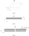
- a first aspect of this application provides a positive electrode plate 20.
- a three-dimensional rectangular coordinate system is established with a width direction of a secondary battery 10 as a direction X, a length direction of the secondary battery 10 as a direction Y, and a thickness direction of the secondary battery 10 as a direction Z.
- the secondary battery 10 includes a positive electrode plate 20, a negative electrode plate 30, and a separator 40 disposed between the positive electrode plate 20 and the negative electrode plate 30.
- the positive electrode plate 20 includes a positive electrode current collector 21 and a first coating 22 disposed on at least one surface of the positive electrode current collector 21.
- the "surface” herein may be an entire region or a partial region of the positive electrode current collector. This is not particularly limited in this application, provided that the objectives of this application can be achieved.
- a surface of the first coating 22 is provided with a conductive layer 23, and a surface of the conductive layer 23 is provided with a positive electrode active substance layer 24, where the first coating 22 includes a first material.
- the first material in this application may be comprise one or more selected from the group consisting of a layer-structured metal oxide, a spinel-structured metal oxide, a phosphate metal oxide and a ceramic material, and a conductivity of the conductive layer 23 is 0.02 S/cm to 1 S/cm.
- the first coating is disposed on at least one surface of the positive electrode current collector, and then the surface of the first coating is provided with the conductive layer; and the first material of the first coating comprises one or more selected from the group consisting of the layer-structured metal oxide, the spinel-structured metal oxide, the phosphate metal oxide and the ceramic material, and the conductivity of the conductive layer is within the foregoing range.
- the conductive layer includes a conductive material, the conductive material comprising one or more selected from the group consisting of carbon nanotubes, conductive carbon black and graphene material.
- the foregoing materials being selected as the conductive material in the conductive layer can improve conductive performance of the conductive layer, which reduces the contact impedance at the junction between the first coating and the positive electrode active substance layer, and alleviates the problem of high internal resistance of the positive electrode plate of the secondary battery, improving the rate performance of the secondary battery while enabling the secondary battery to have good safety performance.
- the conductive material includes the conductive carbon black and the carbon nanotubes, where a mass ratio of the conductive carbon black to the carbon nanotubes is 0.5:1 to 1.5:1.
- the conductive carbon black and the carbon nanotubes being selected to realize compounding of a granular conductive material and a linear long-range conductive material can further reduce resistance of the conductive layer, and make the conductive layer better disperse the current, which further reduces the contact impedance at the junction between the first coating and the positive electrode active substance layer, and alleviates the problem of high internal resistance of the positive electrode plate of the secondary battery, improving the rate performance of the secondary battery while enabling the secondary battery to have good safety performance.
- a mass percentage of the conductive material in the conductive layer is 50% to 95%.
- the mass percentage of the conductive material in the conductive layer being controlled within the foregoing range is conducive to improving the conductive performance of the conductive layer, which reduces the contact impedance at the junction between the first coating and the positive electrode active substance layer, and alleviates the problem of high internal resistance of the positive electrode plate of the secondary battery, improving the rate performance of the secondary battery while enabling the secondary battery to have good safety performance.
- thickness of the conductive layer is 1 ⁇ m to 10 ⁇ m
- thickness of the positive electrode current collector is 3 ⁇ m to 10 ⁇ m
- thickness of the first coating is 1 ⁇ m to 9 ⁇ m.
- D v 50 of the first material is 0.5 ⁇ m to 2 ⁇ m.
- D v 50 of the first material being controlled within the foregoing range can reduce side reactions between the first material and electrolyte, and enable the first material to have sufficient active surface, thereby improving the cycling performance and energy density of the secondary battery.
- D v 50 is a particle size of a material where the cumulative distribution by volume reaches 50% as counted from the small particle size.
- the ceramic material comprises one or more selected from the group consisting of aluminum oxide, boehmite, magnesium oxide, zirconium oxide, silicon oxide and calcium oxide.
- the foregoing materials being selected as the ceramic material is conducive to improving insulation performance of the first coating, thereby improving the rate performance of the secondary battery while enabling the secondary battery to have good safety performance.
- the first coating further includes a conductive agent and a binder, the conductive agent comprising one or more selected from the group consisting of carbon nanotubes, conductive carbon black and graphene material.
- the conductive agent comprising one or more selected from the group consisting of carbon nanotubes, conductive carbon black and graphene material.
- the foregoing materials being selected as the conductive agent can improve conductive performance of the first coating, thereby helping improve the rate performance of the secondary battery.
- the binder is not particularly limited in this application, provided that the invention objectives of this application can be achieved.
- the binder comprises one or more selected from the group consisting of polyvinylidene fluoride, vinylidene fluoride-hexafluoropropylene copolymer, polyacrylonitrile, polyacrylate ester, polyacrylic acid, polyacrylate salt, polyvinylpyrrolidone, polyamide, polyvinyl ether, polymethyl methacrylate, polytetrafluoroethylene, polyhexafluoropropylene, polypropylene, polyethylene, polyetherimide and copolymer of propylene hydrocarbon derivative.
- the binder being added to the first coating is conducive to improving adhesion strength between the first coating and the positive electrode current collector, thereby improving high-temperature storage performance of the secondary battery.
- the first coating includes lithium iron phosphate, a conductive agent, and a binder, where based on a total mass of the first coating, a mass percentage of the lithium iron phosphate is 70% to 90%, a mass percentage of the binder is 5% to 20%, and a mass percentage of the conductive agent is 1% to 10%.
- the mass percentages of the lithium iron phosphate, the conductive agent, and the binder being controlled within the foregoing ranges is conducive to improving mechanical safety performance and thermal safety of the first coating and obtaining a positive electrode plate with good structural stability, thereby improving the cycling performance of the secondary battery.
- the first coating includes a ceramic material, a conductive agent, and a binder, where based on a total mass of the first coating, a mass percentage of the ceramic material is 70% to 90%, a mass percentage of the binder is 5% to 20%, and a mass percentage of the conductive agent is 1% to 10%.
- a mass percentage of the ceramic material, the conductive agent, and the binder being controlled within the foregoing ranges is conducive to improving the safety performance of the first coating and obtaining a positive electrode plate with good structural stability, thereby improving the cycling performance of the secondary battery.
- the positive electrode active substance layer includes a positive electrode active substance, where the positive electrode active substance is selected from lithium cobalt oxide, lithium iron phosphate, lithium manganate, or nickel cobalt manganate ternary lithium material, and D v 50 of the positive electrode active substance is 10 ⁇ m to 20 ⁇ m.
- the foregoing materials being selected as the positive electrode active substance and D v 50 of the positive electrode active substance being controlled within the foregoing range are conducive to reducing side reactions between the positive electrode active substance and the electrolyte, and can enable the positive electrode active substance to have sufficient active surface, thereby improving the cycling performance and energy density of the secondary battery.
- an uncoated region (that is, a region not coated with the active substance layer) of the positive electrode plate is further provided with an inorganic coating.
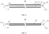
- the positive electrode plate 20 includes a first uncoated region 211 and a second uncoated region 212, where the second uncoated region 212 is welded with a tab 26.
- the inorganic coating 25 is disposed on the first uncoated region 211, and the inorganic coating 25 is located on one surface of the positive electrode current collector 21.
- Material and thickness of the inorganic coating are not particularly limited in this application.
- the material of the inorganic coating comprises one or more of boehmite and Al 2 O 3 , and the thickness is 1 ⁇ m to 9 ⁇ m.
- the layer-structured metal oxide may be selected from any one of LiCoO 2 , LiNiO 2 , LiNi 0.5 Co 0.2 Mn 0.3 O 2 , LiNi 1/3 Co 1/3 Mn 1/3 O 2 , or Li 2 MnO 3
- the spinel-structured metal oxide may be selected from any one of Li 2 MnO 4 or LiCo 0.5 Ni 0.25 Mn 1.25 O 4
- the phosphate metal oxide may be selected from any one of LiFePO 4 , LiCoPO 4 , or LiMnPO 4 .
- Thickness of the positive electrode active substance layer, D v 90 of the first material, D v 90 of the positive electrode active substance, and length-diameter ratio of the carbon nanotubes are not particularly limited in this application, provided that the invention objectives of this application can be achieved.
- the thickness of the positive electrode active substance layer is 100 ⁇ m to 800 ⁇ m
- D v 90 of the first material is ⁇ 3 ⁇ m
- D v 90 of the positive electrode active substance is ⁇ 35 ⁇ m
- the length-diameter ratio of the carbon nanotubes is 100 to 3000.
- D v 90 is a particle size of a material where the cumulative distribution by volume reaches 90% as counted from the small particle size.
- the positive electrode current collector is not particularly limited in this application, provided that the objectives of this application can be achieved.
- the positive electrode current collector may include aluminum foil, aluminum alloy foil, a composite current collector, or the like.
- the method for controlling the conductivity of the conductive layer is not particularly limited in this application, provided that the objectives of this application can be achieved.
- the conductivity of the conductive layer can be changed by selecting different conductive materials.
- the conductivity of the conductive layer generally increases with the increase of the percentage of the conductive material in the conductive layer, so the conductivity of the conductive layer can be controlled by controlling the percentage of the conductive material in the conductive layer.
- the preparation method of positive electrode plate is not particularly limited in this application, and any preparation methods well known in the art can be used, provided that the objectives of this application can be achieved.
- the preparation method of positive electrode plate includes but is not limited to the following steps: disperse a first material, a conductive agent, and a binder in an N-methylpyrrolidone (NMP) solvent, mix the mixture to form a uniform first coating slurry, and apply the first coating slurry onto a positive electrode current collector, followed by drying, as shown in FIG.
- NMP N-methylpyrrolidone
- a negative electrode plate includes a negative electrode current collector and a negative electrode active substance layer disposed on at least one surface of the negative electrode current collector.
- the "negative electrode active substance layer disposed on at least one surface of the negative electrode current collector” means that the negative electrode active substance layer may be disposed on one surface of the negative electrode current collector in its thickness direction, or on two surfaces of the negative electrode current collector in its thickness direction.
- the "surface” herein may be an entire region or a partial region of the negative electrode current collector. This is not particularly limited in this application, provided that the objectives of this application can be achieved.
- the negative electrode current collector is not particularly limited in this application, provided that the objectives of this application can be achieved.
- the negative electrode current collector may include copper foil, copper alloy foil, nickel foil, titanium foil, nickel foam, copper foam, or the like.
- the negative electrode active substance layer includes a negative electrode active substance.
- Type of the negative electrode active substance is not particularly limited in this application, provided that the objectives of this application can be achieved.
- the negative electrode active substance may comprise one or more selected from the group consisting of natural graphite, artificial graphite, soft carbon, hard carbon, meso-carbon microbeads, tin-based material, silicon-based material, lithium titanate, transition metal nitride and natural flake graphite.
- the negative electrode active substance layer further comprises one or more selected from the group consisting of a conductive agent, a thickener and a binder.
- the negative electrode binder may comprise but is not limited to one or more selected from the group consisting of polyvinyl alcohol, carboxymethyl cellulose, hydroxypropyl cellulose, diacetyl cellulose, polyvinyl chloride, carboxylated polyvinyl chloride, polyvinyl fluoride, polymer containing ethylene oxide, polyvinylpyrrolidone, polyurethane, polytetrafluoroethylene, poly(1,1-difluoroethylene), polyethylene, polypropylene, polyacrylic acid, styrene-butadiene rubber, acrylic styrene-butadiene rubber, epoxy resin and nylon.
- Mass ratio of the negative electrode active substance, the conductive agent, the thickener, and the binder in the negative electrode active substance layer is not particularly limited in this application, provided that the objectives of this application can be achieved.
- the mass ratio of the negative electrode active substance, the conductive agent, the thickener, and the binder in the negative electrode active substance layer is (97-98):(0-1.5):(0.5-1.5):(1.0-1.9).
- the negative electrode plate may further include a conductive layer, the conductive layer being located between the negative electrode current collector and the negative electrode active substance layer.
- Composition of the conductive layer is not particularly limited in this application, and the conductive layer may be a conductive layer commonly used in the art.
- the conductive layer may include but is not limited to the foregoing negative electrode conductive agent and negative electrode binder.
- a second aspect of this application provides a secondary battery including the positive electrode plate according to any one of the foregoing embodiments.
- a conductive layer with high conductive performance is used to connect the first coating and the positive electrode active substance layer, which reduces contact impedance at a junction between the first coating and the positive electrode active substance layer, and alleviates the problem of high internal resistance of the positive electrode plate.
- the secondary battery of this application is not particularly limited, and may include an apparatus in which an electrochemical reaction takes place.
- the secondary battery may include but is not limited to a lithium metal secondary battery, a lithium-ion secondary battery (lithium-ion battery), a lithium polymer secondary battery, and a lithium-ion polymer secondary battery.
- the secondary battery of this application further includes a separator.
- the separator is not particularly limited in this application, and persons skilled in the art can make selection based on actual needs, provided that the objectives of this application can be achieved.
- a material of the separator may comprise but is not limited to one or more selected from the group consisting of polyethylene (PE) and polypropylene (PP)-based polyolefin (PO), polyester (for example, polyethylene terephthalate (PET)), cellulose, polyimide (PI), polyamide (PA), spandex and aramid; and a type of the separator may comprise but is not limited to one or more selected from the group consisting of woven film, non-woven film (non-woven fabric), microporous film, composite film, separator paper, laminated film and spinning film.
- the separator may include a substrate layer and a surface treatment layer.
- the substrate layer may be a non-woven fabric, film, or composite film having a porous structure, and a material of the substrate layer may comprise one or more selected from the group consisting of polyethylene, polypropylene, polyethylene glycol terephthalate and polyimide.
- a polypropylene porous film, a polyethylene porous film, a polypropylene non-woven fabric, a polyethylene non-woven fabric, or a polypropylene-polyethylene-polypropylene porous composite film may be used.
- the surface treatment layer is provided on at least one surface of the substrate layer, and the surface treatment layer may be a polymer layer, an inorganic substance layer, or a layer formed by mixing a polymer and an inorganic substance.
- the inorganic substance layer includes inorganic particles and a binder.
- the inorganic particle is not particularly limited, and for example, may comprise one or more selected from the group consisting of aluminum oxide, silicon oxide, magnesium oxide, titanium oxide, hafnium oxide, tin oxide, ceria oxide, nickel oxide, zinc oxide, calcium oxide, zirconium oxide, yttrium oxide, silicon carbide, boehmite, aluminum hydroxide, magnesium hydroxide, calcium hydroxide and barium sulfate.
- the binder is not particularly limited, and for example, may comprise one or more selected from the group consisting of polyvinylidene fluoride, vinylidene fluoride-hexafluoropropylene copolymer, polyamide, polyacrylonitrile, polyacrylate ester, polyacrylic acid, polyacrylate salt, polyvinylpyrrolidone, polyvinyl ether, polymethyl methacrylate, polytetrafluoroethylene and polyhexafluoropropylene.
- the polymer layer includes a polymer, and a material of the polymer comprises one or more selected from the group consisting of polyamide, polyacrylonitrile, acrylate polymer, polyacrylic acid, polyacrylate salt, polyvinylpyrrolidone, polyvinyl ether, polyvinylidene fluoride and poly (vinylidene fluoride-hexafluoropropylene).
- the secondary battery of this application further includes an electrolyte.
- the electrolyte is not particularly limited in this application, and persons skilled in the art can make selection based on actual needs, provided that the objectives of this application can be achieved.
- one or more selected from the group consisting of ethylene carbonate (EC for short), propylene carbonate (PC), diethyl carbonate (DEC), ethyl propionate (EP), propyl propionate (PP), ethyl methyl carbonate (EMC), dimethyl carbonate (DMC), vinylene carbonate (VC) and fluoroethylene carbonate (FEC) is mixed at a specific mass ratio to obtain a non-aqueous organic solvent, and then a lithium salt is added for dissolving and mixing to uniformity.
- the “mass ratio” is not particularly limited in this application, provided that the objectives of this application can be achieved.
- Type of the lithium salt is not limited in this application, provided that the objectives of this application can be achieved.
- the lithium salt may comprise one or more selected from the group consisting of LiPF 6 , LiBF 4 , LiAsF 6 , LiClO 4 , LiB(C 6 H 5 ) 4 , LiCH 3 SO 3 , LiCF 3 SO 3 , LiN(SO 2 CF 3 ) 2 , LiC(SO 2 CF 3 ) 3 , LiSiF 6 , lithium bis(oxalato)borate (LiBOB) and lithium difluoroborate.
- Concentration of the lithium salt in the electrolyte is not particularly limited in this application, provided that the objectives of this application can be achieved.
- the concentration of the lithium salt is 1.0 mol/L to 2.0 mol/L.
- the secondary battery of this application further includes a housing.
- the housing is not particularly limited in this application, and persons skilled in the art can make selection based on actual needs, provided that the objectives of this application can be achieved.
- the housing may be an aluminum-plastic film, an aluminum shell, or a stainless steel shell.
- the preparation method of secondary battery is not particularly limited in this application, and any preparation methods well known in the art can be used, provided that the objectives of this application can be achieved.
- the preparation method of secondary battery includes but is not limited to the following steps: stack a positive electrode plate, a separator, and a negative electrode plate in sequence and perform operations such as winding and folding as needed to obtain an electrode assembly with a winding structure, put the electrode assembly into a packaging bag, and inject electrolyte into the packaging bag and seal the packaging bag to obtain an electrochemical apparatus.
- a third aspect of this application provides an electric apparatus including the secondary battery according to the foregoing embodiment.
- the electric apparatus is not particularly limited in this application, and may be a well-known electric apparatus used in the prior art.
- the electric apparatus may include but is not limited to a notebook computer, a pen-input computer, a mobile computer, an electronic book player, a portable telephone, a portable fax machine, a portable copier, a portable printer, a stereo headset, a video recorder, a liquid crystal television, a portable cleaner, a portable CD player, a mini-disc, a transceiver, an electronic notebook, a calculator, a storage card, a portable recorder, a radio, a standby power source, a motor, an automobile, a motorcycle, a motor bicycle, a bicycle, a lighting appliance, a toy, a game console, a clock, an electric tool, a flash lamp, a camera, a large household battery, or a lithium-ion capacitor.
- Particle size distributions of the conductive material in the conductive layer, the first material in the first coating, and the positive electrode active substance in the positive electrode active substance layer were tested using a laser particle size analyzer (model Mastersizer 3000) to obtain their D v 50 and D v 90.
- a film resistance tester (Initial Energy Science&Technology) was used to test internal resistance of wet-state samples of the positive electrode plate and internal resistance of the samples after drying at 60°C for 20 min. Before the test, alcohol was used to wipe the test probes of the film resistance tester, and then the pressure and resistance were reset to zero. The cut sample (60 mm ⁇ 80 mm) was placed flat on a sample carrier, and then the sample carrier was placed in a test chamber. 12 different positions of each positive electrode plate sample were taken for testing, and then the average value was calculated to obtain the wet-state internal resistance of the positive electrode plate and its internal resistance after drying at 60°C for 20 min, in mQ.
- a universal resistance tester (HT2572) was used to test the internal resistance of the secondary battery and its internal resistance after 60 days of storage under 1 kHz.
- the lithium-ion battery was placed on a flat iron plate as a test sample, and a nail with a diameter of 4 mm and a nail head angle of 30° penetrated perpendicular to the sample at a penetration speed of 30 mm/s.
- Pass criterion the lithium-ion battery that did not catch fire or explode passed the test.
- Nail penetration pass rate % pass number / 100 ⁇ 100 % .
- Lithium iron phosphate (LFP), carbon nanotubes (with a length-diameter ratio of 1000), and PVDF were mixed at a mass ratio of 80:5:15, then N-methylpyrrolidone (NMP) was added as solvent to obtain a first coating slurry with a solid content of 30wt%, and the slurry was stirred to uniformity. As shown in FIG.
- the first coating slurry was uniformly applied onto one surface of a 6 ⁇ m thick positive electrode current collector aluminum foil by using a gravure coating process, with two ends of the positive electrode current collector coated with no first coating slurry serving as uncoated regions, and then dried at 90°C to obtain a 5 ⁇ m thick first coating; and then the same steps were repeated on the other surface of the aluminum foil so that both surfaces were coated with a first coating.
- D v 50 of the first material lithium iron phosphate in the first coating was 1.2 ⁇ m.
- Conductive carbon black (SP), carbon nanotubes, and PVDF were mixed at a mass ratio of 30 : 30 : 40, then NMP was added as solvent to obtain a conductive layer slurry with a solid content of 30wt%, and the slurry was stirred to uniformity.
- the conductive layer slurry was uniformly applied onto the surface of the first coating on one side by using a transfer coating process, and then dried at 90°C to obtain a 5 ⁇ m thick conductive layer; and then the same steps were repeated on the surface of the first coating on the other side so that both surfaces were coated with a conductive layer.
- Conductivity of the conductive layer was 0.6 S/cm.
- Lithium cobalt oxide (LCO), PVDF, and conductive carbon black (SP) were mixed at a mass ratio of 97:1.5:1.5, then NMP was added as solvent to obtain a positive electrode active substance layer slurry with a solid content of 75wt%, and the slurry was stirred to uniformity.
- the positive electrode active substance layer slurry was uniformly applied onto the surface of the conductive layer on one side by using an extrusion coating process, and then dried at 90°C to obtain a 120 ⁇ m thick positive electrode active substance layer, where D v 50 of a positive electrode active substance in the positive electrode active substance layer was 15 ⁇ m. Then, the same steps were repeated on the surface of the conductive layer on the other side so that both surfaces were coated with a positive electrode active substance layer.
- Boehmite and PVDF were mixed at a mass ratio of 30:70, then NMP was added as solvent, and the mixture was stirred to uniformity by using a vacuum stirrer, to obtain an inorganic coating slurry with a solid content of 30wt%; and then the inorganic coating slurry was applied onto the first uncoated region of the positive electrode plate, and dried at 90°C to form an inorganic coating, where thickness of the inorganic coating was the same as the thickness of the first coating. Then, processes such as cold pressing, slitting, cutting, and tab welding were performed to obtain a positive electrode plate.
- the structure of the positive electrode plate is shown in FIG. 6 .
- the slurry was uniformly applied onto one surface of a 6 ⁇ m thick negative electrode current collector copper foil, and then dried at 85°C to obtain a negative electrode plate with a 120 ⁇ m thick negative electrode active substance layer; then the same steps were repeated on the other surface of the negative electrode plate to obtain a negative electrode plate coated with negative electrode active substances on two surfaces; and then the obtained negative electrode plate was subjected to cold pressing, slitting, cutting, and tab welding to obtain a negative electrode plate.
- EC, DEC, PC, PP, and VC were mixed at a mass ratio of 20:30:20:28:2 to obtain a non-aqueous organic solvent. Then, lithium salt LiPF 6 and the non-aqueous organic solvent were mixed at a mass ratio of 8:92 to obtain an electrolyte.
- a porous polyethylene film with a thickness of 7 ⁇ m was used.
- the prepared positive electrode plate, separator, and negative electrode plate were stacked in sequence, so that the separator was sandwiched between the positive electrode plate and the negative electrode plate for separation. Then, the resulting stack was wound to obtain an electrode assembly.
- the electrode assembly was placed into an aluminum-plastic film packaging bag and dried, and then the electrolyte was injected, followed by processes such as vacuum sealing, standing, formation, degassing, and trimming, to obtain a lithium-ion battery.
- Example 2 to Example 5 were the same as Example 1 except that in "Preparation of positive electrode plate", the conductivity of the conductive layer was adjusted according to Table 1 by adjusting the percentage of the conductive materials in the conductive layer.
- Example 6 and Example 7 were the same as Example 1 except that in “Preparation of positive electrode plate", the thickness of the conductive layer was adjusted according to Table 1.
- Example 8 and Example 9 were the same as Example 1 except that in "Preparation of positive electrode plate", the conductivity of the conductive layer was adjusted according to Table 1 by adjusting the mass ratio of the conductive carbon black to the carbon nanotubes in the conductive layer according to Table 1.
- Example 10 to Example 13 were the same as Example 1 except that in "Preparation of positive electrode plate", the type of the first material in the first coating and the mass percentages of the components were adjusted according to Table 1.
- Example 14 and Example 15 were the same as Example 1 except that in "Preparation of positive electrode plate", the thickness of the first coating and D v 50 of the first material in the first coating were adjusted according to Table 1.
- Example 16 to Example 20 were the same as Example 1 except that in "Preparation of positive electrode plate", the type and D v 50 of the positive electrode active substance in the positive electrode active substance layer were adjusted according to Table 1.
- Example 21 and Example 22 were the same as Example 1 except that in "Preparation of positive electrode plate", the thickness of the positive electrode current collector was adjusted according to Table 1.
- Example 23 to Example 25 were the same as Example 1 except that in "Preparation of positive electrode plate", the type of the conductive material was adjusted according to Table 1.
- Comparative Example 1 was the same as Example 1 except that in "Preparation of positive electrode plate", the conductive layer was not applied, to form the structure shown in FIG. 7 .
- Comparative Example 2 was the same as Example 1 except that in "Preparation of positive electrode plate", the conductive layer was applied onto the surface of the positive electrode current collector first, and then the first coating was applied onto the surface of the conductive layer, to form the structure shown in FIG. 8 .
- Comparative Example 3 was the same as Example 1 except that in "Preparation of positive electrode plate", the first coating and the conductive layer were not applied, to form the structure shown in FIG. 9 .
- Comparative Example 4 and Comparative Example 5 were the same as Example 1 except that in "Preparation of positive electrode plate", the conductivity of the conductive layer was adjusted according to Table 1 by adjusting the percentage of the conductive materials in the conductive layer.
- Example 1 and Table 2 it can be learned from Example 1 to Example 25 and Comparative Example 1 to Comparative Example 5 that because the positive electrode plate in Comparative Example 1 does not have the conductive layer, although it has a high nail penetration pass rate, the interfacial contact resistance between the positive electrode active substance layer and the first coating is higher than the interfacial contact resistance between the conductive layer and the positive electrode active substance layer and the interfacial contact resistance between the conductive layer and the first coating, which causes that the internal resistance of the battery after drying at 60°C for 20 min, the internal resistance of the lithium-ion battery, and the internal resistance of the lithium-ion battery after 60 days of storage in Comparative Example 1 are significantly higher than those in Example 1, whereas high internal resistance affects the rate performance of the lithium-ion battery.
- the conductive layer is applied onto the surface of the positive electrode current collector first, and then the first coating is applied onto the surface of the conductive layer. Therefore, the conductive layer is disposed between the first coating and the positive electrode current collector, which significantly reduces the interfacial contact impedance between the first coating and the positive electrode current collector, so that the internal resistance of the positive electrode plate after drying at 60°C for 20 min, the internal resistance of the lithium-ion battery, and the internal resistance of the lithium-ion battery after 60 days of storage in Comparative Example 2 are low.
- the nail penetration pass rate of the lithium-ion battery in Comparative Example 2 is only 0%.
- Comparative Example 3 does not have the first coating and the conductive layer, although the internal resistance of the lithium-ion battery and the internal resistance of the lithium-ion battery after 60 days of storage in Comparative Example 3 are low, the risk of short circuit of the lithium-ion battery is increased due to the absence of the first coating in the positive electrode plate, and the nail penetration pass rate of the lithium-ion battery is 0%, resulting in poor safety performance of the lithium-ion battery.
- the conductivity of the conductive layer is excessively low (for example, Comparative Example 4), and the internal resistance of the positive electrode plate after drying at 60°C for 20 min, the internal resistance of the lithium-ion battery, and the internal resistance of the lithium-ion battery after 60 days of storage are all high, and the high internal resistance affects the rate performance of the lithium-ion battery.
- the internal resistance of the positive electrode plate after drying at 60°C for 20 min, the internal resistance of the lithium-ion battery, and the internal resistance of the lithium-ion battery after 60 days of storage are comparatively low, which is conducive to the rate performance and suppression of temperature rise of the battery.
- the adhesion force is insufficient, which causes the positive electrode active substance layer to be prone to peel off during cycling, deteriorating the cycling stability of the battery, not conducive to improving the long-term cycling performance of the battery.
- the conductivity of the conductive layer within the range of this application and through synergy of the structural design and the material selection, the contact impedance at the junction between the first coating and the positive electrode active substance layer is reduced, and the problem of high internal resistance of the positive electrode plate of the lithium-ion battery is alleviated, improving the rate performance of the lithium-ion battery while enabling the lithium-ion battery to have good safety performance.
- the thickness of the conductive layer, the type and ratio of the conductive materials of the conductive layer, the thickness of the first coating, the particle size of the first material of the first coating, the ratio of the components of the first coating, the type and particle size of the positive electrode active substance, and the thickness of the positive electrode current collector generally also affect the performance of the lithium-ion battery. It can be learned from Example 6 to Example 25 that lithium-ion batteries with good safety performance and rate performance can also be obtained by controlling the foregoing parameters within the ranges of this application.
Landscapes
- Chemical & Material Sciences (AREA)
- Engineering & Computer Science (AREA)
- Materials Engineering (AREA)
- Chemical Kinetics & Catalysis (AREA)
- Electrochemistry (AREA)
- General Chemical & Material Sciences (AREA)
- Composite Materials (AREA)
- Battery Electrode And Active Subsutance (AREA)
Abstract
A positive electrode plate (20) includes a positive electrode current collector (21), a first coating (22), a conductive layer (23) and a positive electrode active substance layer (24). The first coating (22) is disposed on at least one surface of the positive electrode current collector (21), the conductive layer (23) is disposed on a surface of the first coating (22), and the positive electrode active substance layer (24) is disposed on a surface of the conductive layer (23); and the first coating (22) is controlled to include a first material, where the first material comprises one or more selected from the group consisting of a layer-structured metal oxide, a spinel-structured metal oxide, a phosphate metal oxide and a ceramic material, and a conductivity of the conductive layer (23) is 0.02 S/cm to 1 S/cm.
Description
- This application relates to the field of electrochemical technologies, and in particular, to a positive electrode plate, a secondary battery, and an electric apparatus.
- Due to advantages such as high energy density, low self-discharge, no memory effect, and long cycle life, secondary batteries, such as lithium-ion batteries, have been widely used in fields such as portable electronic devices, electric vehicles, unmanned aerial vehicles, and large-scale energy storage devices.
- To meet the increasingly high requirements of people for the safety performance of lithium-ion batteries, a safety coating is applied onto the surface of the positive electrode current collector to improve the safety of secondary batteries. However, the safety coating increases the internal resistance of the positive electrode plate, which leads to excessively rapid temperature rise of the secondary batteries during charging, affecting the rate performance of the secondary batteries.
- This application is intended to provide a positive electrode plate, a secondary battery, and an electric apparatus, so as to improve rate performance of the secondary battery while enabling the secondary battery to have good safety performance.
- It should be noted that in the content of this application, an example in which a lithium-ion battery is used as a secondary battery is used to illustrate this application. However, the secondary battery of this application is not limited to the lithium-ion battery. Specific technical solutions are as follows.
- A first aspect of this application provides a positive electrode plate including a positive electrode current collector and a first coating disposed on at least one surface of the positive electrode current collector, where a surface of the first coating is provided with a conductive layer, and a surface of the conductive layer is provided with a positive electrode active substance layer, where the first coating includes a first material. The first material in this application may comprise one or more selected from the group consisting of a layer-structured metal oxide, a spinel-structured metal oxide, a phosphate metal oxide and a ceramic material, and a conductivity of the conductive layer in this application is 0.02 S/cm to 1 S/cm. In the positive electrode plate, the first coating is disposed on at least one surface of the positive electrode current collector, and then the surface of the first coating is provided with the conductive layer; and the first coating is controlled to include the first material, where the first material comprises one or more selected from the group consisting of the layer-structured metal oxide, the spinel-structured metal oxide, the phosphate metal oxide and the ceramic material, and the conductivity of the conductive layer is controlled within the foregoing range. Through synergy of the foregoing structural design and material selection, contact impedance at a junction between the first coating and the positive electrode active substance layer is reduced, and the problem of high internal resistance of the positive electrode plate of the secondary battery is alleviated, improving rate performance of the secondary battery while enabling the secondary battery to have good safety performance.
- In some embodiments of this application, the conductive layer includes a conductive material, the conductive material comprising one or more selected from the group consisting of carbon nanotubes, conductive carbon black and graphene material. The foregoing materials being selected as the conductive material in the conductive layer can improve conductive performance of the conductive layer, which reduces the contact impedance at the junction between the first coating and the positive electrode active substance layer, and alleviates the problem of high internal resistance of the positive electrode plate of the secondary battery, improving the rate performance of the secondary battery while enabling the secondary battery to have good safety performance.
- In some embodiments of this application, the conductive material includes the conductive carbon black and the carbon nanotubes, where a mass ratio of the conductive carbon black to the carbon nanotubes is 0.5:1 to 1.5:1. The conductive carbon black and the carbon nanotubes being selected to realize compounding of a granular conductive material and a linear long-range conductive material can further reduce resistance of the conductive layer, and make the conductive layer better disperse the current, which further reduces the contact impedance at the junction between the first coating and the positive electrode active substance layer, and alleviates the problem of high internal resistance of the positive electrode plate of the secondary battery, improving the rate performance of the secondary battery while enabling the secondary battery to have good safety performance.
- In some embodiments of this application, a mass percentage of the conductive material in the conductive layer is 50% to 95%. In this application, the mass percentage of the conductive material in the conductive layer being controlled within the foregoing range is conducive to improving the conductive performance of the conductive layer, which reduces the contact impedance at the junction between the first coating and the positive electrode active substance layer, and alleviates the problem of high internal resistance of the positive electrode plate of the secondary battery, improving the rate performance of the secondary battery while enabling the secondary battery to have good safety performance.
- In some embodiments of this application, thickness of the conductive layer is 1 µm to 10 µm, thickness of the positive electrode current collector is 3 µm to 10 µm, and thickness of the first coating is 1 µm to 9 µm. Without being bound by any theory, the thickness of the conductive layer, the thickness of the positive electrode current collector, and the thickness of the first coating being controlled within the foregoing ranges is conducive to maintaining good structural stability of the structural layers of the positive electrode plate, ensuring energy density of the battery while reducing the risk of breakage of the electrode plate.
- In some embodiments of this application, Dv50 of the first material is 0.5 µm to 2 µm. Without being bound by any theory, Dv50 of the first material being controlled within the foregoing range can reduce side reactions between the first material and electrolyte, and enable the first material to have sufficient active surface, thereby improving the cycling performance and energy density of the secondary battery. According to this application, Dv50 is a particle size where the cumulative distribution by volume reaches 50% as counted from the small particle size; and Dv90 described below is a particle size where the cumulative distribution by volume reaches 90% as counted from the small particle size.
- In some embodiments of this application, the ceramic material comprises one or more selected from the group consisting of aluminum oxide, boehmite, magnesium oxide, zirconium oxide, silicon oxide and calcium oxide. The foregoing materials being selected as the ceramic material is conducive to improving insulation performance of the first coating, thereby improving the rate performance of the secondary battery while enabling the secondary battery to have good safety performance.
- In some embodiments of this application, the first coating further includes a conductive agent and a binder, the conductive agent comprising one or more selected from the group consisting of carbon nanotubes, conductive carbon black and graphene material. The foregoing materials being selected as the conductive agent can improve conductive performance of the first coating, thereby helping improve the rate performance of the secondary battery. The binder being added to the first coating is conducive to improving adhesion strength between the first coating and the positive electrode current collector, thereby improving high-temperature storage performance of the secondary battery.
- In some embodiments of this application, the first coating includes lithium iron phosphate, a conductive agent, and a binder, where based on a total mass of the first coating, a mass percentage of the lithium iron phosphate is 70% to 90%, a mass percentage of the binder is 5% to 20%, and a mass percentage of the conductive agent is 1% to 10%. Without being bound by any theory, the mass percentages of the lithium iron phosphate, the conductive agent, and the binder being controlled within the foregoing ranges is conducive to improving safety performance of the first coating and obtaining a positive electrode plate with good structural stability, thereby improving the cycling performance of the secondary battery.
- In some embodiments of this application, the first coating includes a ceramic material, a conductive agent, and a binder, where based on a total mass of the first coating, a mass percentage of the ceramic material is 70% to 90%, a mass percentage of the binder is 5% to 20%, and a mass percentage of the conductive agent is 1% to 10%. Without being bound by any theory, the mass percentages of the ceramic material, the conductive agent, and the binder being controlled within the foregoing ranges is conducive to improving the safety performance of the first coating and obtaining a positive electrode plate with good structural stability, thereby improving the cycling performance of the secondary battery.
- In some embodiments of this application, the positive electrode active substance layer includes a positive electrode active substance, where the positive electrode active substance is selected from lithium cobalt oxide, lithium iron phosphate, lithium manganese iron phosphate, lithium manganate, or lithium nickel cobalt manganate, and Dv50 of the positive electrode active substance is 10 µm to 20 µm. The foregoing materials being selected as the positive electrode active substance and Dv50 of the positive electrode active substance being controlled within the foregoing range are conducive to reducing side reactions between the positive electrode active substance and the electrolyte, and can enable the positive electrode active substance to have sufficient active surface, thereby improving the cycling performance and energy density of the secondary battery.
- A second aspect of this application provides a secondary battery including the positive electrode plate according to any one of the foregoing embodiments. In the positive electrode plate provided in this application, a conductive layer with high conductive performance is used to connect the first coating and the positive electrode active substance layer, which significantly reduces contact impedance at a junction between the first coating and the positive electrode active substance layer, and alleviates the problem of high internal resistance of the positive electrode plate, reducing internal resistance of the secondary battery.
- A third aspect of this application provides an electric apparatus including the secondary battery according to the foregoing embodiment. The secondary battery provided in this application has low internal resistance, such that the electric apparatus provided in this application has good cycling performance and rate performance.
- In the positive electrode plate, the secondary battery, and the electric apparatus provided in this application, the first coating is disposed on at least one surface of the positive electrode current collector, the conductive layer is disposed on the surface of the first coating, and the positive electrode active substance layer is disposed on the surface of the conductive layer; and the first coating is controlled to include the first material, where the first material comprises one or more selected from the group consisting of layer-structured metal oxide, spinel-structured metal oxide, phosphate metal oxide and ceramic material, and the conductivity of the conductive layer is 0.02 S/cm to 1 S/cm. In this application, a conductive layer with high conductive performance is used to connect the first coating and the positive electrode active substance layer, which significantly reduces contact impedance at a junction between the first coating and the positive electrode active substance layer, and alleviates the problem of high internal resistance of the positive electrode plate of the secondary battery, improving rate performance of the secondary battery while enabling the secondary battery to have good safety performance. Certainly, when any one of the products or methods of this application is implemented, the advantages described above are not necessarily demonstrated all at the same time.
- To describe the technical solutions in some embodiments of this application and in the prior art more clearly, the following briefly describes the accompanying drawings required for describing some embodiments and the prior art. Apparently, the accompanying drawings in the following descriptions show only some embodiments of this application, and persons of ordinary skill in the art may still derive other drawings from these accompanying drawings.
-
FIG. 1 is a schematic structural diagram of a secondary battery according to some embodiments of this application; -
FIG. 2 is a schematic structural diagram of a cross section of a secondary battery according to some embodiments of this application along its thickness direction; -
FIG. 3 is a schematic structural diagram of a cross section of a positive electrode plate according to some embodiments of this application along its thickness direction; -
FIG. 4 is a schematic structural diagram of a cross section of a positive electrode current collector coated with a first coating according to some embodiments of this application along its thickness direction; -
FIG. 5 is a schematic structural diagram of a cross section of a positive electrode current collector coated with a first coating and a conductive layer according to some embodiments of this application along its thickness direction; -
FIG. 6 is a schematic structural diagram of a cross section of a positive electrode plate according to some other embodiments of this application along its thickness direction; -
FIG. 7 is a schematic structural diagram of a cross section of a positive electrode plate in Comparative Example 1 of this application along its thickness direction; -
FIG. 8 is a schematic structural diagram of a cross section of a positive electrode plate in Comparative Example 2 of this application along its thickness direction; and -
FIG. 9 is a schematic structural diagram of a cross section of a positive electrode plate in Comparative Example 3 of this application along its thickness direction. - Reference signs: 10. secondary battery, 20. positive electrode plate, 21. positive electrode current collector, 22. first coating, 23. conductive layer, 24. positive electrode active substance layer, 25. inorganic coating, 26. tab, 30. negative electrode plate, 40. separator, 211. first uncoated region, and 212. second uncoated region.
- To make the objectives, technical solutions, and advantages of this application more comprehensible, the following describes this application in detail with reference to accompanying drawings and embodiments. Apparently, the described embodiments are merely some but not all of the embodiments of this application. All other embodiments obtained by persons of ordinary skill in the art based on some embodiments of this application shall fall within the protection scope of this application.
- It should be noted that in specific embodiments, an example in which a lithium-ion battery is used as a secondary battery is used to illustrate this application. However, the secondary battery of this application is not limited to the lithium-ion battery. Specific technical solutions are as follows:
The inventors have found that in the prior art, a safety coating (that is, the first coating according to this application) is applied onto a positive electrode current collector to improve safety in a nail penetration test or an impact test. However, resistance of the safety coating is higher than that of an active substance layer. Due to the presence of the safety coating, two interfaces, one between the safety coating and the positive electrode active substance layer and the other between the safety coating and the positive electrode current collector, are formed inside a positive electrode plate, resulting in increased internal resistance of the positive electrode plate, affecting rate performance of a secondary battery. - In view of this, a first aspect of this application provides a
positive electrode plate 20. For ease of understanding, as shown inFIG. 1 , a three-dimensional rectangular coordinate system is established with a width direction of asecondary battery 10 as a direction X, a length direction of thesecondary battery 10 as a direction Y, and a thickness direction of thesecondary battery 10 as a direction Z. As shown inFIG. 2 , thesecondary battery 10 includes apositive electrode plate 20, anegative electrode plate 30, and aseparator 40 disposed between thepositive electrode plate 20 and thenegative electrode plate 30. As shown inFIG. 3 , thepositive electrode plate 20 includes a positive electrodecurrent collector 21 and afirst coating 22 disposed on at least one surface of the positive electrodecurrent collector 21. The "surface" herein may be an entire region or a partial region of the positive electrode current collector. This is not particularly limited in this application, provided that the objectives of this application can be achieved. A surface of thefirst coating 22 is provided with aconductive layer 23, and a surface of theconductive layer 23 is provided with a positive electrodeactive substance layer 24, where thefirst coating 22 includes a first material. The first material in this application may be comprise one or more selected from the group consisting of a layer-structured metal oxide, a spinel-structured metal oxide, a phosphate metal oxide and a ceramic material, and a conductivity of theconductive layer 23 is 0.02 S/cm to 1 S/cm. In the positive electrode plate, the first coating is disposed on at least one surface of the positive electrode current collector, and then the surface of the first coating is provided with the conductive layer; and the first material of the first coating comprises one or more selected from the group consisting of the layer-structured metal oxide, the spinel-structured metal oxide, the phosphate metal oxide and the ceramic material, and the conductivity of the conductive layer is within the foregoing range. Through synergy of the foregoing structural design and material selection, contact impedance at a junction between the first coating and the positive electrode active substance layer is reduced, and the problem of high internal resistance of the positive electrode plate of the secondary battery is alleviated, which means that internal resistance of the secondary battery is reduced, improving rate performance of the secondary battery while enabling the secondary battery to have good safety performance. - In some embodiments of this application, the conductive layer includes a conductive material, the conductive material comprising one or more selected from the group consisting of carbon nanotubes, conductive carbon black and graphene material. The foregoing materials being selected as the conductive material in the conductive layer can improve conductive performance of the conductive layer, which reduces the contact impedance at the junction between the first coating and the positive electrode active substance layer, and alleviates the problem of high internal resistance of the positive electrode plate of the secondary battery, improving the rate performance of the secondary battery while enabling the secondary battery to have good safety performance.
- In some embodiments of this application, the conductive material includes the conductive carbon black and the carbon nanotubes, where a mass ratio of the conductive carbon black to the carbon nanotubes is 0.5:1 to 1.5:1. The conductive carbon black and the carbon nanotubes being selected to realize compounding of a granular conductive material and a linear long-range conductive material can further reduce resistance of the conductive layer, and make the conductive layer better disperse the current, which further reduces the contact impedance at the junction between the first coating and the positive electrode active substance layer, and alleviates the problem of high internal resistance of the positive electrode plate of the secondary battery, improving the rate performance of the secondary battery while enabling the secondary battery to have good safety performance.
- In some embodiments of this application, a mass percentage of the conductive material in the conductive layer is 50% to 95%. In this application, the mass percentage of the conductive material in the conductive layer being controlled within the foregoing range is conducive to improving the conductive performance of the conductive layer, which reduces the contact impedance at the junction between the first coating and the positive electrode active substance layer, and alleviates the problem of high internal resistance of the positive electrode plate of the secondary battery, improving the rate performance of the secondary battery while enabling the secondary battery to have good safety performance.
- In some embodiments of this application, thickness of the conductive layer is 1 µm to 10 µm, thickness of the positive electrode current collector is 3 µm to 10 µm, and thickness of the first coating is 1 µm to 9 µm. Without being bound by any theory, the thickness of the conductive layer, the thickness of the positive electrode current collector, and the thickness of the first coating being controlled within the foregoing ranges is conducive to maintaining good structural stability of the structural layers of the positive electrode plate, ensuring energy density of the battery while reducing the risk of breakage of the positive electrode plate.
- In some embodiments of this application, Dv50 of the first material is 0.5 µm to 2 µm. Without being bound by any theory, Dv50 of the first material being controlled within the foregoing range can reduce side reactions between the first material and electrolyte, and enable the first material to have sufficient active surface, thereby improving the cycling performance and energy density of the secondary battery. Dv50 is a particle size of a material where the cumulative distribution by volume reaches 50% as counted from the small particle size.
- In some embodiments of this application, the ceramic material comprises one or more selected from the group consisting of aluminum oxide, boehmite, magnesium oxide, zirconium oxide, silicon oxide and calcium oxide. The foregoing materials being selected as the ceramic material is conducive to improving insulation performance of the first coating, thereby improving the rate performance of the secondary battery while enabling the secondary battery to have good safety performance.
- In some embodiments of this application, the first coating further includes a conductive agent and a binder, the conductive agent comprising one or more selected from the group consisting of carbon nanotubes, conductive carbon black and graphene material. The foregoing materials being selected as the conductive agent can improve conductive performance of the first coating, thereby helping improve the rate performance of the secondary battery. The binder is not particularly limited in this application, provided that the invention objectives of this application can be achieved. For example, the binder comprises one or more selected from the group consisting of polyvinylidene fluoride, vinylidene fluoride-hexafluoropropylene copolymer, polyacrylonitrile, polyacrylate ester, polyacrylic acid, polyacrylate salt, polyvinylpyrrolidone, polyamide, polyvinyl ether, polymethyl methacrylate, polytetrafluoroethylene, polyhexafluoropropylene, polypropylene, polyethylene, polyetherimide and copolymer of propylene hydrocarbon derivative. The binder being added to the first coating is conducive to improving adhesion strength between the first coating and the positive electrode current collector, thereby improving high-temperature storage performance of the secondary battery.
- In some embodiments of this application, the first coating includes lithium iron phosphate, a conductive agent, and a binder, where based on a total mass of the first coating, a mass percentage of the lithium iron phosphate is 70% to 90%, a mass percentage of the binder is 5% to 20%, and a mass percentage of the conductive agent is 1% to 10%. Without being bound by any theory, the mass percentages of the lithium iron phosphate, the conductive agent, and the binder being controlled within the foregoing ranges is conducive to improving mechanical safety performance and thermal safety of the first coating and obtaining a positive electrode plate with good structural stability, thereby improving the cycling performance of the secondary battery.
- In some embodiments of this application, the first coating includes a ceramic material, a conductive agent, and a binder, where based on a total mass of the first coating, a mass percentage of the ceramic material is 70% to 90%, a mass percentage of the binder is 5% to 20%, and a mass percentage of the conductive agent is 1% to 10%. Without being bound by any theory, the mass percentages of the ceramic material, the conductive agent, and the binder being controlled within the foregoing ranges is conducive to improving the safety performance of the first coating and obtaining a positive electrode plate with good structural stability, thereby improving the cycling performance of the secondary battery.
- In some embodiments of this application, the positive electrode active substance layer includes a positive electrode active substance, where the positive electrode active substance is selected from lithium cobalt oxide, lithium iron phosphate, lithium manganate, or nickel cobalt manganate ternary lithium material, and Dv50 of the positive electrode active substance is 10 µm to 20 µm. The foregoing materials being selected as the positive electrode active substance and Dv50 of the positive electrode active substance being controlled within the foregoing range are conducive to reducing side reactions between the positive electrode active substance and the electrolyte, and can enable the positive electrode active substance to have sufficient active surface, thereby improving the cycling performance and energy density of the secondary battery.
- In some embodiments of this application, an uncoated region (that is, a region not coated with the active substance layer) of the positive electrode plate is further provided with an inorganic coating. As shown in
FIG. 6 , along the direction X, thepositive electrode plate 20 includes a firstuncoated region 211 and a seconduncoated region 212, where the seconduncoated region 212 is welded with atab 26. Theinorganic coating 25 is disposed on the firstuncoated region 211, and theinorganic coating 25 is located on one surface of the positive electrodecurrent collector 21. The foregoing structure can improve the safety performance of the secondary battery. Material and thickness of the inorganic coating are not particularly limited in this application. For example, the material of the inorganic coating comprises one or more of boehmite and Al2O3, and the thickness is 1 µm to 9 µm. - Types of the layer-structured metal oxide, the spinel-structured metal oxide, and the phosphate metal oxide are not particularly limited in this application, provided that the invention objectives of this application can be achieved. For example, the layer-structured metal oxide may be selected from any one of LiCoO2, LiNiO2, LiNi0.5Co0.2Mn0.3O2, LiNi1/3Co1/3Mn1/3O2, or Li2MnO3, the spinel-structured metal oxide may be selected from any one of Li2MnO4 or LiCo0.5Ni0.25Mn1.25O4, and the phosphate metal oxide may be selected from any one of LiFePO4, LiCoPO4, or LiMnPO4.
- Thickness of the positive electrode active substance layer, Dv90 of the first material, Dv90 of the positive electrode active substance, and length-diameter ratio of the carbon nanotubes are not particularly limited in this application, provided that the invention objectives of this application can be achieved. For example, the thickness of the positive electrode active substance layer is 100 µm to 800 µm, Dv90 of the first material is ≤ 3 µm, Dv90 of the positive electrode active substance is ≤ 35 µm, and the length-diameter ratio of the carbon nanotubes is 100 to 3000. Dv90 is a particle size of a material where the cumulative distribution by volume reaches 90% as counted from the small particle size.
- The positive electrode current collector is not particularly limited in this application, provided that the objectives of this application can be achieved. For example, the positive electrode current collector may include aluminum foil, aluminum alloy foil, a composite current collector, or the like.
- The method for controlling the conductivity of the conductive layer is not particularly limited in this application, provided that the objectives of this application can be achieved. For example, the conductivity of the conductive layer can be changed by selecting different conductive materials. Alternatively, for another example, the conductivity of the conductive layer generally increases with the increase of the percentage of the conductive material in the conductive layer, so the conductivity of the conductive layer can be controlled by controlling the percentage of the conductive material in the conductive layer.
- The preparation method of positive electrode plate is not particularly limited in this application, and any preparation methods well known in the art can be used, provided that the objectives of this application can be achieved. For example, the preparation method of positive electrode plate includes but is not limited to the following steps: disperse a first material, a conductive agent, and a binder in an N-methylpyrrolidone (NMP) solvent, mix the mixture to form a uniform first coating slurry, and apply the first coating slurry onto a positive electrode current collector, followed by drying, as shown in
FIG. 4 ; then disperse a conductive material and a binder in an N-methylpyrrolidone (NMP) solvent, mix the mixture to form a uniform conductive layer slurry, and apply the conductive layer slurry onto a surface of the first coating, followed by drying, as shown inFIG. 5 ; and then disperse a positive electrode active substance, a conductive agent, and a binder in an N-methylpyrrolidone (NMP) solvent, mix the mixture to form a uniform positive electrode active substance layer slurry, and apply the positive electrode active substance layer slurry onto a surface of the conductive layer, followed by drying, cold pressing, cutting, slitting, and re-drying, to obtain the positive electrode plate shown inFIG. 3 . - In this application, a negative electrode plate includes a negative electrode current collector and a negative electrode active substance layer disposed on at least one surface of the negative electrode current collector. The "negative electrode active substance layer disposed on at least one surface of the negative electrode current collector" means that the negative electrode active substance layer may be disposed on one surface of the negative electrode current collector in its thickness direction, or on two surfaces of the negative electrode current collector in its thickness direction. The "surface" herein may be an entire region or a partial region of the negative electrode current collector. This is not particularly limited in this application, provided that the objectives of this application can be achieved. The negative electrode current collector is not particularly limited in this application, provided that the objectives of this application can be achieved. For example, the negative electrode current collector may include copper foil, copper alloy foil, nickel foil, titanium foil, nickel foam, copper foam, or the like. The negative electrode active substance layer includes a negative electrode active substance. Type of the negative electrode active substance is not particularly limited in this application, provided that the objectives of this application can be achieved. For example, the negative electrode active substance may comprise one or more selected from the group consisting of natural graphite, artificial graphite, soft carbon, hard carbon, meso-carbon microbeads, tin-based material, silicon-based material, lithium titanate, transition metal nitride and natural flake graphite. Optionally, the negative electrode active substance layer further comprises one or more selected from the group consisting of a conductive agent, a thickener and a binder. Types of the conductive agent, the thickener, and the binder in the negative electrode active substance layer are not particularly limited in this application, provided that the objectives of this application can be achieved. For example, the negative electrode binder may comprise but is not limited to one or more selected from the group consisting of polyvinyl alcohol, carboxymethyl cellulose, hydroxypropyl cellulose, diacetyl cellulose, polyvinyl chloride, carboxylated polyvinyl chloride, polyvinyl fluoride, polymer containing ethylene oxide, polyvinylpyrrolidone, polyurethane, polytetrafluoroethylene, poly(1,1-difluoroethylene), polyethylene, polypropylene, polyacrylic acid, styrene-butadiene rubber, acrylic styrene-butadiene rubber, epoxy resin and nylon. Mass ratio of the negative electrode active substance, the conductive agent, the thickener, and the binder in the negative electrode active substance layer is not particularly limited in this application, provided that the objectives of this application can be achieved. For example, the mass ratio of the negative electrode active substance, the conductive agent, the thickener, and the binder in the negative electrode active substance layer is (97-98):(0-1.5):(0.5-1.5):(1.0-1.9).
- Optionally, the negative electrode plate may further include a conductive layer, the conductive layer being located between the negative electrode current collector and the negative electrode active substance layer. Composition of the conductive layer is not particularly limited in this application, and the conductive layer may be a conductive layer commonly used in the art. The conductive layer may include but is not limited to the foregoing negative electrode conductive agent and negative electrode binder.
- A second aspect of this application provides a secondary battery including the positive electrode plate according to any one of the foregoing embodiments. In the positive electrode plate provided in this application, a conductive layer with high conductive performance is used to connect the first coating and the positive electrode active substance layer, which reduces contact impedance at a junction between the first coating and the positive electrode active substance layer, and alleviates the problem of high internal resistance of the positive electrode plate. The secondary battery of this application is not particularly limited, and may include an apparatus in which an electrochemical reaction takes place. For example, the secondary battery may include but is not limited to a lithium metal secondary battery, a lithium-ion secondary battery (lithium-ion battery), a lithium polymer secondary battery, and a lithium-ion polymer secondary battery.
- The secondary battery of this application further includes a separator. The separator is not particularly limited in this application, and persons skilled in the art can make selection based on actual needs, provided that the objectives of this application can be achieved. For example, a material of the separator may comprise but is not limited to one or more selected from the group consisting of polyethylene (PE) and polypropylene (PP)-based polyolefin (PO), polyester (for example, polyethylene terephthalate (PET)), cellulose, polyimide (PI), polyamide (PA), spandex and aramid; and a type of the separator may comprise but is not limited to one or more selected from the group consisting of woven film, non-woven film (non-woven fabric), microporous film, composite film, separator paper, laminated film and spinning film. For example, the separator may include a substrate layer and a surface treatment layer. The substrate layer may be a non-woven fabric, film, or composite film having a porous structure, and a material of the substrate layer may comprise one or more selected from the group consisting of polyethylene, polypropylene, polyethylene glycol terephthalate and polyimide. Optionally, a polypropylene porous film, a polyethylene porous film, a polypropylene non-woven fabric, a polyethylene non-woven fabric, or a polypropylene-polyethylene-polypropylene porous composite film may be used. Optionally, the surface treatment layer is provided on at least one surface of the substrate layer, and the surface treatment layer may be a polymer layer, an inorganic substance layer, or a layer formed by mixing a polymer and an inorganic substance. For example, the inorganic substance layer includes inorganic particles and a binder. The inorganic particle is not particularly limited, and for example, may comprise one or more selected from the group consisting of aluminum oxide, silicon oxide, magnesium oxide, titanium oxide, hafnium oxide, tin oxide, ceria oxide, nickel oxide, zinc oxide, calcium oxide, zirconium oxide, yttrium oxide, silicon carbide, boehmite, aluminum hydroxide, magnesium hydroxide, calcium hydroxide and barium sulfate. The binder is not particularly limited, and for example, may comprise one or more selected from the group consisting of polyvinylidene fluoride, vinylidene fluoride-hexafluoropropylene copolymer, polyamide, polyacrylonitrile, polyacrylate ester, polyacrylic acid, polyacrylate salt, polyvinylpyrrolidone, polyvinyl ether, polymethyl methacrylate, polytetrafluoroethylene and polyhexafluoropropylene. The polymer layer includes a polymer, and a material of the polymer comprises one or more selected from the group consisting of polyamide, polyacrylonitrile, acrylate polymer, polyacrylic acid, polyacrylate salt, polyvinylpyrrolidone, polyvinyl ether, polyvinylidene fluoride and poly (vinylidene fluoride-hexafluoropropylene).
- The secondary battery of this application further includes an electrolyte. The electrolyte is not particularly limited in this application, and persons skilled in the art can make selection based on actual needs, provided that the objectives of this application can be achieved. For example, one or more selected from the group consisting of ethylene carbonate (EC for short), propylene carbonate (PC), diethyl carbonate (DEC), ethyl propionate (EP), propyl propionate (PP), ethyl methyl carbonate (EMC), dimethyl carbonate (DMC), vinylene carbonate (VC) and fluoroethylene carbonate (FEC) is mixed at a specific mass ratio to obtain a non-aqueous organic solvent, and then a lithium salt is added for dissolving and mixing to uniformity. The "mass ratio" is not particularly limited in this application, provided that the objectives of this application can be achieved. Type of the lithium salt is not limited in this application, provided that the objectives of this application can be achieved. For example, the lithium salt may comprise one or more selected from the group consisting of LiPF6, LiBF4, LiAsF6, LiClO4, LiB(C6H5)4, LiCH3SO3, LiCF3SO3, LiN(SO2CF3)2, LiC(SO2CF3)3, LiSiF6, lithium bis(oxalato)borate (LiBOB) and lithium difluoroborate. Concentration of the lithium salt in the electrolyte is not particularly limited in this application, provided that the objectives of this application can be achieved. For example, the concentration of the lithium salt is 1.0 mol/L to 2.0 mol/L.
- The secondary battery of this application further includes a housing. The housing is not particularly limited in this application, and persons skilled in the art can make selection based on actual needs, provided that the objectives of this application can be achieved. For example, the housing may be an aluminum-plastic film, an aluminum shell, or a stainless steel shell.
- The preparation method of secondary battery is not particularly limited in this application, and any preparation methods well known in the art can be used, provided that the objectives of this application can be achieved. For example, the preparation method of secondary battery includes but is not limited to the following steps: stack a positive electrode plate, a separator, and a negative electrode plate in sequence and perform operations such as winding and folding as needed to obtain an electrode assembly with a winding structure, put the electrode assembly into a packaging bag, and inject electrolyte into the packaging bag and seal the packaging bag to obtain an electrochemical apparatus.
- A third aspect of this application provides an electric apparatus including the secondary battery according to the foregoing embodiment. The electric apparatus is not particularly limited in this application, and may be a well-known electric apparatus used in the prior art. For example, the electric apparatus may include but is not limited to a notebook computer, a pen-input computer, a mobile computer, an electronic book player, a portable telephone, a portable fax machine, a portable copier, a portable printer, a stereo headset, a video recorder, a liquid crystal television, a portable cleaner, a portable CD player, a mini-disc, a transceiver, an electronic notebook, a calculator, a storage card, a portable recorder, a radio, a standby power source, a motor, an automobile, a motorcycle, a motor bicycle, a bicycle, a lighting appliance, a toy, a game console, a clock, an electric tool, a flash lamp, a camera, a large household battery, or a lithium-ion capacitor.
- The following describes some embodiments of this application more specifically by using examples and comparative examples. Various tests and evaluations are performed according to the following methods.
- A film resistance tester was used to test film resistance, with test parameters being a pressure of 0.4 tons (T) and a holding time of 10s. Values showed by the film resistance tester were film resistances of a primer layer at different positions. The conductivity was calculated through R = ρL/S.
- Particle size distributions of the conductive material in the conductive layer, the first material in the first coating, and the positive electrode active substance in the positive electrode active substance layer were tested using a laser particle size analyzer (model Mastersizer 3000) to obtain their Dv50 and Dv90.
- A film resistance tester (Initial Energy Science&Technology) was used to test internal resistance of wet-state samples of the positive electrode plate and internal resistance of the samples after drying at 60°C for 20 min. Before the test, alcohol was used to wipe the test probes of the film resistance tester, and then the pressure and resistance were reset to zero. The cut sample (60 mm × 80 mm) was placed flat on a sample carrier, and then the sample carrier was placed in a test chamber. 12 different positions of each positive electrode plate sample were taken for testing, and then the average value was calculated to obtain the wet-state internal resistance of the positive electrode plate and its internal resistance after drying at 60°C for 20 min, in mQ.
- A universal resistance tester (HT2572) was used to test the internal resistance of the secondary battery and its internal resistance after 60 days of storage under 1 kHz.
- After the lithium-ion batteries in the examples and comparative examples were fully charged, the lithium-ion battery was placed on a flat iron plate as a test sample, and a nail with a diameter of 4 mm and a nail head angle of 30° penetrated perpendicular to the sample at a penetration speed of 30 mm/s.
- Pass criterion: the lithium-ion battery that did not catch fire or explode passed the test.
- 100 lithium-ion batteries were tested for each example and comparative example.

- Lithium iron phosphate (LFP), carbon nanotubes (with a length-diameter ratio of 1000), and PVDF were mixed at a mass ratio of 80:5:15, then N-methylpyrrolidone (NMP) was added as solvent to obtain a first coating slurry with a solid content of 30wt%, and the slurry was stirred to uniformity. As shown in
FIG. 4 , the first coating slurry was uniformly applied onto one surface of a 6 µm thick positive electrode current collector aluminum foil by using a gravure coating process, with two ends of the positive electrode current collector coated with no first coating slurry serving as uncoated regions, and then dried at 90°C to obtain a 5 µm thick first coating; and then the same steps were repeated on the other surface of the aluminum foil so that both surfaces were coated with a first coating. Dv50 of the first material lithium iron phosphate in the first coating was 1.2 µm. - Conductive carbon black (SP), carbon nanotubes, and PVDF were mixed at a mass ratio of 30 : 30 : 40, then NMP was added as solvent to obtain a conductive layer slurry with a solid content of 30wt%, and the slurry was stirred to uniformity. As shown in
FIG. 5 , the conductive layer slurry was uniformly applied onto the surface of the first coating on one side by using a transfer coating process, and then dried at 90°C to obtain a 5 µm thick conductive layer; and then the same steps were repeated on the surface of the first coating on the other side so that both surfaces were coated with a conductive layer. Conductivity of the conductive layer was 0.6 S/cm. - Lithium cobalt oxide (LCO), PVDF, and conductive carbon black (SP) were mixed at a mass ratio of 97:1.5:1.5, then NMP was added as solvent to obtain a positive electrode active substance layer slurry with a solid content of 75wt%, and the slurry was stirred to uniformity. As shown in
FIG. 3 , the positive electrode active substance layer slurry was uniformly applied onto the surface of the conductive layer on one side by using an extrusion coating process, and then dried at 90°C to obtain a 120 µm thick positive electrode active substance layer, where Dv50 of a positive electrode active substance in the positive electrode active substance layer was 15 µm. Then, the same steps were repeated on the surface of the conductive layer on the other side so that both surfaces were coated with a positive electrode active substance layer. - Boehmite and PVDF were mixed at a mass ratio of 30:70, then NMP was added as solvent, and the mixture was stirred to uniformity by using a vacuum stirrer, to obtain an inorganic coating slurry with a solid content of 30wt%; and then the inorganic coating slurry was applied onto the first uncoated region of the positive electrode plate, and dried at 90°C to form an inorganic coating, where thickness of the inorganic coating was the same as the thickness of the first coating. Then, processes such as cold pressing, slitting, cutting, and tab welding were performed to obtain a positive electrode plate. The structure of the positive electrode plate is shown in
FIG. 6 . - Artificial graphite, conductive carbon black (SP), styrene-butadiene rubber (SBR), and sodium carboxymethyl cellulose (CMC) were mixed at a mass ratio of 97:1:1:1, then deionized water was added to obtain a slurry with a solid content of 75wt%, and the slurry was stirred to uniformity. The slurry was uniformly applied onto one surface of a 6 µm thick negative electrode current collector copper foil, and then dried at 85°C to obtain a negative electrode plate with a 120 µm thick negative electrode active substance layer; then the same steps were repeated on the other surface of the negative electrode plate to obtain a negative electrode plate coated with negative electrode active substances on two surfaces; and then the obtained negative electrode plate was subjected to cold pressing, slitting, cutting, and tab welding to obtain a negative electrode plate.
- EC, DEC, PC, PP, and VC were mixed at a mass ratio of 20:30:20:28:2 to obtain a non-aqueous organic solvent. Then, lithium salt LiPF6 and the non-aqueous organic solvent were mixed at a mass ratio of 8:92 to obtain an electrolyte.
- A porous polyethylene film with a thickness of 7 µm was used.
- The prepared positive electrode plate, separator, and negative electrode plate were stacked in sequence, so that the separator was sandwiched between the positive electrode plate and the negative electrode plate for separation. Then, the resulting stack was wound to obtain an electrode assembly. The electrode assembly was placed into an aluminum-plastic film packaging bag and dried, and then the electrolyte was injected, followed by processes such as vacuum sealing, standing, formation, degassing, and trimming, to obtain a lithium-ion battery.
- Example 2 to Example 5 were the same as Example 1 except that in "Preparation of positive electrode plate", the conductivity of the conductive layer was adjusted according to Table 1 by adjusting the percentage of the conductive materials in the conductive layer.
- Example 6 and Example 7 were the same as Example 1 except that in "Preparation of positive electrode plate", the thickness of the conductive layer was adjusted according to Table 1.
- Example 8 and Example 9 were the same as Example 1 except that in "Preparation of positive electrode plate", the conductivity of the conductive layer was adjusted according to Table 1 by adjusting the mass ratio of the conductive carbon black to the carbon nanotubes in the conductive layer according to Table 1.
- Example 10 to Example 13 were the same as Example 1 except that in "Preparation of positive electrode plate", the type of the first material in the first coating and the mass percentages of the components were adjusted according to Table 1.
- Example 14 and Example 15 were the same as Example 1 except that in "Preparation of positive electrode plate", the thickness of the first coating and Dv50 of the first material in the first coating were adjusted according to Table 1.
- Example 16 to Example 20 were the same as Example 1 except that in "Preparation of positive electrode plate", the type and Dv50 of the positive electrode active substance in the positive electrode active substance layer were adjusted according to Table 1.
- Example 21 and Example 22 were the same as Example 1 except that in "Preparation of positive electrode plate", the thickness of the positive electrode current collector was adjusted according to Table 1.
- Example 23 to Example 25 were the same as Example 1 except that in "Preparation of positive electrode plate", the type of the conductive material was adjusted according to Table 1.
- Comparative Example 1 was the same as Example 1 except that in "Preparation of positive electrode plate", the conductive layer was not applied, to form the structure shown in
FIG. 7 . - Comparative Example 2 was the same as Example 1 except that in "Preparation of positive electrode plate", the conductive layer was applied onto the surface of the positive electrode current collector first, and then the first coating was applied onto the surface of the conductive layer, to form the structure shown in
FIG. 8 . - Comparative Example 3 was the same as Example 1 except that in "Preparation of positive electrode plate", the first coating and the conductive layer were not applied, to form the structure shown in
FIG. 9 . - Comparative Example 4 and Comparative Example 5 were the same as Example 1 except that in "Preparation of positive electrode plate", the conductivity of the conductive layer was adjusted according to Table 1 by adjusting the percentage of the conductive materials in the conductive layer.
Table 1 Conductive layer First coating Positive electrode active substance Positive electrode current collector Conductivity (S/cm) Thickness (µm) Type and mass ratio of conductive materials Total percentage of conductive materials Thickness (µm) Dv50 of first material (µm) Mass ratio of components Type Dv50 (µm) Thickness (µm) Example 1 0.60 5 Carbon black:carbon nanotubes = 1:1 60% 5 1.2 Lithium iron phosphate : carbon nanotubes : PVDF = 80:5:15 Lithium cobalt oxide 15 6 Example 2 0.02 5 Carbon black:carbon nanotubes = 1:1 50% 5 1.2 Lithium iron phosphate : carbon nanotubes : PVDF = 80:5:15 Lithium cobalt oxide 15 6 Example 3 0.21 5 Carbon black:carbon nanotubes = 1:1 55% 5 1.2 Lithium iron phosphate : carbon nanotubes : PVDF = 80:5:15 Lithium cobalt oxide 15 6 Example 4 0.82 5 Carbon black:carbon nanotubes = 1:1 80% 5 1.2 Lithium iron phosphate : carbon nanotubes : PVDF = 80:5:15 Lithium cobalt oxide 15 6 Example 5 1 5 Carbon black:carbon nanotubes = 1:1 95% 5 1.2 Lithium iron phosphate : carbon nanotubes : PVDF = 80:5:15 Lithium cobalt oxide 15 6 Example 6 0.60 1 Carbon black:carbon nanotubes = 1:1 60% 5 1.2 Lithium iron phosphate : carbon nanotubes : PVDF = 80:5:15 Lithium cobalt oxide 15 6 Example 7 0.60 10 Carbon black:carbon nanotubes = 1:1 60% 5 1.2 Lithium iron phosphate : carbon nanotubes : PVDF = 80:5:15 Lithium cobalt oxide 15 6 Example 8 0.63 5 Carbon black:carbon nanotubes = 0.5:1 60% 5 1.2 Lithium iron phosphate : carbon nanotubes : PVDF = 80:5:15 Lithium cobalt oxide 15 6 Example 9 0.55 5 Carbon black:carbon nanotubes = 1.5:1 60% 5 1.2 Lithium iron phosphate : carbon nanotubes : PVDF = 80:5:15 Lithium cobalt oxide 15 6 Example 10 0.60 5 Carbon black:carbon nanotubes = 1:1 60% 5 1.2 Aluminum oxide: carbon nanotubes: PVDF = 80:5:15 Lithium cobalt oxide 15 6 Example 11 0.60 5 Carbon black:carbon nanotubes = 1:1 60% 5 1.2 Boehmite:carbon nanotubes: PVDF = 80:5:15 Lithium cobalt oxide 15 6 Example 12 0.60 5 Carbon black:carbon nanotubes = 1:1 60% 5 1.2 Lithium iron phosphate : carbon nanotubes : PVDF = 70:10:20 Lithium cobalt oxide 15 6 Example 13 0.60 5 Carbon black:carbon nanotubes = 1:1 60% 5 1.2 Lithium iron phosphate : carbon nanotubes : PVDF = 90:1:9 Lithium cobalt oxide 15 6 Example 14 0.60 5 Carbon black:carbon nanotubes = 1:1 60% 1 0.5 Lithium iron phosphate : carbon nanotubes : PVDF = 80:5:15 Lithium cobalt oxide 15 6 Example 15 0.60 5 Carbon black:carbon nanotubes = 1:1 60% 9 2 Lithium iron phosphate : carbon nanotubes : PVDF = 80:5:15 Lithium cobalt oxide 15 6 Example 16 0.60 5 Carbon black:carbon nanotubes = 1:1 60% 5 1.2 Lithium iron phosphate : carbon nanotubes : PVDF = 80:5:15 Lithium cobalt oxide 10 6 Example 17 0.60 5 Carbon black:carbon nanotubes = 1:1 60% 5 1.2 Lithium iron phosphate : carbon nanotubes : PVDF = 80:5:15 Lithium cobalt oxide 20 6 Example 18 0.60 5 Carbon black:carbon nanotubes = 1:1 60% 5 1.2 Lithium iron phosphate : carbon nanotubes : PVDF = 80:5:15 Lithium manganate 15 6 Example 19 0.60 5 Carbon black:carbon nanotubes = 1:1 60% 5 1.2 Lithium iron phosphate : carbon nanotubes : PVDF = 80:5:15 Lithium nickel cobalt manganate 15 6 Example 20 0.60 5 Carbon black:carbon nanotubes = 1:1 60% 5 1.2 Lithium iron phosphate : carbon nanotubes : PVDF = 80:5:15 Lithium iron phosphate 15 6 Example 21 0.60 5 Carbon black:carbon nanotubes = 1:1 60% 5 1.2 Lithium iron phosphate : carbon nanotubes : PVDF = 80:5:15 Lithium cobalt oxide 15 3 Example 22 0.60 5 Carbon black:carbon nanotubes = 1:1 60% 5 1.2 Lithium iron phosphate : carbon nanotubes : PVDF = 80:5:15 Lithium cobalt oxide 15 10 Example 23 0.72 5 Carbon nanotubes 60% 5 1.2 Lithium iron phosphate : carbon nanotubes : PVDF = 80:5:15 Lithium cobalt oxide 15 6 Example 24 0.53 5 Carbon black 60% 5 1.2 Lithium iron phosphate : carbon nanotubes : PVDF = 80:5:15 Lithium cobalt oxide 15 6 Example 25 0.75 5 Graphene 60% 5 1.2 Lithium iron phosphate : carbon nanotubes : PVDF = 80:5:15 Lithium cobalt oxide 15 6 Comparative Example 1 / / / / 5 1.2 Lithium iron phosphate : carbon nanotubes : PVDF = 80:5:15 Lithium cobalt oxide 15 6 Comparative Example 2 0.6 5 Carbon black:carbon nanotubes = 1:1 60% 5 1.2 Lithium iron phosphate : carbon nanotubes : PVDF = 80:5:15 Lithium cobalt oxide 15 6 Comparative Example 3 / / / / / / / Lithium cobalt oxide 15 6 Comparative Example 4 0.01 5 Carbon black:carbon nanotubes = 1:1 5% 5 1.2 Lithium iron phosphate : carbon nanotubes : PVDF = 80:5:15 Lithium cobalt oxide 15 6 Comparative Example 5 2 5 Carbon black:carbon nanotubes = 1:1 99% 5 1.2 Lithium iron phosphate : carbon nanotubes : PVDF = 80:5:15 Lithium cobalt oxide 15 6 Note: "/" in Table 1 means that a related preparation parameter does not exist. Table 2 Wet-state internal resistance of positive electrode plate (mΩ) Internal resistance of positive electrode plate after drying at 60°C for 20 min (mΩ) Internal resistance of secondary battery (mΩ) Internal resistance of secondary battery after 60 days of storage (mΩ) Nail penetration pass rate of secondary battery (%) Example 1 4.6 54.9 30 36 100 Example 2 5.5 59.2 34 41 100 Example 3 5.1 55.6 32 40 100 Example 4 3.2 45.2 28 34 100 Example 5 2.5 30.5 26 34 100 Example 6 4.2 53.4 29 35 100 Example 7 5.3 56.5 34 39 100 Example 8 4.4 52.7 28 35 100 Example 9 4.8 55.2 33 39 100 Example 10 3.3 40.3 28 35 100 Example 11 3.6 41.3 27 36 100 Example 12 4.4 50.6 27 36 100 Example 13 5.2 59.7 33 37 100 Example 14 5.0 55.1 31 37 100 Example 15 4.7 55.6 30 36 100 Example 16 4.5 53.4 30 36 100 Example 17 4.7 54.5 30 37 100 Example 18 5.2 68.4 36 48 100 Example 19 5.4 66.5 34 43 100 Example 20 6.8 70.3 40 55 100 Example 21 5.0 58.4 34 40 100 Example 22 3.4 48.6 26 35 100 Example 23 4.2 50.1 31 39 100 Example 24 4.4 51.3 32 39 100 Example 25 4.1 48.8 26 37 100 Comparative Example 1 7.2 79.6 44 66 100 Comparative Example 2 2 5.1 27 30 0 Comparative Example 3 3.4 44.5 30 40 0 Comparative Example 4 6.9 72.9 41 61 100 Comparative Example 5 4.3 50.3 29 35 100 - Referring to Table 1 and Table 2, it can be learned from Example 1 to Example 25 and Comparative Example 1 to Comparative Example 5 that because the positive electrode plate in Comparative Example 1 does not have the conductive layer, although it has a high nail penetration pass rate, the interfacial contact resistance between the positive electrode active substance layer and the first coating is higher than the interfacial contact resistance between the conductive layer and the positive electrode active substance layer and the interfacial contact resistance between the conductive layer and the first coating, which causes that the internal resistance of the battery after drying at 60°C for 20 min, the internal resistance of the lithium-ion battery, and the internal resistance of the lithium-ion battery after 60 days of storage in Comparative Example 1 are significantly higher than those in Example 1, whereas high internal resistance affects the rate performance of the lithium-ion battery.
- In the positive electrode plate in Comparative Example 2, the conductive layer is applied onto the surface of the positive electrode current collector first, and then the first coating is applied onto the surface of the conductive layer. Therefore, the conductive layer is disposed between the first coating and the positive electrode current collector, which significantly reduces the interfacial contact impedance between the first coating and the positive electrode current collector, so that the internal resistance of the positive electrode plate after drying at 60°C for 20 min, the internal resistance of the lithium-ion battery, and the internal resistance of the lithium-ion battery after 60 days of storage in Comparative Example 2 are low. However, the nail penetration pass rate of the lithium-ion battery in Comparative Example 2 is only 0%. This is because in the solution of Comparative Example 2, the conductive layer is disposed between the first coating and the positive electrode current collector, while the interface stability between the conductive layer and the positive electrode current collector is poor and the conductive layer is in direct contact with the positive electrode current collector, resulting in excessively low internal resistance of the positive electrode plate. When the lithium-ion battery is fully charged, according to P = U2/R, the short-circuit power is increased, and thus the risk of short circuit of the lithium-ion battery is also increased, reducing the safety performance of the lithium-ion battery.
- Because Comparative Example 3 does not have the first coating and the conductive layer, although the internal resistance of the lithium-ion battery and the internal resistance of the lithium-ion battery after 60 days of storage in Comparative Example 3 are low, the risk of short circuit of the lithium-ion battery is increased due to the absence of the first coating in the positive electrode plate, and the nail penetration pass rate of the lithium-ion battery is 0%, resulting in poor safety performance of the lithium-ion battery.
- When the percentage of the conductive material in the conductive layer is excessively low, the conductivity of the conductive layer is excessively low (for example, Comparative Example 4), and the internal resistance of the positive electrode plate after drying at 60°C for 20 min, the internal resistance of the lithium-ion battery, and the internal resistance of the lithium-ion battery after 60 days of storage are all high, and the high internal resistance affects the rate performance of the lithium-ion battery. When the percentage of the conductive material in the conductive layer is excessively high (for example, Comparative Example 5), the internal resistance of the positive electrode plate after drying at 60°C for 20 min, the internal resistance of the lithium-ion battery, and the internal resistance of the lithium-ion battery after 60 days of storage are comparatively low, which is conducive to the rate performance and suppression of temperature rise of the battery. However, due to the decreased amount of binder, the adhesion force is insufficient, which causes the positive electrode active substance layer to be prone to peel off during cycling, deteriorating the cycling stability of the battery, not conducive to improving the long-term cycling performance of the battery. In this application, by controlling the conductivity of the conductive layer within the range of this application and through synergy of the structural design and the material selection, the contact impedance at the junction between the first coating and the positive electrode active substance layer is reduced, and the problem of high internal resistance of the positive electrode plate of the lithium-ion battery is alleviated, improving the rate performance of the lithium-ion battery while enabling the lithium-ion battery to have good safety performance.
- The thickness of the conductive layer, the type and ratio of the conductive materials of the conductive layer, the thickness of the first coating, the particle size of the first material of the first coating, the ratio of the components of the first coating, the type and particle size of the positive electrode active substance, and the thickness of the positive electrode current collector generally also affect the performance of the lithium-ion battery. It can be learned from Example 6 to Example 25 that lithium-ion batteries with good safety performance and rate performance can also be obtained by controlling the foregoing parameters within the ranges of this application.
- It should be noted that in the specification, the relational terms such as "first" and "second" are only used to distinguish one entity or operation from another entity or operation, and do not necessarily require or imply that there is any such actual relationship or order between these entities or operations. In addition, the terms "include", "comprise", or any of their variants are intended to cover a non-exclusive inclusion, such that a process, method, article, or device that includes a series of elements includes not only those elements but also other elements that are not expressly listed, or further includes elements inherent to such process, method, article, or device. Without more restrictions, an element preceded by the statement "includes a..." does not preclude the presence of other identical elements in the process, method, article, or device that includes the element.
- The foregoing descriptions are merely preferred embodiments of this application, and are not intended to limit the protection scope of this application. Any modifications, equivalent replacements, improvements, and the like made without departing from the spirit and principle of this application shall fall within the protection scope of this application.
Claims (13)
- A positive electrode plate (20), comprising a positive electrode current collector (21) and a first coating (22) disposed on at least one surface of the positive electrode current collector (21); a surface of the first coating (22) is provided with a conductive layer (23); and a surface of the conductive layer (23) is provided with a positive electrode active substance layer (24); characterized in that,the first coating (22) comprises a first material;the first material comprising one or more selected from the group consisting of a layer-structured metal oxide, a spinel-structured metal oxide, a phosphate metal oxide and a ceramic material; anda conductivity of the conductive layer (23) is 0.02 S/cm to 1 S/cm.
- The positive electrode plate (20) according to claim 1, characterized in that,the conductive layer (23) comprises a conductive material;the conductive material comprising one or more selected from the group consisting of carbon nanotubes, conductive carbon black and graphene material.
- The positive electrode plate (20) according to claim 2, characterized in that,the conductive material comprises the conductive carbon black and the carbon nanotubes; anda mass ratio of the conductive carbon black to the carbon nanotubes is 0.5:1 to 1.5:1.
- The positive electrode plate (20) according to claim 2 or 3, characterized in that, a mass percentage of the conductive material in the conductive layer is 50% to 95%.
- The positive electrode plate (20) according to any one of claims 1 to 4, characterized in that,a thickness of the conductive layer (23) is 1 µm to 10 µm;a thickness of the positive electrode current collector (21) is 3 µm to 10 µm; anda thickness of the first coating (22) is 1 µm to 9 µm.
- The positive electrode plate (20) according to any one of claims 1 to 5, characterized in that, Dv50 of the first material is 0.5 µm to 2 µm.
- The positive electrode plate (20) according to any one of claims 1 to 6, characterized in that, the ceramic material comprises one or more selected from the group consisting of aluminum oxide, boehmite, magnesium oxide, zirconium oxide, silicon oxide and calcium oxide.
- The positive electrode plate (20) according to any one of claims 1 to 7, characterized in that,the first coating (22) further comprises a conductive agent and a binder;the conductive agent comprising one or more selected from the group consisting of carbon nanotubes, conductive carbon black and graphene material.
- The positive electrode plate (20) according to any one of claims 1 to 7, characterized in that,the first coating (22) comprises lithium iron phosphate, a conductive agent, and a binder; wherein based on a total mass of the first coating (22),a mass percentage of the lithium iron phosphate is 70% to 90%;a mass percentage of the binder is 5% to 20%; anda mass percentage of the conductive agent is 1% to 10%.
- The positive electrode plate (20) according to any one of claims 1 to 7, characterized in that,the first coating (22) comprises a ceramic material, a conductive agent, and a binder; wherein, based on a total mass of the first coating (22),a mass percentage of the ceramic material is 70% to 90%;a mass percentage of the binder is 5% to 20%; anda mass percentage of the conductive agent is 1% to 10%.
- The positive electrode plate (20) according to any one of claims 1 to 10, characterized in that,the positive electrode active substance layer (24) comprises a positive electrode active substance; whereinthe positive electrode active substance comprises one or more selected from the group consisting of lithium cobalt oxide, lithium iron phosphate, lithium manganese iron phosphate, lithium manganate and lithium nickel cobalt manganate; andDv50 of the positive electrode active substance is 10 µm to 20 µm.
- A secondary battery (10), comprising the positive electrode plate (20) according to any one of claims 1 to 11.
- An electric apparatus, comprising the secondary battery (10) according to claim 12.
Applications Claiming Priority (1)
| Application Number | Priority Date | Filing Date | Title |
|---|---|---|---|
| CN202310155299.7A CN115986130A (en) | 2023-02-23 | 2023-02-23 | A positive pole piece, a secondary battery and an electrical device |
Publications (1)
| Publication Number | Publication Date |
|---|---|
| EP4421898A1 true EP4421898A1 (en) | 2024-08-28 |
Family
ID=85968274
Family Applications (1)
| Application Number | Title | Priority Date | Filing Date |
|---|---|---|---|
| EP24159087.6A Pending EP4421898A1 (en) | 2023-02-23 | 2024-02-22 | Positive electrode plate, secondary battery, and electric apparatus |
Country Status (2)
| Country | Link |
|---|---|
| EP (1) | EP4421898A1 (en) |
| CN (1) | CN115986130A (en) |
Cited By (3)
| Publication number | Priority date | Publication date | Assignee | Title |
|---|---|---|---|---|
| CN119833557A (en) * | 2025-01-09 | 2025-04-15 | 宁德新能源科技有限公司 | Electrochemical device and electronic device |
| CN119833556A (en) * | 2025-01-09 | 2025-04-15 | 宁德新能源科技有限公司 | Electrochemical device and electronic device |
| CN120413616A (en) * | 2025-07-03 | 2025-08-01 | 甬江实验室 | Positive electrode sheet, sodium ion battery and its application |
Families Citing this family (4)
| Publication number | Priority date | Publication date | Assignee | Title |
|---|---|---|---|---|
| CN116581243B (en) * | 2023-07-12 | 2023-11-21 | 宁德时代新能源科技股份有限公司 | Electrode pole piece, preparation method thereof, secondary battery and electrical device |
| CN116864617A (en) * | 2023-07-13 | 2023-10-10 | 湖北亿纬动力有限公司 | A kind of cathode plate and its battery |
| CN119170855B (en) * | 2024-08-31 | 2025-12-12 | 宁德新能源科技有限公司 | Secondary battery and electronic device |
| CN118782875B (en) * | 2024-09-06 | 2025-11-11 | 宁德新能源科技有限公司 | Secondary battery and electronic device |
Citations (3)
| Publication number | Priority date | Publication date | Assignee | Title |
|---|---|---|---|---|
| EP3483907A1 (en) * | 2017-11-08 | 2019-05-15 | Contemporary Amperex Technology Co., Limited | Electrode plate, electrochemical device and safety coating |
| EP3654426A1 (en) * | 2018-11-16 | 2020-05-20 | Contemporary Amperex Technology Co., Limited | Positive electrode plate and electrochemical device |
| US20210050583A1 (en) * | 2018-11-16 | 2021-02-18 | Contemporary Amperex Technology Co., Limited | Positive electrode plate and electrochemical device |
Family Cites Families (3)
| Publication number | Priority date | Publication date | Assignee | Title |
|---|---|---|---|---|
| CN103165863A (en) * | 2012-12-07 | 2013-06-19 | 深圳市海太阳实业有限公司 | Positive pole piece and preparation method thereof and battery |
| CN112072069B (en) * | 2020-09-04 | 2022-05-06 | 珠海冠宇电池股份有限公司 | A kind of positive pole piece and lithium ion battery including this positive pole piece |
| CN114373887A (en) * | 2022-01-24 | 2022-04-19 | 重庆市紫建新能源有限公司 | Lithium ion battery, lithium ion battery positive plate and preparation method thereof |
-
2023
- 2023-02-23 CN CN202310155299.7A patent/CN115986130A/en active Pending
-
2024
- 2024-02-22 EP EP24159087.6A patent/EP4421898A1/en active Pending
Patent Citations (3)
| Publication number | Priority date | Publication date | Assignee | Title |
|---|---|---|---|---|
| EP3483907A1 (en) * | 2017-11-08 | 2019-05-15 | Contemporary Amperex Technology Co., Limited | Electrode plate, electrochemical device and safety coating |
| EP3654426A1 (en) * | 2018-11-16 | 2020-05-20 | Contemporary Amperex Technology Co., Limited | Positive electrode plate and electrochemical device |
| US20210050583A1 (en) * | 2018-11-16 | 2021-02-18 | Contemporary Amperex Technology Co., Limited | Positive electrode plate and electrochemical device |
Cited By (5)
| Publication number | Priority date | Publication date | Assignee | Title |
|---|---|---|---|---|
| CN119833557A (en) * | 2025-01-09 | 2025-04-15 | 宁德新能源科技有限公司 | Electrochemical device and electronic device |
| CN119833556A (en) * | 2025-01-09 | 2025-04-15 | 宁德新能源科技有限公司 | Electrochemical device and electronic device |
| CN119833557B (en) * | 2025-01-09 | 2026-01-16 | 宁德新能源科技有限公司 | Electrochemical device and electronic device |
| CN120413616A (en) * | 2025-07-03 | 2025-08-01 | 甬江实验室 | Positive electrode sheet, sodium ion battery and its application |
| CN120413616B (en) * | 2025-07-03 | 2026-01-13 | 甬江实验室 | Positive plate, sodium ion battery and application thereof |
Also Published As
| Publication number | Publication date |
|---|---|
| CN115986130A (en) | 2023-04-18 |
Similar Documents
| Publication | Publication Date | Title |
|---|---|---|
| EP4220759A1 (en) | Lithium metal negative electrode plate, electrochemical apparatus, and electronic device | |
| EP2549577B1 (en) | Lithium secondary battery using ionic liquid | |
| EP4089766B1 (en) | Positive electrode plate, electrochemical device comprising same, and electronic device | |
| EP2238643B1 (en) | Pouch-type lithium secondary battery | |
| EP4489109A1 (en) | Electrochemical device, and electronic device comprising same | |
| EP4089762B1 (en) | Positive electrode plate, and electrochemical device and electronic device containing positive electrode plate | |
| KR20170110995A (en) | Non-aqueous electrolyte solution and lithium secondary battery comprising the same | |
| CN115411346B (en) | Lithium-ion batteries and electrochemical devices containing them | |
| KR101992124B1 (en) | Non-aqueous electrolyte solution and lithium secondary battery comprising the same | |
| WO2022198660A1 (en) | Positive electrode lithium supplementing material, and positive electrode plate and electrochemical device including same | |
| CN115986130A (en) | A positive pole piece, a secondary battery and an electrical device | |
| EP4216318B1 (en) | Electrochemical apparatus and electronic apparatus | |
| KR101444992B1 (en) | Non aqueous electrolyte and secondary battery comprising the same | |
| EP4254537A1 (en) | Electrochemical device and electronic device | |
| KR20210011245A (en) | Method for manufacturing secondary battery | |
| EP4089754A1 (en) | Negative electrode plate, electrochemical apparatus including negative electrode plate, and electronic apparatus | |
| JP2004171901A (en) | Negative electrode for non-aqueous secondary battery, non-aqueous secondary battery, method for producing negative electrode for non-aqueous secondary battery, and electronic device using non-aqueous secondary battery | |
| EP4738453A1 (en) | Electrode assembly, electrochemical device and electric device | |
| CN109830749B (en) | Electrolyte and electrochemical device | |
| EP4044313A1 (en) | Electrolyte and electrochemical device and electronic device comprising same | |
| CN117334831A (en) | Positive electrode active material, preparation method thereof, positive electrode plate and lithium battery | |
| EP4682997A1 (en) | Secondary battery and electronic apparatus | |
| US20260018621A1 (en) | Secondary battery and electronic apparatus | |
| KR20170038736A (en) | Non-aqueous electrolyte solution and lithium secondary battery comprising the same | |
| WO2023092274A1 (en) | Electrochemical device and electronic device comprising electrochemical device |
Legal Events
| Date | Code | Title | Description |
|---|---|---|---|
| PUAI | Public reference made under article 153(3) epc to a published international application that has entered the european phase |
Free format text: ORIGINAL CODE: 0009012 |
|
| STAA | Information on the status of an ep patent application or granted ep patent |
Free format text: STATUS: REQUEST FOR EXAMINATION WAS MADE |
|
| 17P | Request for examination filed |
Effective date: 20240222 |
|
| AK | Designated contracting states |
Kind code of ref document: A1 Designated state(s): AL AT BE BG CH CY CZ DE DK EE ES FI FR GB GR HR HU IE IS IT LI LT LU LV MC ME MK MT NL NO PL PT RO RS SE SI SK SM TR |