EP4421851A1 - Resin, insulating film and organic field effect transistor comprising same - Google Patents
Resin, insulating film and organic field effect transistor comprising same Download PDFInfo
- Publication number
- EP4421851A1 EP4421851A1 EP22886933.5A EP22886933A EP4421851A1 EP 4421851 A1 EP4421851 A1 EP 4421851A1 EP 22886933 A EP22886933 A EP 22886933A EP 4421851 A1 EP4421851 A1 EP 4421851A1
- Authority
- EP
- European Patent Office
- Prior art keywords
- group
- formula
- repeating unit
- resin
- unit represented
- Prior art date
- Legal status (The legal status is an assumption and is not a legal conclusion. Google has not performed a legal analysis and makes no representation as to the accuracy of the status listed.)
- Granted
Links
Images


Classifications
-
- C—CHEMISTRY; METALLURGY
- C08—ORGANIC MACROMOLECULAR COMPOUNDS; THEIR PREPARATION OR CHEMICAL WORKING-UP; COMPOSITIONS BASED THEREON
- C08F—MACROMOLECULAR COMPOUNDS OBTAINED BY REACTIONS ONLY INVOLVING CARBON-TO-CARBON UNSATURATED BONDS
- C08F8/00—Chemical modification by after-treatment
- C08F8/18—Introducing halogen atoms or halogen-containing groups
- C08F8/24—Haloalkylation
-
- C—CHEMISTRY; METALLURGY
- C08—ORGANIC MACROMOLECULAR COMPOUNDS; THEIR PREPARATION OR CHEMICAL WORKING-UP; COMPOSITIONS BASED THEREON
- C08F—MACROMOLECULAR COMPOUNDS OBTAINED BY REACTIONS ONLY INVOLVING CARBON-TO-CARBON UNSATURATED BONDS
- C08F112/00—Homopolymers of compounds having one or more unsaturated aliphatic radicals, each having only one carbon-to-carbon double bond, and at least one being terminated by an aromatic carbocyclic ring
- C08F112/02—Monomers containing only one unsaturated aliphatic radical
- C08F112/04—Monomers containing only one unsaturated aliphatic radical containing one ring
- C08F112/06—Hydrocarbons
- C08F112/08—Styrene
-
- C—CHEMISTRY; METALLURGY
- C08—ORGANIC MACROMOLECULAR COMPOUNDS; THEIR PREPARATION OR CHEMICAL WORKING-UP; COMPOSITIONS BASED THEREON
- C08F—MACROMOLECULAR COMPOUNDS OBTAINED BY REACTIONS ONLY INVOLVING CARBON-TO-CARBON UNSATURATED BONDS
- C08F12/00—Homopolymers and copolymers of compounds having one or more unsaturated aliphatic radicals, each having only one carbon-to-carbon double bond, and at least one being terminated by an aromatic carbocyclic ring
- C08F12/02—Monomers containing only one unsaturated aliphatic radical
- C08F12/04—Monomers containing only one unsaturated aliphatic radical containing one ring
- C08F12/06—Hydrocarbons
- C08F12/08—Styrene
-
- C—CHEMISTRY; METALLURGY
- C08—ORGANIC MACROMOLECULAR COMPOUNDS; THEIR PREPARATION OR CHEMICAL WORKING-UP; COMPOSITIONS BASED THEREON
- C08F—MACROMOLECULAR COMPOUNDS OBTAINED BY REACTIONS ONLY INVOLVING CARBON-TO-CARBON UNSATURATED BONDS
- C08F212/00—Copolymers of compounds having one or more unsaturated aliphatic radicals, each having only one carbon-to-carbon double bond, and at least one being terminated by an aromatic carbocyclic ring
- C08F212/02—Monomers containing only one unsaturated aliphatic radical
- C08F212/04—Monomers containing only one unsaturated aliphatic radical containing one ring
- C08F212/14—Monomers containing only one unsaturated aliphatic radical containing one ring substituted by heteroatoms or groups containing heteroatoms
- C08F212/16—Halogens
- C08F212/20—Fluorine
-
- C—CHEMISTRY; METALLURGY
- C08—ORGANIC MACROMOLECULAR COMPOUNDS; THEIR PREPARATION OR CHEMICAL WORKING-UP; COMPOSITIONS BASED THEREON
- C08F—MACROMOLECULAR COMPOUNDS OBTAINED BY REACTIONS ONLY INVOLVING CARBON-TO-CARBON UNSATURATED BONDS
- C08F212/00—Copolymers of compounds having one or more unsaturated aliphatic radicals, each having only one carbon-to-carbon double bond, and at least one being terminated by an aromatic carbocyclic ring
- C08F212/02—Monomers containing only one unsaturated aliphatic radical
- C08F212/04—Monomers containing only one unsaturated aliphatic radical containing one ring
- C08F212/14—Monomers containing only one unsaturated aliphatic radical containing one ring substituted by heteroatoms or groups containing heteroatoms
- C08F212/22—Oxygen
-
- C—CHEMISTRY; METALLURGY
- C08—ORGANIC MACROMOLECULAR COMPOUNDS; THEIR PREPARATION OR CHEMICAL WORKING-UP; COMPOSITIONS BASED THEREON
- C08F—MACROMOLECULAR COMPOUNDS OBTAINED BY REACTIONS ONLY INVOLVING CARBON-TO-CARBON UNSATURATED BONDS
- C08F212/00—Copolymers of compounds having one or more unsaturated aliphatic radicals, each having only one carbon-to-carbon double bond, and at least one being terminated by an aromatic carbocyclic ring
- C08F212/02—Monomers containing only one unsaturated aliphatic radical
- C08F212/04—Monomers containing only one unsaturated aliphatic radical containing one ring
- C08F212/14—Monomers containing only one unsaturated aliphatic radical containing one ring substituted by heteroatoms or groups containing heteroatoms
- C08F212/26—Nitrogen
-
- C—CHEMISTRY; METALLURGY
- C08—ORGANIC MACROMOLECULAR COMPOUNDS; THEIR PREPARATION OR CHEMICAL WORKING-UP; COMPOSITIONS BASED THEREON
- C08F—MACROMOLECULAR COMPOUNDS OBTAINED BY REACTIONS ONLY INVOLVING CARBON-TO-CARBON UNSATURATED BONDS
- C08F212/00—Copolymers of compounds having one or more unsaturated aliphatic radicals, each having only one carbon-to-carbon double bond, and at least one being terminated by an aromatic carbocyclic ring
- C08F212/02—Monomers containing only one unsaturated aliphatic radical
- C08F212/32—Monomers containing only one unsaturated aliphatic radical containing two or more rings
-
- C—CHEMISTRY; METALLURGY
- C08—ORGANIC MACROMOLECULAR COMPOUNDS; THEIR PREPARATION OR CHEMICAL WORKING-UP; COMPOSITIONS BASED THEREON
- C08F—MACROMOLECULAR COMPOUNDS OBTAINED BY REACTIONS ONLY INVOLVING CARBON-TO-CARBON UNSATURATED BONDS
- C08F8/00—Chemical modification by after-treatment
- C08F8/10—Acylation
-
- C—CHEMISTRY; METALLURGY
- C08—ORGANIC MACROMOLECULAR COMPOUNDS; THEIR PREPARATION OR CHEMICAL WORKING-UP; COMPOSITIONS BASED THEREON
- C08F—MACROMOLECULAR COMPOUNDS OBTAINED BY REACTIONS ONLY INVOLVING CARBON-TO-CARBON UNSATURATED BONDS
- C08F8/00—Chemical modification by after-treatment
- C08F8/30—Introducing nitrogen atoms or nitrogen-containing groups
-
- C—CHEMISTRY; METALLURGY
- C08—ORGANIC MACROMOLECULAR COMPOUNDS; THEIR PREPARATION OR CHEMICAL WORKING-UP; COMPOSITIONS BASED THEREON
- C08J—WORKING-UP; GENERAL PROCESSES OF COMPOUNDING; AFTER-TREATMENT NOT COVERED BY SUBCLASSES C08B, C08C, C08F, C08G or C08H
- C08J5/00—Manufacture of articles or shaped materials containing macromolecular substances
- C08J5/18—Manufacture of films or sheets
-
- C—CHEMISTRY; METALLURGY
- C09—DYES; PAINTS; POLISHES; NATURAL RESINS; ADHESIVES; COMPOSITIONS NOT OTHERWISE PROVIDED FOR; APPLICATIONS OF MATERIALS NOT OTHERWISE PROVIDED FOR
- C09D—COATING COMPOSITIONS, e.g. PAINTS, VARNISHES OR LACQUERS; FILLING PASTES; CHEMICAL PAINT OR INK REMOVERS; INKS; CORRECTING FLUIDS; WOODSTAINS; PASTES OR SOLIDS FOR COLOURING OR PRINTING; USE OF MATERIALS THEREFOR
- C09D125/00—Coating compositions based on homopolymers or copolymers of compounds having one or more unsaturated aliphatic radicals, each having only one carbon-to-carbon double bond, and at least one being terminated by an aromatic carbocyclic ring; Coating compositions based on derivatives of such polymers
- C09D125/18—Homopolymers or copolymers of aromatic monomers containing elements other than carbon and hydrogen
-
- H—ELECTRICITY
- H10—SEMICONDUCTOR DEVICES; ELECTRIC SOLID-STATE DEVICES NOT OTHERWISE PROVIDED FOR
- H10D—INORGANIC ELECTRIC SEMICONDUCTOR DEVICES
- H10D30/00—Field-effect transistors [FET]
- H10D30/60—Insulated-gate field-effect transistors [IGFET]
- H10D30/67—Thin-film transistors [TFT]
-
- H—ELECTRICITY
- H10—SEMICONDUCTOR DEVICES; ELECTRIC SOLID-STATE DEVICES NOT OTHERWISE PROVIDED FOR
- H10K—ORGANIC ELECTRIC SOLID-STATE DEVICES
- H10K10/00—Organic devices specially adapted for rectifying, amplifying, oscillating or switching; Organic capacitors or resistors having potential barriers
- H10K10/40—Organic transistors
- H10K10/46—Field-effect transistors, e.g. organic thin-film transistors [OTFT]
- H10K10/462—Insulated gate field-effect transistors [IGFETs]
- H10K10/468—Insulated gate field-effect transistors [IGFETs] characterised by the gate dielectrics
- H10K10/471—Insulated gate field-effect transistors [IGFETs] characterised by the gate dielectrics the gate dielectric comprising only organic materials
-
- H—ELECTRICITY
- H10—SEMICONDUCTOR DEVICES; ELECTRIC SOLID-STATE DEVICES NOT OTHERWISE PROVIDED FOR
- H10K—ORGANIC ELECTRIC SOLID-STATE DEVICES
- H10K85/00—Organic materials used in the body or electrodes of devices covered by this subclass
- H10K85/10—Organic polymers or oligomers
-
- H—ELECTRICITY
- H10—SEMICONDUCTOR DEVICES; ELECTRIC SOLID-STATE DEVICES NOT OTHERWISE PROVIDED FOR
- H10P—GENERIC PROCESSES OR APPARATUS FOR THE MANUFACTURE OR TREATMENT OF DEVICES COVERED BY CLASS H10
- H10P14/00—Formation of materials, e.g. in the shape of layers or pillars
- H10P14/60—Formation of materials, e.g. in the shape of layers or pillars of insulating materials
-
- C—CHEMISTRY; METALLURGY
- C08—ORGANIC MACROMOLECULAR COMPOUNDS; THEIR PREPARATION OR CHEMICAL WORKING-UP; COMPOSITIONS BASED THEREON
- C08F—MACROMOLECULAR COMPOUNDS OBTAINED BY REACTIONS ONLY INVOLVING CARBON-TO-CARBON UNSATURATED BONDS
- C08F2810/00—Chemical modification of a polymer
- C08F2810/20—Chemical modification of a polymer leading to a crosslinking, either explicitly or inherently
-
- C—CHEMISTRY; METALLURGY
- C08—ORGANIC MACROMOLECULAR COMPOUNDS; THEIR PREPARATION OR CHEMICAL WORKING-UP; COMPOSITIONS BASED THEREON
- C08F—MACROMOLECULAR COMPOUNDS OBTAINED BY REACTIONS ONLY INVOLVING CARBON-TO-CARBON UNSATURATED BONDS
- C08F8/00—Chemical modification by after-treatment
- C08F8/18—Introducing halogen atoms or halogen-containing groups
-
- C—CHEMISTRY; METALLURGY
- C08—ORGANIC MACROMOLECULAR COMPOUNDS; THEIR PREPARATION OR CHEMICAL WORKING-UP; COMPOSITIONS BASED THEREON
- C08J—WORKING-UP; GENERAL PROCESSES OF COMPOUNDING; AFTER-TREATMENT NOT COVERED BY SUBCLASSES C08B, C08C, C08F, C08G or C08H
- C08J2325/00—Characterised by the use of homopolymers or copolymers of compounds having one or more unsaturated aliphatic radicals, each having only one carbon-to-carbon double bond, and at least one being terminated by an aromatic carbocyclic ring; Derivatives of such polymers
- C08J2325/02—Homopolymers or copolymers of hydrocarbons
- C08J2325/04—Homopolymers or copolymers of styrene
- C08J2325/06—Polystyrene
Definitions
- the present disclosure relates to a resin for forming gate insulating film layers suitable for organic field-effect transistor devices with high bias stress resistance.
- Organic field-effect transistor devices which can be manufactured through film-forming methods including application or printing of organic material-containing solutions, have attracted attention for their potential to be manufactured in a large number on a large-area substrate at a low cost.
- Such polymer dielectric layers have been required to have higher bias stress resistance for reliability and stability of organic field-effect transistor devices. It is generally known that under application of a constant bias voltage for a long time, organic field-effect transistor devices will change their threshold voltage. Such bias stress-induced changes in threshold voltage should preferably be at most 2 V. Such changes may be attributed to various causes including environmental factors, such as oxidation by the air and water from the air, and other factors, such as organic semiconductor crystal structure and defects, among which one of the main factors may be carrier trapping, which is a phenomenon in which after being generated in semiconductor layers, carriers are trapped in polymer dielectric layers (insulating film layers) (see, for example, Non-Patent Document 1).
- Patent Document 1 Japanese Unexamined Patent Application, Publication No. 2018-154814
- Non-Patent Document 1 Advanced Materials, Vol. 26, p. 1660 (2014 )
- the inventors have completed the present disclosure based on findings that by deepening the HOMO level of the resin (insulating film layer),the energy barrier when carriers generated in the organic semiconductor layer are captured by the resin increases, as a result, carrier traps are suppressed, which is effective in improving mobility and bias stress resistance, and certain resins have excellent mobility and bias stress resistance required for insulating films.
- the present disclosure has the following gist.
- the present disclosure provides a resin for forming gate insulating film layers suitable for organic field-effect transistor devices with high bias stress resistance.
- the resin of the present disclosure includes the repeating unit represented by Formula (1) and the repeating unit represented by Formula (2).
- Examples of the C1-C6 alkyl group for R 1 in Formula (1) include, but are not limited to, a methyl group, an ethyl group, an n-propyl group, an isopropyl group, and an n-butyl group.
- S 1 represents -O- or -C(O)-.
- p represents 0 or 1, and preferably represents 0.
- a 1 represents a C6-C19 aryl group.
- Examples of the C6-C19 aryl group for A 1 in Formula (1) include, but are not limited to, a phenyl group, a naphthyl group, an anthryl group, and a biphenyl group, among which a phenyl group is preferred.
- Y represents a halogen atom, a cyano group, a nitro group, a carboxyalkyl group, an alkyl ether group, an aryl ether group, a C1-C18 alkyl group, a fluoroalkyl group, or a cycloalkyl group.
- halogen atom for Y in Formula (1) examples include, but are not limited to, a chlorine atom, a fluorine atom, and a bromine atom.
- Examples of the carboxyalkyl group for Y in Formula (1) include, but are not limited to, a carboxymethyl group (-COOCH 3 ), a carboxyethyl group (-COOCH 2 CH 3 ), and a carboxypropyl group (-COOCH 2 CH 2 CH 3 ) .
- alkyl ether group for Y in Formula (1) examples include, but are not limited to, a methoxy group, an ethoxy group, an n-propoxy group, an isopropoxy group, and a butoxy group.
- Examples of the aryl ether group for Y in Formula (1) include, but are not limited to, a phenoxy group, a p-methylphenoxy group, a p-ethylphenoxy group, and a p-methoxyphenoxy group.
- Examples of the C1-C18 alkyl group for Y in Formula (1) include, but are not limited to, a methyl group, an ethyl group, an n-propyl group, an isopropyl group, and an n-butyl group.
- fluoroalkyl group for Y in Formula (1) examples include, but are not limited to, a 1,1,1-trifluoroethyl group, a 1,1,1,2,2-pentafluoropropyl group, a 1,1,1,2,2,3,3-heptafluorobutyl group, a trifluoromethyl group, and a pentafluoroethyl group.
- Examples of the cycloalkyl group for Y in Formula (1) include, but are not limited to, a cyclobutyl group, a cyclopentyl group, and a cyclohexyl group.
- k represents an integer of 0 to (s-1), and preferably represents 0, wherein s represents the number of carbon atoms in A 1 .
- R 2A represents a hydrogen atom or a C1-C6 alkyl group, and preferably represents a hydrogen atom.
- Examples of the C1-C6 alkyl group for R 2A in Formula (2) include, but are not limited to, a methyl group, an ethyl group, an n-propyl group, an isopropyl group, and an n-butyl group.
- S 2 represents -O- or -C(O)-.
- q represents 0 or 1, and preferably represents 0.
- Examples of the C6-C19 aryl group for A 2 in Formula (2) include, but are not limited to, a phenyl group, a naphthyl group, an anthranil group, and a biphenyl group, among which a phenyl group is preferred.
- Y represents the same substituent as defined for Formula (1).
- m represents an integer of 1 to (r - j - 1)
- r represents the number of carbon atoms in A 2
- j represents an integer of 0 to (r - 2).
- m is preferably 1, and j is preferably 0.
- Z represents at least one organic group selected from the group consisting of organic groups represented by Formulae (A) to (D), and preferably represents an organic group represented by Formula (A).
- R 2 and R 2 each independently represent a hydrogen atom, a halogen atom, a C1-C6 alkyl group, an aryl group, or a carboxyalkyl group, preferably each independently represent a hydrogen atom, a halogen atom, or a C1-C6 alkyl group, and more preferably each independently represent a hydrogen atom;
- R 4 to R 28 each independently represent a hydrogen atom, a halogen atom, a cyano group, a nitro group, a carboxyalkyl group, an alkyl ether group, an aryl ether group, a C1-C18 alkyl group, a fluoroalkyl group, or a cycloalkyl group, preferably each independently represent a halogen atom, a cyano group, a nitro group, a carboxyalkyl group, or a fluoroalkyl group, and more preferably each independently represent a halogen atom, a
- halogen atoms for R 2 and R 2 in Formulae (A) to (D) include, but are not limited to, a chlorine atom, a fluorine atom, and a bromine atom.
- Examples of the C1-C6 alkyl group for R 2 and R 3 in Formulae (A) to (D) include, but are not limited to, a methyl group, an ethyl group, an n-propyl group, an isopropyl group, and an n-butyl group.
- Examples of the aryl group for R 2 and R 3 in Formulae (A) to (D) include, but are not limited to, a phenyl group, a naphthyl group, an anthryl group, and a biphenyl group.
- Examples of the carboxyalkyl group for R 2 and R 3 in Formulae (A) to (D) include, but are not limited to, a carboxymethyl group (-COOCH 3 ), a carboxyethyl group (-COOCH 2 CH 3 ), and a carboxypropyl group (-COOCH 2 CH 2 CH 3 ) .
- halogen atom for R 4 to R 28 in Formulae (A) to (D) include, but are not limited to, a chlorine atom, a fluorine atom, and a bromine atom, among which a chlorine atom and a fluorine atom are preferred.
- Examples of the carboxyalkyl group for R 4 to R 28 in Formulae (A) to (D) include, but are not limited to, a carboxymethyl group (-COOCH 3 ), a carboxyethyl group (-COOCH 2 CH 3 ), and a carboxypropyl group (-COOCH 2 CH 2 CH 3 ) .
- alkyl ether group for R 4 to R 28 in Formulae (A) to (D) examples include, but are not limited to, a methoxy group, an ethoxy group, an n-propoxy group, an isopropoxy group, and a butoxy group.
- Examples of the aryl ether group for R 4 to R 28 in Formulae (A) to (D) include, but are not limited to, a phenoxy group, a p-methylphenoxy group, a p-ethylphenoxy group, and a p-methoxyphenoxy group.
- Examples of the C1-C18 alkyl group for R 4 to R 28 in Formulae (A) to (D) include, but are not limited to, a methyl group, an ethyl group, an n-propyl group, an isopropyl group, an n-butyl group, an n-hexyl group, an n-decyl group, and an n-octadecyl group.
- Examples of the fluoroalkyl group for R 4 to R 28 in Formulae (A) to (D) include, but are not limited to, a 1,1,1-trifluoroethyl group, a 1,1,1,2,2-pentafluoropropyl group, a 1,1,1,2,2,3,3-heptafluorobutyl group, a trifluoromethyl group, and a pentafluoroethyl group, among which a trifluoromethyl group is preferred.
- Examples of the cycloalkyl group for R 4 to R 28 in Formulae (A) to (D) include, but are not limited to, a cyclobutyl group, a cyclopentyl group, and a cyclohexyl group.
- Examples of the organic group represented by Formula (A) include those shown below.
- Examples of the organic group represented by Formula (B) include those shown below.
- Examples of the organic group represented by Formula (C) include those shown below.
- Examples of the organic group represented by Formula (D) include those shown below.
- the repeating unit represented by Formula (2) has a HOMO level of -6.4 eV or less, preferably -6.5 eV or less, more preferably -7.00 to - 6.5 eV.
- HOMO level means an orbital energy level of a single molecule.
- the HOMO level of the repeating unit is defined as the HOMO level of a compound derived from the repeating unit by substituting the ends of the repeating unit with hydrogen atoms.
- the HOMO energy level is the value calculated using the quantum chemical calculation program Gaussian.
- the calculation conditions include the following: B3LYP (atomic orbital density functional); 6-31G (d, p) (base function); and Gaussian 09W (program used).
- the repeating unit represented by Formula (2) preferably has at least one selected from the group consisting of a halogen atom, a cyano group, a nitro group, a carboxyalkyl group, and a fluoroalkyl group.
- the resin of the present disclosure including the repeating units represented by Formulae (1) and (2) contains 20 mol% or more, preferably 40 mol% or more, more preferably 70 mol% or more of the repeating unit represented by Formula (2) based on the total moles of the repeating units represented by Formulae (1) and (2).
- the molecular weight of the resin including the repeating units represented by Formulae (1) and (2) is typically, but not limited to, 200 to 10,000,000 (g/mole). In view of the viscosity of the resulting resin solution and the mechanical strength of the resin, the molecular weight of the resin is preferably 10,000 to 1,000,000 (g/mole).
- the resin including the repeating units represented by Formulae (1) and (2) may have a structure formed by cyclization of a photoreactive group in the polymer molecule as long as the solubility is not impaired.
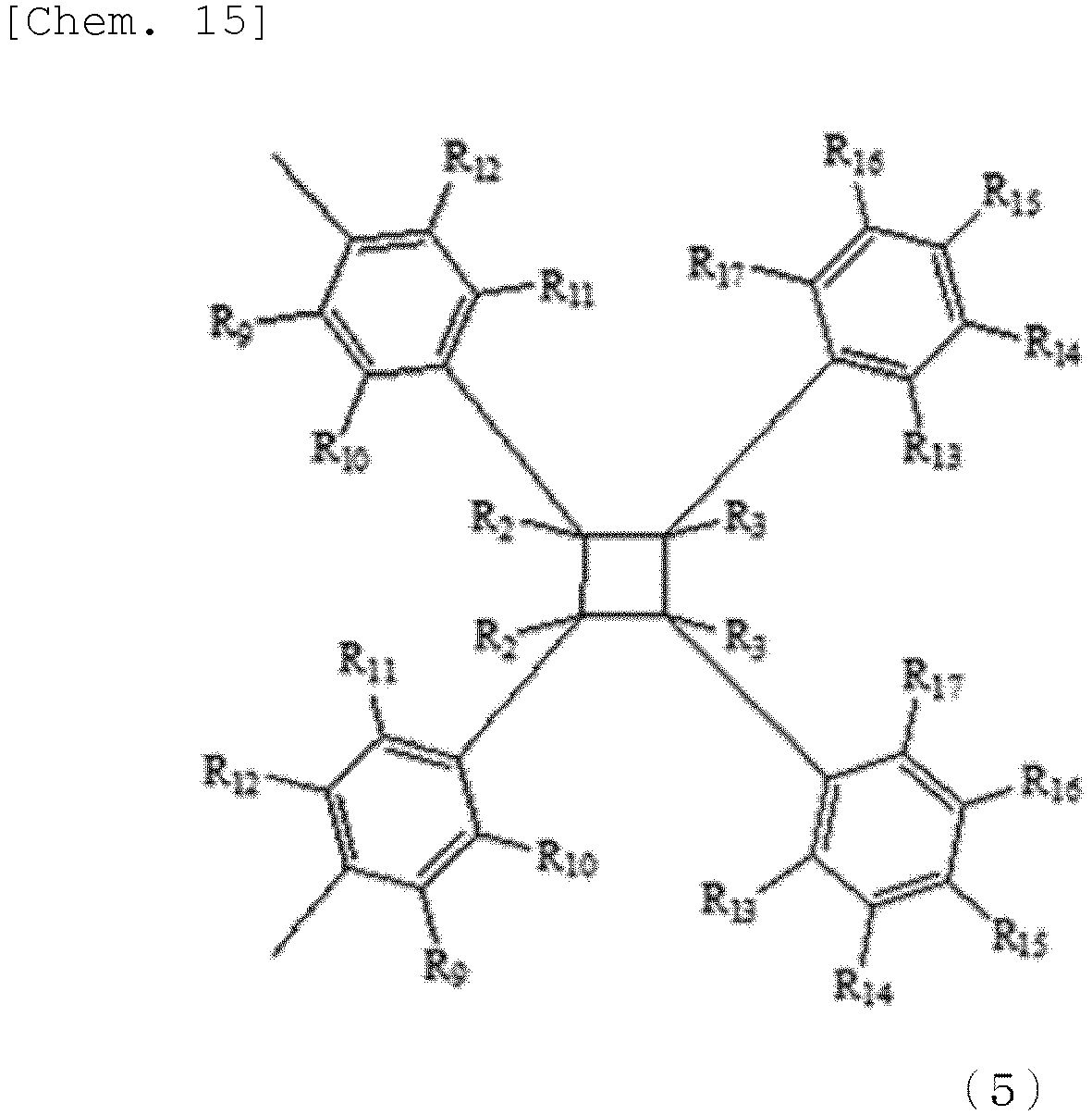
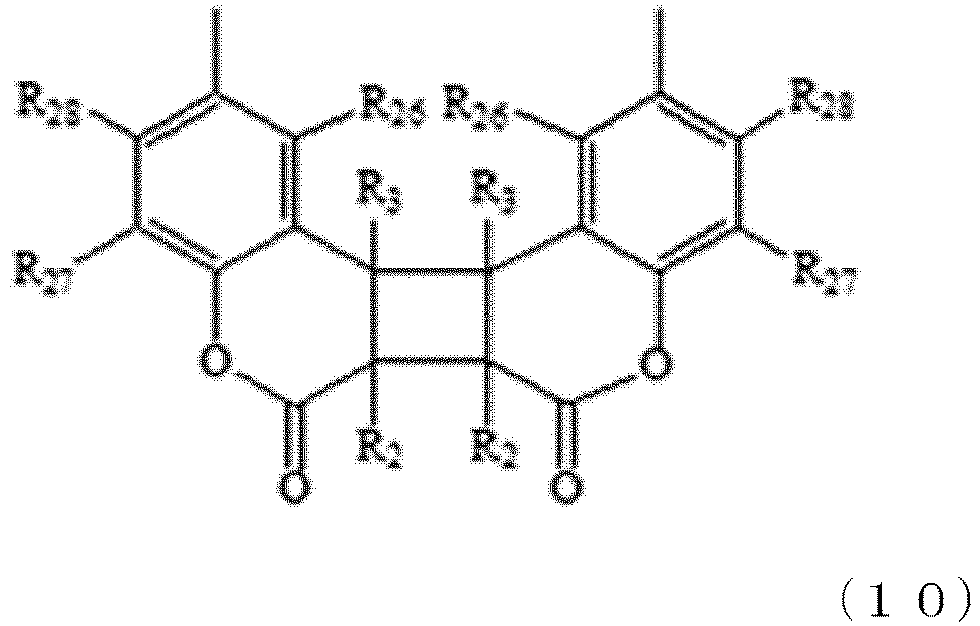
- Examples of the structure formed by cyclization of the photoreactive group includes the structures represented by Formulae (3) to (10) below.
- R 2 to R 28 are the same as those defined for Formulae (A) to (D).
- the resin including the repeating units represented by Formulae (1) and (2) may also contain a structure formed by dimerization of the photoreactive group, such as that shown below.
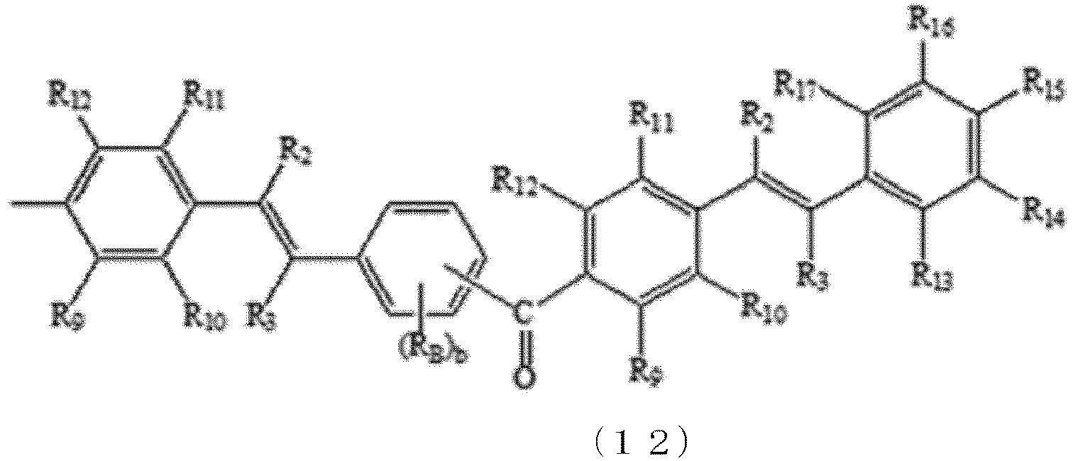
- Examples of the structure formed by dimerization of the photoreactive group includes the structures represented by Formulae (11) to (13) below.
- R 2 to R 25 are the same as those defined for Formulae (A) to (C)
- a, b, and c each represent an integer of 0 to 4
- R A represents a substituents selected from R 4 to R B as defined for Formula (A)
- R B represents b substituents selected from R 13 to R 17 as defined for Formula (B)
- R C represents c substituents selected from R 22 to R 25 as defined for Formula (C) .
- the resin of the present disclosure including the repeating units represented by Formulae (1) and (2) may further include an additional repeating unit other than the repeating units represented by Formulae (1) and (2) as long as the effect of the present disclosure is not impaired.
- additional repeating unit include butadiene, ethylene, propylene, acrylonitrile, alkyl acrylate, alkyl methacrylate, ⁇ -phenylalkyl acrylate, maleic anhydride, acrylic acid, 4-vinylpyridine, trans-1,3-pentadiene, p-acetoxystyrene, vinyltris(trimethoxysiloxy)silane, vinyl benzoate, vinyl butyl ether, and phenyl vinyl ketone, among which ethylene and propylene are preferred.
- the resin of the present disclosure including the repeating units represented by Formulae (1) and (2) may be produced by introducing a photocyclizable compound into an aromatic group-containing polymer through a Friedel-Crafts acylation reaction.
- the photocyclizable compound may be a cinnamic acid chloride compound represented by Formula (14) below, a phenylethenylbenzoic acid chloride compound represented by Formula (15) below, a pyridinylethenylbenzoic acid chloride compound represented by Formula (16) below, or a coumarin-6-carboxylic acid chloride compound represented by Formula (17) below, and is preferably a cinnamic acid chloride compound represented by Formula (14), which is easy to produce. Two or more of these compounds may also be used in combination as needed.
- R 2 to R 28 are the same as those defined for Formulae (A) to (D).
- the aromatic group-containing polymer into which the photoreactive group is to be introduced by the Friedel-Crafts acylation reaction may be any suitable type that is inert to the reaction catalyst described later.
- the aromatic group-containing polymer include polystyrenes, such as poly- ⁇ -methylstyrene, poly-p-methoxystyrene, and syndiotactic polystyrene; polyvinyl aryl ketones, such as polyvinylnaphthalene, polyvinylbiphenyl, polyvinylanthracene, polyvinylcarbazole, poly(vinyl phenyl ketone); styrenebutadiene copolymers; ethylene-styrene copolymers; ethylenepropylene-styrene copolymers; styrene-acrylonitrile copolymers; styrene-alkyl acrylate copolymers; styrene-
- the aromatic group-containing polymer is preferably a polymer made from only an aromatic hydrocarbon(s) and an aliphatic hydrocarbon(s), and examples of such a polymer include polystyrene, ethylene-styrene copolymers, and ethylenepropylene-styrene copolymers. Two or more of these copolymers may also be used in combination.
- the amount of the photocyclizable compound charged to the aromatic group-containing polymer into which the photoreactive group is introduced by the Friedel-Crafts acylation reaction is preferably 0.2 to 5.0 mol, more preferably 1.0 to 3.0 mol per mol of aromatic group contained in the aromatic group-containing polymer in order to improve the solubility of the resulting resin in organic solvents and the storage stability.
- the reaction catalyst is preferably a known superacid, examples of which include, but are not limited to, trifluoromethanesulfonic acid, fluorosulfonic acid, fluoroantimonic acid, and carborane acid.
- the reaction catalyst is preferably added in an amount of 0.1 to 3.0 moles to 1 mole of the photocyclizable compound.
- the Friedel-Crafts acylation reaction which is exothermic, may be accompanied by a side reaction to thermally crosslink the photoreactive group in the reaction system.
- the Friedel-Crafts acylation reaction is preferably carried out by solution reaction, during which the reaction temperature can be easily controlled.
- the solution reaction may be performed using any reaction solvent that is stable against the Friedel-Crafts reaction.
- the reaction solvent is preferably a sufficiently dehydrated (and thus inactive to the reaction) chlorinated hydrocarbon solvent, fluorinated solvent, aliphatic hydrocarbon solvent, sulfur-containing solvent, or nitrile solvent.
- chlorinated hydrocarbon solvent examples include methylene chloride, carbon tetrachloride, 1,1,2-trichloroethane, and chloroform.
- fluorinated solvent examples include ZEORORA H.
- aliphatic hydrocarbon solvent examples include cyclohexane.
- sulfur-containing solvent examples include carbon disulfide, sulfone dimethyl sulfoxide, dimethyl sulfate, and dimethyl sulfone.
- nitrile solvent examples include acetonitrile.
- the reaction temperature is preferably, but not limited to, 0 to 40°C in view of economy in cooling and heating. If necessary, the Friedel-Crafts acylation reaction may be carried out at a solvent reflux temperature, and such a temperature is preferably less than 200°C.
- reaction time is typically, but not limited to, 1 to 100 hours. In view of reaction rate and economy, the reaction time is preferably 2 to 20 hours.
- the resin of the present disclosure including the repeating units represented by Formulae (1) and (2) may be dissolved in a solvent, and the resulting solution may be applied or printed onto a variety of substrates to form a film.
- the solvent may be any type capable of dissolving the resin, examples of which include cyclohexane, aromatic hydrocarbons, such as benzene, toluene, xylene, ethylbenzene, isopropylbenzene, N-hexylbenzene, tetralin, decalin, isopropylbenzene, and chlorobenzene; chlorinated aliphatic hydrocarbon compounds, such as methylene chloride and 1,1,2-trichloroethylene; aliphatic cyclic ether compounds, such as tetrahydrofuran and dioxane; ketone compounds, such as methyl ethyl ketone, cyclopentanone, and cyclohexanone; ester compounds, such as ethyl acetate, dimethyl phthalate, methyl salicylate, amyl acetate, and 2-methoxy-1-methylethyl acetate; alcohols, such as n-butano
- the substrate examples include substrates of inorganic materials, such as glass, quartz, aluminum oxide, high-doped silicon, silicon oxide, tantalum dioxide, tantalum pentoxide, and indium tin oxide; plastics; metals, such as gold, copper, chromium, titanium, and aluminum; ceramics; coated paper; and surface-coated nonwoven fabrics.
- plastics include polyethylene terephthalate, polyethylene naphthalate, triacetyl cellulose, polycarbonate, polymethyl acrylate, polymethyl methacrylate, polyvinyl chloride, polyethylene, ethylene-vinyl acetate copolymers, polymethylpentene-1, polypropylene, cyclic polyolefin, fluorinated cyclic polyolefin, polystyrene, polyimide, polyvinyl phenol, polyvinyl alcohol, poly(diisopropyl fumarate), poly(diethyl fumarate), poly(diisopropyl maleate), polyether sulfone, polyphenylene sulfide, polyphenylene ether, polyester elastomers, polyurethane elastomers, polyolefin elastomers, polyamide elastomers, and styrene block copolymers.
- the resin of the present disclosure may be applied or printed onto the substrate, for example, by spin coating, drop casting, dip coating, doctor blade coating, pad printing, squeegee coating, roll coating, rod bar coating, air knife coating, wire bar coating, flow coating, gravure printing, flexographic printing, screen printing, inkjet printing, or reverse letterpress printing.
- the film of the present disclosure should be highly soluble in general-purpose solvents for the formation of the film of the present disclosure by these methods.
- the resin of the present disclosure including the repeating units represented by Formulae (1) and (2) may be used to form an insulating film.
- the resulting insulating film may be used as is, or if necessary, may be photocrosslinked (photocyclized) before use.
- the resin should be highly soluble in a general-purpose solvent for use in forming the insulating film, and an organic semiconductor layer should be able to be formed on top of the insulating film using a solvent different from the general-purpose solvent.
- the insulating film should have solvent resistance (crack resistance) against the organic semiconductor solution so that the insulating film can be used as is. If the resin does not have excellent solvent resistance (crack resistance), it is not possible to form a film by a printing method, and it is necessary to form a film by a method such as a vapor deposition method, which is less economical than a printing method.
- the insulating film including the resin of the present disclosure may be photocrosslinked (photocyclized) using a radiation, such as ultraviolet light with a wavelength of 245 to 350 nm.
- a radiation such as ultraviolet light with a wavelength of 245 to 350 nm.
- the irradiation dose is, for example, 50 to 3,000 mJ/cm 2 , preferably 50 to 1,000 mJ/cm 2 for the prevention of a reduction in cross-linking degree and for the process time reduction for higher economic efficiency, while it may be appropriately changed depending on the composition of the resin.
- the ultraviolet irradiation is usually performed in air. If necessary, the ultraviolet irradiation may be performed in an inert gas or under an inert gas stream at a constant rate. If necessary, a photosensitizing agent may be added to accelerate the photocrosslinking reaction.
- the photosensitizing agent may be any type, such as a benzophenone compound, an anthracene compound, an anthraquinone compound, a thioxanthone compound, or a nitrophenyl compound, among which a benzophenone compound is preferred, which have high compatibility with the resin of the present disclosure. Two or more of these sensitizers may be used in combination as needed.
- An insulating film containing the crosslinked resin of the present disclosure can be formed and used as a gate insulating layer in an organic field effect transistor device (OFET).
- OFET organic field effect transistor device
- the organic field-effect transistor device can be obtained, for example, by stacking, on a substrate, a gate electrode, a gate insulating layer, and an organic semiconductor layer provided with source and drain electrodes with the gate insulating layer interposed between the gate electrode and the semiconductor layer.
- the organic field-effect transistor device preferably has a mobility of 0.20 cm 2 /Vs or more in view of its practicality.
- the organic field-effect transistor device preferably has such a level of bias stress resistance that its threshold voltage will shift only by 2 V or less under application of a bias voltage for 1 hour.
- the organic field-effect transistor device may be any of a bottom-gate bottom-contact (BGBC) type, a bottom-gate top-contact (BGTC) type, a top-gate bottom-contact (TGBC) type, or a top-gate top-contact (TGTC) type.
- FIG. 1 shows the structure of one of organic field-effect transistor devices of these different structures, specifically the structure of a bottom-gate bottom-contact (BGBC) type device.
- the substrate for the OFET may be made of any material that can ensure a sufficiently flat surface for the fabrication of the device.
- the substrate may be a substrate of an inorganic material, such as glass, quartz, aluminum oxide, high-doped silicon, silicon oxide, tantalum dioxide, tantalum pentoxide, or indium tin oxide; a plastic substrate; a substrate of a metal, such as gold, copper, chromium, titanium, or aluminum; a ceramic substrate; a coated paper sheet; or a surface-coated nonwoven fabric.
- the substrate may also be a composite material including any combination of these materials or a multilayer material including layers of any of these materials.
- the surface of these materials may also be coated with a surface-tension modifying material.
- plastics used to form the substrate include polyethylene terephthalate, polyethylene naphthalate, triacetyl cellulose, polycarbonate, polymethyl acrylate, polymethyl methacrylate, polyvinyl chloride, polyethylene, ethylene-vinyl acetate copolymers, polymethylpentene-1, polypropylene, cyclic polyolefin, fluorinated cyclic polyolefin, polystyrene, polyimide, polyvinyl phenol, polyvinyl alcohol, poly(diisopropyl fumarate), poly(diethyl fumarate), poly(diisopropyl maleate), polyether sulfone, polyphenylene sulfide, polyphenylene ether, polyester elastomers, polyurethane elastomers, polyolefin elastomers, polyamide elastomers, and styrene block copolymers. Two or more of these plastic materials may be stacked to form
- the electrically conductive gate, source, or drain electrode may be made of, for example, gold, silver, aluminum, copper, titanium, platinum, chromium, polysilicon, silicide, indium tin oxide (ITO), tin oxide, or any other electrically conductive material. Two or more of these electrically conductive materials may be used to form a multilayer structure.
- the BGTC type device may have an electrode formed on the substrate or the organic semiconductor layer.
- the electrode may be formed by any suitable method, such as vapor deposition, high-frequency sputtering, or electron beam sputtering.
- nanoparticles of the electrically conductive material may be dissolved in water or an organic solvent to form an ink, and the electrode may be formed from the ink by solution spin coating, drop casting, dip coating, doctor blade coating, die coating, pad printing, roll coating, gravure printing, flexographic printing, screen printing, inkjet printing, reverse letterpress printing, or any other method.
- a treatment for adsorbing a fluoroalkylthiol or a fluoroarylthiol on the electrode may also be performed.
- any suitable raw material may be used to form the organic semiconductor layer.
- the organic semiconductor layer may include either of an N-type organic semiconductor and a P-type organic semiconductor.
- a combination of an N-type organic semiconductor and a p-type organic semiconductor may also be used to form a bipolar organic field-effect transistor device.
- Examples of the organic semiconductor include the compounds of Formulae (F-1) to (F-10) below.
- the compounds of Formulae (F-1) to (F-10) are preferred, and the compound of Formula (F-10) is particularly preferred.
- either of low-molecular-weight and high-molecular-weight organic semiconductors may be used.
- a mixture of these organic semiconductors may also be used.
- the organic semiconductor layer may be formed by any suitable method capable of forming a thin film layer of the organic semiconductor, such as a method of vapor-depositing the organic semiconductor under vacuum or a method of applying or printing a solution of the organic semiconductor in an organic solvent.
- concentration of the organic semiconductor in the solution to be applied or printed is preferably 0.2 to 5% by weight for the formation of a more uniform semiconductor layer with a reduced thickness while it depends on the structure of the organic semiconductor and the solvent used.
- the organic solvent may be any type capable of dissolving the organic semiconductor at a certain concentration to enable film formation.
- organic solvent examples include hexane, heptane, octane, decane, dodecane, tetradecane, decalin, indane, 1-methylnaphthalene, 2-ethylnaphthalene, 1,4-dimethylnaphthalene, a mixture of dimethylnaphthalene isomers, toluene, xylene, ethylbenzene, 1,2,4-trimethylbenzene, mesitylene, isopropylbenzene, pentylbenzene, hexylbenzene, tetralin, octylbenzene, cyclohexylbenzene, 1,2-dichlorobenzene, 1,3-dichlorobenzene, 1,4-dichlorobenzene, trichlorobenzene, 1,2-dimethoxybenzene, 1,3-dimethoxybenzene, ⁇ -butyrolactone, 1,
- an organic solvent having a high organic semiconductor-dissolving power and a boiling point of 100°C or more is appropriate, such as toluene, xylene, isopropylbenzene, anisole, cyclohexanone, mesitylene, 1,2-dichlorobenzene, 3,4-dimethylanisole, pentylbenzene, tetralin, cyclohexylbenzene, or decahydro-2-naphthol.
- a mixed solvent of two or more of these solvents in an appropriate proportion may also be used.
- any of various organic or inorganic polymers or oligomers or organic or inorganic nanoparticles may be added in the form of a solid or an organic solvent dispersion to form the organic semiconductor layer.
- a polymer solution may also be applied onto the gate insulating layer to form a protective film. If necessary, various types of moisture-proof coating or light-resistant coating may also be performed on the protective film.
- the organic semiconductor (di-n-hexyldithienobenzodithiophene) used in the examples was synthesized according to the production method disclosed in Japanese Unexamined Patent Application, Publication No. 2015-224238 .
- NMR magnetic resonance
- spin coating film thickness measurement
- ultraviolet (UV) irradiation ultraviolet irradiation
- vacuum deposition evaluation of the transfer characteristics and bias stress resistance of OFET devices were performed using the conditions and systems shown below.
- the 1 H-NMR spectrum measurement was performed using JNM-ECZ400S FT-NMR (manufactured by JEOL Ltd.).
- the spin coater used was MS-A100 manufactured by Mikasa Co., Ltd.
- the film thickness was measured using Dektak XT Stylus Profiler manufactured by Bruker Corporation.
- UV irradiation was performed under conditions at a UV dose of 14.2 mW/cm 2 using UV Mask Aligner UPE-1605MA manufactured by Ushio Lighting, Inc.
- the vacuum deposition was performed using a compact vacuum deposition system VTR-350M/ERH manufactured by ULVAC Kikou Inc.
- a bottom-gate bottom-contact (BGBC) type organic field-effect transistor device was prepared and measured for transfer characteristics (Id-Vg) before bias voltage application.
- the measurement was performed through gate voltage (Vg) scanning using Semiconductor Parameter Analyzer 4200-SCS (manufactured by Keithley Instruments) with a source-drain voltage (Vd) of -15V in the BGBC type FET device.
- Vd source-drain voltage
- Vd source-drain voltage
- Resins 1 to 9 were synthesized as shown below. During the synthesis, the reaction, the purification, and the drying were all performed under yellow light or in the dark. The reason to conduct the synthesis under yellow light or in the dark was to prevent the photocyclization reaction of the photocyclizable compound and to prevent the photocyclization reaction of the resin resulting from the introduction of the photocyclizable compound.
- the mixture was stirred in ice bath for 1 hour and then allowed to react at room temperature for 5 hours.
- the solution resulting from the reaction was fed through a cannula to a saturated sodium hydrogen carbonate aqueous solution for neutralization of trifluoromethanesulfonic acid and hydrochloric acid in the system.
- the aqueous layer of the neutralized solution was removed by decantation, and the dichloromethane layer was separated. The process of adding water to the dichloromethane layer and removing the aqueous layer by decantation was performed twice to remove the excess of sodium hydrogen carbonate.
- the resulting resin 1 (of the formula below) was confirmed to include 21 mol% of the repeating unit represented by Formula (1) and 79 mol% of the repeating unit represented by Formula (2).
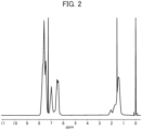
- the 1 H-NMR chart of resin 1 is shown in FIG. 2 .
- a 50 nm-thick gate electrode was formed by vacuum deposition of silver on a cleaned, dried glass (substrate) of 30 mm ⁇ 30 mm (Eagle XG manufactured by Corning Incorporated).
- a solution of resin 1 (11 wt%) in 2-methoxy-1-methylethyl acetate was applied onto the electrode-carrying substrate by spin coating under the conditions of 500 rpm for 5 seconds and 2,000 rpm for 20 seconds and then dried at 50°C for 1 minute (to form an insulating film).
- the resulting film was irradiated with 100 mJ/cm 2 of ultraviolet rays to form a 500 nm-thick, crosslinked, gate insulating layer.
- Source and drain electrodes with a thickness of 50 nm, a channel length of 100 um, and a width of 500 um were formed by vacuum deposition of gold on the substrate having the gate electrode and the gate insulating layer.
- the substrate was immersed in an isopropanol solution of 30 mmol of pentafluorobenzenethiol, removed after 5 minutes from the solution, washed with isopropanol, and dried by blowing air.
- An organic semiconductor layer was then formed on the substrate by a drop casting process including: dropping 220 ⁇ L of a toluene solution of 0.8 wt% of an organic semiconductor (di-n-hexyldithienobenzodithiophene) on the substrate; allowing the drop on the substrate to stand for 15 hours in a dark thermostatic chamber; and heating the drop on the substrate at 40°C for 3 hours to volatilize the solvent.
- BGBC bottom-gate bottom-contact
- Table 1 shows the HOMO level of the repeating unit represented by Formula (2) in the synthesized resin, the mobility of the resulting organic field-effect transistor device, and the result of evaluation of its bias stress resistance.
- Resin HOMO level of repeating unit of Formula (2) Transfer characteristics Bias stress resistance Mobility Change in threshold voltage before and after bias stress [eV] [cm 2 /V ⁇ s] [
- Example 1 -6.62 0.23 1.0 2 -6.58 0.20 1.4 3 -6.65 0.32 0.2 4 -6.85 0.32 0.2 5 -6.76 0.24 0.4 6 -6.83 0.35 1.6 7 -6.43 0.21 1.8
- Comparative Example 8 -6.27 0.10 5.5 9 -6.09 0.05 4.0
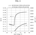
- FIG. 3 shows the transfer characteristics before and after the bias stress application.
- Resin 2 was obtained in an amount of 4.3 g (89% yield) in the same manner as in Example 1 except that 3-(trifluoromethyl)cinnamic acid was replaced with 2-(trifluoromethyl)cinnamic acid (manufactured by Tokyo Chemical Industry Co., Ltd.).
- the resulting resin 2 (of the formula below) was confirmed to include 26 mol% of the repeating unit represented by Formula (1) and 74 mol% of the repeating unit represented by Formula (2).
- An insulating film and an organic field-effect transistor device were formed in the same manner as in Example 1 except that the resulting resin 2 was used instead and the UV irradiation dose was changed to 500 mJ/cm 2 .
- the transfer characteristics were evaluated in the same manner as in the case of resin 1.
- the organic field-effect transistor device showed a mobility of 0.20 cm 2 /V ⁇ s, and the change in threshold voltage before and after the bias stress application was 1.4 V, which indicated high mobility and high bias stress resistance.
- the evaluation results are also shown in Table 1.
- Resin 3 was obtained in an amount of 3.8 g (72% yield) in the same manner as in Example 1 except that 3-(trifluoromethyl)cinnamic acid was replaced with 4-(trifluoromethyl)cinnamic acid (Tokyo Chemical Industry Co., Ltd.).
- the resulting resin 3 (of the formula below) was confirmed to include 14 mol% of the repeating unit represented by Formula (1) and 86 mol% of the repeating unit represented by Formula (2).
- Resin 4 was obtained in an amount of 4.0 g (80% yield) in the same manner as in Example 1 except that 3-(trifluoromethyl)cinnamic acid was replaced with trans-3,5-bis(trifluoromethyl)cinnamic acid (manufactured by Apollo Scientific) and that the amount of trifluoromethanesulfonic acid was changed to 7.2 g (48 mmol).
- the resulting resin 4 (of the formula below) was confirmed to include 22 mol% of the repeating unit represented by Formula (1) and 78 mol% of the repeating unit represented by Formula (2).
- An insulating film and an organic field-effect transistor device were formed in the same manner as in Example 1 except that the resulting resin 4 was used instead and the solution concentration was changed to 12 wt%.
- the transfer characteristics were evaluated in the same manner as in the case of resin 1.
- the organic field-effect transistor device showed a mobility of 0.32 cm 2 /V ⁇ s, and the change in threshold voltage before and after the bias stress application was 0.2 V, which indicated high mobility and high bias stress resistance.
- the evaluation results are also shown in Table 1.
- Resin 5 was obtained in an amount of 3.0 g (53% yield) in the same manner as in Example 1 except that 3-(trifluoromethyl)cinnamic acid was replaced with 2,3,4,5,6-pentafluorocinnamic acid (manufactured by Tokyo Chemical Industry Co., Ltd.).
- the resulting resin 5 (of the formula below) was confirmed to include 13 mol% of the repeating unit represented by Formula (1) and 87 mol% of the repeating unit represented by Formula (2).
- An insulating film and an organic field-effect transistor device were formed in the same manner as in Example 1 except that the resulting resin 5 was used instead and the UV irradiation dose was changed to 200 mJ/cm 2 .
- the transfer characteristics were evaluated in the same manner as in the case of resin 1.
- the organic field-effect transistor device showed a mobility of 0.24 cm 2 /V ⁇ s, and the change in threshold voltage was 0.4 V, which indicated high mobility and high bias stress resistance.
- the evaluation results are also shown in Table 1.
- Resin 6 was obtained in an amount of 4.0 g (80% yield) in the same manner as in Example 1 except that 3-(trifluoromethyl)cinnamic acid was replaced with 3-nitrocinnamic acid (manufactured by Tokyo Chemical Industry Co., Ltd.).
- the resulting resin 6 (of the formula below) was confirmed to include 57 mol% of the repeating unit represented by Formula (1) and 43 mol% of the repeating unit represented by Formula (2).
- Resin 7 was obtained in an amount of 3.7 g (82% yield) in the same manner as in Example 1 except that 3-(trifluoromethyl)cinnamic acid was replaced with 3-fluorocinnamic acid (manufactured by Tokyo Chemical Industry Co., Ltd.).
- the resulting resin 7 (of the formula below) was confirmed to include 23 mol% of the repeating unit represented by Formula (1) and 77 mol% of the repeating unit represented by Formula (2).
- the resulting resin 8 (of the formula below) was confirmed to include 17 mol% of the repeating unit represented by Formula (1) and 83 mol% of the repeating unit represented by Formula (2).
- Example 1 An insulating film and an organic field-effect transistor device were formed in the same manner as in Example 1 except that the resulting resin 8 was used instead.
- the transfer characteristics were evaluated in the same manner as in the case of resin 1.
- the organic field-effect transistor device showed a mobility of 0.10 cm 2 /V ⁇ s, and the change in threshold voltage was 5.5 V, which indicated lower mobility and lower bias stress resistance than Examples 1 to 7.
- Table 1 shows the features of the prepared organic field-effect transistor device and the evaluation results.
- Resin 9 was obtained in an amount of 4.0 g (70% yield) in the same manner as in Example 1 except that 3-(trifluoromethyl)cinnamic acid was replaced with 4-methylcinnamic acid (manufactured by Tokyo Chemical Industry Co., Ltd.).
- the resulting resin 9 (of the formula below) was confirmed to include 6 mol% of the repeating unit represented by Formula (1) and 94 mol% of the repeating unit represented by Formula (2).
- An insulating film and an organic field-effect transistor device were formed in the same manner as in Example 1 except that the resulting resin 9 was used instead and the UV irradiation dose was changed to 1,000 mJ/cm 2 .
- the transfer characteristics were evaluated in the same manner as in the case of resin 1.
- the organic field-effect transistor device showed a mobility of 0.05 cm 2 /V ⁇ s, and the change in threshold voltage was 4.0 V, which indicated lower mobility and lower bias stress resistance than Examples 1 to 7.
- Table 1 shows the features of the prepared organic field-effect transistor device and the evaluation results.
- the organic field-effect transistor of each of Examples 1 to 7 prepared using the resin including the repeating unit of Formula (2) with a HOMO level of at most -6.4 eV exhibits higher mobility and higher bias stress resistance than that of Comparative Example 1 or 2 prepared using the resin including the repeating unit of Formula (2) with a HOMO level of more than -6.4 eV.
Landscapes
- Chemical & Material Sciences (AREA)
- Organic Chemistry (AREA)
- Health & Medical Sciences (AREA)
- Chemical Kinetics & Catalysis (AREA)
- Medicinal Chemistry (AREA)
- Polymers & Plastics (AREA)
- General Chemical & Material Sciences (AREA)
- Engineering & Computer Science (AREA)
- Materials Engineering (AREA)
- Manufacturing & Machinery (AREA)
- Life Sciences & Earth Sciences (AREA)
- Wood Science & Technology (AREA)
- Emergency Medicine (AREA)
- Addition Polymer Or Copolymer, Post-Treatments, Or Chemical Modifications (AREA)
- Thin Film Transistor (AREA)
- Formation Of Insulating Films (AREA)
- Electroluminescent Light Sources (AREA)
Abstract
Description
- The present disclosure relates to a resin for forming gate insulating film layers suitable for organic field-effect transistor devices with high bias stress resistance.
- Organic field-effect transistor devices, which can be manufactured through film-forming methods including application or printing of organic material-containing solutions, have attracted attention for their potential to be manufactured in a large number on a large-area substrate at a low cost.
- As a polymer dielectric layer (insulating film layer) used in organic field effect transistor devices, a technique using a photocrosslinkable polymer in which a compound having a photocrosslinkable group is introduced into an aromatic vinyl polymer such as polystyrene or poly-α-methylstyrene by a Friedel-Crafts acylation reaction has been disclosed (see, for example, Patent Document 1).
- In recent years, such polymer dielectric layers have been required to have higher bias stress resistance for reliability and stability of organic field-effect transistor devices. It is generally known that under application of a constant bias voltage for a long time, organic field-effect transistor devices will change their threshold voltage. Such bias stress-induced changes in threshold voltage should preferably be at most 2 V. Such changes may be attributed to various causes including environmental factors, such as oxidation by the air and water from the air, and other factors, such as organic semiconductor crystal structure and defects, among which one of the main factors may be carrier trapping, which is a phenomenon in which after being generated in semiconductor layers, carriers are trapped in polymer dielectric layers (insulating film layers) (see, for example, Non-Patent Document 1).
- Patent Document 1:
Japanese Unexamined Patent Application, Publication No. 2018-154814 - Non-Patent Document 1: Advanced Materials, Vol. 26, p. 1660 (2014)
- As a result of research, the inventors have found that recent organic field-effect transistor devices have been required to have bias stress resistance higher than that of the organic field-effect transistor device having a gate insulating film layer of the resin disclosed in
Patent Document 1. - It is an object of the present disclosure, which has been made in view of the problem described above, to provide a resin for forming gate insulating film layers suitable for organic field-effect transistor devices with high bias stress resistance.
- As a result of intensive studies, the inventors have completed the present disclosure based on findings that by deepening the HOMO level of the resin (insulating film layer),the energy barrier when carriers generated in the organic semiconductor layer are captured by the resin increases, as a result, carrier traps are suppressed, which is effective in improving mobility and bias stress resistance, and certain resins have excellent mobility and bias stress resistance required for insulating films.
- Specifically, the present disclosure has the following gist.
-
- [1] A resin including: a repeating unit represented by Formula (1); and a repeating unit represented by Formula (2), the repeating unit represented by Formula (2) having a HOMO level of -6.4 eV or less, the resin containing 20 mol% or more of the repeating unit represented by Formula (2) based on the total moles of the repeating unit represented by Formula (1) and the repeating unit represented by Formula (2),


- [2] The resin according to [1], wherein the repeating unit represented by Formula (2) has at least one selected from the group consisting of a halogen atom, a cyano group, a nitro group, a carboxyalkyl group, and a fluoroalkyl group.
- [3] An insulating film including a crosslinked product of the resin according to [1] or [2].
- [4] In an organic field effect transistor device in which an organic semiconductor layer having a source electrode and a drain electrode and a gate electrode are laminated on a substrate with a gate insulating layer interposed therebetween, an organic field effect transistor device, characterized in that the gate insulating layer is the insulating film according to [3].
- The present disclosure provides a resin for forming gate insulating film layers suitable for organic field-effect transistor devices with high bias stress resistance.
-
-
FIG. 1 is a view of a cross-sectional shape of a bottom-gate bottom-contact (BGBC) type device; -
FIG. 2 is a diagram showing a 1H-NMR chart ofresin 1 produced in Example 1; -
FIG. 3 is a graph showing that an OFET device produced in Example 1 suffers from a minor change in transfer characteristics (Id-Vg) before and after continuous application of a gate voltage (Vg) of -30 V for 1 hour and thus has high bias stress resistance; and -
FIG. 4 is a graph showing that an OFET device produced in Comparative Example 1 suffers from a significant change in transfer characteristics (Id-Vg) before and after continuous application of a gate voltage (Vg) of -30 V for 1 hour. - Hereinafter, the present disclosure will be described in detail.
- The resin of the present disclosure includes the repeating unit represented by Formula (1) and the repeating unit represented by Formula (2).
- In Formula (1), R1 represents a hydrogen atom or a C1-C6 alkyl group, and preferably represents a hydrogen atom.
- Examples of the C1-C6 alkyl group for R1 in Formula (1) include, but are not limited to, a methyl group, an ethyl group, an n-propyl group, an isopropyl group, and an n-butyl group.
- In Formula (1), S1 represents -O- or -C(O)-.
- In Formula (1), p represents 0 or 1, and preferably represents 0.
- In Formula (1), A1 represents a C6-C19 aryl group.
- Examples of the C6-C19 aryl group for A1 in Formula (1) include, but are not limited to, a phenyl group, a naphthyl group, an anthryl group, and a biphenyl group, among which a phenyl group is preferred.
- In Formula (1), Y represents a halogen atom, a cyano group, a nitro group, a carboxyalkyl group, an alkyl ether group, an aryl ether group, a C1-C18 alkyl group, a fluoroalkyl group, or a cycloalkyl group.
- Examples of the halogen atom for Y in Formula (1) include, but are not limited to, a chlorine atom, a fluorine atom, and a bromine atom.
- Examples of the carboxyalkyl group for Y in Formula (1) include, but are not limited to, a carboxymethyl group (-COOCH3), a carboxyethyl group (-COOCH2CH3), and a carboxypropyl group (-COOCH2CH2CH3) .
- Examples of the alkyl ether group for Y in Formula (1) include, but are not limited to, a methoxy group, an ethoxy group, an n-propoxy group, an isopropoxy group, and a butoxy group.
- Examples of the aryl ether group for Y in Formula (1) include, but are not limited to, a phenoxy group, a p-methylphenoxy group, a p-ethylphenoxy group, and a p-methoxyphenoxy group.
- Examples of the C1-C18 alkyl group for Y in Formula (1) include, but are not limited to, a methyl group, an ethyl group, an n-propyl group, an isopropyl group, and an n-butyl group.
- Examples of the fluoroalkyl group for Y in Formula (1) include, but are not limited to, a 1,1,1-trifluoroethyl group, a 1,1,1,2,2-pentafluoropropyl group, a 1,1,1,2,2,3,3-heptafluorobutyl group, a trifluoromethyl group, and a pentafluoroethyl group.
- Examples of the cycloalkyl group for Y in Formula (1) include, but are not limited to, a cyclobutyl group, a cyclopentyl group, and a cyclohexyl group.
- In Formula (1), k represents an integer of 0 to (s-1), and preferably represents 0, wherein s represents the number of carbon atoms in A1.
- In Formula (2), R2A represents a hydrogen atom or a C1-C6 alkyl group, and preferably represents a hydrogen atom.
- Examples of the C1-C6 alkyl group for R2A in Formula (2) include, but are not limited to, a methyl group, an ethyl group, an n-propyl group, an isopropyl group, and an n-butyl group.
- In Formula (2), S2 represents -O- or -C(O)-.
- In Formula (2), q represents 0 or 1, and preferably represents 0.
- In Formula (2), A2 represents a C6-C19 aryl group.
- Examples of the C6-C19 aryl group for A2 in Formula (2) include, but are not limited to, a phenyl group, a naphthyl group, an anthranil group, and a biphenyl group, among which a phenyl group is preferred.
- In Formula (2), Y represents the same substituent as defined for Formula (1).
- In Formula (2), m represents an integer of 1 to (r - j - 1), r represents the number of carbon atoms in A2, and j represents an integer of 0 to (r - 2). m is preferably 1, and j is preferably 0.
- In Formula (2), Z represents at least one organic group selected from the group consisting of organic groups represented by Formulae (A) to (D), and preferably represents an organic group represented by Formula (A).
- In formulae (A) to (D), R2 and R2 each independently represent a hydrogen atom, a halogen atom, a C1-C6 alkyl group, an aryl group, or a carboxyalkyl group, preferably each independently represent a hydrogen atom, a halogen atom, or a C1-C6 alkyl group, and more preferably each independently represent a hydrogen atom; R4 to R28 each independently represent a hydrogen atom, a halogen atom, a cyano group, a nitro group, a carboxyalkyl group, an alkyl ether group, an aryl ether group, a C1-C18 alkyl group, a fluoroalkyl group, or a cycloalkyl group, preferably each independently represent a halogen atom, a cyano group, a nitro group, a carboxyalkyl group, or a fluoroalkyl group, and more preferably each independently represent a halogen atom, a nitro group, or a fluoroalkyl group.
- Examples of the halogen atom for R2 and R2 in Formulae (A) to (D) include, but are not limited to, a chlorine atom, a fluorine atom, and a bromine atom.
- Examples of the C1-C6 alkyl group for R2 and R3 in Formulae (A) to (D) include, but are not limited to, a methyl group, an ethyl group, an n-propyl group, an isopropyl group, and an n-butyl group.
- Examples of the aryl group for R2 and R3 in Formulae (A) to (D) include, but are not limited to, a phenyl group, a naphthyl group, an anthryl group, and a biphenyl group.
- Examples of the carboxyalkyl group for R2 and R3 in Formulae (A) to (D) include, but are not limited to, a carboxymethyl group (-COOCH3), a carboxyethyl group (-COOCH2CH3), and a carboxypropyl group (-COOCH2CH2CH3) .
- Examples of the halogen atom for R4 to R28 in Formulae (A) to (D) include, but are not limited to, a chlorine atom, a fluorine atom, and a bromine atom, among which a chlorine atom and a fluorine atom are preferred.
- Examples of the carboxyalkyl group for R4 to R28 in Formulae (A) to (D) include, but are not limited to, a carboxymethyl group (-COOCH3), a carboxyethyl group (-COOCH2CH3), and a carboxypropyl group (-COOCH2CH2CH3) .
- Examples of the alkyl ether group for R4 to R28 in Formulae (A) to (D) include, but are not limited to, a methoxy group, an ethoxy group, an n-propoxy group, an isopropoxy group, and a butoxy group.
- Examples of the aryl ether group for R4 to R28 in Formulae (A) to (D) include, but are not limited to, a phenoxy group, a p-methylphenoxy group, a p-ethylphenoxy group, and a p-methoxyphenoxy group.
- Examples of the C1-C18 alkyl group for R4 to R28 in Formulae (A) to (D) include, but are not limited to, a methyl group, an ethyl group, an n-propyl group, an isopropyl group, an n-butyl group, an n-hexyl group, an n-decyl group, and an n-octadecyl group.
- Examples of the fluoroalkyl group for R4 to R28 in Formulae (A) to (D) include, but are not limited to, a 1,1,1-trifluoroethyl group, a 1,1,1,2,2-pentafluoropropyl group, a 1,1,1,2,2,3,3-heptafluorobutyl group, a trifluoromethyl group, and a pentafluoroethyl group, among which a trifluoromethyl group is preferred.
- Examples of the cycloalkyl group for R4 to R28 in Formulae (A) to (D) include, but are not limited to, a cyclobutyl group, a cyclopentyl group, and a cyclohexyl group.
- Examples of the organic group represented by Formula (A) include those shown below.

- Among them, the organic groups shown below are preferred.

- The organic groups shown below are particularly preferred.


- Examples of the organic group represented by Formula (B) include those shown below.


- Examples of the organic group represented by Formula (C) include those shown below.

- Examples of the organic group represented by Formula (D) include those shown below.

- In the resin of the present disclosure, the repeating unit represented by Formula (2) has a HOMO level of -6.4 eV or less, preferably -6.5 eV or less, more preferably -7.00 to - 6.5 eV.
- In general, the term "HOMO level" means an orbital energy level of a single molecule. In the description, however, the HOMO level of the repeating unit is defined as the HOMO level of a compound derived from the repeating unit by substituting the ends of the repeating unit with hydrogen atoms.
- In the description, the HOMO energy level is the value calculated using the quantum chemical calculation program Gaussian. The calculation conditions include the following: B3LYP (atomic orbital density functional); 6-31G (d, p) (base function); and Gaussian 09W (program used).
- For ease of having a HOMO level of -6.4 eV or less, the repeating unit represented by Formula (2) preferably has at least one selected from the group consisting of a halogen atom, a cyano group, a nitro group, a carboxyalkyl group, and a fluoroalkyl group.
- The resin of the present disclosure including the repeating units represented by Formulae (1) and (2) contains 20 mol% or more, preferably 40 mol% or more, more preferably 70 mol% or more of the repeating unit represented by Formula (2) based on the total moles of the repeating units represented by Formulae (1) and (2).
- In the present disclosure, the molecular weight of the resin including the repeating units represented by Formulae (1) and (2) is typically, but not limited to, 200 to 10,000,000 (g/mole). In view of the viscosity of the resulting resin solution and the mechanical strength of the resin, the molecular weight of the resin is preferably 10,000 to 1,000,000 (g/mole).
- The resin including the repeating units represented by Formulae (1) and (2) may have a structure formed by cyclization of a photoreactive group in the polymer molecule as long as the solubility is not impaired.
- Examples of the structure formed by cyclization of the photoreactive group includes the structures represented by Formulae (3) to (10) below.




- The resin including the repeating units represented by Formulae (1) and (2) may also contain a structure formed by dimerization of the photoreactive group, such as that shown below.
- Examples of the structure formed by dimerization of the photoreactive group includes the structures represented by Formulae (11) to (13) below.



- The resin of the present disclosure including the repeating units represented by Formulae (1) and (2) may further include an additional repeating unit other than the repeating units represented by Formulae (1) and (2) as long as the effect of the present disclosure is not impaired. Examples of such an additional repeating unit include butadiene, ethylene, propylene, acrylonitrile, alkyl acrylate, alkyl methacrylate, α-phenylalkyl acrylate, maleic anhydride, acrylic acid, 4-vinylpyridine, trans-1,3-pentadiene, p-acetoxystyrene, vinyltris(trimethoxysiloxy)silane, vinyl benzoate, vinyl butyl ether, and phenyl vinyl ketone, among which ethylene and propylene are preferred.
- The resin of the present disclosure including the repeating units represented by Formulae (1) and (2) may be produced by introducing a photocyclizable compound into an aromatic group-containing polymer through a Friedel-Crafts acylation reaction.
- In the present disclosure, the photocyclizable compound may be a cinnamic acid chloride compound represented by Formula (14) below, a phenylethenylbenzoic acid chloride compound represented by Formula (15) below, a pyridinylethenylbenzoic acid chloride compound represented by Formula (16) below, or a coumarin-6-carboxylic acid chloride compound represented by Formula (17) below, and is preferably a cinnamic acid chloride compound represented by Formula (14), which is easy to produce. Two or more of these compounds may also be used in combination as needed.


- The aromatic group-containing polymer into which the photoreactive group is to be introduced by the Friedel-Crafts acylation reaction may be any suitable type that is inert to the reaction catalyst described later. Examples of the aromatic group-containing polymer include polystyrenes, such as poly-α-methylstyrene, poly-p-methoxystyrene, and syndiotactic polystyrene; polyvinyl aryl ketones, such as polyvinylnaphthalene, polyvinylbiphenyl, polyvinylanthracene, polyvinylcarbazole, poly(vinyl phenyl ketone); styrenebutadiene copolymers; ethylene-styrene copolymers; ethylenepropylene-styrene copolymers; styrene-acrylonitrile copolymers; styrene-alkyl acrylate copolymers; styrene-alkyl methacrylate copolymers; styrene-α-phenylalkyl acrylate copolymers; styrene-maleic anhydride copolymers; styrene-acrylic acid copolymers; styrene-4-vinylpyridine copolymers; styrene-trans-1,3-pentadiene copolymers; styrene-2,4,6-trimethylstyrene copolymers; styrene-p-acetoxystyrene copolymers; styrene-vinyltris(trimethoxysiloxy)silane copolymers; styrene-vinyl benzoate copolymers; styrene-vinyl butyl ether copolymers; poly(aryl vinyl ketone), such as poly(phenyl vinyl ketone); and petroleum resins. For a reduction in permittivity and a reduction in current leakage, the aromatic group-containing polymer is preferably a polymer made from only an aromatic hydrocarbon(s) and an aliphatic hydrocarbon(s), and examples of such a polymer include polystyrene, ethylene-styrene copolymers, and ethylenepropylene-styrene copolymers. Two or more of these copolymers may also be used in combination.
- The amount of the photocyclizable compound charged to the aromatic group-containing polymer into which the photoreactive group is introduced by the Friedel-Crafts acylation reaction is preferably 0.2 to 5.0 mol, more preferably 1.0 to 3.0 mol per mol of aromatic group contained in the aromatic group-containing polymer in order to improve the solubility of the resulting resin in organic solvents and the storage stability. In view of solubility in organic solvents, storage stability, and high photocrosslinkability, and in view of solvent resistance (crack resistance) of the photocrosslinked resin layer, the amount of the photoreactive group to be introduced into the aromatic group by the reaction is preferably 0.2 to 1.0 mole, more preferably 0.4 to 1.0 mole, based on 1 mole of the aromatic group in the resin.
- The Friedel-Crafts acylation reaction may be carried out using a reaction catalyst.
- In the present disclosure, the reaction catalyst is preferably a known superacid, examples of which include, but are not limited to, trifluoromethanesulfonic acid, fluorosulfonic acid, fluoroantimonic acid, and carborane acid. In order to prevent reaction rate reduction and avoid complicated neutralization process after the reaction, the reaction catalyst is preferably added in an amount of 0.1 to 3.0 moles to 1 mole of the photocyclizable compound.
- The Friedel-Crafts acylation reaction, which is exothermic, may be accompanied by a side reaction to thermally crosslink the photoreactive group in the reaction system. In the present disclosure, therefore, for the prevention of such a side reaction, the Friedel-Crafts acylation reaction is preferably carried out by solution reaction, during which the reaction temperature can be easily controlled. In the present disclosure, the solution reaction may be performed using any reaction solvent that is stable against the Friedel-Crafts reaction. The reaction solvent is preferably a sufficiently dehydrated (and thus inactive to the reaction) chlorinated hydrocarbon solvent, fluorinated solvent, aliphatic hydrocarbon solvent, sulfur-containing solvent, or nitrile solvent. Examples of the chlorinated hydrocarbon solvent include methylene chloride, carbon tetrachloride, 1,1,2-trichloroethane, and chloroform. Examples of the fluorinated solvent include ZEORORA H. Examples of the aliphatic hydrocarbon solvent include cyclohexane. Examples of the sulfur-containing solvent include carbon disulfide, sulfone dimethyl sulfoxide, dimethyl sulfate, and dimethyl sulfone. Examples of the nitrile solvent include acetonitrile.
- In the Friedel-Crafts acylation reaction, the reaction temperature is preferably, but not limited to, 0 to 40°C in view of economy in cooling and heating. If necessary, the Friedel-Crafts acylation reaction may be carried out at a solvent reflux temperature, and such a temperature is preferably less than 200°C.
- In the Friedel-Crafts acylation reaction, the reaction time is typically, but not limited to, 1 to 100 hours. In view of reaction rate and economy, the reaction time is preferably 2 to 20 hours.
- The resin of the present disclosure including the repeating units represented by Formulae (1) and (2) may be dissolved in a solvent, and the resulting solution may be applied or printed onto a variety of substrates to form a film.
- The solvent may be any type capable of dissolving the resin, examples of which include cyclohexane, aromatic hydrocarbons, such as benzene, toluene, xylene, ethylbenzene, isopropylbenzene, N-hexylbenzene, tetralin, decalin, isopropylbenzene, and chlorobenzene; chlorinated aliphatic hydrocarbon compounds, such as methylene chloride and 1,1,2-trichloroethylene; aliphatic cyclic ether compounds, such as tetrahydrofuran and dioxane; ketone compounds, such as methyl ethyl ketone, cyclopentanone, and cyclohexanone; ester compounds, such as ethyl acetate, dimethyl phthalate, methyl salicylate, amyl acetate, and 2-methoxy-1-methylethyl acetate; alcohols, such as n-butanol, ethanol, and isobutanol; and 1-nitropropane, carbon disulfide, and limonene. If necessary, any mixture of these solvents may be used.
- Examples of the substrate include substrates of inorganic materials, such as glass, quartz, aluminum oxide, high-doped silicon, silicon oxide, tantalum dioxide, tantalum pentoxide, and indium tin oxide; plastics; metals, such as gold, copper, chromium, titanium, and aluminum; ceramics; coated paper; and surface-coated nonwoven fabrics. Examples of plastics include polyethylene terephthalate, polyethylene naphthalate, triacetyl cellulose, polycarbonate, polymethyl acrylate, polymethyl methacrylate, polyvinyl chloride, polyethylene, ethylene-vinyl acetate copolymers, polymethylpentene-1, polypropylene, cyclic polyolefin, fluorinated cyclic polyolefin, polystyrene, polyimide, polyvinyl phenol, polyvinyl alcohol, poly(diisopropyl fumarate), poly(diethyl fumarate), poly(diisopropyl maleate), polyether sulfone, polyphenylene sulfide, polyphenylene ether, polyester elastomers, polyurethane elastomers, polyolefin elastomers, polyamide elastomers, and styrene block copolymers.
- The resin of the present disclosure may be applied or printed onto the substrate, for example, by spin coating, drop casting, dip coating, doctor blade coating, pad printing, squeegee coating, roll coating, rod bar coating, air knife coating, wire bar coating, flow coating, gravure printing, flexographic printing, screen printing, inkjet printing, or reverse letterpress printing. The film of the present disclosure should be highly soluble in general-purpose solvents for the formation of the film of the present disclosure by these methods.
- The resin of the present disclosure including the repeating units represented by Formulae (1) and (2) may be used to form an insulating film. The resulting insulating film may be used as is, or if necessary, may be photocrosslinked (photocyclized) before use. In a case where the insulating film is used as is without being photocrosslinked, the resin should be highly soluble in a general-purpose solvent for use in forming the insulating film, and an organic semiconductor layer should be able to be formed on top of the insulating film using a solvent different from the general-purpose solvent. In this case, the insulating film should have solvent resistance (crack resistance) against the organic semiconductor solution so that the insulating film can be used as is. If the resin does not have excellent solvent resistance (crack resistance), it is not possible to form a film by a printing method, and it is necessary to form a film by a method such as a vapor deposition method, which is less economical than a printing method.
- The insulating film including the resin of the present disclosure may be photocrosslinked (photocyclized) using a radiation, such as ultraviolet light with a wavelength of 245 to 350 nm. The irradiation dose is, for example, 50 to 3,000 mJ/cm2, preferably 50 to 1,000 mJ/cm2 for the prevention of a reduction in cross-linking degree and for the process time reduction for higher economic efficiency, while it may be appropriately changed depending on the composition of the resin. The ultraviolet irradiation is usually performed in air. If necessary, the ultraviolet irradiation may be performed in an inert gas or under an inert gas stream at a constant rate. If necessary, a photosensitizing agent may be added to accelerate the photocrosslinking reaction. The photosensitizing agent may be any type, such as a benzophenone compound, an anthracene compound, an anthraquinone compound, a thioxanthone compound, or a nitrophenyl compound, among which a benzophenone compound is preferred, which have high compatibility with the resin of the present disclosure. Two or more of these sensitizers may be used in combination as needed.
- An insulating film containing the crosslinked resin of the present disclosure can be formed and used as a gate insulating layer in an organic field effect transistor device (OFET). The organic field-effect transistor device can be obtained, for example, by stacking, on a substrate, a gate electrode, a gate insulating layer, and an organic semiconductor layer provided with source and drain electrodes with the gate insulating layer interposed between the gate electrode and the semiconductor layer.
- The organic field-effect transistor device (OFET) preferably has a mobility of 0.20 cm2/Vs or more in view of its practicality.
- In order to be reliable, the organic field-effect transistor device preferably has such a level of bias stress resistance that its threshold voltage will shift only by 2 V or less under application of a bias voltage for 1 hour.
- In the present disclosure, the organic field-effect transistor device (OFET) may be any of a bottom-gate bottom-contact (BGBC) type, a bottom-gate top-contact (BGTC) type, a top-gate bottom-contact (TGBC) type, or a top-gate top-contact (TGTC) type.
FIG. 1 shows the structure of one of organic field-effect transistor devices of these different structures, specifically the structure of a bottom-gate bottom-contact (BGBC) type device. - The substrate for the OFET may be made of any material that can ensure a sufficiently flat surface for the fabrication of the device. For example, the substrate may be a substrate of an inorganic material, such as glass, quartz, aluminum oxide, high-doped silicon, silicon oxide, tantalum dioxide, tantalum pentoxide, or indium tin oxide; a plastic substrate; a substrate of a metal, such as gold, copper, chromium, titanium, or aluminum; a ceramic substrate; a coated paper sheet; or a surface-coated nonwoven fabric. The substrate may also be a composite material including any combination of these materials or a multilayer material including layers of any of these materials. The surface of these materials may also be coated with a surface-tension modifying material.
- Examples of plastics used to form the substrate include polyethylene terephthalate, polyethylene naphthalate, triacetyl cellulose, polycarbonate, polymethyl acrylate, polymethyl methacrylate, polyvinyl chloride, polyethylene, ethylene-vinyl acetate copolymers, polymethylpentene-1, polypropylene, cyclic polyolefin, fluorinated cyclic polyolefin, polystyrene, polyimide, polyvinyl phenol, polyvinyl alcohol, poly(diisopropyl fumarate), poly(diethyl fumarate), poly(diisopropyl maleate), polyether sulfone, polyphenylene sulfide, polyphenylene ether, polyester elastomers, polyurethane elastomers, polyolefin elastomers, polyamide elastomers, and styrene block copolymers. Two or more of these plastic materials may be stacked to form the substrate to be used.
- In the present disclosure, the electrically conductive gate, source, or drain electrode may be made of, for example, gold, silver, aluminum, copper, titanium, platinum, chromium, polysilicon, silicide, indium tin oxide (ITO), tin oxide, or any other electrically conductive material. Two or more of these electrically conductive materials may be used to form a multilayer structure.
- The BGTC type device may have an electrode formed on the substrate or the organic semiconductor layer. In this case, the electrode may be formed by any suitable method, such as vapor deposition, high-frequency sputtering, or electron beam sputtering. Alternatively, nanoparticles of the electrically conductive material may be dissolved in water or an organic solvent to form an ink, and the electrode may be formed from the ink by solution spin coating, drop casting, dip coating, doctor blade coating, die coating, pad printing, roll coating, gravure printing, flexographic printing, screen printing, inkjet printing, reverse letterpress printing, or any other method. If necessary, a treatment for adsorbing a fluoroalkylthiol or a fluoroarylthiol on the electrode may also be performed.
- In the present disclosure, any suitable raw material may be used to form the organic semiconductor layer. The organic semiconductor layer may include either of an N-type organic semiconductor and a P-type organic semiconductor. A combination of an N-type organic semiconductor and a p-type organic semiconductor may also be used to form a bipolar organic field-effect transistor device. Examples of the organic semiconductor include the compounds of Formulae (F-1) to (F-10) below.


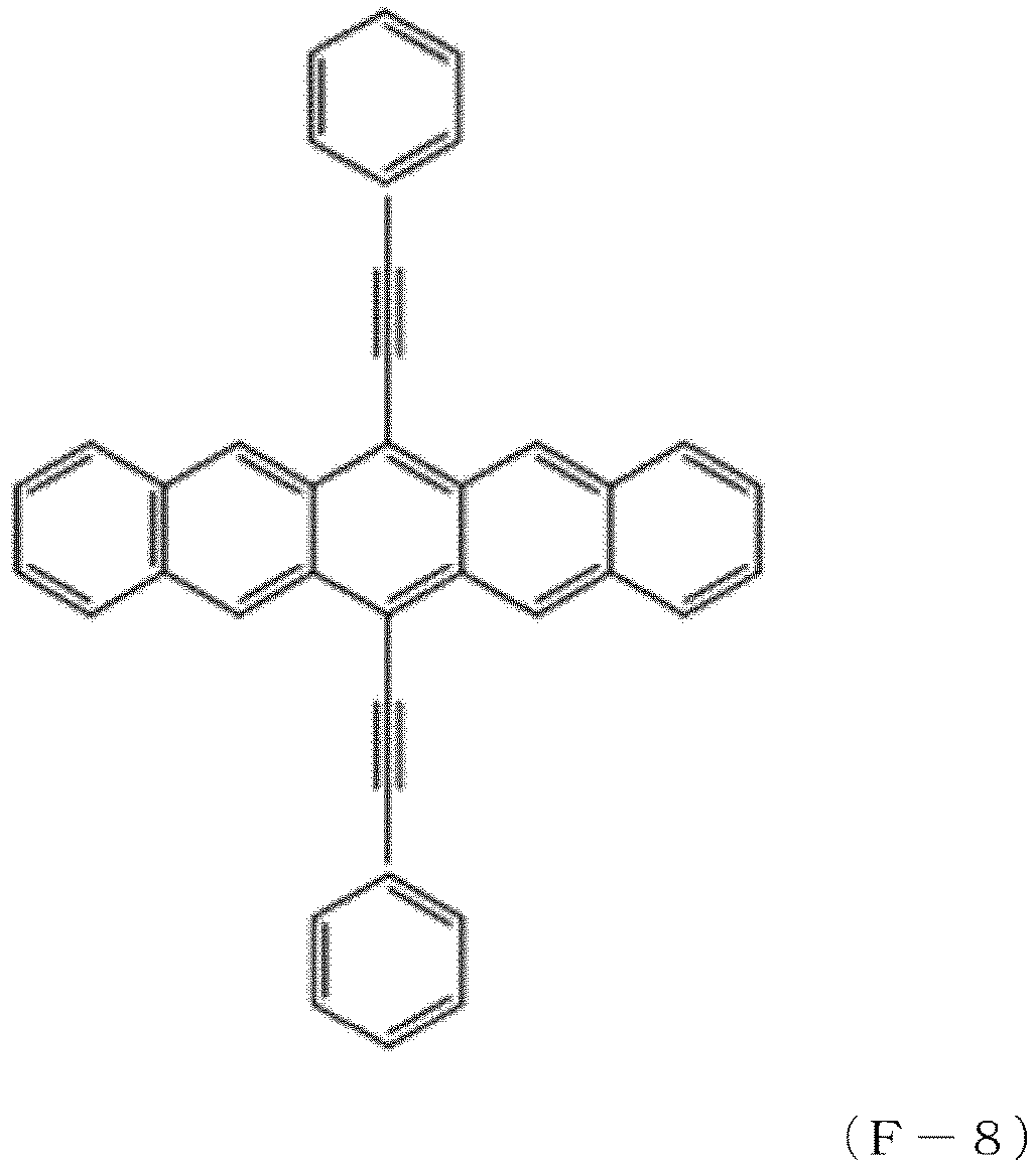


- Among the compounds of Formulae (F-1) to (F-10), the compounds of Formulae (F-2), (F-3), and (F-10) are preferred, and the compound of Formula (F-10) is particularly preferred.
- In the present disclosure, either of low-molecular-weight and high-molecular-weight organic semiconductors may be used. A mixture of these organic semiconductors may also be used.
- In the present disclosure, the organic semiconductor layer may be formed by any suitable method capable of forming a thin film layer of the organic semiconductor, such as a method of vapor-depositing the organic semiconductor under vacuum or a method of applying or printing a solution of the organic semiconductor in an organic solvent. The concentration of the organic semiconductor in the solution to be applied or printed is preferably 0.2 to 5% by weight for the formation of a more uniform semiconductor layer with a reduced thickness while it depends on the structure of the organic semiconductor and the solvent used. The organic solvent may be any type capable of dissolving the organic semiconductor at a certain concentration to enable film formation. Examples of the organic solvent include hexane, heptane, octane, decane, dodecane, tetradecane, decalin, indane, 1-methylnaphthalene, 2-ethylnaphthalene, 1,4-dimethylnaphthalene, a mixture of dimethylnaphthalene isomers, toluene, xylene, ethylbenzene, 1,2,4-trimethylbenzene, mesitylene, isopropylbenzene, pentylbenzene, hexylbenzene, tetralin, octylbenzene, cyclohexylbenzene, 1,2-dichlorobenzene, 1,3-dichlorobenzene, 1,4-dichlorobenzene, trichlorobenzene, 1,2-dimethoxybenzene, 1,3-dimethoxybenzene, γ-butyrolactone, 1,3-butylene glycol, ethylene glycol, benzyl alcohol, glycerin, cyclohexanol acetate, 3-methoxybutyl acetate, ethylene glycol monomethyl ether acetate, ethylene glycol monobutyl ether acetate, propylene glycol monomethyl ether acetate, anisole, cyclohexanone, mesitylene, 3-methoxybutyl acetate, cyclohexanol acetate, dipropylene glycol diacetate, dipropylene glycol methyl ether acetate, diethylene glycol monobutyl ether acetate, diethylene glycol monoethyl ether acetate, 1,6-hexanediol diacetate, 1,3-butylene glycol diacetate, 1,4-butanediol diacetate, ethyl acetate, phenyl acetate, dipropylene glycol dimethyl ether, dipropylene glycol methyl-N-propyl ether, tetradecahydrophenanthrene, 1,2,3,4,5,6,7,8-octahydrophenanthrene, decahydro-2-naphthol, 1,2,3,4-tetrahydro-1-naphthol, α-terpineol, isophorone triacetin decahydro-2-naphthol, dipropylene glycol dimethyl ether, 2,6-dimethylanisole, 1,2-dimethylanisole, 2,3-dimethylanisole, 3,4-dimethylanisole, 1-benzothiophene, 3-methylbenzothiophene, 1,2-dichloroethane, 1,1,2,2-tetrachloroethane, chloroform, dichloromethane, tetrahydrofuran, 1,2-dimethoxyethane, dioxane, cyclohexanone, acetone, methyl ethyl ketone, diethyl ketone, diisopropyl ketone, acetophenone, N,N-dimethylformamide, N-methyl-2-pyrrolidone, and limonene. For the production of a crystalline film with desired properties, an organic solvent having a high organic semiconductor-dissolving power and a boiling point of 100°C or more is appropriate, such as toluene, xylene, isopropylbenzene, anisole, cyclohexanone, mesitylene, 1,2-dichlorobenzene, 3,4-dimethylanisole, pentylbenzene, tetralin, cyclohexylbenzene, or decahydro-2-naphthol. A mixed solvent of two or more of these solvents in an appropriate proportion may also be used.
- If necessary, any of various organic or inorganic polymers or oligomers or organic or inorganic nanoparticles may be added in the form of a solid or an organic solvent dispersion to form the organic semiconductor layer. A polymer solution may also be applied onto the gate insulating layer to form a protective film. If necessary, various types of moisture-proof coating or light-resistant coating may also be performed on the protective film.
- Hereinafter, the present disclosure will be described in more detail with reference to examples, which are not intended to limit the present disclosure. The organic semiconductor (di-n-hexyldithienobenzodithiophene) used in the examples was synthesized according to the production method disclosed in
Japanese Unexamined Patent Application, Publication No. 2015-224238 - In the examples, NMR, spin coating, film thickness measurement, ultraviolet (UV) irradiation, vacuum deposition, and evaluation of the transfer characteristics and bias stress resistance of OFET devices were performed using the conditions and systems shown below.
- The 1H-NMR spectrum measurement was performed using JNM-ECZ400S FT-NMR (manufactured by JEOL Ltd.).
- The spin coater used was MS-A100 manufactured by Mikasa Co., Ltd.
- The film thickness was measured using Dektak XT Stylus Profiler manufactured by Bruker Corporation.
- The UV irradiation was performed under conditions at a UV dose of 14.2 mW/cm2 using UV Mask Aligner UPE-1605MA manufactured by Ushio Lighting, Inc.
- The vacuum deposition was performed using a compact vacuum deposition system VTR-350M/ERH manufactured by ULVAC Kikou Inc.
- A bottom-gate bottom-contact (BGBC) type organic field-effect transistor device was prepared and measured for transfer characteristics (Id-Vg) before bias voltage application. To evaluate the mobility, the measurement was performed through gate voltage (Vg) scanning using Semiconductor Parameter Analyzer 4200-SCS (manufactured by Keithley Instruments) with a source-drain voltage (Vd) of -15V in the BGBC type FET device. Subsequently, a gate voltage (Vg) of -30 V was continuously applied as a bias voltage for 1 hour to the device, and then the measurement was performed under the same conditions. From the resulting transfer characteristics, the absolute value of the change in threshold voltage before and after the bias voltage application was calculated for evaluation.
-
Resins 1 to 9 were synthesized as shown below. During the synthesis, the reaction, the purification, and the drying were all performed under yellow light or in the dark. The reason to conduct the synthesis under yellow light or in the dark was to prevent the photocyclization reaction of the photocyclizable compound and to prevent the photocyclization reaction of the resin resulting from the introduction of the photocyclizable compound. - In a 200 mL Schlenk tube, 8.3 g (38.4 mmol) of 3-(trifluoromethyl)cinnamic acid (manufactured by Tokyo Chemical Industry Co., Ltd.) were weighed. After a reflux tube was attached to the Schlenk tube, the air in the tube was replaced with nitrogen. To the Schlenk tube, a catalytic amount of DMF (manufactured by Fujifilm Wako Pure Chemicals), 33 mL of dichloromethane (manufactured by Fujifilm Wako Pure Chemicals), and 8.3 mL (115 mmol) of thionyl chloride (manufactured by Fujifilm Wako Pure Chemicals) were added in order using a syringe. The mixture was then stirred under reflux at 50°C for 4 hours using a water bath. After the heating was stopped, the reaction mixture was allowed to cool to room temperature. The solvent was then completely removed from the mixture by drying under reduced pressure for 1 hour, so that 3-(trifluoromethyl)cinnamic acid chloride was obtained.
- After the synthesis, 2.0 g of polystyrene with a weight average molecular weight of 55,000 (manufactured by DIC Corporation), 27 mL of dichloromethane, and 27 mL of ZEORORA H (manufactured by Zeon Corporation) were added to the Schlenk tube and dissolved with stirring at room temperature. After the solution was sufficiently cooled by placing the Schlenk tube in an ice bath for at least 30 minutes, 8.7 g (38.4 mmol) of trifluoromethanesulfonic acid (manufactured by Fujifilm Wako Pure Chemicals) was added dropwise to the solution using a syringe with stirring. As the dropwise addition proceeded, the color of the polymer solution turned to red purple. After the dropwise addition was completed, the mixture was stirred in ice bath for 1 hour and then allowed to react at room temperature for 5 hours. The solution resulting from the reaction was fed through a cannula to a saturated sodium hydrogen carbonate aqueous solution for neutralization of trifluoromethanesulfonic acid and hydrochloric acid in the system. The aqueous layer of the neutralized solution was removed by decantation, and the dichloromethane layer was separated. The process of adding water to the dichloromethane layer and removing the aqueous layer by decantation was performed twice to remove the excess of sodium hydrogen carbonate. After the decantation, the process of subjecting the solution to reprecipitation with 430 mL of methanol and isolating the resulting polymer by filtration was performed twice, and the product was then dried at 50°C under reduced pressure to give 4.9 g (85% yield) of
resin 1. - As a result of 1H-NMR analysis, the resulting resin 1 (of the formula below) was confirmed to include 21 mol% of the repeating unit represented by Formula (1) and 79 mol% of the repeating unit represented by Formula (2).


- The 1H-NMR chart of
resin 1 is shown inFIG. 2 .
1H-NMR (400 MHz, CDCl3): δ 7.60 (brs, -CH=CH-Ph), 7.45-6.46 (m, aromatic, -CH=CH-Ph), 2.05 (brs, -CH2-CH-), 1.73-1.42 (bm, - CH2-) - A 50 nm-thick gate electrode was formed by vacuum deposition of silver on a cleaned, dried glass (substrate) of 30 mm × 30 mm (Eagle XG manufactured by Corning Incorporated). A solution of resin 1 (11 wt%) in 2-methoxy-1-methylethyl acetate was applied onto the electrode-carrying substrate by spin coating under the conditions of 500 rpm for 5 seconds and 2,000 rpm for 20 seconds and then dried at 50°C for 1 minute (to form an insulating film). The resulting film was irradiated with 100 mJ/cm2 of ultraviolet rays to form a 500 nm-thick, crosslinked, gate insulating layer. Source and drain electrodes with a thickness of 50 nm, a channel length of 100 um, and a width of 500 um were formed by vacuum deposition of gold on the substrate having the gate electrode and the gate insulating layer. Immediately after the deposition, the substrate was immersed in an isopropanol solution of 30 mmol of pentafluorobenzenethiol, removed after 5 minutes from the solution, washed with isopropanol, and dried by blowing air. An organic semiconductor layer was then formed on the substrate by a drop casting process including: dropping 220 µL of a toluene solution of 0.8 wt% of an organic semiconductor (di-n-hexyldithienobenzodithiophene) on the substrate; allowing the drop on the substrate to stand for 15 hours in a dark thermostatic chamber; and heating the drop on the substrate at 40°C for 3 hours to volatilize the solvent. A bottom-gate bottom-contact (BGBC) type organic field-effect transistor device was manufactured by the above method.
- Table 1 shows the HOMO level of the repeating unit represented by Formula (2) in the synthesized resin, the mobility of the resulting organic field-effect transistor device, and the result of evaluation of its bias stress resistance.
[Table 1] Resin HOMO level of repeating unit of Formula (2) Transfer characteristics Bias stress resistance Mobility Change in threshold voltage before and after bias stress [eV] [cm2/V·s] [|V|] Example 1 -6.62 0.23 1.0 2 -6.58 0.20 1.4 3 -6.65 0.32 0.2 4 -6.85 0.32 0.2 5 -6.76 0.24 0.4 6 -6.83 0.35 1.6 7 -6.43 0.21 1.8 Comparative Example 8 -6.27 0.10 5.5 9 -6.09 0.05 4.0 - At a source-drain voltage (Vd) of -15 V, gate voltage (Vg) scanning was performed to measure the transfer characteristics (Id-Vg) of the field-effect transistor device before bias voltage application. As a result, the field-effect transistor device showed a high mobility of 0.23 cm2/V·s. Subsequently, a gate voltage (Vg) of -30 V was continuously applied for 1 hour to the field-effect transistor device, and then the measurement was performed under the same conditions. From the resulting transfer characteristics, the change in threshold voltage before and after the bias voltage application was calculated for evaluation. As a result, the change in threshold voltage was 1.0 V, which indicated high bias stress resistance.
FIG. 3 shows the transfer characteristics before and after the bias stress application. -
Resin 2 was obtained in an amount of 4.3 g (89% yield) in the same manner as in Example 1 except that 3-(trifluoromethyl)cinnamic acid was replaced with 2-(trifluoromethyl)cinnamic acid (manufactured by Tokyo Chemical Industry Co., Ltd.). - As a result of 1H-NMR analysis, the resulting resin 2 (of the formula below) was confirmed to include 26 mol% of the repeating unit represented by Formula (1) and 74 mol% of the repeating unit represented by Formula (2).

- An insulating film and an organic field-effect transistor device were formed in the same manner as in Example 1 except that the resulting
resin 2 was used instead and the UV irradiation dose was changed to 500 mJ/cm2. The transfer characteristics were evaluated in the same manner as in the case ofresin 1. As a result, the organic field-effect transistor device showed a mobility of 0.20 cm2/V·s, and the change in threshold voltage before and after the bias stress application was 1.4 V, which indicated high mobility and high bias stress resistance. The evaluation results are also shown in Table 1. -
Resin 3 was obtained in an amount of 3.8 g (72% yield) in the same manner as in Example 1 except that 3-(trifluoromethyl)cinnamic acid was replaced with 4-(trifluoromethyl)cinnamic acid (Tokyo Chemical Industry Co., Ltd.). - As a result of 1H-NMR analysis, the resulting resin 3 (of the formula below) was confirmed to include 14 mol% of the repeating unit represented by Formula (1) and 86 mol% of the repeating unit represented by Formula (2).

- An insulating film and an organic field-effect transistor were formed in the same manner as in Example 1 except that the resulting
resin 3 was used instead. The transfer characteristics were evaluated in the same manner as in the case ofresin 1. As a result, the organic field-effect transistor device showed a mobility of 0.32 cm2/V·s, and the change in threshold voltage before and after the bias stress application was 0.2 V, which indicated high mobility and high bias stress resistance. The evaluation results are also shown in Table 1. -
Resin 4 was obtained in an amount of 4.0 g (80% yield) in the same manner as in Example 1 except that 3-(trifluoromethyl)cinnamic acid was replaced with trans-3,5-bis(trifluoromethyl)cinnamic acid (manufactured by Apollo Scientific) and that the amount of trifluoromethanesulfonic acid was changed to 7.2 g (48 mmol). - As a result of 1H-NMR analysis, the resulting resin 4 (of the formula below) was confirmed to include 22 mol% of the repeating unit represented by Formula (1) and 78 mol% of the repeating unit represented by Formula (2).


- An insulating film and an organic field-effect transistor device were formed in the same manner as in Example 1 except that the resulting
resin 4 was used instead and the solution concentration was changed to 12 wt%. The transfer characteristics were evaluated in the same manner as in the case ofresin 1. As a result, the organic field-effect transistor device showed a mobility of 0.32 cm2/V·s, and the change in threshold voltage before and after the bias stress application was 0.2 V, which indicated high mobility and high bias stress resistance. The evaluation results are also shown in Table 1. -
Resin 5 was obtained in an amount of 3.0 g (53% yield) in the same manner as in Example 1 except that 3-(trifluoromethyl)cinnamic acid was replaced with 2,3,4,5,6-pentafluorocinnamic acid (manufactured by Tokyo Chemical Industry Co., Ltd.). - As a result of 1H-NMR analysis, the resulting resin 5 (of the formula below) was confirmed to include 13 mol% of the repeating unit represented by Formula (1) and 87 mol% of the repeating unit represented by Formula (2).

- An insulating film and an organic field-effect transistor device were formed in the same manner as in Example 1 except that the resulting
resin 5 was used instead and the UV irradiation dose was changed to 200 mJ/cm2. The transfer characteristics were evaluated in the same manner as in the case ofresin 1. As a result, the organic field-effect transistor device showed a mobility of 0.24 cm2/V·s, and the change in threshold voltage was 0.4 V, which indicated high mobility and high bias stress resistance. The evaluation results are also shown in Table 1. -
Resin 6 was obtained in an amount of 4.0 g (80% yield) in the same manner as in Example 1 except that 3-(trifluoromethyl)cinnamic acid was replaced with 3-nitrocinnamic acid (manufactured by Tokyo Chemical Industry Co., Ltd.). - As a result of 1H-NMR analysis, the resulting resin 6 (of the formula below) was confirmed to include 57 mol% of the repeating unit represented by Formula (1) and 43 mol% of the repeating unit represented by Formula (2).

- An insulating film and an organic field-effect transistor device were formed in the same manner as in Example 1 except that the resulting
resin 6 was used instead. The transfer characteristics were evaluated in the same manner as in the case ofresin 1. As a result, the organic field-effect transistor device showed a mobility of 0.35 cm2/V·s, and the change in threshold voltage was 1.6 V, which indicated high mobility and high bias stress resistance. The evaluation results are also shown in Table 1. -
Resin 7 was obtained in an amount of 3.7 g (82% yield) in the same manner as in Example 1 except that 3-(trifluoromethyl)cinnamic acid was replaced with 3-fluorocinnamic acid (manufactured by Tokyo Chemical Industry Co., Ltd.). - As a result of 1H-NMR analysis, the resulting resin 7 (of the formula below) was confirmed to include 23 mol% of the repeating unit represented by Formula (1) and 77 mol% of the repeating unit represented by Formula (2).

- An insulating film and an organic field-effect transistor device were formed in the same manner as in Example 1 except that the resulting
resin 7 was used instead. The transfer characteristics were evaluated in the same manner as in the case ofresin 1. As a result, the organic field-effect transistor device showed a mobility of 0.21 cm2/V·s, and the change in threshold voltage was 1.8 V, which indicated high mobility and high bias stress resistance. The evaluation results are also shown in Table 1. - In a glove box, 6.4 g (38.4 mmol) of cinnamic acid chloride (manufactured by Fujifilm Wako Pure Chemicals) and 2.0 g of polystyrene with a weight average molecular weight of 55,000 (manufactured by DIC Corporation) were weighed in a 200 mL Schlenk tube. After the Schlenk tube was taken out of the glove box, 29 mL of dichloromethane was added to the Schlenk tube, and the mixture was dissolved at room temperature with stirring. With stirring, 5.8 g (38.4 mmol) of trifluoromethanesulfonic acid (manufactured by Fujifilm Wako Pure Chemicals) was slowly added dropwise to the solution using a syringe. As the dropwise addition proceeded, the color of the polymer solution turned to red purple. After the dropwise addition was completed, the mixture was allowed to react at room temperature for 4 hours. The solution resulting from the reaction was fed through a cannula to a saturated sodium hydrogen carbonate aqueous solution for neutralization of trifluoromethanesulfonic acid and hydrochloric acid in the system. The aqueous layer of the neutralized solution was removed by decantation, and the dichloromethane layer was separated. The process of adding water to the dichloromethane layer and removing the aqueous layer by decantation was performed twice to remove the excess of sodium hydrogen carbonate. After the decantation, the process of subjecting the solution to reprecipitation with 430 mL of methanol and isolating the resulting polymer by filtration was performed twice, and the product was then dried at 50°C under reduced pressure to give 3.7 g (91% yield) of
resin 8. - As a result of 1H-NMR analysis, the resulting resin 8 (of the formula below) was confirmed to include 17 mol% of the repeating unit represented by Formula (1) and 83 mol% of the repeating unit represented by Formula (2).
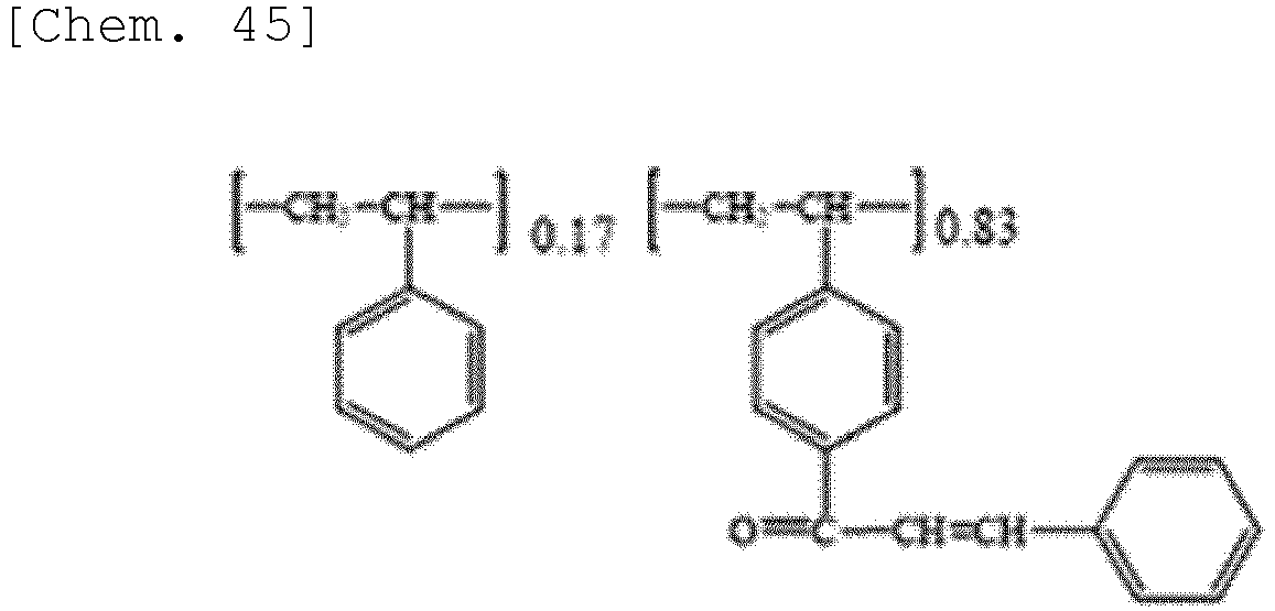
- An insulating film and an organic field-effect transistor device were formed in the same manner as in Example 1 except that the resulting
resin 8 was used instead. The transfer characteristics were evaluated in the same manner as in the case ofresin 1. As a result, the organic field-effect transistor device showed a mobility of 0.10 cm2/V·s, and the change in threshold voltage was 5.5 V, which indicated lower mobility and lower bias stress resistance than Examples 1 to 7. Table 1 shows the features of the prepared organic field-effect transistor device and the evaluation results. - Resin 9 was obtained in an amount of 4.0 g (70% yield) in the same manner as in Example 1 except that 3-(trifluoromethyl)cinnamic acid was replaced with 4-methylcinnamic acid (manufactured by Tokyo Chemical Industry Co., Ltd.).
- As a result of 1H-NMR analysis, the resulting resin 9 (of the formula below) was confirmed to include 6 mol% of the repeating unit represented by Formula (1) and 94 mol% of the repeating unit represented by Formula (2).

- An insulating film and an organic field-effect transistor device were formed in the same manner as in Example 1 except that the resulting resin 9 was used instead and the UV irradiation dose was changed to 1,000 mJ/cm2. The transfer characteristics were evaluated in the same manner as in the case of
resin 1. As a result, the organic field-effect transistor device showed a mobility of 0.05 cm2/V·s, and the change in threshold voltage was 4.0 V, which indicated lower mobility and lower bias stress resistance than Examples 1 to 7. Table 1 shows the features of the prepared organic field-effect transistor device and the evaluation results. - The organic field-effect transistor of each of Examples 1 to 7 prepared using the resin including the repeating unit of Formula (2) with a HOMO level of at most -6.4 eV exhibits higher mobility and higher bias stress resistance than that of Comparative Example 1 or 2 prepared using the resin including the repeating unit of Formula (2) with a HOMO level of more than -6.4 eV.
- There is provided a resin suitable for high-quality, organic field-effect transistor devices, which can be manufactured by printed electronics technology.
- While the present disclosure has been described in detail with reference to specific embodiments, it will be apparent to a person skilled in the art that the embodiments may be altered or modified in various ways without departing from the spirit and scope of the present disclosure. The present application is based on a Japanese patent application (
Japanese Patent Application No. 2021-175454) filed on October 27, 2021 -
- 1:
- Organic field-effect transistor device
- 11:
- Substrate (glass)
- 12:
- Source electrode
- 13:
- Drain electrode
- 14:
- Organic semiconductor layer
- 15:
- Gate electrode
- 16:
- Gate insulating layer
Claims (4)
- A resin comprising: a repeating unit represented by Formula (1); and a repeating unit represented by Formula (2), the repeating unit represented by Formula (2) having a HOMO level of -6.4 eV or less, the resin containing 20 mol% or more of the repeating unit represented by Formula (2) based on the total moles of the repeating unit represented by Formula (1) and the repeating unit represented by Formula (2),


- The resin according to claim 1, wherein the repeating unit represented by Formula (2) has at least one selected from the group consisting of a halogen atom, a cyano group, a nitro group, a carboxyalkyl group, and a fluoroalkyl group.
- An insulating film comprising a crosslinked product of the resin according to claim 1 or 2.
- In an organic field effect transistor device in which an organic semiconductor layer having a source electrode and a drain electrode and a gate electrode are laminated on a substrate with a gate insulating layer interposed therebetween, an organic field effect transistor device, characterized in that the gate insulating layer is the insulating film according to claim 3.
Applications Claiming Priority (2)
| Application Number | Priority Date | Filing Date | Title |
|---|---|---|---|
| JP2021175454A JP7803082B2 (en) | 2021-10-27 | 2021-10-27 | Photocrosslinkable polymer, insulating film and organic field effect transistor device including the same |
| PCT/JP2022/039467 WO2023074606A1 (en) | 2021-10-27 | 2022-10-24 | Resin, insulating film and organic field effect transistor comprising same |
Publications (3)
| Publication Number | Publication Date |
|---|---|
| EP4421851A1 true EP4421851A1 (en) | 2024-08-28 |
| EP4421851A4 EP4421851A4 (en) | 2025-04-16 |
| EP4421851B1 EP4421851B1 (en) | 2026-04-22 |
Family
ID=86159907
Family Applications (1)
| Application Number | Title | Priority Date | Filing Date |
|---|---|---|---|
| EP22886933.5A Active EP4421851B1 (en) | 2021-10-27 | 2022-10-24 | Resin, insulating film and organic field effect transistor comprising same |
Country Status (7)
| Country | Link |
|---|---|
| US (1) | US20240425620A1 (en) |
| EP (1) | EP4421851B1 (en) |
| JP (1) | JP7803082B2 (en) |
| KR (1) | KR20240093507A (en) |
| CN (1) | CN118160078A (en) |
| TW (1) | TW202334996A (en) |
| WO (1) | WO2023074606A1 (en) |
Family Cites Families (8)
| Publication number | Priority date | Publication date | Assignee | Title |
|---|---|---|---|---|
| US7981989B2 (en) * | 2006-11-28 | 2011-07-19 | Polyera Corporation | Photopolymer-based dielectric materials and methods of preparation and use thereof |
| JP6318863B2 (en) | 2014-05-29 | 2018-05-09 | 東ソー株式会社 | Method for producing dithienobenzodithiophene derivative |
| JP6821991B2 (en) * | 2016-07-27 | 2021-01-27 | 東ソー株式会社 | Insulating film and organic field effect transistor device containing it |
| US12291587B2 (en) * | 2017-03-16 | 2025-05-06 | Tosoh Corporation | Photocrosslinkable polymer, insulating film, planarization film, lyophilic/liquid repellent patterned film, and organic field effect transistor device comprising same |
| JP6992546B2 (en) | 2017-03-16 | 2022-02-03 | 東ソー株式会社 | Photocrosslinkable polymers, insulating films, flattening films, repellent patterning films and organic field effect transistor devices containing them |
| JP2019178191A (en) * | 2018-03-30 | 2019-10-17 | 東ソー株式会社 | Fluorine resin |
| JP7480484B2 (en) * | 2019-09-26 | 2024-05-10 | 東ソー株式会社 | Resin composition |
| JP2021175454A (en) | 2020-05-01 | 2021-11-04 | 富士フイルム株式会社 | Medical image processing equipment, methods and programs |
-
2021
- 2021-10-27 JP JP2021175454A patent/JP7803082B2/en active Active
-
2022
- 2022-10-24 US US18/704,567 patent/US20240425620A1/en active Pending
- 2022-10-24 EP EP22886933.5A patent/EP4421851B1/en active Active
- 2022-10-24 KR KR1020247013815A patent/KR20240093507A/en active Pending
- 2022-10-24 WO PCT/JP2022/039467 patent/WO2023074606A1/en not_active Ceased
- 2022-10-24 CN CN202280071572.1A patent/CN118160078A/en active Pending
- 2022-10-25 TW TW111140401A patent/TW202334996A/en unknown
Also Published As
| Publication number | Publication date |
|---|---|
| EP4421851A4 (en) | 2025-04-16 |
| EP4421851B1 (en) | 2026-04-22 |
| US20240425620A1 (en) | 2024-12-26 |
| TW202334996A (en) | 2023-09-01 |
| KR20240093507A (en) | 2024-06-24 |
| JP7803082B2 (en) | 2026-01-21 |
| WO2023074606A1 (en) | 2023-05-04 |
| JP2023064968A (en) | 2023-05-12 |
| CN118160078A (en) | 2024-06-07 |
Similar Documents
| Publication | Publication Date | Title |
|---|---|---|
| CN107266680B (en) | Transistor and method of manufacturing the same | |
| JP4612786B2 (en) | Manufacturing method of organic field effect transistor | |
| EP3019553B1 (en) | Azide-based crosslinking agents | |
| JP5913107B2 (en) | Organic semiconductor material, organic semiconductor composition, organic thin film, field effect transistor, and manufacturing method thereof | |
| EP2109162A1 (en) | Organic semiconductor composite, organic transistor material and organic field effect transistor | |
| JP6821991B2 (en) | Insulating film and organic field effect transistor device containing it | |
| EP2405505B1 (en) | Organic thin film transistor | |
| US20150123041A1 (en) | Semiconductor composition | |
| Fusco et al. | Novel DPP derivatives functionalized with auxiliary electron-acceptor groups and characterized by narrow bandgap and ambipolar charge transport properties | |
| KR20130000323A (en) | Electronic device | |
| CN104221177A (en) | Photocurable polymeric material and related electronic device | |
| EP3597673B1 (en) | Photocrosslinkable polymer, insulating film, planarization film, lyophilic/liquid repellent patterned film, and organic field effect transistor device comprising same | |
| JP2015199716A (en) | Polycyclic fused ring compounds, organic semiconductor materials, organic semiconductor devices, and organic transistors | |
| EP4421851B1 (en) | Resin, insulating film and organic field effect transistor comprising same | |
| US20100121004A1 (en) | Purification process for semiconducting monomers | |
| CN100585902C (en) | Organic Semiconductor Materials and Organic Field Effect Transistors | |
| TWI573194B (en) | Insulation film for semiconductor and organic film transister using the same | |
| CN1891754B (en) | Novel organic polymer semiconductor, method for forming organic polymer semiconductor thin film and organic thin film transistor using the same | |
| JP5363771B2 (en) | Nitrogen-containing condensed ring compound, nitrogen-containing condensed ring polymer, organic thin film and organic thin film element | |
| US20260013312A1 (en) | Photosensitive organic insulating material composition, insulating film, gate insulating film, transistor, electronic device, and method for manufacturing transistor | |
| JP6953986B2 (en) | Photocrosslinkable polymers, insulating films and organic field effect transistor devices containing them | |
| Liu et al. | Cyclopentadithiophene based branched polymer electrets synthesized by friedel–crafts polymerization | |
| JP2019167523A (en) | Polymerizable compound, photocurable polymer, insulation film, protection film, and organic transistor device |
Legal Events
| Date | Code | Title | Description |
|---|---|---|---|
| STAA | Information on the status of an ep patent application or granted ep patent |
Free format text: STATUS: THE INTERNATIONAL PUBLICATION HAS BEEN MADE |
|
| PUAI | Public reference made under article 153(3) epc to a published international application that has entered the european phase |
Free format text: ORIGINAL CODE: 0009012 |
|
| STAA | Information on the status of an ep patent application or granted ep patent |
Free format text: STATUS: REQUEST FOR EXAMINATION WAS MADE |
|
| 17P | Request for examination filed |
Effective date: 20240523 |
|
| AK | Designated contracting states |
Kind code of ref document: A1 Designated state(s): AL AT BE BG CH CY CZ DE DK EE ES FI FR GB GR HR HU IE IS IT LI LT LU LV MC ME MK MT NL NO PL PT RO RS SE SI SK SM TR |
|
| DAV | Request for validation of the european patent (deleted) | ||
| DAX | Request for extension of the european patent (deleted) | ||
| A4 | Supplementary search report drawn up and despatched |
Effective date: 20250319 |
|
| RIC1 | Information provided on ipc code assigned before grant |
Ipc: H10K 10/46 20230101ALI20250313BHEP Ipc: C08F 212/32 20060101ALI20250313BHEP Ipc: C08F 212/14 20060101ALI20250313BHEP Ipc: C08F 8/26 20060101ALI20250313BHEP Ipc: H01L 21/312 20060101AFI20250313BHEP |
|
| REG | Reference to a national code |
Ref country code: DE Ref legal event code: R079 Free format text: PREVIOUS MAIN CLASS: H01L0021312000 Ipc: H10K0085100000 Ref country code: DE Ref legal event code: R079 Ref document number: 602022035277 Country of ref document: DE Free format text: PREVIOUS MAIN CLASS: H01L0021312000 Ipc: H10K0085100000 |
|
| GRAP | Despatch of communication of intention to grant a patent |
Free format text: ORIGINAL CODE: EPIDOSNIGR1 |
|
| STAA | Information on the status of an ep patent application or granted ep patent |
Free format text: STATUS: GRANT OF PATENT IS INTENDED |
|
| RIC1 | Information provided on ipc code assigned before grant |
Ipc: H10K 85/10 20230101AFI20251128BHEP Ipc: H10K 10/46 20230101ALI20251128BHEP |
|
| INTG | Intention to grant announced |
Effective date: 20251218 |
|
| GRAS | Grant fee paid |
Free format text: ORIGINAL CODE: EPIDOSNIGR3 |
|
| GRAA | (expected) grant |
Free format text: ORIGINAL CODE: 0009210 |
|
| STAA | Information on the status of an ep patent application or granted ep patent |
Free format text: STATUS: THE PATENT HAS BEEN GRANTED |
|
| AK | Designated contracting states |
Kind code of ref document: B1 Designated state(s): AL AT BE BG CH CY CZ DE DK EE ES FI FR GB GR HR HU IE IS IT LI LT LU LV MC ME MK MT NL NO PL PT RO RS SE SI SK SM TR |
|
| REG | Reference to a national code |
Ref country code: CH Ref legal event code: F10 Free format text: ST27 STATUS EVENT CODE: U-0-0-F10-F00 (AS PROVIDED BY THE NATIONAL OFFICE) Effective date: 20260422 Ref country code: GB Ref legal event code: FG4D |
|
| REG | Reference to a national code |
Ref country code: DE Ref legal event code: R096 Ref document number: 602022035277 Country of ref document: DE |