EP4421837A1 - Exhaust grid for an arc extinguishing device - Google Patents
Exhaust grid for an arc extinguishing device Download PDFInfo
- Publication number
- EP4421837A1 EP4421837A1 EP23305250.5A EP23305250A EP4421837A1 EP 4421837 A1 EP4421837 A1 EP 4421837A1 EP 23305250 A EP23305250 A EP 23305250A EP 4421837 A1 EP4421837 A1 EP 4421837A1
- Authority
- EP
- European Patent Office
- Prior art keywords
- arc
- exhaust
- zone
- arc extinguishing
- extinguishing device
- Prior art date
- Legal status (The legal status is an assumption and is not a legal conclusion. Google has not performed a legal analysis and makes no representation as to the accuracy of the status listed.)
- Pending
Links
Images



Classifications
-
- H—ELECTRICITY
- H01—ELECTRIC ELEMENTS
- H01H—ELECTRIC SWITCHES; RELAYS; SELECTORS; EMERGENCY PROTECTIVE DEVICES
- H01H9/00—Details of switching devices, not covered by groups H01H1/00 - H01H7/00
- H01H9/30—Means for extinguishing or preventing arc between current-carrying parts
- H01H9/34—Stationary parts for restricting or subdividing the arc, e.g. barrier plate
- H01H9/346—Details concerning the arc formation chamber
-
- H—ELECTRICITY
- H01—ELECTRIC ELEMENTS
- H01H—ELECTRIC SWITCHES; RELAYS; SELECTORS; EMERGENCY PROTECTIVE DEVICES
- H01H9/00—Details of switching devices, not covered by groups H01H1/00 - H01H7/00
- H01H9/30—Means for extinguishing or preventing arc between current-carrying parts
- H01H9/34—Stationary parts for restricting or subdividing the arc, e.g. barrier plate
- H01H9/342—Venting arrangements for arc chutes
-
- H—ELECTRICITY
- H01—ELECTRIC ELEMENTS
- H01H—ELECTRIC SWITCHES; RELAYS; SELECTORS; EMERGENCY PROTECTIVE DEVICES
- H01H73/00—Protective overload circuit-breaking switches in which excess current opens the contacts by automatic release of mechanical energy stored by previous operation of a hand reset mechanism
- H01H73/02—Details
- H01H73/18—Means for extinguishing or suppressing arc
-
- H—ELECTRICITY
- H01—ELECTRIC ELEMENTS
- H01H—ELECTRIC SWITCHES; RELAYS; SELECTORS; EMERGENCY PROTECTIVE DEVICES
- H01H9/00—Details of switching devices, not covered by groups H01H1/00 - H01H7/00
- H01H9/30—Means for extinguishing or preventing arc between current-carrying parts
- H01H9/34—Stationary parts for restricting or subdividing the arc, e.g. barrier plate
- H01H2009/348—Provisions for recirculation of arcing gasses to improve the arc extinguishing, e.g. move the arc quicker into the arcing chamber
Definitions
- the present invention relates to the domain of miniature circuit breakers, and more particularly to an arc quenching device comprised in a miniature circuit breaker for the purpose of rapidly extinguishing any electric arc which may have been formed upon the occurrence of a circuit interruption.
- the present invention relates in particular to an insulating rear plate adapted to be fixed at the back of an arc chute.
- a circuit breaker is an electrical safety device designed to protect an electrical circuit connected to the circuit breaker from possible damages caused by an electrical default, for example an overcurrent, a short circuit, etc.
- the main function of a circuit breaker is to automatically interrupt the electrical circuit, i. e. to open the circuit, by moving apart two contacts when a default is detected.
- a miniature circuit breaker (or "MCB”) is an electromagnetic device that embodies a complete enclosure of a circuit breaker inside a molded insulating material.
- An electric arc may be generated inside a miniature circuit breaker when the two contacts are separated to interrupt (open) the circuit.
- Miniature circuit breakers use air alone to extinguish the arc.
- electric arcs generated when two contacts are separated to interrupt the circuit, are electric currents that go from one contact to the other through ionized air.
- Circuit breakers contain so-called arc chutes, a stack of mutually insulated parallel metal plates that divide and cool the arc, thus permitting the cooling and evacuation of the ionized air.
- arc chutes a stack of mutually insulated parallel metal plates that divide and cool the arc, thus permitting the cooling and evacuation of the ionized air.
- Ionized air is evacuated through the arc chute and may then exit the miniature circuit breaker through ventilation openings (or exhaust vents). It is however important to prevent any electric arc to reappear behind the arc chute as it may damage the circuit breaker.
- German patent DE 10 2009 056 190 filed in 2009 discloses an arc extinguishing device for an electrical switching device such as a miniature circuit breaker.
- an electrical switching device such as a miniature circuit breaker.
- a dividing wall divides the exhaust air flow of the arc-extinguishing gases emerging from the ventilation openings into a first and a second partial exhaust air flow, with the partial exhaust air flows running in opposite directions.
- FIG 1 is a representation of an arc extinguishing device according to the state of the art.
- Figure 1 shows an arc extinguishing device 1, for example for a miniature circuit-breaker, comprising an arc extinguishing chamber 2, the arc extinguishing chamber 2 comprising a plurality of arc splitter plates 4 stacked on top of each other, forming an arc splitter stack 3, and being kept apart from each other in the direction of stacking.
- the arc splitter stack 3 is arranged between an upper arc guide rail 19 and a lower arc guide rail 20, which run parallel to the plurality of arc splitter plates 4 and form the upper and lower limits of the arc splitter stack 3.
- each of the two contacts of the circuit breaker that can be separated to interrupt the circuit may be connected to either the upper arc guide rail 19 or the lower arc guide rail 20 respectively.
- an electric arc may be generated in the arc extinguishing chamber 2 and may enter the arc splitter stack 3 via the arc inlet side 23.
- Exhaust air produced by the burning electric arc is dissipated via the arc outlet side, opposite to the arc inlet side 23, that is to say, in figure 1 , in the right side of the arc extinguishing device 1.
- a rear plate 5 is fixed at the rear of the arc splitter stack 3, the rear plate comprising openings 6, 6' to let the exhaust air flows outside the arc splitter stack 3.
- This rear plate 5 comprises a partition wall 7 and redirect the outgoing exhaust air from openings 6 and 6' according to two opposite air flows 8 and 9.
- exhaust air outgoing through the rear plate 5 may still comprise ionized air and an electric arc may reform itself at the rear of the arc splitter stack 3, reducing the effectiveness of the arc extinguishing device 1 and possibly causing damages to the device comprising the arc extinguishing device 1 or, even worst, possibly initiating an electric arc with the outside of the arc extinguishing device 1 through the air exhausts, which can present a security risk.
- Another object of the present invention is to provide an improved arc extinguishing device for a miniature circuit breaker.
- an arc extinguishing device for a circuit-breaker comprising an arc splitter stack, the arc splitter stack comprising a plurality of extinguishing splitter plates stacked on top of each other and being kept apart from each other in the direction of stacking, the arc extinguishing device comprising an insulating rear plate fixed at the back of the arc splitter stack, the insulation rear plate being subdivided into a first and a second vertical portions, each vertical portion comprising respectively a first and a second exhaust zone, each exhaust zone comprising one or more vents facing spaces between two adjacent extinguishing splitter plates, the first exhaust zone being located in an upper part of the first portion, the second exhaust zone being located in a lower part of the second portion.
- the exhaust air outgoing from the arc extinguishing device is split in two parts, the top and the bottom parts of the exhaust air being separated so that an electric arc cannot short cut the arc extinguishing device by reforming itself behind the insulating rear plate.
- the first and second exhaust zone are separated by a vertical partition wall arranged to prevent exhaust air flow between the two exhaust zones.
- each vertical portion comprises respectively a first and a second insulation zone, the first insulation zone being located in a lower part of the first portion, below the first exhaust zone, the second insulation zone being located in an upper part of the second portion, above the second exhaust zone.
- the insulating rear plate comprises one or more positioning ribs adapted to be inserted between two adjacent extinguishing splitter plates.
- the width of the first exhaust zone and the width of the second exhaust zone are different.
- the invention also concerns a miniature circuit breaker comprising an arc extinguishing device as presently disclosed, the arc extinguishing device being placed in the miniature circuit breaker to extinguish an electric arc generated in an arc extinguishing chamber, the miniature circuit breaker being adapted to direct the exhaust air outgoing from the first exhaust zone to the arc extinguishing chamber.
- the miniature circuit breaker can redirect the air flow exiting from the first exhaust zone inside the miniature circuit breaker toward the arc extinguishing chamber to create a circulation of air and help the insertion of the electric arc inside the arc splitter stack.
- Another advantage is to limit the amount of ionized air that can escape from the miniature circuit breaker by directing part of the air flow to the internal recirculation without penalizing the arc insertion. This avoids possible external ignition caused by ionized air outside the miniature circuit breaker.
- the miniature circuit breaker is adapted to direct the exhaust air outgoing from the second exhaust zone to an exhaust vent of the miniature circuit breaker.
- FIG. 1 An exemplary embodiment of an arc extinguishing device 100 according to an exemplary embodiment of the present invention and of a miniature circuit breaker 500 comprising such arc extinguishing device 100 are shown in figures 2 to 5 .
- a same coordinate system with X, Y and Z axes is represented in the figures 2 to 5 .
- the axe Y represents the vertical direction in the said figures.
- Figure 2 is a representation of an arc extinguishing device 100 according to an exemplary embodiment of the present invention.
- the arc extinguishing device 100 mainly differs from the arc extinguishing device 1 previously described by an insulating rear plate 110.
- the arc extinguishing device 100 comprises a plurality of extinguishing splitter plates 104, forming an arc splitter stack 103.
- An extinguishing arc chamber 102 similar to the extinguishing arc chamber 2, is located in front of the arc extinguishing device 100.
- the insulating rear plate 110 is placed at the rear of the arc extinguishing device 100, more precisely the insulating rear plate 110 is fixed at the back of the arc splitter stack 103.
- the insulating rear plate 110 is possibly fixed to the arc splitter stack 103 via one or more positioning ribs as described hereafter.
- the insulating rear plate 110 is subdivided into a first vertical portion 120 and a second vertical portion 130.
- the vertical portion 120 comprises a first exhaust zone 120A.
- the vertical portion 130 comprises a second exhaust zone 130A.
- Each exhaust zone 120A and 130A comprises one or more vents 140 facing spaces between two adjacent extinguishing splitter plates 104. Exhaust air coming from the electric arc generated in the extinguishing arc chamber 102, going through the plurality of extinguishing splitter plates 104 may exit through the vents 140 of one or the other exhaust zone 120A and 130A.
- the first exhaust zone 120A is located in an upper part of the first portion 120.
- the second exhaust zone 130A is located in a lower part of the second portion 130.
- the two exhaust zones 120A and 130A may overlap in the middle of insulating rear plate 110.
- the first exhaust zone 120A, the upper one may go down more or less low in the first vertical portion 120.
- the second exhaust zone 130A, the lower one may go up more or less high in the second vertical portion 130.
- the two exhaust zones 120A and 130A may overlap in the lower and/or in the lower part of the insulating rear plate 110.
- the two exhaust zones 120A and 130A may not overlap.
- the first exhaust zone 120A and the second exhaust zone 130A are separated by a partition wall 150 arranged to prevent exhaust air flow between the two exhaust zones 120A and 130A. Therefore, no air flow may occur between the two exhaust zones 120A and 130A, preventing the creation of an electric arc at the rear of the arc splitter stack 103.
- each vertical portion 120 and 130 comprises respectively a first insulation zone 120B and a second insulation zone 130B.
- the first insulation zone 120B is located in a lower part of the first vertical portion 120, below the first exhaust zone 120A.
- the second insulation zone 130B is located in an upper part of the second vertical portion 130, above the second exhaust zone 130A.
- These insulation zones 120B and 130B are adapted to prevent any exhaust air flow.
- the insulation zones 120B and 130B may fill in entirely the space behind the arc extinguishing device 100 when the arc extinguishing device 110 is placed inside a device such as a miniature circuit breaker, leaving no room for any air flow.
- the insulation zones 120B and 130B may be placed against the wall behind the arc extinguishing device 100. This ensures that exhaust air is only circulated through the air exhaust zone 120A and 130A.
- exhaust zones 120A and 130A may comprise partition walls preventing any exhaust air flow from an exhaust zone to the other exhaust zone or to any insulation.
- FIG 3 is a representation of an insulating rear plate 110 according to the exemplary embodiment of the present invention.
- the insulating rear plate 110 is subdivided into a first vertical portion 120 and a second vertical portion 130.
- the vertical portion 120 comprises the first exhaust zone 120A.
- the vertical portion 130 comprises the second exhaust zone 130A.
- Each exhaust zone 120A and 130A comprises one or more vents 140 facing spaces between two adjacent extinguishing splitter plates 104.
- the two vertical portions 120 and 130 are here represented with a same width equal to half the width of the insulating rear plate 110.
- the width of the insulating rear plate 110 may be shared differently between the two vertical portions 120 and 130, one vertical portion could be larger than the other.
- the width of the first exhaust zone 120A and the width of the second exhaust zone 130A are possibly not equal. Said otherwise, the two widths are possibly different. Possibly, the sum of the width of the first exhaust zone 120A and the second exhaust zone 130A is lower than the width of the insulating rear plate 110, the remaining width being occupied for example by the partition wall 150.
- a vent or opening 140 is facing each space between two adjacent extinguishing splitter plates 104.
- a vent may be facing only some of the spaces between two adjacent extinguishing splitter plates 104, for example one out of two. This is another possibility to configure the respective area of the two exhaust zones 120A and 130A allowing air flow, and therefore configure the proportion of exhaust air going through each exhaust zone.
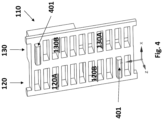
- FIG 4 is another representation of an insulating rear plate 110 according to the exemplary embodiment of the present invention.
- the insulating rear plate 110 is shown from behind, that is to say that the displayed portion is normally placed against the rear of the insulating rear plate 104.
- the insulating rear plate 110 may comprise one or more (here two) positioning ribs 401 adapted to be inserted between two adjacent extinguishing splitter plates 104 to position and fix the insulating rear plate 110 to the back of arc extinguishing device 100.
- Figure 5 is a representation of a miniature circuit breaker 500 comprising an arc extinguishing device 100 according to an exemplary embodiment of the present invention.
- the extinguishing arc chamber 102 is located in front of the arc extinguishing device 100.
- the insulating rear plate 110 is placed at the rear of the arc extinguishing device 100.
- the flow of ionized air created by the electric arc following the opening of the contacts is directed toward the arc extinguishing device 100 as illustrated by the arrows 501.
- This flow of ionized air 501 comes out of the arc extinguishing device 100 by the air exhaust zone 120A and the air exhaust zone 130A, creating two flows of air.
- Arrows 502 represent the air flow coming out from the air exhaust zone 120A, that is to say the upper exhaust zone of the insulating rear plate 110.
- Arrows 503 represent the air flow coming out from the air exhaust zone 130A, that is to say the lower exhaust zone of the insulating rear plate 110.
- Air flow coming out from the air exhaust zone 130A (arrows 503) is evacuated outside the miniature circuit breaker 500 through exhaust holes in the miniature circuit breaker 500.
- Air flow coming out from the air exhaust zone 120A (arrows 502) recirculates inside the miniature circuit breaker 500 as illustrated in the figure 5 and comes back to the extinguishing arc chamber 102, creating a flow of air self-maintained, and improving the air flow 501, that is to say the evacuation of the ionized air from the extinguishing arc chamber 102.
- the exact circuit of the air flow illustrated by the arrows 503 depends of the internal architecture of the miniature circuit breaker 500.
Landscapes
- Breakers (AREA)
- Arc-Extinguishing Devices That Are Switches (AREA)
Abstract
The invention concerns an arc extinguishing device for a circuit-breaker, comprising an arc splitter stack, the arc splitter stack comprising a plurality of extinguishing splitter plates stacked on top of each other and being kept apart from each other in the direction of stacking, the arc extinguishing device comprising an insulating rear plate being fixed at the back of the arc splitter stack, the insulation rear plate being subdivided into a first and a second vertical portions, each vertical portion comprising respectively a first and a second exhaust zone, each exhaust zone comprising one or more vents facing spaces between two adjacent extinguishing splitter plates, the first exhaust zone being located in an upper part of the first portion, the second exhaust zone being located in a lower part of the second portion.
Description
- The present invention relates to the domain of miniature circuit breakers, and more particularly to an arc quenching device comprised in a miniature circuit breaker for the purpose of rapidly extinguishing any electric arc which may have been formed upon the occurrence of a circuit interruption.
- The present invention relates in particular to an insulating rear plate adapted to be fixed at the back of an arc chute.
- A circuit breaker is an electrical safety device designed to protect an electrical circuit connected to the circuit breaker from possible damages caused by an electrical default, for example an overcurrent, a short circuit, etc. The main function of a circuit breaker is to automatically interrupt the electrical circuit, i. e. to open the circuit, by moving apart two contacts when a default is detected.
- A miniature circuit breaker (or "MCB") is an electromagnetic device that embodies a complete enclosure of a circuit breaker inside a molded insulating material.
- An electric arc (hereafter "arc") may be generated inside a miniature circuit breaker when the two contacts are separated to interrupt (open) the circuit. Miniature circuit breakers use air alone to extinguish the arc. In this case, electric arcs, generated when two contacts are separated to interrupt the circuit, are electric currents that go from one contact to the other through ionized air. Circuit breakers contain so-called arc chutes, a stack of mutually insulated parallel metal plates that divide and cool the arc, thus permitting the cooling and evacuation of the ionized air. By splitting the arc into smaller arcs, the arc is cooled down while the arc voltage is increased and serves as an additional impedance that limits the current through the circuit breaker. Such arc extinguishing device have been well known for years, as illustrated for example in
US patent 2,643,314 filed in the 1950 s. - Ionized air is evacuated through the arc chute and may then exit the miniature circuit breaker through ventilation openings (or exhaust vents). It is however important to prevent any electric arc to reappear behind the arc chute as it may damage the circuit breaker.
- German patent
DE 10 2009 056 190 filed in 2009 discloses an arc extinguishing device for an electrical switching device such as a miniature circuit breaker. As explained in this document in paragraph [0007], "Die Lichtbogenlöschgase enthalten ionisierte Bestandteile, wodurch es bei bekannten Lichtbogenlöscheinrichtungen insbesondere bei hohen Kurzschlussströmen im Ableitbereich der Lichtbogenlöschgase zu Überschlägen sowie zu gegenseitiger Beeinflussung kommen kann", or, translated in English, "the arc extinguishing gases contain ionised components, which can lead to flashovers and mutual interference in known arc extinguishing devices, especially with high short-circuit currents in the discharge area of the arc extinguishing gases". - According to the disclosure of German patent
DE 10 2009 056 190 , in order to prevent such problems, a dividing wall divides the exhaust air flow of the arc-extinguishing gases emerging from the ventilation openings into a first and a second partial exhaust air flow, with the partial exhaust air flows running in opposite directions. - This is illustrated in
figure 1 of the documentDE 10 2009 056 190 , which is reproduced (with some minor amendments) asfigure 1 in present document.Figure 1 is a representation of an arc extinguishing device according to the state of the art. -
Figure 1 shows an arcextinguishing device 1, for example for a miniature circuit-breaker, comprising anarc extinguishing chamber 2, the arcextinguishing chamber 2 comprising a plurality of arc splitter plates 4 stacked on top of each other, forming anarc splitter stack 3, and being kept apart from each other in the direction of stacking. Thearc splitter stack 3 is arranged between an upperarc guide rail 19 and a lowerarc guide rail 20, which run parallel to the plurality of arc splitter plates 4 and form the upper and lower limits of thearc splitter stack 3. When the arcextinguishing device 1 is installed in a device such a miniature circuit breaker, each of the two contacts of the circuit breaker that can be separated to interrupt the circuit may be connected to either the upperarc guide rail 19 or the lowerarc guide rail 20 respectively. When the two contacts are separated to open the circuit, an electric arc may be generated in the arcextinguishing chamber 2 and may enter thearc splitter stack 3 via thearc inlet side 23. Exhaust air produced by the burning electric arc is dissipated via the arc outlet side, opposite to thearc inlet side 23, that is to say, infigure 1 , in the right side of the arcextinguishing device 1. According to the disclosure ofDE 10 2009 056 190 , a rear plate 5 is fixed at the rear of thearc splitter stack 3, the rearplate comprising openings 6, 6' to let the exhaust air flows outside thearc splitter stack 3. This rear plate 5 comprises a partition wall 7 and redirect the outgoing exhaust air fromopenings 6 and 6' according to twoopposite air flows 8 and 9. - According to the cause of the formation of the electric arc, exhaust air outgoing through the rear plate 5 may still comprise ionized air and an electric arc may reform itself at the rear of the
arc splitter stack 3, reducing the effectiveness of the arc extinguishingdevice 1 and possibly causing damages to the device comprising the arc extinguishingdevice 1 or, even worst, possibly initiating an electric arc with the outside of the arc extinguishingdevice 1 through the air exhausts, which can present a security risk. - It is therefore an object of the present invention to improve the effectiveness and the security of the extinguishing of an electric arc by an arc extinguishing device, particularly by preventing the reappearance of an electric arc at the output of the arc extinguishing device.
- Another object of the present invention is to provide an improved arc extinguishing device for a miniature circuit breaker.
- The aforementioned objects are, at least partly, achieved by an arc extinguishing device for a circuit-breaker, comprising an arc splitter stack, the arc splitter stack comprising a plurality of extinguishing splitter plates stacked on top of each other and being kept apart from each other in the direction of stacking, the arc extinguishing device comprising an insulating rear plate fixed at the back of the arc splitter stack, the insulation rear plate being subdivided into a first and a second vertical portions, each vertical portion comprising respectively a first and a second exhaust zone, each exhaust zone comprising one or more vents facing spaces between two adjacent extinguishing splitter plates, the first exhaust zone being located in an upper part of the first portion, the second exhaust zone being located in a lower part of the second portion.
- Advantageously, the exhaust air outgoing from the arc extinguishing device is split in two parts, the top and the bottom parts of the exhaust air being separated so that an electric arc cannot short cut the arc extinguishing device by reforming itself behind the insulating rear plate.
- According to one embodiment, the first and second exhaust zone are separated by a vertical partition wall arranged to prevent exhaust air flow between the two exhaust zones.
- According to one embodiment, each vertical portion comprises respectively a first and a second insulation zone, the first insulation zone being located in a lower part of the first portion, below the first exhaust zone, the second insulation zone being located in an upper part of the second portion, above the second exhaust zone.
- According to one embodiment, the insulating rear plate comprises one or more positioning ribs adapted to be inserted between two adjacent extinguishing splitter plates.
- According to one embodiment, the width of the first exhaust zone and the width of the second exhaust zone are different.
- The invention also concerns a miniature circuit breaker comprising an arc extinguishing device as presently disclosed, the arc extinguishing device being placed in the miniature circuit breaker to extinguish an electric arc generated in an arc extinguishing chamber, the miniature circuit breaker being adapted to direct the exhaust air outgoing from the first exhaust zone to the arc extinguishing chamber.
- Advantageously, the miniature circuit breaker can redirect the air flow exiting from the first exhaust zone inside the miniature circuit breaker toward the arc extinguishing chamber to create a circulation of air and help the insertion of the electric arc inside the arc splitter stack. Another advantage is to limit the amount of ionized air that can escape from the miniature circuit breaker by directing part of the air flow to the internal recirculation without penalizing the arc insertion. This avoids possible external ignition caused by ionized air outside the miniature circuit breaker.
- According to one embodiment, the miniature circuit breaker is adapted to direct the exhaust air outgoing from the second exhaust zone to an exhaust vent of the miniature circuit breaker.
- Other characteristics and advantages shall appear in the following description of embodiments of the arc extinguishing device according to the invention, given by way of non-limiting examples, in reference to the annexed drawings wherein:
-
Figure 1 is a representation of an arc extinguishing device known from prior art; -
Figure 2 is a representation of an arc extinguishing device according to an exemplary embodiment of the present invention; -
Figure 3 is a representation of an insulating rear plate according to the exemplary embodiment of the present invention; -
Figure 4 is another representation of an insulating rear plate according to the exemplary embodiment of the present invention; -
Figure 5 is a representation of a miniature circuit breaker comprising an arc extinguishing device according to an exemplary embodiment of the present invention. - An exemplary embodiment of an arc
extinguishing device 100 according to an exemplary embodiment of the present invention and of aminiature circuit breaker 500 comprising such arcextinguishing device 100 are shown infigures 2 to 5 . - A same coordinate system with X, Y and Z axes is represented in the
figures 2 to 5 . The axe Y represents the vertical direction in the said figures. -
Figure 1 has been previously described. -
Figure 2 is a representation of an arcextinguishing device 100 according to an exemplary embodiment of the present invention. - The arc extinguishing
device 100 mainly differs from the arc extinguishingdevice 1 previously described by an insulatingrear plate 110. The arcextinguishing device 100 comprises a plurality of extinguishingsplitter plates 104, forming anarc splitter stack 103. Anextinguishing arc chamber 102, similar to theextinguishing arc chamber 2, is located in front of the arcextinguishing device 100. The insulatingrear plate 110 is placed at the rear of the arc extinguishingdevice 100, more precisely the insulatingrear plate 110 is fixed at the back of thearc splitter stack 103. The insulatingrear plate 110 is possibly fixed to thearc splitter stack 103 via one or more positioning ribs as described hereafter. - The insulating
rear plate 110 is subdivided into a firstvertical portion 120 and a secondvertical portion 130. Thevertical portion 120 comprises afirst exhaust zone 120A. Thevertical portion 130 comprises asecond exhaust zone 130A. Eachexhaust zone more vents 140 facing spaces between two adjacentextinguishing splitter plates 104. Exhaust air coming from the electric arc generated in theextinguishing arc chamber 102, going through the plurality of extinguishingsplitter plates 104 may exit through thevents 140 of one or theother exhaust zone - The
first exhaust zone 120A is located in an upper part of thefirst portion 120. Thesecond exhaust zone 130A is located in a lower part of thesecond portion 130. As shown infigure 2 , the twoexhaust zones rear plate 110. According to another embodiment, thefirst exhaust zone 120A, the upper one, may go down more or less low in the firstvertical portion 120. Similarly, thesecond exhaust zone 130A, the lower one, may go up more or less high in the secondvertical portion 130. According to another embodiment, the twoexhaust zones rear plate 110. According to another embodiment, the twoexhaust zones - According to one embodiment, the
first exhaust zone 120A and thesecond exhaust zone 130A are separated by apartition wall 150 arranged to prevent exhaust air flow between the twoexhaust zones exhaust zones arc splitter stack 103. - According to one embodiment, each
vertical portion first insulation zone 120B and asecond insulation zone 130B. Thefirst insulation zone 120B is located in a lower part of the firstvertical portion 120, below thefirst exhaust zone 120A. Thesecond insulation zone 130B is located in an upper part of the secondvertical portion 130, above thesecond exhaust zone 130A. Theseinsulation zones figure 2 , theinsulation zones arc extinguishing device 100 when thearc extinguishing device 110 is placed inside a device such as a miniature circuit breaker, leaving no room for any air flow. In this case, theinsulation zones arc extinguishing device 100. This ensures that exhaust air is only circulated through theair exhaust zone exhaust zones -
Figure 3 is a representation of an insulatingrear plate 110 according to the exemplary embodiment of the present invention. As infigure 2 , the insulatingrear plate 110 is subdivided into a firstvertical portion 120 and a secondvertical portion 130. Thevertical portion 120 comprises thefirst exhaust zone 120A. Thevertical portion 130 comprises thesecond exhaust zone 130A. Eachexhaust zone more vents 140 facing spaces between two adjacentextinguishing splitter plates 104. - The two
vertical portions rear plate 110. - According to another embodiment, the width of the insulating
rear plate 110 may be shared differently between the twovertical portions first exhaust zone 120A and the width of thesecond exhaust zone 130A are possibly not equal. Said otherwise, the two widths are possibly different. Possibly, the sum of the width of thefirst exhaust zone 120A and thesecond exhaust zone 130A is lower than the width of the insulatingrear plate 110, the remaining width being occupied for example by thepartition wall 150. This permits to configure the respective area of the twoexhaust zones exhaust zones exhaust zones - As shown in
figure 3 - andfigure 2 -, a vent oropening 140 is facing each space between two adjacentextinguishing splitter plates 104. According to another embodiment, a vent may be facing only some of the spaces between two adjacentextinguishing splitter plates 104, for example one out of two. This is another possibility to configure the respective area of the twoexhaust zones -
Figure 4 is another representation of an insulatingrear plate 110 according to the exemplary embodiment of the present invention. The insulatingrear plate 110 is shown from behind, that is to say that the displayed portion is normally placed against the rear of the insulatingrear plate 104. As shown, the insulatingrear plate 110 may comprise one or more (here two)positioning ribs 401 adapted to be inserted between two adjacentextinguishing splitter plates 104 to position and fix the insulatingrear plate 110 to the back ofarc extinguishing device 100. -
Figure 5 is a representation of aminiature circuit breaker 500 comprising anarc extinguishing device 100 according to an exemplary embodiment of the present invention. - As illustrated, the extinguishing
arc chamber 102 is located in front of thearc extinguishing device 100. The insulatingrear plate 110 is placed at the rear of thearc extinguishing device 100. The flow of ionized air created by the electric arc following the opening of the contacts is directed toward thearc extinguishing device 100 as illustrated by thearrows 501. This flow ofionized air 501 comes out of thearc extinguishing device 100 by theair exhaust zone 120A and theair exhaust zone 130A, creating two flows of air.Arrows 502 represent the air flow coming out from theair exhaust zone 120A, that is to say the upper exhaust zone of the insulatingrear plate 110.Arrows 503 represent the air flow coming out from theair exhaust zone 130A, that is to say the lower exhaust zone of the insulatingrear plate 110. - Air flow coming out from the
air exhaust zone 130A (arrows 503) is evacuated outside theminiature circuit breaker 500 through exhaust holes in theminiature circuit breaker 500. - Air flow coming out from the
air exhaust zone 120A (arrows 502) recirculates inside theminiature circuit breaker 500 as illustrated in thefigure 5 and comes back to the extinguishingarc chamber 102, creating a flow of air self-maintained, and improving theair flow 501, that is to say the evacuation of the ionized air from the extinguishingarc chamber 102. The exact circuit of the air flow illustrated by thearrows 503 depends of the internal architecture of theminiature circuit breaker 500. - As only a part of the ionized air is evacuated outside the
miniature circuit breaker 500 through theair flow 503, it avoids, or at least highly reduces, possible external ignition caused by ionized air outside theminiature circuit breaker 500.
Claims (7)
- Arc extinguishing device (100) for a circuit-breaker, comprising an arc splitter stack (103), the arc splitter stack comprising a plurality of extinguishing splitter plates (104) stacked on top of each other and being kept apart from each other in the direction of stacking, characterized in that:- an insulating rear plate (110) is fixed at the back of the arc splitter stack, the insulation rear plate being subdivided into a first and a second vertical portions (120, 130), each vertical portion comprising respectively a first and a second exhaust zone (120A, 130A), each exhaust zone comprising one or more vents (140) facing spaces between two adjacent extinguishing splitter plates,- the first exhaust zone being located in an upper part of the first portion,- the second exhaust zone being located in a lower part of the second portion.
- Arc extinguishing device according to claim 1, the first and second exhaust zone (120A, 130A) being separated by a vertical partition wall (150) arranged to prevent exhaust air flow between the two exhaust zones.
- Arc extinguishing device according to claim 1 or 2, each vertical portion comprising respectively a first and a second insulation zone (120B, 130B):- the first insulation zone (120B) being located in a lower part of the first portion, below the first exhaust zone (120A),- the second insulation zone (130B) being located in an upper part of the second portion, above the second exhaust zone (130A).
- Arc extinguishing device according to claim 1, 2 or 3, the insulating rear plate (110) comprising one or more positioning ribs (401) adapted to be inserted between two adjacent extinguishing splitter plates (104).
- Arc extinguishing device according to any preceding claim, the width of the first exhaust zone (120A) and the width of the second exhaust zone (130A) being different.
- A miniature circuit breaker (500) comprising an arc extinguishing device (100) according to any preceding claim, the arc extinguishing device being placed in the miniature circuit breaker to extinguish an electric arc generated in an arc extinguishing chamber, the miniature circuit breaker being adapted to:- direct the exhaust air outgoing from the first exhaust zone to the arc extinguishing chamber.
- A miniature circuit breaker according to previous claim, the miniature circuit breaker being adapted to:- direct the exhaust air outgoing from the second exhaust zone to an exhaust vent of the miniature circuit breaker.
Priority Applications (4)
| Application Number | Priority Date | Filing Date | Title |
|---|---|---|---|
| EP23305250.5A EP4421837A1 (en) | 2023-02-24 | 2023-02-24 | Exhaust grid for an arc extinguishing device |
| US18/442,388 US20240290558A1 (en) | 2023-02-24 | 2024-02-15 | Exhaust grid for an arc extinguishing device |
| AU2024200998A AU2024200998A1 (en) | 2023-02-24 | 2024-02-15 | Exhaust grid for an arc extinguishing device |
| CN202410201818.3A CN118553570A (en) | 2023-02-24 | 2024-02-23 | Exhaust grille for arc extinguishing device |
Applications Claiming Priority (1)
| Application Number | Priority Date | Filing Date | Title |
|---|---|---|---|
| EP23305250.5A EP4421837A1 (en) | 2023-02-24 | 2023-02-24 | Exhaust grid for an arc extinguishing device |
Publications (1)
| Publication Number | Publication Date |
|---|---|
| EP4421837A1 true EP4421837A1 (en) | 2024-08-28 |
Family
ID=85571262
Family Applications (1)
| Application Number | Title | Priority Date | Filing Date |
|---|---|---|---|
| EP23305250.5A Pending EP4421837A1 (en) | 2023-02-24 | 2023-02-24 | Exhaust grid for an arc extinguishing device |
Country Status (4)
| Country | Link |
|---|---|
| US (1) | US20240290558A1 (en) |
| EP (1) | EP4421837A1 (en) |
| CN (1) | CN118553570A (en) |
| AU (1) | AU2024200998A1 (en) |
Families Citing this family (1)
| Publication number | Priority date | Publication date | Assignee | Title |
|---|---|---|---|---|
| CN119725046B (en) * | 2025-02-17 | 2025-11-18 | 河北宝凯电气股份有限公司 | Free subassembly and arc extinguishing system disappear |
Citations (6)
| Publication number | Priority date | Publication date | Assignee | Title |
|---|---|---|---|---|
| US2643314A (en) | 1950-05-20 | 1953-06-23 | Ite Circuit Breaker Ltd | Arc chute |
| JPS6210831A (en) * | 1985-07-05 | 1987-01-19 | 三菱電機株式会社 | Arc extinguisher |
| EP1498921A1 (en) * | 2003-07-14 | 2005-01-19 | Eaton Corporation | Gas segregator barrier for electrical switching apparatus |
| DE102009056190B3 (en) | 2009-11-27 | 2011-05-12 | Abb Ag | Arc quenching device and switching device |
| EP4064307A1 (en) * | 2021-03-26 | 2022-09-28 | Schneider Electric Industries SAS | Electrical switching device |
| EP4113559A1 (en) * | 2021-06-29 | 2023-01-04 | Schneider Electric Industries SAS | Miniature circuit breaker |
Family Cites Families (5)
| Publication number | Priority date | Publication date | Assignee | Title |
|---|---|---|---|---|
| US2293452A (en) * | 1939-10-11 | 1942-08-18 | Gen Electric | Electric air circuit breaker |
| US2468422A (en) * | 1945-06-20 | 1949-04-26 | Ite Circuit Breaker Ltd | Arc chute |
| US2947839A (en) * | 1957-02-28 | 1960-08-02 | Allis Chalmers Mfg Co | Arc chute having cooling and deionizing elements arranged at the exhaust end |
| US3327080A (en) * | 1964-12-23 | 1967-06-20 | Allis Chalmers Mfg Co | Arc chute for electric circuit breaker |
| US10381180B1 (en) * | 2018-08-14 | 2019-08-13 | Siemens Industry, Inc. | Electric arc extinguishing apparatus for a molded case circuit breaker |
-
2023
- 2023-02-24 EP EP23305250.5A patent/EP4421837A1/en active Pending
-
2024
- 2024-02-15 US US18/442,388 patent/US20240290558A1/en active Pending
- 2024-02-15 AU AU2024200998A patent/AU2024200998A1/en active Pending
- 2024-02-23 CN CN202410201818.3A patent/CN118553570A/en active Pending
Patent Citations (6)
| Publication number | Priority date | Publication date | Assignee | Title |
|---|---|---|---|---|
| US2643314A (en) | 1950-05-20 | 1953-06-23 | Ite Circuit Breaker Ltd | Arc chute |
| JPS6210831A (en) * | 1985-07-05 | 1987-01-19 | 三菱電機株式会社 | Arc extinguisher |
| EP1498921A1 (en) * | 2003-07-14 | 2005-01-19 | Eaton Corporation | Gas segregator barrier for electrical switching apparatus |
| DE102009056190B3 (en) | 2009-11-27 | 2011-05-12 | Abb Ag | Arc quenching device and switching device |
| EP4064307A1 (en) * | 2021-03-26 | 2022-09-28 | Schneider Electric Industries SAS | Electrical switching device |
| EP4113559A1 (en) * | 2021-06-29 | 2023-01-04 | Schneider Electric Industries SAS | Miniature circuit breaker |
Non-Patent Citations (1)
| Title |
|---|
| DEGUI CHEN ET AL: "Effect of Different Vent Configurations on the Interruption Performance of Arc Chamber", IEICE TRANSACTIONS ON ELECTRONICS, INSTITUTE OF ELECTRONICS, TOKYO, JP, vol. E93C, no. 9, 1 September 2010 (2010-09-01), pages 1399 - 1403, XP001558298, ISSN: 0916-8524, DOI: 10.1587/TRANSELE.E93.C.1399 * |
Also Published As
| Publication number | Publication date |
|---|---|
| CN118553570A (en) | 2024-08-27 |
| AU2024200998A1 (en) | 2024-09-12 |
| US20240290558A1 (en) | 2024-08-29 |
Similar Documents
| Publication | Publication Date | Title |
|---|---|---|
| EP2064718B1 (en) | Gassing insulator, and arc chute assembly and electrical switching apparatus employing the same | |
| US7598833B1 (en) | Electrical switching apparatus, and arc chute assembly and arc hood assembly therefor | |
| EP2064717B1 (en) | Arc buffle, and arc chute assembly and electrical switching apparatus employing the same | |
| US8101881B2 (en) | Arc resistant switchgear vertical exhaust system | |
| US8247727B2 (en) | Arc chamber employing a number of gassing inserts to form a number of gas flow circulation paths and electrical switching apparatus including the same | |
| US20150270075A1 (en) | Modular gas exhaust assembly for a circuit breaker | |
| JPWO2008136113A1 (en) | Metal closed switchgear | |
| US7586057B2 (en) | Electrical switching apparatus and vented case therefor | |
| KR20180048150A (en) | Extinguishing Unit of Molded Case Circuit Breaker | |
| US9460870B2 (en) | Extinguishing chamber for an electric protection apparatus and electric protection apparatus comprising one such chamber | |
| CN101517681A (en) | Arc plate, and arc chute assembly and electrical switching apparatus employing the same | |
| US20240290558A1 (en) | Exhaust grid for an arc extinguishing device | |
| US11637415B2 (en) | Arc ventilation system of distributing board | |
| US6844514B2 (en) | Arc extinguisher with an attachment for low voltage switchgear | |
| KR102788607B1 (en) | Air circuit breaker having insulation paper to prevent terminal short circuit | |
| US20130112657A1 (en) | Arc chamber assembly for use in moulded case circuit breakers | |
| AU2022204661B2 (en) | Miniature circuit breaker | |
| US7545247B2 (en) | Electrical switching apparatus, and case and terminal shield therefor | |
| CN103117197B (en) | For the arc-chutes device of electromagentic switching apparatus | |
| KR20210133637A (en) | Grid to remove arc and assembly having the same | |
| KR102648597B1 (en) | Arc Ventilation System of Distrbuting Board | |
| KR100832329B1 (en) | Arc runner of the breaker |
Legal Events
| Date | Code | Title | Description |
|---|---|---|---|
| PUAI | Public reference made under article 153(3) epc to a published international application that has entered the european phase |
Free format text: ORIGINAL CODE: 0009012 |
|
| STAA | Information on the status of an ep patent application or granted ep patent |
Free format text: STATUS: THE APPLICATION HAS BEEN PUBLISHED |
|
| AK | Designated contracting states |
Kind code of ref document: A1 Designated state(s): AL AT BE BG CH CY CZ DE DK EE ES FI FR GB GR HR HU IE IS IT LI LT LU LV MC ME MK MT NL NO PL PT RO RS SE SI SK SM TR |
|
| STAA | Information on the status of an ep patent application or granted ep patent |
Free format text: STATUS: REQUEST FOR EXAMINATION WAS MADE |
|
| 17P | Request for examination filed |
Effective date: 20250228 |