EP4421606A1 - Method for implementing touch interaction, and touch interaction device - Google Patents
Method for implementing touch interaction, and touch interaction device Download PDFInfo
- Publication number
- EP4421606A1 EP4421606A1 EP23218870.6A EP23218870A EP4421606A1 EP 4421606 A1 EP4421606 A1 EP 4421606A1 EP 23218870 A EP23218870 A EP 23218870A EP 4421606 A1 EP4421606 A1 EP 4421606A1
- Authority
- EP
- European Patent Office
- Prior art keywords
- view
- application
- coordinates
- touch
- event
- Prior art date
- Legal status (The legal status is an assumption and is not a legal conclusion. Google has not performed a legal analysis and makes no representation as to the accuracy of the status listed.)
- Withdrawn
Links
Images

Classifications
-
- G—PHYSICS
- G06—COMPUTING OR CALCULATING; COUNTING
- G06F—ELECTRIC DIGITAL DATA PROCESSING
- G06F3/00—Input arrangements for transferring data to be processed into a form capable of being handled by the computer; Output arrangements for transferring data from processing unit to output unit, e.g. interface arrangements
- G06F3/01—Input arrangements or combined input and output arrangements for interaction between user and computer
- G06F3/048—Interaction techniques based on graphical user interfaces [GUI]
- G06F3/0487—Interaction techniques based on graphical user interfaces [GUI] using specific features provided by the input device, e.g. functions controlled by the rotation of a mouse with dual sensing arrangements, or of the nature of the input device, e.g. tap gestures based on pressure sensed by a digitiser
- G06F3/0488—Interaction techniques based on graphical user interfaces [GUI] using specific features provided by the input device, e.g. functions controlled by the rotation of a mouse with dual sensing arrangements, or of the nature of the input device, e.g. tap gestures based on pressure sensed by a digitiser using a touch-screen or digitiser, e.g. input of commands through traced gestures
- G06F3/04883—Interaction techniques based on graphical user interfaces [GUI] using specific features provided by the input device, e.g. functions controlled by the rotation of a mouse with dual sensing arrangements, or of the nature of the input device, e.g. tap gestures based on pressure sensed by a digitiser using a touch-screen or digitiser, e.g. input of commands through traced gestures for inputting data by handwriting, e.g. gesture or text
-
- G—PHYSICS
- G06—COMPUTING OR CALCULATING; COUNTING
- G06F—ELECTRIC DIGITAL DATA PROCESSING
- G06F3/00—Input arrangements for transferring data to be processed into a form capable of being handled by the computer; Output arrangements for transferring data from processing unit to output unit, e.g. interface arrangements
- G06F3/01—Input arrangements or combined input and output arrangements for interaction between user and computer
- G06F3/048—Interaction techniques based on graphical user interfaces [GUI]
- G06F3/0484—Interaction techniques based on graphical user interfaces [GUI] for the control of specific functions or operations, e.g. selecting or manipulating an object, an image or a displayed text element, setting a parameter value or selecting a range
-
- G—PHYSICS
- G06—COMPUTING OR CALCULATING; COUNTING
- G06F—ELECTRIC DIGITAL DATA PROCESSING
- G06F9/00—Arrangements for program control, e.g. control units
- G06F9/06—Arrangements for program control, e.g. control units using stored programs, i.e. using an internal store of processing equipment to receive or retain programs
- G06F9/44—Arrangements for executing specific programs
- G06F9/451—Execution arrangements for user interfaces
Definitions
- the disclosure relates to computer interaction technologies, and specifically to a method for implementing touch interaction, and a touch interaction device for implementing this method.
- a multi-application-view embedding solution is usually required, such as to embed an Android view into a Unity view.
- an embedded view is only for the purpose of display, but is not able to respond to events based on other views (e.g., touch actions), making it not possible to provide complete functions of a desktop framework.
- An objective of the disclosure is to provide a method for implementing touch interaction, and a touch interaction device for implementing this method, which can provide complete functions, including display and interaction, within a multi-application-view embedded architecture.
- a method for implementing touch interaction which includes:
- the first view and the second view are respectively a Unity view and an Android view.
- the type of the touch event includes an action-down event, an action-move event, and an action-up event.
- the second view is embedded into the first view by: creating, within the first view, a view control for displaying the second view, where the creation includes setting a start position and plane dimensions of the view control within the first view.
- the first application determines the proportional coordinates by:
- the first application sends the type and the proportional coordinates to the second application by means of an interprocess communication mechanism.
- the second application generates the operation instruction by:
- a touch interaction device which includes:
- the first view and the second view are respectively a Unity view and an Android view.
- the type of the touch event includes an action-down event, an action-move event, and an action-up event.
- the second view is embedded into the first view by: creating, within the first view, a view control for displaying the second view, where the creation includes setting a start position and plane dimensions of the view control within the first view.
- the first application determines the proportional coordinates by:
- the first application sends the type and the proportional coordinates to the second application by means of an interprocess communication mechanism.
- the second application generates the operation instruction by:
- the above touch interaction device may be a vehicle central console screen or a smart home central console screen.
- the first application determines a type and proportional coordinates, in a second view framework, of a touch event in a first view framework, and then sends the type and the proportional coordinates to the second application, such that the second application can respond to the touch event according to the second view framework.
- the above method has high universality, and can be applied to various embedded view architectures.
- these embodiments can be implemented purely in software without modifying hardware configurations or structures.
- first and second are not used to indicate sequences of the units in terms of time, space, size, etc., and are only used to distinguish between the units.
- FIG. 1 is a schematic diagram of an architecture of an automotive electronic system, and shows an exemplary manner of dividing functional blocks.
- the automotive electronic system 10 includes an autonomous driving domain 110, an intelligent cockpit domain 120, a vehicle body domain 130, a power assembly domain 140, and a chassis domain 150.
- these functional domains communicate with each other via a bus (for example, Ethernet).
- a bus for example, Ethernet
- division into the above functional domains is merely exemplary, and other manners are also feasible.
- the vehicle body domain may be integrated with the intelligent cockpit domain.
- the autonomous driving domain 110 provides a capability of data processing and computing, including data processing operations on devices such as a millimeter wave radar, a camera, a laser radar, a GPS, an inertial navigator, and a capability of making judgments required for autonomous driving. Further, the autonomous driving domain provides security protection of underlying core data and network connection data when a vehicle is in an autonomous driving state.
- the intelligent cockpit domain 120 is configured to perform functions of an automotive cockpit electronic system, which may be, for example, an integrated system or a vehicle central console screen that integrates a function of instrument information and multimedia entertainment information display and a function of human-machine interaction.
- an automotive cockpit electronic system which may be, for example, an integrated system or a vehicle central console screen that integrates a function of instrument information and multimedia entertainment information display and a function of human-machine interaction.
- the vehicle body domain 130 is configured to perform overall control over functions of a vehicle body, and may be, for example, a conventional body control module (BCM); or on this basis, further integrate functions such as a passive entry passive start (PEPS) system, ripple anti-pinch, and an air conditioning control system.
- BCM body control module
- PEPS passive entry passive start
- ripple anti-pinch ripple anti-pinch
- air conditioning control system an air conditioning control system
- the power domain 140 is configured to implement optimization and control of an automotive power assembly.
- the chassis domain 150 is configured to perform vehicle driving control, and includes, for example, an electric power steering (EPS) system, an electronic stability control (ESC) system, an electric brake booster, an airbag control system, an air suspension, a vehicle speed sensor, etc.
- EPS electric power steering
- ESC electronic stability control
- electric brake booster electric brake booster
- airbag control system an air suspension
- vehicle speed sensor etc.
- FIG. 2 is a schematic block diagram of a vehicle central console screen.
- the vehicle central console screen 220 shown in FIG. 2 includes a control unit 221 and a touch display screen 222.
- the control unit 221 includes a memory 2211, one or more processors 2212 (e.g., microcontrollers), and a computer program 2213 stored in the memory 2211 and runnable on the processor 2212.
- processors 2212 e.g., microcontrollers
- Various functions of the automotive cockpit electronic system are implemented by running the computer program 2213 on the processor 2212.
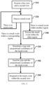
- FIG. 3 is a flowchart of a method for implementing touch interaction according to some embodiments of the disclosure.
- the vehicle central console screen shown in FIG. 2 is used as an exemplary apparatus to describe the steps of the method shown in FIG. 3 below.
- the embodiment shown in FIG. 3 is not limited to being applied to the vehicle central console screen shown in FIG. 2 , but it can also be applied to other types of touch interaction devices, such as a smart home central console screen.
- the computer program 2213 includes a first application 2213A and a second application 2213B.
- the first application 2213A and the second application 2213B can be run on the processor 2212 to implement the steps included in the method shown in FIG. 3 .
- the method shown in FIG. 3 includes the steps as follows.
- Step 310 Presentation of a first view and a second view
- the first application 2213A and the second application 2213B respectively present the first view V1 and the second view V2 on the touch display screen 222.
- the display of the first view V1 and the second view V2 on the touch display screen is implemented by the first application 2213A and the second application 2213B, respectively.
- the first view V1 and the second view V2 may be respectively a Unity view and an Android view.
- the second view V2 is an embedded view of the first view V1.
- the embedded view described herein may be understood that, from the perspective of a user, the second view V2 is considered as a part of the first view V1, and operations can be performed within a region VC of the first view V1 that corresponds to the second view V2 and within another region of the first view V1 in such a way that there is no difference to the user.
- the second view V2 can be embedded into the first view V1 by creating, within the first view V1, a view control VC for displaying the second view V2.
- the creation includes setting a start position and plane dimensions of the view control VC within the first view V1 (with a rectangular control as an example, the start position and the plane dimensions are respectively a position of one of vertexes of a rectangle, and a length and a width of the rectangle).
- the creation process can be completed by creating, within a Unity project of the first application, a Unity view control for displaying the Android view, and setting configuration parameters such as the start position and the plane dimensions.
- Step 320 Detection of a touch event
- step 320 the method procedure shown in FIG. 3 proceeds to step 320.
- the first application 2213A determines whether the touch event occurs within the region VC in the first view V1 that corresponds to the second view V2. If the touch event occurs within the corresponding region VC, the method procedure proceeds to step 330. If the touch event occurs within a region, other than the corresponding region VC, in the first view V1, the method procedure proceeds to step 340. If no touch event is detected, the detection continues.
- examples of a type of the touch event include, but are not limited to, an action-down event (where a pressure is applied to a surface of the touch display screen), an action-move event (where the position of the surface of the touch display screen to which the pressure is applied continues to change), and an action-up event (where the pressure applied to the surface of the touch display screen is released), etc.
- Step 330 Determination of the type and proportional coordinates of the touch event
- the first application 2213A determines, in response to the touch event occurring within the region VC in the first view V1 that corresponds to the second view V2, the type of the touch event and the proportional coordinates of the touch event within the second view.
- a correspondence or a mapping relationship between a type of a touch event within the first view V1 and a type of a touch event within the second view V2 can be established in advance, such that the first application 2213A can determine the corresponding type of the touch event within the second view V2 based on the type of the touch event that is detected in step 320.
- the first view V1 often has a different form and dimension from the second view V2.
- the first view may be a three-dimensional view, while the second view may be a two-dimensional view. Additionally, the first view occupies a larger region on the touch display screen than the second view. If the second application 2213B describes the position where the touch event occurs by using a coordinate system S1 corresponding to the first view V1, i.e., processes the touch event with coordinate values of the coordinate system S1 as parameter values, an incorrect response operation will be generally caused.
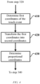
- FIG. 4 is a flowchart of a method for determining proportional coordinates according to some other embodiments of the disclosure, where the first view V1 and the second view V2 are still respectively used as the Unity view and the Android view in the method described. Referring to FIG. 4 , the method shown includes the following steps performed by the first application 2213A.
- the first application 2213A determines first coordinates or event coordinates of a touch event within a first coordinate system S1 corresponding to the first view V1. Since the first view is a three-dimensional view, the first coordinate system S1 is a spatial coordinate system, and correspondingly, the first coordinates can be denoted by P1 ( x 1 , y 1 , z 1 ) .
- the first coordinates P1 ( x 1 , y 1 , z 1 ) are transformed into second coordinates or local coordinates within a second coordinate system S2 corresponding to a view control VC.
- the second coordinate system S2 is a planar coordinate system, and correspondingly, the second coordinates can be denoted by P2 ( x 2 , y 2 ) .
- a ScreenPointToLocalPointInRectangle function of a RectTransformUtility class may be used to transform the first coordinates into the second coordinates.
- proportional coordinates P3 ( x 3 , y 3 ) are determined based on plane dimensions of the view control VC and the second coordinates P2 ( x 2 , y 2 ) .
- coordinate units of the second coordinate system may take any value (e.g., take one or more pixels on the touch display screen as coordinate units for horizontal and vertical axes).
- Step 340 Processing of a touch event within another region
- step 320 the first application 2213A processes the touch event based on execution logic for the first view V1, which will not be detailed here.
- Step 350 Transmission of the type and proportional coordinates of the touch event
- step 330 the method procedure shown in FIG. 3 proceeds to step 350.
- the first application 2213A sends, to the second application 2213B, the type (e.g., each event type defined in MotionEvent) and the proportional coordinates P3 ( x 3 , y 3 ) of the touch event that are determined in step 330.
- the type e.g., each event type defined in MotionEvent
- P3 proportional coordinates
- the first application 2213A may send the type and the proportional coordinates of the touch event to the second application 2213B by means of an interprocess communication mechanism.
- step 360 Response to the touch event within the second view
- step 330 the method procedure shown in FIG. 3 proceeds to step 350.
- the second application 2213B generates, based on the type and the proportional coordinates P3 ( x 3 , y 3 ) of the touch event that are sent by the first application 2213A, an operation instruction to respond to the touch event.
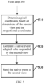
- FIG. 5 is a flowchart of a method for generating an operation instruction according to some other embodiments of the disclosure, where the first view V1 and the second view V2 are still respectively used as the Unity view and the Android view in the method described. Referring to FIG. 5 , the method shown includes the following steps performed by the second application 2213B.
- step 510 physical coordinates or pixel coordinates P4 ( x 4 , y 4 ) of a touch event on a touch display screen are determined based on plane dimensions of the second view V2 and proportional coordinates P3 ( x 3 , y 3 ) .
- step 520 after step 510 is performed, the method procedure shown in FIG. 5 proceeds to step 520.
- the second application 2213B generates, based on the type of the touch event that is sent by the first application 2213A and the pixel coordinates that are determined in step 510, a native event adapted to be responded to by the second view V2.
- the second application 2213B may encapsulate the type of the touch event and the pixel coordinates determined in step 510 into a MotionEvent Android native event.
- step 530 after step 520 is performed, the method procedure shown in FIG. 5 proceeds to step 530.
- the second application 2213B sends the native event to the second view V2, enabling an accurate response to be made to the touch event.
Landscapes
- Engineering & Computer Science (AREA)
- Theoretical Computer Science (AREA)
- General Engineering & Computer Science (AREA)
- Human Computer Interaction (AREA)
- Physics & Mathematics (AREA)
- General Physics & Mathematics (AREA)
- Software Systems (AREA)
- User Interface Of Digital Computer (AREA)
Abstract
The disclosure relates to computer interaction technologies, and specifically to a method for implementing touch interaction, and a touch interaction device for implementing this method. According to an aspect of the disclosure, the method for implementing touch interaction includes: presenting a first view and a second view on a touch display screen by a first application and a second application, respectively, where the second view is an embedded view of the first view; in response to a touch event occurring within a region in the first view that corresponds to the second view, determining, by the first application, the type of the touch event and proportional coordinates of the touch event within the second view; sending, by the first application, the type and the proportional coordinates to the second application; and generating, by the second application and based on the type and the proportional coordinates, an operation instruction to respond to the touch event.
Description
- The disclosure relates to computer interaction technologies, and specifically to a method for implementing touch interaction, and a touch interaction device for implementing this method.
- In a desktop framework architecture of a vehicle display system, a multi-application-view embedding solution is usually required, such as to embed an Android view into a Unity view. However, an embedded view is only for the purpose of display, but is not able to respond to events based on other views (e.g., touch actions), making it not possible to provide complete functions of a desktop framework.
- An objective of the disclosure is to provide a method for implementing touch interaction, and a touch interaction device for implementing this method, which can provide complete functions, including display and interaction, within a multi-application-view embedded architecture.
- According to an aspect of the disclosure, a method for implementing touch interaction is provided, which includes:
- presenting a first view and a second view on a touch display screen by a first application and a second application, respectively, where the second view is an embedded view of the first view;
- in response to a touch event occurring within a region in the first view that corresponds to the second view, determining, by the first application, the type of the touch event and proportional coordinates of the touch event within the second view;
- sending, by the first application, the type and the proportional coordinates to the second application; and
- generating, by the second application and based on the type and the proportional coordinates, an operation instruction to respond to the touch event.
- Optionally, in the above method, the first view and the second view are respectively a Unity view and an Android view.
- Further, in the above method, the type of the touch event includes an action-down event, an action-move event, and an action-up event.
- Further, in the above method, the second view is embedded into the first view by:
creating, within the first view, a view control for displaying the second view, where the creation includes setting a start position and plane dimensions of the view control within the first view. - Still further, in the above method, the first application determines the proportional coordinates by:
- determining first coordinates of the touch event within a first coordinate system corresponding to the first view;
- transforming the first coordinates into second coordinates within a second coordinate system corresponding to the view control; and
- determining the proportional coordinates based on the second coordinates and the plane dimensions of the view control.
- Optionally, in the above method, the first application sends the type and the proportional coordinates to the second application by means of an interprocess communication mechanism.
- Further, in the above method, the second application generates the operation instruction by:
- determining pixel coordinates of the touch event on the touch display screen based on the plane dimensions of the second view and the proportional coordinates;
- generating, based on the type and the pixel coordinates, a native event adapted to be responded to by the second view; and
- sending the native event to the second view.
- According to another aspect of the disclosure, a touch interaction device is provided, which includes:
- a touch display screen; and
- a control unit, including:
- a memory having a first application and a second application stored thereon; and
- at least one processor,
- where the first application and the second application are run on the at least one processor to:
- present a first view and a second view on the touch display screen by the first application and the second application, respectively, where the second view is an embedded view of the first view;
- in response to a touch event occurring within a region in the first view that corresponds to the second view, determine, by the first application, the type of the touch event and proportional coordinates of the touch event within the second view;
- send, by the first application, the type and the proportional coordinates to the second application; and
- generate, by the second application and based on the type and the proportional coordinates, an operation instruction to respond to the touch event.
- Optionally, in the above touch interaction device, the first view and the second view are respectively a Unity view and an Android view.
- Further, in the above touch interaction device, the type of the touch event includes an action-down event, an action-move event, and an action-up event.
- Further, in the above touch interaction device, the second view is embedded into the first view by:
creating, within the first view, a view control for displaying the second view, where the creation includes setting a start position and plane dimensions of the view control within the first view. - Further, in the above touch interaction device, the first application determines the proportional coordinates by:
- determining first coordinates of the touch event within a first coordinate system corresponding to the first view;
- transforming the first coordinates into second coordinates within a second coordinate system corresponding to the view control; and
- determining the proportional coordinates based on the second coordinates and the plane dimensions of the view control.
- Optionally, in the above touch interaction device, the first application sends the type and the proportional coordinates to the second application by means of an interprocess communication mechanism.
- Further, in the above touch interaction device, the second application generates the operation instruction by:
- determining pixel coordinates of the touch event on the touch display screen based on the plane dimensions of the second view and the proportional coordinates;
- generating, based on the type and the pixel coordinates, a native event adapted to be responded to by the second view; and
- sending the native event to the second view.
- In addition to the above one or more features, the above touch interaction device may be a vehicle central console screen or a smart home central console screen.
- In some embodiments of the disclosure, for the multi-application-view embedded architecture, the first application determines a type and proportional coordinates, in a second view framework, of a touch event in a first view framework, and then sends the type and the proportional coordinates to the second application, such that the second application can respond to the touch event according to the second view framework. The above method has high universality, and can be applied to various embedded view architectures. In addition, these embodiments can be implemented purely in software without modifying hardware configurations or structures.
- The above-mentioned and/or other aspects and advantages of the disclosure will become more apparent and more readily appreciated from the following description of various aspects in conjunction with the accompanying drawings, in which the same or similar units are denoted by the same reference numerals. In the accompanying drawings:
-
FIG. 1 is a schematic diagram of an architecture of an automotive electronic system; -
FIG. 2 is a schematic block diagram of a vehicle central console screen; -
FIG. 3 is a flowchart of a method for implementing touch interaction according to some embodiments of the disclosure; -
FIG. 4 is a flowchart of a method for determining proportional coordinates according to some other embodiments of the disclosure; and -
FIG. 5 is a flowchart of a method for generating an operation instruction according to some other embodiments of the disclosure. - The disclosure is described below more comprehensively with reference to the accompanying drawings in which schematic embodiments of the disclosure are shown. However, the disclosure may be implemented in different forms, and should not be construed as being limited to the embodiments provided herein. The embodiments provided above are intended to make the disclosure of this specification comprehensive and complete, to more comprehensively convey the scope of protection of the disclosure to those skilled in the art.
- In this specification, the terms such as "include" and "comprise" indicate that in addition to the units and steps that are directly and explicitly described in the specification and claims, other units and steps that are not directly or explicitly described are not excluded in the technical solutions of the disclosure.
- Unless otherwise specified, the terms such as "first" and "second" are not used to indicate sequences of the units in terms of time, space, size, etc., and are only used to distinguish between the units.
- An automotive electronic system may usually divide functional domains in various manners.
FIG. 1 is a schematic diagram of an architecture of an automotive electronic system, and shows an exemplary manner of dividing functional blocks. As shown inFIG. 1 , the automotiveelectronic system 10 includes an autonomous driving domain 110, anintelligent cockpit domain 120, avehicle body domain 130, apower assembly domain 140, and achassis domain 150. Exemplarily, these functional domains communicate with each other via a bus (for example, Ethernet). It should be noted that division into the above functional domains is merely exemplary, and other manners are also feasible. For example, the vehicle body domain may be integrated with the intelligent cockpit domain. - The autonomous driving domain 110 provides a capability of data processing and computing, including data processing operations on devices such as a millimeter wave radar, a camera, a laser radar, a GPS, an inertial navigator, and a capability of making judgments required for autonomous driving. Further, the autonomous driving domain provides security protection of underlying core data and network connection data when a vehicle is in an autonomous driving state.
- The
intelligent cockpit domain 120 is configured to perform functions of an automotive cockpit electronic system, which may be, for example, an integrated system or a vehicle central console screen that integrates a function of instrument information and multimedia entertainment information display and a function of human-machine interaction. - The
vehicle body domain 130 is configured to perform overall control over functions of a vehicle body, and may be, for example, a conventional body control module (BCM); or on this basis, further integrate functions such as a passive entry passive start (PEPS) system, ripple anti-pinch, and an air conditioning control system. - The
power domain 140 is configured to implement optimization and control of an automotive power assembly. Thechassis domain 150 is configured to perform vehicle driving control, and includes, for example, an electric power steering (EPS) system, an electronic stability control (ESC) system, an electric brake booster, an airbag control system, an air suspension, a vehicle speed sensor, etc. -
FIG. 2 is a schematic block diagram of a vehicle central console screen. The vehiclecentral console screen 220 shown inFIG. 2 includes acontrol unit 221 and atouch display screen 222. With continued reference toFIG. 2 , thecontrol unit 221 includes amemory 2211, one or more processors 2212 (e.g., microcontrollers), and acomputer program 2213 stored in thememory 2211 and runnable on theprocessor 2212. Various functions of the automotive cockpit electronic system are implemented by running thecomputer program 2213 on theprocessor 2212. -
FIG. 3 is a flowchart of a method for implementing touch interaction according to some embodiments of the disclosure. The vehicle central console screen shown inFIG. 2 is used as an exemplary apparatus to describe the steps of the method shown inFIG. 3 below. However, upon reading the content described below, it should be understood that the embodiment shown inFIG. 3 is not limited to being applied to the vehicle central console screen shown inFIG. 2 , but it can also be applied to other types of touch interaction devices, such as a smart home central console screen. - Exemplarily, the
computer program 2213 includes a first application 2213A and a second application 2213B. The first application 2213A and the second application 2213B can be run on theprocessor 2212 to implement the steps included in the method shown inFIG. 3 . Specifically, the method shown inFIG. 3 includes the steps as follows. - In
step 310, the first application 2213A and the second application 2213B respectively present the first view V1 and the second view V2 on thetouch display screen 222. In other words, the display of the first view V1 and the second view V2 on the touch display screen is implemented by the first application 2213A and the second application 2213B, respectively. In some embodiments, the first view V1 and the second view V2 may be respectively a Unity view and an Android view. - In addition, exemplarily, it is assumed that the second view V2 is an embedded view of the first view V1. The embedded view described herein may be understood that, from the perspective of a user, the second view V2 is considered as a part of the first view V1, and operations can be performed within a region VC of the first view V1 that corresponds to the second view V2 and within another region of the first view V1 in such a way that there is no difference to the user.
- In some embodiments, the second view V2 can be embedded into the first view V1 by creating, within the first view V1, a view control VC for displaying the second view V2. The creation includes setting a start position and plane dimensions of the view control VC within the first view V1 (with a rectangular control as an example, the start position and the plane dimensions are respectively a position of one of vertexes of a rectangle, and a length and a width of the rectangle). With the first view V1 and the second view V2 as the Unity view and the Android view, respectively, the creation process can be completed by creating, within a Unity project of the first application, a Unity view control for displaying the Android view, and setting configuration parameters such as the start position and the plane dimensions.
- After
step 310 is performed, the method procedure shown inFIG. 3 proceeds to step 320. In this step, the first application 2213A determines whether the touch event occurs within the region VC in the first view V1 that corresponds to the second view V2. If the touch event occurs within the corresponding region VC, the method procedure proceeds to step 330. If the touch event occurs within a region, other than the corresponding region VC, in the first view V1, the method procedure proceeds to step 340. If no touch event is detected, the detection continues. Exemplarily, examples of a type of the touch event include, but are not limited to, an action-down event (where a pressure is applied to a surface of the touch display screen), an action-move event (where the position of the surface of the touch display screen to which the pressure is applied continues to change), and an action-up event (where the pressure applied to the surface of the touch display screen is released), etc. - In
step 330, the first application 2213A determines, in response to the touch event occurring within the region VC in the first view V1 that corresponds to the second view V2, the type of the touch event and the proportional coordinates of the touch event within the second view. In some embodiments, a correspondence or a mapping relationship between a type of a touch event within the first view V1 and a type of a touch event within the second view V2 can be established in advance, such that the first application 2213A can determine the corresponding type of the touch event within the second view V2 based on the type of the touch event that is detected instep 320. With the first view V1 and the second view V2 as the Unity view and the Android view, respectively, there is a correspondence between the touch event in the Unity view and the touch event in the Android view, as shown in Table 1 below:Table 1 Unity view Android view Action-down event received by IPointerUpHandler interface ACTION_DOWN event in MotionEvent Touch action-up event received by IPointerUpHandler interface ACTION_DOWN event in MotionEvent Swipe event received by IMoveHandler interface ACTION_MOVE event in MotionEvent - The first view V1 often has a different form and dimension from the second view V2. For example, the first view may be a three-dimensional view, while the second view may be a two-dimensional view. Additionally, the first view occupies a larger region on the touch display screen than the second view. If the second application 2213B describes the position where the touch event occurs by using a coordinate system S1 corresponding to the first view V1, i.e., processes the touch event with coordinate values of the coordinate system S1 as parameter values, an incorrect response operation will be generally caused.
- In the disclosure, such errors are avoided by using the proportional coordinates.
FIG. 4 is a flowchart of a method for determining proportional coordinates according to some other embodiments of the disclosure, where the first view V1 and the second view V2 are still respectively used as the Unity view and the Android view in the method described. Referring toFIG. 4 , the method shown includes the following steps performed by the first application 2213A. - In
step 410, the first application 2213A determines first coordinates or event coordinates of a touch event within a first coordinate system S1 corresponding to the first view V1. Since the first view is a three-dimensional view, the first coordinate system S1 is a spatial coordinate system, and correspondingly, the first coordinates can be denoted by P1 (x 1, y 1, z 1) . - In
step 420, the first coordinates P1 (x 1, y 1, z 1) are transformed into second coordinates or local coordinates within a second coordinate system S2 corresponding to a view control VC. As the view control is a planar region, the second coordinate system S2 is a planar coordinate system, and correspondingly, the second coordinates can be denoted by P2 (x 2, y 2) . Exemplarily, a ScreenPointToLocalPointInRectangle function of a RectTransformUtility class may be used to transform the first coordinates into the second coordinates. - In
step 430, proportional coordinates P3 (x 3, y 3) are determined based on plane dimensions of the view control VC and the second coordinates P2 (x 2, y 2) .Exemplarily, assuming that a ratio of the length to width of the view control is a : b, the proportional coordinates P3 (x 3, y 3) may be determined according to the following formula:

- In the above formula, the symbol [ ] represents a rounding operation.
- It should be noted that coordinate units of the second coordinate system may take any value (e.g., take one or more pixels on the touch display screen as coordinate units for horizontal and vertical axes).
- In another sub-step of
step 320, the first application 2213A processes the touch event based on execution logic for the first view V1, which will not be detailed here. - After
step 330 is performed, the method procedure shown inFIG. 3 proceeds to step 350. In this step, the first application 2213A sends, to the second application 2213B, the type (e.g., each event type defined in MotionEvent) and the proportional coordinates P3 (x 3, y 3) of the touch event that are determined instep 330. - In some embodiments, the first application 2213A may send the type and the proportional coordinates of the touch event to the second application 2213B by means of an interprocess communication mechanism.
- After
step 330 is performed, the method procedure shown inFIG. 3 proceeds to step 350. In this step, the second application 2213B generates, based on the type and the proportional coordinates P3 (x 3, y 3) of the touch event that are sent by the first application 2213A, an operation instruction to respond to the touch event. -
FIG. 5 is a flowchart of a method for generating an operation instruction according to some other embodiments of the disclosure, where the first view V1 and the second view V2 are still respectively used as the Unity view and the Android view in the method described. Referring toFIG. 5 , the method shown includes the following steps performed by the second application 2213B. - In
step 510, physical coordinates or pixel coordinates P4 (x 4, y 4) of a touch event on a touch display screen are determined based on plane dimensions of the second view V2 and proportional coordinates P3 (x 3, y 3) . Exemplarily, assuming that the second view spans M and N pixels respectively in length and width directions, the pixel coordinates P4 (x 4, y 4) may be determined according to the following formula:

- In
step 520, afterstep 510 is performed, the method procedure shown inFIG. 5 proceeds to step 520. In this step, the second application 2213B generates, based on the type of the touch event that is sent by the first application 2213A and the pixel coordinates that are determined instep 510, a native event adapted to be responded to by the second view V2. Exemplarily, the second application 2213B may encapsulate the type of the touch event and the pixel coordinates determined instep 510 into a MotionEvent Android native event. - In
step 530, afterstep 520 is performed, the method procedure shown inFIG. 5 proceeds to step 530. In this step, the second application 2213B sends the native event to the second view V2, enabling an accurate response to be made to the touch event. Those skilled in the art can understand that various illustrative logical blocks, modules, circuits, and algorithm steps described in this specification may be implemented as electronic hardware, computer software, or a combination thereof. - To demonstrate interchangeability between the hardware and the software, various illustrative parts, blocks, modules, circuits, and steps above have been described comprehensively based on their functionalities. Whether to implement such functionalities in a form of hardware or software depends on specific application and design constrains imposed on an overall system. Those skilled in the art may implement the described functionalities for specific and particular application based on manners of change. However, determination of such an implementation should not be understood as a departure from the scope of the disclosure.
- Although only some specific embodiments of the disclosure are described, those of ordinary skill in the art should understand that the disclosure may be implemented in many other forms without departing from the essence and scope of the disclosure. Therefore, the presented examples and implementations are deemed as illustrative rather than restrictive, and without departing from the spirit and scope of the disclosure defined by the appended claims, the disclosure may cover various modifications and substitutions.
- The embodiments and examples proposed herein are provided to describe as adequately as possible embodiments according to the technology and specific applications thereof and thus enable those skilled in the art to implement and use the disclosure. However, those skilled in the art will know that the above descriptions and examples are provided only for description and illustration. The proposed description is not intended to cover all aspects of the disclosure or limit the disclosure to the disclosed precise forms.
Claims (15)
- A method for implementing touch interaction, the method comprising:presenting a first view and a second view on a touch display screen by a first application and a second application, respectively, wherein the second view is an embedded view of the first view;in response to a touch event occurring within a region in the first view that corresponds to the second view, determining, by the first application, the type of the touch event and proportional coordinates of the touch event within the second view;sending, by the first application, the type and the proportional coordinates to the second application; andgenerating, by the second application and based on the type and the proportional coordinates, an operation instruction to respond to the touch event.
- The method according to claim 1, wherein the first view and the second view are respectively a Unity view and an Android view.
- The method according to claim 1 or 2, wherein the type of the touch event comprises an action-down event, an action-move event, and an action-up event.
- The method according to any one of claims 1 to 3, wherein the second view is embedded into the first view by:
creating, within the first view, a view control for displaying the second view, wherein the creation comprises setting a start position and plane dimensions of the view control within the first view. - The method according to claim 4, wherein the first application determines the proportional relationship by:determining first coordinates of the touch event within a first coordinate system corresponding to the first view;transforming the first coordinates into second coordinates within a second coordinate system corresponding to the view control; anddetermining the proportional coordinates based on the second coordinates and the plane dimensions of the view control.
- The method according to any one of claims 1 to 5, wherein the first application sends the type and the proportional coordinates to the second application by means of an interprocess communication mechanism.
- The method according to claim 5, wherein the second application generates the operation instruction by:determining pixel coordinates of the touch event on the touch display screen based on the plane dimensions of the second view and the proportional coordinates;generating, based on the type and the pixel coordinates, a native event adapted to be responded to by the second view; andsending the native event to the second view.
- A touch interaction device, comprising:a touch display screen; anda control unit, comprising:a memory having a first application and a second application stored thereon; andat least one processor,wherein the first application and the second application are run on the at least one processor to:present a first view and a second view on the touch display screen by the first application and the second application, respectively, wherein the second view is an embedded view of the first view;in response to a touch event occurring within a region in the first view that corresponds to the second view, determine, by the first application, the type of the touch event and proportional coordinates of the touch event within the second view;send, by the first application, the type and the proportional coordinates to the second application; andgenerate, by the second application and based on the type and the proportional coordinates, an operation instruction to respond to the touch event.
- The touch interaction device according to claim 8, wherein the first view and the second view are respectively a Unity view and an Android view.
- The touch interaction device according to claim 8 or 9, wherein the type of the touch event comprises an action-down event, an action-move event, and an action-up event.
- The touch interaction device according to any one of claims 8 to 10, wherein the second view is embedded into the first view by:
creating, within the first view, a view control for displaying the second view, wherein the creation comprises setting a start position and plane dimensions of the view control within the first view. - The touch interaction device according to claim 11, wherein the first application determines the proportional coordinates by:determining first coordinates of the touch event within a first coordinate system corresponding to the first view;transforming the first coordinates into second coordinates within a second coordinate system corresponding to the view control; anddetermining the proportional coordinates based on the second coordinates and the plane dimensions of the view control.
- The touch interaction device according to any one of claims 8 to 12, wherein the first application sends the type and the proportional coordinates to the second application by means of an interprocess communication mechanism.
- The touch interaction device according to claim 12 or 13, wherein the second application generates the operation instruction by:determining pixel coordinates of the touch event on the touch display screen based on the plane dimensions of the second view and the proportional coordinates;generating, based on the type and the pixel coordinates, a native event adapted to be responded to by the second view; andsending the native event to the second view.
- The touch interaction device according to any one of claims 8 to 14, wherein the touch interaction device is a vehicle central console screen or a smart home central console screen.
Applications Claiming Priority (1)
| Application Number | Priority Date | Filing Date | Title |
|---|---|---|---|
| CN202310166226.8A CN115857786B (en) | 2023-02-27 | 2023-02-27 | Method for implementing touch interaction and touch interaction device |
Publications (1)
| Publication Number | Publication Date |
|---|---|
| EP4421606A1 true EP4421606A1 (en) | 2024-08-28 |
Family
ID=85658953
Family Applications (1)
| Application Number | Title | Priority Date | Filing Date |
|---|---|---|---|
| EP23218870.6A Withdrawn EP4421606A1 (en) | 2023-02-27 | 2023-12-20 | Method for implementing touch interaction, and touch interaction device |
Country Status (2)
| Country | Link |
|---|---|
| EP (1) | EP4421606A1 (en) |
| CN (1) | CN115857786B (en) |
Citations (3)
| Publication number | Priority date | Publication date | Assignee | Title |
|---|---|---|---|---|
| CN109144396A (en) * | 2018-09-05 | 2019-01-04 | 广州视源电子科技股份有限公司 | Touch information processing method, device, equipment and storage medium |
| CN114327137A (en) * | 2021-12-23 | 2022-04-12 | 宁波均联智行科技股份有限公司 | Touch method and device based on multiple vehicle-mounted operating systems and computer equipment |
| WO2022135186A1 (en) * | 2020-12-24 | 2022-06-30 | 华为技术有限公司 | Device control method and terminal device |
Family Cites Families (5)
| Publication number | Priority date | Publication date | Assignee | Title |
|---|---|---|---|---|
| TWI395123B (en) * | 2010-02-03 | 2013-05-01 | 大眾電腦股份有限公司 | Touch electronic device capable of changing the operation direction |
| US10528797B2 (en) * | 2017-02-08 | 2020-01-07 | Danielle M Kassatly | Social medium, user interface, and method for providing instant feedback of reviewer's reactions and emotional responses |
| CN110727383B (en) * | 2019-09-18 | 2024-05-28 | 北京百度网讯科技有限公司 | Touch interaction method, device, electronic device and storage medium based on applet |
| CN111045551A (en) * | 2019-12-27 | 2020-04-21 | 上海景洋信息科技有限公司 | Multi-screen touch system under iOS system |
| CN112328163A (en) * | 2020-11-10 | 2021-02-05 | 四川长虹电器股份有限公司 | Touch control method of double-screen display equipment |
-
2023
- 2023-02-27 CN CN202310166226.8A patent/CN115857786B/en active Active
- 2023-12-20 EP EP23218870.6A patent/EP4421606A1/en not_active Withdrawn
Patent Citations (4)
| Publication number | Priority date | Publication date | Assignee | Title |
|---|---|---|---|---|
| CN109144396A (en) * | 2018-09-05 | 2019-01-04 | 广州视源电子科技股份有限公司 | Touch information processing method, device, equipment and storage medium |
| WO2022135186A1 (en) * | 2020-12-24 | 2022-06-30 | 华为技术有限公司 | Device control method and terminal device |
| EP4242824A1 (en) * | 2020-12-24 | 2023-09-13 | Huawei Technologies Co., Ltd. | Device control method and terminal device |
| CN114327137A (en) * | 2021-12-23 | 2022-04-12 | 宁波均联智行科技股份有限公司 | Touch method and device based on multiple vehicle-mounted operating systems and computer equipment |
Non-Patent Citations (1)
| Title |
|---|
| ANONYMOUS: "Coordinate System | Qt GUI 6.4.2", 4 February 2023 (2023-02-04), pages 1 - 9, XP093160537, Retrieved from the Internet <URL:https://web.archive.org/web/20230204222923/https://doc.qt.io/qt-6/coordsys.html> [retrieved on 20240508] * |
Also Published As
| Publication number | Publication date |
|---|---|
| CN115857786B (en) | 2023-07-07 |
| CN115857786A (en) | 2023-03-28 |
Similar Documents
| Publication | Publication Date | Title |
|---|---|---|
| CN109388467B (en) | Map information display method, map information display device, computer equipment and storage medium | |
| CN112462348B (en) | Method and device for amplifying laser point cloud data and storage medium | |
| US7881560B2 (en) | Method for determining the position of a marker in an augmented reality system | |
| CN113848855A (en) | Vehicle control system test method, apparatus, device, medium, and program product | |
| CN111416756B (en) | Protocol testing method, device, computer equipment and storage medium | |
| CN113805496A (en) | Simulation test device, simulation test method, simulation test system and storage medium | |
| CN114527917B (en) | Equipment control method and device | |
| CN111614766A (en) | Vehicle information display system, method, device and storage medium | |
| KR20240153315A (en) | Method, device, apparatus and storage medium for generating road data evaluation report | |
| CN117075834A (en) | A multi-system fusion display method applied to automobiles | |
| CN111913183A (en) | Vehicle lateral obstacle avoidance method, device and equipment and vehicle | |
| CN112109550A (en) | AR-HUD-based display method, device and equipment for early warning information and vehicle | |
| US9485500B2 (en) | Visualizing specified safety-critical information in a vehicle | |
| CN116719244A (en) | Simulation test methods, systems, devices, equipment and storage media | |
| CN115857786B (en) | Method for implementing touch interaction and touch interaction device | |
| EP0426342A2 (en) | Application design interface enhancement | |
| EP4707109A1 (en) | Vehicle control method and apparatus, device and readable storage medium | |
| CN119024809A (en) | Diagnostic data reading method, device, equipment and storage medium | |
| CN117873030A (en) | Vehicle fault testing method and device, vehicle and storage medium | |
| US20010033280A1 (en) | Three-dimensional model processing apparatus, method and program providing medium | |
| CN115626056A (en) | Display management method, device, instrument, equipment and medium for vehicle-mounted information to be displayed | |
| CN117492878B (en) | Vehicle-mounted display method, device, storage medium, and electronic device | |
| CN112109723A (en) | Plug and play method and device for vehicle automatic driving module and storage medium | |
| CN120886645A (en) | Vehicle control methods, devices, vehicles and storage media | |
| CN121979612A (en) | Method and system for synchronizing touch events in multiple virtual systems |
Legal Events
| Date | Code | Title | Description |
|---|---|---|---|
| PUAI | Public reference made under article 153(3) epc to a published international application that has entered the european phase |
Free format text: ORIGINAL CODE: 0009012 |
|
| STAA | Information on the status of an ep patent application or granted ep patent |
Free format text: STATUS: REQUEST FOR EXAMINATION WAS MADE |
|
| 17P | Request for examination filed |
Effective date: 20240120 |
|
| AK | Designated contracting states |
Kind code of ref document: A1 Designated state(s): AL AT BE BG CH CY CZ DE DK EE ES FI FR GB GR HR HU IE IS IT LI LT LU LV MC ME MK MT NL NO PL PT RO RS SE SI SK SM TR |
|
| STAA | Information on the status of an ep patent application or granted ep patent |
Free format text: STATUS: THE APPLICATION HAS BEEN WITHDRAWN |
|
| 18W | Application withdrawn |
Effective date: 20260305 |