EP4421477A1 - Package for an optical radiation device - Google Patents
Package for an optical radiation device Download PDFInfo
- Publication number
- EP4421477A1 EP4421477A1 EP23158197.6A EP23158197A EP4421477A1 EP 4421477 A1 EP4421477 A1 EP 4421477A1 EP 23158197 A EP23158197 A EP 23158197A EP 4421477 A1 EP4421477 A1 EP 4421477A1
- Authority
- EP
- European Patent Office
- Prior art keywords
- gas
- package
- bond
- optical radiation
- bond structure
- Prior art date
- Legal status (The legal status is an assumption and is not a legal conclusion. Google has not performed a legal analysis and makes no representation as to the accuracy of the status listed.)
- Granted
Links
Images




Classifications
-
- G—PHYSICS
- G01—MEASURING; TESTING
- G01N—INVESTIGATING OR ANALYSING MATERIALS BY DETERMINING THEIR CHEMICAL OR PHYSICAL PROPERTIES
- G01N21/00—Investigating or analysing materials by the use of optical means, i.e. using sub-millimetre waves, infrared, visible or ultraviolet light
- G01N21/01—Arrangements or apparatus for facilitating the optical investigation
-
- B—PERFORMING OPERATIONS; TRANSPORTING
- B81—MICROSTRUCTURAL TECHNOLOGY
- B81B—MICROSTRUCTURAL DEVICES OR SYSTEMS, e.g. MICROMECHANICAL DEVICES
- B81B7/00—Microstructural systems ; Auxiliary parts of microstructural devices or systems
- B81B7/0032—Packages or encapsulation
-
- G—PHYSICS
- G01—MEASURING; TESTING
- G01J—MEASUREMENT OF INTENSITY, VELOCITY, SPECTRAL CONTENT, POLARISATION, PHASE OR PULSE CHARACTERISTICS OF INFRARED, VISIBLE OR ULTRAVIOLET LIGHT; COLORIMETRY; RADIATION PYROMETRY
- G01J5/00—Radiation pyrometry, e.g. infrared or optical thermometry
- G01J5/02—Constructional details
- G01J5/04—Casings
- G01J5/041—Mountings in enclosures or in a particular environment
- G01J5/045—Sealings; Vacuum enclosures; Encapsulated packages; Wafer bonding structures; Getter arrangements
-
- G—PHYSICS
- G01—MEASURING; TESTING
- G01J—MEASUREMENT OF INTENSITY, VELOCITY, SPECTRAL CONTENT, POLARISATION, PHASE OR PULSE CHARACTERISTICS OF INFRARED, VISIBLE OR ULTRAVIOLET LIGHT; COLORIMETRY; RADIATION PYROMETRY
- G01J5/00—Radiation pyrometry, e.g. infrared or optical thermometry
- G01J5/02—Constructional details
- G01J5/04—Casings
- G01J5/046—Materials; Selection of thermal materials
-
- G—PHYSICS
- G01—MEASURING; TESTING
- G01J—MEASUREMENT OF INTENSITY, VELOCITY, SPECTRAL CONTENT, POLARISATION, PHASE OR PULSE CHARACTERISTICS OF INFRARED, VISIBLE OR ULTRAVIOLET LIGHT; COLORIMETRY; RADIATION PYROMETRY
- G01J5/00—Radiation pyrometry, e.g. infrared or optical thermometry
- G01J5/02—Constructional details
- G01J5/08—Optical arrangements
- G01J5/0875—Windows; Arrangements for fastening thereof
-
- G—PHYSICS
- G01—MEASURING; TESTING
- G01N—INVESTIGATING OR ANALYSING MATERIALS BY DETERMINING THEIR CHEMICAL OR PHYSICAL PROPERTIES
- G01N21/00—Investigating or analysing materials by the use of optical means, i.e. using sub-millimetre waves, infrared, visible or ultraviolet light
- G01N21/17—Systems in which incident light is modified in accordance with the properties of the material investigated
- G01N21/1702—Systems in which incident light is modified in accordance with the properties of the material investigated with opto-acoustic detection, e.g. for gases or analysing solids
-
- G—PHYSICS
- G01—MEASURING; TESTING
- G01N—INVESTIGATING OR ANALYSING MATERIALS BY DETERMINING THEIR CHEMICAL OR PHYSICAL PROPERTIES
- G01N21/00—Investigating or analysing materials by the use of optical means, i.e. using sub-millimetre waves, infrared, visible or ultraviolet light
- G01N21/17—Systems in which incident light is modified in accordance with the properties of the material investigated
- G01N21/25—Colour; Spectral properties, i.e. comparison of effect of material on the light at two or more different wavelengths or wavelength bands
- G01N21/31—Investigating relative effect of material at wavelengths characteristic of specific elements or molecules, e.g. atomic absorption spectrometry
- G01N21/35—Investigating relative effect of material at wavelengths characteristic of specific elements or molecules, e.g. atomic absorption spectrometry using infrared light
- G01N21/3504—Investigating relative effect of material at wavelengths characteristic of specific elements or molecules, e.g. atomic absorption spectrometry using infrared light for analysing gases, e.g. multi-gas analysis
-
- G—PHYSICS
- G01—MEASURING; TESTING
- G01N—INVESTIGATING OR ANALYSING MATERIALS BY DETERMINING THEIR CHEMICAL OR PHYSICAL PROPERTIES
- G01N21/00—Investigating or analysing materials by the use of optical means, i.e. using sub-millimetre waves, infrared, visible or ultraviolet light
- G01N21/17—Systems in which incident light is modified in accordance with the properties of the material investigated
- G01N21/25—Colour; Spectral properties, i.e. comparison of effect of material on the light at two or more different wavelengths or wavelength bands
- G01N21/31—Investigating relative effect of material at wavelengths characteristic of specific elements or molecules, e.g. atomic absorption spectrometry
- G01N21/35—Investigating relative effect of material at wavelengths characteristic of specific elements or molecules, e.g. atomic absorption spectrometry using infrared light
- G01N21/3504—Investigating relative effect of material at wavelengths characteristic of specific elements or molecules, e.g. atomic absorption spectrometry using infrared light for analysing gases, e.g. multi-gas analysis
- G01N21/3518—Devices using gas filter correlation techniques; Devices using gas pressure modulation techniques
-
- G—PHYSICS
- G01—MEASURING; TESTING
- G01N—INVESTIGATING OR ANALYSING MATERIALS BY DETERMINING THEIR CHEMICAL OR PHYSICAL PROPERTIES
- G01N21/00—Investigating or analysing materials by the use of optical means, i.e. using sub-millimetre waves, infrared, visible or ultraviolet light
- G01N21/17—Systems in which incident light is modified in accordance with the properties of the material investigated
- G01N21/1702—Systems in which incident light is modified in accordance with the properties of the material investigated with opto-acoustic detection, e.g. for gases or analysing solids
- G01N2021/1704—Systems in which incident light is modified in accordance with the properties of the material investigated with opto-acoustic detection, e.g. for gases or analysing solids in gases
-
- G—PHYSICS
- G01—MEASURING; TESTING
- G01N—INVESTIGATING OR ANALYSING MATERIALS BY DETERMINING THEIR CHEMICAL OR PHYSICAL PROPERTIES
- G01N21/00—Investigating or analysing materials by the use of optical means, i.e. using sub-millimetre waves, infrared, visible or ultraviolet light
- G01N21/17—Systems in which incident light is modified in accordance with the properties of the material investigated
- G01N21/59—Transmissivity
- G01N21/61—Non-dispersive gas analysers
Definitions
- Embodiments relate to a package for an optical radiation device, e.g. for an optical radiation source (emitter) or an optical radiation detector. More specifically, embodiments relate a package for an optical radiation device having a high gas diffusivity interface. Thus, embodiments relate to high gas diffusivity interfaces for cavity packages.
- the sensing of environmental parameters in the ambient atmosphere gains more and more importance in the implementation of appropriate sensors within mobile devices, home automation, such as smart home, the automotive sector, etc.
- environmental parameters such as noise, sound, temperature and gases, e.g. environmental gas components
- sensors With the evermore extensive use of sensors, there is also a particular need to be able to provide such sensors, e.g. for sensing the environmental air quality, and their components as inexpensively as possible, but nevertheless the achieved reliability and accuracy of the sensors should be as high as possible.
- NDIR sensors non-dispersive infrared
- chemical sensors catalytic bead (pellistor) sensors
- photo-acoustical sensors PAS sensors
- PAS photoacoustic spectroscopy
- An often used sensor principle is based on the excitation of gas molecules in a medium by (e.g. infrared) light with a certain wavelength.
- NDIR or PAS systems are relatively expensive due to their complex setups or special components even if the NDIR or PAS devices offer a relatively high sensitivity together with a relatively cheap set of components.
- chemical sensors are showing a relatively poor selectivity compared to single-wavelength or filter containing optical systems.
- a typical optical sensor e.g. a PAS or NDIR sensor, comprises a radiation source, filter elements for a wavelength selection, a detector and the sample area (interaction area) where the light between the light source and the detector interacts with the environmental medium.
- the inventors of the present application have recognized that depending on the target gas (the gas to be measured), e.g. CO 2 , a parasitic content of this gas (or of another gas) inside the emitter (PAS) package or the detector (NDIR) package would affect the sensitivity of such a sensor toward the target gas.
- a parasitic gas such as CO 2
- an optical radiation device e.g. an optical radiation source as part of a PAS sensor or an optical radiation detector as part of an NDIR sensor, for achieving improved operating characteristics of the optical radiation device and of the sensor device comprising the optical radiation device.
- a package for an optical radiation device comprises a base structure having arranged thereon the optical radiation device, an optically (IR, UV or visible radiation) transparent lid element bonded to the base structure defining a cavity between the base structure and the lid element, and a bond structure in a bonding region between the base structure and the lid element.
- the bond structure is arranged to provide an adhesive bond between the base structure and the lid element, and the bond structure comprises a diffusion layer having a gas diffusive material or gas diffusive structure for providing an gas diffusion path between the closed cavity and the surrounding atmosphere.
- the optical radiation device is an optical radiation emitter or an optical radiation detector.
- the present concept as described in the different embodiments can be used in physical gas sensors, such as in photoacoustic spectroscopy (PAS) and non-dispersive infrared (NDIR) gas sensors.
- PAS photoacoustic spectroscopy
- NDIR non-dispersive infrared
- the present concept improves a sub-component of these systems, such as the emitter (for a PAS sensor) or the detector (for the NDIR sensor).
- the present disclosure describes a design of a package that has a defined diffusion path to allow an out-diffusion of gases inside an emitter (for a PAS sensor) or a detector (for an NDIR sensor).
- a defined exchange with the ambient air will be used to further dilute the gas inside the emitter/detector package.
- only a (highly) reduced amount of a gas remains in the package of the optical radiation device.
- the package may comprises an acoustically tight gas diffusion path, e.g. with an acoustically tight bond structure.
- the package may be arranged to be acoustically tight.
- the bond structure may comprise a diffusion layer having a "parasitic" gas diffusive material or parasitic gas diffusive structure for providing an acoustically tight parasitic gas diffusion path between the cavity and the surrounding atmosphere.
- Any gas which negatively influences or affects the operation of the optical radiation device may be regarded as a parasitic gas, i.e. a gas or gas composition, which has a negative effect to the functionality of the optical radiation structure.
- An acoustically tight package may ensure that the cavity is acoustically isolated from the sample area (interaction area) in the measurement cell of a sensor device. Moreover, acoustical influences or interferences from the environment, e.g. in the frequency range of the periodically chopped radiation emitted from the (PAS) radiation source, may be sufficiently attenuated and suppressed, i.e. acoustically kept away from the cavity of the package.
- PAS periodically chopped radiation emitted from the
- the device can be calibrated.
- a further increase of gas, e.g. due to operation, will be avoided due to the constantly given diffusivity of the package.
- the package for an optical radiation device uses a highly gas permeable layer (diffusion layer) in the interface (having a high gas diffusivity) of a cavity package which is typically closed by an optical filter (lid element).
- This diffusion layer can be integrated in front-end or back-end on the filter or on the cavity package directly.
- an adhesive layer is commonly used.
- embodiments of the package having the high gas diffusivity interface can achieve the following technical effects.
- the package can avoid that an elevated amount of the gas, e.g. a parasitic gas such as CO 2 , is present inside the emitter package during the sensor calibration, wherein an elevated amount of the gas can quickly diffuse out of the package.
- an elevated amount of the gas e.g. a parasitic gas such as CO 2
- CO 2 a gas inside the PAS emitter package would reduce the radiation output by light absorption.
- the gas sensitivity of the PAS sensor is not lowered as it can be avoided that less radiation reaches the interaction area of the sensor cell.
- the emitter e.g. a ceramic emitter
- the air pressure within the sealed cavity becomes too low due to curing the lid adhesive (filter adhesive) at a high temperature as the air pressure falls within the cavity on cooling.
- UV cured adhesive are used for the lid (filter) attachment and a contamination occurred due to uncured adhesive material in the (ceramic) cavity, interfering shifts in the (ceramic) emitter output signal can be avoided as the (parasitic) gas content, e.g. CO 2 , which results from the contamination, can easily diffuse to the environment.
- the (parasitic) gas content e.g. CO 2
- the package can avoid that an elevated amount of the (parasitic) gas, e.g. CO 2 , is present inside the detector package during the sensor calibration, wherein an elevated amount of the gas can quickly diffuse out of the package.
- an elevated amount of the gas can quickly diffuse out of the package.
- a gas e.g. a parasitic gas, such as CO 2
- CO 2 sensitivity is not lowered as it can be avoided that less radiation reaches the radiation detector.
- brackets In the description of the embodiments, terms and text passages placed in brackets (next to a described element or function) are to be understood as further explanations, exemplary or optionally configurations, exemplary additions and/or exemplary alternatives of the described element or function.
- lateral means a direction parallel to the x- and/or y-direction or a direction parallel to (or in) the x-y-plane, wherein the term “vertical” means a direction parallel to the z-direction.
- Fig. 1 shows a schematic cross-sectional view through an package 100 for an optical radiation device 10 (10-1, 10-2) according to an embodiment.
- the package 100 for the optical radiation device 10 comprises a base structure 12 having arranged thereon the optical radiation device 10, a lid element 14 (e.g. optically transparent for IR, UV or visible radiation) bonded to the base structure 12 and defining a cavity 16 between the base structure 12 and the lid element 14.
- the package 100 further comprises a bond structure 20 in a bonding region 22 between the base structure 12 and the lid element 14.
- the bond structure 20 is arranged to provide an adhesive bond between the base structure 12 and the lid element 14.
- the bond structure 20 comprises a diffusion layer 20-1 having a gas diffusive material or gas diffusive structure for providing a gas diffusion path 24 between the closed cavity 16 and the surrounding atmosphere 18.
- the optical radiation device 10 may be formed as an optical radiation emitter 10-1 or an optical radiation detector 10-2.
- the package 100 may comprise an acoustically tight gas diffusion path 24, e.g. with an acoustically tight bond structure 20.
- the package 100 may be arranged as an acoustically tight package 100.
- the bond structure 20 may comprise a diffusion layer 20-1, 20-2 having a parasitic gas diffusive material or parasitic gas diffusive structure for providing an acoustically tight parasitic gas diffusion path 24 between the cavity 16 and the surrounding atmosphere 18.
- the term "acoustically tight” may define a condition of the package 100 and, for example, of the bond structure 20 of the package 100, wherein a first order low frequency (roll-off corner frequency or high-pass corner frequency) is (about) 0.01 Hz (or between 0.005 and 0,05 Hz).
- a first order low frequency (roll-off corner frequency) of (about) 0.01 Hz (within ⁇ 10%) may result in an attenuation of 72 dB (equals a factor of 4000) at a target frequency of 40 Hz (within ⁇ 5 Hz), for example.
- the acoustically tight package 100 may ensure that the cavity 16 is acoustically isolated from the sample area (interaction area) in the measurement cell of a sensor device (see Fig. 8a-b , for example).
- the periodically chopped radiation emitted from the (PAS) radiation source may be sufficiently attenuated and suppressed, i.e. acoustically kept away from the sample area (interaction area) in the measurement cell of a sensor device, to ensure that the gas measurements are not compromised.
- acoustical influences or interferences from the environment may be sufficiently attenuated and suppressed, i.e. acoustically kept away from the cavity 16 of the package 100.
- the cavity 16 of the package 100 may be acoustically isolated from the environment, e.g. from external noise.
- parasitic gas may relate to any gas or gas composition, which affects or (negatively) influences the operation of the optical radiation device.
- a parasitic gas may be any gas or gas composition, which may have a negative effect to the functionality of the optical radiation structure.
- the optical radiation device 10 may be an IR emitter (e.g. a MEMS heater) and, thus, part of a PAS gas detector (see Fig. 8a , for example) for detecting a target gas G TAR , wherein the bond structure 20 is arranged to provide the diffusion path 24 for a (parasitic) gas G CAV (from or to the cavity 16) through the bond structure 20.
- the optical radiation device 10 may be (alternatively) an optical radiation detector and part of a NDIR gas detector (e.g. a thermopile, see Fig. 8b , for example) for detecting a target gas G TAR , wherein the bond structure 20 is arranged to provide the diffusion path 24 for a parasitic gas G CAV through the bond structure 20.
- a NDIR gas detector e.g. a thermopile, see Fig. 8b , for example
- Embodiments of the present disclosure are described with respect to gases or gas components, e.g., in the environmental air.
- the description of the different embodiments is equally applicable to liquids or liquid components in the environmental medium.
- the general term "fluid" may relate to a liquid or a gas.
- the description with respect to a gas or gas component is equally applicable to a liquid or liquid component.
- a target gas or target gas component is the gas or gas component to be detected or sensed and may comprise at least one of CO, CO 2 , O 3 , NOx, methane, etc., for example.
- the present concept is equally applicable to sense a target liquid or a target liquid component in the environmental medium.
- the target gas G TAR and the parasitic gas G CAV may relate to the same gas or gas component or may relate to different gases or different gas components.
- the target gas or target gas component to be detected or sensed and the (parasitic) gas G CAV may relate to gases or gas components having similar absorption lines (which are reactive on similar bands).
- the gas (or parasitic gas) G CAV may relate to any gas content in the cavity 16 which may affect an operating parameter, e.g. the sensitivity, of the optical radiation device 10 or of a sensor device which comprises the optical radiation device 10.
- the gas G CAV may be the target gas to be sensed or another component, e.g. water vapor, which will also vent out through the diffusion path 24.
- the target gas or target gas component G TAR to be detected or sensed may comprise CO (carbon monoxide), for example, wherein the (parasitic) gas G CAV may comprise CO 2 (carbon dioxide), because CO and CO 2 have similar absorption lines (bands).
- the target gas or target gas component to be detected or sensed may comprise CO 2 (carbon dioxide), for example, wherein the (parasitic) gas G CAV may comprise CO (carbon monoxide).
- the bond structure 20 is arranged to have a permeability for the gas G CAV for providing a gas exchange (of gas G CAV ) through the diffusion path 24 between the cavity and the surrounding environment with a diffusion time constant T D which is below 600, 300, 100 or 10 seconds or between 2 and 600, 300, 100, or 10 seconds.
- the diffusion time constant T D is, in the context of the present description, the time duration until the gas G CAV is fully driven out of the package and/or at the same level (equilibrium) with the ambient gas concentration, such as the concentration of the gas G CAV in the environment.
- the diffusion time constant T D of the gas G CAV is based on the gas diffusivity or gas permeability along the diffusion path 24 through the bond structure 20.
- the bond structure 20 comprises the diffusion layer having a gas diffusive material or a gas diffusive structure (for the gas G CAV )
- the bond structure 20 allows the transmission of the gas G CAV in both directions, i.e., both into and out of the cavity 16 (to allow a gas exchange of the gas G CAV ).
- gas permeability or "gas diffusivity” refers to the permeability of the interface 20 to gas.
- the bond structure 20 comprises the diffusion layer 20-1 and the adhesive layer 20-2 in the bonding region for providing the adhesive bond between the base structure 12 and the lid element 14.
- the diffusion layer 20-1 may be formed as a layer which is highly permeable for the gas G CAV , for providing the diffusion path 24 of the gas G CAV through the bond structure 20, i.e., from the cavity 16 to the surrounding environment.
- the diffusion layer 20-1 may comprise a gas diffusive material or a gas diffusive structure for the gas G CAV (e.g. in form of very thin pores or capillary tubes with an effective pore size or tube diameter in a range of about 1 ⁇ m and 30 ⁇ m) for providing the diffusion path 24 between the close cavity 16 and the surrounding atmosphere.
- the adhesive layer 20-2 may be formed as a double-sided tape which is attached to a side (surface region) of the diffusion layer 20-1, e.g., a PTFE layer or a PTFE impregnated adhesive materials, polymers, such as polyamide or cellulose acetate, or ceramic materials.
- the bond structure (bondline) 20 may comprise a typical overall thickness between (around) 30 ⁇ m and 100 ⁇ m, for example.
- the package 100 may comprise an exemplary lateral extension "X" between 2 mm and 8 mm, between 3 mm and 5 mm or of about 4 mm.
- the (lateral) thickness X 13 of the wall 13 may be in a range of about 0.1 mm to 1 mm.
- the diffusion layer 20-1 may comprise a thickness t 20-1 in a range between 10 ⁇ m and 200 ⁇ m or between 30 ⁇ m and 100 ⁇ m, wherein the adhesive layer 20-2 may comprise a (vertical) thickness t 20-2 of about 5 ⁇ m to 100 ⁇ m.
- the diffusion layer 20-1 and the adhesive layer 20-2 may comprise a (lateral) width w 20-1 , w 20-2 of about 0.1 mm to 2 mm which corresponds to the (lateral) wall thickness X 13 .
- the (lateral) thickness t 20-2 of the adhesive filler layer 20-2 is in a range between 5 ⁇ m and 100 ⁇ m.
- the bond structure 20 may comprises the diffusion layer 20-1 and the adhesive layer 20-2 in the bonding region 22 for providing the diffusion path 24 between the cavity 16 and the surrounding environment and for providing the adhesive bond between the base structure 12 and the lid element 14.
- the bond structure 20 may further comprise a further adhesive layer 20-3, wherein the diffusion layer 20-1 having a gas diffusive material is sandwiched between the adhesive layer 20-2 and the further adhesive layer 20-3.
- the bond structure 20 comprises a stack of a plurality of alternating adhesive layers 20-2 and (sandwiched) gas diffusive layers 20-1.
- At least one of the base structure 12 and the lid element 14 may further comprise a supporting structure 28, e.g. in form of a merlon-like structure for mechanically stabilizing the diffusion layer 20-1.
- the bond structure 20 may comprise an adhesive layer 20-2 in the bonding region 22 for providing the adhesive bond between the base structure 12 and the lid element 14.
- the adhesive layer (filler adhesive) 20-2 may comprise gas diffusive filler particles 25 for providing the diffusion path 24 through the bond structure 20.
- the adhesive layer 20-2 may comprise a PTFE material or a PTFE impregnated adhesive for providing the diffusion path 24 of the gas G CAV through the bond structure 20.
- the diffusion time constant T D can be set to a requested value.
- the more filler particles 25 in the adhesive layer 20-2 and the greater the dimension (e.g. the vertical cross-sectional area) of adhesive layer 20-2 the shorter is the (set) diffusion time constant T D .
- the adhesive layer 20-2 may comprise a gas diffusion section 26 for providing the gas diffusion path 24 through the bond structure 20.
- the diffusion section 26 may be formed as at least one (or a plurality of) channel(s) 26 through the adhesive layer 20-2 and comprises a gas diffusive material.
- the diffusion section 26 in the adhesive layer 20-2 may comprise a gas diffusive filler material or gas diffusive filler particles embedded in the adhesive layer 20-2.
- a part (section) of the adhesive layer 20-2, which laterally extends through the bond structure 20, comprises the gas diffusive filler material or gas diffusive filler particles and forms the diffusion path 24.
- a plurality of gas diffusion sections 26 of the adhesive layer 20-2 may comprise the gas diffusive filler material or gas diffusive filler particles and may form the diffusion path 24.
- Fig. 2a-d show further schematic cross-sectional views through further possible implementations of the package 100 for an optical radiation device 10 according to further embodiments.
- the further illustrations of the package 100 in Figs. 2a-d should show (and clarify) that the following evaluations of the present concept for the package 100 for an optical radiation device 10 are equally applicable to different configurations (designs) of the respectively bonded base structure 12 and lid element 14 and to different positions of the bonding region 22 with the bond structure 20 between the base structure 12 and the lid element 14.
- the base structure (basis element) 12 may comprise the (vertically extending) side walls 13.
- the lid element 14 may comprise the (vertically extending) side walls 13.
- the base structure 12 and the lid element may each comprises a part of the (vertically extending) side walls 13.
- the bonding region 22 with the bond structure is formed between the base structure 12 and the lid element 14.
- the lid element 14 is placed (arranged) on top of the base structure 12.
- the following evaluations of the present concept for the package 100 are also applicable to configurations with further "intermediate elements" in the base structure 12, the lid element 14 and/or the side walls 13 as far as the intermediate elements are bonded to the base structure 12, the lid element 14 and/or the side walls 13 and provide for the package 100.
- the bond structure 20 may be formed (placed) at any height position of the side walls 13, e.g. at a top position as shown in Fig. 1 , at a bottom position as shown in Fig. 2a or at an intermediate position as shown in Fig. 2b .
- the bond structure 20 may be circumferentially arranged in the side walls 13 and parallel to the lateral (reference) plane, for example, for facilitating the manufacturing process.
- the side wall 13 of the package 100 is arranged between and adhesively fixed (bonded) to the base structure (base element) 12 and the lid element (lid structure) 14.
- a further bond structure 21 may arranged in a further bond region 23 between the side wall 13 and the lid element 14, wherein the bond structure 20 is arranged in the bond region 22 between the side wall 13 and the base structure 20.
- the bond region 22 and the further bond region 23 are vertically spaced from each other.
- the further bond region 23 may be formed (placed) at a bottom position of the side wall(s) 13 as shown in Fig. 2c .
- a least one (or both) of the bond region 20 and the further bond region 21 may be placed at an intermediate position of the side wall(s) 13.
- the further bond structure 21 may alternatively arranged in a further bond region 23 between the side wall 13 and the base structure 12, wherein the bond structure 20 is arranged in the bond region 22 between the side wall structure 13 and the lid element 14.
- the bond region 22 and the further bond region 23 are vertically spaced from each other.
- the further bond region 23 may be formed (placed) at a top position of the side wall(s) 13 as shown in Fig. 2d .
- a least one (or both) of the bond region 22 and the further bond region 23 may be placed at an intermediate position of the side wall(s) 13.
- the bond structure 20 and the further bond structure 21 may form together the diffusion paths 24, 24-1.
- the further bond structure 21 may comprise an adhesive layer 21-2 in the further bonding region 23 for providing the adhesive bond.
- the adhesive layer 21-2 of the further bond structure may comprise gas diffusive filler particles 25 for providing a further diffusion path 24-1 through the bond structure 20.
- the adhesive layer 21-2 may comprise a PTFE material or a PTFE impregnated adhesive for providing the further diffusion path 24-1 of the target gas G TAR through the further bond structure 21.
- the further bond structure 21 may comprise a diffusion layer 21-1 having a gas diffusive material or gas diffusive structure for providing a further gas diffusion path 24-1 between the closed cavity 16 and the surrounding atmosphere.
- the further bond structure 21 may comprise the adhesive layer 21-2 in the further bonding region 23 for providing the adhesive bond.
- the further bond structure 21 may comprise the same arrangement and function as the bond structure 20 for providing the further gas diffusion path 24-1.
- Figs. 1 and 2a-d describe a design of a package 100 that has a defined gas diffusion path 24 (24-1) to allow an out-diffusion of gases inside an optical radiation device 10, e.g. an emitter (PAS) 10-1 or a detector (NDIR) 10-2.
- a defined exchange with the ambient atmosphere, e.g. environmental air, will be used to further and further dilute the gas G CAV inside the emitter / detector package 100.
- the package 100 may be part of a gas sensor device (see Figs. 7 and 8a-b ). Once the gas G CAV is fully driven out and/or at the same level as (in an equilibrium with) the ambient gas concentration, the sensor device can be calibrated. A further increase of gas G CAV (e.g. due to operation) will be avoided due to the constantly given diffusivity of the package 100 through the bond structure 20 providing the diffusion path 24 between the cavity 16 and the surrounding atmosphere.
- a gas G CAV will diffuse quickly inside the emitter / detector package 100 and can be calibrated out as it will be present in the sensor cell (sensor device) and in the emitter / detector package 100 in equal amount.
- the cavity 16 is enclosed by the base structure 12 and the lid element (lid structure) 14, wherein the lid element 14 may form or comprise an optical filter, for example.
- This diffusion layer (of the bond structure) 20 can be integrated in front- or backend on the lid structure (e.g. a filter) 14 or base structure 12 of the cavity package 100 directly.
- the bond structure 20 may comprise an adhesive layer (or layer stack). Alternatively, there could be filler particles directly integrated into the adhesive layer to modify its diffusion properties.
- Fig. 3a-d show schematic cross-sectional views through an acoustically tight package for an optical radiation device according to further embodiments together with an enlarged sectional view of the bond structure.
- the bond structure 20 may comprises (at least) the diffusion layer 20-1 and the adhesive layer 20-2 in the bonding region 22 for providing the diffusion path 24 between the cavity 16 and the surrounding environment and for providing the adhesive bond between the base structure 12 and the lid element 14.
- the diffusion layer 20-1 is attached to the lid element 14, wherein the adhesive layer is attached to the wall element 13 of the base structure 12. Further, the opposing surfaces of the diffusion layer 20-1 and the adhesive layer 20-2 are attached to each other to form the bond structure 20.
- the diffusion layer 20-1 is attached to the wall element 13 of the base structure 12, wherein the adhesive layer is attached to the lid element 14. Further, the opposing surfaces of the adhesive layer 20-2 and of the diffusion layer 20-1 are attached to each other to form the bond structure 20.
- the bond structure 20 may be formed as a triple stack with adhesive layers 20-2 and 20-3 of both sides of the diffusion layer 20-1.
- the bond structure 20 may further comprise the further adhesive layer 20-3, wherein the diffusion layer 20-1 having a gas diffusive material is sandwiched between the adhesive layer 20-2 and the further adhesive layer 20-3.
- the bond structure 20 may comprise a stack of a plurality of alternating adhesive layers 20-2 and diffusion layers 20-1. As exemplarily shown in Fig. 3-d , each diffusion layer 20-1 is sandwiched between two adhesive layers 20-2, 20-3, for example.
- Fig. 4 shows a schematic cross-sectional view through an package for an optical radiation device according to a further embodiment together with an enlarged sectional view of the bond structure.
- the base structure 12 and the lid element 14 may further comprise a supporting structure 28, e.g., in the form of a merlon- or pinnacle-like structure or of bumps, for mechanically stabilizing the diffusion layer 20-1.
- the supporting or stabilization structure may be part of the base structure 12 or the lid element 14 or of both.
- the stabilization structure 28 is shown as part of the base structure 12 on top of the wall elements 13.
- the stabilization structures 28 are arranged to avoid a deflection of the lid element 14 (having an optical filter, for example) in case the diffusion layer 20-1 comprises a (relatively) soft and deformable material, e.g., a foam-like material.
- the diffusion layer 20-1 comprises, for example, a soft foam-like material
- the merlon-like structures around the package frame are arranged to stabilize the assembly by offering direct mechanical contact between the base structure 12 and the adhesive layer 20-2 which is attached to the lid element 14, for example, or between the base structure 12 and the lid element 14.
- the merlon-like structures may be formed at the lid element and may provide direct mechanical contact to the adhesive layer 20-2 which is attached to the top side of the wall elements 13 of the base structure 12, or directly to the wall elements 13 of the base structure 12.
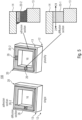
- Fig. 5 shows a schematic 3D view of an package 100 for an optical radiation device 10 together with an enlarged cross-sectional view of the bond structure 20 according to a further embodiment.
- the adhesive layer 20-2 comprises a gas diffusion section 26 for providing the gas diffusion path 24 through the bond structure 20.
- the diffusion section 26 may be formed as at least one channel 26 or a plurality of channels 26 through the adhesive layer 20-2 and comprises a gas diffusive material.
- the diffusion section 26 may comprise a gas diffusive filler material or gas diffusive filler particles embedded in the adhesive layer 20-2.
- the section 26 of the adhesive layer 20-2 which laterally extends through the bond structure 20, comprises the gas diffusive filler material or gas diffusive filler particles and forms the diffusion path 24.
- a plurality of sections of the adhesive layer 20-2, which laterally extend through the bond structure 20, may comprise the gas diffusive filler material or gas diffusive filler particles and may form the diffusion path 24.
- the diffusion layer 20-1 does not fully surround the interface (bond structure) 20 but is partially formed as a section 26 of the bond structure 20.
- the diffusion section(s) 26 in the adhesion section (layer) 20-2 at least one or a plurality of diffusion channels 24 are formed through the adhesion layer(s) 20-2.
- Fig. 6 shows a schematic cross-sectional view through an acoustic type package for an optical radiation device 10 according to a further embodiment together with an enlarged view of the bond structure 20.
- the adhesive layer (filler adhesive) 20-2 of the bond structure 20 may comprise gas diffusive filler particles 25 (filler particles which are diffusive for the gas G CAV ) for providing the diffusion path 24 through the bond structure 20.
- the adhesive layer 20-2 may comprise a PTFE material or a PTFE impregnated adhesive for providing the diffusion path 24 of the gas G CAV through the bond structure 20.
- the diffusion time constant T D can be set to a predefined value.
- the more filler particles in the adhesive layer 20-2 and the greater the dimension (e.g., the vertical cross sectional area) of the adhesive layer 20-2 the shorter is said diffusion time constant T D .
- the adhesive layer 20-2 of the bond structure 20 may comprise diffusion time enhancing filter particles 25, e.g., in a standard adhesive material.
- the filler particles 25, e.g., PTFE material, allow a quicker diffusion of the gas G CAV by having a shorter effective path length of the glue interface (bond structure) 20 to the outside (ambient atmosphere).
- the package 100 uses a highly gas permeable structure or layer based on the filler particles 25) in the bond structure (interface) 20 of the cavity package 100.
- the present concept can be used in physical gas sensors, such as in photoacoustic spectroscopy (PAS) and non-dispersive infrared (NDIR) sensors.
- PAS photoacoustic spectroscopy
- NDIR non-dispersive infrared
- a potential method to improve the emitter performance is to make one element (the bond structure 20) of its construction 'breathable', i.e. allow exchange of gas, but not compromise acoustic tightness.
- An adhesive 20-2 used to retain the lid element 14, which forms or comprises an IR filter, in place can be used wherein the adhesive may contain a PTFE or a similar gas exchanging / high permeability filler material. This structure allows the exchange of gas (parasitic gas G CAV ) far more readily through the adhesive material.
- the high gas permeability material suspended in the adhesive 20-2 allows to provide an cavity 16, but still allow the transmission of gas both into and out of the emitter cavity 16.
- the gas exchanging material does not necessarily need to form a solid pathway between interior and exterior if the adhesive already has some ability to allow gas exchange, it needs to have a much higher rate of gas permeability. An improved gas transmission may also occur along the interfaces between the adhesive and the more gas permeable filler.
- the high gas permeability material in the adhesive 20-2 would allow equalization of (atmospheric) pressure between the IR emitter interior 16 and the gas measurement chamber (see Fig. 8a , for example) in which it sits. It would also allow any gas, e.g. CO 2 , generated from curing materials to escape. If the diffusion time of gas through the material (bond structure 20) is chosen to be much slower than that of the gas, e.g. CO 2 , entering the measurement chamber (see Fig. 8a , for example), the gas, e.g. CO 2 , measurement should not be affected.
- the high gas permeability impregnated adhesive 20-2 could potentially be cured by thermal means, since the adhesive material's breathability would allow pressure inside the ceramic cavity to equalize on cooling.
- the gas exchange through the high gas permeability material 20-1 may not be fast enough during thermal curing (during the manufacturing process) to overcome internal air pressure changes, so that a slow ramp in heating may applied.
- the adhesive 20-1 will not be pushed out of the joint between the base structure 12, e.g. a ceramic cavity, and the lid element 14, e.g. an IR filter, by internal air pressure, creating voids in the adhesive 20-1.
- the package may be formed as a ceramic cavity emitter package 100 and may comprise the optical radiation device 10 in form of an IR emitter (e.g. a MEMS heater) 10-1.
- the package 100 may be part of a PAS gas detector for detecting a target gas G TAR .
- the packaged emitter 10-1 is formed as a MEMS heater die on the base structure 12. The die is connected via wire-bonds 11 to a processing circuit (e.g. an ASIC). The light (radiation) emitted from the MEMS heater die 10-1 is transmitted to and through the transparent lid element 14.
- the led element 14 may comprise or form an IR filter (band-pass filter).
- the IR filter may be formed as a silicon IR filter so that filtered IR light emerges from the IR filter.
- the adhesive material 20-2 of the bond structure 20 retains the lid element (filter) 14 on the sidewalls of the (ceramic) cavity package 100.
- the package 100 may comprise an acoustically tight gas diffusion path 24, e.g. with an acoustically tight bond structure 20.
- the package 100 may be arranged as an acoustically tight package 100.
- the bond structure 20 may comprise a diffusion layer having a parasitic gas diffusive material or parasitic gas diffusive structure for providing an acoustically tight parasitic gas diffusion path 24 between the cavity 16 and the surrounding atmosphere 18.
- the fluid sensor 200 may comprise the package 100 for an optical radiation device 10.
- the fluid sensor 200 may be formed as a PAS gas detector (fluid detector) 200-1, wherein the optical radiation device 10 is an IR emitter or a laser or LED 10-1 and part of the PAS gas detector 200-1 for detecting a target gas G TAR .
- the bond structure 20 of the package 100 is arranged to provide the diffusion path 24 for a gas G CAV through the bond structure 20.
- the bond structure 20 of the package 100 may be arranged to provide an acoustically tight diffusion path 24 for a parasitic gas G PAR through the bond structure 20.
- the fluid sensor 200 may be formed as an NDIR gas detector 200-2, wherein the optical radiation device 10 is an optical radiation detector 10-2, e.g., a thermopile detector, for detecting a target gas G TAR , wherein the bond structure 20 is arranged to provide the diffusion path 24 for a gas G CAV through the bond structure 20.
- the optical radiation device 10 is an optical radiation detector 10-2, e.g., a thermopile detector, for detecting a target gas G TAR
- the bond structure 20 is arranged to provide the diffusion path 24 for a gas G CAV through the bond structure 20.
- Fig. 8a shows a schematic block diagram of a fluid (gas or liquid) sensing device 200-1 in the form of a PAS gas sensor having the package 100 for an optical radiation device 10 according to a further embodiment.
- the PAS gas sensor 200 comprises a light source 10-1 which is arranged in the package 100, e.g. an the acoustically tight package 100.
- the light source 10 may comprise an infrared emitter or a laser diode, for example.
- the light source 10 may be periodically chopped.
- the package 100 comprises an optical filter, which is, for example, part of the lid element 14, for a wavelength selection.
- the gas sensor device 200 further comprises a sample area (interaction area) 210 where the light or radiation R between the light source 10 and the detector 220 interacts with the environmental medium.
- the detector 220 may be formed, for example, as a (capacitive or piezoelectric) MEMS microphone.
- the molecules of the target gas G TAR e.g. CO 2 molecules, absorb the light R emitted from the light source 10 and filtered by the optical filter 14.
- the light absorption causes a periodic local change of temperature in the interaction area 210, which results in corresponding pressure changes in the interaction area 210.
- the periodic pressure changes are detected by the acoustic detector 220, e.g., a MEMS microphone, which is optimized for low frequency operation.
- the acoustic detector 220 may be read out by means of an ASIC 230, for example.
- the closed interaction area may be accessible through a fluid port 240 for fluid (gas or liquid) diffusion.
- embodiments may relate to a PTFE impregnated adhesive to secure of the lid element 14, e.g. an IR filter, to the base structure 12 defining a cavity 16, e.g. a ceramic cavity, on the PAS gas sensor 200-1, e.g. a PAS CO 2 sensor.
- a PTFE impregnated adhesive to secure of the lid element 14, e.g. an IR filter, to the base structure 12 defining a cavity 16, e.g. a ceramic cavity, on the PAS gas sensor 200-1, e.g. a PAS CO 2 sensor.
- Fig. 8b shows a schematic block diagram of a fluid (gas or liquid) sensing device in the form of an NDIR gas sensor 200-2 having the package 100 for an optical radiation device 10 according to a further embodiment.
- the NDIR sensor device 200-2 comprises a radiation source 250, the package 100 for the detector 10-2, the package 100 comprises the lid element 14 having filter element for a wavelength selection and the sample area (interaction area) 210 which is accessible by means of a gas inlet/outlet 240.
- the interaction area 210 the light R between the light source 250 and the detector 10 interacts with the environmental medium, e.g. the target gas G TAR .
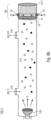
- the main components of the NDIR sensor 200-2 are an infrared IR source 250, the sample chamber or light tube 210, the light filter 14 and the infrared detector 10 in the package 100.
- the IR light R is directed through the sample chamber 210 towards the packaged detector 10.
- the target gas G TAR in the sample chamber 210 causes an absorption of a specific wavelength and the intensity change at this wavelength is measured by the detector 10 to determine the target gas concentration.
- the optical filter 14 in front of (upstream to) the detector is arranged to eliminate all light except the wavelength that the target gas molecules can absorb.
- the bond structure 20 of the package 100 may be arranged to provide an acoustically tight diffusion path 24 for a parasitic gas G PAR through the bond structure 20.
- Embodiments describe an improvement to existing cavity packages for gas sensing, which often contain a certain amount of the target gas interfering with the IR radiation as gas G CAV .
- a defined gas ventilation path 24 is provided inside the cavity package 100, wherein the cavity package 100 allows gas G CAV (parasitic gas) to penetrate at a specific rate.
- the cavity package 100 may be acoustically tight but also allows gas G CAV (parasitic gas) to penetrate at a specific rate.
- the ventilation path 24 can be formed as one or more separate (diffusion) layers or a diffusion material 20-1 embedded into existing adhesive layers 20-2 and/or 20-3.
- the package 100 for an optical radiation device 100 may provide a drift stabilization of a gas sensing device 200, e.g., a PAS system 200-1 or a NDIR system 200-2 for gas sensing.
- a gas sensing device 200 e.g., a PAS system 200-1 or a NDIR system 200-2 for gas sensing.
- the package 100 is inexpensive to manufacture, wherein there is no need to have the gas content fully settled and under control prior to calibration of the gas sensor device.
- the bond structure 20 can inexpensively be integrated in the package.
- the package 100 provides a defined acoustical tightness for the gas sensor device 200, e.g., a PAS sensor 200-1 or an NDIR sensor 200-2, so that the package 100 can be inexpensively integrated into the measurement cell.
- the package 100 can be formed to have high mechanical robustness as well as high resilience to temperature cycles.
- a package for an optical radiation device comprises a base structure having arranged thereon the optical radiation device, an optically (IR, UV or visible radiation) transparent lid element bonded to the base structure defining a cavity between the base structure and the lid element, and a bond structure in a bonding region between the base structure and the lid element, wherein the bond structure is arranged to provide an adhesive bond between the base structure and the lid element, and wherein the bond structure comprises a diffusion layer having a gas diffusive material or gas diffusive structure for providing a gas diffusion path between the closed cavity and the surrounding atmosphere.
- the optical radiation device is an optical radiation emitter or an optical radiation detector.
- the package is acoustically tight and comprises an acoustically tight gas diffusion path.
- the bond structure may comprise a diffusion layer having a parasitic gas diffusive material or parasitic gas diffusive structure for providing an acoustically tight parasitic gas diffusion path between the cavity and the surrounding atmosphere.
- the optical radiation device is an IR emitter and part of a PAS gas detector for detecting a target gas, wherein the bond structure is arranged to provide an acoustically tight diffusion path for a gas through the bond structure.
- the optical radiation device is an optical radiation detector and part of a NDIR gas detector for detecting a target gas, wherein the bond structure is arranged to provide the diffusion path for a gas through the bond structure.
- the bond structure is arranged to have a gas permeability for providing a gas exchange through the diffusion path between the cavity and the surrounding environment with a diffusion time constant which is below 600, 300, 100 or 10 seconds.
- the bond structure comprises an adhesive layer in the bonding region for providing the adhesive bond between the base structure and the lid element.
- the adhesive layer comprises gas diffusive filler particles for providing the diffusion path through the bond structure.
- the adhesive layer comprises a PTFE material or a PTFE impregnated adhesive for providing the diffusion path of the target gas through the bond structure.
- the adhesive layer comprises a gas diffusion section for providing the gas diffusion path through the bond structure.
- the diffusion section is formed as at least one channel through the adhesive layer and comprises a gas diffusive material.
- the diffusion section comprises a gas diffusive filler material or gas diffusive filler particles embedded in the adhesive layer.
- the bond structure further comprises a further adhesive layer, wherein the diffusion layer having a gas diffusive material is sandwiched between the adhesive layer and the further adhesive layer.
- At least one of the base structure and the lid element further comprises a supporting structure, e.g. in form of a merlon-like structure, for mechanically stabilizing the diffusion layer.
- the bond structure comprises a stack of a plurality of alternating adhesive and parasitic gas diffusive layers.
- the package further comprises an intermediate wall structure between the base structure and the lid element, wherein a further bond structure is arranged in a further bond region between the intermediate wall structure and the lid element, and wherein the bond structure is arranged in the bond region between the intermediate wall structure and the base structure, or wherein a further bond structure is arranged in a further bond region between the intermediate wall structure and the base structure, and wherein the bond structure is arranged in the bond region between the intermediate wall structure and the lid element.
- a fluid sensor comprises the package for an optical radiation device.
- the fluid sensor is a PAS gas detector
- the optical radiation device is an IR emitter and part of the PAS gas detector for detecting a target gas
- the bond structure is arranged to provide an acoustically tight diffusion path for a gas through the bond structure.
- the fluid senor is a NDIR gas detector
- the optical radiation device is an optical radiation detector and part of the NDIR gas detector for detecting a target gas
- the bond structure is arranged to provide the diffusion path for a gas through the bond structure.
Landscapes
- Physics & Mathematics (AREA)
- Spectroscopy & Molecular Physics (AREA)
- General Physics & Mathematics (AREA)
- Life Sciences & Earth Sciences (AREA)
- Health & Medical Sciences (AREA)
- Chemical & Material Sciences (AREA)
- Analytical Chemistry (AREA)
- Biochemistry (AREA)
- General Health & Medical Sciences (AREA)
- Immunology (AREA)
- Pathology (AREA)
- Engineering & Computer Science (AREA)
- Microelectronics & Electronic Packaging (AREA)
- Computer Hardware Design (AREA)
- Investigating Or Analysing Materials By Optical Means (AREA)
Abstract
Description
- Embodiments relate to a package for an optical radiation device, e.g. for an optical radiation source (emitter) or an optical radiation detector. More specifically, embodiments relate a package for an optical radiation device having a high gas diffusivity interface. Thus, embodiments relate to high gas diffusivity interfaces for cavity packages.
- The sensing of environmental parameters in the ambient atmosphere, such as noise, sound, temperature and gases, e.g. environmental gas components, gains more and more importance in the implementation of appropriate sensors within mobile devices, home automation, such as smart home, the automotive sector, etc. With the evermore extensive use of sensors, there is also a particular need to be able to provide such sensors, e.g. for sensing the environmental air quality, and their components as inexpensively as possible, but nevertheless the achieved reliability and accuracy of the sensors should be as high as possible.
- In the field of monitoring the air quality in our environment, there are several types of existing gas-sensing concepts, for example, NDIR sensors (NDIR = non-dispersive infrared), chemical sensors, catalytic bead (pellistor) sensors and photo-acoustical sensors (PAS sensors, PAS = photoacoustic spectroscopy). An often used sensor principle is based on the excitation of gas molecules in a medium by (e.g. infrared) light with a certain wavelength. However, currently available NDIR or PAS systems are relatively expensive due to their complex setups or special components even if the NDIR or PAS devices offer a relatively high sensitivity together with a relatively cheap set of components. Furthermore, chemical sensors are showing a relatively poor selectivity compared to single-wavelength or filter containing optical systems.
- A typical optical sensor, e.g. a PAS or NDIR sensor, comprises a radiation source, filter elements for a wavelength selection, a detector and the sample area (interaction area) where the light between the light source and the detector interacts with the environmental medium.
- The inventors of the present application have recognized that depending on the target gas (the gas to be measured), e.g. CO2, a parasitic content of this gas (or of another gas) inside the emitter (PAS) package or the detector (NDIR) package would affect the sensitivity of such a sensor toward the target gas. The presence of a parasitic gas, such as CO2, e.g. in the emitter or detector, forms relatively easy due to temperature steps, such as bake and reflow process steps, applied to the gas sensor system during the manufacturing process.
- Thus, it is an object of the herewith disclosed principle to provide an improved package for an optical radiation device, e.g. an optical radiation source as part of a PAS sensor or an optical radiation detector as part of an NDIR sensor, for achieving improved operating characteristics of the optical radiation device and of the sensor device comprising the optical radiation device.
- Such a need can be solved by the acoustically tight package for an optical radiation device according to claim 1.
- Further specific implementations of the package are defined in the dependent claims.
- According to an embodiment, a package for an optical radiation device comprises a base structure having arranged thereon the optical radiation device, an optically (IR, UV or visible radiation) transparent lid element bonded to the base structure defining a cavity between the base structure and the lid element, and a bond structure in a bonding region between the base structure and the lid element. The bond structure is arranged to provide an adhesive bond between the base structure and the lid element, and the bond structure comprises a diffusion layer having a gas diffusive material or gas diffusive structure for providing an gas diffusion path between the closed cavity and the surrounding atmosphere. According to an embodiment, the optical radiation device is an optical radiation emitter or an optical radiation detector.
- Thus, the present concept as described in the different embodiments can be used in physical gas sensors, such as in photoacoustic spectroscopy (PAS) and non-dispersive infrared (NDIR) gas sensors. According to embodiments, the present concept improves a sub-component of these systems, such as the emitter (for a PAS sensor) or the detector (for the NDIR sensor).
- Thus, the present disclosure describes a design of a package that has a defined diffusion path to allow an out-diffusion of gases inside an emitter (for a PAS sensor) or a detector (for an NDIR sensor). A defined exchange with the ambient air will be used to further dilute the gas inside the emitter/detector package. Thus, only a (highly) reduced amount of a gas remains in the package of the optical radiation device.
- According to embodiments, the package may comprises an acoustically tight gas diffusion path, e.g. with an acoustically tight bond structure. Thus, the package may be arranged to be acoustically tight. Further, the bond structure may comprise a diffusion layer having a "parasitic" gas diffusive material or parasitic gas diffusive structure for providing an acoustically tight parasitic gas diffusion path between the cavity and the surrounding atmosphere. Any gas which negatively influences or affects the operation of the optical radiation device may be regarded as a parasitic gas, i.e. a gas or gas composition, which has a negative effect to the functionality of the optical radiation structure.
- An acoustically tight package may ensure that the cavity is acoustically isolated from the sample area (interaction area) in the measurement cell of a sensor device. Moreover, acoustical influences or interferences from the environment, e.g. in the frequency range of the periodically chopped radiation emitted from the (PAS) radiation source, may be sufficiently attenuated and suppressed, i.e. acoustically kept away from the cavity of the package.
- Once the gas (or parasitic gas) is fully driven out and/or at the same level (equilibrium) with the ambient gas concentration (or ambient parasitic gas concentration), the device can be calibrated. A further increase of gas, e.g. due to operation, will be avoided due to the constantly given diffusivity of the package.
- According to embodiments, the package for an optical radiation device uses a highly gas permeable layer (diffusion layer) in the interface (having a high gas diffusivity) of a cavity package which is typically closed by an optical filter (lid element). This diffusion layer can be integrated in front-end or back-end on the filter or on the cavity package directly. To seal off the package, an adhesive layer is commonly used. According to embodiments, there could be also filter particles directly integrated into the adhesive to modify its diffusion properties.
- Thus, embodiments of the package having the high gas diffusivity interface can achieve the following technical effects.
- The package can avoid that an elevated amount of the gas, e.g. a parasitic gas such as CO2, is present inside the emitter package during the sensor calibration, wherein an elevated amount of the gas can quickly diffuse out of the package. Thus, it can be prevented that a gas will cause a drift of the sensor toward lower concentrations detected in case of an emitter in a PAS system, for example. Thus, it can be avoided that a gas (e.g. CO2) inside the PAS emitter package would reduce the radiation output by light absorption. Thus, the gas sensitivity of the PAS sensor is not lowered as it can be avoided that less radiation reaches the interaction area of the sensor cell.
- Moreover, it can be avoided during assembling and operating the emitter, e.g. a ceramic emitter, that the air pressure within the sealed cavity becomes too low due to curing the lid adhesive (filter adhesive) at a high temperature as the air pressure falls within the cavity on cooling.
- In case, UV cured adhesive are used for the lid (filter) attachment and a contamination occurred due to uncured adhesive material in the (ceramic) cavity, interfering shifts in the (ceramic) emitter output signal can be avoided as the (parasitic) gas content, e.g. CO2, which results from the contamination, can easily diffuse to the environment.
- Moreover, the package can avoid that an elevated amount of the (parasitic) gas, e.g. CO2, is present inside the detector package during the sensor calibration, wherein an elevated amount of the gas can quickly diffuse out of the package. Thus, it can be prevented that a gas will cause a drift of the sensor toward higher concentrations in a detector of a NDIR system. Thus, it can be avoided that a gas, e.g. a parasitic gas, such as CO2, inside the NDIR detector package would reduce the received radiation due to light absorption. Thus, the gas sensitivity (CO2 sensitivity) is not lowered as it can be avoided that less radiation reaches the radiation detector.
- In the following, embodiments of the present disclosure are described in the following in more detail while making reference to the accompanying drawings in which:
- Fig. 1
- shows a schematic cross-sectional view through a package for an optical radiation device according to an embodiment;
- Fig. 2a-d
- show schematic cross-sectional views through a package for an optical radiation device according to further embodiments;
- Fig. 3a-d
- show schematic cross-sectional views through a package for an optical radiation device together with an enlarged cross-sectional view of the bond structure according to further embodiments;
- Figs. 4
- shows a schematic cross-sectional view of the package for an optical radiation device together with an enlarged cross-sectional view of the bond structure according to a further embodiment;
- Fig. 5
- shows a schematic 3D view of the package for an optical radiation device together with an enlarged cross-sectional view of the bond structure according to a further embodiment;
- Figs. 6
- shows a schematic cross-sectional view of the package for an optical radiation device together with an enlarged cross-sectional view of the bond structure according to a further embodiment;
- Fig. 7
- shows a schematic block diagram of a fluid (= gas or liquid) sensing device having the package for an optical radiation device according to a further embodiment;
- Fig. 8a
- shows a schematic block diagram of a fluid (= gas or liquid) sensing device in form of a PAS gas senor having the (e.g. acoustically tight) package for an optical radiation device according to a further embodiment; and
- Fig. 8b
- shows a schematic block diagram of a fluid (= gas or liquid) sensing device in form of a NDIR gas sensor having the package for an optical radiation device according to a further embodiment.
- In the following description, embodiments are discussed in further detail using the figures, wherein in the figures and the specification identical elements and elements having the same functionality and/or the same technical or physical effect are provided with the same reference numbers or are identified with the same name. Thus, the description of these elements and of the functionality thereof as illustrated in the different embodiments are mutually exchangeable or may be applied to one another in the different embodiments.
- In the following description, embodiments are discussed in detail, however, it should be appreciated that the embodiments provide many applicable concepts that can be embodied in a wide variety of semiconductor devices. The specific embodiments discussed are merely illustrative of specific ways to make and use the present concept, and do not limit the scope of the embodiments. In the following description of embodiments, the same or similar elements having the same function have associated therewith the same reference signs or the same name, and a description of such elements will not be repeated for every embodiment. Moreover, features of the different embodiments described hereinafter may be combined with each other, unless specifically noted otherwise.
- In the description of the embodiments, terms and text passages placed in brackets (next to a described element or function) are to be understood as further explanations, exemplary or optionally configurations, exemplary additions and/or exemplary alternatives of the described element or function.
- It is understood that when an element is referred to as being "connected" or "coupled" to another element, it may be directly connected or coupled to the other element, or intermediate elements that may be present. Conversely, when an element is referred to as being "directly" connected to another element, "connected" or "coupled," there are no intermediate elements. Other terms used to describe the relationship between elements should be construed in a similar fashion (e.g., "between" versus "directly between", "adjacent" versus "directly adjacent", and "on" versus "directly on", etc.).
- For facilitating the description of the different embodiments, some of the figures comprise a Cartesian coordinate system x, y, z, wherein the x-y-plane corresponds, i.e. is parallel, to a main surface region (= a reference plane = x-y-plane), wherein the direction vertically up with respect to the reference plane (x-y-plane) corresponds to the "+z" direction, and wherein the direction vertically down with respect to the reference plane (x-y-plane) corresponds to the "- z" direction. In the following description, the term "lateral" means a direction parallel to the x- and/or y-direction or a direction parallel to (or in) the x-y-plane, wherein the term "vertical" means a direction parallel to the z-direction.
-
Fig. 1 shows a schematic cross-sectional view through anpackage 100 for an optical radiation device 10 (10-1, 10-2) according to an embodiment. As exemplarily shown inFig. 1 , thepackage 100 for theoptical radiation device 10 comprises abase structure 12 having arranged thereon theoptical radiation device 10, a lid element 14 (e.g. optically transparent for IR, UV or visible radiation) bonded to thebase structure 12 and defining acavity 16 between thebase structure 12 and thelid element 14. Thepackage 100 further comprises abond structure 20 in abonding region 22 between thebase structure 12 and thelid element 14. - The
bond structure 20 is arranged to provide an adhesive bond between thebase structure 12 and thelid element 14. Thebond structure 20 comprises a diffusion layer 20-1 having a gas diffusive material or gas diffusive structure for providing agas diffusion path 24 between theclosed cavity 16 and the surrounding atmosphere 18. According to an embodiment, theoptical radiation device 10 may be formed as an optical radiation emitter 10-1 or an optical radiation detector 10-2. - According to an embodiment, the
package 100 may comprise an acoustically tightgas diffusion path 24, e.g. with an acousticallytight bond structure 20. Thus, thepackage 100 may be arranged as an acousticallytight package 100. According to a further embodiment, thebond structure 20 may comprise a diffusion layer 20-1, 20-2 having a parasitic gas diffusive material or parasitic gas diffusive structure for providing an acoustically tight parasiticgas diffusion path 24 between thecavity 16 and the surrounding atmosphere 18. - In the context of the present description, the term "acoustically tight" may define a condition of the
package 100 and, for example, of thebond structure 20 of thepackage 100, wherein a first order low frequency (roll-off corner frequency or high-pass corner frequency) is (about) 0.01 Hz (or between 0.005 and 0,05 Hz). A first order low frequency (roll-off corner frequency) of (about) 0.01 Hz (within ± 10%) may result in an attenuation of 72 dB (equals a factor of 4000) at a target frequency of 40 Hz (within ± 5 Hz), for example. - Thus, the acoustically
tight package 100 may ensure that thecavity 16 is acoustically isolated from the sample area (interaction area) in the measurement cell of a sensor device (seeFig. 8a-b , for example). The periodically chopped radiation emitted from the (PAS) radiation source may be sufficiently attenuated and suppressed, i.e. acoustically kept away from the sample area (interaction area) in the measurement cell of a sensor device, to ensure that the gas measurements are not compromised. - Moreover, acoustical influences or interferences from the environment, e.g. in the frequency range of the periodically chopped radiation emitted from the (PAS) radiation source, may be sufficiently attenuated and suppressed, i.e. acoustically kept away from the
cavity 16 of thepackage 100. Thus, thecavity 16 of thepackage 100 may be acoustically isolated from the environment, e.g. from external noise. - In the context of the present description, the term "parasitic" gas may relate to any gas or gas composition, which affects or (negatively) influences the operation of the optical radiation device. Thus, a parasitic gas may be any gas or gas composition, which may have a negative effect to the functionality of the optical radiation structure.
- According to an embodiment, the
optical radiation device 10 may be an IR emitter (e.g. a MEMS heater) and, thus, part of a PAS gas detector (seeFig. 8a , for example) for detecting a target gas GTAR, wherein thebond structure 20 is arranged to provide thediffusion path 24 for a (parasitic) gas GCAV (from or to the cavity 16) through thebond structure 20. According to a further embodiment, theoptical radiation device 10 may be a laser or LED, e.g. a blue ray laser with an emission wavelength of 405 nm (CWL = continuous wave laser), for example. - According to an embodiment, the
optical radiation device 10 may be (alternatively) an optical radiation detector and part of a NDIR gas detector (e.g. a thermopile, seeFig. 8b , for example) for detecting a target gas GTAR, wherein thebond structure 20 is arranged to provide thediffusion path 24 for a parasitic gas GCAV through thebond structure 20. - Embodiments of the present disclosure are described with respect to gases or gas components, e.g., in the environmental air. However, the description of the different embodiments is equally applicable to liquids or liquid components in the environmental medium. Thus, the general term "fluid" may relate to a liquid or a gas. Moreover, the description with respect to a gas or gas component is equally applicable to a liquid or liquid component.
- Thus, a target gas or target gas component is the gas or gas component to be detected or sensed and may comprise at least one of CO, CO2, O3, NOx, methane, etc., for example. The present concept is equally applicable to sense a target liquid or a target liquid component in the environmental medium. In the context of the embodiments, the target gas GTAR and the parasitic gas GCAV may relate to the same gas or gas component or may relate to different gases or different gas components. According to an exemplarily embodiment, the target gas or target gas component to be detected or sensed and the (parasitic) gas GCAV may relate to gases or gas components having similar absorption lines (which are reactive on similar bands).
- To summarize, the gas (or parasitic gas) GCAV may relate to any gas content in the
cavity 16 which may affect an operating parameter, e.g. the sensitivity, of theoptical radiation device 10 or of a sensor device which comprises theoptical radiation device 10. Thus, the gas GCAV may be the target gas to be sensed or another component, e.g. water vapor, which will also vent out through thediffusion path 24. According to an exemplarily embodiment, the target gas or target gas component GTAR to be detected or sensed may comprise CO (carbon monoxide), for example, wherein the (parasitic) gas GCAV may comprise CO2 (carbon dioxide), because CO and CO2 have similar absorption lines (bands). Moreover, according to a further exemplarily embodiment, the target gas or target gas component to be detected or sensed may comprise CO2 (carbon dioxide), for example, wherein the (parasitic) gas GCAV may comprise CO (carbon monoxide). - According to an embodiment, the
bond structure 20 is arranged to have a permeability for the gas GCAV for providing a gas exchange (of gas GCAV) through thediffusion path 24 between the cavity and the surrounding environment with a diffusion time constant TD which is below 600, 300, 100 or 10 seconds or between 2 and 600, 300, 100, or 10 seconds. - The diffusion time constant TD is, in the context of the present description, the time duration until the gas GCAV is fully driven out of the package and/or at the same level (equilibrium) with the ambient gas concentration, such as the concentration of the gas GCAV in the environment. The diffusion time constant TD of the gas GCAV is based on the gas diffusivity or gas permeability along the
diffusion path 24 through thebond structure 20. As thebond structure 20 comprises the diffusion layer having a gas diffusive material or a gas diffusive structure (for the gas GCAV), thebond structure 20 allows the transmission of the gas GCAV in both directions, i.e., both into and out of the cavity 16 (to allow a gas exchange of the gas GCAV). - In general, the term "gas permeability" or "gas diffusivity" refers to the permeability of the
interface 20 to gas. The higher the gas diffusivity of the interface, for example, the better the interface can transport gas to the outside or release it back to the inside. The higher the gas diffusivity of theinterface 20, the shorter is the diffusion time constant TD. - According to an embodiment, the
bond structure 20 comprises the diffusion layer 20-1 and the adhesive layer 20-2 in the bonding region for providing the adhesive bond between thebase structure 12 and thelid element 14. The diffusion layer 20-1 may be formed as a layer which is highly permeable for the gas GCAV, for providing thediffusion path 24 of the gas GCAV through thebond structure 20, i.e., from thecavity 16 to the surrounding environment. - The diffusion layer 20-1 may comprise a gas diffusive material or a gas diffusive structure for the gas GCAV (e.g. in form of very thin pores or capillary tubes with an effective pore size or tube diameter in a range of about 1 µm and 30 µm) for providing the
diffusion path 24 between theclose cavity 16 and the surrounding atmosphere. The adhesive layer 20-2 may be formed as a double-sided tape which is attached to a side (surface region) of the diffusion layer 20-1, e.g., a PTFE layer or a PTFE impregnated adhesive materials, polymers, such as polyamide or cellulose acetate, or ceramic materials. The bond structure (bondline) 20 may comprise a typical overall thickness between (around) 30 µm and 100 µm, for example. - The
package 100 may comprise an exemplary lateral extension "X" between 2 mm and 8 mm, between 3 mm and 5 mm or of about 4 mm. The (lateral) thickness X13 of thewall 13 may be in a range of about 0.1 mm to 1 mm. - In case of a
bond structure 20 comprising the diffusion layer 20-1 and the adhesive layer 20-2, the diffusion layer 20-1 may comprise a thickness t20-1 in a range between 10 µm and 200 µm or between 30 µm and 100 µm, wherein the adhesive layer 20-2 may comprise a (vertical) thickness t20-2 of about 5 µm to 100 µm. The diffusion layer 20-1 and the adhesive layer 20-2 may comprise a (lateral) width w20-1, w20-2 of about 0.1 mm to 2 mm which corresponds to the (lateral) wall thickness X13. In case thebond structure 20 comprises the adhesive layer 20-2 with the filler particles, the (lateral) thickness t20-2 of the adhesive filler layer 20-2 is in a range between 5 µm and 100 µm. - Thus, according to an embodiment, the
bond structure 20 may comprises the diffusion layer 20-1 and the adhesive layer 20-2 in thebonding region 22 for providing thediffusion path 24 between thecavity 16 and the surrounding environment and for providing the adhesive bond between thebase structure 12 and thelid element 14. According to an embodiment, thebond structure 20 may further comprise a further adhesive layer 20-3, wherein the diffusion layer 20-1 having a gas diffusive material is sandwiched between the adhesive layer 20-2 and the further adhesive layer 20-3. According to a further embodiment, thebond structure 20 comprises a stack of a plurality of alternating adhesive layers 20-2 and (sandwiched) gas diffusive layers 20-1. - According to an embodiment, at least one of the
base structure 12 and thelid element 14 may further comprise a supportingstructure 28, e.g. in form of a merlon-like structure for mechanically stabilizing the diffusion layer 20-1. - According to an embodiment, the
bond structure 20 may comprise an adhesive layer 20-2 in thebonding region 22 for providing the adhesive bond between thebase structure 12 and thelid element 14. The adhesive layer (filler adhesive) 20-2 may comprise gasdiffusive filler particles 25 for providing thediffusion path 24 through thebond structure 20. According to an embodiment, the adhesive layer 20-2 may comprise a PTFE material or a PTFE impregnated adhesive for providing thediffusion path 24 of the gas GCAV through thebond structure 20. - Based on the size and quantity (density) of the gas
diffusive filler particles 25 in the adhesive layer 20-2 and based on the dimensions of the adhesive layer 20-2, the diffusion time constant TD can be set to a requested value. Thus, themore filler particles 25 in the adhesive layer 20-2 and the greater the dimension (e.g. the vertical cross-sectional area) of adhesive layer 20-2, the shorter is the (set) diffusion time constant TD. - According to an embodiment, the adhesive layer 20-2 may comprise a
gas diffusion section 26 for providing thegas diffusion path 24 through thebond structure 20. According to an embodiment, thediffusion section 26 may be formed as at least one (or a plurality of) channel(s) 26 through the adhesive layer 20-2 and comprises a gas diffusive material. - According to a further embodiment, the
diffusion section 26 in the adhesive layer 20-2 may comprise a gas diffusive filler material or gas diffusive filler particles embedded in the adhesive layer 20-2. Thus, a part (section) of the adhesive layer 20-2, which laterally extends through thebond structure 20, comprises the gas diffusive filler material or gas diffusive filler particles and forms thediffusion path 24. - Further, a plurality of
gas diffusion sections 26 of the adhesive layer 20-2, which laterally extend through thebond structure 20, may comprise the gas diffusive filler material or gas diffusive filler particles and may form thediffusion path 24. - In the following description of
Fig. 2a-d , essentially additions, differences or alternatives to the embodiments as shown inFig. 1 are discussed in detail. Thus, the above description with respect toFig. 1 is equally applicable to the further embodiments as described below. As elements having the same structure and/or function are provided with the same reference numbers or name, a detailed description of such elements will not be repeated for every embodiment. -
Fig. 2a-d show further schematic cross-sectional views through further possible implementations of thepackage 100 for anoptical radiation device 10 according to further embodiments. The further illustrations of thepackage 100 inFigs. 2a-d should show (and clarify) that the following evaluations of the present concept for thepackage 100 for anoptical radiation device 10 are equally applicable to different configurations (designs) of the respectively bondedbase structure 12 andlid element 14 and to different positions of thebonding region 22 with thebond structure 20 between thebase structure 12 and thelid element 14. - To be more specific, as shown in
Fig. 1 , the base structure (basis element) 12 may comprise the (vertically extending)side walls 13. As shown inFig. 2a , thelid element 14 may comprise the (vertically extending)side walls 13. As shown inFig. 2b , thebase structure 12 and the lid element may each comprises a part of the (vertically extending)side walls 13. In each case, thebonding region 22 with the bond structure is formed between thebase structure 12 and thelid element 14. Thus, thelid element 14 is placed (arranged) on top of thebase structure 12. - Moreover, the following evaluations of the present concept for the
package 100 are also applicable to configurations with further "intermediate elements" in thebase structure 12, thelid element 14 and/or theside walls 13 as far as the intermediate elements are bonded to thebase structure 12, thelid element 14 and/or theside walls 13 and provide for thepackage 100. - Moreover, the
bond structure 20 may be formed (placed) at any height position of theside walls 13, e.g. at a top position as shown inFig. 1 , at a bottom position as shown inFig. 2a or at an intermediate position as shown inFig. 2b . Moreover, thebond structure 20 may be circumferentially arranged in theside walls 13 and parallel to the lateral (reference) plane, for example, for facilitating the manufacturing process. - As shown in
Fig. 2c , theside wall 13 of thepackage 100 is arranged between and adhesively fixed (bonded) to the base structure (base element) 12 and the lid element (lid structure) 14. As shown inFig. 2c , afurther bond structure 21 may arranged in afurther bond region 23 between theside wall 13 and thelid element 14, wherein thebond structure 20 is arranged in thebond region 22 between theside wall 13 and thebase structure 20. Thebond region 22 and thefurther bond region 23 are vertically spaced from each other. Thus, thefurther bond region 23 may be formed (placed) at a bottom position of the side wall(s) 13 as shown inFig. 2c . Alternatively, a least one (or both) of thebond region 20 and thefurther bond region 21 may be placed at an intermediate position of the side wall(s) 13. - As shown in
Fig. 2d , thefurther bond structure 21 may alternatively arranged in afurther bond region 23 between theside wall 13 and thebase structure 12, wherein thebond structure 20 is arranged in thebond region 22 between theside wall structure 13 and thelid element 14. Thebond region 22 and thefurther bond region 23 are vertically spaced from each other. Thus, thefurther bond region 23 may be formed (placed) at a top position of the side wall(s) 13 as shown inFig. 2d . Alternatively, a least one (or both) of thebond region 22 and thefurther bond region 23 may be placed at an intermediate position of the side wall(s) 13. - According to a further embodiment, the
bond structure 20 and thefurther bond structure 21 may form together thediffusion paths 24, 24-1. Thus, thefurther bond structure 21 may comprise an adhesive layer 21-2 in thefurther bonding region 23 for providing the adhesive bond. According to a further embodiment, the adhesive layer 21-2 of the further bond structure may comprise gasdiffusive filler particles 25 for providing a further diffusion path 24-1 through thebond structure 20. According to an embodiment, the adhesive layer 21-2 may comprise a PTFE material or a PTFE impregnated adhesive for providing the further diffusion path 24-1 of the target gas GTAR through thefurther bond structure 21. - According to a further embodiment, the
further bond structure 21 may comprise a diffusion layer 21-1 having a gas diffusive material or gas diffusive structure for providing a further gas diffusion path 24-1 between theclosed cavity 16 and the surrounding atmosphere. Thefurther bond structure 21 may comprise the adhesive layer 21-2 in thefurther bonding region 23 for providing the adhesive bond. - Thus, the
further bond structure 21 may comprise the same arrangement and function as thebond structure 20 for providing the further gas diffusion path 24-1. - Thus, the embodiments as discussed with respect to
Figs. 1 and2a-d describe a design of apackage 100 that has a defined gas diffusion path 24 (24-1) to allow an out-diffusion of gases inside anoptical radiation device 10, e.g. an emitter (PAS) 10-1 or a detector (NDIR) 10-2. A defined exchange with the ambient atmosphere, e.g. environmental air, will be used to further and further dilute the gas GCAV inside the emitter /detector package 100. - The
package 100 may be part of a gas sensor device (seeFigs. 7 and8a-b ). Once the gas GCAV is fully driven out and/or at the same level as (in an equilibrium with) the ambient gas concentration, the sensor device can be calibrated. A further increase of gas GCAV (e.g. due to operation) will be avoided due to the constantly given diffusivity of thepackage 100 through thebond structure 20 providing thediffusion path 24 between thecavity 16 and the surrounding atmosphere. - Depending on the material and geometry selection for the
bond structure 20, quick diffusion time constants (seconds / minutes) can be achieved by the interface layer stack which forms thebond structure 20. A gas GCAV will diffuse quickly inside the emitter /detector package 100 and can be calibrated out as it will be present in the sensor cell (sensor device) and in the emitter /detector package 100 in equal amount. - According to the described embodiments, the
package 100 uses a highly gas permeable structure or layer ("diffusion structure or layer" 21) in the interface (= bond structure = interface having a high gas diffusivity) 20 of thecavity package 100. Thecavity 16 is enclosed by thebase structure 12 and the lid element (lid structure) 14, wherein thelid element 14 may form or comprise an optical filter, for example. This diffusion layer (of the bond structure) 20 can be integrated in front- or backend on the lid structure (e.g. a filter) 14 orbase structure 12 of thecavity package 100 directly. To seal off thepackage 100, thebond structure 20 may comprise an adhesive layer (or layer stack). Alternatively, there could be filler particles directly integrated into the adhesive layer to modify its diffusion properties. - In the following description, further alternative embodiments are discussed in detail. Thus, the above description with respect to
Fig. 1 and2a-d is equally applicable to the further embodiments as described below. As elements having the same structure and/or function are provided with the same reference numbers or name, a detailed description of such elements will not be repeated for every embodiment. -
Fig. 3a-d show schematic cross-sectional views through an acoustically tight package for an optical radiation device according to further embodiments together with an enlarged sectional view of the bond structure. As shown inFigs. 3a-d , thebond structure 20 may comprises (at least) the diffusion layer 20-1 and the adhesive layer 20-2 in thebonding region 22 for providing thediffusion path 24 between thecavity 16 and the surrounding environment and for providing the adhesive bond between thebase structure 12 and thelid element 14. - As shown in
Fig. 3a , the diffusion layer 20-1 is attached to thelid element 14, wherein the adhesive layer is attached to thewall element 13 of thebase structure 12. Further, the opposing surfaces of the diffusion layer 20-1 and the adhesive layer 20-2 are attached to each other to form thebond structure 20. - As shown in
Fig. 3b , the diffusion layer 20-1 is attached to thewall element 13 of thebase structure 12, wherein the adhesive layer is attached to thelid element 14. Further, the opposing surfaces of the adhesive layer 20-2 and of the diffusion layer 20-1 are attached to each other to form thebond structure 20. - As shown in
Fig. 3c thebond structure 20 may be formed as a triple stack with adhesive layers 20-2 and 20-3 of both sides of the diffusion layer 20-1. Thus, according toFig. 3c , thebond structure 20 may further comprise the further adhesive layer 20-3, wherein the diffusion layer 20-1 having a gas diffusive material is sandwiched between the adhesive layer 20-2 and the further adhesive layer 20-3. - As shown in
Fig. 3d , thebond structure 20 may comprise a stack of a plurality of alternating adhesive layers 20-2 and diffusion layers 20-1. As exemplarily shown inFig. 3-d , each diffusion layer 20-1 is sandwiched between two adhesive layers 20-2, 20-3, for example. -
Fig. 4 shows a schematic cross-sectional view through an package for an optical radiation device according to a further embodiment together with an enlarged sectional view of the bond structure. As shown inFig. 4 , at least one of thebase structure 12 and thelid element 14 may further comprise a supportingstructure 28, e.g., in the form of a merlon- or pinnacle-like structure or of bumps, for mechanically stabilizing the diffusion layer 20-1. The supporting or stabilization structure may be part of thebase structure 12 or thelid element 14 or of both. InFig. 4 , thestabilization structure 28 is shown as part of thebase structure 12 on top of thewall elements 13. Thestabilization structures 28 are arranged to avoid a deflection of the lid element 14 (having an optical filter, for example) in case the diffusion layer 20-1 comprises a (relatively) soft and deformable material, e.g., a foam-like material. - To summarize, if the diffusion layer 20-1 comprises, for example, a soft foam-like material, the merlon-like structures around the package frame (between the
base structure 12 and the lid element 14) are arranged to stabilize the assembly by offering direct mechanical contact between thebase structure 12 and the adhesive layer 20-2 which is attached to thelid element 14, for example, or between thebase structure 12 and thelid element 14. - Alternatively, the merlon-like structures may be formed at the lid element and may provide direct mechanical contact to the adhesive layer 20-2 which is attached to the top side of the
wall elements 13 of thebase structure 12, or directly to thewall elements 13 of thebase structure 12. -
Fig. 5 shows a schematic 3D view of anpackage 100 for anoptical radiation device 10 together with an enlarged cross-sectional view of thebond structure 20 according to a further embodiment. - As shown in
Fig. 5 , the adhesive layer 20-2 comprises agas diffusion section 26 for providing thegas diffusion path 24 through thebond structure 20. According to the embodiment, thediffusion section 26 may be formed as at least onechannel 26 or a plurality ofchannels 26 through the adhesive layer 20-2 and comprises a gas diffusive material. According to a further embodiment, thediffusion section 26 may comprise a gas diffusive filler material or gas diffusive filler particles embedded in the adhesive layer 20-2. Thus, thesection 26 of the adhesive layer 20-2, which laterally extends through thebond structure 20, comprises the gas diffusive filler material or gas diffusive filler particles and forms thediffusion path 24. Further, a plurality of sections of the adhesive layer 20-2, which laterally extend through thebond structure 20, may comprise the gas diffusive filler material or gas diffusive filler particles and may form thediffusion path 24. - To summarize, the diffusion layer 20-1 does not fully surround the interface (bond structure) 20 but is partially formed as a
section 26 of thebond structure 20. By introducing the diffusion section(s) 26 in the adhesion section (layer) 20-2, at least one or a plurality ofdiffusion channels 24 are formed through the adhesion layer(s) 20-2. -
Fig. 6 shows a schematic cross-sectional view through an acoustic type package for anoptical radiation device 10 according to a further embodiment together with an enlarged view of thebond structure 20. - As exemplarily shown in
Fig. 6 , the adhesive layer (filler adhesive) 20-2 of thebond structure 20 may comprise gas diffusive filler particles 25 (filler particles which are diffusive for the gas GCAV) for providing thediffusion path 24 through thebond structure 20. According to an embodiment, the adhesive layer 20-2 may comprise a PTFE material or a PTFE impregnated adhesive for providing thediffusion path 24 of the gas GCAV through thebond structure 20. Based on the amount and quantity (density) of the gasdiffusive filler particles 25 in the adhesive layer 20-2, and based on the dimensions of the adhesive layer 20-2, the diffusion time constant TD can be set to a predefined value. Thus, the more filler particles in the adhesive layer 20-2 and the greater the dimension (e.g., the vertical cross sectional area) of the adhesive layer 20-2, the shorter is said diffusion time constant TD. - To summarize, the adhesive layer 20-2 of the
bond structure 20 may comprise diffusion time enhancingfilter particles 25, e.g., in a standard adhesive material. Thefiller particles 25, e.g., PTFE material, allow a quicker diffusion of the gas GCAV by having a shorter effective path length of the glue interface (bond structure) 20 to the outside (ambient atmosphere). - Thus, according to the above embodiments, the
package 100 uses a highly gas permeable structure or layer based on the filler particles 25) in the bond structure (interface) 20 of thecavity package 100. As further indicated above, the present concept can be used in physical gas sensors, such as in photoacoustic spectroscopy (PAS) and non-dispersive infrared (NDIR) sensors. The following evaluations are outlined in connection with a PAS gas sensor, however, the following evaluations are equally applicable to an NDIR gas sensor. - In the following, some technical effects of the
package 100 for anoptical radiation device 10 in form of anoptical radiation source 10, e.g. as part of a PAS sensor, are summarized. The following evaluations are correspondingly applicable to thepackage 100 for anoptical radiation device 10 in form of an optical radiation detector for a NDIR gas detector. - According to embodiments, a potential method to improve the emitter performance is to make one element (the bond structure 20) of its construction 'breathable', i.e. allow exchange of gas, but not compromise acoustic tightness. An adhesive 20-2 used to retain the
lid element 14, which forms or comprises an IR filter, in place can be used wherein the adhesive may contain a PTFE or a similar gas exchanging / high permeability filler material. This structure allows the exchange of gas (parasitic gas GCAV) far more readily through the adhesive material. - The high gas permeability material suspended in the adhesive 20-2 allows to provide an
cavity 16, but still allow the transmission of gas both into and out of theemitter cavity 16. The gas exchanging material does not necessarily need to form a solid pathway between interior and exterior if the adhesive already has some ability to allow gas exchange, it needs to have a much higher rate of gas permeability. An improved gas transmission may also occur along the interfaces between the adhesive and the more gas permeable filler. - The high gas permeability material in the adhesive 20-2 would allow equalization of (atmospheric) pressure between the
IR emitter interior 16 and the gas measurement chamber (seeFig. 8a , for example) in which it sits. It would also allow any gas, e.g. CO2, generated from curing materials to escape. If the diffusion time of gas through the material (bond structure 20) is chosen to be much slower than that of the gas, e.g. CO2, entering the measurement chamber (seeFig. 8a , for example), the gas, e.g. CO2, measurement should not be affected. - As well as UV curing, the high gas permeability impregnated adhesive 20-2 could potentially be cured by thermal means, since the adhesive material's breathability would allow pressure inside the ceramic cavity to equalize on cooling.
- However, the gas exchange through the high gas permeability material 20-1 may not be fast enough during thermal curing (during the manufacturing process) to overcome internal air pressure changes, so that a slow ramp in heating may applied. Thus, it can be ensured that the adhesive 20-1 will not be pushed out of the joint between the
base structure 12, e.g. a ceramic cavity, and thelid element 14, e.g. an IR filter, by internal air pressure, creating voids in the adhesive 20-1. - As exemplarily shown in
Figs. 1 to 6 , the package may be formed as a ceramiccavity emitter package 100 and may comprise theoptical radiation device 10 in form of an IR emitter (e.g. a MEMS heater) 10-1. Thus, thepackage 100 may be part of a PAS gas detector for detecting a target gas GTAR. According to an embodiment, the packaged emitter 10-1 is formed as a MEMS heater die on thebase structure 12. The die is connected via wire-bonds 11 to a processing circuit (e.g. an ASIC). The light (radiation) emitted from the MEMS heater die 10-1 is transmitted to and through thetransparent lid element 14. The ledelement 14 may comprise or form an IR filter (band-pass filter). The IR filter may be formed as a silicon IR filter so that filtered IR light emerges from the IR filter. The adhesive material 20-2 of thebond structure 20 retains the lid element (filter) 14 on the sidewalls of the (ceramic)cavity package 100. - According to the embodiment of
Figs. 1 to 6 , thepackage 100 may comprise an acoustically tightgas diffusion path 24, e.g. with an acousticallytight bond structure 20. Thus, thepackage 100 may be arranged as an acousticallytight package 100. According to a further embodiment, thebond structure 20 may comprise a diffusion layer having a parasitic gas diffusive material or parasitic gas diffusive structure for providing an acoustically tight parasiticgas diffusion path 24 between thecavity 16 and the surrounding atmosphere 18. -
Fig. 7 shows a schematic block diagram of a fluid (= gas or liquid)sensing device 200 having thepackage 100 for anoptical radiation device 10 according to a further embodiment. Thefluid sensor 200 may comprise thepackage 100 for anoptical radiation device 10. - According to an embodiment, the
fluid sensor 200 may be formed as a PAS gas detector (fluid detector) 200-1, wherein theoptical radiation device 10 is an IR emitter or a laser or LED 10-1 and part of the PAS gas detector 200-1 for detecting a target gas GTAR. Thebond structure 20 of thepackage 100 is arranged to provide thediffusion path 24 for a gas GCAV through thebond structure 20. According to an embodiment, thebond structure 20 of thepackage 100 may be arranged to provide an acousticallytight diffusion path 24 for a parasitic gas GPAR through thebond structure 20. - According to a further embodiment, the
fluid sensor 200 may be formed as an NDIR gas detector 200-2, wherein theoptical radiation device 10 is an optical radiation detector 10-2, e.g., a thermopile detector, for detecting a target gas GTAR, wherein thebond structure 20 is arranged to provide thediffusion path 24 for a gas GCAV through thebond structure 20. -
Fig. 8a shows a schematic block diagram of a fluid (gas or liquid) sensing device 200-1 in the form of a PAS gas sensor having thepackage 100 for anoptical radiation device 10 according to a further embodiment. - As shown in
Fig. 8a , thePAS gas sensor 200 comprises a light source 10-1 which is arranged in thepackage 100, e.g. an the acousticallytight package 100. Thelight source 10 may comprise an infrared emitter or a laser diode, for example. Thelight source 10 may be periodically chopped. Thepackage 100 comprises an optical filter, which is, for example, part of thelid element 14, for a wavelength selection. Thegas sensor device 200 further comprises a sample area (interaction area) 210 where the light or radiation R between thelight source 10 and thedetector 220 interacts with the environmental medium. Theoptical filter 14 is arranged to filter the wavelength related to a specific gas, e.g., a wavelength λ = 4.26 µm for CO2. Thedetector 220 may be formed, for example, as a (capacitive or piezoelectric) MEMS microphone. In theinteraction area 210, the molecules of the target gas GTAR, e.g. CO2 molecules, absorb the light R emitted from thelight source 10 and filtered by theoptical filter 14. The light absorption causes a periodic local change of temperature in theinteraction area 210, which results in corresponding pressure changes in theinteraction area 210. The periodic pressure changes are detected by theacoustic detector 220, e.g., a MEMS microphone, which is optimized for low frequency operation. Theacoustic detector 220 may be read out by means of anASIC 230, for example. Moreover, the closed interaction area may be accessible through afluid port 240 for fluid (gas or liquid) diffusion. - Thus, embodiments may relate to a PTFE impregnated adhesive to secure of the
lid element 14, e.g. an IR filter, to thebase structure 12 defining acavity 16, e.g. a ceramic cavity, on the PAS gas sensor 200-1, e.g. a PAS CO2 sensor. -
Fig. 8b shows a schematic block diagram of a fluid (gas or liquid) sensing device in the form of an NDIR gas sensor 200-2 having thepackage 100 for anoptical radiation device 10 according to a further embodiment. - According to
Fig. 8b , the NDIR sensor device 200-2 comprises aradiation source 250, thepackage 100 for the detector 10-2, thepackage 100 comprises thelid element 14 having filter element for a wavelength selection and the sample area (interaction area) 210 which is accessible by means of a gas inlet/outlet 240. In theinteraction area 210, the light R between thelight source 250 and thedetector 10 interacts with the environmental medium, e.g. the target gas GTAR. - Thus, the main components of the NDIR sensor 200-2 are an
infrared IR source 250, the sample chamber orlight tube 210, thelight filter 14 and theinfrared detector 10 in thepackage 100. The IR light R is directed through thesample chamber 210 towards the packageddetector 10. The target gas GTAR in thesample chamber 210 causes an absorption of a specific wavelength and the intensity change at this wavelength is measured by thedetector 10 to determine the target gas concentration. Theoptical filter 14 in front of (upstream to) the detector is arranged to eliminate all light except the wavelength that the target gas molecules can absorb. - In the following, different technical implementations and technical effects of the package for an optical radiation device and the
fluid sensor device 200 are summarized below. According to an embodiment, thebond structure 20 of thepackage 100 may be arranged to provide an acousticallytight diffusion path 24 for a parasitic gas GPAR through thebond structure 20. - Embodiments describe an improvement to existing cavity packages for gas sensing, which often contain a certain amount of the target gas interfering with the IR radiation as gas GCAV. According to the embodiments, a defined
gas ventilation path 24 is provided inside thecavity package 100, wherein thecavity package 100 allows gas GCAV (parasitic gas) to penetrate at a specific rate. Thecavity package 100 may be acoustically tight but also allows gas GCAV (parasitic gas) to penetrate at a specific rate. Theventilation path 24 can be formed as one or more separate (diffusion) layers or a diffusion material 20-1 embedded into existing adhesive layers 20-2 and/or 20-3. - The
package 100 for anoptical radiation device 100 may provide a drift stabilization of agas sensing device 200, e.g., a PAS system 200-1 or a NDIR system 200-2 for gas sensing. - The
package 100 according to the above embodiments is inexpensive to manufacture, wherein there is no need to have the gas content fully settled and under control prior to calibration of the gas sensor device. Thebond structure 20 can inexpensively be integrated in the package. Moreover, thepackage 100 provides a defined acoustical tightness for thegas sensor device 200, e.g., a PAS sensor 200-1 or an NDIR sensor 200-2, so that thepackage 100 can be inexpensively integrated into the measurement cell. Moreover, thepackage 100 can be formed to have high mechanical robustness as well as high resilience to temperature cycles. - Additional embodiments and aspects are described which may be used alone or in combination with the features and functionalities described herein.
- According to an embodiment, a package for an optical radiation device comprises a base structure having arranged thereon the optical radiation device, an optically (IR, UV or visible radiation) transparent lid element bonded to the base structure defining a cavity between the base structure and the lid element, and a bond structure in a bonding region between the base structure and the lid element, wherein the bond structure is arranged to provide an adhesive bond between the base structure and the lid element, and wherein the bond structure comprises a diffusion layer having a gas diffusive material or gas diffusive structure for providing a gas diffusion path between the closed cavity and the surrounding atmosphere.
- According to an embodiment, the optical radiation device is an optical radiation emitter or an optical radiation detector.
- According to an embodiment, the package is acoustically tight and comprises an acoustically tight gas diffusion path.
- According to an embodiment, the bond structure may comprise a diffusion layer having a parasitic gas diffusive material or parasitic gas diffusive structure for providing an acoustically tight parasitic gas diffusion path between the cavity and the surrounding atmosphere.
- According to an embodiment, the optical radiation device is an IR emitter and part of a PAS gas detector for detecting a target gas, wherein the bond structure is arranged to provide an acoustically tight diffusion path for a gas through the bond structure.
- According to an embodiment, the optical radiation device is an optical radiation detector and part of a NDIR gas detector for detecting a target gas, wherein the bond structure is arranged to provide the diffusion path for a gas through the bond structure.
- According to an embodiment, the bond structure is arranged to have a gas permeability for providing a gas exchange through the diffusion path between the cavity and the surrounding environment with a diffusion time constant which is below 600, 300, 100 or 10 seconds.
- According to an embodiment, the bond structure comprises an adhesive layer in the bonding region for providing the adhesive bond between the base structure and the lid element.
- According to an embodiment, the adhesive layer comprises gas diffusive filler particles for providing the diffusion path through the bond structure.
- According to an embodiment, the adhesive layer comprises a PTFE material or a PTFE impregnated adhesive for providing the diffusion path of the target gas through the bond structure.
- According to an embodiment, the adhesive layer comprises a gas diffusion section for providing the gas diffusion path through the bond structure.
- According to an embodiment, the diffusion section is formed as at least one channel through the adhesive layer and comprises a gas diffusive material.
- According to an embodiment, the diffusion section comprises a gas diffusive filler material or gas diffusive filler particles embedded in the adhesive layer.
- According to an embodiment, the bond structure further comprises a further adhesive layer, wherein the diffusion layer having a gas diffusive material is sandwiched between the adhesive layer and the further adhesive layer.
- According to an embodiment, at least one of the base structure and the lid element, further comprises a supporting structure, e.g. in form of a merlon-like structure, for mechanically stabilizing the diffusion layer.
- According to an embodiment, the bond structure comprises a stack of a plurality of alternating adhesive and parasitic gas diffusive layers.
- According to an embodiment, the package further comprises an intermediate wall structure between the base structure and the lid element, wherein a further bond structure is arranged in a further bond region between the intermediate wall structure and the lid element, and wherein the bond structure is arranged in the bond region between the intermediate wall structure and the base structure, or wherein a further bond structure is arranged in a further bond region between the intermediate wall structure and the base structure, and wherein the bond structure is arranged in the bond region between the intermediate wall structure and the lid element.
- According to an embodiment, a fluid sensor comprises the package for an optical radiation device.
- According to an embodiment, the fluid sensor is a PAS gas detector, wherein the optical radiation device is an IR emitter and part of the PAS gas detector for detecting a target gas, and wherein the bond structure is arranged to provide an acoustically tight diffusion path for a gas through the bond structure.
- According to an embodiment, the fluid senor is a NDIR gas detector, wherein the optical radiation device is an optical radiation detector and part of the NDIR gas detector for detecting a target gas, wherein the bond structure is arranged to provide the diffusion path for a gas through the bond structure.
- Although some aspects have been described as features in the context of an apparatus it is clear that such a description may also be regarded as a description of corresponding features of a method. Although some aspects have been described as features in the context of a method, it is clear that such a description may also be regarded as a description of corresponding features concerning the functionality of an apparatus.
- In the foregoing Detailed Description, it can be seen that various features are grouped together in examples for the purpose of streamlining the disclosure. This method of disclosure is not to be interpreted as reflecting an intention that the claimed examples require more features than are expressly recited in each claim. Rather, as the following claims reflect, subject matter may lie in less than all features of a single disclosed example. Thus the following claims are hereby incorporated into the Detailed Description, where each claim may stand on its own as a separate example. While each claim may stand on its own as a separate example, it is to be noted that, although a dependent claim may refer in the claims to a specific combination with one or more other claims, other examples may also include a combination of the dependent claim with the subject matter of each other dependent claim or a combination of each feature with other dependent or independent claims. Such combinations are proposed herein unless it is stated that a specific combination is not intended. Furthermore, it is intended to include also features of a claim to any other independent claim even if this claim is not directly made dependent to the independent claim.
- Although specific embodiments have been illustrated and described herein, it will be appreciated by those of ordinary skill in the art that a variety of alternate and/or equivalent implementations may be substituted for the specific embodiments shown and described without departing from the scope of the present embodiments. This application is intended to cover any adaptations or variations of the specific embodiments discussed herein. Therefore, it is intended that the embodiments be limited only by the claims and the equivalents thereof.
Claims (20)
- A package (100) for an optical radiation device (10; 10-1, 10-2), comprising:a base structure (12) having arranged thereon the optical radiation device (10),an optically transparent lid element (14) bonded to the base structure (12) defining a cavity (16) between the base structure (12) and the lid element (14), anda bond structure (20) in a bonding region (22) between the base structure (12) and the lid element (14),wherein the bond structure (20) is arranged to provide an adhesive bond between the base structure (12) and the lid element, andwherein the bond structure (20) comprises a diffusion layer (20-1, 20-2) having a gas diffusive material or gas diffusive structure for providing a gas diffusion path (24) between the cavity (16) and the surrounding atmosphere (18).
- The package (100) of claim 1, wherein the optical radiation device (10) is an optical radiation emitter (10-1) or an optical radiation detector (10-2).
- The package (100) of claim 1 or 2, wherein the package (100) is acoustically tight and comprises an acoustically tight gas diffusion path (24).
- The package (100) of any of claims 1 to 3, wherein the bond structure (20) comprises a diffusion layer (20-1, 20-2) having a parasitic gas diffusive material or parasitic gas diffusive structure for providing an acoustically tight parasitic gas diffusion path (24) between the cavity (16) and the surrounding atmosphere (18).
- The package (100) of any of the preceding claims, wherein the optical radiation device (10) is an IR emitter (10-1) and part of a PAS gas detector (200-1) for detecting a target gas, wherein the bond structure (20) is arranged to provide the acoustically tight diffusion path (24) for a gas through the bond structure (20).
- The package (100) of any of claims 1 to 4, wherein the optical radiation device (10) is an optical radiation detector (10-2) and part of a NDIR gas detector (200-2) for detecting a target gas, wherein the bond structure (20) is arranged to provide the acoustically tight diffusion path (24) for a gas (GCAV) through the bond structure (20).
- The package (100) of any of the preceding claims, wherein the bond structure (20) is arranged to have a gas permeability for providing a gas exchange through the diffusion path (24) between the cavity (16) and the surrounding environment with a diffusion time constant which is below 600, 300, 100 or 10 seconds.
- The package (100) of any of the preceding claims, wherein the bond structure (20) comprises an adhesive layer (20-2) in the bonding region (22) for providing the adhesive bond between the base structure (12) and the lid element (14).
- The package (100) of any of the preceding claims, wherein the adhesive layer (20-2) comprises gas diffusive filler particles (25) for providing the diffusion path (24) through the bond structure (20).
- The package (100) of any of the preceding claims, wherein the adhesive layer (20-2) comprises a PTFE material or a PTFE impregnated adhesive for providing the diffusion path (24) of the target gas through the bond structure (20).
- The package (100) of any of the preceding claims, wherein the adhesive layer (20-2) comprises a gas diffusion section (26) for providing the gas diffusion path (24) through the bond structure (24).
- The package (100) of claim 11, wherein the diffusion section (26) is formed as at least one channel through the adhesive layer (20-2) and comprises a gas diffusive material.
- The package (100) of claim 11 or 12, wherein the diffusion section (26) comprises a gas diffusive filler material or gas diffusive filler particles embedded in the adhesive layer (20-2).
- The package (100) of any of the preceding claims, wherein the bond structure (20) further comprises a further adhesive layer (20-3), wherein the diffusion layer (20-1) having a gas diffusive material is sandwiched between the adhesive layer (20-2) and the further adhesive layer (20-3).
- The package (100) of any of the preceding claims, wherein at least one of the base structure (12) and the lid element (14), further comprises a supporting structure (28), e.g. in form of a merlon-like structure, for mechanically stabilizing the diffusion layer (20-1).
- The package (100) of any of the preceding claims, wherein the bond structure (20) comprises a stack of a plurality of alternating adhesive and gas diffusive layers (20-1, 20-2, 20-3).
- The package (100) of any of the preceding claims, further comprising an intermediate wall structure (13) between the base structure (12) and the lid element (14),wherein a further bond structure (21) is arranged in a further bond region (23) between the intermediate wall structure (13) and the lid element (14), and wherein the bond structure (20) is arranged in the bond region (22) between the intermediate wall structure (13) and the base structure (12),
orwherein a further bond structure (21) is arranged in a further bond region (23) between the intermediate wall structure (13) and the base structure (12), and wherein the bond structure (20) is arranged in the bond region (22) between the intermediate wall structure (13) and the lid element (14). - A fluid sensor (200; 200-1, 200-2), comprising:
the package (100) for an optical radiation device (10; 10-1, 10-2) according to any of the preceding claims. - The fluid sensor (200-1) of claim 18,
Wherein the fluid sensor is a PAS gas detector (200-1), wherein the optical radiation device is an IR emitter (10-1) and part of the PAS gas detector (200-1) for detecting a target gas, and wherein the bond structure (20) is arranged to provide an acoustically tight diffusion path (24) for a gas through the bond structure (20). - The fluid sensor (200-2) of claim 18,
Wherein the fluid senor is a NDIR gas detector (200-2), wherein the optical radiation device is an optical radiation detector (10-2) and part of the NDIR gas detector (200-2) for detecting a target gas, wherein the bond structure (20) is arranged to provide the diffusion path (24) for a gas through the bond structure (20).
Priority Applications (3)
| Application Number | Priority Date | Filing Date | Title |
|---|---|---|---|
| EP23158197.6A EP4421477B1 (en) | 2023-02-23 | 2023-02-23 | Optical radiation device package |
| US18/582,173 US20240288363A1 (en) | 2023-02-23 | 2024-02-20 | Package for an optical radiation device |
| CN202410193380.9A CN118533747A (en) | 2023-02-23 | 2024-02-21 | Packaging for optical radiation devices |
Applications Claiming Priority (1)
| Application Number | Priority Date | Filing Date | Title |
|---|---|---|---|
| EP23158197.6A EP4421477B1 (en) | 2023-02-23 | 2023-02-23 | Optical radiation device package |
Publications (2)
| Publication Number | Publication Date |
|---|---|
| EP4421477A1 true EP4421477A1 (en) | 2024-08-28 |
| EP4421477B1 EP4421477B1 (en) | 2025-01-29 |
Family
ID=85381192
Family Applications (1)
| Application Number | Title | Priority Date | Filing Date |
|---|---|---|---|
| EP23158197.6A Active EP4421477B1 (en) | 2023-02-23 | 2023-02-23 | Optical radiation device package |
Country Status (3)
| Country | Link |
|---|---|
| US (1) | US20240288363A1 (en) |
| EP (1) | EP4421477B1 (en) |
| CN (1) | CN118533747A (en) |
Citations (3)
| Publication number | Priority date | Publication date | Assignee | Title |
|---|---|---|---|---|
| US20210172862A1 (en) * | 2019-12-10 | 2021-06-10 | Infineon Technologies Ag | Emitter Package for a Photoacoustic Sensor |
| EP3984945A1 (en) * | 2020-10-14 | 2022-04-20 | Infineon Technologies AG | Method for manufacturing an emitter package for a photoacoustic sensor assembly |
| US20230036932A1 (en) * | 2019-12-20 | 2023-02-02 | Sentec Ag | Sensor for detection of gas and methods for manufacturing |
Family Cites Families (4)
| Publication number | Priority date | Publication date | Assignee | Title |
|---|---|---|---|---|
| US7034304B2 (en) * | 2003-07-25 | 2006-04-25 | Honeywell International, Inc. | Chamber for gas detector |
| CN112437630B (en) * | 2018-06-29 | 2024-08-13 | 豪夫迈·罗氏有限公司 | Fully implantable sensor element and method for detecting at least one analyte in a body fluid |
| EP3550286B2 (en) * | 2019-04-17 | 2026-02-11 | Sensirion AG | Photoacoustic gas sensor device |
| CN115113217A (en) * | 2021-03-19 | 2022-09-27 | 讯芯电子科技(中山)有限公司 | Optical sensor and method for manufacturing optical sensor |
-
2023
- 2023-02-23 EP EP23158197.6A patent/EP4421477B1/en active Active
-
2024
- 2024-02-20 US US18/582,173 patent/US20240288363A1/en active Pending
- 2024-02-21 CN CN202410193380.9A patent/CN118533747A/en active Pending
Patent Citations (3)
| Publication number | Priority date | Publication date | Assignee | Title |
|---|---|---|---|---|
| US20210172862A1 (en) * | 2019-12-10 | 2021-06-10 | Infineon Technologies Ag | Emitter Package for a Photoacoustic Sensor |
| US20230036932A1 (en) * | 2019-12-20 | 2023-02-02 | Sentec Ag | Sensor for detection of gas and methods for manufacturing |
| EP3984945A1 (en) * | 2020-10-14 | 2022-04-20 | Infineon Technologies AG | Method for manufacturing an emitter package for a photoacoustic sensor assembly |
Also Published As
| Publication number | Publication date |
|---|---|
| US20240288363A1 (en) | 2024-08-29 |
| EP4421477B1 (en) | 2025-01-29 |
| CN118533747A (en) | 2024-08-23 |
Similar Documents
| Publication | Publication Date | Title |
|---|---|---|
| CN102279156B (en) | Integrated infrared light supply for optoacoustic gas sensor and sound detector | |
| US11237098B2 (en) | MEMS gas sensor | |
| CN114207410B (en) | Photoacoustic gas sensor equipment | |
| FI3550286T4 (en) | Photoacoustic gas sensor device | |
| JP2004529352A (en) | Electro-optical sensor device with reference passage | |
| US11609180B2 (en) | Emitter package for a photoacoustic sensor | |
| US10393591B2 (en) | Electromagnetic radiation detector using a planar Golay cell | |
| EP4421477B1 (en) | Optical radiation device package | |
| KR20230152135A (en) | Photoacoustic gas sensor device | |
| EP3907491B1 (en) | Fluid sensor | |
| US20250060338A1 (en) | Radiation source device | |
| JPWO2005066625A1 (en) | Passive type diffuse flux sampler and flux measuring device | |
| JP2013185996A (en) | Nondispersive infrared analyzer type gas detector | |
| CN110887806B (en) | Filtering-free sheet type infrared heat radiation gas concentration sensor based on metamaterial | |
| CN223815348U (en) | X-ray fluorescence analyzer | |
| JP5932294B2 (en) | Passive optical gaseous emission sensor | |
| EP4266044B1 (en) | Encapsulating of photoacoustic detector | |
| CN119269410B (en) | Real-time calibration high-precision optical fiber photoacoustic gas sensing system and method | |
| EP4191231A1 (en) | Particle sensor | |
| US11119037B2 (en) | Small form factor spectrally selective absorber with high acceptance angle for use in gas detection | |
| CN115389442A (en) | Gas chamber and gas sensor | |
| CN120522097A (en) | Gas sensor and gas detection device |
Legal Events
| Date | Code | Title | Description |
|---|---|---|---|
| PUAI | Public reference made under article 153(3) epc to a published international application that has entered the european phase |
Free format text: ORIGINAL CODE: 0009012 |
|
| STAA | Information on the status of an ep patent application or granted ep patent |
Free format text: STATUS: REQUEST FOR EXAMINATION WAS MADE |
|
| 17P | Request for examination filed |
Effective date: 20231215 |
|
| AK | Designated contracting states |
Kind code of ref document: A1 Designated state(s): AL AT BE BG CH CY CZ DE DK EE ES FI FR GB GR HR HU IE IS IT LI LT LU LV MC ME MK MT NL NO PL PT RO RS SE SI SK SM TR |
|
| GRAP | Despatch of communication of intention to grant a patent |
Free format text: ORIGINAL CODE: EPIDOSNIGR1 |
|
| STAA | Information on the status of an ep patent application or granted ep patent |
Free format text: STATUS: GRANT OF PATENT IS INTENDED |
|
| RIC1 | Information provided on ipc code assigned before grant |
Ipc: G01N 21/61 20060101ALN20240830BHEP Ipc: G01J 3/02 20060101ALI20240830BHEP Ipc: G01N 21/3504 20140101ALI20240830BHEP Ipc: G01N 21/17 20060101AFI20240830BHEP |
|
| INTG | Intention to grant announced |
Effective date: 20240911 |
|
| P01 | Opt-out of the competence of the unified patent court (upc) registered |
Free format text: CASE NUMBER: APP_54675/2024 Effective date: 20241004 |
|
| GRAS | Grant fee paid |
Free format text: ORIGINAL CODE: EPIDOSNIGR3 |
|
| GRAA | (expected) grant |
Free format text: ORIGINAL CODE: 0009210 |
|
| STAA | Information on the status of an ep patent application or granted ep patent |
Free format text: STATUS: THE PATENT HAS BEEN GRANTED |
|
| AK | Designated contracting states |
Kind code of ref document: B1 Designated state(s): AL AT BE BG CH CY CZ DE DK EE ES FI FR GB GR HR HU IE IS IT LI LT LU LV MC ME MK MT NL NO PL PT RO RS SE SI SK SM TR |
|
| REG | Reference to a national code |
Ref country code: GB Ref legal event code: FG4D |
|
| REG | Reference to a national code |
Ref country code: CH Ref legal event code: EP |
|
| REG | Reference to a national code |
Ref country code: DE Ref legal event code: R096 Ref document number: 602023001812 Country of ref document: DE |
|
| REG | Reference to a national code |
Ref country code: IE Ref legal event code: FG4D |
|
| PGFP | Annual fee paid to national office [announced via postgrant information from national office to epo] |
Ref country code: AT Payment date: 20250417 Year of fee payment: 3 |
|
| REG | Reference to a national code |
Ref country code: NL Ref legal event code: MP Effective date: 20250129 |
|
| PG25 | Lapsed in a contracting state [announced via postgrant information from national office to epo] |
Ref country code: NL Free format text: LAPSE BECAUSE OF FAILURE TO SUBMIT A TRANSLATION OF THE DESCRIPTION OR TO PAY THE FEE WITHIN THE PRESCRIBED TIME-LIMIT Effective date: 20250129 |
|
| PG25 | Lapsed in a contracting state [announced via postgrant information from national office to epo] |
Ref country code: RS Free format text: LAPSE BECAUSE OF FAILURE TO SUBMIT A TRANSLATION OF THE DESCRIPTION OR TO PAY THE FEE WITHIN THE PRESCRIBED TIME-LIMIT Effective date: 20250429 |
|
| PG25 | Lapsed in a contracting state [announced via postgrant information from national office to epo] |
Ref country code: FI Free format text: LAPSE BECAUSE OF FAILURE TO SUBMIT A TRANSLATION OF THE DESCRIPTION OR TO PAY THE FEE WITHIN THE PRESCRIBED TIME-LIMIT Effective date: 20250129 |
|
| PG25 | Lapsed in a contracting state [announced via postgrant information from national office to epo] |
Ref country code: PL Free format text: LAPSE BECAUSE OF FAILURE TO SUBMIT A TRANSLATION OF THE DESCRIPTION OR TO PAY THE FEE WITHIN THE PRESCRIBED TIME-LIMIT Effective date: 20250129 |
|
| PGFP | Annual fee paid to national office [announced via postgrant information from national office to epo] |
Ref country code: DE Payment date: 20250422 Year of fee payment: 3 |
|
| PG25 | Lapsed in a contracting state [announced via postgrant information from national office to epo] |
Ref country code: ES Free format text: LAPSE BECAUSE OF FAILURE TO SUBMIT A TRANSLATION OF THE DESCRIPTION OR TO PAY THE FEE WITHIN THE PRESCRIBED TIME-LIMIT Effective date: 20250129 |
|
| REG | Reference to a national code |
Ref country code: LT Ref legal event code: MG9D |
|
| PG25 | Lapsed in a contracting state [announced via postgrant information from national office to epo] |
Ref country code: NO Free format text: LAPSE BECAUSE OF FAILURE TO SUBMIT A TRANSLATION OF THE DESCRIPTION OR TO PAY THE FEE WITHIN THE PRESCRIBED TIME-LIMIT Effective date: 20250429 Ref country code: IS Free format text: LAPSE BECAUSE OF FAILURE TO SUBMIT A TRANSLATION OF THE DESCRIPTION OR TO PAY THE FEE WITHIN THE PRESCRIBED TIME-LIMIT Effective date: 20250529 |
|
| REG | Reference to a national code |
Ref country code: AT Ref legal event code: MK05 Ref document number: 1763905 Country of ref document: AT Kind code of ref document: T Effective date: 20250129 |
|
| PG25 | Lapsed in a contracting state [announced via postgrant information from national office to epo] |
Ref country code: HR Free format text: LAPSE BECAUSE OF FAILURE TO SUBMIT A TRANSLATION OF THE DESCRIPTION OR TO PAY THE FEE WITHIN THE PRESCRIBED TIME-LIMIT Effective date: 20250129 |
|
| PG25 | Lapsed in a contracting state [announced via postgrant information from national office to epo] |
Ref country code: LV Free format text: LAPSE BECAUSE OF FAILURE TO SUBMIT A TRANSLATION OF THE DESCRIPTION OR TO PAY THE FEE WITHIN THE PRESCRIBED TIME-LIMIT Effective date: 20250129 Ref country code: PT Free format text: LAPSE BECAUSE OF FAILURE TO SUBMIT A TRANSLATION OF THE DESCRIPTION OR TO PAY THE FEE WITHIN THE PRESCRIBED TIME-LIMIT Effective date: 20250529 |
|
| PG25 | Lapsed in a contracting state [announced via postgrant information from national office to epo] |
Ref country code: BG Free format text: LAPSE BECAUSE OF FAILURE TO SUBMIT A TRANSLATION OF THE DESCRIPTION OR TO PAY THE FEE WITHIN THE PRESCRIBED TIME-LIMIT Effective date: 20250129 Ref country code: GR Free format text: LAPSE BECAUSE OF FAILURE TO SUBMIT A TRANSLATION OF THE DESCRIPTION OR TO PAY THE FEE WITHIN THE PRESCRIBED TIME-LIMIT Effective date: 20250430 |
|
| PG25 | Lapsed in a contracting state [announced via postgrant information from national office to epo] |
Ref country code: AT Free format text: LAPSE BECAUSE OF FAILURE TO SUBMIT A TRANSLATION OF THE DESCRIPTION OR TO PAY THE FEE WITHIN THE PRESCRIBED TIME-LIMIT Effective date: 20250129 |
|
| PG25 | Lapsed in a contracting state [announced via postgrant information from national office to epo] |
Ref country code: SE Free format text: LAPSE BECAUSE OF FAILURE TO SUBMIT A TRANSLATION OF THE DESCRIPTION OR TO PAY THE FEE WITHIN THE PRESCRIBED TIME-LIMIT Effective date: 20250129 |
|
| PG25 | Lapsed in a contracting state [announced via postgrant information from national office to epo] |
Ref country code: SM Free format text: LAPSE BECAUSE OF FAILURE TO SUBMIT A TRANSLATION OF THE DESCRIPTION OR TO PAY THE FEE WITHIN THE PRESCRIBED TIME-LIMIT Effective date: 20250129 |
|
| PG25 | Lapsed in a contracting state [announced via postgrant information from national office to epo] |
Ref country code: DK Free format text: LAPSE BECAUSE OF FAILURE TO SUBMIT A TRANSLATION OF THE DESCRIPTION OR TO PAY THE FEE WITHIN THE PRESCRIBED TIME-LIMIT Effective date: 20250129 |
|
| PG25 | Lapsed in a contracting state [announced via postgrant information from national office to epo] |
Ref country code: MC Free format text: LAPSE BECAUSE OF FAILURE TO SUBMIT A TRANSLATION OF THE DESCRIPTION OR TO PAY THE FEE WITHIN THE PRESCRIBED TIME-LIMIT Effective date: 20250129 |
|
| PG25 | Lapsed in a contracting state [announced via postgrant information from national office to epo] |
Ref country code: IT Free format text: LAPSE BECAUSE OF FAILURE TO SUBMIT A TRANSLATION OF THE DESCRIPTION OR TO PAY THE FEE WITHIN THE PRESCRIBED TIME-LIMIT Effective date: 20250129 Ref country code: LU Free format text: LAPSE BECAUSE OF NON-PAYMENT OF DUE FEES Effective date: 20250223 |
|
| PG25 | Lapsed in a contracting state [announced via postgrant information from national office to epo] |
Ref country code: EE Free format text: LAPSE BECAUSE OF FAILURE TO SUBMIT A TRANSLATION OF THE DESCRIPTION OR TO PAY THE FEE WITHIN THE PRESCRIBED TIME-LIMIT Effective date: 20250129 Ref country code: CZ Free format text: LAPSE BECAUSE OF FAILURE TO SUBMIT A TRANSLATION OF THE DESCRIPTION OR TO PAY THE FEE WITHIN THE PRESCRIBED TIME-LIMIT Effective date: 20250129 |
|
| PG25 | Lapsed in a contracting state [announced via postgrant information from national office to epo] |
Ref country code: RO Free format text: LAPSE BECAUSE OF FAILURE TO SUBMIT A TRANSLATION OF THE DESCRIPTION OR TO PAY THE FEE WITHIN THE PRESCRIBED TIME-LIMIT Effective date: 20250129 |
|
| PG25 | Lapsed in a contracting state [announced via postgrant information from national office to epo] |
Ref country code: SK Free format text: LAPSE BECAUSE OF FAILURE TO SUBMIT A TRANSLATION OF THE DESCRIPTION OR TO PAY THE FEE WITHIN THE PRESCRIBED TIME-LIMIT Effective date: 20250129 |
|
| REG | Reference to a national code |
Ref country code: DE Ref legal event code: R097 Ref document number: 602023001812 Country of ref document: DE |
|
| PLBE | No opposition filed within time limit |
Free format text: ORIGINAL CODE: 0009261 |
|
| STAA | Information on the status of an ep patent application or granted ep patent |
Free format text: STATUS: NO OPPOSITION FILED WITHIN TIME LIMIT |
|
| REG | Reference to a national code |
Ref country code: BE Ref legal event code: MM Effective date: 20250228 |
|
| REG | Reference to a national code |
Ref country code: CH Ref legal event code: L10 Free format text: ST27 STATUS EVENT CODE: U-0-0-L10-L00 (AS PROVIDED BY THE NATIONAL OFFICE) Effective date: 20251210 |
|
| 26N | No opposition filed |
Effective date: 20251030 |
|
| PG25 | Lapsed in a contracting state [announced via postgrant information from national office to epo] |
Ref country code: FR Free format text: LAPSE BECAUSE OF NON-PAYMENT OF DUE FEES Effective date: 20250329 |
|
| PG25 | Lapsed in a contracting state [announced via postgrant information from national office to epo] |
Ref country code: BE Free format text: LAPSE BECAUSE OF NON-PAYMENT OF DUE FEES Effective date: 20250228 |
|
| PG25 | Lapsed in a contracting state [announced via postgrant information from national office to epo] |
Ref country code: IE Free format text: LAPSE BECAUSE OF NON-PAYMENT OF DUE FEES Effective date: 20250223 |
|
| REG | Reference to a national code |
Ref country code: CH Ref legal event code: U11 Free format text: ST27 STATUS EVENT CODE: U-0-0-U10-U11 (AS PROVIDED BY THE NATIONAL OFFICE) Effective date: 20260301 |
|
| PGFP | Annual fee paid to national office [announced via postgrant information from national office to epo] |
Ref country code: CH Payment date: 20260301 Year of fee payment: 4 |