EP4421470A1 - Techniques for azimuthally aligning a cross-section of an anti-resonant hollow core fiber when winding such fiber into a coil - Google Patents
Techniques for azimuthally aligning a cross-section of an anti-resonant hollow core fiber when winding such fiber into a coil Download PDFInfo
- Publication number
- EP4421470A1 EP4421470A1 EP23213130.0A EP23213130A EP4421470A1 EP 4421470 A1 EP4421470 A1 EP 4421470A1 EP 23213130 A EP23213130 A EP 23213130A EP 4421470 A1 EP4421470 A1 EP 4421470A1
- Authority
- EP
- European Patent Office
- Prior art keywords
- hollow core
- unwound
- core fiber
- cross
- section
- Prior art date
- Legal status (The legal status is an assumption and is not a legal conclusion. Google has not performed a legal analysis and makes no representation as to the accuracy of the status listed.)
- Pending
Links
Images


Classifications
-
- G—PHYSICS
- G02—OPTICS
- G02B—OPTICAL ELEMENTS, SYSTEMS OR APPARATUS
- G02B6/00—Light guides; Structural details of arrangements comprising light guides and other optical elements, e.g. couplings
- G02B6/44—Mechanical structures for providing tensile strength and external protection for fibres, e.g. optical transmission cables
- G02B6/4439—Auxiliary devices
- G02B6/444—Systems or boxes with surplus lengths
-
- G—PHYSICS
- G01—MEASURING; TESTING
- G01M—TESTING STATIC OR DYNAMIC BALANCE OF MACHINES OR STRUCTURES; TESTING OF STRUCTURES OR APPARATUS, NOT OTHERWISE PROVIDED FOR
- G01M11/00—Testing of optical apparatus; Testing structures by optical methods not otherwise provided for
- G01M11/30—Testing of optical devices, constituted by fibre optics or optical waveguides
- G01M11/37—Testing of optical devices, constituted by fibre optics or optical waveguides in which light is projected perpendicularly to the axis of the fibre or waveguide for monitoring a section thereof
-
- G—PHYSICS
- G02—OPTICS
- G02B—OPTICAL ELEMENTS, SYSTEMS OR APPARATUS
- G02B6/00—Light guides; Structural details of arrangements comprising light guides and other optical elements, e.g. couplings
- G02B6/02—Optical fibres with cladding with or without a coating
- G02B6/02295—Microstructured optical fibre
- G02B6/02314—Plurality of longitudinal structures extending along optical fibre axis, e.g. holes
- G02B6/02342—Plurality of longitudinal structures extending along optical fibre axis, e.g. holes characterised by cladding features, i.e. light confining region
- G02B6/02361—Longitudinal structures forming multiple layers around the core, e.g. arranged in multiple rings with each ring having longitudinal elements at substantially the same radial distance from the core, having rotational symmetry about the fibre axis
-
- G—PHYSICS
- G02—OPTICS
- G02B—OPTICAL ELEMENTS, SYSTEMS OR APPARATUS
- G02B6/00—Light guides; Structural details of arrangements comprising light guides and other optical elements, e.g. couplings
- G02B6/02—Optical fibres with cladding with or without a coating
- G02B6/02295—Microstructured optical fibre
- G02B6/02314—Plurality of longitudinal structures extending along optical fibre axis, e.g. holes
- G02B6/02319—Plurality of longitudinal structures extending along optical fibre axis, e.g. holes characterised by core or core-cladding interface features
- G02B6/02323—Core having lower refractive index than cladding, e.g. photonic band gap guiding
- G02B6/02328—Hollow or gas filled core
-
- G—PHYSICS
- G02—OPTICS
- G02B—OPTICAL ELEMENTS, SYSTEMS OR APPARATUS
- G02B6/00—Light guides; Structural details of arrangements comprising light guides and other optical elements, e.g. couplings
- G02B6/02—Optical fibres with cladding with or without a coating
- G02B6/02295—Microstructured optical fibre
- G02B6/02314—Plurality of longitudinal structures extending along optical fibre axis, e.g. holes
- G02B6/02342—Plurality of longitudinal structures extending along optical fibre axis, e.g. holes characterised by cladding features, i.e. light confining region
- G02B6/02357—Property of longitudinal structures or background material varies radially and/or azimuthally in the cladding, e.g. size, spacing, periodicity, shape, refractive index, graded index, quasiperiodic, quasicrystals
-
- G—PHYSICS
- G02—OPTICS
- G02B—OPTICAL ELEMENTS, SYSTEMS OR APPARATUS
- G02B6/00—Light guides; Structural details of arrangements comprising light guides and other optical elements, e.g. couplings
- G02B6/44—Mechanical structures for providing tensile strength and external protection for fibres, e.g. optical transmission cables
- G02B6/4439—Auxiliary devices
- G02B6/4457—Bobbins; Reels
Definitions
- hollow core optical fibers In comparison to solid core optical fibers, hollow core optical fibers (or hollow core fibers) may exhibit lower propagation loss and non-linearities.
- One type of hollow core fiber is an anti-resonant hollow core fiber.
- the anti-resonant hollow core fiber including a nested anti-resonant hollow core fiber, has lower loss than other hollow fibers.
- Anti-resonant hollow core fibers are further described in Francesco Poletti, "Nested antiresonant nodeless hollow core fiber," Opt. Express 22, 23807-23828 (2014 ), which is incorporated by reference herein in its entirety.
- An unwound length of an optical fiber may be wound into a coil.
- a coil of optical fiber may be used in a sensor, e.g., an optical fiber gyroscope or a gas sensor, or for non-linear optic applications.
- a coil of appropriately designed anti-resonant hollow core fiber theoretically exhibits lower loss and non-linearities.
- a measurement system implemented with the coil of anti-resonant hollow core fiber theoretically exhibits higher measurement sensitivity.
- an azimuthal angle of a cross-section of the optical fiber varies, e.g., randomly, as a length of the fiber is wound into the coil.
- Cross-sections of an anti-resonant hollow core fiber, and of microstructures comprising the fiber typically have different azimuthal rotations with respect to one another. Such variation in azimuthal angle of such cross-sections undesirably results in higher propagation loss in the coil formed from anti-resonant hollow core fiber.
- a method of operating a system for azimuthally aligning a hollow core optical fiber being wound around a winding axis into a coil.
- the method comprises: projecting an optical signal on an outer surface of a jacket of an unwound anti-resonant hollow core fiber; measuring, at each of two optical detectors, power or energy levels of portions, of the optical signal, reflected from and/or traversing around a circumference of at least one capillary of the unwound anti-resonant hollow core fiber, wherein the two optical detectors are separated from one another by an azimuthal offset angle with respect to a cross-section of the unwound anti-resonant hollow core fiber; receiving, from each optical detector, data about the measured power or energy levels; using (a) the data about the measured power or energy levels received from each optical detector and (b) at least one of (i) a desired azimuthal orientation of the cross-section with respect to a bend plane of the unwound anti-resonant hollow core fiber and (ii) a desired
- a program product comprises a non-transitory processor readable medium on which program instructions are embodied, wherein the program instructions are configured, when executed by at least one programmable processor, to cause the at least one programmable processor to execute a process to cause a hollow core optical fiber to be azimuthally aligned when being wound around a winding axis into a coil.
- the process comprises: receiving, from each of two optical detectors, data about power or energy levels measured at each of the two optical detectors, wherein the two optical detectors are separated from one another by an azimuthal offset angle with respect to a cross-section of an unwound anti-resonant hollow core fiber; using (a) the data about the measured power or energy levels received from each optical detector and (b) at least one of (i) a desired azimuthal orientation of a cross-section with respect to a bend plane of the unwound anti-resonant hollow core fiber and (ii) a desired rate of azimuthal rotation with respect to a length of the unwound anti-resonant hollow core fiber, (x) identifying, for each of such data received from an optical detector, a maximum intensity with respect to optical path delay or a time delay at which the maximum intensity occurs with respect to the optical path delay and then using each maximum intensity or time delay, (y) determining azimuthal correction data, wherein the cross-section is perpendicular to a length of the un
- An apparatus is provided and is configure to azimuthally align a cross-section of unwound anti-resonant hollow core fiber when winding such unwound anti-resonant hollow core fiber into a coil.
- the apparatus comprises: a source of the unwound anti-resonant hollow core fiber, wherein the unwound anti-resonant hollow core fiber comprises at least one set of anti-resonant capillary elements and a j acket, wherein the at least one set of anti-resonant capillary elements is affixed to an interior sidewall of the jacket; a sensor configured to determine an azimuthal rotation offset of the unwound anti-resonant hollow core fiber, wherein the sensor comprises at least one optical source and at least two optical detectors, wherein each optical source is configured to generate an optical signal, wherein each optical signal is configured to be incident on an exterior surface of a jacket of the unwound anti-resonant hollow core fiber, wherein each detector is separated from another detector by an azimuthal offset angle
- embodiments of the invention are illustrated with respect to anti-resonant hollow core fiber. However, embodiments of the invention are more generally applicable to other types of hollow core optical fibers.
- Techniques are provided for controlling azimuthal alignment (with respect to an axis along a length of an anti-resonant hollow core fiber) of a cross-section of the anti-resonant hollow core fiber when winding such anti-resonant hollow core fiber into a coil.
- such techniques may be used to substantially diminish differences between azimuthal rotations of cross-sections of the anti-resonant hollow core fiber, about a fiber transmission axis 1 , in parallel planes.
- such techniques can be used to induce a predetermined rate of azimuthal rotation of the anti-resonant hollow core fiber when the anti-resonant hollow core fiber is wound as a coil; optionally, this may be done to diminish polarization mode dispersion or to introduce circular polarization in lieu of linear polarization.
- the predetermined rate of azimuthal rotation may be a constant amount, e.g., zero, or a variable one, e.g., a continuously varying rotation rate, for example that is sinusoidally varying.
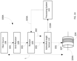
- Figure 1A illustrates a block diagram of one embodiment of a winding system 100A configured to control azimuthal alignment (with respect to an axis 102 parallel to a length L of unwound anti-resonant hollow core fiber 2 101) of a cross-section of the unwound anti-resonant hollow core fiber 101 when winding such unwound anti-resonant hollow core fiber 101 into a coil 104.
- Figure 1B illustrates a cross-section 100B of one embodiment of an anti-resonant hollow core fiber 101' comprises at least one set 101B of anti-resonant capillary elements (or capillaries) and a jacket 101A.
- Each set 101B of anti-resonant capillary elements comprises one or more capillary elements 101B-1, 101B-2; if a set 101B of anti-resonant capillary elements comprises two or more capillary elements 101B-1, 101B-2, each such capillary element is nested within another capillary element of the set 101B.
- the jacket 101A and each capillary element are hollow tubes, e.g., with a circular or non-circular cross-section; optionally, the jacket 101A and each capillary element is formed from glass.
- each set 101B of anti-resonant capillary elements is equidistantly spaced around an interior sidewall (or surface) 101A-1 of the jacket 101A; for pedagogical purposes, Figure 1B illustrates such a disposition.
- each set 101B of anti-resonant capillary elements is not equidistantly spaced around an interior sidewall 101A-1 of the jacket 101A.
- Each set 101B of anti-resonant capillary elements is affixed to an interior sidewall 101A-1 of the jacket 101A.
- each capillary element of each set 101B of capillary elements contacts (or is attached to) the interior sidewall 101A-1 of the jacket 101A.
- the axis 102 parallel to the length L of the unwound anti-resonant hollow core fiber 101 passes through a center 114 of the cross-section of the unwound anti-resonant hollow core fiber 101.
- the fiber transmission axis is an axis through an optical fiber along a length L of the optical fiber and, e.g., parallel to axis 102. 2
- Wound anti-resonant hollow core fiber means the fiber wound to form a coil.
- Unwound anti-resonant hollow core fiber means anti-resonant hollow core fiber which has not been wound into a coil.
- hollow core fiber 101 propagates along the center 114 of the cross-section through the unwound anti-resonant hollow core fiber 101.
- the unwound anti-resonant hollow core fiber 101 is configured to be wound in a coil 104, around a mandrel 107, relative to a bend plane 112 of the unwound anti-resonant hollow core fiber 101.
- the coil 104 includes a winding axis 104A around which the coil 104 is wound.
- the bend plane 112 is orthogonal both to the winding axis 104A and to the cross-section 100B of the unwound anti-resonant hollow core fiber 101.
- An azimuthal orientation (or azimuthal angle) 116 of the cross-section 100B with respect to the bend plane 112 may be fixed or varying with respect to the axis 102 parallel to the length L of the unwound anti-resonant hollow core fiber 101 as the unwound anti-resonant hollow core fiber 101 is wound into the coil 104.
- an intersection of the bend plane 112 with a region 118 of, e.g., a line in, the jacket 101A must be selected.
- Such a region 118 of the jacket 101A may be where one set of anti-resonant capillary elements contacts (or is attached to) the jacket 101A or a region between two sets of anti-resonant capillary elements.
- Figure 1B illustrates that the bend plane 112 intersects with a region 118 of the jacket 101A where the set of anti-resonant capillary elements contacts (or is attached to) the inner sidewall 101A-1 of the jacket 101A.
- Each cross-section 100B is perpendicular to the length L of the unwound anti-resonant hollow core fiber 101.
- the winding system 100A includes a source (or fiber source) 108 of the unwound anti-resonant hollow core fiber 101.
- the fiber source 108 is configured to dispense the unwound anti-resonant hollow core fiber 101 to be wound into a coil 104.
- the fiber source 108 may be a spool of wound anti-resonant hollow core fiber, a machine used to manufacture the unwound anti-resonant hollow core fiber 101, or any other source of the unwound anti-resonant hollow core fiber 101.
- the winding system 100A further includes a rotator 105 configured to rotate the azimuthal orientation 116, of the cross-section 100B of the unwound anti-resonant hollow core fiber 101, with respect to an axis 102 along a length L of an unwound anti-resonant hollow core fiber 101.
- the rotator 105 may be a twist gimbal or a pair of pinch rollers. When the twist gimbal is used as the rotator 105, then optionally the fiber source 108 is mounted on the twist gimbal.
- one or more springs may be used to generate a tight fit between the pair of pinch rollers.
- the rotator 105 may be rotated ( e.g., by an electric motor, a human being, or another means) by an azimuthal angle with respect to an axis 102 along a length L of the unwound anti-resonant hollow core fiber 101) of the unwound anti-resonant hollow core fiber 101.
- the winding system 100A optionally includes anti-rotator 109 configured to prevent azimuthal rotation (caused by the rotator 105) from being imparted to the unwound anti-resonant hollow core fiber 101 being dispensed from the fiber source 108.
- the anti-rotator 109 comprises a moveable portion and another portion (moveable or fixed). The two portions are compressed, e.g., by spring(s), against one another so that friction prevents imparting the azimuthal rotation to the unwound anti-resonant hollow core fiber 101 being dispensed from the fiber source 108.
- the anti-rotator 109 may be implemented with two pairs of pinch rollers, a pinch roller and a fixed or rotatable capstan shaft, or another type of mechanism which prevents such propagation of the azimuthal rotation to the unwound anti-resonant hollow core fiber 101 being dispensed from the fiber source 108.
- one or more springs may be used to generate a tight fit between the pair of pinch rollers, the pinch roller and a capstan shaft, etc. to prevent such propagation of azimuthal rotation.
- the winding system 100A further includes an azimuthal angle sensor 110 optically coupled to the unwound anti-resonant hollow core fiber 101.
- the azimuthal angle sensor 110 is configured to (a) project an optical signal on the unwound anti-resonant hollow core fiber 101, (b) measure power or energy levels, e.g., with respect to frequency spectrum, of portions, of the optical signal, reflected from and/or traversing the circumference of capillaries, and (c) transmit data 110A about such incident power or energy levels to a processing system 103.
- the azimuthal angle sensor 110 makes such measurements continuously as the unwound anti-resonant hollow core fiber 101 is wound into the coil 104.
- the azimuthal angle sensor 110 may precede or follow the rotator 105. For example, if a continuous rate of rotation of the cross-section 110B of the unwound anti-resonant hollow core fiber 101 is desired, then optionally the rotator 105 would follow the azimuthal angle sensor 110.
- the winding system 100A also includes the processing system (or processing circuitry) 103 configured to receive the data 110A about the power or energy levels (measured by the azimuthal angle sensor 110), and to determine an azimuthal orientation of the cross-section 110B of the unwound anti-resonant hollow core fiber 101 with respect to the azimuthal angle sensor 110.
- the processing system 103 is configured to receive (from another system or from user input) (a) an initial azimuthal orientation of the cross-section 110B of the unwound anti-resonant hollow core fiber 101 with respect to a bend plane 112 and/or (b) a desired rate of azimuthal rotation with respect to length L of the unwound anti-resonant hollow core fiber 101.
- the processing system 103 uses the data 110A received from the azimuthal angle sensor 110 (and optionally the initial azimuthal orientation of the cross-section 110B and/or the desired rate of azimuthal rotation with respect to length L of the unwound anti-resonant hollow core fiber 101), the processing system 103 generates azimuthal correction data 103A transmitted to the rotator 105.
- the rotator 105 is configured to use the azimuthal correction data 103A to rotate the azimuthal orientation of the cross-section 110B of the unwound anti-resonant hollow core fiber 101 relative to a bend plane 112 of the unwound anti-resonant hollow core fiber 101 as the coil 104 is wound.
- FIG. 2A illustrates a block diagram of one embodiment of the azimuthal angle sensor 220.
- the azimuthal angle sensor 220 includes at least one optical source and at least two optical detectors.
- each optical source emits a broadband spectrum, e.g., a white spectrum, near infrared spectrum, or a spectrum ranging from infrared to ultraviolet, or another spectrum.
- Each optical detector provides an electrical signal whose amplitude is proportional to an amount of incident optical energy.
- each optical detector includes a spectrometer (or an optical spectrum analyzer) configured to provide incident optical power with respect to frequency; however, each optical detector may be an alternative type of optical detector such as a Michelson interferometer.
- the illustrated azimuthal angle sensor 220 includes an optical source (or light source) 222 and two optical detectors 224A, 224B (i.e., a first optical detector (detector A) 224A and a second optical detector (detector B) 224B).
- Each optical detector is configured to collect scattered light and disposed at a different azimuthal angle with respect to an axis A parallel to an optical signal 225 (emitted from an optical (or light) source 222); this facilitates characterization of azimuthal orientation (of the cross-section 210B of the unwound anti-resonant hollow core fiber 201) with respect to the axis 102 along the length of the unwound anti-resonant hollow core fiber 201.
- a first azimuthal angle ⁇ A with respect to the axis A parallel to the optical signal 225 and the detector A 224A is, for example, 95 degrees
- the second azimuthal angle ⁇ B with respect to the axis A parallel to the optical signal 225 and the detector A 224B is 125 degrees
- An azimuthal offset angle ⁇ O is a magnitude of a difference between the first azimuthal angle O A and the second azimuthal angle ⁇ B .
- An azimuthal angular center 227 is midway between the two optical detectors 224A, 224B and is at a center azimuthal angle Oc, e.g., 15 degrees, which is one half of the sum of ⁇ A and ⁇ B and is one half of Oc.
- Oc center azimuthal angle
- the optical source 222 is configured to generate an optical signal 225 projected on an exterior surface (or sidewall) 2010 of the jacket 201A of the unwound anti-resonant hollow core fiber 201.
- the exterior surface 2010 is parallel to the length L of the unwound anti-resonant hollow core fiber 201.
- the azimuthal angle sensor 220 optionally includes an optical lens 226 configured to collimate the optical signal 225 so that more optical energy from the optical signal 225 is incident upon the jacket 201A of the unwound anti-resonant hollow core fiber 201.
- the bend plane 212 is illustrated bisecting one set of anti-resonant capillaries 201B.
- Figure 2B illustrates one embodiment of a diagram of a cross-section 210B of an unwound anti-resonant hollow core fiber 201 upon which an optical signal 225 is incident.
- Figure 2B illustrates the center 214 of the cross-section 210B of the unwound anti-resonant hollow core fiber 201.
- Figure 2B illustrates how portions 225A, 225B, 225C of the optical signal 225 are either reflected from and traverse around different capillaries of one set of anti-resonant capillaries 201B.
- other portions of the optical signal 225 would be reflected from and traverse around different capillaries of each set of anti-resonant capillaries of the unwound anti-resonant hollow core fiber 201.
- the unwound anti-resonant hollow core fiber 201 is illustrated with a set of anti-resonant capillaries 201B comprising three nested anti-resonant capillaries 201B-1, 201B-2, 201B-3.
- a first portion 225A of the optical signal 225 is reflected where the first capillary 201B-1 contacts or joins, e . g ., the inner surface 201A-1 of, the jacket 201A.
- a second portion 225B of the optical signal 225 traverses around a wall 229-2 of the second capillary 201B-2 before being received by the optical detector 224.
- a third portion 225C of the optical signal 225 traverses around a wall 229-3 of the third capillary 201B-3 before being received by the optical detector 224.
- the propagation distance of the first portion 225A is less than the propagation distance of the second portion 225B (because the second portion 225B traverses around the wall 229-2 of the second capillary 201B-2 and the first portion 225A does not traverse around a wall of a capillary).
- the propagation distance of the second portion 225B is less than the propagation distance of the third portion 225C because the circumference of the second capillary 201B-2 is less than the circumference of the third capillary 201B-3 travelled by the third portion 225C.
- the first portion 225A first arrives at the optical detector 224 at time T
- the second portion 225B first arrives at the optical detector 224 at time T + ⁇ 1
- the third portion 225C arrives at the optical detector 224 at time T + ⁇ 2 .
- ⁇ 1 is a difference in times between first arrival (at the optical detector 224) of the second portion 225B and the first portion 225A.
- ⁇ 2 is a difference in times of first arrival (at the optical detector 224) between third portion 225C and the first portion 225A.
- ⁇ 2 - ⁇ 1 is a difference in times of first arrival (at the optical detector 224) between the third portion 225C and the second portion 225B.
- Data 110A about the power or energy levels incident upon each optical detector 224A, 224B is electrically coupled to a processing system 103.
- Figure 3A illustrates a flow diagram of one embodiment of a method 330 of operation of a system for winding a coil of optical fiber.
- the optical fiber is anti-resonant hollow core optical fiber.
- method 330 may be implemented by the winding system 100A, the unwound anti-resonant hollow core fiber 101, and techniques described herein; however, embodiments of the invention may be applicable to other winding systems, other types of fiber, and/or other techniques.
- the winding system 100A is calibrated so that the at least two optical detectors 224A, 224B are aligned with respect to a set of capillaries or a space between two sets of capillaries.
- calibration entails azimuthally rotating a cross-section 110B until a set of capillaries or space is detected and aligning respectively the at least two optical detectors or the space so that respectively the set of capillaries or the space is centered, i . e ., that each of two optical detectors receives an equal amount of incident optical power within a temporal region representative of the set of capillaries.
- the temporal region representative of a set of capillaries means a region of energy or power whose temporal delay is equivalent to a physical dimension, e . g ., a circumference, of the set of capillaries; optionally, the physical dimension may be (a) a circumference of a largest or a smallest capillary of the set or (b) a difference in circumferences of two capillaries of the set.
- a desired azimuthal orientation of a cross-section 110B with respect to a bend plane 112, 212 and/or a desired rate of azimuthal rotation of the cross-section 110B with respect to length of the unwound anti-resonant hollow core fiber 101 is received, e .g., by the processing system 103.
- the initial azimuthal orientation with respect to a bend plane 112, 212 may have the bend plane 212 bisecting a cross-section of one set of anti-resonant capillaries 201B; alternatively, the initial azimuthal orientation can be anywhere between lines bisecting cross-sections of two adjacent sets of anti-resonant capillary elements.
- one or both of the aforementioned types of data may be previously stored, in the processing system 103, by a user or designer of the winding system 100A.
- an optical signal 225 is projected on an exterior surface 2010 of the jacket 201A of the unwound anti-resonant hollow core fiber 101.
- the exterior surface 2010 is parallel with the length L of the unwound anti-resonant hollow core fiber 101.
- block 330C optical signal projection on the unwound anti-resonant hollow core fiber 101 is performed additionally or alternatively prior to or as part of block 330A (calibration).
- power or energy levels e . g ., with respect to frequency spectrum, of portions, of the optical signal 225, reflected from and/or traversing around the circumference of at least one capillary of the unwound anti-resonant hollow core fiber 101 are measured, e . g ., with the azimuthal angle sensor 110.
- the azimuthal angle sensor 110 comprises at least two optical detectors 224A, 224B each of which detects such power or energy level incident on it; each pair of optical detectors 224A, 224B are separated by an offset azimuthal angle.
- data 110A about the measured power or energy levels is transmitted, e . g ., to and received by the processing system 103.
- Such azimuthal correction data is configured to be used to change or adjust an azimuthal alignment or orientation of the cross-section 110B with respect to the bend plane 112 .
- the azimuthal correction data may correspond to a change or adjustment to initially set a desired azimuthal alignment of the cross-section with respect to the bend plane, e.g., to correct for azimuthal rotation of the cross-section induced by the fiber source 108, and/or to affect the desired rate of azimuthal rotation of the cross-section 110B with respect to the length of the unwound anti-resonant hollow core fiber 101.
- azimuthal correction data 103A representing the change to the azimuthal alignment of the cross-section 110B with respect to the bend plane 112 is transmitted, e.g., from the processing system 103 to the rotator 105 which receives such azimuthal correction data 103A.
- the azimuthal alignment of the cross-section 110B or another cross-section with respect to the bend plane 112 is adjusted, e.g., by the rotator 105.
- such adjustment causes a continuous azimuthal rotation or a periodically varying azimuthal rotation of the cross-section of the unwound anti-resonant hollow core fiber 101.
- a coil is, e.g., partially, wound, e.g., on a mandrel 107.
- Figure 3B illustrates a flow diagram of one embodiment of a method 332 of determining a change or adjustment to an azimuthal alignment of the cross-section 110B with respect to the bend plane 112, e . g ., block 330E.
- block 330E may be implemented in other ways.
- method 332 may be implemented by the processing system 103; however, the method 332 may be implemented elsewhere, e . g ., in a cloud computing system remotely located from the winding system 100A.
- optical path delay regions of interest (in a time domain) for the unwound anti-resonant hollow core fiber 101 (being wound) are identified.
- an optical path delay region of interest is identified or determined for each of one or more capillary elements 101B-1, 101B-2 of a set of anti-resonant capillary elements 101B, e.g., each capillary element of the set.
- Figure 2B illustrates a first portion 225A of an optical signal reflected from the inner surface 201A-1 of the jacket 201A.
- Each optical path delay region of interest is around, e.g., centered around a relative time delay of optical signal travel through a circumference of one capillary element 101B-1, 101B-2.
- At least two sets of data is received, e . g ., from each of at least two optical detectors 224A, 224B of the azimuthal angle sensor 110.
- each set of data includes detected optical power, e.g., incident on a unique optical detector (for example, a unique spectrometer) with respect to wavelength ("wavelength domain data") or with respect to frequency (“frequency domain data”), e . g ., when each detector is a spectrometer.
- wavelength domain data is transformed to frequency domain data ("wavelength domain to frequency domain transformed data").
- wavelength domain to frequency domain transformed data may not be equally spaced in a frequency domain
- interpolation is optionally performed on the wavelength domain to frequency domain transformed data to obtain data including optical power incident on the spectrometer with respect to frequency and which is equally spaced in the frequency domain.
- This facilitates a more efficient performance of the inverse Fourier transform, e . g ., an inverse discrete Fourier transform.
- Equally spaced in frequency domain means that each optical power incident on the spectrometer is separated by another optical power incident on the spectrometer by a constant amount of frequency in the frequency domain.
- each of the optical detectors could be an interferometric detector, for example, a Michelson interferometer.
- each set of data would be detected optical power, e.g., incident on a unique optical detector, with respect to phase delay between two arms of the interferometric detector or mirror displacement in the interferometric detector ("interferometric path delay data").
- Interferometric path delay data Phase delay data or mirror displacement data with respect to detected optical power (determined by the interferometric detector) is conveyed to the processing system.
- each set of data including detected optical power with respect to frequency is transformed.
- Such transformation when the optical detectors are spectrometers may be, e.g., with an inverse Fourier transform (for example, an inverse discrete Fourier transform (DFT)) configured to transform each set of data including detected optical power with respect to frequency spectrum into a set of data including detected optical power with respect to time ("time domain data” or "optical path delay data”).
- DFT inverse discrete Fourier transform
- a maximum intensity, or a time delay at which the maximum intensity occurs, within a region of interest in a corresponding set of optical path delay data is identified.
- a gradient of the maximum intensities, or the time delays at which the maximum intensity occurs is determined.
- block 332E is implemented using each identified maximum intensity or time delay.
- azimuthal correction data configured to cause the gradient to be zero at an azimuthal angular center 227 between the two optical detectors 224A, 224B is determined.
- block 332F may be implemented by a proportional integral derivative (PID) controller, e.g., in the processing system 103.
- PID proportional integral derivative
- Methods of embodiments of the invention can be implemented in computer readable instructions, such as program modules or applications, which may be stored in the computer readable medium that is part of (optionally the memory circuitry) or communicatively coupled to the processing circuitry, and executed by the processing circuitry, optionally the processor circuitry.
- program modules or applications include routines, programs, objects, data components, data structures, algorithms, and the like, which perform particular tasks or implement particular abstract data types.
- Example 1 includes a method of operating a system for azimuthally aligning a hollow core optical fiber being wound around a winding axis into a coil, the method comprising: projecting an optical signal on an outer surface of a jacket of an unwound anti-resonant hollow core fiber; measuring, at each of two optical detectors, power or energy levels of portions, of the optical signal, reflected from and/or traversing around a circumference of at least one capillary of the unwound anti-resonant hollow core fiber, wherein the two optical detectors are separated from one another by an azimuthal offset angle with respect to a cross-section of the unwound anti-resonant hollow core fiber; receiving, from each optical detector, data about the measured power or energy levels; using (a) the data about the measured power or energy levels received from each optical detector and (b) at least one of (i) a desired azimuthal orientation of the cross-section with respect to a bend plane of the unwound anti-resonant hollow core fiber and (ii)
- Example 2 includes the method of Example 1, wherein adjusting the azimuthal alignment of the cross-section or another cross-section of the unwound anti-resonant hollow core fiber comprises diminishing azimuthal rotations of cross-sections of the unwound anti-resonant hollow core fiber.
- Example 3 includes the method of any of Examples 1-2, wherein adjusting the azimuthal alignment of the cross-section or the other cross-section comprises causing a continuous azimuthal rotation of the cross-section or the other cross-section of the unwound anti-resonant hollow core fiber or a periodically varying azimuthal rotation of the cross-section or the other cross-section of the unwound anti-resonant hollow core fiber.
- Example 4 includes the method of any of Examples 1-3, further comprising calibrating the system by azimuthally rotating the cross-section or the other cross-section of the unwound anti-resonant hollow core fiber until a set of capillaries or space between two sets of capillaries is detected and aligning respectively the two optical detectors or the space so that each of the two optical detectors receives an equal amount of incident optical power within a temporal region representative of the set of capillaries.
- Example 5 includes the method of any of Examples 1-4, further comprising receiving at least one of: the desired azimuthal orientation of the cross-section of the unwound anti-resonant hollow core fiber with respect to the bend plane and a desired rate of azimuthal rotation of the cross-section of the anti-resonant hollow core optical fiber with respect to the length of the unwound anti-resonant hollow core fiber.
- Example 6 includes the method of any of Examples 1-5, wherein the optical signal comprises white light, near infrared light, or a spectrum ranging from infrared light to ultraviolet light, or another optical spectrum.
- Example 7 includes the method of any of Examples 1-6, wherein measuring the power or energy levels comprises measuring the power or energy levels with respect to frequency spectrum.
- Example 8 includes the method of any of Examples 1-7, wherein determining the azimuthal correction data comprises: identifying optical path delay regions of interest in the unwound anti-resonant hollow core fiber; receiving at least two sets of data each of which includes detected optical power with respect to wavelength, frequency, or interferometric delay, wherein each pair of sets of data is received from each of the two optical detectors; transforming each set of data including detected optical power into a set of data including optical path delay data; and for each set of optical path delay data, identifying the maximum intensity, or the time delay at which the maximum intensity occurs, within an optical path delay region of interest in a corresponding set of optical path delay data is identified; determining a gradient of respectively maximum intensities or time delays; and determining azimuthal correction data configured to cause the gradient to be zero at an azimuthal angular center between the two optical detectors.
- Example 9 includes a program product comprising a non-transitory processor readable medium on which program instructions are embodied, wherein the program instructions are configured, when executed by at least one programmable processor, to cause the at least one programmable processor to execute a process to cause a hollow core optical fiber to be azimuthally aligned when being wound around a winding axis into a coil, the process comprising: receiving, from each of two optical detectors, data about power or energy levels measured at each of the two optical detectors, wherein the two optical detectors are separated from one another by an azimuthal offset angle with respect to a cross-section of an unwound anti-resonant hollow core fiber; using (a) the data about the measured power or energy levels received from each optical detector and (b) at least one of (i) a desired azimuthal orientation of a cross-section with respect to a bend plane of the unwound anti-resonant hollow core fiber and (ii) a desired rate of azimuthal rotation with respect to a length of the
- Example 10 includes the program product of Example 9, wherein the process further comprises causing azimuthal rotation of the cross-section or the other cross-section of the unwound anti-resonant hollow core fiber until a set of capillaries or space between two sets of capillaries is detected and alignment of respectively the two optical detectors or the space so that each of the two optical detectors receives an equal amount of incident optical power within a temporal region representative of the set of capillaries.
- Example 11 includes the program product of any of Examples 9-10, wherein the process further comprises receiving at least one of: the desired azimuthal orientation of the cross-section of the unwound anti-resonant hollow core fiber with respect to the bend plane and a desired rate of azimuthal rotation of the cross-section of the unwound anti-resonant hollow core fiber with respect to the length of the unwound anti-resonant hollow core fiber.
- Example 12 includes the program product of any of Examples 9-11, wherein the power or energy levels comprise power or energy levels with respect to frequency spectrum.
- Example 13 includes the program product of any of Examples 9-12 wherein determining the azimuthal correction data comprises: identifying optical path delay regions of interest in the unwound anti-resonant hollow core fiber; receiving two sets of data each of which includes detected optical power with respect to wavelength, frequency, or interferometric delay, wherein each pair of sets of data is received from the two optical detectors; transforming each set of data including detected optical power into a set of data including optical path delay data; and for each set of optical path delay data, identifying the maximum intensity, or the time delay at which the maximum intensity occurs, within an optical path delay region of interest in a corresponding set of optical path delay data is identified; determining a gradient of respectively maximum intensities or time delays; and determining azimuthal correction data configured to cause the gradient to be zero at an azimuthal angular center between the two optical detectors.
- Example 14 includes an apparatus for azimuthally aligning a cross-section of unwound anti-resonant hollow core fiber when winding such unwound anti-resonant hollow core fiber into a coil, the apparatus comprising: a source of the unwound anti-resonant hollow core fiber, wherein the unwound anti-resonant hollow core fiber comprises at least one set of anti-resonant capillary elements and a jacket, wherein the at least one set of anti-resonant capillary elements is affixed to an interior sidewall of the jacket; a sensor configured to determine an azimuthal rotation offset of the unwound anti-resonant hollow core fiber, wherein the sensor comprises at least one optical source and at least two optical detectors, wherein each optical source is configured to generate an optical signal, wherein each optical signal is configured to be incident on an exterior surface of a jacket of the unwound anti-resonant hollow core fiber, wherein each detector is separated from another detector by an azimuthal offset angle with respect to a cross-
- Example 15 includes the apparatus of Example 14, wherein azimuthally rotate the cross-section or the other cross-section comprises causing a continuous azimuthal rotation of the cross-section or the other cross-section of the unwound anti-resonant hollow core fiber or a periodically varying azimuthal rotation of the cross-section or the other cross-section of the unwound anti-resonant hollow core fiber.
- Example 16 includes the apparatus of any of Examples 14-15, wherein the processing circuitry is further configured to receive at least one of: the desired azimuthal orientation of the cross-section of the unwound anti-resonant hollow core fiber with respect to the bend plane and a desired rate of azimuthal rotation of the cross-section of the anti-resonant hollow core fiber with respect to the length of the unwound anti-resonant hollow core fiber.
- Example 17 includes the apparatus of any of Examples 14-16, wherein the optical signal comprises white light, near infrared light, or a spectrum ranging from infrared light to ultraviolet light, or another optical spectrum.
- Example 18 includes the apparatus of any of Examples 14-17, wherein measure the power or energy levels comprises measuring the power or energy levels with respect to frequency spectrum.
- Example 19 includes the apparatus of any of Examples 14-18, wherein determine the azimuthal correction data comprises: identify optical path delay regions of interest in the unwound anti-resonant hollow core fiber; receive two sets of data each of which includes detected optical power with respect to wavelength, frequency, or interferometric delay, wherein each pair of sets of data is received from the two optical detectors; transform each set of data including detected optical power into a set of data including optical path delay data; and for each set of optical path delay data, identify the maximum intensity, or the time delay at which the maximum intensity occurs, within an optical path delay region of interest in a corresponding set of optical path delay data is identified; determine a gradient of respectively maximum intensities or time delays; and determine azimuthal correction data configured to cause the gradient to be zero at an azimuthal angular center between two optical detectors.
- Example 20 includes the apparatus of any of Examples 14-19, wherein control the azimuthal rotation of the cross-section or another cross-section of the unwound anti-resonant hollow core fiber comprises diminishing azimuthal rotations of cross-sections of the unwound anti-resonant hollow core fiber.
Landscapes
- Physics & Mathematics (AREA)
- Optics & Photonics (AREA)
- General Physics & Mathematics (AREA)
- Chemical & Material Sciences (AREA)
- Analytical Chemistry (AREA)
- Light Guides In General And Applications Therefor (AREA)
Abstract
Techniques are provided for controlling azimuthal alignment of a cross-section of the anti-resonant hollow core fiber when winding such anti-resonant hollow core fiber into a coil.
Description
- This invention was made with Government support under Contract No. FA9453-20-C-0013 awarded by the Air Force Research Laboratory. The Government has certain rights in the invention.
- In comparison to solid core optical fibers, hollow core optical fibers (or hollow core fibers) may exhibit lower propagation loss and non-linearities. One type of hollow core fiber is an anti-resonant hollow core fiber. The anti-resonant hollow core fiber, including a nested anti-resonant hollow core fiber, has lower loss than other hollow fibers. Anti-resonant hollow core fibers are further described in Francesco Poletti, "Nested antiresonant nodeless hollow core fiber," Opt. Express 22, 23807-23828 (2014), which is incorporated by reference herein in its entirety. An unwound length of an optical fiber may be wound into a coil. A coil of optical fiber may be used in a sensor, e.g., an optical fiber gyroscope or a gas sensor, or for non-linear optic applications. A coil of appropriately designed anti-resonant hollow core fiber theoretically exhibits lower loss and non-linearities. Thus, for example, a measurement system implemented with the coil of anti-resonant hollow core fiber theoretically exhibits higher measurement sensitivity.
- However, when optical fiber is wound on a spool to be dispensed to form such a coil, an azimuthal angle of a cross-section of the optical fiber varies, e.g., randomly, as a length of the fiber is wound into the coil. Cross-sections of an anti-resonant hollow core fiber, and of microstructures comprising the fiber, typically have different azimuthal rotations with respect to one another. Such variation in azimuthal angle of such cross-sections undesirably results in higher propagation loss in the coil formed from anti-resonant hollow core fiber.
- A method of operating a system is provided for azimuthally aligning a hollow core optical fiber being wound around a winding axis into a coil. The method comprises: projecting an optical signal on an outer surface of a jacket of an unwound anti-resonant hollow core fiber; measuring, at each of two optical detectors, power or energy levels of portions, of the optical signal, reflected from and/or traversing around a circumference of at least one capillary of the unwound anti-resonant hollow core fiber, wherein the two optical detectors are separated from one another by an azimuthal offset angle with respect to a cross-section of the unwound anti-resonant hollow core fiber; receiving, from each optical detector, data about the measured power or energy levels; using (a) the data about the measured power or energy levels received from each optical detector and (b) at least one of (i) a desired azimuthal orientation of the cross-section with respect to a bend plane of the unwound anti-resonant hollow core fiber and (ii) a desired rate of azimuthal rotation with respect to a length of the unwound anti-resonant hollow core fiber, (x) identifying, for each of such data received from an optical detector, a maximum intensity with respect to optical path delay or a time delay at which the maximum intensity occurs with respect to the optical path delay and then using each maximum intensity or time delay, (y) determining azimuthal correction data, wherein the cross-section is perpendicular to a length of the unwound anti-resonant hollow core fiber, wherein the bend plane is orthogonal both to the winding axis and to the cross-section of the unwound anti-resonant hollow core fiber; using the azimuthal correction data, adjusting an azimuthal alignment of the cross-section or another cross-section of the unwound anti-resonant hollow core fiber with respect to the bend plane; and winding the coil of the optical fiber using the unwound anti-resonant hollow core fiber whose azimuthal alignment has been adjusted.
- A program product is provided and comprises a non-transitory processor readable medium on which program instructions are embodied, wherein the program instructions are configured, when executed by at least one programmable processor, to cause the at least one programmable processor to execute a process to cause a hollow core optical fiber to be azimuthally aligned when being wound around a winding axis into a coil. The process comprises: receiving, from each of two optical detectors, data about power or energy levels measured at each of the two optical detectors, wherein the two optical detectors are separated from one another by an azimuthal offset angle with respect to a cross-section of an unwound anti-resonant hollow core fiber; using (a) the data about the measured power or energy levels received from each optical detector and (b) at least one of (i) a desired azimuthal orientation of a cross-section with respect to a bend plane of the unwound anti-resonant hollow core fiber and (ii) a desired rate of azimuthal rotation with respect to a length of the unwound anti-resonant hollow core fiber, (x) identifying, for each of such data received from an optical detector, a maximum intensity with respect to optical path delay or a time delay at which the maximum intensity occurs with respect to the optical path delay and then using each maximum intensity or time delay, (y) determining azimuthal correction data, wherein the cross-section is perpendicular to a length of the unwound anti-resonant hollow core fiber, wherein the bend plane is orthogonal both to the winding axis and to the cross-section of the unwound anti-resonant hollow core fiber; and transmitting the azimuthal correction data which is configured to be used to adjust an azimuthal alignment of the cross-section or another cross-section of the unwound anti-resonant hollow core fiber with respect to the bend plane as a coil of optical fiber is wound using the unwound anti-resonant hollow core fiber whose azimuthal alignment has been adjusted.
- An apparatus is provided and is configure to azimuthally align a cross-section of unwound anti-resonant hollow core fiber when winding such unwound anti-resonant hollow core fiber into a coil. The apparatus comprises: a source of the unwound anti-resonant hollow core fiber, wherein the unwound anti-resonant hollow core fiber comprises at least one set of anti-resonant capillary elements and a j acket, wherein the at least one set of anti-resonant capillary elements is affixed to an interior sidewall of the jacket; a sensor configured to determine an azimuthal rotation offset of the unwound anti-resonant hollow core fiber, wherein the sensor comprises at least one optical source and at least two optical detectors, wherein each optical source is configured to generate an optical signal, wherein each optical signal is configured to be incident on an exterior surface of a jacket of the unwound anti-resonant hollow core fiber, wherein each detector is separated from another detector by an azimuthal offset angle with respect to a cross-section of the unwound anti-resonant hollow core fiber, wherein the cross-section is perpendicular to a length of the unwound anti-resonant hollow core fiber, wherein each detector is configured to measure power or energy levels of portions, of the optical signal, reflected from and/or traversing around a circumference of at least one capillary of the unwound anti-resonant hollow core fiber; processing circuitry communicatively coupled to the sensor and configured to receive data about the power or the energy levels measured by each detector; wherein the processing circuitry is further configured to use (a) the data about the measured power or energy levels received from each optical detector and (b) at least one of (i) a desired azimuthal orientation of a cross-section with respect to a bend plane of the unwound anti-resonant hollow core fiber and (ii) a desired rate of azimuthal rotation with respect to a length of the unwound anti-resonant hollow core fiber, (x) identify, for each of such data received from an optical detector, a maximum intensity with respect to optical path delay or a time delay at which the maximum intensity occurs with respect to the optical path delay and then using each maximum intensity or time delay, (y) determine azimuthal correction data, wherein the cross-section is perpendicular to a length of the unwound anti-resonant hollow core fiber; a mandrel comprising a winding axis and configured to wind, into the coil, the unwound anti-resonant hollow core fiber dispensed from the source of the unwound anti-resonant hollow core fiber; and a rotation mechanism comprising a motor and configured, responsive to the azimuthal correction data, to azimuthally rotate the cross-section or another cross-section of the unwound anti-resonant hollow core fiber to control azimuthal rotation of the unwound anti-resonant hollow core fiber, relative to a bend plane of the unwound anti-resonant hollow core fiber, as the coil is wound on the mandrel, wherein the bend plane is orthogonal to the cross-section of the unwound anti-resonant hollow core fiber and is orthogonal to the winding axis of the mandrel.
- Understanding that the drawings depict only exemplary embodiments and are not therefore to be considered limiting in scope, the exemplary embodiments will be described with additional specificity and detail through the use of the accompanying drawings, in which:
-
Figure 1A illustrates a block diagram of one embodiment of a winding system configured to control azimuthal alignment (with respect to an axis parallel to a length of an anti-resonant hollow core fiber) of a cross-section of the anti-resonant hollow core fiber when winding such anti-resonant hollow core fiber into a coil; -
Figure 1B illustrates a cross-section of one embodiment of an anti-resonant hollow core fiber comprises at least one set of anti-resonant capillary elements and a jacket; -
Figure 2A illustrates a block diagram of one embodiment of the azimuthal angle sensor; -
Figure 2B illustrates one embodiment of a diagram of a cross section of an unwound anti-resonant hollow core fiber upon which an optical signal is incident; -
Figure 3A illustrates a flow diagram of one embodiment of a method of operation of a system for winding a coil of optical fiber; and -
Figure 3B illustrates a flow diagram of one embodiment of a method of determining a change or adjustment to an azimuthal alignment of the cross-section with respect to the bend plane. - In accordance with common practice, the various described features are not drawn to scale but are drawn to emphasize specific features relevant to the exemplary embodiments. Reference characters denote like elements throughout figures and text.
- In the following detailed description, reference is made to the accompanying drawings that form a part hereof, and in which is shown by way of illustration specific illustrative embodiments. However, it is to be understood that other embodiments may be utilized and that structural, mechanical, and electrical changes may be made. Furthermore, the method presented in the drawing figures and the specification is not to be construed as limiting the order in which the individual steps may be performed. The following detailed description is, therefore, not to be taken in a limiting sense.
- For pedagogical purposes, embodiments of the invention are illustrated with respect to anti-resonant hollow core fiber. However, embodiments of the invention are more generally applicable to other types of hollow core optical fibers.
- Techniques are provided for controlling azimuthal alignment (with respect to an axis along a length of an anti-resonant hollow core fiber) of a cross-section of the anti-resonant hollow core fiber when winding such anti-resonant hollow core fiber into a coil. Optionally, such techniques may be used to substantially diminish differences between azimuthal rotations of cross-sections of the anti-resonant hollow core fiber, about a fiber transmission axis1, in parallel planes. Optionally and alternatively, such techniques can be used to induce a predetermined rate of azimuthal rotation of the anti-resonant hollow core fiber when the anti-resonant hollow core fiber is wound as a coil; optionally, this may be done to diminish polarization mode dispersion or to introduce circular polarization in lieu of linear polarization. The predetermined rate of azimuthal rotation may be a constant amount, e.g., zero, or a variable one, e.g., a continuously varying rotation rate, for example that is sinusoidally varying.
-
Figure 1A illustrates a block diagram of one embodiment of awinding system 100A configured to control azimuthal alignment (with respect to anaxis 102 parallel to a length L of unwound anti-resonant hollow core fiber2 101) of a cross-section of the unwound anti-resonanthollow core fiber 101 when winding such unwound anti-resonanthollow core fiber 101 into acoil 104.Figure 1B illustrates across-section 100B of one embodiment of an anti-resonant hollow core fiber 101' comprises at least oneset 101B of anti-resonant capillary elements (or capillaries) and ajacket 101A. Eachset 101B of anti-resonant capillary elements comprises one or morecapillary elements 101B-1, 101B-2; if aset 101B of anti-resonant capillary elements comprises two or morecapillary elements 101B-1, 101B-2, each such capillary element is nested within another capillary element of theset 101B. Thejacket 101A and each capillary element are hollow tubes, e.g., with a circular or non-circular cross-section; optionally, thejacket 101A and each capillary element is formed from glass. - Optionally, each
set 101B of anti-resonant capillary elements is equidistantly spaced around an interior sidewall (or surface) 101A-1 of thejacket 101A; for pedagogical purposes,Figure 1B illustrates such a disposition. However, in other embodiments, each set 101B of anti-resonant capillary elements is not equidistantly spaced around aninterior sidewall 101A-1 of thejacket 101A. Eachset 101B of anti-resonant capillary elements is affixed to aninterior sidewall 101A-1 of thejacket 101A. Optionally, each capillary element of eachset 101B of capillary elements contacts (or is attached to) theinterior sidewall 101A-1 of thejacket 101A. Optionally, theaxis 102 parallel to the length L of the unwound anti-resonanthollow core fiber 101 passes through acenter 114 of the cross-section of the unwound anti-resonanthollow core fiber 101. Optionally, the length L of the unwound anti-resonant
1 The fiber transmission axis is an axis through an optical fiber along a length L of the optical fiber and, e.g., parallel toaxis 102.
2 Wound anti-resonant hollow core fiber means the fiber wound to form a coil. Unwound anti-resonant hollow core fiber means anti-resonant hollow core fiber which has not been wound into a coil.hollow core fiber 101 propagates along thecenter 114 of the cross-section through the unwound anti-resonanthollow core fiber 101. - The unwound anti-resonant
hollow core fiber 101 is configured to be wound in acoil 104, around amandrel 107, relative to abend plane 112 of the unwound anti-resonanthollow core fiber 101. Thecoil 104 includes awinding axis 104A around which thecoil 104 is wound. Thebend plane 112 is orthogonal both to thewinding axis 104A and to thecross-section 100B of the unwound anti-resonanthollow core fiber 101. - An azimuthal orientation (or azimuthal angle) 116 of the
cross-section 100B with respect to thebend plane 112 may be fixed or varying with respect to theaxis 102 parallel to the length L of the unwound anti-resonanthollow core fiber 101 as the unwound anti-resonanthollow core fiber 101 is wound into thecoil 104. Optionally, if theazimuthal orientation 116 of thecross-section 100B with respect to thebend plane 112 is fixed, then an intersection of thebend plane 112 with aregion 118 of, e.g., a line in, thejacket 101A must be selected. Such aregion 118 of thejacket 101A may be where one set of anti-resonant capillary elements contacts (or is attached to) thejacket 101A or a region between two sets of anti-resonant capillary elements. For pedagogical reasons,Figure 1B illustrates that thebend plane 112 intersects with aregion 118 of thejacket 101A where the set of anti-resonant capillary elements contacts (or is attached to) theinner sidewall 101A-1 of thejacket 101A. Eachcross-section 100B is perpendicular to the length L of the unwound anti-resonanthollow core fiber 101. - Returning to
Figure 1A , the windingsystem 100A includes a source (or fiber source) 108 of the unwound anti-resonanthollow core fiber 101. Thefiber source 108 is configured to dispense the unwound anti-resonanthollow core fiber 101 to be wound into acoil 104. Optionally, thefiber source 108 may be a spool of wound anti-resonant hollow core fiber, a machine used to manufacture the unwound anti-resonanthollow core fiber 101, or any other source of the unwound anti-resonanthollow core fiber 101. - The winding
system 100A further includes arotator 105 configured to rotate theazimuthal orientation 116, of thecross-section 100B of the unwound anti-resonanthollow core fiber 101, with respect to anaxis 102 along a length L of an unwound anti-resonanthollow core fiber 101. Optionally, therotator 105 may be a twist gimbal or a pair of pinch rollers. When the twist gimbal is used as therotator 105, then optionally thefiber source 108 is mounted on the twist gimbal. Optionally, when the pair of pinch rollers are used as therotator 105, one or more springs may be used to generate a tight fit between the pair of pinch rollers. Therotator 105 may be rotated (e.g., by an electric motor, a human being, or another means) by an azimuthal angle with respect to anaxis 102 along a length L of the unwound anti-resonant hollow core fiber 101) of the unwound anti-resonanthollow core fiber 101. - The winding
system 100A optionally includes anti-rotator 109 configured to prevent azimuthal rotation (caused by the rotator 105) from being imparted to the unwound anti-resonanthollow core fiber 101 being dispensed from thefiber source 108. The anti-rotator 109 comprises a moveable portion and another portion (moveable or fixed). The two portions are compressed, e.g., by spring(s), against one another so that friction prevents imparting the azimuthal rotation to the unwound anti-resonanthollow core fiber 101 being dispensed from thefiber source 108. Optionally, the anti-rotator 109 may be implemented with two pairs of pinch rollers, a pinch roller and a fixed or rotatable capstan shaft, or another type of mechanism which prevents such propagation of the azimuthal rotation to the unwound anti-resonanthollow core fiber 101 being dispensed from thefiber source 108. Optionally, for each such mechanism, one or more springs may be used to generate a tight fit between the pair of pinch rollers, the pinch roller and a capstan shaft, etc. to prevent such propagation of azimuthal rotation. - The winding
system 100A further includes anazimuthal angle sensor 110 optically coupled to the unwound anti-resonanthollow core fiber 101. Theazimuthal angle sensor 110 is configured to (a) project an optical signal on the unwound anti-resonanthollow core fiber 101, (b) measure power or energy levels, e.g., with respect to frequency spectrum, of portions, of the optical signal, reflected from and/or traversing the circumference of capillaries, and (c) transmitdata 110A about such incident power or energy levels to aprocessing system 103. Optionally, theazimuthal angle sensor 110 makes such measurements continuously as the unwound anti-resonanthollow core fiber 101 is wound into thecoil 104. - The
azimuthal angle sensor 110 may precede or follow therotator 105. For example, if a continuous rate of rotation of thecross-section 110B of the unwound anti-resonanthollow core fiber 101 is desired, then optionally therotator 105 would follow theazimuthal angle sensor 110. - The winding
system 100A also includes the processing system (or processing circuitry) 103 configured to receive thedata 110A about the power or energy levels (measured by the azimuthal angle sensor 110), and to determine an azimuthal orientation of thecross-section 110B of the unwound anti-resonanthollow core fiber 101 with respect to theazimuthal angle sensor 110. Optionally, theprocessing system 103 is configured to receive (from another system or from user input) (a) an initial azimuthal orientation of thecross-section 110B of the unwound anti-resonanthollow core fiber 101 with respect to abend plane 112 and/or (b) a desired rate of azimuthal rotation with respect to length L of the unwound anti-resonanthollow core fiber 101. Using thedata 110A received from the azimuthal angle sensor 110 (and optionally the initial azimuthal orientation of thecross-section 110B and/or the desired rate of azimuthal rotation with respect to length L of the unwound anti-resonant hollow core fiber 101), theprocessing system 103 generatesazimuthal correction data 103A transmitted to therotator 105. Therotator 105 is configured to use theazimuthal correction data 103A to rotate the azimuthal orientation of thecross-section 110B of the unwound anti-resonanthollow core fiber 101 relative to abend plane 112 of the unwound anti-resonanthollow core fiber 101 as thecoil 104 is wound. -
Figure 2A illustrates a block diagram of one embodiment of theazimuthal angle sensor 220. Theazimuthal angle sensor 220 includes at least one optical source and at least two optical detectors. Optionally, each optical source emits a broadband spectrum, e.g., a white spectrum, near infrared spectrum, or a spectrum ranging from infrared to ultraviolet, or another spectrum. Each optical detector provides an electrical signal whose amplitude is proportional to an amount of incident optical energy. Optionally, each optical detector includes a spectrometer (or an optical spectrum analyzer) configured to provide incident optical power with respect to frequency; however, each optical detector may be an alternative type of optical detector such as a Michelson interferometer. - For pedagogical purposes, the illustrated
azimuthal angle sensor 220 includes an optical source (or light source) 222 and twooptical detectors cross-section 210B of the unwound anti-resonant hollow core fiber 201) with respect to theaxis 102 along the length of the unwound anti-resonanthollow core fiber 201. In the embodiment illustrated inFigure 2A , a first azimuthal angle ΘA with respect to the axis A parallel to theoptical signal 225 and thedetector A 224A is, for example, 95 degrees, and the second azimuthal angle ΘB with respect to the axis A parallel to theoptical signal 225 and thedetector A 224B is 125 degrees. An azimuthal offset angle ΘO is a magnitude of a difference between the first azimuthal angle OA and the second azimuthal angle ΘB. An azimuthalangular center 227 is midway between the twooptical detectors - The
optical source 222 is configured to generate anoptical signal 225 projected on an exterior surface (or sidewall) 2010 of thejacket 201A of the unwound anti-resonanthollow core fiber 201. Theexterior surface 2010 is parallel to the length L of the unwound anti-resonanthollow core fiber 201. Theazimuthal angle sensor 220 optionally includes anoptical lens 226 configured to collimate theoptical signal 225 so that more optical energy from theoptical signal 225 is incident upon thejacket 201A of the unwound anti-resonanthollow core fiber 201. For pedagogical purposes, thebend plane 212 is illustrated bisecting one set ofanti-resonant capillaries 201B. -
Figure 2B illustrates one embodiment of a diagram of across-section 210B of an unwound anti-resonanthollow core fiber 201 upon which anoptical signal 225 is incident.Figure 2B illustrates thecenter 214 of thecross-section 210B of the unwound anti-resonanthollow core fiber 201. - For pedagogical purposes,
Figure 2B illustrates howportions optical signal 225 are either reflected from and traverse around different capillaries of one set ofanti-resonant capillaries 201B. In practice, other portions of theoptical signal 225 would be reflected from and traverse around different capillaries of each set of anti-resonant capillaries of the unwound anti-resonanthollow core fiber 201. For pedagogical purposes, the unwound anti-resonanthollow core fiber 201 is illustrated with a set ofanti-resonant capillaries 201B comprising three nestedanti-resonant capillaries 201B-1, 201B-2, 201B-3. Before being received by anoptical detector 224, afirst portion 225A of theoptical signal 225 is reflected where the first capillary 201B-1 contacts or joins, e.g., theinner surface 201A-1 of, thejacket 201A. Asecond portion 225B of theoptical signal 225 traverses around a wall 229-2 of the second capillary 201B-2 before being received by theoptical detector 224. A third portion 225C of theoptical signal 225 traverses around a wall 229-3 of the third capillary 201B-3 before being received by theoptical detector 224. The propagation distance of thefirst portion 225A is less than the propagation distance of thesecond portion 225B (because thesecond portion 225B traverses around the wall 229-2 of the second capillary 201B-2 and thefirst portion 225A does not traverse around a wall of a capillary). The propagation distance of thesecond portion 225B is less than the propagation distance of the third portion 225C because the circumference of the second capillary 201B-2 is less than the circumference of the third capillary 201B-3 travelled by the third portion 225C. Thus, thefirst portion 225A first arrives at theoptical detector 224 at time T, thesecond portion 225B first arrives at theoptical detector 224 at time T + τ1, and the third portion 225C arrives at theoptical detector 224 at time T + τ2. τ1 is a difference in times between first arrival (at the optical detector 224) of thesecond portion 225B and thefirst portion 225A. τ2 is a difference in times of first arrival (at the optical detector 224) between third portion 225C and thefirst portion 225A. τ2 - τ1 is a difference in times of first arrival (at the optical detector 224) between the third portion 225C and thesecond portion 225B.Data 110A about the power or energy levels incident upon eachoptical detector processing system 103. -
Figure 3A illustrates a flow diagram of one embodiment of amethod 330 of operation of a system for winding a coil of optical fiber. Optionally, the optical fiber is anti-resonant hollow core optical fiber. To the extent that the methods shown in any Figures are described herein as being implemented with any of the techniques illustrated herein, it is to be understood that other embodiments can be implemented in other ways. Optionally,method 330 may be implemented by the windingsystem 100A, the unwound anti-resonanthollow core fiber 101, and techniques described herein; however, embodiments of the invention may be applicable to other winding systems, other types of fiber, and/or other techniques. The blocks of the flow diagrams have been arranged in a generally sequential manner for ease of explanation; however, it is to be understood that this arrangement is merely exemplary, and it should be recognized that the processing associated with the methods (and the blocks shown in the Figures) can occur in a different order (for example, where at least some of the processing associated with the blocks is performed in parallel and/or in an event-driven manner). - Optionally, in
block 330A, the windingsystem 100A is calibrated so that the at least twooptical detectors cross-section 110B until a set of capillaries or space is detected and aligning respectively the at least two optical detectors or the space so that respectively the set of capillaries or the space is centered, i.e., that each of two optical detectors receives an equal amount of incident optical power within a temporal region representative of the set of capillaries. The temporal region representative of a set of capillaries means a region of energy or power whose temporal delay is equivalent to a physical dimension, e.g., a circumference, of the set of capillaries; optionally, the physical dimension may be (a) a circumference of a largest or a smallest capillary of the set or (b) a difference in circumferences of two capillaries of the set. Optionally, inblock 330B, a desired azimuthal orientation of across-section 110B with respect to abend plane cross-section 110B with respect to length of the unwound anti-resonanthollow core fiber 101 is received, e.g., by theprocessing system 103. Optionally, the initial azimuthal orientation with respect to abend plane bend plane 212 bisecting a cross-section of one set ofanti-resonant capillaries 201B; alternatively, the initial azimuthal orientation can be anywhere between lines bisecting cross-sections of two adjacent sets of anti-resonant capillary elements. Alternatively, one or both of the aforementioned types of data may be previously stored, in theprocessing system 103, by a user or designer of the windingsystem 100A. - In
block 330C, anoptical signal 225 is projected on anexterior surface 2010 of thejacket 201A of the unwound anti-resonanthollow core fiber 101. Theexterior surface 2010 is parallel with the length L of the unwound anti-resonanthollow core fiber 101. Optionally, block 330C (optical signal projection on the unwound anti-resonanthollow core fiber 101 is performed additionally or alternatively prior to or as part ofblock 330A (calibration). - In
block 330D, power or energy levels, e.g., with respect to frequency spectrum, of portions, of theoptical signal 225, reflected from and/or traversing around the circumference of at least one capillary of the unwound anti-resonanthollow core fiber 101 are measured, e.g., with theazimuthal angle sensor 110. Optionally, theazimuthal angle sensor 110 comprises at least twooptical detectors optical detectors optional block 330E,data 110A about the measured power or energy levels is transmitted, e.g., to and received by theprocessing system 103. - In
block 330F, using (a) thedata 110A about the measured power or energy levels and (b) at least one of (i) the desired azimuthal orientation of the cross section with respect to the bend plane and (ii) the desired rate of azimuthal rotation with respect to the length of the unwound anti-resonanthollow core fiber 101, (x) identifying, for each of such data received from an optical detector, a maximum intensity with respect to optical path delay or a time delay at which the maximum intensity occurs with respect to the optical path delay and then using each maximum intensity or time delay, (y) determining azimuthal correction data. Optionally, the identifying and determining are performed using theprocessing system 103. The cross-section is perpendicular to a length of the unwound anti-resonant hollow core fiber. - Such azimuthal correction data is configured to be used to change or adjust an azimuthal alignment or orientation of the
cross-section 110B with respect to thebend plane 112 . Optionally, the azimuthal correction data may correspond to a change or adjustment to initially set a desired azimuthal alignment of the cross-section with respect to the bend plane, e.g., to correct for azimuthal rotation of the cross-section induced by thefiber source 108, and/or to affect the desired rate of azimuthal rotation of thecross-section 110B with respect to the length of the unwound anti-resonanthollow core fiber 101. Inoptional block 330G,azimuthal correction data 103A representing the change to the azimuthal alignment of thecross-section 110B with respect to thebend plane 112 is transmitted, e.g., from theprocessing system 103 to therotator 105 which receives suchazimuthal correction data 103A. - In
block 330H, using theazimuthal correction data 103A, the azimuthal alignment of thecross-section 110B or another cross-section with respect to thebend plane 112 is adjusted, e.g., by therotator 105. Optionally, such adjustment causes a continuous azimuthal rotation or a periodically varying azimuthal rotation of the cross-section of the unwound anti-resonanthollow core fiber 101. Inblock 3301, a coil is, e.g., partially, wound, e.g., on amandrel 107. -
Figure 3B illustrates a flow diagram of one embodiment of amethod 332 of determining a change or adjustment to an azimuthal alignment of thecross-section 110B with respect to thebend plane 112, e.g., block 330E. However, block 330E may be implemented in other ways. To the extent that the methods shown in any Figures are described herein as being implemented with any of the techniques illustrated herein, it is to be understood that other embodiments can be implemented in other ways. Optionally,method 332 may be implemented by theprocessing system 103; however, themethod 332 may be implemented elsewhere, e.g., in a cloud computing system remotely located from the windingsystem 100A. The blocks of the flow diagrams have been arranged in a generally sequential manner for ease of explanation; however, it is to be understood that this arrangement is merely exemplary, and it should be recognized that the processing associated with the methods (and the blocks shown in the Figures) can occur in a different order (for example, where at least some of the processing associated with the blocks is performed in parallel and/or in an event-driven manner). - In
block 332A, optical path delay regions of interest (in a time domain) for the unwound anti-resonant hollow core fiber 101 (being wound) are identified. Optionally, an optical path delay region of interest is identified or determined for each of one or morecapillary elements 101B-1, 101B-2 of a set of anti-resonantcapillary elements 101B, e.g., each capillary element of the set. Based on a known diameter of eachcapillary element 101B-1, 101B-2 of a set of anti-resonantcapillary elements 101B, and a known optical group velocity of an optical signal traveling around each circumference of at least one, e.g., each,capillary element 101B-1, 101B-2, a relative time delay of the optical signal travel around each circumference of at least one, e.g., each,capillary element 101B-1, 101B-2, with respect to optical signal travel reflected from a portion of the hollow core fiber, e.g., aninner surface 201A-1 of thejacket 201A of the unwound anti-resonanthollow core fiber 101, is determined.Figure 2B illustrates afirst portion 225A of an optical signal reflected from theinner surface 201A-1 of thejacket 201A. Each optical path delay region of interest is around, e.g., centered around a relative time delay of optical signal travel through a circumference of onecapillary element 101B-1, 101B-2. - In
block 332B, at least two sets of data is received, e.g., from each of at least twooptical detectors azimuthal angle sensor 110. Such each set of data includes detected optical power, e.g., incident on a unique optical detector (for example, a unique spectrometer) with respect to wavelength ("wavelength domain data") or with respect to frequency ("frequency domain data"), e.g., when each detector is a spectrometer. When a set of data includes wavelength domain data, then the wavelength domain data is transformed to frequency domain data ("wavelength domain to frequency domain transformed data"). Because a separation between elements of wavelength domain to frequency domain transformed data may not be equally spaced in a frequency domain, interpolation is optionally performed on the wavelength domain to frequency domain transformed data to obtain data including optical power incident on the spectrometer with respect to frequency and which is equally spaced in the frequency domain. This facilitates a more efficient performance of the inverse Fourier transform, e.g., an inverse discrete Fourier transform. Equally spaced in frequency domain means that each optical power incident on the spectrometer is separated by another optical power incident on the spectrometer by a constant amount of frequency in the frequency domain. - Alternatively, each of the optical detectors could be an interferometric detector, for example, a Michelson interferometer. In such a case, each set of data would be detected optical power, e.g., incident on a unique optical detector, with respect to phase delay between two arms of the interferometric detector or mirror displacement in the interferometric detector ("interferometric path delay data"). Phase delay data or mirror displacement data with respect to detected optical power (determined by the interferometric detector) is conveyed to the processing system.
- In
block 332C, each set of data including detected optical power with respect to frequency is transformed. Such transformation, when the optical detectors are spectrometers may be, e.g., with an inverse Fourier transform (for example, an inverse discrete Fourier transform (DFT)) configured to transform each set of data including detected optical power with respect to frequency spectrum into a set of data including detected optical power with respect to time ("time domain data" or "optical path delay data"). If each set of data is "interferometric path delay data", then such set of data is transformed to optical power with respect to time by converting phase delay or mirror displacement to an equivalent time delay. - In
block 332D, for each set of optical path delay data, a maximum intensity, or a time delay at which the maximum intensity occurs, within a region of interest in a corresponding set of optical path delay data is identified. Inblock 332E, a gradient of the maximum intensities, or the time delays at which the maximum intensity occurs, is determined. Optionally, block 332E is implemented using each identified maximum intensity or time delay. Inblock 332F, azimuthal correction data configured to cause the gradient to be zero at an azimuthalangular center 227 between the twooptical detectors processing system 103. - Methods of embodiments of the invention can be implemented in computer readable instructions, such as program modules or applications, which may be stored in the computer readable medium that is part of (optionally the memory circuitry) or communicatively coupled to the processing circuitry, and executed by the processing circuitry, optionally the processor circuitry. Generally, program modules or applications include routines, programs, objects, data components, data structures, algorithms, and the like, which perform particular tasks or implement particular abstract data types.
- Example 1 includes a method of operating a system for azimuthally aligning a hollow core optical fiber being wound around a winding axis into a coil, the method comprising: projecting an optical signal on an outer surface of a jacket of an unwound anti-resonant hollow core fiber; measuring, at each of two optical detectors, power or energy levels of portions, of the optical signal, reflected from and/or traversing around a circumference of at least one capillary of the unwound anti-resonant hollow core fiber, wherein the two optical detectors are separated from one another by an azimuthal offset angle with respect to a cross-section of the unwound anti-resonant hollow core fiber; receiving, from each optical detector, data about the measured power or energy levels; using (a) the data about the measured power or energy levels received from each optical detector and (b) at least one of (i) a desired azimuthal orientation of the cross-section with respect to a bend plane of the unwound anti-resonant hollow core fiber and (ii) a desired rate of azimuthal rotation with respect to a length of the unwound anti-resonant hollow core fiber, (x) identifying, for each of such data received from an optical detector, a maximum intensity with respect to optical path delay or a time delay at which the maximum intensity occurs with respect to the optical path delay and then using each maximum intensity or time delay, (y) determining azimuthal correction data, wherein the cross-section is perpendicular to a length of the unwound anti-resonant hollow core fiber, wherein the bend plane is orthogonal both to the winding axis and to the cross-section of the unwound anti-resonant hollow core fiber; using the azimuthal correction data, adjusting an azimuthal alignment of the cross-section or another cross-section of the unwound anti-resonant hollow core fiber with respect to the bend plane; and winding the coil of the optical fiber using the unwound anti-resonant hollow core fiber whose azimuthal alignment has been adjusted.
- Example 2 includes the method of Example 1, wherein adjusting the azimuthal alignment of the cross-section or another cross-section of the unwound anti-resonant hollow core fiber comprises diminishing azimuthal rotations of cross-sections of the unwound anti-resonant hollow core fiber.
- Example 3 includes the method of any of Examples 1-2, wherein adjusting the azimuthal alignment of the cross-section or the other cross-section comprises causing a continuous azimuthal rotation of the cross-section or the other cross-section of the unwound anti-resonant hollow core fiber or a periodically varying azimuthal rotation of the cross-section or the other cross-section of the unwound anti-resonant hollow core fiber.
- Example 4 includes the method of any of Examples 1-3, further comprising calibrating the system by azimuthally rotating the cross-section or the other cross-section of the unwound anti-resonant hollow core fiber until a set of capillaries or space between two sets of capillaries is detected and aligning respectively the two optical detectors or the space so that each of the two optical detectors receives an equal amount of incident optical power within a temporal region representative of the set of capillaries.
- Example 5 includes the method of any of Examples 1-4, further comprising receiving at least one of: the desired azimuthal orientation of the cross-section of the unwound anti-resonant hollow core fiber with respect to the bend plane and a desired rate of azimuthal rotation of the cross-section of the anti-resonant hollow core optical fiber with respect to the length of the unwound anti-resonant hollow core fiber.
- Example 6 includes the method of any of Examples 1-5, wherein the optical signal comprises white light, near infrared light, or a spectrum ranging from infrared light to ultraviolet light, or another optical spectrum.
- Example 7 includes the method of any of Examples 1-6, wherein measuring the power or energy levels comprises measuring the power or energy levels with respect to frequency spectrum.
- Example 8 includes the method of any of Examples 1-7, wherein determining the azimuthal correction data comprises: identifying optical path delay regions of interest in the unwound anti-resonant hollow core fiber; receiving at least two sets of data each of which includes detected optical power with respect to wavelength, frequency, or interferometric delay, wherein each pair of sets of data is received from each of the two optical detectors; transforming each set of data including detected optical power into a set of data including optical path delay data; and for each set of optical path delay data, identifying the maximum intensity, or the time delay at which the maximum intensity occurs, within an optical path delay region of interest in a corresponding set of optical path delay data is identified; determining a gradient of respectively maximum intensities or time delays; and determining azimuthal correction data configured to cause the gradient to be zero at an azimuthal angular center between the two optical detectors.
- Example 9 includes a program product comprising a non-transitory processor readable medium on which program instructions are embodied, wherein the program instructions are configured, when executed by at least one programmable processor, to cause the at least one programmable processor to execute a process to cause a hollow core optical fiber to be azimuthally aligned when being wound around a winding axis into a coil, the process comprising: receiving, from each of two optical detectors, data about power or energy levels measured at each of the two optical detectors, wherein the two optical detectors are separated from one another by an azimuthal offset angle with respect to a cross-section of an unwound anti-resonant hollow core fiber; using (a) the data about the measured power or energy levels received from each optical detector and (b) at least one of (i) a desired azimuthal orientation of a cross-section with respect to a bend plane of the unwound anti-resonant hollow core fiber and (ii) a desired rate of azimuthal rotation with respect to a length of the unwound anti-resonant hollow core fiber, (x) identifying, for each of such data received from an optical detector, a maximum intensity with respect to optical path delay or a time delay at which the maximum intensity occurs with respect to the optical path delay and then using each maximum intensity or time delay, (y) determining azimuthal correction data, wherein the cross-section is perpendicular to a length of the unwound anti-resonant hollow core fiber, wherein the bend plane is orthogonal both to the winding axis and to the cross-section of the unwound anti-resonant hollow core fiber; and transmitting the azimuthal correction data which is configured to be used to adjust an azimuthal alignment of the cross-section or another cross-section of the unwound anti-resonant hollow core fiber with respect to the bend plane as a coil of optical fiber is wound using the unwound anti-resonant hollow core fiber whose azimuthal alignment has been adjusted.
- Example 10 includes the program product of Example 9, wherein the process further comprises causing azimuthal rotation of the cross-section or the other cross-section of the unwound anti-resonant hollow core fiber until a set of capillaries or space between two sets of capillaries is detected and alignment of respectively the two optical detectors or the space so that each of the two optical detectors receives an equal amount of incident optical power within a temporal region representative of the set of capillaries.
- Example 11 includes the program product of any of Examples 9-10, wherein the process further comprises receiving at least one of: the desired azimuthal orientation of the cross-section of the unwound anti-resonant hollow core fiber with respect to the bend plane and a desired rate of azimuthal rotation of the cross-section of the unwound anti-resonant hollow core fiber with respect to the length of the unwound anti-resonant hollow core fiber.
- Example 12 includes the program product of any of Examples 9-11, wherein the power or energy levels comprise power or energy levels with respect to frequency spectrum.
- Example 13 includes the program product of any of Examples 9-12 wherein determining the azimuthal correction data comprises: identifying optical path delay regions of interest in the unwound anti-resonant hollow core fiber; receiving two sets of data each of which includes detected optical power with respect to wavelength, frequency, or interferometric delay, wherein each pair of sets of data is received from the two optical detectors; transforming each set of data including detected optical power into a set of data including optical path delay data; and for each set of optical path delay data, identifying the maximum intensity, or the time delay at which the maximum intensity occurs, within an optical path delay region of interest in a corresponding set of optical path delay data is identified; determining a gradient of respectively maximum intensities or time delays; and determining azimuthal correction data configured to cause the gradient to be zero at an azimuthal angular center between the two optical detectors.
- Example 14 includes an apparatus for azimuthally aligning a cross-section of unwound anti-resonant hollow core fiber when winding such unwound anti-resonant hollow core fiber into a coil, the apparatus comprising: a source of the unwound anti-resonant hollow core fiber, wherein the unwound anti-resonant hollow core fiber comprises at least one set of anti-resonant capillary elements and a jacket, wherein the at least one set of anti-resonant capillary elements is affixed to an interior sidewall of the jacket; a sensor configured to determine an azimuthal rotation offset of the unwound anti-resonant hollow core fiber, wherein the sensor comprises at least one optical source and at least two optical detectors, wherein each optical source is configured to generate an optical signal, wherein each optical signal is configured to be incident on an exterior surface of a jacket of the unwound anti-resonant hollow core fiber, wherein each detector is separated from another detector by an azimuthal offset angle with respect to a cross-section of the unwound anti-resonant hollow core fiber, wherein the cross-section is perpendicular to a length of the unwound anti-resonant hollow core fiber, wherein each detector is configured to measure power or energy levels of portions, of the optical signal, reflected from and/or traversing around a circumference of at least one capillary of the unwound anti-resonant hollow core fiber; processing circuitry communicatively coupled to the sensor and configured to receive data about the power or the energy levels measured by each detector; wherein the processing circuitry is further configured to use (a) the data about the measured power or energy levels received from each optical detector and (b) at least one of (i) a desired azimuthal orientation of a cross-section with respect to a bend plane of the unwound anti-resonant hollow core fiber and (ii) a desired rate of azimuthal rotation with respect to a length of the unwound anti-resonant hollow core fiber, (x) identify, for each of such data received from an optical detector, a maximum intensity with respect to optical path delay or a time delay at which the maximum intensity occurs with respect to the optical path delay and then using each maximum intensity or time delay, (y) determine azimuthal correction data, wherein the cross-section is perpendicular to a length of the unwound anti-resonant hollow core fiber; a mandrel comprising a winding axis and configured to wind, into the coil, the unwound anti-resonant hollow core fiber dispensed from the source of the unwound anti-resonant hollow core fiber; and a rotation mechanism comprising a motor and configured, responsive to the azimuthal correction data, to azimuthally rotate the cross-section or another cross-section of the unwound anti-resonant hollow core fiber to control azimuthal rotation of the unwound anti-resonant hollow core fiber, relative to a bend plane of the unwound anti-resonant hollow core fiber, as the coil is wound on the mandrel, wherein the bend plane is orthogonal to the cross-section of the unwound anti-resonant hollow core fiber and is orthogonal to the winding axis of the mandrel.
- Example 15 includes the apparatus of Example 14, wherein azimuthally rotate the cross-section or the other cross-section comprises causing a continuous azimuthal rotation of the cross-section or the other cross-section of the unwound anti-resonant hollow core fiber or a periodically varying azimuthal rotation of the cross-section or the other cross-section of the unwound anti-resonant hollow core fiber.
- Example 16 includes the apparatus of any of Examples 14-15, wherein the processing circuitry is further configured to receive at least one of: the desired azimuthal orientation of the cross-section of the unwound anti-resonant hollow core fiber with respect to the bend plane and a desired rate of azimuthal rotation of the cross-section of the anti-resonant hollow core fiber with respect to the length of the unwound anti-resonant hollow core fiber.
- Example 17 includes the apparatus of any of Examples 14-16, wherein the optical signal comprises white light, near infrared light, or a spectrum ranging from infrared light to ultraviolet light, or another optical spectrum.
- Example 18 includes the apparatus of any of Examples 14-17, wherein measure the power or energy levels comprises measuring the power or energy levels with respect to frequency spectrum.
- Example 19 includes the apparatus of any of Examples 14-18, wherein determine the azimuthal correction data comprises: identify optical path delay regions of interest in the unwound anti-resonant hollow core fiber; receive two sets of data each of which includes detected optical power with respect to wavelength, frequency, or interferometric delay, wherein each pair of sets of data is received from the two optical detectors; transform each set of data including detected optical power into a set of data including optical path delay data; and for each set of optical path delay data, identify the maximum intensity, or the time delay at which the maximum intensity occurs, within an optical path delay region of interest in a corresponding set of optical path delay data is identified; determine a gradient of respectively maximum intensities or time delays; and determine azimuthal correction data configured to cause the gradient to be zero at an azimuthal angular center between two optical detectors.
- Example 20 includes the apparatus of any of Examples 14-19, wherein control the azimuthal rotation of the cross-section or another cross-section of the unwound anti-resonant hollow core fiber comprises diminishing azimuthal rotations of cross-sections of the unwound anti-resonant hollow core fiber.
- Although specific embodiments have been illustrated and described herein, it will be appreciated by those of ordinary skill in the art that any arrangement, which is calculated to achieve the same purpose, may be substituted for the specific embodiments shown. Therefore, it is manifestly intended that this invention be limited only by the claims and the equivalents thereof.
Claims (15)
- A method of operating a system for azimuthally aligning a hollow core optical fiber being wound around a winding axis into a coil, the method comprising:projecting an optical signal on an outer surface of a jacket of an unwound anti-resonant hollow core fiber;measuring, at each of two optical detectors, power or energy levels of portions, of the optical signal, reflected from and/or traversing around a circumference of at least one capillary of the unwound anti-resonant hollow core fiber, wherein the two optical detectors are separated from one another by an azimuthal offset angle with respect to a cross-section of the unwound anti-resonant hollow core fiber;receiving, from each optical detector, data about the measured power or energy levels;using (a) the data about the measured power or energy levels received from each optical detector and (b) at least one of (i) a desired azimuthal orientation of the cross-section with respect to a bend plane of the unwound anti-resonant hollow core fiber and (ii) a desired rate of azimuthal rotation with respect to a length of the unwound anti-resonant hollow core fiber, (x) identifying, for each of such data received from an optical detector, a maximum intensity with respect to optical path delay or a time delay at which the maximum intensity occurs with respect to the optical path delay and then using each maximum intensity or time delay, (y) determining azimuthal correction data, wherein the cross-section is perpendicular to a length of the unwound anti-resonant hollow core fiber, wherein the bend plane is orthogonal both to the winding axis and to the cross-section of the unwound anti-resonant hollow core fiber;using the azimuthal correction data, adjusting an azimuthal alignment of the cross-section or another cross-section of the unwound anti-resonant hollow core fiber with respect to the bend plane; andwinding the coil of the optical fiber using the unwound anti-resonant hollow core fiber whose azimuthal alignment has been adjusted.
- The method of claim 1, wherein adjusting the azimuthal alignment of the cross-section or another cross-section of the unwound anti-resonant hollow core fiber comprises diminishing azimuthal rotations of cross-sections of the unwound anti-resonant hollow core fiber.
- The method of claim 1, wherein adjusting the azimuthal alignment of the cross-section or the other cross-section comprises causing a continuous azimuthal rotation of the cross-section or the other cross-section of the unwound anti-resonant hollow core fiber or a periodically varying azimuthal rotation of the cross-section or the other cross-section of the unwound anti-resonant hollow core fiber.
- The method of claim 1, further comprising calibrating the system by azimuthally rotating the cross-section or the other cross-section of the unwound anti-resonant hollow core fiber until a set of capillaries or space between two sets of capillaries is detected and aligning respectively the two optical detectors or the space so that each of the two optical detectors receives an equal amount of incident optical power within a temporal region representative of the set of capillaries.
- The method of claim 1, further comprising receiving at least one of: the desired azimuthal orientation of the cross-section of the unwound anti-resonant hollow core fiber with respect to the bend plane and a desired rate of azimuthal rotation of the cross-section of the anti-resonant hollow core optical fiber with respect to the length of the unwound anti-resonant hollow core fiber.
- The method of claim 1, wherein the optical signal comprises white light, near infrared light, or a spectrum ranging from infrared light to ultraviolet light, or another optical spectrum.
- The method of claim 1, wherein measuring the power or energy levels comprises measuring the power or energy levels with respect to frequency spectrum.
- The method of claim 1, wherein determining the azimuthal correction data comprises:identifying optical path delay regions of interest in the unwound anti-resonant hollow core fiber;receiving at least two sets of data each of which includes detected optical power with respect to wavelength, frequency, or interferometric delay, wherein each pair of sets of data is received from each of the two optical detectors;transforming each set of data including detected optical power into a set of data including optical path delay data; andfor each set of optical path delay data, identifying the maximum intensity, or the time delay at which the maximum intensity occurs, within an optical path delay region of interest in a corresponding set of optical path delay data is identified;determining a gradient of respectively maximum intensities or time delays; anddetermining azimuthal correction data configured to cause the gradient to be zero at an azimuthal angular center between the two optical detectors.
- An apparatus for azimuthally aligning a cross-section of unwound anti-resonant hollow core fiber when winding such unwound anti-resonant hollow core fiber into a coil, the apparatus comprising:a source of the unwound anti-resonant hollow core fiber, wherein the unwound anti-resonant hollow core fiber comprises at least one set of anti-resonant capillary elements and a jacket, wherein the at least one set of anti-resonant capillary elements is affixed to an interior sidewall of the jacket;a sensor configured to determine an azimuthal rotation offset of the unwound anti-resonant hollow core fiber, wherein the sensor comprises at least one optical source and at least two optical detectors, wherein each optical source is configured to generate an optical signal, wherein each optical signal is configured to be incident on an exterior surface of a jacket of the unwound anti-resonant hollow core fiber, wherein each detector is separated from another detector by an azimuthal offset angle with respect to a cross-section of the unwound anti-resonant hollow core fiber, wherein the cross-section is perpendicular to a length of the unwound anti-resonant hollow core fiber, wherein each detector is configured to measure power or energy levels of portions, of the optical signal, reflected from and/or traversing around a circumference of at least one capillary of the unwound anti-resonant hollow core fiber;processing circuitry communicatively coupled to the sensor and configured to receive data about the power or the energy levels measured by each detector;wherein the processing circuitry is further configured to use (a) the data about the measured power or energy levels received from each optical detector and (b) at least one of (i) a desired azimuthal orientation of a cross-section with respect to a bend plane of the unwound anti-resonant hollow core fiber and (ii) a desired rate of azimuthal rotation with respect to a length of the unwound anti-resonant hollow core fiber, (x) identify, for each of such data received from an optical detector, a maximum intensity with respect to optical path delay or a time delay at which the maximum intensity occurs with respect to the optical path delay and then using each maximum intensity or time delay, (y) determine azimuthal correction data, wherein the cross-section is perpendicular to a length of the unwound anti-resonant hollow core fiber;a mandrel comprising a winding axis and configured to wind, into the coil, the unwound anti-resonant hollow core fiber dispensed from the source of the unwound anti-resonant hollow core fiber; anda rotation mechanism comprising a motor and configured, responsive to the azimuthal correction data, to azimuthally rotate the cross-section or another cross-section of the unwound anti-resonant hollow core fiber to control azimuthal rotation of the unwound anti-resonant hollow core fiber, relative to a bend plane of the unwound anti-resonant hollow core fiber, as the coil is wound on the mandrel, wherein the bend plane is orthogonal to the cross-section of the unwound anti-resonant hollow core fiber and is orthogonal to the winding axis of the mandrel.
- The apparatus of claim 9, wherein azimuthally rotate the cross-section or the other cross-section comprises causing a continuous azimuthal rotation of the cross-section or the other cross-section of the unwound anti-resonant hollow core fiber or a periodically varying azimuthal rotation of the cross-section or the other cross-section of the unwound anti-resonant hollow core fiber.
- The apparatus of claim 9, wherein the processing circuitry is further configured to receive at least one of: the desired azimuthal orientation of the cross-section of the unwound anti-resonant hollow core fiber with respect to the bend plane and a desired rate of azimuthal rotation of the cross-section of the anti-resonant hollow core fiber with respect to the length of the unwound anti-resonant hollow core fiber.
- The apparatus of claim 9, wherein the optical signal comprises white light, near infrared light, or a spectrum ranging from infrared light to ultraviolet light, or another optical spectrum.
- The apparatus of claim 9, wherein measure the power or energy levels comprises measuring the power or energy levels with respect to frequency spectrum.
- The apparatus of claim 9, wherein determine the azimuthal correction data comprises:identify optical path delay regions of interest in the unwound anti-resonant hollow core fiber;receive two sets of data each of which includes detected optical power with respect to wavelength, frequency, or interferometric delay, wherein each pair of sets of data is received from the two optical detectors;transform each set of data including detected optical power into a set of data including optical path delay data; andfor each set of optical path delay data, identify the maximum intensity, or the time delay at which the maximum intensity occurs, within an optical path delay region of interest in a corresponding set of optical path delay data is identified;determine a gradient of respectively maximum intensities or time delays; anddetermine azimuthal correction data configured to cause the gradient to be zero at an azimuthal angular center between two optical detectors.
- The apparatus of claim 9, wherein control the azimuthal rotation of the cross-section or another cross-section of the unwound anti-resonant hollow core fiber comprises diminishing azimuthal rotations of cross-sections of the unwound anti-resonant hollow core fiber.
Applications Claiming Priority (2)
| Application Number | Priority Date | Filing Date | Title |
|---|---|---|---|
| US202363447209P | 2023-02-21 | 2023-02-21 | |
| US18/340,713 US12298580B2 (en) | 2023-02-21 | 2023-06-23 | Techniques for azimuthally aligning a cross-section of an anti-resonant hollow core fiber when winding such fiber into a coil |
Publications (1)
| Publication Number | Publication Date |
|---|---|
| EP4421470A1 true EP4421470A1 (en) | 2024-08-28 |
Family
ID=89029886
Family Applications (1)
| Application Number | Title | Priority Date | Filing Date |
|---|---|---|---|
| EP23213130.0A Pending EP4421470A1 (en) | 2023-02-21 | 2023-11-29 | Techniques for azimuthally aligning a cross-section of an anti-resonant hollow core fiber when winding such fiber into a coil |
Country Status (2)
| Country | Link |
|---|---|
| US (1) | US12298580B2 (en) |
| EP (1) | EP4421470A1 (en) |
Families Citing this family (3)
| Publication number | Priority date | Publication date | Assignee | Title |
|---|---|---|---|---|
| EP4524625A1 (en) | 2023-09-13 | 2025-03-19 | ASML Netherlands B.V. | Method of determining a dimensional parameter of a microstructured optical fiber |
| CN118915226B (en) * | 2024-08-23 | 2025-02-14 | 南京信息工程大学 | A hollow-core antiresonant optical fiber with high extinction ratio and large energy transmission |
| CN120215015B (en) * | 2025-05-26 | 2025-08-22 | 中国人民解放军国防科技大学 | Multi-core all-solid-state antiresonant fiber and multi-wavelength fiber laser system |
Citations (1)
| Publication number | Priority date | Publication date | Assignee | Title |
|---|---|---|---|---|
| CN114754799A (en) * | 2022-06-15 | 2022-07-15 | 中国船舶重工集团公司第七0七研究所 | Method and system for winding and untwisting hollow microstructure optical fiber |
Family Cites Families (23)
| Publication number | Priority date | Publication date | Assignee | Title |
|---|---|---|---|---|
| US4856900A (en) | 1987-06-03 | 1989-08-15 | Litton Systems, Inc. | Quadrupole-wound fiber optic sensing coil and method of manufacture thereof |
| EP0337250A1 (en) | 1988-04-11 | 1989-10-18 | The Boeing Company | Apparatus for winding optical fiber on a bobbin |
| US4928904A (en) | 1988-10-05 | 1990-05-29 | The Boeing Company | Gap, overwind, and lead angle sensor for fiber optic bobbins |
| US5263112A (en) | 1992-11-02 | 1993-11-16 | The United States Of America As Represented By The Secretary Of The Army | Infrared fiber optic distribution sensor |
| US5452394A (en) | 1994-02-24 | 1995-09-19 | Huang; Hung-Chia | Practical circular-polarization maintaining optical fiber |
| JPH1137764A (en) | 1997-07-15 | 1999-02-12 | Tamagawa Seiki Co Ltd | Method and apparatus for winding a fiber coil for an optical fiber gyro |
| US20040062515A1 (en) | 2002-09-26 | 2004-04-01 | Garner Harry Douglas | Apparatuses and methods for imparting mechanical twist in optical fibers |
| US20040155140A1 (en) | 2003-02-11 | 2004-08-12 | Stephen Mast | Rewinder method and apparatus |
| US7317855B2 (en) | 2004-12-16 | 2008-01-08 | Corning Incorporated | Method of imparting twist to optical fiber |
| US7430345B2 (en) | 2006-03-02 | 2008-09-30 | The Board Of Trustees Of The Leland Stanford Junior University | Polarization controller using a hollow-core photonic-bandgap fiber |
| EP2293125B1 (en) | 2008-06-05 | 2012-12-05 | Sumitomo Electric Industries, Ltd. | Equipment for manufacturing coated optical fiber and method for manufacturing coated optical fiber |
| JP5168258B2 (en) | 2009-10-13 | 2013-03-21 | 住友電気工業株式会社 | Optical fiber manufacturing apparatus and manufacturing method |
| JP2011037764A (en) | 2009-08-11 | 2011-02-24 | Shiseido Co Ltd | Skin care preparation, whitening agent, antioxidant and anti-aging agent |
| CN105612447A (en) | 2013-09-30 | 2016-05-25 | 皇家飞利浦有限公司 | System and method for minimizing fiber twist in optical shape sensing enabled devices |
| US9568318B2 (en) | 2015-04-22 | 2017-02-14 | Honeywell International Inc. | Rotationally biased fiber optic gyroscope |
| EP4335363A3 (en) * | 2016-07-08 | 2024-04-17 | Intuitive Surgical Operations, Inc. | Calculation of redundant bend in multi-core fiber for safety |
| CN108088466B (en) | 2016-11-23 | 2021-07-13 | 北京自动化控制设备研究所 | A kind of precision winding method of optical fiber ring |
| GB201710813D0 (en) | 2017-07-05 | 2017-08-16 | Univ Southampton | Method for fabricating an optical fibre preform |
| GB2566466A (en) * | 2017-09-13 | 2019-03-20 | Univ Southampton | Antiresonant hollow core preforms and optical fibres and methods of fabrication |
| CN108675045B (en) | 2018-05-21 | 2019-10-25 | 烽火通信科技股份有限公司 | A kind of rewinding equipment for being manufactured without torsion polarization maintaining optical fibre |
| JP7261398B2 (en) | 2018-12-24 | 2023-04-20 | 河政工業株式会社 | Optical fiber winding mechanism and optical path manufacturing method for optical fiber gyro |
| CN109883587B (en) | 2019-01-08 | 2021-05-28 | 河北大学 | A polarization maintaining fiber fixed axis fiber distribution device and method |
| WO2022254986A1 (en) | 2021-06-04 | 2022-12-08 | 住友電気工業株式会社 | Optical fiber production method, optical fiber, optical fiber ribbon production method, optical fiber ribbon, optical fiber production device, and optical fiber ribbon production device |
-
2023
- 2023-06-23 US US18/340,713 patent/US12298580B2/en active Active
- 2023-11-29 EP EP23213130.0A patent/EP4421470A1/en active Pending
Patent Citations (1)
| Publication number | Priority date | Publication date | Assignee | Title |
|---|---|---|---|---|
| CN114754799A (en) * | 2022-06-15 | 2022-07-15 | 中国船舶重工集团公司第七0七研究所 | Method and system for winding and untwisting hollow microstructure optical fiber |
Non-Patent Citations (5)
| Title |
|---|
| BUDD LEONARD ET AL: "Longitudinal Non-Destructive Characterization of Nested Antiresonant Nodeless Fiber Microstructure Geometry and Twist", 2023 OPTICAL FIBER COMMUNICATIONS CONFERENCE AND EXHIBITION (OFC), OSA, 5 March 2023 (2023-03-05), pages 1 - 3, XP034345919, DOI: 10.23919/OFC49934.2023.10116647 * |
| BUDD LEONARD ET AL: "Non-Destructive Structural Characterisation of Double Nested Antiresonant Nodeless Fiber", 1 January 2022 (2022-01-01), pages SoTh3G.1, XP093128150, ISBN: 978-1-957171-16-6, Retrieved from the Internet <URL:https://opg.optica.org/view_article.cfm?pdfKey=46f7ac18-3172-41a9-a4f8ad39dbb792f4_512645> DOI: 10.1364/SOF.2022.SoTh3G.1 * |
| BUDD LEONARD ET AL: "Non-Invasive Measurement of Hollow-Core Antiresonant Fiber Structure", 2021 IEEE PHOTONICS CONFERENCE (IPC), IEEE, 18 October 2021 (2021-10-18), pages 1 - 2, XP034017589, DOI: 10.1109/IPC48725.2021.9593081 * |
| FRANCESCO POLETTI: "Nested antiresonant nodeless hollow core fiber", OPT. EXPRESS, vol. 22, 2014, pages 23807 - 23828 |
| FROSZ MICHAEL H. ET AL: "Non-invasive real-time characterization of hollow-core photonic crystal fibers using whispering gallery mode spectroscopy", vol. 27, no. 21, 10 October 2019 (2019-10-10), US, pages 30842, XP093127642, ISSN: 1094-4087, Retrieved from the Internet <URL:https://opg.optica.org/directpdfaccess/b7b0688d-49f2-4d76-93618c7ea36be26a_422202/oe-27-21-30842.pdf?da=1&id=422202&seq=0&mobile=no> DOI: 10.1364/OE.27.030842 * |
Also Published As
| Publication number | Publication date |
|---|---|
| US12298580B2 (en) | 2025-05-13 |
| US20240280776A1 (en) | 2024-08-22 |
Similar Documents
| Publication | Publication Date | Title |
|---|---|---|
| US12298580B2 (en) | Techniques for azimuthally aligning a cross-section of an anti-resonant hollow core fiber when winding such fiber into a coil | |
| EP4249971B1 (en) | Methods and apparatus for determining shape parameter(s) using a sensing fiber having a single core with multiple light propagating modes | |
| CN105865752B (en) | Method and device for comprehensively judging polarization maintaining optical fiber characteristics by adopting distributed polarization crosstalk analyzer | |
| EP0150945A3 (en) | Method and apparatus for measuring properties of thin materials | |
| WO2002095349A1 (en) | Optical fibre backscatter polarimetry | |
| US9518816B2 (en) | Dual beam splitter interferometer measuring 3 degrees of freedom, system and method of use | |
| JP2024524616A5 (en) | ||
| CN107152941A (en) | A kind of controllable optical fiber F P chamber constituent apparatus of chamber length | |
| US6550281B1 (en) | Method for providing controlled spin in optical fiber | |
| Zhao et al. | Angle sensor based on two cascading abrupt-tapers modal interferometer in single mode fiber | |
| US4283144A (en) | Method of fiber interferometry zero fringe shift referencing using passive optical couplers | |
| CN118534575A (en) | Techniques for azimuthally aligning the cross section of an antiresonant hollow core optical fiber when it is wound into a coil | |
| KR100442668B1 (en) | Apparatus for residual stress measuring of optical fiber | |
| KR20170032700A (en) | Optical interferometric system for measurement of physical thickness profile and refractive index distribution of large glass panel | |
| JPH01203938A (en) | Flexural loss measuring instrument for optical fiber | |
| Park et al. | Characterization of a stress-applied polarization-maintaining (PM) fiberthrough photoelastic tomography | |
| JP3926801B2 (en) | Optical fiber eccentricity measurement system | |
| Wang et al. | Evaluation of the diffraction correction during the 10th International Comparison of Absolute Gravimeters (ICAG-2017) | |
| Xu et al. | All fiber torsion and displacement sensor based on image detection | |
| CN104034422B (en) | High stability tilting mirror interferometer | |
| US6727491B1 (en) | Sensor and method for detecting changes in distance | |
| EP0059644B1 (en) | Optical gyroscope | |
| CN105333829A (en) | Method for detecting diameter of chemical fibre coiled yarn coil | |
| CN114234955B (en) | On-line compensation system and method for scale factor of fiber optic gyroscope | |
| El-Diasty | Characterization of Optical Fibers by Multiple-Beam Interferometry |
Legal Events
| Date | Code | Title | Description |
|---|---|---|---|
| PUAI | Public reference made under article 153(3) epc to a published international application that has entered the european phase |
Free format text: ORIGINAL CODE: 0009012 |
|
| STAA | Information on the status of an ep patent application or granted ep patent |
Free format text: STATUS: REQUEST FOR EXAMINATION WAS MADE |
|
| 17P | Request for examination filed |
Effective date: 20240717 |
|
| AK | Designated contracting states |
Kind code of ref document: A1 Designated state(s): AL AT BE BG CH CY CZ DE DK EE ES FI FR GB GR HR HU IE IS IT LI LT LU LV MC ME MK MT NL NO PL PT RO RS SE SI SK SM TR |