EP4421454A1 - Skalenelement für eine induktive positionsmesseinrichtung - Google Patents
Skalenelement für eine induktive positionsmesseinrichtung Download PDFInfo
- Publication number
- EP4421454A1 EP4421454A1 EP23158098.6A EP23158098A EP4421454A1 EP 4421454 A1 EP4421454 A1 EP 4421454A1 EP 23158098 A EP23158098 A EP 23158098A EP 4421454 A1 EP4421454 A1 EP 4421454A1
- Authority
- EP
- European Patent Office
- Prior art keywords
- graduation
- electrically conductive
- scale element
- track
- receiver
- Prior art date
- Legal status (The legal status is an assumption and is not a legal conclusion. Google has not performed a legal analysis and makes no representation as to the accuracy of the status listed.)
- Granted
Links
Images


Classifications
-
- G—PHYSICS
- G01—MEASURING; TESTING
- G01B—MEASURING LENGTH, THICKNESS OR SIMILAR LINEAR DIMENSIONS; MEASURING ANGLES; MEASURING AREAS; MEASURING IRREGULARITIES OF SURFACES OR CONTOURS
- G01B7/00—Measuring arrangements characterised by the use of electric or magnetic techniques
- G01B7/003—Measuring arrangements characterised by the use of electric or magnetic techniques for measuring position, not involving coordinate determination
-
- G—PHYSICS
- G01—MEASURING; TESTING
- G01B—MEASURING LENGTH, THICKNESS OR SIMILAR LINEAR DIMENSIONS; MEASURING ANGLES; MEASURING AREAS; MEASURING IRREGULARITIES OF SURFACES OR CONTOURS
- G01B7/00—Measuring arrangements characterised by the use of electric or magnetic techniques
- G01B7/30—Measuring arrangements characterised by the use of electric or magnetic techniques for measuring angles or tapers; for testing the alignment of axes
-
- G—PHYSICS
- G01—MEASURING; TESTING
- G01D—MEASURING NOT SPECIALLY ADAPTED FOR A SPECIFIC VARIABLE; ARRANGEMENTS FOR MEASURING TWO OR MORE VARIABLES NOT COVERED IN A SINGLE OTHER SUBCLASS; TARIFF METERING APPARATUS; MEASURING OR TESTING NOT OTHERWISE PROVIDED FOR
- G01D5/00—Mechanical means for transferring the output of a sensing member; Means for converting the output of a sensing member to another variable where the form or nature of the sensing member does not constrain the means for converting; Transducers not specially adapted for a specific variable
- G01D5/12—Mechanical means for transferring the output of a sensing member; Means for converting the output of a sensing member to another variable where the form or nature of the sensing member does not constrain the means for converting; Transducers not specially adapted for a specific variable using electric or magnetic means
- G01D5/14—Mechanical means for transferring the output of a sensing member; Means for converting the output of a sensing member to another variable where the form or nature of the sensing member does not constrain the means for converting; Transducers not specially adapted for a specific variable using electric or magnetic means influencing the magnitude of a current or voltage
- G01D5/20—Mechanical means for transferring the output of a sensing member; Means for converting the output of a sensing member to another variable where the form or nature of the sensing member does not constrain the means for converting; Transducers not specially adapted for a specific variable using electric or magnetic means influencing the magnitude of a current or voltage by varying inductance, e.g. by a movable armature
-
- G—PHYSICS
- G01—MEASURING; TESTING
- G01D—MEASURING NOT SPECIALLY ADAPTED FOR A SPECIFIC VARIABLE; ARRANGEMENTS FOR MEASURING TWO OR MORE VARIABLES NOT COVERED IN A SINGLE OTHER SUBCLASS; TARIFF METERING APPARATUS; MEASURING OR TESTING NOT OTHERWISE PROVIDED FOR
- G01D2205/00—Indexing scheme relating to details of means for transferring or converting the output of a sensing member
- G01D2205/70—Position sensors comprising a moving target with particular shapes, e.g. of soft magnetic targets
- G01D2205/77—Specific profiles
-
- G—PHYSICS
- G01—MEASURING; TESTING
- G01D—MEASURING NOT SPECIALLY ADAPTED FOR A SPECIFIC VARIABLE; ARRANGEMENTS FOR MEASURING TWO OR MORE VARIABLES NOT COVERED IN A SINGLE OTHER SUBCLASS; TARIFF METERING APPARATUS; MEASURING OR TESTING NOT OTHERWISE PROVIDED FOR
- G01D5/00—Mechanical means for transferring the output of a sensing member; Means for converting the output of a sensing member to another variable where the form or nature of the sensing member does not constrain the means for converting; Transducers not specially adapted for a specific variable
- G01D5/12—Mechanical means for transferring the output of a sensing member; Means for converting the output of a sensing member to another variable where the form or nature of the sensing member does not constrain the means for converting; Transducers not specially adapted for a specific variable using electric or magnetic means
- G01D5/14—Mechanical means for transferring the output of a sensing member; Means for converting the output of a sensing member to another variable where the form or nature of the sensing member does not constrain the means for converting; Transducers not specially adapted for a specific variable using electric or magnetic means influencing the magnitude of a current or voltage
- G01D5/20—Mechanical means for transferring the output of a sensing member; Means for converting the output of a sensing member to another variable where the form or nature of the sensing member does not constrain the means for converting; Transducers not specially adapted for a specific variable using electric or magnetic means influencing the magnitude of a current or voltage by varying inductance, e.g. by a movable armature
- G01D5/204—Mechanical means for transferring the output of a sensing member; Means for converting the output of a sensing member to another variable where the form or nature of the sensing member does not constrain the means for converting; Transducers not specially adapted for a specific variable using electric or magnetic means influencing the magnitude of a current or voltage by varying inductance, e.g. by a movable armature by influencing the mutual induction between two or more coils
- G01D5/2053—Mechanical means for transferring the output of a sensing member; Means for converting the output of a sensing member to another variable where the form or nature of the sensing member does not constrain the means for converting; Transducers not specially adapted for a specific variable using electric or magnetic means influencing the magnitude of a current or voltage by varying inductance, e.g. by a movable armature by influencing the mutual induction between two or more coils by a movable non-ferromagnetic conductive element
-
- G—PHYSICS
- G01—MEASURING; TESTING
- G01D—MEASURING NOT SPECIALLY ADAPTED FOR A SPECIFIC VARIABLE; ARRANGEMENTS FOR MEASURING TWO OR MORE VARIABLES NOT COVERED IN A SINGLE OTHER SUBCLASS; TARIFF METERING APPARATUS; MEASURING OR TESTING NOT OTHERWISE PROVIDED FOR
- G01D5/00—Mechanical means for transferring the output of a sensing member; Means for converting the output of a sensing member to another variable where the form or nature of the sensing member does not constrain the means for converting; Transducers not specially adapted for a specific variable
- G01D5/12—Mechanical means for transferring the output of a sensing member; Means for converting the output of a sensing member to another variable where the form or nature of the sensing member does not constrain the means for converting; Transducers not specially adapted for a specific variable using electric or magnetic means
- G01D5/244—Mechanical means for transferring the output of a sensing member; Means for converting the output of a sensing member to another variable where the form or nature of the sensing member does not constrain the means for converting; Transducers not specially adapted for a specific variable using electric or magnetic means influencing characteristics of pulses or pulse trains; generating pulses or pulse trains
- G01D5/24428—Error prevention
- G01D5/24433—Error prevention by mechanical means
- G01D5/24442—Error prevention by mechanical means by mounting means
Definitions
- the invention relates to a scale element for an inductive position measuring device according to claim 1 for determining an angular position or a linear position of the scale element relative to a scanning element.
- Inductive position measuring devices are used, for example, as angle measuring devices to determine the angular position of machine parts that can rotate relative to one another.
- excitation tracks and receiver tracks are often applied, for example in the form of conductor tracks, to a common, mostly multi-layer circuit board that is firmly connected, for example, to a stator of the position measuring device.
- this circuit board is a scale element on which graduation structures are applied and which is firmly connected to a moving part of the position measuring device. If a temporally changing electrical excitation current is applied to the excitation tracks, position-dependent signals are generated in the receiver tracks during the relative movement between the scale element and the scanning element. These signals are then further processed in an evaluation electronics.
- the applicant is aware of a scale element for an inductive angle measuring device.
- the scale element comprises two graduation tracks, each consisting of a periodic sequence of alternating electrically conductive graduation areas and non-conductive graduation areas.
- the scale element is attached using fastening holes.
- the invention is based on the object of creating a compact and cost-effectively producible scale element which can nevertheless be used for a comparatively precise inductive position measuring device.
- the scale element which is suitable and intended for an inductive position measuring device, comprises a substrate on which a graduation track is arranged.
- the graduation track is formed along a measuring direction from a periodic sequence of alternately arranged electrically conductive graduation regions and comparatively non-conductive graduation regions, wherein the electrically conductive graduation regions are each formed from a layer of electrically conductive material.
- at least one bore is arranged and provided in the substrate, which is suitable for fastening the scale element to a machine part.
- the electrically conductive graduation regions each have an opening, wherein the electrically conductive material encloses the opening.
- the bore is arranged in the substrate through the opening in at least one of the electrically conductive graduation regions.
- the electrically conductive division areas are therefore formed from a layer of electrically conductive material.
- the comparatively non-conductive division areas can be formed from plastic (e.g. from circuit board material).
- the scale element can preferably have circuit board material made of plastic as a substrate.
- the substrate can be made from a A layered body can be formed which comprises a relatively thick steel layer and a non-conductive layer (e.g. plastic layer), the steel layer being arranged on the side of the scale element facing away from the graduation areas.
- the above-mentioned term "relatively non-conductive" therefore refers to the ratio of the electrical conductivities of the materials of the alternately arranged graduation areas. This ratio can in particular be greater than 10 or greater than 50.
- the layer of electrically conductive material of the electrically conductive graduation areas is advantageously greater than 12 ⁇ m or 0.012 mm.
- the layer is thinner than 1 mm, in particular thinner than 0.5 mm, advantageously thinner than 0.1 mm.
- bore is used below to refer to a hole that does not necessarily have to be round.
- the bore can also be square or elliptical and can be produced, for example, by a punching or milling process.
- the scale element in an angle measuring device is used to determine an angular position relative to a scanning element.
- the scale element is arranged to be rotatable about an axis relative to the scanning element, so that the measuring direction represents the circumferential direction in relation to the axis.
- the graduation track is ring-shaped or circular, with the center of the ring-shaped graduation track in particular lying on the axis.
- the openings in the electrically conductive dividing regions are geometrically identical.
- the graduation track extends along a graduation circle line with the center point which lies in particular on the axis, wherein the openings are arranged such that they each have the same distance from the center point and are arranged equidistantly along the graduation circle line.
- the scale element advantageously comprises several electrically conductive graduation areas which have holes.
- the holes are arranged in such a way that they are each at the same distance from the center and are arranged equidistantly along the graduation circle line.
- the distances between the openings or between the holes are given here in degrees and refer to a respective central angle around the axis or around the center of the pitch circle line.
- the ring-shaped scale element has an inner diameter d and an outer diameter D, where D/d ⁇ 3. Accordingly, the scale element has, for example, a relatively large inner diameter d.
- the scale element comprises at least one fastening element which is arranged in the bore.
- the fastening element can be arranged flush with the axial direction or set back with respect to the electrically conductive division areas and in any case not protrude in the axial direction above the surface of the electrically conductive division areas.
- the term axial direction is understood to mean a direction which is oriented parallel to the axis.
- the fastening element is made of electrically conductive material and can be designed as a screw.
- a rivet, a metal pin, a dowel pin or the like can serve as the fastening element, whereby it can be advantageous if the scale element is also glued to the machine part to which it is fastened.
- the fastening element can serve in particular to produce a positive connection, which is important for a functionally safe arrangement.
- the fastening element can serve to center the scale element. For example, a configuration is also possible in which centering lugs or centering cutting edges are pressed into the holes and the scale element is additionally fixed with an adhesive connection.
- the scale element comprises a plurality of fastening elements, wherein the scale element comprises a plurality of the electrically conductive graduation areas which have bores in which the fastening elements are arranged.
- the invention also comprises an inductive position measuring device with the scale element and with a scanning element.
- the invention is according to the Figure 1 described using an angle measuring device which has a scanning element 1 which can be used to detect an angular position of a scale element 2.
- the scale element 2 is arranged to be rotatable about an axis A relative to the scanning element 1.
- Such an angle measuring device can be used, for example, in a drive device, wherein the scale element 2 is then connected in a rotationally fixed manner to a drive shaft of a motor.
- the scanning element 1 comprises a circuit board 1.1, which has several layers, as well as electronic components 1.2, which are mounted on the circuit board 1.1.
- the circuit board 1.1 also comprises a frame 1.3 as a mechanically supporting structure.
- the circuit board 1.1 has the shape of a circular ring segment which is designed to extend approximately over 300° and has an opening accordingly.
- the closed and essentially ring-shaped frame 1.3 here made of metal, is arranged around the outside of this circuit board 1.1 and is used in particular to mechanically reinforce the scanning element 1 and has fastening areas 1.31, here in the form of holes.
- webs 1.32 of the frame 1.3 run parallel to the front sides of the circuit board 1.1 essentially in the radial direction.
- Another web 1.33 of the frame 1.3 runs over an angle of approximately 60° in a circular segment contour.
- the scanning element 1 is used to scan the first scale element 2.
- the electronic components 1.2 are only mounted on one side of the circuit board 1.1, namely on the side facing away from the scale element 2.
- both sides of the circuit board 1.1 could also be equipped with electronic components 1.2.
- the circuit board 1.1 has a first detector unit 1.11, and a second detector unit 1.12, a third detector unit 1.13 and a fourth detector unit 1.14.
- the detector units 1.11 to 1.14 each have a ring segment-like Form, whereby for all detector units 1.11 to 1.14 the center point M of the respective ring segment-like form lies on the axis A. Accordingly, the detector units 1.11 to 1.14 lie concentrically opposite one another with respect to the center point M in a first approximation.
- the first detector unit 1.11 comprises a first excitation track 1.111 and a first receiver track 1.112.
- the second detector unit 1.12 comprises a second excitation track 1.121 and a second receiver track 1.122
- the third detector unit 1.13 comprises a third excitation track 1.131 and a third receiver track 1.132
- the fourth detector unit 1.14 comprises a fourth excitation track 1.141 and a fourth receiver track 1.142.
- the excitation tracks 1.111, 1.121, 1.131, 1.141 each enclose one of the receiver tracks 1.112, 1.122, 1.132, 1.142. Both the excitation tracks 1.111, 1.121, 1.131, 1.141, and the receiver tracks 1.112, 1.122, 1.132, 1.142 run along a circumferential direction x.
- each of the receiver tracks 1.112, 1.122, 1.132, 1.142 comprises four receiver conductor tracks 1.1121, 1.1221, 1.1321, 1.1421, which are arranged offset in the circumferential direction x, so that they can deliver four phase-shifted signals according to the offset.
- adjacent receiver conductor tracks 1.1121, 1.1221, 1.1321, 1.142 are arranged offset from one another by 1/8 of the full sine period (by ⁇ /4 or 45° along the circumferential direction x).
- those receiver conductor tracks 1.1121, 1.1221, 1.1321, 1.1421 which belong to one and the same receiver track 1.112, 1.122, 1.132, 1.142 are provided with only one reference symbol. Consequently, for example, all receiver conductor tracks 1.1121 of the first receiver track 1.112 are provided with only one reference symbol.
- the first receiver conductor tracks 1.1121, 1.1221, 1.1321, 1.1421 of the detector units 1.11 to 1.14 run connected with vias in different layers of the circuit board 1.1, so that unwanted short circuits can be avoided at crossing points. be avoided.
- each of the receiver conductor tracks 1.1121, 1.1221, 1.1321, 1.1421 consists of many conductor pieces, each of which is distributed over two levels or layers and arranged in a row, such a structure is referred to below as a receiver conductor track 1.1121, 1.1221, 1.1321, 1.1421.
- the first receiver conductor track 1.1121 and the third receiver conductor track 1.1321 run along a first circular line K1, which has a first radius R.
- the second receiver conductor track 1.1221 and the fourth receiver conductor track 1.1421 run along a second circular line K2, which has a second radius r, wherein the second radius r is smaller than the first radius R, so that: r ⁇ R
- Both circular lines K1, K2 have the same center point M.
- the receiver conductor tracks 1.1121, 1.1221, 1.1321, 1.1421 have a spatially periodic course that is essentially sinusoidal or sinusoidal.
- the first receiver conductor tracks 1.1121 of the first receiver track 1.112 and the third receiver conductor tracks 1.1321 of the third receiver track 1.132 have a constant first period length ⁇ 1 over their course.
- the second receiver conductor tracks 1.1221 of the second receiver track 1.122 and the fourth receiver conductor tracks 1.1421 of the fourth receiver track 1.142 have a constant second period length ⁇ 2 over their course.
- the second period length ⁇ 2 is greater than the first period length ⁇ 1.
- the period lengths ⁇ 1, ⁇ 2 are given here in degrees and refer to a respective central angle around the axis A or around the center M.
- the first divisor S and the second divisor T are relatively prime: S ⁇ T
- the second receiver conductor tracks 1.1221 and the fourth receiver conductor tracks 1.1421 each extend over an equally large arc length ⁇ 2, ⁇ 4, which here corresponds to four second period lengths ⁇ 2.
- the first gap G24 extends over a first gap length ⁇ 24 and the second gap L24 extends over a second gap length y24.
- the second gap length y24 is a second multiple n, in the example presented n takes the value 4.
- the first gap length ⁇ 24 is smaller than the second gap length y24, so that: ⁇ 24 ⁇ ⁇ 24 or m ⁇ n
- the first receiver conductor tracks 1.1121 and the third receiver conductor tracks 1.1321 are arranged such that there is a third gap G13 and a fourth gap L13 between them in the circumferential direction x.
- the first receiver conductors 1.1121 and the third Receiver conductor tracks 1.1321 each extend over an equal arc length ⁇ 1, ⁇ 3, which here corresponds to eight first period lengths ⁇ 1.
- the third gap G13 extends over a third gap length ⁇ 13 and the fourth gap L13 extends over a fourth gap length y13.
- the third gap length ⁇ 13 is a third multiple v of the first period length ⁇ 1.
- the fourth gap length y13 is a fourth multiple w; in the example presented, v and w each take the value 8.
- v and w are even numbers.
- the sum of the first arc length ⁇ 1, the third arc length ⁇ 3, the third gap length ⁇ 13 and the fourth gap length y13 is an even multiple of the first period length ⁇ 1, or the first divisor S (here 32) is an even number.
- the third gap G13 and the fourth gap L13 extend over a multiple of the first period length ⁇ 1.
- the third gap G13 and the fourth gap L13 are the same size, so that the third gap G13 extends over 90° or eight first period lengths ⁇ 1 and the fourth gap L13 also extends over 90°.
- the course of the second receiver conductor tracks 1.1221 has different amplitudes j2a, J2b along the circumferential direction x. In the area of maximum deflection, there are therefore different distances between the second circular line K2 and the sinusoidal second receiver conductor track 1.1221.
- the course of the second receiver conductor tracks 1.1221 has the first amplitude j2a within a first section 2a, with the first section 2a extending over a first angle ⁇ 2a starting from the end of the second receiver conductor track 1.1221 adjacent to the first gap G24.
- the course of the second receiver conductor tracks 1.1221 has a second amplitude J2b, with the second section 2b extending over a second angle ⁇ 2b starting from the other end of the second receiver conductor track 1.1221 adjacent to the second gap L24.
- the first and second angles ⁇ 2a, ⁇ 2b are each less than or equal to half the second arc length ⁇ 2.
- the first amplitude j2a is smaller than the second amplitude J2b.
- the course of the fourth receiver conductor tracks 1.1421 along the circumferential direction x has different amplitudes j4a, J4b. In the area of maximum deflection, there are therefore different distances between the second circular line K2 and the sinusoidally running fourth receiver conductor tracks 1.1421.
- the course of the fourth receiver conductor tracks 1.1421 within a third section 4a has the third amplitude j4a, with the third section 4a extending over a first angle ⁇ 4a starting from the end of the fourth receiver conductor track 1.1421 adjacent to the first gap G24.
- the course of the fourth receiver conductor tracks 1.1421 has a fourth amplitude J4b, wherein the fourth section 4b extends from the other end of the fourth receiver conductor track 1.1421 adjacent to the second gap L24 over a fourth angle ⁇ 4b.
- the first and fourth angles ⁇ 4a, ⁇ 4b are each less than or equal to half the fourth arc length ⁇ 4 and the third
- the second and fourth receiver conductor tracks 1.1221, 1.1421 not only have two different amplitudes j4a, J4b.
- the area spanned between the second receiver conductor tracks 1.1221, i.e. the sum of the individual areas between the sinusoidal second receiver conductor tracks 1.1221 (sum of all lens-shaped partial areas), is similar to or the same size as the area spanned by the fourth receiver conductor tracks 1.1421.
- the receiver conductor tracks 1.1121, 1.1221, 1.1321, 1.1421 are electrically connected in such a way that they deliver 0° and 90° signals on the one hand and 45° and 135° signals on the other.
- a first position signal can be determined from the 0° and 90° signals and a second position signal that is redundant with respect to the first position signal can be determined from the 45° and 135° signals.
- the first receiver conductor tracks 1.1121 of the first receiver track 1.112 and the third receiver conductor tracks 1.1321 of the third receiver track 1.132 are connected to one another in analog series.
- the second receiver conductor tracks 1.1221 of the second receiver track 1.122 and the fourth receiver conductor tracks 1.1421 of the fourth receiver track 1.142 are connected to each other in analogue series.
- the evaluation of the signals generated by the interconnected receiver conductor tracks 1.1121, 1.1221, 1.1321, 1.1421 is carried out via a common evaluation ASIC, so that an absolute position is calculated in this way.
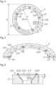
- the scale element 2 is shown in a top view.
- the scale element 2 has a ring-shaped or circular shape with an inner diameter d and an outer diameter D.
- the scale element 2 consists of a substrate 2.1 ( Figure 5 ), which in the illustrated embodiment is made of circuit board material, i.e. of plastic, in particular of epoxy resin, and on which two graduation tracks 2.2, 2.3 are arranged.
- the graduation tracks 2.2, 2.3 are ring-shaped and arranged concentrically with respect to the axis A with different radii on the substrate 2.1, so that the first graduation track 2.2 runs along the second graduation circle line C2 and the second graduation track 2.3 runs along the first graduation circle line C1.
- the graduation tracks 2.2, 2.3 comprise graduation structures each consisting of a periodic sequence of electrically conductive graduation regions 2.21, 2.31 and non-conductive graduation regions 2.22, 2.32 arranged alternately along the circumferential direction x, wherein the electrically conductive graduation regions 2.21, 2.31 are each formed from a layer of electrically conductive material. The thickness of this layer is 18 ⁇ m. In the example shown, copper was applied to the substrate 2.1 as the material for the electrically conductive graduation areas 2.21, 2.31. In the non-conductive graduation areas 2.22, 2.32, however, the substrate 2.1 is not coated. The arrangement with two graduation tracks 2.2, 2.3 allows the angular position of the scale element 2 to be determined absolutely.
- the outer graduation track 2.3 of the scale element 2 has the larger number of respective graduation areas 2.31, 2.32 along the circumferential direction x, so that the greater resolution with regard to the measurement of the angular position can be achieved through this.
- the second (outer) graduation track 2.3 has an even multiple of the first period length ⁇ 1, namely 32, corresponding to the sum s + t + v + w, which is used for the design of the geometry the first and third receiver conductor tracks 1.1121, 1.1321.
- the first (inner) division track 2.2 has the smaller number of respective division areas 2.31, 2.32 along the circumferential direction x, here 15. This corresponds to the sum p + q + m + n, which is decisive for the design of the second receiver conductor tracks 1.1221 and fourth receiver conductor tracks 1.1421.
- the electrically conductive division areas 2.21 of the first (inner) division track 2.2 each have an opening 2.211, so that the layer of electrically conductive material is open at this point or the substrate 2.1 is not coated in this area.
- the electrically conductive division areas 2.21 are designed or arranged such that the opening 2.211 is surrounded by the electrically conductive division area 2.21.
- the openings 2.211 are arranged such that they are each at the same distance from the center M and are arranged equidistantly (here at a distance of 24° each) along the second division circle line C2 in the circumferential direction x.
- the electrically conductive material surrounds the opening 2.211 so that webs 2.212 (see Figure 6 ) made of electrically conductive material and there is a closed contour made of electrically conductive material around the opening 2.211.
- holes 2.11 are arranged in the substrate 2.1 through an opening 2.211.
- the holes 2.11 are therefore arranged along the first (inner) division track 2.2 or along the second division circle line C2 in the substrate 2.1.
- five holes 2.11 are provided, each of which has the same distance from the center M and is arranged equidistantly (here at a distance of 72°) along the second division circle line C2.
- the bore 2.11 is designed here as a stepped through-bore.
- the bore 2.11 has a conical region 2.111, which is produced, for example, by countersinking.
- the conical region 2.111 is set back by a dimension h with respect to the surface of the substrate 2.1 or in the axial direction.
- a fastening element 2.4 can be arranged in the respective bore 2.11, which is designed here as a screw (in particular a countersunk screw), wherein the fastening element 2.4 is set back with respect to the surface of the substrate 2.1 and with respect to the surface of the respective electrically conductive graduation region 2.21.
- the fastening element 2.4 is used to fasten the scale element 2 to a machine part and is made of steel here and is therefore electrically conductive.
- the scanning element 1 and the scale element 2 face each other with an axial distance or air gap, so that when there is a relative rotation between the scale element 2 and the scanning element 1, a signal dependent on the respective angular position can be generated in the receiver conductor tracks 1.1121, 1.1221, 1.1321, 1.1421 by induction effects.
- the prerequisite for the formation of corresponding signals is that the excitation tracks 1.111, 1.121, 1.131, 1.141 generate a temporally changing electromagnetic excitation field in the area of the respective scanned graduation structures.
- the excitation tracks 1.111, 1.121, 1.131, 1.141 are designed as several planar-parallel individual conductor tracks through which current flows.
- the scanning element 1 has an electronic circuit with the electronic components 1.2, which are electrically connected to one another.
- the electronic circuit can also comprise an ASIC component, for example.
- the signals generated by the receiver tracks 1.112, 1.122, 1.132, 1.142 are further processed with the aid of some of the electronic components 1.2, which form an evaluation circuit.
- This electronic circuit of the scanning element 1 not only works as an evaluation element, but also as an excitation control element, under whose control the excitation current is generated or produced, which then flows through the excitation tracks 1.111, 1.121, 1.131, 1.141.
- the excitation tracks 1.111, 1.121, 1.131, 1.141 are energized by one and the same excitation control element.
- the excitation tracks 1.111, 1.121, 1.131, 1.141 are energized, a tube- or cylinder-shaped electromagnetic field is formed around the excitation tracks 1.111, 1.121, 1.131, 1.141.
- the field lines of the resulting electromagnetic field run around the excitation tracks 1.111, 1.121, 1.131, 1.141, with the direction of the field lines depending in a known manner on the direction of the current in the excitation tracks 1.111, 1.121, 1.131, 1.141.
- Eddy currents are induced in the area of the electrically conductive division areas 2.21, 2.31, so that a modulation of the field is achieved in each case depending on the angular position. Accordingly, the relative angular position can be measured by the receiver tracks 1.112, 1.122, 1.132, 1.142.
- the special design of the first electrically conductive graduation areas 2.21 in particular the positioning and dimensioning of the openings 2.211, ensures a suitable formation of the eddy currents that can flow around the opening 2.211 over 360°, in particular in the webs 2.212 made of electrically conductive material.
- the invention therefore makes it possible to achieve a comparatively compact design of the scale element 2 without noticeably reducing the measurement accuracy.
- the fastening elements 2.4 are integrated in the first graduation track 2.2, they do not affect the measurement result.
- those electrically conductive division areas 2.21 that do not have a bore have the same opening 2.211 as the division areas 2.21 with the bores 2.11 and with the fastening elements 2.4.
- the fastening elements 2.4 are set back in the axial direction.
Landscapes
- Physics & Mathematics (AREA)
- General Physics & Mathematics (AREA)
- Transmission And Conversion Of Sensor Element Output (AREA)
- Measurement Of Length, Angles, Or The Like Using Electric Or Magnetic Means (AREA)
Abstract
Description
- Die Erfindung betrifft ein Skalenelement für eine induktive Positionsmesseinrichtung gemäß dem Anspruch 1 zur Bestimmung einer Winkellage oder einer Linearposition des Skalenelements relativ zu einem Abtastelement.
- Induktive Positionsmesseinrichtungen werden beispielsweise als Winkelmesseinrichtungen zur Bestimmung einer Winkelposition von relativ zueinander drehbaren Maschinenteilen verwendet. Bei induktiven Positionsmesseinrichtungen sind häufig Erregerspuren und Empfängerspuren etwa in Form von Leiterbahnen auf einer gemeinsamen meist mehrlagigen Leiterplatte aufgebracht, die beispielsweise mit einem Stator der Positionsmesseinrichtung fest verbunden ist. Dieser Leiterplatte gegenüber befindet sich ein Skalenelement, auf dem Teilungsstrukturen aufgebracht sind, und welches mit einem beweglichen Teil der Positionsmesseinrichtung fest verbunden ist. Wenn an den Erregerspuren ein zeitlich wechselnder elektrischer Erregerstrom angelegt wird, werden in den Empfängerspuren während der Relativbewegung zwischen dem Skalenelement und dem Abtastelement von der Position abhängige Signale erzeugt. Diese Signale werden dann in einer Auswerteelektronik weiterverarbeitet.
- Aus der
EP 3 929 539 A1 der Anmelderin ist ein Skalenelement für eine induktive Winkelmesseinrichtung bekannt. Das Skalenelement umfasst zwei Teilungsspuren, die jeweils aus einer periodischen Abfolge von alternierend angeordneten elektrisch leitfähigen Teilungsbereichen und nichtleitfähigen Teilungsbereichen bestehen. Befestigt wird das Skalenelement mit Hilfe von Befestigungsbohrungen. - Der Erfindung liegt die Aufgabe zugrunde ein kompaktes und kostengünstig herstellbares Skalenelement zu schaffen, das dennoch für eine vergleichsweise genau arbeitende induktive Positionsmesseinrichtung verwendbar ist.
- Diese Aufgabe wird erfindungsgemäß durch die Merkmale des Anspruches 1 gelöst.
- Das Skalenelement, welches für eine induktive Positionsmesseinrichtung geeignet und bestimmt ist, umfasst ein Substrat, auf dem eine Teilungsspur angeordnet ist. Die Teilungsspur ist entlang einer Messrichtung aus einer periodischen Abfolge von alternierend angeordneten elektrisch leitfähigen Teilungsbereichen und vergleichsweise nichtleitfähigen Teilungsbereichen gebildet, wobei die elektrisch leitfähigen Teilungsbereiche jeweils aus einer Schicht aus elektrisch leitfähigem Material gebildet sind. Weiterhin ist im Substrat zumindest eine Bohrung angeordnet und vorgesehen, die dazu geeignet ist das Skalenelement an einem Maschinenteil zu befestigen. Die elektrisch leitfähigen Teilungsbereiche weisen jeweils eine Öffnung auf, wobei das elektrisch leitfähige Material die Öffnung umschließt: Zudem ist zumindest in einem der elektrisch leitfähigen Teilungsbereiche durch die Öffnung hindurch die Bohrung im Substrat angeordnet.
- Die elektrisch leitfähigen Teilungsbereiche sind also aus einer Schicht aus elektrisch leitfähigem Material gebildet. Die vergleichsweise nichtleitfähigen Teilungsbereiche können etwa aus Kunststoff (z. B. aus Leiterplattenmaterial) gebildet sein. Das Skalenelement kann als Substrat vorzugsweise Leiterplattenmaterial aus Kunststoff aufweisen. Alternativ kann das Substrat aus einem Schichtkörper gebildet sein, welcher eine relativ dicke Stahlschicht und eine nichtleitende Schicht (z.B. Kunststoffschicht) umfasst, wobei die Stahlschicht auf der von den Teilungsbereichen abgewandten Seite des Skalenelements angeordnet ist. Der oben genannte Begriff "vergleichsweise nichtleitfähig" bezieht sich also auf das Verhältnis der elektrischen Leitfähigkeiten der Materialien der alternierend angeordneten Teilungsbereiche. Dieses Verhältnis kann insbesondere größer als 10 oder größer als 50 sein. Die Schicht aus elektrisch leitfähigem Material der elektrisch leitfähigen Teilungsbereiche ist mit Vorteil größer als 12 µm beziehungsweise 0,012 mm. Andererseits ist es insbesondere aus wirtschaftlichen Gründen von Vorteil, wenn die Schicht dünner als 1 mm, insbesondere dünner als 0,5 mm, vorteilhafterweise dünner als 0,1 mm ist.
- Unter dem Begriff Bohrung ist im Folgenden ein Loch zu verstehen, das nicht zwingend rund ausgestaltet sein muss. Insbesondere kann die Bohrung hier auch eckig oder elliptisch ausgestaltet sein und beispielsweise durch einen Stanz- oder Fräsprozess hergestellt worden sein.
- Das Skalenelement dient in einer Winkelmesseinrichtung dazu, dass eine Winkelstellung relativ zu einem Abtastelement bestimmt werden kann. Dabei ist das Skalenelement relativ zum Abtastelement um eine Achse drehbar angeordnet, so dass die Messrichtung die Umfangsrichtung bezogen auf die Achse darstellt.
- Mit Vorteil ist die Teilungsspur ringförmig beziehungsweise kreisringförmig ausgebildet, wobei insbesondere der Mittelpunkt der ringförmigen Teilungsspur auf der Achse liegt.
- In weiterer Ausgestaltung der Erfindung sind die Öffnungen in den elektrisch leitfähigen Teilungsbereichen geometrisch gleich ausgestaltet.
- Vorteilhafterweise erstreckt sich die Teilungsspur entlang einer Teilungskreislinie mit dem Mittelpunkt, der insbesondere auf der Achse liegt, wobei die Öffnungen so angeordnet sind, dass diese jeweils den gleichen Abstand zum Mittelpunkt aufweisen und entlang der Teilungskreislinie äquidistant angeordnet sind.
- Mit Vorteil umfasst das Skalenelement mehrere elektrisch leitfähige Teilungsbereiche, welche Bohrungen aufweisen. Die Bohrungen sind so angeordnet, dass diese jeweils den gleichen Abstand zum Mittelpunkt aufweisen und entlang der Teilungskreislinie äquidistant angeordnet sind.
- Die Abstände zwischen den Öffnungen beziehungsweise zwischen den Bohrungen werden hier in Grad angegeben und beziehen sich auf einen jeweiligen Zentriwinkel um die Achse beziehungsweise um den Mittelpunkt der Teilungskreislinie.
- Vorteilhafterweise weist das ringförmig ausgestaltete Skalenelement einen Innendurchmesser d und einen Außendurchmesser D auf, wobei gilt D/d < 3. Demnach weist also das Skalenelement beispielsweise einen relativ großen Innendurchmesser d auf.
- In weiterer Ausgestaltung der Erfindung umfasst das Skalenelement zumindest ein Befestigungselement, das in der Bohrung angeordnet ist. Dabei kann das Befestigungselement bezogen auf die axiale Richtung bündig oder zurückgesetzt bezüglich der elektrisch leitfähigen Teilungsbereiche angeordnet sein und jedenfalls nicht in axialer Richtung über die Oberfläche der elektrisch leitfähigen Teilungsbereiche ragen. Unter axialer Richtung ist im Folgenden eine Richtung zu verstehen, die parallel zur Achse orientiert ist.
- Insbesondere ist das Befestigungselement aus elektrisch leitfähigem Material hergestellt und kann als eine Schraube ausgestaltet sein. Alternativ kann als Befestigungselement ein Niet, ein Metallstift, ein Spannstift oder dergleichen dienen, wobei es vorteilhaft sein kann, wenn das Skalenelement zusätzlich noch an dem Maschinenteil, an dem es befestigt wird, verklebt wird. Das Befestigungselement kann insbesondere zur Herstellung eines Formschlusses dienen, was für eine funktional sichere Anordnung von Bedeutung ist. Gleichzeitig kann das Befestigungselement zur Zentrierung des Skalenelements dienen. So ist beispielsweise auch eine Konfiguration möglich, bei der in die Bohrungen Zentriernasen beziehungsweise Zentrierschneiden gepresst werden und das Skalenelement zusätzlich mit einer Klebeverbindung fixiert wird.
- Mit Vorteil umfasst das Skalenelement mehrere Befestigungselemente, wobei das Skalenelement mehrere der elektrisch leitfähigen Teilungsbereiche umfasst, welche Bohrungen aufweisen, in denen die Befestigungselemente angeordnet sind.
- Gemäß einem weiteren Aspekt umfasst die Erfindung auch eine induktive Positionsmesseinrichtung mit dem Skalenelement und mit einem Abtastelement.
- Vorteilhafte Ausbildungen der Erfindung entnimmt man den abhängigen Ansprüchen.
- Weitere Einzelheiten und Vorteile des erfindungsgemäßen Abtastelements ergeben sich aus der nachfolgenden Beschreibung eines Ausführungsbeispiels anhand der beiliegenden Figuren.
-
- Figur 1
- eine perspektivische Ansicht einer Winkelmesseinrichtung umfassend ein Abtastelement und ein Skalenelement,
- Figur 2
- eine Draufsicht auf eine Seite des Abtastelements,
- Figur 3
- eine Draufsicht auf das Skalenelement, bei der unter anderem mehrere Empfängerleiterbahnen ausgeblendet sind,
- Figur 4
- eine Draufsicht auf eine Seite eines Skalenelements
- Figur 5
- eine perspektivische Schnittdarstellung des Skalenelements
- Figur 6
- eine Schnittdarstellung durch eine Bohrung des Skalenelements.
- Die Erfindung wird gemäß der
Figur 1 anhand einer Winkelmesseinrichtung beschrieben, welche ein Abtastelement 1 aufweist, das zur Erfassung einer Winkelstellung eines Skalenelements 2 verwendet werden kann. Das Skalenelement 2 ist um eine Achse A relativ zum Abtastelement 1 drehbar angeordnet. Eine derartige Winkelmesseinrichtung kann beispielsweise in einer Antriebseinrichtung verwendet werden, wobei das Skalenelement 2 dann etwa mit einer Antriebswelle eines Motors drehfest verbunden wird. - Das Abtastelement 1 umfasst eine Leiterplatte 1.1, welche mehrere Lagen aufweist, sowie elektronische Bauteile 1.2, die auf der Leiterplatte 1.1 montiert sind. Die Leiterplatte 1.1 umfasst zudem einen Rahmen 1.3 als mechanisch tragende Struktur.
- Wie auch in der
Figur 2 gezeigt, hat die Leiterplatte 1.1 die Form eines Kreisringsegments, das ca. über 300° umlaufend ausgestaltet ist und entsprechend eine Öffnung aufweist. Um diese Leiterplatte 1.1 außen herum angeordnet ist der geschlossene und im wesentlichen ringförmige Rahmen 1.3, hier aus Metall, befestigt, der insbesondere zur mechanischen Verstärkung des Abtastelements 1 dient und Befestigungsbereiche 1.31, hier in Form von Bohrungen, aufweist. Im Bereich der Öffnung der Leiterplatte 1.1 verlaufen parallel zu den Stirnseiten der Leiterplatte 1.1 im Wesentlichen in radialer Richtung Stege 1.32 des Rahmens 1.3. Ein weiterer Steg 1.33 des Rahmens 1.3 verläuft über einen Winkel von etwa 60° in einer Kreissegmentkontur. - Das Abtastelement 1 dient zur Abtastung des ersten Skalenelements 2. Im vorgestellten Ausführungsbeispiel sind die elektronischen Bauteile 1.2 nur auf einer Seite der Leiterplatte 1.1 montiert, nämlich auf der vom Skalenelement 2 abgewandten Seite. Alternativ oder ergänzend könnten aber auch beide Seiten der Leiterplatte 1.1 mit elektronischen Bauteilen 1.2 bestückt werden.
- Zur Bestimmung der Winkelinformationen weist gemäß der
Figur 2 die Leiterplatte 1.1 eine erste Detektoreinheit 1.11, und eine zweite Detektoreinheit 1.12, eine dritte Detektoreinheit 1.13 und eine vierte Detektoreinheit 1.14 auf. Die Detektoreinheiten 1.11 bis 1.14 haben jeweils eine ringsegmentartige Form, wobei für alle Detektoreinheiten 1.11 bis 1.14 gilt, dass der Mittelpunkt M der jeweiligen ringsegmentartigen Form auf der Achse A liegt. Demnach liegen die Detektoreinheiten 1.11 bis 1.14 bezüglich des Mittelpunkts M in erster Näherung konzentrisch einander gegenüber. - Die erste Detektoreinheit 1.11 umfasst eine erste Erregerspur 1.111 und eine erste Empfängerspur 1.112. Ebenso umfassen die zweite Detektoreinheit 1.12 eine zweite Erregerspur 1.121 und eine zweite Empfängerspur 1.122, die dritte Detektoreinheit 1.13 eine dritte Erregerspur 1.131 und eine dritte Empfängerspur 1.132 sowie die vierte Detektoreinheit 1.14 eine vierte Erregerspur 1.141 und eine vierte Empfängerspur 1.142.
- Die Erregerspuren 1.111, 1.121, 1.131, 1.141 umschließen jeweils eine der Empfängerspuren 1.112, 1.122, 1.132, 1.142. Sowohl die Erregerspuren 1.111, 1.121, 1.131, 1.141, als auch die Empfängerspuren 1.112, 1.122, 1.132, 1.142 verlaufen entlang einer Umfangsrichtung x.
- Jede der Empfängerspuren 1.112, 1.122, 1.132, 1.142 umfasst im vorgestellten Ausführungsbeispiel jeweils vier Empfängerleiterbahnen 1.1121, 1.1221, 1.1321, 1.1421, die in Umfangsrichtung x versetzt angeordnet sind, so dass diese dem Versatz entsprechend vier phasenverschobene Signale liefern können. Im vorgestellten Ausführungsbeispiel sind innerhalb einer Empfängerspur 1.112, 1.122, 1.132, 1.142 benachbarte Empfängerleiterbahnen 1.1121, 1.1221, 1.1321, 1.1421 um 1/8 der vollen Sinusperiode (um π/4 oder 45° entlang der Umfangsrichtung x) zueinander versetzt angeordnet.
- In den Figuren sind diejenigen Empfängerleiterbahnen 1.1121, 1.1221, 1.1321, 1.1421, welche ein und derselben Empfängerspur 1.112, 1.122, 1.132, 1.142 angehören, mit nur einem Bezugszeichen versehen. Folglich sind also beispielsweise alle Empfängerleiterbahnen 1.1121 der ersten Empfängerspur 1.112 mit nur einem Bezugszeichen versehen. Zudem verlaufen die ersten Empfängerleiterbahnen 1.1121, 1.1221, 1.1321, 1.1421 der Detektoreinheiten 1.11 bis 1.14 mit Vias verbunden in unterschiedlichen Lagen der Leiterplatte 1.1, so dass an Kreuzungspunkten unerwünschte Kurzschlüsse vermieden werden. Wenngleich genau genommen jede der Empfängerleiterbahnen 1.1121, 1.1221, 1.1321, 1.1421 aus vielen Leiterstücken besteht, die jeweils auf zwei Ebenen beziehungsweise Lagen verteilt und aneinandergereiht sind, wird im Folgenden eine derartige Struktur zusammenfassend als eine Empfängerleiterbahn 1.1121, 1.1221, 1.1321, 1.1421 bezeichnet.
- In der
Figur 3 ist der Übersichtlichkeit halber jeweils nur eine Empfängerleiterbahn 1.1121, 1.1221, 1.1321, 1.1421 der Empfängerspuren 1.112, 1.122, 1.132, 1.142 gezeigt. Die Folgenden Erläuterungen werden anhand dieser Darstellung einer einzelnen Empfängerleiterbahn 1.1121, 1.1221, 1.1321, 1.1421 vorgenommen, wobei die Gegebenheiten auch für die entsprechend zueinander gehörigen phasenverschobenen Empfängerleiterbahnen 1.1121, 1.1221, 1.1321, 1.1421 zutreffen. - Die erste Empfängerleiterbahn 1.1121 und die dritte Empfängerleiterbahn 1.1321 verlaufen entlang einer ersten Kreislinie K1, die einen ersten Radius R aufweist. Die zweite Empfängerleiterbahn 1.1221 und die vierte Empfängerleiterbahn 1.1421 verlaufen entlang einer zweiten Kreislinie K2, die einen zweiten Radius r aufweist, wobei der zweite Radius r kleiner ist als der erste Radius R, so dass gilt:

- Beide Kreislinien K1, K2 haben denselben Mittelpunkt M. Die Empfängerleiterbahnen 1.1121, 1.1221, 1.1321, 1.1421 weisen einen räumlich periodischen Verlauf auf, der im Wesentlichen sinusförmig beziehungsweise sinusartig ausgestaltet ist. Die ersten Empfängerleiterbahnen 1.1121 der ersten Empfängerspur 1.112 und die dritten Empfängerleiterbahnen 1.1321 der dritten Empfängerspur 1.132 weisen über ihren Verlauf hinweg eine konstante erste Periodenlänge λ1 auf. Dagegen weisen die zweiten Empfängerleiterbahnen 1.1221 der zweiten Empfängerspur 1.122 und die vierten Empfängerleiterbahnen 1.1421 der vierten Empfängerspur 1.142 über ihren Verlauf hinweg eine konstante zweite Periodenlänge λ2 auf. Hier ist die zweite Periodenlänge λ2 größer als die erste Periodenlänge λ1.

- Die Periodenlängen λ1, λ2 werden hier in Grad angegeben und beziehen sich auf einen jeweiligen Zentriwinkel um die Achse A beziehungsweise um den Mittelpunkt M. Im vorgestellten Ausführungsbeispiel beträgt
die erste Periodenlänge: λ1 = 360°/32 = 11,25° und die zweite Periodenlänge: λ2 = 360°/15 = 24°. - Demzufolge ist also die erste Periodenlänge λ1 ein ganzzahliger erster Teiler S von 360°, wobei hier gilt S = 32,

- Analog ist die zweite Periodenlänge λ2 ein ganzzahliger zweiter Teiler T von 360°, wobei hier gilt T = 15,

- Der erste Teiler S und der zweite Teiler T sind teilerfremd:

- Die zweiten Empfängerleiterbahnen 1.1221 und die vierten Empfängerleiterbahnen 1.1421 sind so angeordnet, dass zwischen diesen in Umfangsrichtung x jeweils eine erste Lücke G24 und eine zweite Lücke L24 vorliegt, wobei sich die zweiten Empfängerleiterbahnen 1.1221 über eine zweite Bogenlänge α2 erstrecken und die vierten Empfängerleiterbahnen 1.1421 über eine vierte Bogenlänge α4 erstrecken, dabei gilt im vorgestellten Ausführungsbeispiel:



- Hier ist p = q = 4, demnach beträgt α2 = 4 x 24° = 96° = α4. Folglich erstrecken sich die zweiten Empfängerleiterbahnen 1.1221 und die die vierten Empfängerleiterbahnen 1.1421 also jeweils über eine gleich große Bogenlänge α2, α4, die hier vier zweiten Periodenlängen λ2 entspricht.
- Die erste Lücke G24 erstreckt sich über eine erste Lückenlänge β24 und die zweite Lücke L24 erstreckt sich über eine zweite Lückenlänge y24. Die erste Lückenlänge β24 beträgt ein erstes Vielfaches m der zweiten Periodenlänge λ2, wobei hier m = 3 gilt. Zudem beträgt die zweite Lückenlänge y24 ein zweites Vielfaches n, im vorgestellten Ausführungsbeispiel nimmt n den Wert 4 an. Grundsätzlich können für m und n Natürliche Zahlen größer Null eingesetzt werden. Es gilt:


- Außerdem gilt, dass die Summe aus m und n eine ungerade Zahl ergibt, also


- Im Hinblick auf die Bildung eines absoluten Winkelmesswertes, insbesondere zur Bildung eines Anschlusses beziehungsweise auf eine Verknüpfung mit der ersten und dritten Empfängerspur 1.112, 1.132, ist es grundsätzlich vorteilhaft, wenn die Summe aus der zweiten Bogenlänge α2, der vierten Bogenlänge α4, der ersten Lückenlänge β24 und der zweiten Lückenlänge y24 ein ungeradzahliges Vielfaches der zweiten Periodenlänge λ2 beträgt, beziehungsweise der zweite Teiler T (hier 15) eine ungerade Zahl ist.


- Es ist vorteilhaft, wenn sich die zweiten Empfängerleiterbahnen 1.1221 und die vierten Empfängerleiterbahnen 1.1421 jeweils über eine gleich große Bogenlänge α2, α4 erstrecken (p = q). Folglich müssen die erste Lückenlänge β24 und die zweite Lückenlänge y24 unterschiedlich groß sein, sofern die Bogenlängen α2, α4 und die Lückenlängen β24, y24 jeweils ein Vielfaches der zweiten Periodenlänge λ2 betragen und deren Summe ein ungeradzahliges Vielfaches der zweiten Periodenlänge λ2 ist. Im vorgestellten Ausführungsbeispiel ist die erste Lückenlänge β24 kleiner als die zweite Lückenlänge y24, so dass gilt:


- Vorteilhafterweise ist der Unterschied zwischen der ersten Lückenlänge β24 und der zweiten Lückenlänge y24 minimal, so dass gilt:


- Die ersten Empfängerleiterbahnen 1.1121 und die dritten Empfängerleiterbahnen 1.1321 sind so angeordnet, dass zwischen diesen in Umfangsrichtung x eine dritte Lücke G13 und eine vierte Lücke L13 vorliegt. Zudem erstrecken sich die ersten Empfängerleiterbahnen 1.1121 über eine erste Bogenlänge α1, wobei gilt:

- Die dritten Empfängerleiterbahnen 1.1321 erstrecken sich jeweils über eine dritte Bogenlänge α3, wobei gilt:


- Im vorgestellten Ausführungsbeispiel ist s = t = 8, so dass also α1 = 8 x 11,25° = 90° = α3 beträgt. Die ersten Empfängerleiterbahnen 1.1121 und die dritten Empfängerleiterbahnen 1.1321 erstrecken sich also jeweils über eine gleich große Bogenlänge α1, α3, die hier acht ersten Periodenlängen λ1 entspricht.
- Die dritte Lücke G13 erstreckt sich über eine dritte Lückenlänge β13 und die vierte Lücke L13 erstreckt sich über eine vierte Lückenlänge y13. Die dritte Lückenlänge β13 beträgt ein drittes Vielfaches v der ersten Periodenlänge λ1. Zudem beträgt die vierte Lückenlänge y13 ein viertes Vielfaches w, im vorgestellten Ausführungsbeispiel nehmen v und w jeweils den Wert 8 an. Grundsätzlich können für v und w Natürliche Zahlen größer Null eingesetzt werden. Es gilt:


- Außerdem gilt im vorgestellten Ausführungsbeispiel, dass v und w eine gerade Zahl sind. Für die Bildung eines absoluten Winkelmesswertes ist es grundsätzlich vorteilhaft, wenn die Summe aus der ersten Bogenlänge α1, der dritten Bogenlänge α3, der dritten Lückenlänge β13 und der vierten Lückenlänge y13 ein geradzahliges Vielfaches der ersten Periodenlänge λ1 beträgt, beziehungsweise der erste Teiler S (hier 32) eine gerade Zahl ist.



- Die dritte Lücke G13 und die vierte Lücke L13 erstrecken sich über ein Vielfaches der ersten Periodenlänge λ1. Zudem sind die dritte Lücke G13 und die vierte Lücke L13 gleich groß, so dass sich also die dritte Lücke G13 über 90° oder acht erste Periodenlängen λ1 erstreckt und die vierte Lücke L13 ebenfalls über 90°.
- Der Verlauf der zweiten Empfängerleiterbahnen 1.1221 weist entlang der Umfangsrichtung x jeweils unterschiedliche Amplituden j2a, J2b auf. Es liegen also jeweils im Bereich der maximalen Auslenkung unterschiedliche Abstände zwischen der zweiten Kreislinie K2 und der sinusartig verlaufenden zweiten Empfängerleiterbahn 1.1221 vor. Insbesondere weist der Verlauf der zweiten Empfängerleiterbahnen 1.1221 innerhalb eines ersten Abschnittes 2a die erste Amplitude j2a auf, wobei sich der erste Abschnitt 2a ausgehend von dem an die erste Lücke G24 angrenzenden Ende der zweiten Empfängerleiterbahn 1.1221 über einen ersten Winkel α2a erstreckt. Innerhalb eines zweiten Abschnittes 2b weist der Verlauf der zweiten Empfängerleiterbahnen 1.1221 eine zweite Amplitude J2b auf, wobei sich der zweite Abschnitt 2b ausgehend von dem an der zweiten Lücke L24 angrenzenden anderen Ende der zweiten Empfängerleiterbahn 1.1221 über einen zweiten Winkel α2b erstreckt. Dabei sind der erste und der zweite Winkel α2a, α2b jeweils kleiner oder gleich der halben zweiten Bogenlänge α2. Die erste Amplitude j2a ist kleiner als die zweite Amplitude J2b.
- Eine analoge Betrachtung ist auch für die vierten Empfängerleiterbahnen 1.1421 gültig. Demnach weist der Verlauf der vierten Empfängerleiterbahnen 1.1421 entlang der Umfangsrichtung x jeweils unterschiedliche Amplituden j4a, J4b auf. Es liegen also jeweils im Bereich der maximalen Auslenkung unterschiedliche Abstände zwischen der zweiten Kreislinie K2 und der sinusartig verlaufenden vierten Empfängerleiterbahnen 1.1421 vor. Insbesondere weist der Verlauf der vierten Empfängerleiterbahnen 1.1421 innerhalb eines dritten Abschnittes 4a die dritte Amplitude j4a auf, wobei sich der dritte Abschnitt 4a ausgehend von dem an die erste Lücke G24 angrenzenden Ende der vierten Empfängerleiterbahn 1.1421 über einen ersten Winkel α4a erstreckt. Innerhalb eines vierten Abschnittes 4b weist der Verlauf der vierten Empfängerleiterbahnen 1.1421 eine vierte Amplitude J4b auf, wobei sich der vierte Abschnitt 4b ausgehend von dem an der zweiten Lücke L24 angrenzenden anderen Ende der vierten Empfängerleiterbahn 1.1421 über einen vierten Winkel α4b erstreckt. Dabei sind der erste und der vierte Winkel α4a, α4b jeweils kleiner oder gleich der halben vierten Bogenlänge α4 und die dritte
- Amplitude j4a ist kleiner als die vierte Amplitude J4b. Demnach gilt im vorgestellten Ausführungsbeispiel:


- Im vorgestellten Ausführungsbeispiel weisen die zweiten und die vierten Empfängerleiterbahnen 1.1221,1.1421 nicht nur zwei unterschiedliche Amplituden j4a, J4b auf. In den Bereichen zwischen den beiden genannten Amplituden j4a, J4b befinden sich innerhalb jeweils einer zweiten Periodenlänge λ2 Amplituden, die eine Zwischengröße aufweisen, also kleiner sind als die zweite Amplitude J2b beziehungsweise vierte Amplitude J4b und größer sind als die erste Amplitude j2a beziehungsweise dritte Amplitude j4a.
- Im vorgestellten Ausführungsbeispiel ist die zwischen den zweiten Empfängerleiterbahnen 1.1221 aufgespannte Fläche, also die Summe der Einzelflächen zwischen den sinusförmigen zweiten Empfängerleiterbahnen 1.1221 (Summe aller linsenförmigen Teilflächen), ähnlich oder gleich groß wie die von den vierten Empfängerleiterbahnen 1.1421 aufgespannte Fläche.
- Die Empfängerleiterbahnen 1.1121, 1.1221, 1.1321, 1.1421 sind elektrisch so verschaltet, dass diese zum einen 0° und 90°-Signale liefern und zum anderen 45° und 135°-Signale. Aus den 0° und 90°-Signalen kann ein erstes Positionssignal bestimmt werden und aus den 45° und 135°-Signalen kann ein bezüglich des ersten Positionssignals redundantes zweites Positionssignal bestimmt werden. Zudem sind die ersten Empfängerleiterbahnen 1.1121 der ersten Empfängerspur 1.112 und die dritten Empfängerleiterbahnen 1.1321 der dritten Empfängerspur 1.132 analog seriell miteinander verschaltet. Ebenso sind die zweiten Empfängerleiterbahnen 1.1221 der zweiten Empfängerspur 1.122 und die vierten Empfängerleiterbahnen 1.1421 der vierten Empfängerspur 1.142 analog seriell miteinander verschaltet. Die Auswertung der von den miteinander verschalteten Empfängerleiterbahnen 1.1121, 1.1221, 1.1321, 1.1421 erzeugten Signale erfolgt über einen gemeinsamen Auswerte-ASIC, so dass auf diese Weise eine absolute Position errechnet wird.
- In der
Figur 4 ist das Skalenelement 2 in einer Draufsicht gezeigt. Das Skalenelement 2 weist eine ringförmige beziehungsweise kreisringförmige Gestalt auf mit einem Innendurchmesser d und einem Außendurchmesser D. Im vorgestellten Ausführungsbeispiel ist der Innendurchmesser d verhältnismäßig groß, so dass hier gilt: D/d = 1,4. - Das Skalenelement 2 besteht aus einem Substrat 2.1 (
Figur 5 ), welches im dargestellten Ausführungsbeispiel aus Leiterplattenmaterial, also aus Kunststoff, insbesondere aus Epoxidharz hergestellt ist und auf dem zwei Teilungsspuren 2.2, 2.3 angeordnet sind. Die Teilungsspuren 2.2, 2.3 sind ringförmig ausgebildet und bezüglich der Achse A konzentrisch mit unterschiedlichen Radien auf dem Substrat 2.1 angeordnet, so dass die erste Teilungsspur 2.2 entlang der zweiten Teilungskreislinie C2 verläuft und die zweite Teilungsspur 2.3 entlang der ersten Teilungskreislinie C1 verläuft. Die Teilungsspuren 2.2, 2.3 umfassen Teilungsstrukturen bestehend aus jeweils einer periodischen Abfolge von entlang der Umfangsrichtung x alternierend angeordneten elektrisch leitfähigen Teilungsbereichen 2.21, 2.31 und nichtleitfähigen Teilungsbereichen 2.22, 2.32, wobei die elektrisch leitfähigen Teilungsbereiche 2.21, 2.31, jeweils aus einer Schicht aus elektrisch leitfähigem Material gebildet sind. Die Dicke dieser Schicht beträgt hier 18 µm. Als Material für die elektrisch leitfähigen Teilungsbereiche 2.21, 2.31 wurde im gezeigten Beispiel Kupfer auf das Substrat 2.1 aufgebracht. In den nichtleitfähigen Teilungsbereichen 2.22, 2.32 ist das Substrat 2.1 dagegen nicht beschichtet. Durch die Anordnung mit jeweils zwei Teilungsspuren 2.2, 2.3 kann die Winkelstellung des Skalenelements 2 absolut bestimmt werden. Die äußere Teilungsspur 2.3 des Skalenelements 2 weist die größere Anzahl von jeweiligen Teilungsbereichen 2.31, 2.32 entlang der Umfangsrichtung x auf, so dass durch diese die größere Auflösung bezüglich der Messung der Winkelstellung erzielbar ist. Im vorgestellten Ausführungsbeispiel weist die zweite (äußere) Teilungsspur 2.3 ein geradzahliges Vielfaches der ersten Periodenlänge λ1 auf, nämlich 32, entsprechend der Summe s + t + v + w, die für die Auslegung der Geometrie der ersten und dritten Empfängerleiterbahnen 1.1121, 1.1321 zugrunde gelegt worden ist. Dagegen weist die erste (innere) Teilungsspur 2.2 die kleinere Anzahl von jeweiligen Teilungsbereichen 2.31, 2.32 entlang der Umfangsrichtung x auf, hier 15. Dies entspricht der Summe p + q + m + n, die für die Auslegung der zweiten Empfängerleiterbahnen 1.1221 und vierten Empfängerleiterbahnen 1.1421 maßgeblich ist. - Die elektrisch leitfähigen Teilungsbereiche 2.21 der ersten (inneren) Teilungsspur 2.2 weisen jeweils eine Öffnung 2.211 auf, so dass also die Schicht aus elektrisch leitendem Material an dieser Stelle geöffnet ist beziehungsweise das Substrat 2.1 in diesem Bereich nicht beschichtet ist. Die elektrisch leitfähigen Teilungsbereiche 2.21 sind so ausgestaltet beziehungsweise angeordnet, dass jeweils die Öffnung 2.211 von dem elektrisch leitfähigen Teilungsbereich 2.21 umschlossen ist. Die Öffnungen 2.211 sind so angeordnet, dass diese jeweils den gleichen Abstand zum Mittelpunkt M aufweisen, und entlang der zweiten Teilungskreislinie C2 in Umfangsrichtung x äquidistant (hier in einem Abstand von jeweils 24°) angeordnet sind. Das elektrisch leitfähige Material umschließt die Öffnung 2.211, so dass sich beidseitig um die Öffnung 2.211 herum Stege 2.212 (siehe
Figur 6 ) aus elektrisch leitfähigem Material befinden und um die Öffnung 2.211 herum eine geschlossene Kontur aus elektrisch leitfähigem Material vorliegt. - In einer Teilanzahl, hier fünf, der elektrisch leitfähigen Teilungsbereiche 2.21 sind jeweils durch eine Öffnung 2.211 hindurch Bohrungen 2.11 im Substrat 2.1 angeordnet. Die Bohrungen 2.11 sind also entlang der ersten (inneren) Teilungsspur 2.2 beziehungsweise entlang der zweiten Teilungskreislinie C2 im Substrat 2.1 angeordnet, im vorgestellten Ausführungsbeispiel sind fünf Bohrungen 2.11 vorgesehen, die jeweils den gleichen Abstand zum Mittelpunkt M aufweisen und entlang der zweiten Teilungskreislinie C2 äquidistant (hier in einem Abstand von 72°) angeordnet sind.
- In der
Figur 6 ist ein Detailschnitt durch einen Teil des Skalenelementes 2 im Bereich der ersten Teilungsspur 2.2 gezeigt, wobei in derFigur 6 die Dicke der Schicht aus elektrisch leitendem Material des elektrisch leitfähigen Teilungsbereichs 2.21 zur Erläuterung übertrieben groß dargestellt ist. Die Bohrung 2.11 ist hier jeweils als eine abgesetzte Durchgangsbohrung ausgestaltet. Insbesondere weist die Bohrung 2.11 einen konischen Bereich 2.111 auf, der beispielsweise durch eine Senkbearbeitung hergestellt wird. Der konische Bereich 2.111 ist bezüglich der Oberfläche des Substrats 2.1 beziehungsweise in axialer Richtung um ein Maß h zurückversetzt angeordnet. Dadurch kann in der jeweiligen Bohrung 2.11 ein Befestigungselement 2.4 angeordnet werden, das hier jeweils als eine Schraube (insbesondere Senkkopfschraube) ausgebildet ist, wobei das Befestigungselement 2.4 bezüglich der Oberfläche des Substrats 2.1 und bezüglich der Oberfläche des jeweiligen elektrisch leitfähigen Teilungsbereichs 2.21 zurückversetzt ist. Das Befestigungselement 2.4 dient zur Befestigung des Skalenelements 2 an einem Maschinenteil und ist hier aus Stahl gefertigt und demnach elektrisch leitend. - Im zusammengebauten Zustand stehen sich das Abtastelement 1 und das Skalenelement 2 mit axialem Abstand beziehungsweise Luftspalt gegenüber, so dass bei einer Relativdrehung zwischen dem Skalenelement 2 und dem Abtastelement 1 in den Empfängerleiterbahnen 1.1121, 1.1221, 1.1321, 1.1421 jeweils ein von der jeweiligen Winkelposition abhängiges Signal durch Induktionseffekte erzeugbar ist. Voraussetzung für die Bildung von entsprechenden Signalen ist, dass die Erregerspuren 1.111, 1.121, 1.131, 1.141 ein zeitlich wechselndes elektromagnetisches Erregerfeld im Bereich der jeweilig abgetasteten Teilungsstrukturen erzeugen. Im dargestellten Ausführungsbeispiel sind die Erregerspuren 1.111, 1.121, 1.131, 1.141 als mehrere planarparallele stromdurchflossene Einzel-Leiterbahnen ausgebildet. Das Abtastelement 1 weist eine elektronische Schaltung mit den elektronischen Bauteilen 1.2 auf, die miteinander elektrisch verbunden sind. Die elektronische Schaltung kann beispielsweise auch einen ASIC-Baustein umfassen. Die Signale, die von den Empfängerspuren 1.112, 1.122, 1.132, 1.142 erzeugt werden, werden mit Hilfe von einigen der elektronischen Bauteile 1.2, die eine Auswerteschaltung bilden, weiterverarbeitet. Diese elektronische Schaltung des Abtastelements 1 arbeitet nicht nur als Auswerteelement, sondern auch als Erregerkontrollelement, unter dessen Kontrolle der Erregerstrom generiert beziehungsweise erzeugt wird, welcher dann durch die Erregerspuren 1.111, 1.121, 1.131, 1.141 fließt. Somit werden die Erregerspuren 1.111, 1.121, 1.131, 1.141 durch ein und dasselbe Erregerkontrollelement bestromt.
- Werden die Erregerspuren 1.111, 1.121, 1.131, 1.141 bestromt, so bildet sich um die Erregerspuren 1.111, 1.121, 1.131, 1.141 ein schlauch- bzw. zylinderförmig orientiertes elektromagnetisches Feld aus. Die Feldlinien des resultierenden elektromagnetischen Feldes verlaufen um die Erregerspuren 1.111, 1.121, 1.131, 1.141, wobei die Richtung der Feldlinien in bekannter Art und Weise von der Stromrichtung in den Erregerspuren 1.111, 1.121, 1.131, 1.141 abhängt. Im Bereich der elektrisch leitfähigen Teilungsbereiche 2.21, 2.31 werden Wirbelströme induziert, so dass jeweils eine von der Winkelstellung abhängige Modulation des Feldes erreicht wird. Entsprechend kann durch die Empfängerspuren 1.112, 1.122, 1.132, 1.142 jeweils die relative Winkelstellung gemessen werden. Die spezielle Ausgestaltung der ersten elektrisch leitfähigen Teilungsbereiche 2.21, insbesondere die Positionierung und Dimensionierung der Öffnungen 2.211 stellt eine geeignete Ausbildung der Wirbelströme sicher, die um die Öffnung 2.211 über 360° herum insbesondere in den Stegen 2.212 aus elektrisch leitfähigem Material fließen können. Durch die Erfindung kann also eine vergleichsweise kompakte Bauweise des Skalenelementes 2 erreicht werden, ohne dass die Messgenauigkeit merklich reduziert wird. Denn obwohl die Befestigungselemente 2.4 in der ersten Teilungsspur 2.2 integriert sind, beeinträchtigen diese nicht das Messergebnis. Insbesondere ist es in diesem Zusammenhang auch von Vorteil, dass diejenigen elektrisch leitfähigen Teilungsbereiche 2.21, die keine Bohrung aufweisen die gleiche Öffnung 2.211 aufweisen, wie die Teilungsbereiche 2.21 mit den Bohrungen 2.11 und mit den Befestigungselementen 2.4. Zudem ist es auch vorteilhaft, dass die Befestigungselemente 2.4 in axialer Richtung zurückversetzt sind.
Claims (11)
- Skalenelement (2) für eine induktive Positionsmesseinrichtung, welches ein Substrat (2.1) aufweist, auf dem eine Teilungsspur (2.2) angeordnet ist, wobeidie Teilungsspur (2.2) entlang einer Messrichtung (x) aus einer periodischen Abfolge von alternierend angeordneten elektrisch leitfähigen Teilungsbereichen (2.21) und nichtleitfähigen Teilungsbereichen (2.22) gebildet ist, wobei die elektrisch leitfähigen Teilungsbereiche (2.21), jeweils aus einer Schicht aus elektrisch leitfähigem Material gebildet sind,im Substrat (2.1) zumindest eine Bohrung (2.11) angeordnet ist zur Befestigung des Skalenelements (2) an einem Maschinenteil,dadurch gekennzeichnet, dassdie elektrisch leitfähigen Teilungsbereiche (2.21) jeweils eine Öffnung (2.211) aufweisen, wobei das elektrisch leitfähige Material die Öffnung (2.211) umschließt, wobeizumindest in einem der elektrisch leitfähigen Teilungsbereiche (2.21) durch die Öffnung (2.211) hindurch die zumindest eine Bohrung (2.11) im Substrat (2.1) angeordnet ist.
- Skalenelement (2) gemäß dem Anspruch 1, wobei die Teilungsspur (2.2) ringförmig ausgebildet ist.
- Skalenelement (2) gemäß einem der vorhergehenden Ansprüche, wobei die Öffnungen (2.211) in den elektrisch leitfähigen Teilungsbereichen (2.21) geometrisch gleich ausgestaltet sind.
- Skalenelement (2) gemäß einem der vorhergehenden Ansprüche, wobei die Teilungsspur (2.2) ringförmig ausgebildet ist und sich entlang einer Teilungskreislinie (C2) mit dem Mittelpunkt (M) erstreckt, wobei die Öffnungen (2.211) so angeordnet sind, dass diese jeweils den gleichen Abstand zum Mittelpunkt (M) aufweisen, und entlang der Teilungskreislinie (C2) äquidistant angeordnet sind.
- Skalenelement (2) gemäß einem der vorhergehenden Ansprüche, wobei die Teilungsspur (2.2) ringförmig ausgebildet ist und sich entlang einer Teilungskreislinie (C2) mit dem Mittelpunkt (M) erstreckt, wobei das Skalenelement (2) mehrere der elektrisch leitfähigen Teilungsbereiche (2.21) umfasst, welche Bohrungen (2.11) aufweisen, wobei die Bohrungen (2.11) so angeordnet sind, dass diese jeweils den gleichen Abstand zum Mittelpunkt (M) aufweisen, und entlang der Teilungskreislinie (C2) äquidistant angeordnet sind.
- Skalenelement (2) gemäß einem der vorhergehenden Ansprüche, wobei das ringförmig ausgestaltete Skalenelement (2) einen Innendurchmesser d und einen Außendurchmesser D aufweist, wobei gilt D/d < 3.
- Skalenelement (2) gemäß einem der vorhergehenden Ansprüche, wobei das Skalenelement (2) zumindest ein Befestigungselement (2.4) umfasst, das in der Bohrung (2.11) angeordnet ist.
- Skalenelement (2) gemäß dem Anspruch 7, wobei das Befestigungselement (2.4) bündig oder zurückgesetzt bezüglich der elektrisch leitfähigen Teilungsbereiche (2.21) angeordnet ist.
- Skalenelement (2) gemäß den Ansprüchen 7 oder 8, wobei das Befestigungselement (2.4) als eine Schraube ausgestaltet ist.
- Skalenelement (2) gemäß den Ansprüchen 7, 8 oder 9, wobei das Befestigungselement (2.4) aus elektrisch leitfähigem Material ist.
- Skalenelement (2) gemäß einem der vorhergehenden Ansprüche, wobei das Skalenelement (2) mehrere Befestigungselemente (2.4) umfasst, wobei das Skalenelement (2) mehrere der elektrisch leitfähigen Teilungsbereiche (2.21) umfasst, welche Bohrungen (2.11) aufweisen, in denen die Befestigungselemente (2.4) angeordnet sind.
Priority Applications (5)
| Application Number | Priority Date | Filing Date | Title |
|---|---|---|---|
| EP23158098.6A EP4421454B1 (de) | 2023-02-23 | 2023-02-23 | Skalenelement für eine induktive positionsmesseinrichtung |
| DE102024000091.7A DE102024000091A1 (de) | 2023-02-23 | 2024-01-12 | Skalenelement für eine induktive positionsmesseinrichtung |
| CN202410142599.6A CN118533051A (zh) | 2023-02-23 | 2024-01-31 | 用于感应式位置测量装置的标度元件 |
| US18/437,809 US12449247B2 (en) | 2023-02-23 | 2024-02-09 | Scale element for an inductive position measuring device |
| JP2024025134A JP2024120170A (ja) | 2023-02-23 | 2024-02-22 | 誘導式位置測定機構用のスケール要素 |
Applications Claiming Priority (1)
| Application Number | Priority Date | Filing Date | Title |
|---|---|---|---|
| EP23158098.6A EP4421454B1 (de) | 2023-02-23 | 2023-02-23 | Skalenelement für eine induktive positionsmesseinrichtung |
Publications (2)
| Publication Number | Publication Date |
|---|---|
| EP4421454A1 true EP4421454A1 (de) | 2024-08-28 |
| EP4421454B1 EP4421454B1 (de) | 2025-04-30 |
Family
ID=85381453
Family Applications (1)
| Application Number | Title | Priority Date | Filing Date |
|---|---|---|---|
| EP23158098.6A Active EP4421454B1 (de) | 2023-02-23 | 2023-02-23 | Skalenelement für eine induktive positionsmesseinrichtung |
Country Status (5)
| Country | Link |
|---|---|
| US (1) | US12449247B2 (de) |
| EP (1) | EP4421454B1 (de) |
| JP (1) | JP2024120170A (de) |
| CN (1) | CN118533051A (de) |
| DE (1) | DE102024000091A1 (de) |
Cited By (1)
| Publication number | Priority date | Publication date | Assignee | Title |
|---|---|---|---|---|
| EP4741772A1 (de) | 2024-11-11 | 2026-05-13 | Dr. Johannes Heidenhain GmbH | Skalenelement für eine induktive winkelmesseinrichtung |
Citations (3)
| Publication number | Priority date | Publication date | Assignee | Title |
|---|---|---|---|---|
| DE102018213400A1 (de) * | 2018-08-09 | 2020-02-13 | Robert Bosch Gmbh | Sensorsystem zur Bestimmung mindestens einer Rotationseigenschaft eines um mindestens eine Rotationsachse rotierenden Elements und Verfahren zur Herstellung |
| DE102019214219A1 (de) * | 2019-09-18 | 2021-03-18 | Dr. Johannes Heidenhain Gesellschaft Mit Beschränkter Haftung | Messeinrichtung |
| EP3929539A1 (de) | 2020-06-22 | 2021-12-29 | Dr. Johannes Heidenhain GmbH | Abtasteinheit und damit ausgestatteter drehgeber |
Family Cites Families (3)
| Publication number | Priority date | Publication date | Assignee | Title |
|---|---|---|---|---|
| DE10347604A1 (de) * | 2003-10-14 | 2005-05-12 | Heidenhain Gmbh Dr Johannes | Optische Positionsmesseinrichtung |
| DE102005036180B4 (de) * | 2005-08-02 | 2020-08-27 | Dr. Johannes Heidenhain Gmbh | Optische Positionsmesseinrichtung |
| DE102018217934A1 (de) * | 2018-10-19 | 2020-04-23 | Dr. Johannes Heidenhain Gesellschaft Mit Beschränkter Haftung | Positionsmesseinrichtung und Verfahren zum Betreiben einer Positionsmesseinrichtung |
-
2023
- 2023-02-23 EP EP23158098.6A patent/EP4421454B1/de active Active
-
2024
- 2024-01-12 DE DE102024000091.7A patent/DE102024000091A1/de active Pending
- 2024-01-31 CN CN202410142599.6A patent/CN118533051A/zh active Pending
- 2024-02-09 US US18/437,809 patent/US12449247B2/en active Active
- 2024-02-22 JP JP2024025134A patent/JP2024120170A/ja active Pending
Patent Citations (3)
| Publication number | Priority date | Publication date | Assignee | Title |
|---|---|---|---|---|
| DE102018213400A1 (de) * | 2018-08-09 | 2020-02-13 | Robert Bosch Gmbh | Sensorsystem zur Bestimmung mindestens einer Rotationseigenschaft eines um mindestens eine Rotationsachse rotierenden Elements und Verfahren zur Herstellung |
| DE102019214219A1 (de) * | 2019-09-18 | 2021-03-18 | Dr. Johannes Heidenhain Gesellschaft Mit Beschränkter Haftung | Messeinrichtung |
| EP3929539A1 (de) | 2020-06-22 | 2021-12-29 | Dr. Johannes Heidenhain GmbH | Abtasteinheit und damit ausgestatteter drehgeber |
Cited By (2)
| Publication number | Priority date | Publication date | Assignee | Title |
|---|---|---|---|---|
| EP4741772A1 (de) | 2024-11-11 | 2026-05-13 | Dr. Johannes Heidenhain GmbH | Skalenelement für eine induktive winkelmesseinrichtung |
| DE102025003333A1 (de) | 2024-11-11 | 2026-05-13 | Dr. Johannes Heidenhain Gmbh | Skalenelement für eine induktive winkelmesseinrichtung |
Also Published As
| Publication number | Publication date |
|---|---|
| US12449247B2 (en) | 2025-10-21 |
| JP2024120170A (ja) | 2024-09-04 |
| DE102024000091A1 (de) | 2024-08-29 |
| US20240288258A1 (en) | 2024-08-29 |
| CN118533051A (zh) | 2024-08-23 |
| EP4421454B1 (de) | 2025-04-30 |
Similar Documents
| Publication | Publication Date | Title |
|---|---|---|
| EP4012351B1 (de) | Abtastelement und induktive positionsmesseinrichtung mit diesem abtastelement | |
| EP0845659B1 (de) | Abtastelement für eine Positionsmesseinrichtung | |
| EP3961158B1 (de) | Abtastelement und induktive positionsmesseinrichtung mit diesem abtastelement | |
| EP4170289B1 (de) | Induktive winkelmesseinrichtung | |
| EP4012350B1 (de) | Abtastelement und induktive positionsmesseinrichtung mit diesem abtastelement | |
| EP4273507B1 (de) | Abtastelement und induktive positionsmesseinrichtung mit diesem abtastelement | |
| DE102012223037A1 (de) | Induktive Positionsmesseinrichtung | |
| EP4012349B1 (de) | Abtastelement und induktive positionsmesseinrichtung mit diesem abtastelement | |
| EP3901582B1 (de) | Induktive winkelmesseinrichtung | |
| DE102019214219A1 (de) | Messeinrichtung | |
| EP3904836B1 (de) | Induktive positionsmesseinrichtung | |
| EP4421454B1 (de) | Skalenelement für eine induktive positionsmesseinrichtung | |
| EP4421453B1 (de) | Abtastelement für eine induktive winkelmesseinrichrung | |
| EP4279874B1 (de) | Induktive positionsmesseinrichtung | |
| EP4230967B1 (de) | Abtastelement und induktive positionsmesseinrichtung mit diesem abtastelement | |
| EP4741772A1 (de) | Skalenelement für eine induktive winkelmesseinrichtung | |
| EP4484897B1 (de) | Induktive winkelmesseinrichtung | |
| EP4530581B1 (de) | Abtastelement für eine induktive positionsmesseinrichtung | |
| EP4336148B1 (de) | Abtastelement und induktive positionsmesseinrichtung mit diesem abtastelement | |
| EP4647726A1 (de) | Positionsmesseinrichtung | |
| EP4567381A1 (de) | Induktive positionsmesseinrichtung | |
| DE102023102164A1 (de) | Sekundärspulenanordnung für einen induktiven Encoder |
Legal Events
| Date | Code | Title | Description |
|---|---|---|---|
| PUAI | Public reference made under article 153(3) epc to a published international application that has entered the european phase |
Free format text: ORIGINAL CODE: 0009012 |
|
| STAA | Information on the status of an ep patent application or granted ep patent |
Free format text: STATUS: REQUEST FOR EXAMINATION WAS MADE |
|
| 17P | Request for examination filed |
Effective date: 20230223 |
|
| AK | Designated contracting states |
Kind code of ref document: A1 Designated state(s): AL AT BE BG CH CY CZ DE DK EE ES FI FR GB GR HR HU IE IS IT LI LT LU LV MC ME MK MT NL NO PL PT RO RS SE SI SK SM TR |
|
| GRAP | Despatch of communication of intention to grant a patent |
Free format text: ORIGINAL CODE: EPIDOSNIGR1 |
|
| STAA | Information on the status of an ep patent application or granted ep patent |
Free format text: STATUS: GRANT OF PATENT IS INTENDED |
|
| INTG | Intention to grant announced |
Effective date: 20250120 |
|
| GRAS | Grant fee paid |
Free format text: ORIGINAL CODE: EPIDOSNIGR3 |
|
| GRAA | (expected) grant |
Free format text: ORIGINAL CODE: 0009210 |
|
| STAA | Information on the status of an ep patent application or granted ep patent |
Free format text: STATUS: THE PATENT HAS BEEN GRANTED |
|
| AK | Designated contracting states |
Kind code of ref document: B1 Designated state(s): AL AT BE BG CH CY CZ DE DK EE ES FI FR GB GR HR HU IE IS IT LI LT LU LV MC ME MK MT NL NO PL PT RO RS SE SI SK SM TR |
|
| REG | Reference to a national code |
Ref country code: CH Ref legal event code: EP Ref country code: GB Ref legal event code: FG4D Free format text: NOT ENGLISH |
|
| REG | Reference to a national code |
Ref country code: DE Ref legal event code: R096 Ref document number: 502023000881 Country of ref document: DE |
|
| REG | Reference to a national code |
Ref country code: IE Ref legal event code: FG4D Free format text: LANGUAGE OF EP DOCUMENT: GERMAN |
|
| REG | Reference to a national code |
Ref country code: NL Ref legal event code: MP Effective date: 20250430 |
|
| PG25 | Lapsed in a contracting state [announced via postgrant information from national office to epo] |
Ref country code: FI Free format text: LAPSE BECAUSE OF FAILURE TO SUBMIT A TRANSLATION OF THE DESCRIPTION OR TO PAY THE FEE WITHIN THE PRESCRIBED TIME-LIMIT Effective date: 20250430 Ref country code: PT Free format text: LAPSE BECAUSE OF FAILURE TO SUBMIT A TRANSLATION OF THE DESCRIPTION OR TO PAY THE FEE WITHIN THE PRESCRIBED TIME-LIMIT Effective date: 20250901 Ref country code: ES Free format text: LAPSE BECAUSE OF FAILURE TO SUBMIT A TRANSLATION OF THE DESCRIPTION OR TO PAY THE FEE WITHIN THE PRESCRIBED TIME-LIMIT Effective date: 20250430 |
|
| REG | Reference to a national code |
Ref country code: LT Ref legal event code: MG9D |
|
| PG25 | Lapsed in a contracting state [announced via postgrant information from national office to epo] |
Ref country code: GR Free format text: LAPSE BECAUSE OF FAILURE TO SUBMIT A TRANSLATION OF THE DESCRIPTION OR TO PAY THE FEE WITHIN THE PRESCRIBED TIME-LIMIT Effective date: 20250731 Ref country code: NO Free format text: LAPSE BECAUSE OF FAILURE TO SUBMIT A TRANSLATION OF THE DESCRIPTION OR TO PAY THE FEE WITHIN THE PRESCRIBED TIME-LIMIT Effective date: 20250730 |
|
| PG25 | Lapsed in a contracting state [announced via postgrant information from national office to epo] |
Ref country code: NL Free format text: LAPSE BECAUSE OF FAILURE TO SUBMIT A TRANSLATION OF THE DESCRIPTION OR TO PAY THE FEE WITHIN THE PRESCRIBED TIME-LIMIT Effective date: 20250430 Ref country code: PL Free format text: LAPSE BECAUSE OF FAILURE TO SUBMIT A TRANSLATION OF THE DESCRIPTION OR TO PAY THE FEE WITHIN THE PRESCRIBED TIME-LIMIT Effective date: 20250430 |
|
| PG25 | Lapsed in a contracting state [announced via postgrant information from national office to epo] |
Ref country code: BG Free format text: LAPSE BECAUSE OF FAILURE TO SUBMIT A TRANSLATION OF THE DESCRIPTION OR TO PAY THE FEE WITHIN THE PRESCRIBED TIME-LIMIT Effective date: 20250430 |
|
| PG25 | Lapsed in a contracting state [announced via postgrant information from national office to epo] |
Ref country code: HR Free format text: LAPSE BECAUSE OF FAILURE TO SUBMIT A TRANSLATION OF THE DESCRIPTION OR TO PAY THE FEE WITHIN THE PRESCRIBED TIME-LIMIT Effective date: 20250430 |
|
| PG25 | Lapsed in a contracting state [announced via postgrant information from national office to epo] |
Ref country code: RS Free format text: LAPSE BECAUSE OF FAILURE TO SUBMIT A TRANSLATION OF THE DESCRIPTION OR TO PAY THE FEE WITHIN THE PRESCRIBED TIME-LIMIT Effective date: 20250731 |
|
| PG25 | Lapsed in a contracting state [announced via postgrant information from national office to epo] |
Ref country code: IS Free format text: LAPSE BECAUSE OF FAILURE TO SUBMIT A TRANSLATION OF THE DESCRIPTION OR TO PAY THE FEE WITHIN THE PRESCRIBED TIME-LIMIT Effective date: 20250830 |
|
| PG25 | Lapsed in a contracting state [announced via postgrant information from national office to epo] |
Ref country code: LV Free format text: LAPSE BECAUSE OF FAILURE TO SUBMIT A TRANSLATION OF THE DESCRIPTION OR TO PAY THE FEE WITHIN THE PRESCRIBED TIME-LIMIT Effective date: 20250430 |
|
| REG | Reference to a national code |
Ref country code: CH Ref legal event code: R17 Free format text: ST27 STATUS EVENT CODE: U-0-0-R10-R17 (AS PROVIDED BY THE NATIONAL OFFICE) Effective date: 20260108 |
|
| PG25 | Lapsed in a contracting state [announced via postgrant information from national office to epo] |
Ref country code: SM Free format text: LAPSE BECAUSE OF FAILURE TO SUBMIT A TRANSLATION OF THE DESCRIPTION OR TO PAY THE FEE WITHIN THE PRESCRIBED TIME-LIMIT Effective date: 20250430 Ref country code: DK Free format text: LAPSE BECAUSE OF FAILURE TO SUBMIT A TRANSLATION OF THE DESCRIPTION OR TO PAY THE FEE WITHIN THE PRESCRIBED TIME-LIMIT Effective date: 20250430 |
|
| PG25 | Lapsed in a contracting state [announced via postgrant information from national office to epo] |
Ref country code: EE Free format text: LAPSE BECAUSE OF FAILURE TO SUBMIT A TRANSLATION OF THE DESCRIPTION OR TO PAY THE FEE WITHIN THE PRESCRIBED TIME-LIMIT Effective date: 20250430 |
|
| PG25 | Lapsed in a contracting state [announced via postgrant information from national office to epo] |
Ref country code: SK Free format text: LAPSE BECAUSE OF FAILURE TO SUBMIT A TRANSLATION OF THE DESCRIPTION OR TO PAY THE FEE WITHIN THE PRESCRIBED TIME-LIMIT Effective date: 20250430 |
|
| REG | Reference to a national code |
Ref country code: DE Ref legal event code: R097 Ref document number: 502023000881 Country of ref document: DE |
|
| REG | Reference to a national code |
Ref country code: CH Ref legal event code: U11 Free format text: ST27 STATUS EVENT CODE: U-0-0-U10-U11 (AS PROVIDED BY THE NATIONAL OFFICE) Effective date: 20260301 |
|
| PLBE | No opposition filed within time limit |
Free format text: ORIGINAL CODE: 0009261 |
|
| STAA | Information on the status of an ep patent application or granted ep patent |
Free format text: STATUS: NO OPPOSITION FILED WITHIN TIME LIMIT |
|
| REG | Reference to a national code |
Ref country code: CH Ref legal event code: L10 Free format text: ST27 STATUS EVENT CODE: U-0-0-L10-L00 (AS PROVIDED BY THE NATIONAL OFFICE) Effective date: 20260311 |
|
| 26N | No opposition filed |
Effective date: 20260202 |
|
| PGFP | Annual fee paid to national office [announced via postgrant information from national office to epo] |
Ref country code: DE Payment date: 20260218 Year of fee payment: 4 |
|
| PGFP | Annual fee paid to national office [announced via postgrant information from national office to epo] |
Ref country code: AT Payment date: 20260301 Year of fee payment: 4 |
|
| PGFP | Annual fee paid to national office [announced via postgrant information from national office to epo] |
Ref country code: IT Payment date: 20260228 Year of fee payment: 4 |
|
| PGFP | Annual fee paid to national office [announced via postgrant information from national office to epo] |
Ref country code: CH Payment date: 20260301 Year of fee payment: 4 Ref country code: CZ Payment date: 20260217 Year of fee payment: 4 |
|
| PG25 | Lapsed in a contracting state [announced via postgrant information from national office to epo] |
Ref country code: LT Free format text: LAPSE BECAUSE OF FAILURE TO SUBMIT A TRANSLATION OF THE DESCRIPTION OR TO PAY THE FEE WITHIN THE PRESCRIBED TIME-LIMIT Effective date: 20250430 |
|
| PG25 | Lapsed in a contracting state [announced via postgrant information from national office to epo] |
Ref country code: SE Free format text: LAPSE BECAUSE OF FAILURE TO SUBMIT A TRANSLATION OF THE DESCRIPTION OR TO PAY THE FEE WITHIN THE PRESCRIBED TIME-LIMIT Effective date: 20250430 |