EP4421414A1 - Expansion valve coil structure and expansion valve - Google Patents
Expansion valve coil structure and expansion valve Download PDFInfo
- Publication number
- EP4421414A1 EP4421414A1 EP22900382.7A EP22900382A EP4421414A1 EP 4421414 A1 EP4421414 A1 EP 4421414A1 EP 22900382 A EP22900382 A EP 22900382A EP 4421414 A1 EP4421414 A1 EP 4421414A1
- Authority
- EP
- European Patent Office
- Prior art keywords
- expansion valve
- stator housing
- pole plate
- coil structure
- electromagnetic pole
- Prior art date
- Legal status (The legal status is an assumption and is not a legal conclusion. Google has not performed a legal analysis and makes no representation as to the accuracy of the status listed.)
- Pending
Links
Images


Classifications
-
- F—MECHANICAL ENGINEERING; LIGHTING; HEATING; WEAPONS; BLASTING
- F16—ENGINEERING ELEMENTS AND UNITS; GENERAL MEASURES FOR PRODUCING AND MAINTAINING EFFECTIVE FUNCTIONING OF MACHINES OR INSTALLATIONS; THERMAL INSULATION IN GENERAL
- F16K—VALVES; TAPS; COCKS; ACTUATING-FLOATS; DEVICES FOR VENTING OR AERATING
- F16K31/00—Actuating devices; Operating means; Releasing devices
- F16K31/02—Actuating devices; Operating means; Releasing devices electric; magnetic
- F16K31/06—Actuating devices; Operating means; Releasing devices electric; magnetic using a magnet, e.g. diaphragm valves, cutting off by means of a liquid
-
- F—MECHANICAL ENGINEERING; LIGHTING; HEATING; WEAPONS; BLASTING
- F16—ENGINEERING ELEMENTS AND UNITS; GENERAL MEASURES FOR PRODUCING AND MAINTAINING EFFECTIVE FUNCTIONING OF MACHINES OR INSTALLATIONS; THERMAL INSULATION IN GENERAL
- F16K—VALVES; TAPS; COCKS; ACTUATING-FLOATS; DEVICES FOR VENTING OR AERATING
- F16K27/00—Construction of housing; Use of materials therefor
- F16K27/02—Construction of housing; Use of materials therefor of lift valves
- F16K27/029—Electromagnetically actuated valves
-
- F—MECHANICAL ENGINEERING; LIGHTING; HEATING; WEAPONS; BLASTING
- F16—ENGINEERING ELEMENTS AND UNITS; GENERAL MEASURES FOR PRODUCING AND MAINTAINING EFFECTIVE FUNCTIONING OF MACHINES OR INSTALLATIONS; THERMAL INSULATION IN GENERAL
- F16K—VALVES; TAPS; COCKS; ACTUATING-FLOATS; DEVICES FOR VENTING OR AERATING
- F16K31/00—Actuating devices; Operating means; Releasing devices
- F16K31/02—Actuating devices; Operating means; Releasing devices electric; magnetic
- F16K31/06—Actuating devices; Operating means; Releasing devices electric; magnetic using a magnet, e.g. diaphragm valves, cutting off by means of a liquid
- F16K31/0675—Electromagnet aspects, e.g. electric supply therefor
-
- F—MECHANICAL ENGINEERING; LIGHTING; HEATING; WEAPONS; BLASTING
- F16—ENGINEERING ELEMENTS AND UNITS; GENERAL MEASURES FOR PRODUCING AND MAINTAINING EFFECTIVE FUNCTIONING OF MACHINES OR INSTALLATIONS; THERMAL INSULATION IN GENERAL
- F16K—VALVES; TAPS; COCKS; ACTUATING-FLOATS; DEVICES FOR VENTING OR AERATING
- F16K51/00—Other details not peculiar to particular types of valves or cut-off apparatus
-
- F—MECHANICAL ENGINEERING; LIGHTING; HEATING; WEAPONS; BLASTING
- F25—REFRIGERATION OR COOLING; COMBINED HEATING AND REFRIGERATION SYSTEMS; HEAT PUMP SYSTEMS; MANUFACTURE OR STORAGE OF ICE; LIQUEFACTION SOLIDIFICATION OF GASES
- F25B—REFRIGERATION MACHINES, PLANTS OR SYSTEMS; COMBINED HEATING AND REFRIGERATION SYSTEMS; HEAT PUMP SYSTEMS
- F25B41/00—Fluid-circulation arrangements
- F25B41/30—Expansion means; Dispositions thereof
- F25B41/31—Expansion valves
- F25B41/34—Expansion valves with the valve member being actuated by electric means, e.g. by piezoelectric actuators
- F25B41/345—Expansion valves with the valve member being actuated by electric means, e.g. by piezoelectric actuators by solenoids
-
- H—ELECTRICITY
- H01—ELECTRIC ELEMENTS
- H01F—MAGNETS; INDUCTANCES; TRANSFORMERS; SELECTION OF MATERIALS FOR THEIR MAGNETIC PROPERTIES
- H01F7/00—Magnets
- H01F7/06—Electromagnets; Actuators including electromagnets
- H01F7/08—Electromagnets; Actuators including electromagnets with armatures
- H01F7/081—Magnetic constructions
-
- H—ELECTRICITY
- H01—ELECTRIC ELEMENTS
- H01F—MAGNETS; INDUCTANCES; TRANSFORMERS; SELECTION OF MATERIALS FOR THEIR MAGNETIC PROPERTIES
- H01F27/00—Details of transformers or inductances, in general
- H01F27/23—Corrosion protection
-
- H—ELECTRICITY
- H01—ELECTRIC ELEMENTS
- H01F—MAGNETS; INDUCTANCES; TRANSFORMERS; SELECTION OF MATERIALS FOR THEIR MAGNETIC PROPERTIES
- H01F7/00—Magnets
- H01F7/06—Electromagnets; Actuators including electromagnets
- H01F7/08—Electromagnets; Actuators including electromagnets with armatures
- H01F7/128—Encapsulating, encasing or sealing
-
- Y—GENERAL TAGGING OF NEW TECHNOLOGICAL DEVELOPMENTS; GENERAL TAGGING OF CROSS-SECTIONAL TECHNOLOGIES SPANNING OVER SEVERAL SECTIONS OF THE IPC; TECHNICAL SUBJECTS COVERED BY FORMER USPC CROSS-REFERENCE ART COLLECTIONS [XRACs] AND DIGESTS
- Y02—TECHNOLOGIES OR APPLICATIONS FOR MITIGATION OR ADAPTATION AGAINST CLIMATE CHANGE
- Y02B—CLIMATE CHANGE MITIGATION TECHNOLOGIES RELATED TO BUILDINGS, e.g. HOUSING, HOUSE APPLIANCES OR RELATED END-USER APPLICATIONS
- Y02B30/00—Energy efficient heating, ventilation or air conditioning [HVAC]
- Y02B30/70—Efficient control or regulation technologies, e.g. for control of refrigerant flow, motor or heating
Definitions
- the present application relates to the field of electromagnetic valve technology, and in particular, to an expansion valve coil structure and an expansion valve.
- materials used for processing an expansion valve coil structure are usually coated with antirust materials. After the corresponding materials are processed to form a stator housing and an electromagnetic pole plate, an antirust layer on material surfaces of the stator housing and the electrode plate may be destroyed, and there were a plurality of exposed surfaces formed by processing, which greatly weakened an antirust ability of the formed expansion valve coil structure.
- an expansion valve coil structure and an expansion valve are provided with enhanced antirust ability and comprehensive antirust.
- the present application provides an expansion valve coil structure.
- the expansion valve coil structure includes a stator housing and an electromagnetic pole plate.
- the stator housing and the electromagnetic pole plate are disposed opposite to each other.
- the stator housing and the electromagnetic pole plate are both provided with a plurality of processed exposed surfaces.
- a surface of the stator housing, a surface of the electromagnetic pole plate and each of the plurality of processed exposed surfaces are each covered with an antirust layer, respectively.
- each processed exposed surface of the stator housing and each processed exposed surface of the electromagnetic pole plate are covered with the antirust layer. It can effectively improve an antirust ability of the stator housing and an antirust ability of the electromagnetic pole plate, thereby enhancing an antirust ability of the expansion valve coil structure and prolonging a service life of the expansion valve coil structure.
- a thickness of the antirust layer is in a range of 2 ⁇ m to 30 ⁇ m.
- the antirust layer has little influence on a magnetic conductivity energy of the electromagnetic pole plate, and an antirust effect of the electromagnetic pole plate is greater.
- the thickness of the antirust layer can be 2 ⁇ m -30 ⁇ m. In this way, a requirement for machining accuracy is low, and a machining difficulty is reduced.
- the thickness of the antirust layer is in a range of 8 ⁇ m to 16 ⁇ m.
- the antirust layer is disposed on the surface of the stator housing, the surface of the electromagnetic pole plate and each of the plurality of processed exposed surfaces by plating or coating.
- the antirust layer is added to each surface by plating or coating, the plating or coating process is simple, and each surface can be evenly covered with the antirust layer, especially for hidden positions such as hole walls and bending corners. This process can effectively coat hidden positions.
- a plurality of first claw electrodes are formed on the stator housing, and the plurality of first claw electrodes are distributed at intervals along a circumferential direction of the stator housing; a plurality of second claw electrodes are correspondingly processed on the electromagnetic pole plate, the plurality of second claw electrodes are distributed at intervals along a circumferential direction of the electromagnetic pole plate, the plurality of first claw electrodes and the plurality of second claw electrodes are arranged opposite to each other and inserted in an alternating configuration in intervals to enclose and form an internal hole of the expansion valve coil structure.
- the plurality of processed exposed surfaces comprises surfaces of the plurality of first claw electrodes and surfaces of the plurality of second claw electrodes.
- the stator housing is provided with a plurality of first positioning holes, and the antirust layer is further disposed on a hole wall of each of the plurality of first positioning holes.
- a circumferential side wall of the stator housing is provided with an avoidance port, and the antirust layer is further disposed on each surface of the avoidance port.
- the electromagnetic pole plate is provided with a plurality of second positioning holes and a plurality of third positioning holes
- the antirust layer is further disposed on a hole wall of each of the plurality of second positioning holes and a hole wall of each of the plurality of third positioning holes, respectively.
- the present application further provides an expansion valve including the above expansion valve coil structure is provided.
- 100 represents an expansion valve coil structure
- 10 represents a stator housing
- 11 represents a first claw electrode
- 12 represents an avoidance port
- 14 represents a first positioning hole
- 20 represents an electromagnetic pole plate
- 21 represents a second claw electrode
- 22 represents an ear portion
- 23 represents a second positioning hole
- 24 represents a third positioning hole
- 30 represents a coil framework
- 31 represents a plug wire portion
- 40 represents an internal hole
- 50 represents a processed exposed surface
- 60 represents an antirust layer
- 70 represents a coil
- 200 represents an expansion valve.
- a component when a component is considered to be “mounted” on another component, it can be directly on the other component or there can be a component in the middle.
- a component When a component is considered to be “set on” another component, it can be directly set on another component or there may be intervening components at the same time.
- a component When a component is considered to be “fixed” to another component, it can be directly fixed to another component or there may be intervening components at the same time.
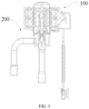
- the expansion valve 200 is mainly composed of a valve body (not shown) and an expansion valve coil structure 100.
- the expansion valve coil structure 100 includes a stator housing 10 and an electro-magnetic pole plate 20, and the stator housing 10 and the electromagnetic pole plate 20 are disposed opposite to each other.
- the stator housing 10 and the electromagnetic pole plate 20 are main components of the expansion valve coil structure 100.
- surfaces of materials used to form the stator housing 10 and the electromagnetic pole plate 20 have been coated with antirust coatings.
- an antirust layer 60 on a surface of raw materials is damaged, and there are many processed exposed surfaces such as incision and cut surface on the molded stator housing 10 and the electromagnetic pole plate 20.
- the stator housing 10 and the electromagnetic pole plate 20 are easy to rust and cannot effectively protect coil, which affects a service life and effect of the expansion valve 200.
- the stator housing 10 and the electromagnetic pole plate 20 are both provided with a plurality of processed exposed surfaces 50.
- a surface of the stator housing 10, a surface of the electromagnetic pole plate 20 and each of the plurality of processed exposed surfaces 50 are each covered with an antirust layer 60, respectively.
- the stator housing 10 and the electromagnetic pole plate 20 after processing and molding are rusted.
- the antirust layer 60 is covered on the processed exposed surface 50 on the stator housing 10 and the electromagnetic pole plate 20 to achieve comprehensive rust protection. It can effectively improve an antirust ability of the stator housing 10 and an antirust ability of the electromagnetic pole plate 20, thereby enhancing an antirust ability of the expansion valve coil structure 200 and prolonging a service life of the expansion valve coil structure 100.
- a plurality of first claw electrodes 11 are formed on the stator housing 10, and the plurality of first claw electrodes 11 are distributed at intervals along a circumferential direction of the stator housing 10.
- a plurality of second claw electrodes 21 are correspondingly processed on the electromagnetic pole plate 20, the plurality of second claw electrodes 21 are distributed at intervals along a circumferential direction of the electromagnetic pole plate 20.
- the plurality of first claw electrodes 11 and the plurality of second claw electrodes 21 are arranged opposite to each other and inserted in an alternating configuration in intervals to enclose and form an internal hole 40 of the expansion valve coil structure 200.
- the processed exposed surface 50 includes surfaces of the plurality of first claw electrodes 11 and surfaces of the plurality of second claw electrodes 21.
- the plurality of first claw electrodes 11 and the plurality of second claw electrodes 21 are processed and formed on the stator housing 10 and the electromagnetic pole plate 20, respectively, which leads to a destruction of the antirust layer 60 in the raw materials, and additional incisions or cut surfaces are generated during processing.
- the antirust layer 60 By coating the antirust layer 60 on the cut surfaces and/or incisions formed after the processing of the plurality of first claw electrodes 11 and the plurality of second claw electrode 21, the antirust ability of the plurality of first claw electrodes 11 and the plurality of second claw electrodes 21 can be effectively improved.
- the expansion valve coil structure 100 further includes a coil framework 30, and a coil 70 is wound around the coil framework 30 to form a coil winding.
- the coil winding is located between the stator housing 10 and the electromagnetic pole plate 20, and the plurality of first claw electrodes 11 and the plurality of second claw electrodes 21 are located in the coil winding. Such that the coiled coil 70 is enclosed outside the internal hole 40 of the expansion valve coil structure 100.
- the stator housing 10 is provided with a plurality of first positioning holes 14, and positioning protrusions of the coil framework 30 extend into the plurality of first positioning holes 14 to realize a positioning between the coil framework 30 and the stator housing 10.
- the antirust layer 60 is further disposed on a hole wall of each of the first positioning holes 14, that is, the processed exposed surface 50 includes a hole wall surface of the first positioning hole 14. In this way, the stator housing 10 can be protected from details, and a joint between the stator housing 10 and the coil framework 30 can be prevented from rusting, which will affect a connection stability and a service life of the stator housing 10 and a connection stability and a service life of the coil framework 30.
- a circumferential side wall of the stator housing 10 is provided with an avoidance port 12, and when assembled, the stator housing 10 covers the coil framework 30 and the electromagnetic pole plate 20.
- the avoidance port 12 is configured for parts of the coil framework 30 protruding from the stator housing 10 to pass through, such as the plug wire portion 31 protruding from the coil framework 30 and the ear part 22 protruding from the electromagnetic pole plate 20.
- the antirust layer 60 is further disposed on each surface of the avoidance port 12, that is, the processed exposed surface 50 includes the machined surface of the avoidance port 12, thereby preventing the local position of the stator housing 10 from rusting and enhancing the antirust ability of the stator housing 10.
- the electromagnetic pole plate 20 is provided with a plurality of second positioning holes 23 and a plurality of third positioning holes 24, A hole wall of each of the plurality of second positioning holes 23 and a hole wall of each of the plurality of third positioning holes 24 are covered with the antirust layer 60, that is, the processed exposed surface 50 includes wall surfaces of the plurality of second positioning holes 23 and wall surfaces of the plurality of third positioning holes 24.
- the expansion valve coil structure 100 includes two coil frameworks 30, and two the electromagnetic pole plates 20 are located between the two coil frameworks 30.
- the plurality of second claw electrodes 21 of two of the electromagnetic pole plate 20 are arranged back-to-back.
- the plurality of second positioning holes 23 are configured to cooperate with the positioning protrusions on the adjacent electromagnetic pole plates 20 to realize mutual positioning between the electromagnetic pole plates 20.
- the plurality of third positioning holes 24 are configured for matching of positioning protrusions on the coil framework 30 to realize the mutual positioning between them, so that the two corresponding coil frameworks 30 are relatively fixed and a displacement of the coil framework 30 and the electromagnetic pole plate 20 is prevented.
- the plurality of second positioning holes 23 and the plurality of third positioning holes 24 are alternately arranged at intervals, so that the positioning positions are evenly distributed and positioning is more stable.
- the plurality of second positioning holes 23 and the plurality of third positioning holes 24 are arranged along a circumferential direction of the electromagnetic pole plate 20, so as to ensure that all directions of the electromagnetic pole plate 20 can be fixed and prevent the electromagnetic pole plate 20 from shifting.
- the antirust layer 60 is disposed on the surface of the stator housing 10, the surface of the electromagnetic pole plate 20 and each of the plurality of processed exposed surfaces 50 by a plating process or a coating process.
- the plating process or the coating process is simple, and each surface can be evenly covered with the antirust layer 60, especially for hidden positions such as hole walls and bending corners. This process can effectively coat hidden positions.
- a processing mode of the antirust layer 60 is not limited to the above.
- a thickness of the antirust layer 60 is in a range of 2 ⁇ m to 30 ⁇ m.
- the thickness of the antirust layer 60 is less than 2 ⁇ m, a surface coating is damaged and loses the antirust function in a production process, while when the thickness of the antirust layer 60 is more than 30 ⁇ m, the thickness of the antirust layer 60 is too thick, which is easy to cause the antirust layer 60 to blister and fall off and lose the antirust function. Therefore, the thickness of the antirust layer 60 is in the range of 2 ⁇ m to 30 ⁇ m in the present application, and within this range, the antirust layer 60 has little influence on magnetic conductivity performance of the electromagnetic pole plate 20.
- the thickness of the antirust layer 60 is not limited to the above thickness, and the thickness of the antirust layer 60 can also be determined according to an actual application.
- the thickness of the antirust layer 60 is in a range of 8 ⁇ m to 16 ⁇ m. With this arrangement, the influence of the antirust layer 60 on the magnetic conductivity energy of the electromagnetic pole plate 20 can be ignored.
- the antirust layer 60 can be zinc plating, nickel plating, tin plating, chromium plating, etc. Of course, it can also be other anti-rust materials, such as alloy plating.
- the specific material of the antirust layer 60 can be selected according to the application environment, for example, in the organic acid environment, the antirust layer can be selected as tin coating.
- the antirust layer 60 can be provided with one or more layers, and the materials of each layer can be the same or different, for example, the surface of the stator housing 10 is plated with zinc coating first, and then with chromium coating with higher hardness.
- the stator housing 10 and the electromagnetic pole plate 20 are made of non-austenitic stainless steel.
- This design can further improve a corrosion resistance of the product without affecting the magnetic permeability of the product.
- Non-austenitic stainless steel has good strength properties, which makes the plurality of first claw electrodes 11 and the plurality of second claw electrodes 21 difficult to deform, and it can avoid an influence of claw electrode deformation on an actuation performance.
- the thickness of the claw electrode can be further reduced, which is beneficial to a miniaturization of the expansion valve 200.
Landscapes
- Engineering & Computer Science (AREA)
- General Engineering & Computer Science (AREA)
- Physics & Mathematics (AREA)
- Mechanical Engineering (AREA)
- Electromagnetism (AREA)
- Thermal Sciences (AREA)
- Power Engineering (AREA)
- Electromagnets (AREA)
- Magnetically Actuated Valves (AREA)
- Other Surface Treatments For Metallic Materials (AREA)
- Motor Or Generator Frames (AREA)
- Connection Of Motors, Electrical Generators, Mechanical Devices, And The Like (AREA)
- Electrically Driven Valve-Operating Means (AREA)
- Laminated Bodies (AREA)
Abstract
Description
- This application claims priority to
Chinese patent application No. 202122989503.4, filed on November 30, 2021 - The present application relates to the field of electromagnetic valve technology, and in particular, to an expansion valve coil structure and an expansion valve.
- In the related art, materials used for processing an expansion valve coil structure are usually coated with antirust materials. After the corresponding materials are processed to form a stator housing and an electromagnetic pole plate, an antirust layer on material surfaces of the stator housing and the electrode plate may be destroyed, and there were a plurality of exposed surfaces formed by processing, which greatly weakened an antirust ability of the formed expansion valve coil structure.
- According to various embodiments of the present application, an expansion valve coil structure and an expansion valve are provided with enhanced antirust ability and comprehensive antirust.
- The present application provides an expansion valve coil structure. The expansion valve coil structure includes a stator housing and an electromagnetic pole plate. The stator housing and the electromagnetic pole plate are disposed opposite to each other. The stator housing and the electromagnetic pole plate are both provided with a plurality of processed exposed surfaces. A surface of the stator housing, a surface of the electromagnetic pole plate and each of the plurality of processed exposed surfaces are each covered with an antirust layer, respectively.
- With this arrangement, it can be ensured that each processed exposed surface of the stator housing and each processed exposed surface of the electromagnetic pole plate are covered with the antirust layer. It can effectively improve an antirust ability of the stator housing and an antirust ability of the electromagnetic pole plate, thereby enhancing an antirust ability of the expansion valve coil structure and prolonging a service life of the expansion valve coil structure.
- In some embodiments, a thickness of the antirust layer is in a range of 2 µm to 30 µm.
- Within this thickness range, the antirust layer has little influence on a magnetic conductivity energy of the electromagnetic pole plate, and an antirust effect of the electromagnetic pole plate is greater. Considering magnetic conductivity energy, antirust effect and processing technology, the thickness of the antirust layer can be 2 µm -30 µm. In this way, a requirement for machining accuracy is low, and a machining difficulty is reduced.
- In some embodiments, the thickness of the antirust layer is in a range of 8 µm to 16 µm.
- With this arrangement, the influence of the antirust layer on the magnetic conductivity energy of the electromagnetic pole plate can be ignored.
- In some embodiments, the antirust layer is disposed on the surface of the stator housing, the surface of the electromagnetic pole plate and each of the plurality of processed exposed surfaces by plating or coating.
- The antirust layer is added to each surface by plating or coating, the plating or coating process is simple, and each surface can be evenly covered with the antirust layer, especially for hidden positions such as hole walls and bending corners. This process can effectively coat hidden positions.
- In some embodiments, a plurality of first claw electrodes are formed on the stator housing, and the plurality of first claw electrodes are distributed at intervals along a circumferential direction of the stator housing; a plurality of second claw electrodes are correspondingly processed on the electromagnetic pole plate, the plurality of second claw electrodes are distributed at intervals along a circumferential direction of the electromagnetic pole plate, the plurality of first claw electrodes and the plurality of second claw electrodes are arranged opposite to each other and inserted in an alternating configuration in intervals to enclose and form an internal hole of the expansion valve coil structure.
- In some embodiments, the plurality of processed exposed surfaces comprises surfaces of the plurality of first claw electrodes and surfaces of the plurality of second claw electrodes.
- With this arrangement, an antirust property of the plurality of first claw electrodes and an antirust property of the plurality of second claw electrodes are effectively enhanced.
- In some embodiments, the stator housing is provided with a plurality of first positioning holes, and the antirust layer is further disposed on a hole wall of each of the plurality of first positioning holes.
- In some embodiments, a circumferential side wall of the stator housing is provided with an avoidance port, and the antirust layer is further disposed on each surface of the avoidance port.
- In some embodiments, the electromagnetic pole plate is provided with a plurality of second positioning holes and a plurality of third positioning holes, and the antirust layer is further disposed on a hole wall of each of the plurality of second positioning holes and a hole wall of each of the plurality of third positioning holes, respectively.
- The present application further provides an expansion valve including the above expansion valve coil structure is provided.
- Details of one or more embodiments of this application are presented in the attached drawings and descriptions below. And other features, purposes and advantages of this application will become apparent from the description, drawings and claims.
- For a better description and illustration of embodiments and/or examples of those disclosures disclosed herein, reference may be made to one or more attached drawings. Additional details or examples used to describe the drawings should not be considered as limiting the scope of any of the disclosed disclosures, currently described embodiments and/or examples, and currently understood best modes of these disclosures.
-
FIG. 1 is a schematic view of a stator housing in an embodiment of the present application. -
FIG. 2 is a schematic view of an electromagnetic pole plate in an embodiment of the present application. -
FIG. 3 is a sectional view of an expansion valve coil structure in an embodiment of the present application. -
FIG. 4 is a schematic view of an expansion valve in an embodiment of the present application. -
FIG. 5 is a sectional view of an expansion valve in an embodiment of the present application. - Reference signs are as follows: 100 represents an expansion valve coil structure; 10 represents a stator housing; 11 represents a first claw electrode; 12 represents an avoidance port; 14 represents a first positioning hole; 20 represents an electromagnetic pole plate; 21 represents a second claw electrode; 22 represents an ear portion; 23 represents a second positioning hole; 24 represents a third positioning hole; 30 represents a coil framework; 31 represents a plug wire portion; 40 represents an internal hole; 50 represents a processed exposed surface; 60 represents an antirust layer; and 70 represents a coil; and 200 represents an expansion valve.
- The technical scheme in the embodiment of this application will be described clearly and completely with the attached drawings. Obviously, the described embodiment is only a part of the embodiment of this application, not the whole embodiment. Based on the embodiments in this application, all other embodiments obtained by ordinary technicians in this field without creative work belong to the protection scope of this application.
- It should be noted that when a component is considered to be "mounted" on another component, it can be directly on the other component or there can be a component in the middle. When a component is considered to be "set on" another component, it can be directly set on another component or there may be intervening components at the same time. When a component is considered to be "fixed" to another component, it can be directly fixed to another component or there may be intervening components at the same time.
- Unless otherwise defined, all technical and scientific terms used herein have the same meaning as commonly understood by those skilled in the technical field of this application. The terminology used herein in the specification of this application is only for the purpose of describing specific embodiments, and is not intended to limit this application. As used herein, the term "or/and" includes any and all combinations of one or more related listed items.
- Referring to
FIG. 3 to FIG. 5 , the present application provides anexpansion valve 200. Theexpansion valve 200 is mainly composed of a valve body (not shown) and an expansionvalve coil structure 100. The expansionvalve coil structure 100 includes astator housing 10 and an electro-magnetic pole plate 20, and thestator housing 10 and theelectromagnetic pole plate 20 are disposed opposite to each other. - The
stator housing 10 and theelectromagnetic pole plate 20 are main components of the expansionvalve coil structure 100. However, in the related art, before processing, surfaces of materials used to form thestator housing 10 and theelectromagnetic pole plate 20 have been coated with antirust coatings. After processing and molding, anantirust layer 60 on a surface of raw materials is damaged, and there are many processed exposed surfaces such as incision and cut surface on the moldedstator housing 10 and theelectromagnetic pole plate 20. Without theantirust layer 60 on each of the processed exposedsurface 50, the stator housing 10 and theelectromagnetic pole plate 20 are easy to rust and cannot effectively protect coil, which affects a service life and effect of theexpansion valve 200. - Referring to
FIG. 1 and FIG. 2 , the stator housing 10 and theelectromagnetic pole plate 20 are both provided with a plurality of processed exposedsurfaces 50. A surface of the stator housing 10, a surface of theelectromagnetic pole plate 20 and each of the plurality of processed exposedsurfaces 50 are each covered with anantirust layer 60, respectively. - In the present application, the stator housing 10 and the
electromagnetic pole plate 20 after processing and molding are rusted. Theantirust layer 60 is covered on the processed exposedsurface 50 on thestator housing 10 and theelectromagnetic pole plate 20 to achieve comprehensive rust protection. It can effectively improve an antirust ability of thestator housing 10 and an antirust ability of theelectromagnetic pole plate 20, thereby enhancing an antirust ability of the expansionvalve coil structure 200 and prolonging a service life of the expansionvalve coil structure 100. - Referring to
FIG. 1 and FIG. 2 , a plurality offirst claw electrodes 11 are formed on thestator housing 10, and the plurality offirst claw electrodes 11 are distributed at intervals along a circumferential direction of thestator housing 10. A plurality ofsecond claw electrodes 21 are correspondingly processed on theelectromagnetic pole plate 20, the plurality ofsecond claw electrodes 21 are distributed at intervals along a circumferential direction of theelectromagnetic pole plate 20. The plurality offirst claw electrodes 11 and the plurality ofsecond claw electrodes 21 are arranged opposite to each other and inserted in an alternating configuration in intervals to enclose and form aninternal hole 40 of the expansionvalve coil structure 200. - In an embodiment, the processed exposed
surface 50 includes surfaces of the plurality offirst claw electrodes 11 and surfaces of the plurality ofsecond claw electrodes 21. The plurality offirst claw electrodes 11 and the plurality ofsecond claw electrodes 21 are processed and formed on thestator housing 10 and theelectromagnetic pole plate 20, respectively, which leads to a destruction of theantirust layer 60 in the raw materials, and additional incisions or cut surfaces are generated during processing. By coating theantirust layer 60 on the cut surfaces and/or incisions formed after the processing of the plurality offirst claw electrodes 11 and the plurality ofsecond claw electrode 21, the antirust ability of the plurality offirst claw electrodes 11 and the plurality ofsecond claw electrodes 21 can be effectively improved. - The expansion
valve coil structure 100 further includes acoil framework 30, and acoil 70 is wound around thecoil framework 30 to form a coil winding. The coil winding is located between thestator housing 10 and theelectromagnetic pole plate 20, and the plurality offirst claw electrodes 11 and the plurality ofsecond claw electrodes 21 are located in the coil winding. Such that the coiledcoil 70 is enclosed outside theinternal hole 40 of the expansionvalve coil structure 100. - Referring to
FIG. 1 , thestator housing 10 is provided with a plurality of first positioning holes 14, and positioning protrusions of thecoil framework 30 extend into the plurality of first positioning holes 14 to realize a positioning between thecoil framework 30 and thestator housing 10. In some embodiments, theantirust layer 60 is further disposed on a hole wall of each of the first positioning holes 14, that is, the processed exposedsurface 50 includes a hole wall surface of thefirst positioning hole 14. In this way, thestator housing 10 can be protected from details, and a joint between thestator housing 10 and thecoil framework 30 can be prevented from rusting, which will affect a connection stability and a service life of thestator housing 10 and a connection stability and a service life of thecoil framework 30. - Referring to
FIG. 1 andFIG. 3 , a circumferential side wall of thestator housing 10 is provided with anavoidance port 12, and when assembled, thestator housing 10 covers thecoil framework 30 and theelectromagnetic pole plate 20. Theavoidance port 12 is configured for parts of thecoil framework 30 protruding from thestator housing 10 to pass through, such as theplug wire portion 31 protruding from thecoil framework 30 and theear part 22 protruding from theelectromagnetic pole plate 20. In addition, theantirust layer 60 is further disposed on each surface of theavoidance port 12, that is, the processed exposedsurface 50 includes the machined surface of theavoidance port 12, thereby preventing the local position of thestator housing 10 from rusting and enhancing the antirust ability of thestator housing 10. - Referring to
FIG. 2 andFIG. 3 , theelectromagnetic pole plate 20 is provided with a plurality of second positioning holes 23 and a plurality of third positioning holes 24, A hole wall of each of the plurality of second positioning holes 23 and a hole wall of each of the plurality of third positioning holes 24 are covered with theantirust layer 60, that is, the processed exposedsurface 50 includes wall surfaces of the plurality of second positioning holes 23 and wall surfaces of the plurality of third positioning holes 24. The expansionvalve coil structure 100 includes twocoil frameworks 30, and two theelectromagnetic pole plates 20 are located between the twocoil frameworks 30. The plurality ofsecond claw electrodes 21 of two of theelectromagnetic pole plate 20 are arranged back-to-back. The plurality of second positioning holes 23 are configured to cooperate with the positioning protrusions on the adjacentelectromagnetic pole plates 20 to realize mutual positioning between theelectromagnetic pole plates 20. The plurality of third positioning holes 24 are configured for matching of positioning protrusions on thecoil framework 30 to realize the mutual positioning between them, so that the twocorresponding coil frameworks 30 are relatively fixed and a displacement of thecoil framework 30 and theelectromagnetic pole plate 20 is prevented. - In an embodiment, the plurality of second positioning holes 23 and the plurality of third positioning holes 24 are alternately arranged at intervals, so that the positioning positions are evenly distributed and positioning is more stable.
- In an embodiment, the plurality of second positioning holes 23 and the plurality of third positioning holes 24 are arranged along a circumferential direction of the
electromagnetic pole plate 20, so as to ensure that all directions of theelectromagnetic pole plate 20 can be fixed and prevent theelectromagnetic pole plate 20 from shifting. - In an embodiment, the
antirust layer 60 is disposed on the surface of thestator housing 10, the surface of theelectromagnetic pole plate 20 and each of the plurality of processed exposedsurfaces 50 by a plating process or a coating process. The plating process or the coating process is simple, and each surface can be evenly covered with theantirust layer 60, especially for hidden positions such as hole walls and bending corners. This process can effectively coat hidden positions. In other embodiments, a processing mode of theantirust layer 60 is not limited to the above. - In an embodiment, a thickness of the
antirust layer 60 is in a range of 2 µm to 30 µm. When the thickness of theantirust layer 60 is less than 2 µm, a surface coating is damaged and loses the antirust function in a production process, while when the thickness of theantirust layer 60 is more than 30 µm, the thickness of theantirust layer 60 is too thick, which is easy to cause theantirust layer 60 to blister and fall off and lose the antirust function. Therefore, the thickness of theantirust layer 60 is in the range of 2 µm to 30 µm in the present application, and within this range, theantirust layer 60 has little influence on magnetic conductivity performance of theelectromagnetic pole plate 20. The thicker theantirust layer 60, the lower the requirements for coating or electroplating of theantirust layer 60 are, thus reducing a processing cost of products. In other embodiments, the thickness of theantirust layer 60 is not limited to the above thickness, and the thickness of theantirust layer 60 can also be determined according to an actual application. - In an embodiment, the thickness of the
antirust layer 60 is in a range of 8 µm to 16 µm. With this arrangement, the influence of theantirust layer 60 on the magnetic conductivity energy of theelectromagnetic pole plate 20 can be ignored. - Furthermore, the
antirust layer 60 can be zinc plating, nickel plating, tin plating, chromium plating, etc. Of course, it can also be other anti-rust materials, such as alloy plating. The specific material of theantirust layer 60 can be selected according to the application environment, for example, in the organic acid environment, the antirust layer can be selected as tin coating. When electrochemical corrosion occurs, a plating metal at an anode is continuously lost to protect a base metal, and then thestator housing 10 and theelectromagnetic pole plate 20 are electrochemically protected. - In an embodiment, the
antirust layer 60 can be provided with one or more layers, and the materials of each layer can be the same or different, for example, the surface of thestator housing 10 is plated with zinc coating first, and then with chromium coating with higher hardness. - In an embodiment, the
stator housing 10 and theelectromagnetic pole plate 20 are made of non-austenitic stainless steel. This design can further improve a corrosion resistance of the product without affecting the magnetic permeability of the product. Non-austenitic stainless steel has good strength properties, which makes the plurality offirst claw electrodes 11 and the plurality ofsecond claw electrodes 21 difficult to deform, and it can avoid an influence of claw electrode deformation on an actuation performance. In addition, the thickness of the claw electrode can be further reduced, which is beneficial to a miniaturization of theexpansion valve 200. - In addition, it should be noted that the words "first" and "second" are used to define parts only for a convenience of distinguishing corresponding parts. Unless otherwise stated, the above words have no special meaning, so they cannot be understood as limiting a protection scope of the present invention.
- The technical features of the above-mentioned embodiments can be combined arbitrarily. In order to make the description concise, not all possible combinations of the technical features are described in the embodiments. However, as long as there is no contradiction in the combination of these technical features, the combinations should be considered as in the scope of the present application.
- One of ordinary skill in the art should recognize that the above embodiments are used only to illustrate the present application and are not used to limit the present application, and that appropriate variations and improvements to the above embodiments fall within the protection scope of the present application so long as they are made without departing from the substantial spirit of the present application.
Claims (10)
- An expansion valve coil structure, comprising a stator housing and an electromagnetic pole plate, wherein the stator housing and the electromagnetic pole plate are disposed opposite to each other;
characterized in that the stator housing and the electromagnetic pole plate are both provided with a plurality of processed exposed surfaces; a surface of the stator housing, a surface of the electromagnetic pole plate and each of the plurality of processed exposed surfaces are each covered with an antirust layer, respectively. - The expansion valve coil structure of claim 1, wherein a thickness of the antirust layer is in a range of 2 µm to 30 µm.
- The expansion valve coil structure of claim 2, wherein the thickness of the antirust layer is in a range of 8 µm to 16 µm.
- The expansion valve coil structure of claim 1, wherein the antirust layer is disposed on the surface of the stator housing, the surface of the electromagnetic pole plate and each of the plurality of processed exposed surfaces by plating or coating.
- The expansion valve coil structure of claim 1, wherein a plurality of first claw electrodes are formed on the stator housing, and the plurality of first claw electrodes are distributed at intervals along a circumferential direction of the stator housing; a plurality of second claw electrodes are correspondingly processed on the electromagnetic pole plate, the plurality of second claw electrodes are distributed at intervals along a circumferential direction of the electromagnetic pole plate, the plurality of first claw electrodes and the plurality of second claw electrodes are arranged opposite to each other and inserted in an alternating configuration in intervals to enclose and form an internal hole of the expansion valve coil structure.
- The expansion valve coil structure of claim 5, wherein the plurality of processed exposed surfaces comprises surfaces of the plurality of first claw electrodes and surfaces of the plurality of second claw electrodes.
- The expansion valve coil structure of claim 1, wherein the stator housing is provided with a plurality of first positioning holes, and the antirust layer is further disposed on a hole wall of each of the plurality of first positioning holes.
- The expansion valve coil structure of claim 1, wherein a circumferential side wall of the stator housing is provided with an avoidance port, and the antirust layer is further disposed on each surface of the avoidance port.
- The expansion valve coil structure of claim 1, wherein the electromagnetic pole plate is provided with a plurality of second positioning holes and a plurality of third positioning holes, and the antirust layer is further disposed on a hole wall of each of the plurality of second positioning holes and a hole wall of each of the plurality of third positioning holes, respectively.
- An expansion valve, characterized by comprising the expansion valve coil structure of any one of claims 1 to 9.
Applications Claiming Priority (2)
| Application Number | Priority Date | Filing Date | Title |
|---|---|---|---|
| CN202122989503.4U CN217463394U (en) | 2021-11-30 | 2021-11-30 | Expansion valve coil structure and expansion valve |
| PCT/CN2022/134248 WO2023098577A1 (en) | 2021-11-30 | 2022-11-25 | Expansion valve coil structure and expansion valve |
Publications (2)
| Publication Number | Publication Date |
|---|---|
| EP4421414A1 true EP4421414A1 (en) | 2024-08-28 |
| EP4421414A4 EP4421414A4 (en) | 2025-03-05 |
Family
ID=83234650
Family Applications (1)
| Application Number | Title | Priority Date | Filing Date |
|---|---|---|---|
| EP22900382.7A Pending EP4421414A4 (en) | 2021-11-30 | 2022-11-25 | EXPANSION VALVE COIL STRUCTURE AND ASSOCIATED EXPANSION VALVE |
Country Status (6)
| Country | Link |
|---|---|
| US (1) | US20240309962A1 (en) |
| EP (1) | EP4421414A4 (en) |
| JP (1) | JP2024544125A (en) |
| KR (1) | KR20240091248A (en) |
| CN (1) | CN217463394U (en) |
| WO (1) | WO2023098577A1 (en) |
Families Citing this family (1)
| Publication number | Priority date | Publication date | Assignee | Title |
|---|---|---|---|---|
| CN217463394U (en) * | 2021-11-30 | 2022-09-20 | 浙江盾安人工环境股份有限公司 | Expansion valve coil structure and expansion valve |
Family Cites Families (10)
| Publication number | Priority date | Publication date | Assignee | Title |
|---|---|---|---|---|
| JP3060358B2 (en) * | 1994-06-24 | 2000-07-10 | 富士電気化学株式会社 | Method of manufacturing stator yoke and stator yoke |
| JP3415281B2 (en) * | 1994-08-18 | 2003-06-09 | 株式会社不二工機 | Electric flow control valve |
| JP3877478B2 (en) * | 1999-11-29 | 2007-02-07 | 日本電産サンキョー株式会社 | Valve drive device |
| CN101777408A (en) * | 2009-01-08 | 2010-07-14 | 浙江三花股份有限公司 | Processing method of coil device for solenoid valve |
| CN102758947A (en) * | 2011-04-27 | 2012-10-31 | 浙江三花股份有限公司 | Electronic expansion valve and coil thereof |
| CN205816124U (en) * | 2016-07-08 | 2016-12-21 | Bac大连有限公司 | Movable anti-corrosion painting work frame for evaporative heat exchange equipment |
| CN108533807B (en) * | 2017-03-02 | 2021-01-22 | 浙江三花制冷集团有限公司 | Flow regulating valve, power head component thereof and assembling method of flow regulating valve |
| CN111434403B (en) * | 2019-04-30 | 2021-12-21 | 苏州普热斯勒先进成型技术有限公司 | Method and device for manufacturing corrosion-resistant hot stamping part |
| CN214626535U (en) * | 2021-02-01 | 2021-11-05 | 浙江盾安人工环境股份有限公司 | Electromagnetic coil device and electronic expansion valve having the same |
| CN217463394U (en) * | 2021-11-30 | 2022-09-20 | 浙江盾安人工环境股份有限公司 | Expansion valve coil structure and expansion valve |
-
2021
- 2021-11-30 CN CN202122989503.4U patent/CN217463394U/en active Active
-
2022
- 2022-11-25 EP EP22900382.7A patent/EP4421414A4/en active Pending
- 2022-11-25 WO PCT/CN2022/134248 patent/WO2023098577A1/en not_active Ceased
- 2022-11-25 JP JP2024525994A patent/JP2024544125A/en active Pending
- 2022-11-25 KR KR1020247018165A patent/KR20240091248A/en active Pending
-
2024
- 2024-05-29 US US18/676,655 patent/US20240309962A1/en active Pending
Also Published As
| Publication number | Publication date |
|---|---|
| EP4421414A4 (en) | 2025-03-05 |
| JP2024544125A (en) | 2024-11-28 |
| CN217463394U (en) | 2022-09-20 |
| WO2023098577A1 (en) | 2023-06-08 |
| KR20240091248A (en) | 2024-06-21 |
| US20240309962A1 (en) | 2024-09-19 |
Similar Documents
| Publication | Publication Date | Title |
|---|---|---|
| US20240309962A1 (en) | Expansion valve coil structure and preparing method thereof, and expansion valve | |
| EP0504994B1 (en) | Rotor of a canned motor for a canned motor pump | |
| WO2013054941A2 (en) | Mating-type connection terminal, and manufacturing method therefor | |
| EP3745487B1 (en) | Secondary battery | |
| KR20170053888A (en) | Electrolytic Copper Foil, Electrode Comprising The Same, Secondary Battery Comprising The Same, and Method for Manufacturing The Same | |
| EP3726603B1 (en) | Method of manufacturing a secondary battery | |
| US5397658A (en) | Edge coated anode current collector cells and methods | |
| KR20230148807A (en) | Steel foil for battery containers and pouch-type battery containers manufactured therefrom | |
| US11489223B2 (en) | Secondary battery | |
| US10164350B2 (en) | Terminal attached wire | |
| EP4607567A1 (en) | Iron core and contactor | |
| CN214064553U (en) | Corrosion-resistant and oxidation-resistant cold-rolled strip steel | |
| WO2024022971A3 (en) | Housing for an electronic element, preferably a battery cell or a capacitor | |
| CN223390642U (en) | Battery and housing thereof | |
| CN219965484U (en) | Novel heavy anti-corrosion coating with strong acid resistance and high impact resistance | |
| US20070092751A1 (en) | Plate for housing and/or lids for button cells and process for manufacturing such a plate | |
| CN112219250B (en) | Capacitor, assembly comprising a capacitor and a busbar, and method for manufacturing a capacitor | |
| CN216130105U (en) | Road and bridge engineering is with steel sheet pile that rust-resistant effect is good | |
| US20160268864A1 (en) | Motor | |
| KR20030053029A (en) | Galvanic Element Having a Thin, Flat, and Flexible Metallic Housing | |
| US12166323B2 (en) | Crimp terminal and terminal-attached wire | |
| KR102775114B1 (en) | Connector configured to connect or disconnect based on magnetic force | |
| CN221783370U (en) | Battery pack cover and battery pack case having the same | |
| US20240154338A1 (en) | Terminal and processing method therefor | |
| CN220420304U (en) | Antioxidant tin-plated soft round copper wire |
Legal Events
| Date | Code | Title | Description |
|---|---|---|---|
| STAA | Information on the status of an ep patent application or granted ep patent |
Free format text: STATUS: THE INTERNATIONAL PUBLICATION HAS BEEN MADE |
|
| PUAI | Public reference made under article 153(3) epc to a published international application that has entered the european phase |
Free format text: ORIGINAL CODE: 0009012 |
|
| STAA | Information on the status of an ep patent application or granted ep patent |
Free format text: STATUS: REQUEST FOR EXAMINATION WAS MADE |
|
| 17P | Request for examination filed |
Effective date: 20240524 |
|
| AK | Designated contracting states |
Kind code of ref document: A1 Designated state(s): AL AT BE BG CH CY CZ DE DK EE ES FI FR GB GR HR HU IE IS IT LI LT LU LV MC ME MK MT NL NO PL PT RO RS SE SI SK SM TR |
|
| A4 | Supplementary search report drawn up and despatched |
Effective date: 20250130 |
|
| DAV | Request for validation of the european patent (deleted) | ||
| DAX | Request for extension of the european patent (deleted) | ||
| RIC1 | Information provided on ipc code assigned before grant |
Ipc: H01F 27/23 20060101ALN20250124BHEP Ipc: H01F 7/08 20060101ALI20250124BHEP Ipc: F16K 31/06 20060101ALI20250124BHEP Ipc: F25B 41/345 20210101AFI20250124BHEP |