EP4421399A1 - Fresh air equipment control method and apparatus, fresh air equipment, and storage medium - Google Patents
Fresh air equipment control method and apparatus, fresh air equipment, and storage medium Download PDFInfo
- Publication number
- EP4421399A1 EP4421399A1 EP22897347.5A EP22897347A EP4421399A1 EP 4421399 A1 EP4421399 A1 EP 4421399A1 EP 22897347 A EP22897347 A EP 22897347A EP 4421399 A1 EP4421399 A1 EP 4421399A1
- Authority
- EP
- European Patent Office
- Prior art keywords
- heat exchange
- fresh air
- exchange system
- temperature
- target
- Prior art date
- Legal status (The legal status is an assumption and is not a legal conclusion. Google has not performed a legal analysis and makes no representation as to the accuracy of the status listed.)
- Granted
Links
Images



Classifications
-
- F—MECHANICAL ENGINEERING; LIGHTING; HEATING; WEAPONS; BLASTING
- F24—HEATING; RANGES; VENTILATING
- F24F—AIR-CONDITIONING; AIR-HUMIDIFICATION; VENTILATION; USE OF AIR CURRENTS FOR SCREENING
- F24F11/00—Control or safety arrangements
- F24F11/62—Control or safety arrangements characterised by the type of control or by internal processing, e.g. using fuzzy logic, adaptive control or estimation of values
- F24F11/63—Electronic processing
- F24F11/65—Electronic processing for selecting an operating mode
-
- F—MECHANICAL ENGINEERING; LIGHTING; HEATING; WEAPONS; BLASTING
- F24—HEATING; RANGES; VENTILATING
- F24F—AIR-CONDITIONING; AIR-HUMIDIFICATION; VENTILATION; USE OF AIR CURRENTS FOR SCREENING
- F24F11/00—Control or safety arrangements
- F24F11/62—Control or safety arrangements characterised by the type of control or by internal processing, e.g. using fuzzy logic, adaptive control or estimation of values
- F24F11/63—Electronic processing
- F24F11/64—Electronic processing using pre-stored data
-
- F—MECHANICAL ENGINEERING; LIGHTING; HEATING; WEAPONS; BLASTING
- F24—HEATING; RANGES; VENTILATING
- F24F—AIR-CONDITIONING; AIR-HUMIDIFICATION; VENTILATION; USE OF AIR CURRENTS FOR SCREENING
- F24F1/00—Room units for air-conditioning, e.g. separate or self-contained units or units receiving primary air from a central station
- F24F1/0007—Indoor units, e.g. fan coil units
- F24F1/0035—Indoor units, e.g. fan coil units characterised by introduction of outside air to the room
-
- F—MECHANICAL ENGINEERING; LIGHTING; HEATING; WEAPONS; BLASTING
- F24—HEATING; RANGES; VENTILATING
- F24F—AIR-CONDITIONING; AIR-HUMIDIFICATION; VENTILATION; USE OF AIR CURRENTS FOR SCREENING
- F24F1/00—Room units for air-conditioning, e.g. separate or self-contained units or units receiving primary air from a central station
- F24F1/0007—Indoor units, e.g. fan coil units
- F24F1/0059—Indoor units, e.g. fan coil units characterised by heat exchangers
- F24F1/0063—Indoor units, e.g. fan coil units characterised by heat exchangers by the mounting or arrangement of the heat exchangers
-
- F—MECHANICAL ENGINEERING; LIGHTING; HEATING; WEAPONS; BLASTING
- F24—HEATING; RANGES; VENTILATING
- F24F—AIR-CONDITIONING; AIR-HUMIDIFICATION; VENTILATION; USE OF AIR CURRENTS FOR SCREENING
- F24F1/00—Room units for air-conditioning, e.g. separate or self-contained units or units receiving primary air from a central station
- F24F1/0007—Indoor units, e.g. fan coil units
- F24F1/0083—Indoor units, e.g. fan coil units with dehumidification means
-
- F—MECHANICAL ENGINEERING; LIGHTING; HEATING; WEAPONS; BLASTING
- F24—HEATING; RANGES; VENTILATING
- F24F—AIR-CONDITIONING; AIR-HUMIDIFICATION; VENTILATION; USE OF AIR CURRENTS FOR SCREENING
- F24F1/00—Room units for air-conditioning, e.g. separate or self-contained units or units receiving primary air from a central station
- F24F1/0007—Indoor units, e.g. fan coil units
- F24F1/0087—Indoor units, e.g. fan coil units with humidification means
-
- F—MECHANICAL ENGINEERING; LIGHTING; HEATING; WEAPONS; BLASTING
- F24—HEATING; RANGES; VENTILATING
- F24F—AIR-CONDITIONING; AIR-HUMIDIFICATION; VENTILATION; USE OF AIR CURRENTS FOR SCREENING
- F24F11/00—Control or safety arrangements
- F24F11/0008—Control or safety arrangements for air-humidification
-
- F—MECHANICAL ENGINEERING; LIGHTING; HEATING; WEAPONS; BLASTING
- F24—HEATING; RANGES; VENTILATING
- F24F—AIR-CONDITIONING; AIR-HUMIDIFICATION; VENTILATION; USE OF AIR CURRENTS FOR SCREENING
- F24F11/00—Control or safety arrangements
- F24F11/70—Control systems characterised by their outputs; Constructional details thereof
- F24F11/72—Control systems characterised by their outputs; Constructional details thereof for controlling the supply of treated air, e.g. its pressure
-
- F—MECHANICAL ENGINEERING; LIGHTING; HEATING; WEAPONS; BLASTING
- F24—HEATING; RANGES; VENTILATING
- F24F—AIR-CONDITIONING; AIR-HUMIDIFICATION; VENTILATION; USE OF AIR CURRENTS FOR SCREENING
- F24F12/00—Use of energy recovery systems in air conditioning, ventilation or screening
- F24F12/001—Use of energy recovery systems in air conditioning, ventilation or screening with heat-exchange between supplied and exhausted air
- F24F12/002—Use of energy recovery systems in air conditioning, ventilation or screening with heat-exchange between supplied and exhausted air using an intermediate heat-transfer fluid
- F24F12/003—Use of energy recovery systems in air conditioning, ventilation or screening with heat-exchange between supplied and exhausted air using an intermediate heat-transfer fluid using a heat pump
-
- F—MECHANICAL ENGINEERING; LIGHTING; HEATING; WEAPONS; BLASTING
- F24—HEATING; RANGES; VENTILATING
- F24F—AIR-CONDITIONING; AIR-HUMIDIFICATION; VENTILATION; USE OF AIR CURRENTS FOR SCREENING
- F24F12/00—Use of energy recovery systems in air conditioning, ventilation or screening
- F24F12/001—Use of energy recovery systems in air conditioning, ventilation or screening with heat-exchange between supplied and exhausted air
- F24F12/006—Use of energy recovery systems in air conditioning, ventilation or screening with heat-exchange between supplied and exhausted air using an air-to-air heat exchanger
-
- F—MECHANICAL ENGINEERING; LIGHTING; HEATING; WEAPONS; BLASTING
- F24—HEATING; RANGES; VENTILATING
- F24F—AIR-CONDITIONING; AIR-HUMIDIFICATION; VENTILATION; USE OF AIR CURRENTS FOR SCREENING
- F24F3/00—Air-conditioning systems in which conditioned primary air is supplied from one or more central stations to distributing units in the rooms or spaces where it may receive secondary treatment; Apparatus specially designed for such systems
- F24F3/12—Air-conditioning systems in which conditioned primary air is supplied from one or more central stations to distributing units in the rooms or spaces where it may receive secondary treatment; Apparatus specially designed for such systems characterised by the treatment of the air otherwise than by heating and cooling
- F24F3/14—Air-conditioning systems in which conditioned primary air is supplied from one or more central stations to distributing units in the rooms or spaces where it may receive secondary treatment; Apparatus specially designed for such systems characterised by the treatment of the air otherwise than by heating and cooling by humidification; by dehumidification
-
- F—MECHANICAL ENGINEERING; LIGHTING; HEATING; WEAPONS; BLASTING
- F24—HEATING; RANGES; VENTILATING
- F24F—AIR-CONDITIONING; AIR-HUMIDIFICATION; VENTILATION; USE OF AIR CURRENTS FOR SCREENING
- F24F2110/00—Control inputs relating to air properties
- F24F2110/10—Temperature
-
- F—MECHANICAL ENGINEERING; LIGHTING; HEATING; WEAPONS; BLASTING
- F24—HEATING; RANGES; VENTILATING
- F24F—AIR-CONDITIONING; AIR-HUMIDIFICATION; VENTILATION; USE OF AIR CURRENTS FOR SCREENING
- F24F2110/00—Control inputs relating to air properties
- F24F2110/20—Humidity
Definitions
- the present application relates to the technical field of air treatment devices, and in particular to a method for controlling a fresh air device, an apparatus for controlling a fresh air device, a fresh air device and a storage medium.
- the main purpose of the present application is to provide a method for controlling a fresh air device, an apparatus for controlling a fresh air device, a fresh air device and a storage medium, which aim to solve the technical problems in the related art that the fresh air temperature adjustment capability is limited, and dehumidification and energy saving cannot be taken into consideration at the same time.
- the present application provides a method for controlling a fresh air device
- the fresh air device comprises a first heat exchange system configured for exchanging heat between a fresh air channel and outdoor environment, and a second heat exchange system configured for exchanging heat between the fresh air channel and an exhaust air channel;
- the fresh air device comprises a humidification apparatus provided in the fresh air channel; after the comparing the fresh air moisture content with the target moisture content, and obtaining the moisture content comparison result, the method comprises:
- the determining the target operation mode of the first heat exchange system and the target operation mode of the second heat exchange system according to the moisture content comparison result and the temperature comparison result comprises:
- the determining the target operation mode of the first heat exchange system and the target operation mode of the second heat exchange system according to the moisture content comparison result and the temperature comparison result comprises:
- the determining the target operation mode of the first heat exchange system and the target operation mode of the second heat exchange system according to the moisture content comparison result and the temperature comparison result comprises:
- the method further comprises:
- the fresh air device further comprises an exhaust fan provided in the exhaust air channel and a fresh air fan provided in the fresh air channel;
- the first heat exchange system comprises a first compressor, and the second heat exchange system comprises a second compressor; after the driving the fresh air device to operate according to the target operation mode of the first heat exchange system and the target operation mode of the second heat exchange system, the method further comprises:
- the fresh air device comprises a humidification apparatus provided in the fresh air channel; after the driving the fresh air device to operate according to the target operation mode of the first heat exchange system and the target operation mode of the second heat exchange system, the method further comprises:
- the obtaining the target temperature and the target moisture content comprises:
- an apparatus for controlling a fresh air device comprising:
- the present application further proposes a fresh air device, comprising: a first heat exchange system, a second heat exchange system, a memory, a processor, and a control program for the fresh air device stored in the memory and operable on the processor; and the first heat exchange system is configured for exchanging heat between a fresh air channel and external environment, and the second heat exchange system is configured for exchanging heat between the fresh air channel and an exhaust air channel; when the control program for the fresh air device is executed by the processor, the method for controlling the fresh air device as mentioned above is implemented.
- the fresh air device is provided with the fresh air channel and the exhaust air channel
- the first heat exchange system comprises a first compressor, a first four-way valve, a first heat exchanger, a first throttling element and a second heat exchanger connected in sequence
- the second heat exchange system comprises a second compressor, a second four-way valve, a fourth heat exchanger, a third throttling element and a fifth heat exchanger connected in sequence
- the first heat exchange system further comprises a second throttling element and a third heat exchanger, the second throttling element and the third heat exchanger are connected in sequence after the second heat exchanger, and the third heat exchanger is provided in the fresh air channel and is provided upstream of the second heat exchanger; and/or the second heat exchanger further comprises a fourth throttling element and a sixth heat exchanger, the third throttling element and the sixth heat exchanger are connected in sequence after the fifth heat exchanger, and the sixth heat exchanger is provided in the fresh air channel and is provided upstream of the second heat exchanger.
- an area of the second heat exchanger is less than or equal to 50% of an area of the first heat exchanger, and an area of the fifth heat exchanger is less than or equal to 150% of an area of the fourth heat exchanger.
- the present application further proposes a storage medium, and a control program for a fresh air device is stored on the storage medium; when the control program for the fresh air device is executed by a processor, the method for controlling the fresh air device as mentioned above is implemented
- the fresh air device is provided with a two-stage heat exchange system, a first heat exchange system is configured to realize heat exchange between the fresh air channel and the outdoor environment, a second heat exchange system is configured to realize heat exchange between the fresh air channel and the exhaust air channel.
- reference sign name reference sign name 1001 processor C1 ⁇ C2 first compressor to second compressor 1002 communication bus V1 ⁇ V2 first four-way valve to second four-way valve 1003 user interface H1 ⁇ H6 first heat exchanger to sixth heat exchanger 1004 network interface K1 ⁇ K4 first throttling element to fourth throttling element 1005 memory Y1 ⁇ Y3 first fan to third fan 10 fresh air channel 100 parameter acquisition module 20 exhaust air channel 200 parameter determination module 300 parameter comparison module 400 mode determination module 500 mode drive module J1 humidification apparatus
- FIG. 1 is a structural schematic view of a fresh air device of hardware operating environment according to an embodiment of the present application.
- the fresh air device may comprise: a processor 1001, such as a central processing unit (CPU), a communication bus 1002, an user interface 1003, a network interface 1004, a memory1005 and a fresh air device.
- the communication bus 1002 is configured to realize connection communication among these components.
- the user interface 1003 may comprise a display.
- the optional user interface 1003 may further comprise a standard wired interface or a wireless interface.
- the wired interface of the user interface 1003 may be a USB interface in the present application.
- the network interface 1004 may comprise a standard wired interface or a wireless interface (such as a Wireless-Fidelity (Wi-Fi) interface).
- Wi-Fi Wireless-Fidelity
- the memory 1005 can be a high-speed random access memory (RAM), or a stable memory (Non-volatile Memory, NVM), such as a disk memory.
- the memory 1005 may further be a storage device independent of the aforementioned processor 1001.
- the fresh air device is configured to extract air from the outdoor environment, process it, and then transmit the treated air to the indoor environment as fresh air.
- FIG. 1 does not constitute a limitation on the fresh air machine, and may comprise more or less components than shown in the figure, or combine certain components, or arrange different components.
- the memory 1005 identified as a computer storage medium may comprise an operating system, a network communication module, a user interface module, and a control program for a fresh air device.
- the network interface 1004 is mainly configured to connect to the backend server and perform data communication with the backend server.
- the user interface 1003 is mainly configured to connect to an user device.
- the fresh air machine calls the control program for the fresh air device stored in the memory 1005 by the processor 1001, and executes the method for controlling the fresh air device provided by the embodiment of the present application.
- FIG. 2 is a structural schematic view of a fresh air device according to an embodiment of the present application.
- proposing a fresh air device proposing a fresh air device, and executing a method for controlling a fresh air device based on the fresh air device.
- the fresh air device may be provided with a first heat exchange system and a second heat exchange system.
- the first heat exchange system may comprise a first compressor C1, a first four-way valve V1, a first heat exchanger H1, a first throttling element K1, a second heat exchanger H2, the second throttling element K2 and the third heat exchanger H3.
- the second heat exchange system may comprise a second compressor C2, a second four-way valve V2, a fourth heat exchanger H4, a third throttling element K3, a fifth heat exchanger H5, a fourth throttling element K4 and the sixth heat exchanger H6.
- the first throttling element K1, the second throttling element K2, the third throttling element K3, and the fourth throttling element K4 may be electronic expansion valves.
- the first heat exchange system and the second heat exchange system can further share a multi-cylinder compressor.
- the fresh air device comprises a compressor with two independent cylinders.
- the first cylinder in the compressor is connected to the first four-way valve V1, the first heat exchanger H1, the first throttling element K1, the second heat exchanger H2, the second throttling element K2 and the third heat exchanger H3, so as to form the first heat exchange system.
- the second cylinder in the compressor is connected to the second four-way valve V2, the fourth heat exchanger H4, the third throttling element K3, the fifth heat exchanger H5, the fourth throttling element K4 and the sixth heat exchanger H6, so as to form the second heat exchange system.
- the fresh air device is further provided with a fresh air channel 10 and an exhaust air channel 20.
- the fresh air channel 10 is configured to transport air from the outdoor environment to the indoor environment.
- the exhaust air channel 20 is configured to transport air from the indoor environment to the outdoor environment.
- first heat exchanger H1 in the first heat exchange system may be located in an outdoor environment
- second heat exchanger H2 and the third heat exchanger H3 may be located in the above-mentioned fresh air channel 10, which are configured to realize heat exchange between the fresh air channel 10 and the outdoor environment.
- the fourth heat exchanger H4 in the second heat exchange system may be located in the above-mentioned exhaust air channel 20
- the fifth heat exchanger H5 and the sixth heat exchanger H6 may be located in the above-mentioned fresh air channel 10, which are configured to realize heat exchange between the fresh air channel 10 and the exhaust air channel 20.
- the first heat exchange system further comprises a first fan Y1 corresponding to the first heat exchanger H1, the fan is configured to realize heat exchange between the refrigerant in the first heat exchanger H1 and the outdoor environment.
- the fresh air channel 10 is further provided with a second fan Y2.
- the second fan Y2 is configured to extract air from the outdoor environment to the fresh air channel 10.
- the exhaust air channel 20 is further provided with a third fan Y3.
- the third fan Y3 is configured to extract air from the indoor environment into the exhaust air channel 20.
- the humidification apparatus J1 is provided next to the second fan Y2 at the entrance of the fresh air channel 10, and is configured to adjust the fresh air humidity at the entrance of the fresh air inlet channel.
- the working principle of the above fresh air device is as follows.
- the second fan Y2 extracts fresh air from the outdoor environment.
- the fresh air undergoes humidity adjustment by the humidification apparatus J1, and sequentially passes through the fifth heat exchanger H5, the second heat exchanger H2, the sixth heat exchanger H6 and the third heat exchanger H3 for four heat exchanges, and then is transported to the indoor environment.
- the third fan Y3 extracts the exhaust air from the indoor environment, and the exhaust air undergoes a heat exchange by the fourth heat exchanger H4 and is then transported to the outdoor.
- the fresh air device can have nine operational requirements of heating-up, heating-up and humidification, heating-up and dehumidification, cooling, cooling and humidification, cooling and dehumidification, isothermal humidification, isothermal dehumidification and direct fresh air supply.
- the nine requirements combining and controlling the operation modes of the first heat exchange system and the operation modes of the second heat exchange system, and adjusting the operation states to achieve their respective effects, so as to cause the system operate automatically and efficiently, and achieve the room temperature and room humidity to reach the control target.
- Both the first heat exchange system and the second heat exchange system can have a refrigeration mode (one of the cooling mode, the dehumidification mode or the reheating mode) and a heating mode (or the heating-up mode).
- the fifth heat exchanger H5, the second heat exchanger H2, the sixth heat exchanger H6 and the third heat exchanger H3 all cool and/or dehumidify and/or reheat the fresh air and then deliver the fresh air to the indoor.
- the fifth heat exchanger H5, the second heat exchanger H2, the sixth heat exchanger H6 and the third heat exchanger H3 all heat the fresh air and then transport the fresh air indoors.
- the fresh air passes through the second heat exchanger H2 of the first heat exchange system, the third heat exchanger H3 of the first heat exchange system, the fifth heat exchanger H5 of the second heat exchange system and the sixth heat exchanger H6 of the second heat exchange system to perform four heat exchanges, and the exhaust air passes through the fourth heat exchanger H4 of the second heat exchange system to perform heat recovery.
- the first heat exchange system and the second heat exchange system are both provided with four-way valves to switch between refrigeration mode and heating mode, so that it can realize exhaust heat recovery in refrigeration mode and heating mode under all working conditions throughout the year. Since the heat recovery system of the fresh air machine is in the form of a heat pump, the heat recovery of the second heat exchange system in cooling mode is sensible heat recovery, and the heat recovery of the second heat exchange system in heating mode is full heat (sensible heat + latent heat) recovery.
- the fresh air machine is provided with a plurality of alternating heat exchangers in the first heat exchange system, the second heat exchange system and the fresh air heat exchange channel, so as to realize condensation heat recovery and reheat recovery respectively, and respectively improve the system subcooling degree of the first heat exchange system and the second heat exchange system.
- an area of the second heat exchanger is less than or equal to 50% of an area of the first heat exchanger
- an area of the fifth heat exchanger is less than or equal to 150% of an area of the fourth heat exchanger.
- the pressure ratio detection method can use the pressure sensor or the temperature sensor on the heat exchanger coil. Based on this system structure, aiming at the energy-saving requirement for automatic operation of fresh air throughout the year and four seasons, by switching the four-way valve and controlling the throttling element, a combination of dual-system refrigeration, heating, dehumidification and reheat cycle modes can be achieved.
- the fresh air device further may comprise more or less components than shown in FIG. 2 , or some components may be combined, or different components may be arranged.
- FIG. 3 is a structural schematic view of a fresh air device according to another embodiment of the present application.
- the device may comprise a first heat exchange system and a second heat exchange system.
- the first heat exchange system may comprise a first compressor C1, a first four-way valve V1, a first heat exchanger H1, a first throttling element K1 and a second heat exchanger H2.
- the second heat exchange system may comprise a second compressor C2, a second four-way valve V2, a fourth heat exchanger H4, a third throttling element K3 and a fifth heat exchanger H5.
- the first throttling element K1 and the second throttling element K2 may be electronic expansion valves.
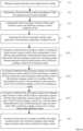
- FIG. 4 is a schematic flow chart of a method for controlling a fresh air device according to the first embodiment of the present application.
- the present application proposes the first embodiment of a method for controlling a fresh air device.
- the method for controlling the fresh air device can be applied to the above-mentioned fresh air device.
- the method for controlling the fresh air device comprises the following steps.
- Step S10 obtaining a target temperature and a target moisture content.
- the execution subject of this embodiment is the above-mentioned fresh air machine, which has functions such as data processing, data communication, and program operation.
- the operation of each component in the fresh air machine can be driven by a core controller. Therefore, the execution subject of this embodiment can further be the core controller in the fresh air machine.
- the core controller may be the above-mentioned processor. This embodiment takes the core controller as the execution subject for explanation.
- the target moisture content may be a moisture content determined based on the target temperature set by the user and the target humidity set by the user. Comparing the fresh air temperature with a preset fresh air temperature threshold value. In response to that the fresh air temperature is less than or equal to a minimum value of the preset fresh air temperature threshold value, taking a heating target temperature of a heating season (winter) as the target temperature. In response to that the fresh air temperature is within an interval of the preset fresh air temperature threshold value, taking a transition target temperature of a transition season as the target temperature. In response to that the fresh air temperature is greater than or equal to a maximum value of the preset fresh air temperature threshold value, taking a refrigeration target temperature in a refrigeration season (summer) as the target temperature.
- the target temperature can also be judged and determined according to the fresh air temperature and the preset fresh air temperature threshold value.
- the range of the preset fresh air temperature threshold value can be between 10 °C and 30 °C, or can be a single value or an interval value.
- the temperature threshold value is not limited.
- FIG. 5 can be referred, which is a schematic view that a fresh air device automatically operates a target temperature acquisition. By detecting the fresh air temperature Tw, comparing the fresh air temperature Tw with the fresh air temperature preset threshold value Twy, and determining the value range of the target temperature according to the temperature comparison result.
- the value range of the target temperature T 1 is 18 °C to 24 °C.
- the value range of the target temperature T 1 is preferably 20 °C to 26 °C.
- the value range of the target temperature T 1 is 24 °C to 28 °C.
- the target temperature may be based on the temperature value set by the user by a remote control device connected to the fresh air machine.
- the temperature value can be a single value or an interval value.
- the target temperature can be 19 °C or 19 °C to 25 °C. This embodiment does not place specific restrictions on the temperature value.
- the target humidity may also be the humidity determined according to the target temperature set by the user.
- the target humidity can be determined by searching the preset temperature and humidity mapping table by the target temperature.
- P air pressure (Pa); Ps represents water vapor partial pressure (Pa); ⁇ represents relative humidity (%); d accurately reflects the amount of water vapor contained in the air.
- the target moisture content can be a user-set value, or a preset certain value or certain range.
- Humidity can affect temperature, and temperature can change humidity. Humidity is also different at different temperatures. Therefore, when calculating the target moisture content, it is necessary to determine the temperature and humidity, and then determine the target moisture content. For example, when the fresh air temperature Tx is 30 °C and the fresh air moisture content is 20 g/kg, and it is judged to be summer. At this time, the target temperature T 1 is set to 24 °C to 26 °C, and the target moisture content d1 is set to 10 g/kg ⁇ 12 g/kg.
- Step S20 determining a fresh air moisture content according to a fresh air temperature and a fresh air humidity.
- a temperature sensor is provided in front of the entrance of the fresh air inlet channel or the heat exchanger of the fresh air inlet channel, and the temperature sensor is connected to the core controller.
- the temperature sensor is able to feedback a detection signal to the core controller in real time or intermittently, and the detection signal is configured to characterize the temperature of the environment where the temperature sensor is located.
- the core controller analyzes the detection signal after receiving it, and can obtain the fresh air temperature at the front end of the fresh air inlet channel, and then using the fresh air temperature to look up the preset fresh air temperature and humidity mapping table to determine the fresh air humidity, or the fresh air humidity can also be collected by setting a humidity sensor at the entrance of the fresh air inlet channel or in front of the heat exchanger of the fresh air inlet channel.
- Fresh air moisture content refers to the moisture content at the front end of the fresh air inlet channel.
- the moisture content is determined by the fresh air temperature and fresh air humidity at the front end of the fresh air inlet channel.
- the fresh air moisture content can be a preset certain value or a certain range.
- a fresh air moisture content threshold value can be [5, 18] g/kg.
- Step S30 comparing the fresh air moisture content with the target moisture content, and obtaining a moisture content comparison result.
- the control requirements for the fresh air need to be determined by the moisture content comparison result and the temperature comparison result, the operation mode of the fresh air machine is determined according to the control requirement, so that the operation mode of the first heat exchange system and the operation mode of the second heat exchange system are combined and controlled according to the control requirement.
- Step S40 comparing the fresh air temperature and the target temperature, and obtaining a temperature comparison result.
- the fresh air device comprises a humidification apparatus provided next to the fresh air fan in the fresh air channel.
- the humidification apparatus is configured for adjusting the fresh air humidity at the entrance of the fresh air inlet channel.
- the humidification apparatus when the fresh air moisture content is 4 g/kg and the target moisture content d1 is 6 g/kg to 8 g/kg, determining that humidification control is required, so the humidification apparatus is turned on. When the fresh air moisture content is 20 g/kg and the target moisture content d1 is 6 g/kg to 8g/kg, determining that dehumidification control is required, so the humidification apparatus is turned off.
- the values of fresh air moisture content and the values of target moisture content are examples and are not specifically limited.
- Step S50 determining a target operation mode of the first heat exchange system and a target operation mode of the second heat exchange system according to the moisture content comparison result and the temperature comparison result.
- the first heat exchange system and the second heat exchange system can complete cooling control, heating-up control, and/or dehumidification control, or other control of fresh air by refrigeration mode and heating mode.
- Step S60 driving the fresh air device to operate according to the target operation mode of the first heat exchange system and the target operation mode of the second heat exchange system.
- the fresh air device operates according to the target operation mode to complete nine types of operation requirements, so as to make the temperature and moisture content of the indoor environment where the fresh air device is installed reach the target temperature and moisture content.
- the fresh air device needs to perform an isothermal humidification control.
- the target mode of the first heat exchange system is cooling without dehumidification
- the target mode of the second heat exchange system is heating-up mode, that is, operating in heating mode and turning on the humidification apparatus to complete the isothermal humidification control.
- This embodiment is not limited to the above-mentioned isothermal humidification control, and is only given as an example.
- the first embodiment by comparing the fresh air moisture content with the target moisture content, and comparing the fresh air temperature with the target temperature. Determining the target operation mode of the first heat exchange system and the target operation mode of the second heat exchange system according to the moisture content comparison result and the temperature comparison result, and driving the fresh air device to operate according to the target operation mode of the first heat exchange system and the target operation mode of the second heat exchange system, so as to adjust the temperature and moisture content of the indoor environment where the fresh air device is installed, thereby solving the problem that a single refrigeration cycle system cannot control temperature and humidity separately, reducing excessive temperature or humidity treatment, and automatically realizing high-efficiency and energy-saving operation of fresh air machines in all working conditions throughout the year.
- FIG. 6 is a schematic flow chart of a method for controlling a fresh air device according to the second embodiment of the present application. Based on the above first embodiment, the present application proposes a second embodiment of a method for controlling a fresh air device.
- step S50 may comprise: Step S501: in response to that the fresh air moisture content is less than the target moisture content, and the fresh air temperature is less than the target temperature, determining the target operation mode of the first heat exchange system to be a heating-up mode, and determining the target operation mode of the second heat exchange system to be a heating-up mode.
- the fresh air moisture content is less than the target moisture content, it can be determined that the fresh air needs to be humidified. Therefore, it is necessary to turn on the humidification device and run the humidification mode.
- the fresh air temperature is less than the target temperature, it can be determined that the fresh air needs to be heated, and the target operation mode of the first heat exchange system and the target operation mode of the second heat exchange system are set to the heating-up mode to humidify and heat the fresh air.
- the fresh air device can operate in the heating-up mode by turning on the humidification apparatus and controlling the first heat exchange system and the second heat exchange system, so as to enable the fresh air device to complete the control requirements for humidification and heating of the fresh air.
- the first heat exchange system operates in the heating-up mode, controlling the first throttling element K1 of the first heat exchange system to work to perform throttling and pressure reduction, and the second throttling element K2 does not work, so that the second heat exchanger H2 and the third heat exchanger H3 in the first heat exchange system both serve as condensers to heat the fresh air.
- the work of the throttling element can be understood as the throttling element plays the role of throttling and reducing pressure in the refrigerant circuit of the heat exchange system.
- the throttling element not working can be understood as:
- Step S502 in response to that the fresh air moisture content is less than the target moisture content, and the fresh air temperature is equal to the target temperature, determining the target operation mode of the first heat exchange system to be a cooling without dehumidification mode, and determining the target operation mode of the second heat exchange system to be a heating-up mode; or, in response to that the fresh air moisture content is less than the target moisture content, and the fresh air temperature is equal to the target temperature, determining the target operation mode of the first heat exchange system to stop operation, and determining the target operation mode of the second heat exchange system to stop operation.
- the target operation mode of the first heat exchange system when the fresh air temperature is equal to the target temperature, in order to meet the impact on temperature after turning on the humidification apparatus, It can change the target operation mode of the first heat exchange system to be a cooling without dehumidification mode, and the target operation mode of the second heat exchange system to be a heating-up mode.
- the fresh air device can control the first heat exchange system to operate in the cooling without dehumidification mode and control the second heat exchange system to operate in the heating-up mode by turning on the humidification apparatus, so that the fresh air device completes the control requirement for isothermal humidification of the fresh air.
- the second throttling element K2 When the first heat exchange system is in the cooling without dehumidification mode, controlling the first throttling element K1 of the first heat exchange system to work to perform throttling and pressure reduction, the second throttling element K2 does not work, so that both the second heat exchanger H2 and the third heat exchanger H3 in the first heat exchange system serve as evaporators to cool the fresh air, and both the coil temperature of the second heat exchanger H2 and the coil temperature of the third heat exchanger H3 are greater than the fresh air dew point temperature.
- the fresh air device can control the third throttling element K3 of the second heat exchange system to work to perform throttling and pressure reduction, the fourth throttling element K4 does not work, so that both the fifth heat exchanger H5 and the sixth heat exchanger H6 in the second heat exchange system serve as condensers to heat fresh air.
- Step S503 in response to that the fresh air moisture content is less than the target moisture content, and the fresh air temperature is greater than the target temperature, determining the target operation mode of the first heat exchange system to be a cooling without dehumidification mode, and determining the target operation mode of the second heat exchange system to be a cooling without dehumidification mode.
- the fresh air temperature when the fresh air temperature is greater than the target temperature, the fresh air temperature can be reduced by setting both the target operation mode of the first heat exchange system and the target operation mode of the second heat exchange system to the cooling without dehumidification mode.
- the fresh air device can control the first heat exchange system to operate in the cooling without dehumidification mode and control the second heat exchange system to operate in the cooling without dehumidification mode by turning on the humidification apparatus, so that the fresh air device completes the control requirement for refrigeration and humidification of the fresh air.
- the first throttling element K1 of the first heat exchange system works to perform throttling and pressure reduction
- the second throttling element K2 does not work, so that the second heat exchanger H2 and the third heat exchanger H3 in the first heat exchange system serve as evaporators to cool the fresh air, and the coil temperature of the second heat exchanger H2 and the coil temperature of the third heat exchanger H3 are both greater than the fresh air dew point temperature.
- the third throttling element K3 of the second heat exchange system works to perform throttling and pressure reduction
- the fourth throttling element K4 does not work, so that the fifth heat exchanger H5 and the sixth heat exchanger H6 in the second heat exchange system serve as evaporators to cool the fresh air, and the coil temperature of the fifth heat exchanger H5 and the coil temperature of the sixth heat exchanger H6 are both greater than the fresh air dew point temperature.
- the step S40 further comprises: in response to that the fresh air moisture content is equal to the target moisture content, and the fresh air temperature is less than the target temperature, determining the target operation mode of the first heat exchange system to be a heating-up mode, and determining the target operation mode of the second heat exchange system to be a heating-up mode; in response to that the fresh air moisture content is equal to the target moisture content, and the fresh air temperature is equal to the target temperature, determining the target operation mode of the first heat exchange system to stop operation, and determining the target operation mode of the second heat exchange system to stop operation; and in response to that the fresh air moisture content is equal to the target moisture content, and the fresh air temperature is greater than the target temperature, determining the target operation mode of the first heat exchange system to be a cooling without dehumidification mode, and determining the target operation mode of the second heat exchange system to be a cooling without dehumidification mode.
- the humidification apparatus is turned off. After determining that humidification is not needed, when the fresh air temperature is less than the target temperature, setting both the target operation mode of the first heat exchange system and the target operation mode of the second heat exchange system to the heating-up mode, that is, the first heat exchange system and the second heat exchange system heat the fresh air by the heating-up mode. After determining that humidification is not needed, when the fresh air temperature is equal to the target temperature, both the first heat exchange system and the second heat exchange system stop operation and directly deliver fresh air.
- both the second fan and the third fan are operating, so that the outdoor fresh air can enter the fresh air channel for humidification and enter the indoor.
- the fresh air moisture content detected at this time is equal to the target moisture content, it is not avoided that when the heat exchangers in the first heat exchange system and the second heat exchange system are switched to be the evaporator to cool the fresh air, resulting in a decrease in fresh air moisture content, therefore, it is necessary to control the temperature of the refrigerant in the heat exchanger of the first heat exchange system and the heat exchanger of the second heat exchange system according to the cooling range between the fresh air temperature corresponding to the current fresh air moisture content and the target temperature, so as.to cool the fresh air without dehumidification.
- the target operation mode of the first heat exchange system and the target operation mode of the second heat exchange system are the heating mode.
- both the first heat exchange system and the second heat exchange system stop operation and directly deliver fresh air.
- the operation mode of the fresh air device is cooling, that is, the target operation mode of the first heat exchange system and the target operation mode of the second heat exchange system are the cooling without dehumidification mode.
- the step S40 further comprises: in response to that the fresh air moisture content is greater than the target moisture content, and the fresh air temperature is less than the target temperature, determining the target operation mode of the first heat exchange system to be a reheat dehumidification mode, and determining the target operation mode of the second heat exchange system to be a heating-up mode; or, determining the target operation mode of the first heat exchange system to be a reheat dehumidification mode, and determining the target operation mode of the second heat exchange system to be a reheat dehumidification mode; in response to that the fresh air moisture content is greater than the target moisture content, and the fresh air temperature is equal to the target temperature, determining the target operation mode of the first heat exchange system to be a reheat dehumidification mode, and determining the target operation mode of the second heat exchange system to be a reheat dehumidification mode; and in response to that the fresh air moisture content is greater than the target moisture content, and the fresh air temperature
- the fresh air device controls the target operation mode of the first heat exchange system to be the reheat dehumidification mode and controls the target operation mode of the second heat exchange system to be the heating-up mode.
- the first throttling element K1 of the first heat exchange system does not work, and the second throttling element K2 works, so as to perform throttling and pressure reduction, so that the third heat exchanger H3 serves as the evaporator to cool and dehumidify the fresh air, and the second heat exchanger H2 reheats the dehumidified fresh air; at this time, the temperature of the third heat exchanger H3 is less than the fresh air dew point temperature.
- the fresh air device further comprises a heating apparatus, and the heating apparatus is provided downstream of the sixth heat exchanger H6.
- the fresh air device controls the target operation mode of the first heat exchange system to be the reheat dehumidification mode, and controls the target operation mode of the second heat exchange system to be the reheat dehumidification mode, at this time, the heating apparatus heats up and operates to cause the fresh air device to meet the control requirements of heating and dehumidification.
- the fresh air device controls the target operation mode of the first heat exchange system and the target operation mode of the second heat exchange system to be the reheat dehumidification mode, that is, both the first heat exchange system and the second heat exchange system switch to the refrigeration mode to operate.
- the first throttling element K1 of the first heat exchange system does not work, and the second throttling element K2 works, so as to perform throttling and pressure reduction, so that the second heat exchanger H2 serves as a subcooler to preheat the fresh air, and the third heat exchanger H3 serves as an evaporator to cool and dehumidify the fresh air.
- the temperature of the third heat exchanger H3 is less than the fresh air dew point temperature.
- the third throttling element K3 of the second heat exchange system does not work and is opened or bypassed the fourth throttling element K4 works, throttles and reduces pressure, so that the fifth heat exchanger H5 serves as the condenser to reheat the fresh air, and the sixth heat exchanger H6 serves as the evaporator to cool and dehumidify the fresh air.
- the temperature of the sixth heat exchanger H6 is less than the fresh air dew point temperature.
- the fresh air device further comprises a heating apparatus, and the heating apparatus is provided downstream of the sixth heat exchanger H6. At this time, the heating device is heated up and operated to cause the fresh air device to achieve the effect of isothermal dehumidification.
- the fresh air device controls the target operation mode of the first heat exchange system and the target operation mode of the second heat exchange system to be the refrigeration and dehumidification mode, that is, the first heat exchange system and the second heat exchange system switch to the refrigeration mode to operate.
- the first throttling element K1 of the first heat exchange system works to perform throttling and pressure reduction to the refrigerant
- the second throttling element K2 does not work and is opened or bypassed, so that both the second heat exchanger H2 and the third heat exchanger H3 are evaporators to cool the fresh air; both the coil temperature of the second heat exchanger H2 and the coil temperature of the third heat exchanger H3 are less than the fresh air dew point temperature, so as to dehumidify the fresh air.
- the third throttling element K3 of the second heat exchange system works to perform throttling and pressure reduction to the refrigerant
- the fourth throttling element K4 does not work and is opened or bypassed, so that both the fifth heat exchanger H5 and the sixth heat exchanger H6 are evaporators to cool the fresh air; both the coil temperature of the fifth heat exchanger H5 and the coil temperature of the sixth heat exchanger H6 are less than the fresh air dew point temperature, so as to dehumidify the fresh air. Since the current fresh air moisture content is greater than the target moisture content, the fresh air needs to be dehumidified.
- the control parameters of the first heat exchange system and the second heat exchange system are different in the cooling without dehumidification mode and the cooling mode.
- the second embodiment by comparing the fresh air moisture content with the target moisture content, and comparing the fresh air temperature with the target temperature, so as to determine the target operation mode of the first heat exchange system and the target operation mode of the second heat exchange system; according to the control parameters corresponding to the target operation mode, driving the fresh air device to operate according to the target operation mode of the first heat exchange system and the target operation mode of the second heat exchange system, so as to adjust the temperature and moisture content of the indoor environment where the fresh air device is installed, thereby solving the problem that a single refrigeration cycle system cannot control temperature and humidity separately, reducing excessive temperature or humidity treatment, and automatically realizing high-efficiency and energy-saving operation of fresh air machines in all working conditions throughout the year.
- the present application proposes a third embodiment of a method for controlling a fresh air device.
- a temperature sensor is provided on the heat exchanger coil to obtain the coil temperature. Therefore, the first heat exchange system and the second heat exchange system can operate within a suitable coil temperature range to improve cycle efficiency.
- the method for controlling the fresh air device further comprises:
- first heat exchange system and/or the second heat exchange mode when the first heat exchange system and/or the second heat exchange mode is in the cooling without dehumidification mode, obtaining the first coil temperature and the second coil temperature by providing temperature sensors on the heat exchanger coils in the first heat exchange system and the second heat exchange system. If the first coil temperature is greater than the fresh air dew point temperature, increasing the rotational speed of the compressor in the first heat exchange system, or reducing the opening degree of the throttling component in the first heat exchange system, so as o reduce the refrigerant temperature of the heat exchanger in the first system.
- first coil temperature is less than or equal to the fresh air dew point temperature, reducing the rotational speed of the compressor in the first heat exchange system or stop the compressor, or increasing the opening degree of the throttling component in the first heat exchange system, so as to increase the refrigerant temperature of the heat exchanger in the first system, so that both the coil temperature of the second heat exchanger H2 and the coil temperature of the third heat exchanger H3 are greater than the fresh air dew point temperature to prevent the fresh air from being dehumidified
- both the coil temperature of the fifth heat exchanger H5 and the coil temperature of the sixth heat exchanger H6 are greater than the fresh air dew point temperature to prevent the fresh air from being dehumidified.
- the fresh air device further comprises an exhaust fan provided in the exhaust air channel and a fresh air fan provided in the fresh air channel
- the first heat exchange system comprises a first compressor
- the second heat exchange system comprises a second compressor
- after the driving the fresh air device to operate according to the target operation mode of the first heat exchange system and the target operation mode of the second heat exchange system further comprising: obtaining a current temperature of an indoor environment; and adjusting at least one of a rotational speed of a first compressor, a rotational speed of a second compressor, an opening degree of a throttling element in the first heat exchange system that is in a throttling working state, an opening degree of a throttling element in the second heat exchange system that is in a throttling working state, a rotational speed of the exhaust fan and a rotational speed of the fresh air fan according to the current temperature, an operation mode of the first heat exchange system and an operation mode of the second heat exchange system.
- the current temperature of the indoor environment can be obtained by a return air temperature sensor, or can be obtained by a temperature sensor somewhere in the indoor environment.
- the indoor temperature acquisition method is not limited to temperature sensors.
- the first working throttling element may be the throttling elements K1 and K2 in the throttling working state in the first heat exchange system; the second working throttling element may be the throttling elements K3 and K4 in the throttling working state in the second heat exchange system.
- the throttling element When the throttling element is in the throttling working state, the throttling element has a certain throttling effect. The smaller the opening degree of the throttling element in the throttling working state, the better the throttling effect.
- the throttling element that is not in the throttling working state is in a state of fully open or bypass.
- the control requirements for the fresh air which can be divided into nine operational requirements of heating-up, heating-up and humidification, heating-up and dehumidification, cooling, cooling and humidification, cooling and dehumidification, isothermal humidification, isothermal dehumidification and direct fresh air supply.
- the fresh air device comprises a humidification apparatus provided in the fresh air channel; after the driving the fresh air device to operate according to the target operation mode of the first heat exchange system and the target operation mode of the second heat exchange system, further comprising:
- the current moisture content can be calculated according to the current temperature of the indoor environment; the current temperature of the indoor environment can be obtained by the return air temperature sensor, or can also be obtained from a temperature sensor somewhere in the indoor environment.
- the indoor temperature acquisition method is not limited to temperature sensors.
- the first working throttling element refers to the throttling element in the throttling working state in the first heat exchange system.
- the first working throttling element when the first heat exchange system is in the heating-up mode, the first working throttling element is the first throttling element K1; when the first heat exchange system is in the cooling without dehumidification mode, the first working throttling element is the first throttling element K1; when the first heat exchange system is in the reheat dehumidification mode, the first working throttling element is the second throttling element K2; and when the first heat exchange system is in the refrigeration and dehumidification mode, the first working throttling element is the first throttling element K1.
- the second working throttling element refers to the throttling element in the throttling working state in the second heat exchange system.
- the second working throttling element is the third throttling element K3; when the second heat exchange system is in the cooling without dehumidification mode, the second working throttling element is the third throttling element K3; when the second heat exchange system is in the reheat dehumidification mode, the second working throttling element is the fourth throttling element K4; and when the second heat exchange system is in the refrigeration and dehumidification mode, the first working throttling element is the third throttling element K3.
- the humidification apparatus when the current moisture content is greater than or equal to the target moisture content, if the humidification apparatus is in a closed state, the first heat exchange system is in a reheat dehumidification mode and the second heat exchange system is in a reheat dehumidification mode, or the first heat exchange system is in a refrigeration and dehumidification mode and the second heat exchange system is in a refrigeration and dehumidification mode, then performing at least one of increasing the rotational speed of the first compressor C1, reducing the opening degree of K1, K2 in the first working throttle, increasing the rotational speed of the second compressor C2 and reducing the opening degree of K3, K4 of the second working throttling element.
- the humidification apparatus when the current moisture content is less than or equal to the target moisture content, if the humidification apparatus is in a closed state, the first heat exchange system is in a reheat dehumidification mode and the second heat exchange system is in a reheat dehumidification mode, or the first heat exchange system is in a refrigeration and dehumidification mode and the second heat exchange system is in a refrigeration and dehumidification mode, then performing at least one of reducing the rotational speed of the first compressor C1, increasing the opening degree of K1, K2 in the first working throttling element, reducing the rotational speed of the second compressor C2 and increasing the opening degree of K3, K4 of the second working throttling element.
- the third embodiment by comparing the first coil temperature and the second coil temperature with the fresh air dew point temperature, adjusting the refrigerant temperature of the heat exchangers in the first heat exchange system and the second heat exchange system according to the temperature comparison result, thereby improving the problem of high energy consumption of conventional fresh air machines, reducing excessive temperature or humidity treatment, and automatically realizing high-efficiency and energy-saving operation of fresh air machines in all working conditions throughout the year.
- embodiments of the present application further propose a storage medium, a control program for a fresh air device is stored on the storage medium; when the control program for the fresh air device is executed by the processor, the method for controlling the fresh air device as described above is implemented. Since this storage medium can adopt the technical solutions of all the above embodiments, it has at least the beneficial effects brought by the technical solutions of the above embodiments, which will not be described again here.
- FIG. 7 is a structural block diagram of apparatus for controlling the fresh air device according to an embodiment of the present application.
- the embodiment of the present application further proposes apparatus for controlling the fresh air device.
- the apparatus for controlling the fresh air device is configured to control the fresh air device.
- the specific structure of the fresh air device can refer to the above.
- the apparatus for controlling the fresh air device comprises: a parameter acquisition module 100 configured for obtaining a target moisture content.
- the target moisture content may be a moisture content determined based on the target temperature set by the user and the target humidity set by the user.
- the target temperature can also be judged and determined according to the fresh air temperature and the preset fresh air temperature threshold value.
- the range of the preset fresh air temperature threshold value can be between 10 °C and 30 °C, or it can be a single value or an interval value.
- the temperature threshold value is not limited.
- FIG. 4 can be referred, which is a schematic view that a fresh air device automatically operates a target temperature acquisition. By detecting the fresh air temperature Tw, comparing the fresh air temperature Tw with the fresh air temperature preset threshold value Twy, and determining the value range of the target temperature according to the temperature comparison result.
- the value range of the target temperature T 1 is 18 °C to 24 °C.
- the value range of the target temperature T 1 is preferably 20 °C to 26 °C.
- the value range of the target temperature T 1 is 24 °C to 28 °C.
- the target temperature may be based on the temperature value set by the user by a remote control device connected to the fresh air machine.
- the temperature value can be a single value or an interval value.
- the target temperature can be 19 °C or 19 °C to 25 °C. This embodiment does not place specific restrictions on the temperature value.
- the target humidity may also be the humidity determined according to the target temperature set by the user.
- the target humidity can be determined by searching the preset temperature and humidity mapping table by the target temperature.
- P air pressure (Pa); Ps represents water vapor partial pressure (Pa); ⁇ represents relative humidity (%); d accurately reflects the amount of water vapor contained in the air.
- the target moisture content can be a user-set value, or a preset certain value or certain range.
- Humidity can affect temperature, and temperature can change humidity. Humidity is also different at different temperatures. Therefore, when calculating the target moisture content, it is necessary to determine the temperature and humidity, and then determine the target moisture content. For example, when the fresh air temperature Tx is 30 °C and the fresh air moisture content is 20 g/kg, and it is judged to be summer. At this time, the target temperature T 1 is set to 24 °C to 26 °C, and the target moisture content d1 is set to 10 g/kg to 12 g/kg.
- a parameter determination module 200 which is configured for determining a fresh air moisture content according to a fresh air temperature and a fresh air humidity.
- a temperature sensor is provided in front of the entrance of the fresh air inlet channel or the heat exchanger of the fresh air inlet channel, and the temperature sensor is connected to the core controller.
- the temperature sensor can feedback a detection signal to the core controller in real time or intermittently, and the detection signal is configured to characterize the temperature of the environment where the temperature sensor is located.
- the core controller analyzes the detection signal after receiving it, and can obtain the fresh air temperature at the front end of the fresh air inlet channel, and then using the fresh air temperature to look up the preset fresh air temperature and humidity mapping table to determine the fresh air humidity, or the fresh air humidity can also be collected by setting a humidity sensor at the entrance of the fresh air inlet channel or in front of the heat exchanger of the fresh air inlet channel.
- Fresh air moisture content refers to the moisture content at the front end of the fresh air inlet channel.
- the moisture content is determined by the fresh air temperature and fresh air humidity at the front end of the fresh air inlet channel.
- the fresh air moisture content can be a preset certain value or a certain range.
- a fresh air moisture content threshold value can be [5, 18] g/kg.
- a parameter comparison module 300 which is configured for comparing the fresh air moisture content with the target moisture content, and obtaining a moisture content comparison result.
- the control requirements for the fresh air need to be determined by the moisture content comparison result and the temperature comparison result, the operation mode of the fresh air machine is determined according to the control requirement, so that the operation mode of the first heat exchange system and the operation mode of the second heat exchange system are combined and controlled according to the control requirement.
- the parameter comparison module 300 is further configured for comparing the fresh air temperature and the target temperature, and obtaining a temperature comparison result.
- a mode determination module 400 which is configured for determining a target operation mode of the first heat exchange system and a target operation mode of the second heat exchange system according to the moisture content comparison result and the temperature comparison result.
- the first heat exchange system and the second heat exchange system can complete cooling control, heating-up control, and/or dehumidification control, or other control of fresh air by refrigeration mode and heating mode.
- a mode drive module 500 which is configured for driving the fresh air device to operate according to the target operation mode of the first heat exchange system and the target operation mode of the second heat exchange system.
- the fresh air device operates according to the target operation mode to complete nine types of operation requirements, so as to make the temperature and moisture content of the indoor environment where the fresh air device is installed reach the target temperature and moisture content.
- the fresh air device needs to perform an isothermal humidification control.
- the target mode of the first heat exchange system is cooling without dehumidification
- the target mode of the second heat exchange system is heating-up mode, that is, operating in heating mode and turning on the humidification apparatus to complete the isothermal humidification control.
- This embodiment is not limited to the above-mentioned isothermal humidification control, and is only given as an example.
- the fresh air device comprises a first heat exchange system and a second heat exchange system
- the parameter acquisition module 100 obtains the target moisture content
- the parameter determination module 200 determines the fresh air moisture content according to the fresh air temperature and the fresh air humidity
- the parameter comparison module 300 compares the fresh air moisture content with the target moisture content, and compares the fresh air temperature with the target temperature
- the mode determination module 400 determines a target operation mode of the first heat exchange system and a target operation mode of the second heat exchange system according to the moisture content comparison result and the temperature comparison result
- the mode driving module 500 drives the fresh air device to operate according to the target operation mode of the first heat exchange system and the target operation mode of the second heat exchange system, thereby solving the problem that a single refrigeration cycle system cannot control temperature and humidity separately, reducing excessive temperature or humidity treatment, and automatically realizing high-efficiency and energy-saving operation of fresh air machines in all working conditions throughout the year.
- the methods of the above embodiments can be implemented by means of software plus the necessary general hardware platform, and they can also be done by hardware certainly, but in many cases the former is the better implementation.
- the technical solution of the present application essentially or the part that contributes to the related art can be embodied in the form of a software product, the computer software product is stored in a storage medium (such as Read Only Memory image (ROM) / Random Access Memory (RAM), diskette, optical disk), which comprises several instructions to cause a terminal device (which can be a mobile phone, computer, server, or network device, etc.) to execute the methods described in various embodiments of the present application.
- ROM Read Only Memory image
- RAM Random Access Memory
- terminal device which can be a mobile phone, computer, server, or network device, etc.
Landscapes
- Engineering & Computer Science (AREA)
- Chemical & Material Sciences (AREA)
- Combustion & Propulsion (AREA)
- Mechanical Engineering (AREA)
- General Engineering & Computer Science (AREA)
- Signal Processing (AREA)
- Physics & Mathematics (AREA)
- Fuzzy Systems (AREA)
- Mathematical Physics (AREA)
- Thermal Sciences (AREA)
- Air Conditioning Control Device (AREA)
Abstract
Description
- This application claims priority to
Chinese Patent Application No. 202111417550.X, filed on November 24, 2021 - The present application relates to the technical field of air treatment devices, and in particular to a method for controlling a fresh air device, an apparatus for controlling a fresh air device, a fresh air device and a storage medium.
- With the improvement of people's quality of life, the requirements for the indoor thermal environment are no longer just hot and cold, but also rising to health requirements, putting forward higher requirements for freshness, cleanliness and humidity, and fresh air is increasingly used as an effective and important solution. Currently, most of the products on the market are total heat recovery or one-level reheat recovery. The fresh air with one-level reheat recovery has limited temperature adjustment capabilities. Moreover, the total heat recovery device used in total heat recovery has high resistance, is easy to be blocked, and is easily affected by seasons. In addition, although it further involves auxiliary heat temperature control technology, the temperature regulation of auxiliary heat temperature control and energy saving cannot be taken into consideration at the same time.
- The main purpose of the present application is to provide a method for controlling a fresh air device, an apparatus for controlling a fresh air device, a fresh air device and a storage medium, which aim to solve the technical problems in the related art that the fresh air temperature adjustment capability is limited, and dehumidification and energy saving cannot be taken into consideration at the same time.
- In order to achieve the above purpose, the present application provides a method for controlling a fresh air device, the fresh air device comprises a first heat exchange system configured for exchanging heat between a fresh air channel and outdoor environment, and a second heat exchange system configured for exchanging heat between the fresh air channel and an exhaust air channel;
- the method comprises:
- obtaining a target temperature and a target moisture content;
- determining a fresh air moisture content according to a fresh air temperature and a fresh air humidity;
- comparing the fresh air moisture content with the target moisture content, and obtaining a moisture content comparison result;
- comparing the fresh air temperature and the target temperature, and obtaining a temperature comparison result;
- determining a target operation mode of the first heat exchange system and a target operation mode of the second heat exchange system according to the moisture content comparison result and the temperature comparison result; and
- driving the fresh air device to operate according to the target operation mode of the first heat exchange system and the target operation mode of the second heat exchange system.
- In an embodiment, the fresh air device comprises a humidification apparatus provided in the fresh air channel; after the comparing the fresh air moisture content with the target moisture content, and obtaining the moisture content comparison result, the method comprises:
- in response to that the fresh air moisture content is less than the target moisture content, controlling the humidification apparatus to turn on; and
- in response to that the fresh air moisture content is greater than or equal to the target moisture content, controlling the humidification apparatus to close.
- In an embodiment, the determining the target operation mode of the first heat exchange system and the target operation mode of the second heat exchange system according to the moisture content comparison result and the temperature comparison result comprises:
- in response to that the fresh air moisture content is less than the target moisture content, and the fresh air temperature is less than the target temperature, determining the target operation mode of the first heat exchange system to be a heating-up mode, and determining the target operation mode of the second heat exchange system to be the heating-up mode;
- in response to that the fresh air moisture content is less than the target moisture content, and the fresh air temperature is equal to the target temperature, determining the target operation mode of the first heat exchange system to be a cooling without dehumidification mode, and determining the target operation mode of the second heat exchange system to be the heating-up mode; or, determining the target operation mode of the first heat exchange system to stop operation, and determining the target operation mode of the second heat exchange system to stop operation; and
- in response to that the fresh air moisture content is less than the target moisture content, and the fresh air temperature is greater than the target temperature, determining the target operation mode of the first heat exchange system to be the cooling without dehumidification mode, and determining the target operation mode of the second heat exchange system to be the cooling without dehumidification mode.
- In an embodiment, the determining the target operation mode of the first heat exchange system and the target operation mode of the second heat exchange system according to the moisture content comparison result and the temperature comparison result comprises:
- in response to that the fresh air moisture content is equal to the target moisture content, and the fresh air temperature is less than the target temperature, determining the target operation mode of the first heat exchange system to be the heating-up mode, and determining the target operation mode of the second heat exchange system to be a heating-up mode;
- in response to that the fresh air moisture content is equal to the target moisture content, and the fresh air temperature is equal to the target temperature, determining the first heat exchange system to stop operation, and determining the second heat exchange system to stop operation; and
- in response to that the fresh air moisture content is equal to the target moisture content, and the fresh air temperature is greater than the target temperature, determining the target operation mode of the first heat exchange system to be a cooling without dehumidification mode, and determining the target operation mode of the second heat exchange system to be the cooling without dehumidification mode.
- In an embodiment, the determining the target operation mode of the first heat exchange system and the target operation mode of the second heat exchange system according to the moisture content comparison result and the temperature comparison result comprises:
- in response to that the fresh air moisture content is greater than the target moisture content, and the fresh air temperature is less than the target temperature, determining the target operation mode of the first heat exchange system to be a reheat dehumidification mode, and determining the target operation mode of the second heat exchange system to be a heating-up mode; or, determining the target operation mode of the first heat exchange system to be a reheat dehumidification mode, and determining the target operation mode of the second heat exchange system to be the reheat dehumidification mode;
- in response to that the fresh air moisture content is greater than the target moisture content, and the fresh air temperature is equal to the target temperature, determining the target operation mode of the first heat exchange system to be the reheat dehumidification mode, and determining the target operation mode of the second heat exchange system to be the reheat dehumidification mode; and
- in response to that the fresh air moisture content is greater than the target moisture content, and the fresh air temperature is greater than the target temperature, determining the target operation mode of the first heat exchange system to be a refrigeration and dehumidification mode, and determining the target operation mode of the second heat exchange system to be the refrigeration and dehumidification mode.
- In an embodiment, the method further comprises:
- in response to that the first heat exchange system operates in the cooling without dehumidification mode, obtaining a first coil temperature corresponding to a heat exchanger in the first heat exchange system;
- in response to that the first coil temperature is less than a fresh air dew point temperature, reducing a rotational speed of a compressor in the first heat exchange system, or increasing an opening degree of a throttling component in the first heat exchange system; and/or
- in response to that the second heat exchange system operates in the cooling without dehumidification mode, obtaining a second coil temperature corresponding to a heat exchanger in the second heat exchange system; and
- in response to that the second coil temperature is less than a fresh air dew point temperature, reducing a rotational speed of a compressor in the second heat exchange system, or increasing an opening degree of a throttling component in the second heat exchange system.
- In an embodiment, the fresh air device further comprises an exhaust fan provided in the exhaust air channel and a fresh air fan provided in the fresh air channel; the first heat exchange system comprises a first compressor, and the second heat exchange system comprises a second compressor; after the driving the fresh air device to operate according to the target operation mode of the first heat exchange system and the target operation mode of the second heat exchange system, the method further comprises:
- obtaining a current temperature of an indoor environment; and
- adjusting at least one of a rotational speed of the first compressor, a rotational speed of the second compressor, an opening degree of a throttling element in the first heat exchange system that is in a throttling working state, an opening degree of a throttling element in the second heat exchange system that is in a throttling working state, a rotational speed of the exhaust fan and a rotational speed of the fresh air fan according to the current temperature, an operation mode of the first heat exchange system and an operation mode of the second heat exchange system.
- In an embodiment, the adjusting at least one of the rotational speed of the first compressor, the rotational speed of the second compressor, the opening degree of the throttling element in the first heat exchange system that is in the throttling working state, the opening degree of the throttling element in the second heat exchange system that is in the throttling working state, the rotational speed of the exhaust fan and the rotational speed of the fresh air fan according to the current temperature, the operation mode of the first heat exchange system and the operation mode of the second heat exchange system, the throttling element in the first heat exchange system that is in the throttling working stat is a first working throttling element, and the throttling element in the second heat exchange system that is in the throttling working state is a second working throttling element, comprises:
- in response to the current temperature being less than the target temperature, the first heat exchange system being in a heating-up mode, and the second heat exchange system being in a heating-up mode, performing at least one of increasing the rotational speed of the first compressor, increasing the rotational speed of the second compressor, reducing the opening degree of the first working throttling element and reducing the opening degree of the second working throttling element;
- in response to the current temperature being greater than the target temperature, the first heat exchange system being in a heating-up mode, and the second heat exchange system being in a heating-up mode, performing at least one of reducing the rotational speed of the first compressor, reducing the rotational speed of the second compressor, increasing the opening degree of the first working throttling element and increasing the opening degree of the second working throttling element;
- in response to the current temperature being less than the target temperature, the first heat exchange system being in a cooling without dehumidification mode, and the second heat exchange system being in a heating-up mode, performing at least one of increasing the rotational speed of the second compressor and reducing the opening degree of the second working throttling element;
- in response to the current temperature being greater than the target temperature, the first heat exchange system being in a cooling without dehumidification mode, and the second heat exchange system being in a heating-up mode, performing at least one of reducing the rotational speed of the second compressor and increasing the opening degree of the second working throttling element;
- in response to the current temperature being less than the target temperature, the first heat exchange system being in a cooling without dehumidification mode, and the second heat exchange system being in a cooling without dehumidification mode, performing at least one of reducing the rotational speed of the first compressor, reducing the rotational speed of the second compressor, increasing the opening degree of the first working throttling element and decreasing increasing the opening degree of the second working throttling element;
- in response to the current temperature being greater than the target temperature, the first heat exchange system being in a cooling without dehumidification mode, and the second heat exchange system being in a cooling without dehumidification mode, performing at least one of increasing the rotational speed of the first compressor, increasing the rotational speed of the second compressor, reducing the opening degree of the first working throttling element and reducing the opening degree of the second working throttling element;
- in response to the current temperature being less than the target temperature, the first heat exchange system being in a reheat dehumidification mode, and the second heat exchange system being in a heating-up mode, performing at least one of increasing the rotational speed of the second compressor and reducing the opening degree of the second working throttling element;
- in response to the current temperature being greater than the target temperature, the first heat exchange system being in a reheat dehumidification mode, and the second heat exchange system being in a heating-up mode, performing at least one of increasing the rotational speed of the first compressor, reducing the rotational speed of the second compressor, reducing the opening degree of the first working throttling element and increasing the opening degree of the second working throttling element;
- in response to the current temperature being less than the target temperature, the first heat exchange system being in a reheat dehumidification mode, and the second heat exchange system being in a reheat dehumidification mode, performing at least one of reducing the rotational speed of the exhaust fan, increasing the rotational speed of the second compressor and reducing the opening degree of the second working throttling element;
- in response to the current temperature being greater than the target temperature, the first heat exchange system being in a reheat dehumidification mode, and the second heat exchange system being in a reheat dehumidification mode, performing at least one of increasing the rotational speed of the exhaust fan, reducing the rotational speed of the second compressor and increasing the opening degree of the second working throttling element;
- in response to the current temperature being less than the target temperature, the first heat exchange system being in a refrigeration and dehumidification mode, and the second heat exchange system being in a refrigeration and dehumidification mode, performing at least one of reducing the rotational speed of the first compressor, increasing the opening degree of the first working throttling element, reducing the rotational speed of the second compressor and increasing the opening degree of the second working throttling element; and
- in response to the current temperature being greater than the target temperature, the first heat exchange system being in a refrigeration and dehumidification mode, and the second heat exchange system being in a refrigeration and dehumidification mode, performing at least one of increasing the rotational speed of the first compressor, reducing the opening degree of the first working throttling element, increasing the rotational speed of the second compressor and reducing the opening degree of the second working throttling element.
- In an embodiment, the fresh air device comprises a humidification apparatus provided in the fresh air channel; after the driving the fresh air device to operate according to the target operation mode of the first heat exchange system and the target operation mode of the second heat exchange system, the method further comprises:
- obtaining a current moisture content of the indoor environment;
- in response to the current moisture content being greater than or equal to the target moisture content, and the humidification apparatus being in an open state, turning off the humidification apparatus;
- in response to the current moisture content being greater than or equal to the target moisture content, the humidification apparatus being in a closed state, the first heat exchange system being in a reheat dehumidification mode, and the second heat exchange system being in a reheat dehumidification mode, or the first heat exchange system being in a refrigeration and dehumidification mode, and the second heat exchange system being in a refrigeration and dehumidification mode, then performing at least one of increasing the rotational speed of the first compressor, reducing the opening degree of the first working throttle, increasing the rotational speed of the second compressor and reducing the opening degree of the second working throttling element; and
- in response to the current moisture content being less than or equal to the target moisture content, the humidification apparatus being in a closed state, the first heat exchange system being in a reheat dehumidification mode, and the second heat exchange system being in a reheat dehumidification mode, or the first heat exchange system being in a refrigeration and dehumidification mode, and the second heat exchange system being in a refrigeration and dehumidification mode, then performing at least one of reducing the rotational speed of the first compressor, increasing the opening degree of the first working throttling element, reducing the rotational speed of the second compressor and increasing the opening degree of the second working throttling element.
- In an embodiment, the obtaining the target temperature and the target moisture content comprises:
- comparing the fresh air temperature with a preset fresh air temperature threshold value;
- in response to that the fresh air temperature is less than or equal to a minimum value of the preset fresh air temperature threshold value, taking a heating target temperature of a heating season as the target temperature;
- in response to that the fresh air temperature is within an interval of the preset fresh air temperature threshold value, taking a transition target temperature of a transition season as the target temperature;
- in response to that the fresh air temperature is greater than or equal to a maximum value of the preset fresh air temperature threshold value, taking a refrigeration target temperature in a refrigeration season as the target temperature;
- determining a target humidity according to the target temperature and a preset temperature and humidity mapping table; and
- determining the target moisture content according to the target temperature and the target humidity.
- In addition, in order to achieve the above purpose, the present application further proposes an apparatus for controlling a fresh air device, comprising:
- a parameter acquisition module, configured for obtaining a target temperature and a target moisture content;
- a parameter determination module, configured for determining a fresh air moisture content according to a fresh air temperature and a fresh air humidity;
- a parameter comparison module, configured for comparing the fresh air moisture content with the target moisture content, and obtaining a moisture content comparison result;
- the parameter comparison module is further configured for comparing the fresh air temperature and the target temperature, and obtaining a temperature comparison result;
- a mode determination module, configured for determining a target operation mode of the first heat exchange system and a target operation mode of the second heat exchange system according to the moisture content comparison result and the temperature comparison result; and
- a mode drive module, configured for driving the fresh air device to operate according to the target operation mode of the first heat exchange system and the target operation mode of the second heat exchange system.
- In addition, in order to achieve the above purpose, the present application further proposes a fresh air device, comprising: a first heat exchange system, a second heat exchange system, a memory, a processor, and a control program for the fresh air device stored in the memory and operable on the processor; and the first heat exchange system is configured for exchanging heat between a fresh air channel and external environment, and the second heat exchange system is configured for exchanging heat between the fresh air channel and an exhaust air channel; when the control program for the fresh air device is executed by the processor, the method for controlling the fresh air device as mentioned above is implemented.
- In an embodiment, the fresh air device is provided with the fresh air channel and the exhaust air channel, the first heat exchange system comprises a first compressor, a first four-way valve, a first heat exchanger, a first throttling element and a second heat exchanger connected in sequence; the second heat exchange system comprises a second compressor, a second four-way valve, a fourth heat exchanger, a third throttling element and a fifth heat exchanger connected in sequence;
- the first heat exchanger is provided at the external environment;
- the fresh air channel is provided with the second heat exchanger, the fifth heat exchanger and a fresh air fan in sequence from an outdoor to an indoor direction; and
- the exhaust air channel is provided with the fourth heat exchanger and an exhaust fan.
- In an embodiment, the first heat exchange system further comprises a second throttling element and a third heat exchanger, the second throttling element and the third heat exchanger are connected in sequence after the second heat exchanger, and the third heat exchanger is provided in the fresh air channel and is provided upstream of the second heat exchanger; and/or
the second heat exchanger further comprises a fourth throttling element and a sixth heat exchanger, the third throttling element and the sixth heat exchanger are connected in sequence after the fifth heat exchanger, and the sixth heat exchanger is provided in the fresh air channel and is provided upstream of the second heat exchanger. - In an embodiment, an area of the second heat exchanger is less than or equal to 50% of an area of the first heat exchanger, and an area of the fifth heat exchanger is less than or equal to 150% of an area of the fourth heat exchanger.
- In addition, in order to achieve the above purpose, the present application further proposes a storage medium, and a control program for a fresh air device is stored on the storage medium; when the control program for the fresh air device is executed by a processor, the method for controlling the fresh air device as mentioned above is implemented
- In the present application, the fresh air device is provided with a two-stage heat exchange system, a first heat exchange system is configured to realize heat exchange between the fresh air channel and the outdoor environment, a second heat exchange system is configured to realize heat exchange between the fresh air channel and the exhaust air channel. By comparing the fresh air moisture content with the target moisture content, and comparing the fresh air temperature with the target temperature; determining the target operation mode of the first heat exchange system and the target operation mode of the second heat exchange system according to the moisture content comparison result and the temperature comparison result, and driving the fresh air device to operate according to the target operation mode of the first heat exchange system and the target operation mode of the second heat exchange system, thereby solving the problem that a single refrigeration cycle system cannot control temperature and humidity separately, reducing excessive temperature or humidity treatment, and automatically realizing high-efficiency and energy-saving operation of fresh air machines in all working conditions throughout the year.
-
-
FIG. 1 is a structural schematic view of a fresh air device of hardware operating environment according to an embodiment of the present application. -
FIG. 2 is a structural schematic view of a fresh air device according to an embodiment of the present application. -
FIG. 3 is a structural schematic view of a fresh air device according to another embodiment of the present application. -
FIG. 4 is a schematic flowchart of a method for controlling a fresh air device according to the first embodiment of the present application. -
FIG. 5 is a schematic view that a fresh air device automatically operates a target temperature acquisition in the method for controlling the fresh air device according to the first embodiment of the present application. -
FIG. 6 is a schematic flow chart of a method for controlling a fresh air device according to the second embodiment of the present application. -
FIG. 7 is a structural block diagram of apparatus for controlling the fresh air device according to the first embodiment of the present application. -
reference sign name reference sign name 1001 processor C1~C2 first compressor to second compressor 1002 communication bus V1~V2 first four-way valve to second four- way valve 1003 user interface H1~H6 first heat exchanger to sixth heat exchanger 1004 network interface K1~K4 first throttling element to fourth throttling element 1005 memory Y1~Y3 first fan to third fan 10 fresh air channel 100 parameter acquisition module 20 exhaust air channel 200 parameter determination module 300 parameter comparison module 400 mode determination module 500 mode drive module J1 humidification apparatus - The realization of the purpose, functional features and advantages of the present application will be further described in conjunction with the embodiments and with reference to the accompanying drawings.
- It should be understood that the specific embodiments described here are only used to explain the present application and are not used to limit the present application.
- Referring to
FIG. 1 , which is a structural schematic view of a fresh air device of hardware operating environment according to an embodiment of the present application. - As shown in
FIG. 1 , the fresh air device may comprise: aprocessor 1001, such as a central processing unit (CPU), acommunication bus 1002, anuser interface 1003, anetwork interface 1004, a memory1005 and a fresh air device. Thecommunication bus 1002 is configured to realize connection communication among these components. Theuser interface 1003 may comprise a display. Theoptional user interface 1003 may further comprise a standard wired interface or a wireless interface. The wired interface of theuser interface 1003 may be a USB interface in the present application. In an embodiment, thenetwork interface 1004 may comprise a standard wired interface or a wireless interface (such as a Wireless-Fidelity (Wi-Fi) interface). Thememory 1005 can be a high-speed random access memory (RAM), or a stable memory (Non-volatile Memory, NVM), such as a disk memory. In an embodiment, thememory 1005 may further be a storage device independent of theaforementioned processor 1001. The fresh air device is configured to extract air from the outdoor environment, process it, and then transmit the treated air to the indoor environment as fresh air. - Those skilled in the art can understand that the structure shown in
FIG. 1 does not constitute a limitation on the fresh air machine, and may comprise more or less components than shown in the figure, or combine certain components, or arrange different components. - As shown in
FIG. 1 , thememory 1005 identified as a computer storage medium may comprise an operating system, a network communication module, a user interface module, and a control program for a fresh air device. - In the fresh air device shown in
FIG. 1 , thenetwork interface 1004 is mainly configured to connect to the backend server and perform data communication with the backend server. Theuser interface 1003 is mainly configured to connect to an user device. The fresh air machine calls the control program for the fresh air device stored in thememory 1005 by theprocessor 1001, and executes the method for controlling the fresh air device provided by the embodiment of the present application. - Referring to
FIG. 2 , which is a structural schematic view of a fresh air device according to an embodiment of the present application. In order to more clearly explain the method for controlling the fresh air device of the present application, proposing a fresh air device, and executing a method for controlling a fresh air device based on the fresh air device. - As shown in
FIG. 2 , the fresh air device may be provided with a first heat exchange system and a second heat exchange system. The first heat exchange system may comprise a first compressor C1, a first four-way valve V1, a first heat exchanger H1, a first throttling element K1, a second heat exchanger H2, the second throttling element K2 and the third heat exchanger H3. - The second heat exchange system may comprise a second compressor C2, a second four-way valve V2, a fourth heat exchanger H4, a third throttling element K3, a fifth heat exchanger H5, a fourth throttling element K4 and the sixth heat exchanger H6. The first throttling element K1, the second throttling element K2, the third throttling element K3, and the fourth throttling element K4 may be electronic expansion valves.
- In addition, the first heat exchange system and the second heat exchange system can further share a multi-cylinder compressor. Specifically, the fresh air device comprises a compressor with two independent cylinders. The first cylinder in the compressor is connected to the first four-way valve V1, the first heat exchanger H1, the first throttling element K1, the second heat exchanger H2, the second throttling element K2 and the third heat exchanger H3, so as to form the first heat exchange system. The second cylinder in the compressor is connected to the second four-way valve V2, the fourth heat exchanger H4, the third throttling element K3, the fifth heat exchanger H5, the fourth throttling element K4 and the sixth heat exchanger H6, so as to form the second heat exchange system.
- It should be noted that the fresh air device is further provided with a
fresh air channel 10 and anexhaust air channel 20. Thefresh air channel 10 is configured to transport air from the outdoor environment to the indoor environment. Theexhaust air channel 20 is configured to transport air from the indoor environment to the outdoor environment. - It can be understood that the first heat exchanger H1 in the first heat exchange system may be located in an outdoor environment, and the second heat exchanger H2 and the third heat exchanger H3 may be located in the above-mentioned
fresh air channel 10, which are configured to realize heat exchange between thefresh air channel 10 and the outdoor environment. - Correspondingly, the fourth heat exchanger H4 in the second heat exchange system may be located in the above-mentioned
exhaust air channel 20, the fifth heat exchanger H5 and the sixth heat exchanger H6 may be located in the above-mentionedfresh air channel 10, which are configured to realize heat exchange between thefresh air channel 10 and theexhaust air channel 20. - It should be noted that the first heat exchange system further comprises a first fan Y1 corresponding to the first heat exchanger H1, the fan is configured to realize heat exchange between the refrigerant in the first heat exchanger H1 and the outdoor environment. The
fresh air channel 10 is further provided with a second fan Y2. The second fan Y2 is configured to extract air from the outdoor environment to thefresh air channel 10. Theexhaust air channel 20 is further provided with a third fan Y3. The third fan Y3 is configured to extract air from the indoor environment into theexhaust air channel 20. The humidification apparatus J1 is provided next to the second fan Y2 at the entrance of thefresh air channel 10, and is configured to adjust the fresh air humidity at the entrance of the fresh air inlet channel. - The working principle of the above fresh air device is as follows. The second fan Y2 extracts fresh air from the outdoor environment. The fresh air undergoes humidity adjustment by the humidification apparatus J1, and sequentially passes through the fifth heat exchanger H5, the second heat exchanger H2, the sixth heat exchanger H6 and the third heat exchanger H3 for four heat exchanges, and then is transported to the indoor environment. The third fan Y3 extracts the exhaust air from the indoor environment, and the exhaust air undergoes a heat exchange by the fourth heat exchanger H4 and is then transported to the outdoor. The fresh air device can have nine operational requirements of heating-up, heating-up and humidification, heating-up and dehumidification, cooling, cooling and humidification, cooling and dehumidification, isothermal humidification, isothermal dehumidification and direct fresh air supply. According to the nine requirements, combining and controlling the operation modes of the first heat exchange system and the operation modes of the second heat exchange system, and adjusting the operation states to achieve their respective effects, so as to cause the system operate automatically and efficiently, and achieve the room temperature and room humidity to reach the control target. Both the first heat exchange system and the second heat exchange system can have a refrigeration mode (one of the cooling mode, the dehumidification mode or the reheating mode) and a heating mode (or the heating-up mode). When the first heat exchange system and the second heat exchange system are both in refrigeration mode, the fifth heat exchanger H5, the second heat exchanger H2, the sixth heat exchanger H6 and the third heat exchanger H3 all cool and/or dehumidify and/or reheat the fresh air and then deliver the fresh air to the indoor. When the first heat exchange system and the second heat exchange system are both in heating mode, the fifth heat exchanger H5, the second heat exchanger H2, the sixth heat exchanger H6 and the third heat exchanger H3 all heat the fresh air and then transport the fresh air indoors. That is, the fresh air passes through the second heat exchanger H2 of the first heat exchange system, the third heat exchanger H3 of the first heat exchange system, the fifth heat exchanger H5 of the second heat exchange system and the sixth heat exchanger H6 of the second heat exchange system to perform four heat exchanges, and the exhaust air passes through the fourth heat exchanger H4 of the second heat exchange system to perform heat recovery.
- The first heat exchange system and the second heat exchange system are both provided with four-way valves to switch between refrigeration mode and heating mode, so that it can realize exhaust heat recovery in refrigeration mode and heating mode under all working conditions throughout the year. Since the heat recovery system of the fresh air machine is in the form of a heat pump, the heat recovery of the second heat exchange system in cooling mode is sensible heat recovery, and the heat recovery of the second heat exchange system in heating mode is full heat (sensible heat + latent heat) recovery. The fresh air machine is provided with a plurality of alternating heat exchangers in the first heat exchange system, the second heat exchange system and the fresh air heat exchange channel, so as to realize condensation heat recovery and reheat recovery respectively, and respectively improve the system subcooling degree of the first heat exchange system and the second heat exchange system.
- In order to avoid the need to ensure different outlet air temperatures and save energy, the heat exchanger needs to be restricted as follows: an area of the second heat exchanger is less than or equal to 50% of an area of the first heat exchanger, and an area of the fifth heat exchanger is less than or equal to 150% of an area of the fourth heat exchanger.
- It should be noted that by configuring a structural morphology of bidirectional flow direct expansion dual heat pump heat recovery and dual reheat subcooling system, two sets of direct expansion air source heat pump cycles are formed, so that the fresh air unit has two different sets of condensation temperature and evaporation temperature (pressure ratio). The pressure ratio detection method can use the pressure sensor or the temperature sensor on the heat exchanger coil. Based on this system structure, aiming at the energy-saving requirement for automatic operation of fresh air throughout the year and four seasons, by switching the four-way valve and controlling the throttling element, a combination of dual-system refrigeration, heating, dehumidification and reheat cycle modes can be achieved.
- It can be understood that the fresh air device further may comprise more or less components than shown in
FIG. 2 , or some components may be combined, or different components may be arranged. For further explanation, referring toFIG. 3 , which is a structural schematic view of a fresh air device according to another embodiment of the present application. As shown inFIG. 3 , the device may comprise a first heat exchange system and a second heat exchange system. The first heat exchange system may comprise a first compressor C1, a first four-way valve V1, a first heat exchanger H1, a first throttling element K1 and a second heat exchanger H2. - The second heat exchange system may comprise a second compressor C2, a second four-way valve V2, a fourth heat exchanger H4, a third throttling element K3 and a fifth heat exchanger H5. The first throttling element K1 and the second throttling element K2 may be electronic expansion valves.
- Based on the above hardware structure, an embodiment of the method for controlling the fresh air device of the present application is proposed.
- Referring to
FIG. 4 , which is a schematic flow chart of a method for controlling a fresh air device according to the first embodiment of the present application. The present application proposes the first embodiment of a method for controlling a fresh air device. - In the first embodiment, the method for controlling the fresh air device can be applied to the above-mentioned fresh air device. The method for controlling the fresh air device comprises the following steps.
- Step S10: obtaining a target temperature and a target moisture content.
- It should be understood that the execution subject of this embodiment is the above-mentioned fresh air machine, which has functions such as data processing, data communication, and program operation. Usually, the operation of each component in the fresh air machine can be driven by a core controller. Therefore, the execution subject of this embodiment can further be the core controller in the fresh air machine. The core controller may be the above-mentioned processor. This embodiment takes the core controller as the execution subject for explanation.
- It should be noted that the target moisture content may be a moisture content determined based on the target temperature set by the user and the target humidity set by the user. Comparing the fresh air temperature with a preset fresh air temperature threshold value. In response to that the fresh air temperature is less than or equal to a minimum value of the preset fresh air temperature threshold value, taking a heating target temperature of a heating season (winter) as the target temperature. In response to that the fresh air temperature is within an interval of the preset fresh air temperature threshold value, taking a transition target temperature of a transition season as the target temperature. In response to that the fresh air temperature is greater than or equal to a maximum value of the preset fresh air temperature threshold value, taking a refrigeration target temperature in a refrigeration season (summer) as the target temperature. Determining the target moisture content according to the target temperature and the target humidity. The target temperature can also be judged and determined according to the fresh air temperature and the preset fresh air temperature threshold value. The range of the preset fresh air temperature threshold value can be between 10 °C and 30 °C, or can be a single value or an interval value. In this embodiment, the temperature threshold value is not limited. For further explanation,
FIG. 5 can be referred, which is a schematic view that a fresh air device automatically operates a target temperature acquisition. By detecting the fresh air temperature Tw, comparing the fresh air temperature Tw with the fresh air temperature preset threshold value Twy, and determining the value range of the target temperature according to the temperature comparison result. When Tw is greater than Twy, determining the current seasonal pattern to be summer, in an embodiment, the value range of the target temperature T1 is 18 °C to 24 °C. When Tw is equal to Twy, determining the current seasonal pattern to be the transition season, the value range of the target temperature T1 is preferably 20 °C to 26 °C. When Tw is less than Twy, determining the current seasonal mode to be winter, in an embodiment, the value range of the target temperature T1 is 24 °C to 28 °C. In this embodiment, The target temperature may be based on the temperature value set by the user by a remote control device connected to the fresh air machine. The temperature value can be a single value or an interval value. For example, the target temperature can be 19 °C or 19 °C to 25 °C. This embodiment does not place specific restrictions on the temperature value. - It can be understood that the target humidity may also be the humidity determined according to the target temperature set by the user. The target humidity can be determined by searching the preset temperature and humidity mapping table by the target temperature. Moisture content refers to the mass of water vapor mixed in per kilogram of dry air. That is, the calculation formula of moisture content is:

- P represents air pressure (Pa); Ps represents water vapor partial pressure (Pa); φ represents relative humidity (%); d accurately reflects the amount of water vapor contained in the air. The target moisture content can be a user-set value, or a preset certain value or certain range.
- Humidity can affect temperature, and temperature can change humidity. Humidity is also different at different temperatures. Therefore, when calculating the target moisture content, it is necessary to determine the temperature and humidity, and then determine the target moisture content. For example, when the fresh air temperature Tx is 30 °C and the fresh air moisture content is 20 g/kg, and it is judged to be summer. At this time, the target temperature T1 is set to 24 °C to 26 °C, and the target moisture content d1 is set to 10 g/kg ~ 12 g/kg.
- Step S20: determining a fresh air moisture content according to a fresh air temperature and a fresh air humidity.
- It can be understood that a temperature sensor is provided in front of the entrance of the fresh air inlet channel or the heat exchanger of the fresh air inlet channel, and the temperature sensor is connected to the core controller. The temperature sensor is able to feedback a detection signal to the core controller in real time or intermittently, and the detection signal is configured to characterize the temperature of the environment where the temperature sensor is located. The core controller analyzes the detection signal after receiving it, and can obtain the fresh air temperature at the front end of the fresh air inlet channel, and then using the fresh air temperature to look up the preset fresh air temperature and humidity mapping table to determine the fresh air humidity, or the fresh air humidity can also be collected by setting a humidity sensor at the entrance of the fresh air inlet channel or in front of the heat exchanger of the fresh air inlet channel. In this embodiment, there is no restriction on the parameter collection method of fresh air temperature and fresh air humidity.
- Fresh air moisture content refers to the moisture content at the front end of the fresh air inlet channel. The moisture content is determined by the fresh air temperature and fresh air humidity at the front end of the fresh air inlet channel. The fresh air moisture content can be a preset certain value or a certain range. For example, a fresh air moisture content threshold value can be [5, 18] g/kg.
- Step S30: comparing the fresh air moisture content with the target moisture content, and obtaining a moisture content comparison result.
- It should be noted that for the automatic operation mode of the fresh air machine, the control requirements for the fresh air need to be determined by the moisture content comparison result and the temperature comparison result, the operation mode of the fresh air machine is determined according to the control requirement, so that the operation mode of the first heat exchange system and the operation mode of the second heat exchange system are combined and controlled according to the control requirement.
- In an embodiment, mainly by comparing the fresh air moisture content with the target moisture content, determining the requirement for fresh air humidification and/or fresh air dehumidification according to the moisture content comparison result, and comparing the fresh air temperature with the target temperature, and then determining the corresponding operation mode of the first heat exchange system and the corresponding operation mode of the second heat exchange system.
- Step S40: comparing the fresh air temperature and the target temperature, and obtaining a temperature comparison result.
- It can be understood that, comparing the fresh air temperature and the target temperature, determining the requirement for fresh air heating up and/or fresh air cooling according to the temperature comparison result, and then determining the corresponding operation mode of the first heat exchange system and the corresponding operation mode of the second heat exchange system.
- Furthermore, the fresh air device comprises a humidification apparatus provided next to the fresh air fan in the fresh air channel. The humidification apparatus is configured for adjusting the fresh air humidity at the entrance of the fresh air inlet channel. After the step of comparing the fresh air moisture content with the target moisture content, and obtaining the moisture content comparison result, the method comprises: in response to that the fresh air moisture content is less than the target moisture content, controlling the humidification apparatus to turn on; and in response to that the fresh air moisture content is greater than or equal to the target moisture content, controlling the humidification apparatus to close.
- It can be understood that in order to meet the humidification requirement, it can be determined whether to turn on the humidification apparatus to humidify the fresh air by comparing the fresh air moisture content with the target moisture content.
- In an embodiment, when the fresh air moisture content is 4 g/kg and the target moisture content d1 is 6 g/kg to 8 g/kg, determining that humidification control is required, so the humidification apparatus is turned on. When the fresh air moisture content is 20 g/kg and the target moisture content d1 is 6 g/kg to 8g/kg, determining that dehumidification control is required, so the humidification apparatus is turned off. In this embodiment, the values of fresh air moisture content and the values of target moisture content are examples and are not specifically limited.
- Step S50: determining a target operation mode of the first heat exchange system and a target operation mode of the second heat exchange system according to the moisture content comparison result and the temperature comparison result.
- It should be noted that in order to achieve automatic and efficient operation of the system, it is necessary to determine the respective corresponding target operation modes of the first heat exchange system and the second heat exchange system based on the moisture content comparison result and the temperature comparison result. The first heat exchange system and the second heat exchange system can complete cooling control, heating-up control, and/or dehumidification control, or other control of fresh air by refrigeration mode and heating mode.
- Step S60: driving the fresh air device to operate according to the target operation mode of the first heat exchange system and the target operation mode of the second heat exchange system.
- It can be understood that, after determining the target operation modes respectively corresponding to the first heat exchange system and the second heat exchange system, the fresh air device operates according to the target operation mode to complete nine types of operation requirements, so as to make the temperature and moisture content of the indoor environment where the fresh air device is installed reach the target temperature and moisture content.
- In an embodiment, when the fresh air temperature Tx is 22 °C and the fresh air moisture content is 5 g/kg, it is judged to be a transition season. At this time, the target temperature T1 is 20 °C to 24 °C, the target moisture content d1 is 7 g/kg to 9 g/kg. Thus, the fresh air device needs to perform an isothermal humidification control. The target mode of the first heat exchange system is cooling without dehumidification, and the target mode of the second heat exchange system is heating-up mode, that is, operating in heating mode and turning on the humidification apparatus to complete the isothermal humidification control. This embodiment is not limited to the above-mentioned isothermal humidification control, and is only given as an example.
- In the first embodiment, by comparing the fresh air moisture content with the target moisture content, and comparing the fresh air temperature with the target temperature. Determining the target operation mode of the first heat exchange system and the target operation mode of the second heat exchange system according to the moisture content comparison result and the temperature comparison result, and driving the fresh air device to operate according to the target operation mode of the first heat exchange system and the target operation mode of the second heat exchange system, so as to adjust the temperature and moisture content of the indoor environment where the fresh air device is installed, thereby solving the problem that a single refrigeration cycle system cannot control temperature and humidity separately, reducing excessive temperature or humidity treatment, and automatically realizing high-efficiency and energy-saving operation of fresh air machines in all working conditions throughout the year.
- Referring to
FIG. 6 , which is a schematic flow chart of a method for controlling a fresh air device according to the second embodiment of the present application. Based on the above first embodiment, the present application proposes a second embodiment of a method for controlling a fresh air device. - In the second embodiment, step S50 may comprise:
Step S501: in response to that the fresh air moisture content is less than the target moisture content, and the fresh air temperature is less than the target temperature, determining the target operation mode of the first heat exchange system to be a heating-up mode, and determining the target operation mode of the second heat exchange system to be a heating-up mode. - It should be noted that when the fresh air moisture content is less than the target moisture content, it can be determined that the fresh air needs to be humidified. Therefore, it is necessary to turn on the humidification device and run the humidification mode. When the fresh air temperature is less than the target temperature, it can be determined that the fresh air needs to be heated, and the target operation mode of the first heat exchange system and the target operation mode of the second heat exchange system are set to the heating-up mode to humidify and heat the fresh air.
- In an embodiment, the fresh air device can operate in the heating-up mode by turning on the humidification apparatus and controlling the first heat exchange system and the second heat exchange system, so as to enable the fresh air device to complete the control requirements for humidification and heating of the fresh air. Specifically, when the first heat exchange system operates in the heating-up mode, controlling the first throttling element K1 of the first heat exchange system to work to perform throttling and pressure reduction, and the second throttling element K2 does not work, so that the second heat exchanger H2 and the third heat exchanger H3 in the first heat exchange system both serve as condensers to heat the fresh air. When the second heat exchange system operates in the heating-up mode, controlling the third throttling element K3 of the second heat exchange system to work to perform throttling and pressure reduction, and the fourth throttling element K4 does not work, so that the fifth heat exchanger H5 and the sixth heat exchanger H6 in the second heat exchange system both serve as condensers to heat the fresh air.
- In the embodiment of the present application, the work of the throttling element can be understood as the throttling element plays the role of throttling and reducing pressure in the refrigerant circuit of the heat exchange system.
- The throttling element not working can be understood as:
- the throttling element is fully open in the refrigerant circuit of the heat exchange system;
- or, the throttling element (throttling element that is not working) does not mainly play a role in throttling and reducing pressure relative to the throttling element that works in the refrigerant circuit; for example, the throttling element that works in the refrigerant circuit mainly plays the role of throttling and reducing pressure, the throttling element does not have obvious throttling and reducing pressure in the refrigerant circuit or mainly plays the role of regulating flow in the refrigerant circuit;
- or, the refrigerant in the refrigerant circuit does not pass through the throttling element but passes through a bypass flow path in parallel with the throttling element, and a switch solenoid valve may be provided in the bypass flow path.
- Step S502: in response to that the fresh air moisture content is less than the target moisture content, and the fresh air temperature is equal to the target temperature, determining the target operation mode of the first heat exchange system to be a cooling without dehumidification mode, and determining the target operation mode of the second heat exchange system to be a heating-up mode; or, in response to that the fresh air moisture content is less than the target moisture content, and the fresh air temperature is equal to the target temperature, determining the target operation mode of the first heat exchange system to stop operation, and determining the target operation mode of the second heat exchange system to stop operation.
- It can be understood that when the fresh air temperature is equal to the target temperature, in order to meet the impact on temperature after turning on the humidification apparatus, It can change the target operation mode of the first heat exchange system to be a cooling without dehumidification mode, and the target operation mode of the second heat exchange system to be a heating-up mode.
- In an embodiment, when the fresh air moisture content is less than the target moisture content and the fresh air temperature is equal to the target temperature, the fresh air device can control the first heat exchange system to operate in the cooling without dehumidification mode and control the second heat exchange system to operate in the heating-up mode by turning on the humidification apparatus, so that the fresh air device completes the control requirement for isothermal humidification of the fresh air. When the first heat exchange system is in the cooling without dehumidification mode, controlling the first throttling element K1 of the first heat exchange system to work to perform throttling and pressure reduction, the second throttling element K2 does not work, so that both the second heat exchanger H2 and the third heat exchanger H3 in the first heat exchange system serve as evaporators to cool the fresh air, and both the coil temperature of the second heat exchanger H2 and the coil temperature of the third heat exchanger H3 are greater than the fresh air dew point temperature. The fresh air device can control the third throttling element K3 of the second heat exchange system to work to perform throttling and pressure reduction, the fourth throttling element K4 does not work, so that both the fifth heat exchanger H5 and the sixth heat exchanger H6 in the second heat exchange system serve as condensers to heat fresh air.
- When the fresh air moisture content is less than the target moisture content, and the fresh air temperature is equal to the target temperature, controlling the first heat exchange system to stop operation, and controlling the second heat exchange system to stop operation. At this time, both the second fan and the third fan are operating so that the outdoor fresh air can enter the fresh air channel for humidification and enter the indoor.
- Step S503: in response to that the fresh air moisture content is less than the target moisture content, and the fresh air temperature is greater than the target temperature, determining the target operation mode of the first heat exchange system to be a cooling without dehumidification mode, and determining the target operation mode of the second heat exchange system to be a cooling without dehumidification mode.
- It should be noted that when the fresh air temperature is greater than the target temperature, the fresh air temperature can be reduced by setting both the target operation mode of the first heat exchange system and the target operation mode of the second heat exchange system to the cooling without dehumidification mode.
- In an embodiment, when the fresh air moisture content is less than the target moisture content, and the fresh air temperature is greater than the target temperature, the fresh air device can control the first heat exchange system to operate in the cooling without dehumidification mode and control the second heat exchange system to operate in the cooling without dehumidification mode by turning on the humidification apparatus, so that the fresh air device completes the control requirement for refrigeration and humidification of the fresh air. When the first heat exchange system operates in the cooling without dehumidification mode, the first throttling element K1 of the first heat exchange system works to perform throttling and pressure reduction, the second throttling element K2 does not work, so that the second heat exchanger H2 and the third heat exchanger H3 in the first heat exchange system serve as evaporators to cool the fresh air, and the coil temperature of the second heat exchanger H2 and the coil temperature of the third heat exchanger H3 are both greater than the fresh air dew point temperature. When the second heat exchange system operates in the cooling without dehumidification mode, the third throttling element K3 of the second heat exchange system works to perform throttling and pressure reduction, the fourth throttling element K4 does not work, so that the fifth heat exchanger H5 and the sixth heat exchanger H6 in the second heat exchange system serve as evaporators to cool the fresh air, and the coil temperature of the fifth heat exchanger H5 and the coil temperature of the sixth heat exchanger H6 are both greater than the fresh air dew point temperature.
- Furthermore, when the fresh air moisture content is equal to the target moisture content, the step S40 further comprises: in response to that the fresh air moisture content is equal to the target moisture content, and the fresh air temperature is less than the target temperature, determining the target operation mode of the first heat exchange system to be a heating-up mode, and determining the target operation mode of the second heat exchange system to be a heating-up mode; in response to that the fresh air moisture content is equal to the target moisture content, and the fresh air temperature is equal to the target temperature, determining the target operation mode of the first heat exchange system to stop operation, and determining the target operation mode of the second heat exchange system to stop operation; and in response to that the fresh air moisture content is equal to the target moisture content, and the fresh air temperature is greater than the target temperature, determining the target operation mode of the first heat exchange system to be a cooling without dehumidification mode, and determining the target operation mode of the second heat exchange system to be a cooling without dehumidification mode.
- It can be understood that when the fresh air moisture content is equal to the target moisture content, at this time, there is no need to turn on the humidification apparatus to humidify the fresh air. Therefore, the humidification apparatus is turned off. After determining that humidification is not needed, when the fresh air temperature is less than the target temperature, setting both the target operation mode of the first heat exchange system and the target operation mode of the second heat exchange system to the heating-up mode, that is, the first heat exchange system and the second heat exchange system heat the fresh air by the heating-up mode. After determining that humidification is not needed, when the fresh air temperature is equal to the target temperature, both the first heat exchange system and the second heat exchange system stop operation and directly deliver fresh air. At this time, both the second fan and the third fan are operating, so that the outdoor fresh air can enter the fresh air channel for humidification and enter the indoor. After determining that humidification is not needed, when the fresh air temperature is higher than the target temperature, setting both the target operation mode of the first heat exchange system and the target operation mode of the second heat exchange system to the cooling mode, that is, the first heat exchange system and the second heat exchange system cool the fresh air by the cooling without dehumidification mode. Since the fresh air moisture content detected at this time is equal to the target moisture content, it is not avoided that when the heat exchangers in the first heat exchange system and the second heat exchange system are switched to be the evaporator to cool the fresh air, resulting in a decrease in fresh air moisture content, therefore, it is necessary to control the temperature of the refrigerant in the heat exchanger of the first heat exchange system and the heat exchanger of the second heat exchange system according to the cooling range between the fresh air temperature corresponding to the current fresh air moisture content and the target temperature, so as.to cool the fresh air without dehumidification.
- In an embodiment, when the fresh air moisture content is equal to the target moisture content, turning off the humidification apparatus, and when the fresh air temperature is less than the target temperature, the target operation mode of the first heat exchange system and the target operation mode of the second heat exchange system are the heating mode. When the fresh air temperature is equal to the target temperature, both the first heat exchange system and the second heat exchange system stop operation and directly deliver fresh air. When the fresh air temperature is greater than the target temperature, the operation mode of the fresh air device is cooling, that is, the target operation mode of the first heat exchange system and the target operation mode of the second heat exchange system are the cooling without dehumidification mode.
- Furthermore, when the fresh air moisture content is greater than the target moisture content, the step S40 further comprises: in response to that the fresh air moisture content is greater than the target moisture content, and the fresh air temperature is less than the target temperature, determining the target operation mode of the first heat exchange system to be a reheat dehumidification mode, and determining the target operation mode of the second heat exchange system to be a heating-up mode; or, determining the target operation mode of the first heat exchange system to be a reheat dehumidification mode, and determining the target operation mode of the second heat exchange system to be a reheat dehumidification mode; in response to that the fresh air moisture content is greater than the target moisture content, and the fresh air temperature is equal to the target temperature, determining the target operation mode of the first heat exchange system to be a reheat dehumidification mode, and determining the target operation mode of the second heat exchange system to be a reheat dehumidification mode; and in response to that the fresh air moisture content is greater than the target moisture content, and the fresh air temperature is greater than the target temperature, determining the target operation mode of the first heat exchange system to be a refrigeration and dehumidification mode, and determining the target operation mode of the second heat exchange system to be a refrigeration and dehumidification mode.
- It should be noted that when the fresh air moisture content is greater than the target moisture content, at this time, there is no need to turn on the humidification apparatus to humidify the fresh air. Therefore, the humidification apparatus is turned off. After determining that humidification is not needed, when the fresh air temperature is less than the target temperature, the fresh air device controls the target operation mode of the first heat exchange system to be the reheat dehumidification mode and controls the target operation mode of the second heat exchange system to be the heating-up mode. When the first heat exchange system is in the reheat dehumidification mode, the first throttling element K1 of the first heat exchange system does not work, and the second throttling element K2 works, so as to perform throttling and pressure reduction, so that the third heat exchanger H3 serves as the evaporator to cool and dehumidify the fresh air, and the second heat exchanger H2 reheats the dehumidified fresh air; at this time, the temperature of the third heat exchanger H3 is less than the fresh air dew point temperature. When the second heat exchange system is in the heating-up mode, the third throttling element K3 in the second heat exchange system works, the fourth throttling element K4 does not work and is opened or bypassed, so as to perform throttling and pressure reduction, so that the fifth heat exchanger H5 and the sixth heat exchanger H6 serve as the condenser to reheat fresh air, thus enabling the fresh air device to meet the heating and dehumidification control requirements. Alternatively, the fresh air device further comprises a heating apparatus, and the heating apparatus is provided downstream of the sixth heat exchanger H6. When the fresh air temperature is less than the target temperature, the fresh air device controls the target operation mode of the first heat exchange system to be the reheat dehumidification mode, and controls the target operation mode of the second heat exchange system to be the reheat dehumidification mode, at this time, the heating apparatus heats up and operates to cause the fresh air device to meet the control requirements of heating and dehumidification.
- It can be understood that after determining that humidification is not needed, when the fresh air temperature is equal to the target temperature, the fresh air device controls the target operation mode of the first heat exchange system and the target operation mode of the second heat exchange system to be the reheat dehumidification mode, that is, both the first heat exchange system and the second heat exchange system switch to the refrigeration mode to operate. When the first heat exchange system is in the reheat dehumidification mode, the first throttling element K1 of the first heat exchange system does not work, and the second throttling element K2 works, so as to perform throttling and pressure reduction, so that the second heat exchanger H2 serves as a subcooler to preheat the fresh air, and the third heat exchanger H3 serves as an evaporator to cool and dehumidify the fresh air. At this time, the temperature of the third heat exchanger H3 is less than the fresh air dew point temperature. When the second heat exchange system is in the reheat dehumidification mode, the third throttling element K3 of the second heat exchange system does not work and is opened or bypassed the fourth throttling element K4 works, throttles and reduces pressure, so that the fifth heat exchanger H5 serves as the condenser to reheat the fresh air, and the sixth heat exchanger H6 serves as the evaporator to cool and dehumidify the fresh air. At this time, the temperature of the sixth heat exchanger H6 is less than the fresh air dew point temperature. Furthermore, the fresh air device further comprises a heating apparatus, and the heating apparatus is provided downstream of the sixth heat exchanger H6. At this time, the heating device is heated up and operated to cause the fresh air device to achieve the effect of isothermal dehumidification.
- After determining that humidification is not needed, when the fresh air temperature is greater than the target temperature, the fresh air device controls the target operation mode of the first heat exchange system and the target operation mode of the second heat exchange system to be the refrigeration and dehumidification mode, that is, the first heat exchange system and the second heat exchange system switch to the refrigeration mode to operate. When the first heat exchange system is in the refrigeration and dehumidification mode, the first throttling element K1 of the first heat exchange system works to perform throttling and pressure reduction to the refrigerant, the second throttling element K2 does not work and is opened or bypassed, so that both the second heat exchanger H2 and the third heat exchanger H3 are evaporators to cool the fresh air; both the coil temperature of the second heat exchanger H2 and the coil temperature of the third heat exchanger H3 are less than the fresh air dew point temperature, so as to dehumidify the fresh air. When the second heat exchange system is in the refrigeration and dehumidification mode, the third throttling element K3 of the second heat exchange system works to perform throttling and pressure reduction to the refrigerant, the fourth throttling element K4 does not work and is opened or bypassed, so that both the fifth heat exchanger H5 and the sixth heat exchanger H6 are evaporators to cool the fresh air; both the coil temperature of the fifth heat exchanger H5 and the coil temperature of the sixth heat exchanger H6 are less than the fresh air dew point temperature, so as to dehumidify the fresh air. Since the current fresh air moisture content is greater than the target moisture content, the fresh air needs to be dehumidified. Therefore, it is necessary to switch the first heat exchange system and the second heat exchange system to the refrigeration mode to cool the fresh air, that is, during the cooling process of the fresh air, it is necessary to ensure that both the fresh air moisture content and fresh air temperature decrease. Therefore, it is necessary to control the refrigerant temperature of the heat exchanger in the first heat exchange system and the second heat exchange system according to the moisture content difference between the current fresh air moisture content and the target moisture content and the temperature difference between the current fresh air temperature and the target temperature, so as to cool and dehumidify the fresh air. Therefore, the control parameters of the first heat exchange system and the second heat exchange system are different in the cooling without dehumidification mode and the cooling mode.
- In the second embodiment, by comparing the fresh air moisture content with the target moisture content, and comparing the fresh air temperature with the target temperature, so as to determine the target operation mode of the first heat exchange system and the target operation mode of the second heat exchange system; according to the control parameters corresponding to the target operation mode, driving the fresh air device to operate according to the target operation mode of the first heat exchange system and the target operation mode of the second heat exchange system, so as to adjust the temperature and moisture content of the indoor environment where the fresh air device is installed, thereby solving the problem that a single refrigeration cycle system cannot control temperature and humidity separately, reducing excessive temperature or humidity treatment, and automatically realizing high-efficiency and energy-saving operation of fresh air machines in all working conditions throughout the year.
- Based on the above second embodiment, the present application proposes a third embodiment of a method for controlling a fresh air device.
- In order to make the fresh air device more energy-saving, a temperature sensor is provided on the heat exchanger coil to obtain the coil temperature. Therefore, the first heat exchange system and the second heat exchange system can operate within a suitable coil temperature range to improve cycle efficiency.
- In the third embodiment, the method for controlling the fresh air device further comprises:
- in response to that the first heat exchange system operates in the cooling without dehumidification mode, obtaining a first coil temperature corresponding to a heat exchanger in the first heat exchange system; and
- in response to that the first coil temperature is less than a fresh air dew point temperature, reducing a rotational speed of a compressor in the first heat exchange system, or increasing an opening degree of a throttling component in the first heat exchange system; and/or
- in response to that the second heat exchange system operates in the cooling without dehumidification mode, obtaining a second coil temperature corresponding to a heat exchanger in the second heat exchange system; and
- in response to that the second coil temperature is less than a fresh air dew point temperature, reducing a rotational speed of a compressor in the second heat exchange system, or increasing an opening degree of a throttling component in the second heat exchange system.
- It should be noted that when the first heat exchange system and/or the second heat exchange mode is in the cooling without dehumidification mode, obtaining the first coil temperature and the second coil temperature by providing temperature sensors on the heat exchanger coils in the first heat exchange system and the second heat exchange system. If the first coil temperature is greater than the fresh air dew point temperature, increasing the rotational speed of the compressor in the first heat exchange system, or reducing the opening degree of the throttling component in the first heat exchange system, so as o reduce the refrigerant temperature of the heat exchanger in the first system. If the first coil temperature is less than or equal to the fresh air dew point temperature, reducing the rotational speed of the compressor in the first heat exchange system or stop the compressor, or increasing the opening degree of the throttling component in the first heat exchange system, so as to increase the refrigerant temperature of the heat exchanger in the first system, so that both the coil temperature of the second heat exchanger H2 and the coil temperature of the third heat exchanger H3 are greater than the fresh air dew point temperature to prevent the fresh air from being dehumidified
- It can be understood that if the second coil temperature is greater than the fresh air dew point temperature, increasing the rotational speed of the compressor of the second heat exchange system, or reducing the opening degree of the throttling component in the second heat exchange system, so as to reduce the refrigerant temperature of the heat exchanger in the second system. If the second coil temperature is less than or equal to the fresh air dew point temperature, reducing the rotational speed of the compressor of the second heat exchange system, or increasing the opening degree of the throttling component in the second heat exchange system, so as to increase the refrigerant temperature of the heat exchanger in the second system. Therefore, both the coil temperature of the fifth heat exchanger H5 and the coil temperature of the sixth heat exchanger H6 are greater than the fresh air dew point temperature to prevent the fresh air from being dehumidified.
- Furthermore, the fresh air device further comprises an exhaust fan provided in the exhaust air channel and a fresh air fan provided in the fresh air channel, the first heat exchange system comprises a first compressor, and the second heat exchange system comprises a second compressor; after the driving the fresh air device to operate according to the target operation mode of the first heat exchange system and the target operation mode of the second heat exchange system, further comprising: obtaining a current temperature of an indoor environment; and adjusting at least one of a rotational speed of a first compressor, a rotational speed of a second compressor, an opening degree of a throttling element in the first heat exchange system that is in a throttling working state, an opening degree of a throttling element in the second heat exchange system that is in a throttling working state, a rotational speed of the exhaust fan and a rotational speed of the fresh air fan according to the current temperature, an operation mode of the first heat exchange system and an operation mode of the second heat exchange system.
- It should be noted that the current temperature of the indoor environment can be obtained by a return air temperature sensor, or can be obtained by a temperature sensor somewhere in the indoor environment. In this embodiment, the indoor temperature acquisition method is not limited to temperature sensors.
- Furthermore, the adjusting at least one of the rotational speed of the first compressor, the rotational speed of the second compressor, the opening degree of the throttling element in the first heat exchange system that is in the throttling working state, the opening degree of the throttling element in the second heat exchange system that is in the throttling working state, the rotational speed of the exhaust fan and the rotational speed of the fresh air fan according to the current temperature, the operation mode of the first heat exchange system and the operation mode of the second heat exchange system, the throttling element in the first heat exchange system that is in the throttling working stat is a first working throttling element, and the throttling element in the second heat exchange system that is in the throttling working state is a second working throttling element, comprising:
- in response to the current temperature being less than the target temperature, the first heat exchange system being in a heating-up mode, and the second heat exchange system being in a heating-up mode, performing at least one of increasing the rotational speed of the first compressor, increasing the rotational speed of the second compressor, reducing the opening degree of the first working throttling element and reducing the opening degree of the second working throttling element;
- in response to the current temperature being greater than the target temperature, the first heat exchange system being in a heating-up mode, and the second heat exchange system being in a heating-up mode, performing at least one of reducing the rotational speed of the first compressor, reducing the rotational speed of the second compressor, increasing the opening degree of the first working throttling element and increasing the opening degree of the second working throttling element;
- in response to the current temperature being less than the target temperature, the first heat exchange system being in a cooling without dehumidification mode, and the second heat exchange system being in a heating-up mode, performing at least one of increasing the rotational speed of the second compressor and reducing the opening degree of the second working throttling element;
- in response to the current temperature being greater than the target temperature, the first heat exchange system being in a cooling without dehumidification mode, and the second heat exchange system being in a heating-up mode, performing at least one of reducing the rotational speed of the second compressor and increasing the opening degree of the second working throttling element;
- in response to the current temperature being less than the target temperature, the first heat exchange system being in a cooling without dehumidification mode, and the second heat exchange system being in a cooling without dehumidification mode, performing at least one of reducing the rotational speed of the first compressor, reducing the rotational speed of the second compressor, increasing the opening degree of the first working throttling element and decreasing increasing the opening degree of the second working throttling element;
- in response to the current temperature being greater than the target temperature, the first heat exchange system being in a cooling without dehumidification mode, and the second heat exchange system being in a cooling without dehumidification mode, performing at least one of increasing the rotational speed of the first compressor, increasing the rotational speed of the second compressor, reducing the opening degree of the first working throttling element and reducing the opening degree of the second working throttling element;
- in response to the current temperature being less than the target temperature, the first heat exchange system being in a reheat dehumidification mode, and the second heat exchange system being in a heating-up mode, performing at least one of increasing the rotational speed of the second compressor and reducing the opening degree of the second working throttling element;
- in response to the current temperature being greater than the target temperature, the first heat exchange system being in a reheat dehumidification mode, and the second heat exchange system being in a heating-up mode, performing at least one of increasing the rotational speed of the first compressor, reducing the rotational speed of the second compressor, reducing the opening degree of the first working throttling element and increasing the opening degree of the second working throttling element;
- in response to the current temperature being less than the target temperature, the first heat exchange system being in a reheat dehumidification mode, and the second heat exchange system being in a reheat dehumidification mode, performing at least one of reducing the rotational speed of the exhaust fan, increasing the rotational speed of the second compressor and reducing the opening degree of the second working throttling element;
- in response to the current temperature being greater than the target temperature, the first heat exchange system being in a reheat dehumidification mode, and the second heat exchange system being in a reheat dehumidification mode, performing at least one of increasing the rotational speed of the exhaust fan, reducing the rotational speed of the second compressor and increasing the opening degree of the second working throttling element;
- in response to the current temperature being less than the target temperature, the first heat exchange system being in a refrigeration and dehumidification mode, and the second heat exchange system being in a refrigeration and dehumidification mode, performing at least one of reducing the rotational speed of the first compressor, increasing the opening degree of the first working throttling element, reducing the rotational speed of the second compressor and increasing the opening degree of the second working throttling element; and
- in response to the current temperature being greater than the target temperature, the first heat exchange system being in a refrigeration and dehumidification mode, and the second heat exchange system being in a refrigeration and dehumidification mode, performing at least one of increasing the rotational speed of the first compressor, reducing the opening degree of the first working throttling element, increasing the rotational speed of the second compressor and reducing the opening degree of the second working throttling element.
- It should be noted that the first working throttling element may be the throttling elements K1 and K2 in the throttling working state in the first heat exchange system; the second working throttling element may be the throttling elements K3 and K4 in the throttling working state in the second heat exchange system. When the throttling element is in the throttling working state, the throttling element has a certain throttling effect. The smaller the opening degree of the throttling element in the throttling working state, the better the throttling effect. Similarly, the throttling element that is not in the throttling working state is in a state of fully open or bypass.
- It is understandable that for the automatic operation mode of the fresh air machine, comparing and judging by the temperature and humidity of the fresh air with the preset temperature and humidity, determining the control requirements for the fresh air, which can be divided into nine operational requirements of heating-up, heating-up and humidification, heating-up and dehumidification, cooling, cooling and humidification, cooling and dehumidification, isothermal humidification, isothermal dehumidification and direct fresh air supply. Corresponding to the nine requirements, combining and controlling the operation modes of the first heat exchange system and the operation modes of the second heat exchange system, and adjusting the operation states to achieve their respective effects, so as to cause the system operate automatically and efficiently, and achieve the room temperature and room humidity to reach the control target.
- Furthermore, the fresh air device comprises a humidification apparatus provided in the fresh air channel; after the driving the fresh air device to operate according to the target operation mode of the first heat exchange system and the target operation mode of the second heat exchange system, further comprising:
- obtaining a current moisture content of the indoor environment;
- in response to the current moisture content being greater than or equal to the target moisture content, and the humidification apparatus being in an open state, turning off the humidification apparatus;
- in response to the current moisture content being greater than or equal to the target moisture content, the humidification apparatus being in a closed state, the first heat exchange system being in a reheat dehumidification mode, and the second heat exchange system being in a reheat dehumidification mode, or the first heat exchange system being in a refrigeration and dehumidification mode, and the second heat exchange system being in a refrigeration and dehumidification mode, then performing at least one of increasing the rotational speed of the first compressor, reducing the opening degree of the first working throttle, increasing the rotational speed of the second compressor and reducing the opening degree of the second working throttling element; and
- in response to the current moisture content being less than or equal to the target moisture content, the humidification apparatus being in a closed state, the first heat exchange system being in a reheat dehumidification mode, and the second heat exchange system being in a reheat dehumidification mode, or the first heat exchange system being in a refrigeration and dehumidification mode, and the second heat exchange system being in a refrigeration and dehumidification mode, then performing at least one of reducing the rotational speed of the first compressor, increasing the opening degree of the first working throttling element, reducing the rotational speed of the second compressor and increasing the opening degree of the second working throttling element.
- It should be noted that the current moisture content can be calculated according to the current temperature of the indoor environment; the current temperature of the indoor environment can be obtained by the return air temperature sensor, or can also be obtained from a temperature sensor somewhere in the indoor environment. In this embodiment, the indoor temperature acquisition method is not limited to temperature sensors.
- It should be noted that the first working throttling element refers to the throttling element in the throttling working state in the first heat exchange system. For example, when the first heat exchange system is in the heating-up mode, the first working throttling element is the first throttling element K1; when the first heat exchange system is in the cooling without dehumidification mode, the first working throttling element is the first throttling element K1; when the first heat exchange system is in the reheat dehumidification mode, the first working throttling element is the second throttling element K2; and when the first heat exchange system is in the refrigeration and dehumidification mode, the first working throttling element is the first throttling element K1. The second working throttling element refers to the throttling element in the throttling working state in the second heat exchange system. For example, when the second heat exchange system is in the heating-up mode, the second working throttling element is the third throttling element K3; when the second heat exchange system is in the cooling without dehumidification mode, the second working throttling element is the third throttling element K3; when the second heat exchange system is in the reheat dehumidification mode, the second working throttling element is the fourth throttling element K4; and when the second heat exchange system is in the refrigeration and dehumidification mode, the first working throttling element is the third throttling element K3.
- It can be understood that when the current moisture content is greater than or equal to the target moisture content, if the humidification apparatus is in a closed state, the first heat exchange system is in a reheat dehumidification mode and the second heat exchange system is in a reheat dehumidification mode, or the first heat exchange system is in a refrigeration and dehumidification mode and the second heat exchange system is in a refrigeration and dehumidification mode, then performing at least one of increasing the rotational speed of the first compressor C1, reducing the opening degree of K1, K2 in the first working throttle, increasing the rotational speed of the second compressor C2 and reducing the opening degree of K3, K4 of the second working throttling element.
- It should be understood that when the current moisture content is less than or equal to the target moisture content, if the humidification apparatus is in a closed state, the first heat exchange system is in a reheat dehumidification mode and the second heat exchange system is in a reheat dehumidification mode, or the first heat exchange system is in a refrigeration and dehumidification mode and the second heat exchange system is in a refrigeration and dehumidification mode, then performing at least one of reducing the rotational speed of the first compressor C1, increasing the opening degree of K1, K2 in the first working throttling element, reducing the rotational speed of the second compressor C2 and increasing the opening degree of K3, K4 of the second working throttling element.
- In the third embodiment, by comparing the first coil temperature and the second coil temperature with the fresh air dew point temperature, adjusting the refrigerant temperature of the heat exchangers in the first heat exchange system and the second heat exchange system according to the temperature comparison result, thereby improving the problem of high energy consumption of conventional fresh air machines, reducing excessive temperature or humidity treatment, and automatically realizing high-efficiency and energy-saving operation of fresh air machines in all working conditions throughout the year.
- In addition, embodiments of the present application further propose a storage medium, a control program for a fresh air device is stored on the storage medium; when the control program for the fresh air device is executed by the processor, the method for controlling the fresh air device as described above is implemented. Since this storage medium can adopt the technical solutions of all the above embodiments, it has at least the beneficial effects brought by the technical solutions of the above embodiments, which will not be described again here.
- In addition, referring to
FIG. 7 , which is a structural block diagram of apparatus for controlling the fresh air device according to an embodiment of the present application. The embodiment of the present application further proposes apparatus for controlling the fresh air device. - In this embodiment, the apparatus for controlling the fresh air device is configured to control the fresh air device. The specific structure of the fresh air device can refer to the above. The apparatus for controlling the fresh air device comprises:
aparameter acquisition module 100 configured for obtaining a target moisture content. - It should be noted that the target moisture content may be a moisture content determined based on the target temperature set by the user and the target humidity set by the user. The target temperature can also be judged and determined according to the fresh air temperature and the preset fresh air temperature threshold value. The range of the preset fresh air temperature threshold value can be between 10 °C and 30 °C, or it can be a single value or an interval value. In this embodiment, the temperature threshold value is not limited. For further explanation,
FIG. 4 can be referred, which is a schematic view that a fresh air device automatically operates a target temperature acquisition. By detecting the fresh air temperature Tw, comparing the fresh air temperature Tw with the fresh air temperature preset threshold value Twy, and determining the value range of the target temperature according to the temperature comparison result. When Tw is greater than Twy, determining the current seasonal pattern to be summer, in an embodiment, the value range of the target temperature T1 is 18 °C to 24 °C. When Tw is equal to Twy, determining the current seasonal pattern to be the transition season, the value range of the target temperature T1 is preferably 20 °C to 26 °C. When Tw is less than Twy, determining the current seasonal mode to be winter, in an embodiment, the value range of the target temperature T1 is 24 °C to 28 °C. In this embodiment, The target temperature may be based on the temperature value set by the user by a remote control device connected to the fresh air machine. The temperature value can be a single value or an interval value. For example, the target temperature can be 19 °C or 19 °C to 25 °C. This embodiment does not place specific restrictions on the temperature value. - It can be understood that the target humidity may also be the humidity determined according to the target temperature set by the user. The target humidity can be determined by searching the preset temperature and humidity mapping table by the target temperature. Moisture content refers to the mass of water vapor mixed in per kilogram of dry air. That is, the calculation formula of moisture content is:

- P represents air pressure (Pa); Ps represents water vapor partial pressure (Pa); φ represents relative humidity (%); d accurately reflects the amount of water vapor contained in the air. The target moisture content can be a user-set value, or a preset certain value or certain range.
- Humidity can affect temperature, and temperature can change humidity. Humidity is also different at different temperatures. Therefore, when calculating the target moisture content, it is necessary to determine the temperature and humidity, and then determine the target moisture content. For example, when the fresh air temperature Tx is 30 °C and the fresh air moisture content is 20 g/kg, and it is judged to be summer. At this time, the target temperature T1 is set to 24 °C to 26 °C, and the target moisture content d1 is set to 10 g/kg to 12 g/kg.
- A
parameter determination module 200, which is configured for determining a fresh air moisture content according to a fresh air temperature and a fresh air humidity. - It can be understood that a temperature sensor is provided in front of the entrance of the fresh air inlet channel or the heat exchanger of the fresh air inlet channel, and the temperature sensor is connected to the core controller. The temperature sensor can feedback a detection signal to the core controller in real time or intermittently, and the detection signal is configured to characterize the temperature of the environment where the temperature sensor is located. The core controller analyzes the detection signal after receiving it, and can obtain the fresh air temperature at the front end of the fresh air inlet channel, and then using the fresh air temperature to look up the preset fresh air temperature and humidity mapping table to determine the fresh air humidity, or the fresh air humidity can also be collected by setting a humidity sensor at the entrance of the fresh air inlet channel or in front of the heat exchanger of the fresh air inlet channel. In this embodiment, there is no restriction on the parameter collection method of fresh air temperature and fresh air humidity.
- Fresh air moisture content refers to the moisture content at the front end of the fresh air inlet channel. The moisture content is determined by the fresh air temperature and fresh air humidity at the front end of the fresh air inlet channel. The fresh air moisture content can be a preset certain value or a certain range. For example, a fresh air moisture content threshold value can be [5, 18] g/kg.
- A
parameter comparison module 300, which is configured for comparing the fresh air moisture content with the target moisture content, and obtaining a moisture content comparison result. - It should be noted that for the automatic operation mode of the fresh air machine, the control requirements for the fresh air need to be determined by the moisture content comparison result and the temperature comparison result, the operation mode of the fresh air machine is determined according to the control requirement, so that the operation mode of the first heat exchange system and the operation mode of the second heat exchange system are combined and controlled according to the control requirement.
- In an embodiment, mainly by comparing the fresh air moisture content with the target moisture content, determining the requirement for fresh air humidification and/or fresh air dehumidification according to the moisture content comparison result, and comparing the fresh air temperature with the target temperature, and then determining the corresponding operation mode of the first heat exchange system and the corresponding operation mode of the second heat exchange system.
- The
parameter comparison module 300 is further configured for comparing the fresh air temperature and the target temperature, and obtaining a temperature comparison result. - It can be understood that, comparing the fresh air temperature and the target temperature, determining the requirement for fresh air heating up and/or fresh air cooling according to the temperature comparison result, and then determining the corresponding operation mode of the first heat exchange system and the corresponding operation mode of the second heat exchange system.
- A
mode determination module 400, which is configured for determining a target operation mode of the first heat exchange system and a target operation mode of the second heat exchange system according to the moisture content comparison result and the temperature comparison result. - It should be noted that in order to achieve automatic and efficient operation of the system, it is necessary to determine the respective corresponding target operation modes of the first heat exchange system and the second heat exchange system based on the moisture content comparison result and the temperature comparison result. The first heat exchange system and the second heat exchange system can complete cooling control, heating-up control, and/or dehumidification control, or other control of fresh air by refrigeration mode and heating mode.
- A
mode drive module 500, which is configured for driving the fresh air device to operate according to the target operation mode of the first heat exchange system and the target operation mode of the second heat exchange system. - It can be understood that, after determining the target operation modes respectively corresponding to the first heat exchange system and the second heat exchange system, the fresh air device operates according to the target operation mode to complete nine types of operation requirements, so as to make the temperature and moisture content of the indoor environment where the fresh air device is installed reach the target temperature and moisture content.
- In an embodiment, when the fresh air temperature Tx is 22 °C and the fresh air moisture content is 5 g/kg, it is judged to be a transition season. At this time, the target temperature T1 is 20 °C to 24 °C, the target moisture content d1 is 7 g/kg to 9 g/kg. Thus, the fresh air device needs to perform an isothermal humidification control. The target mode of the first heat exchange system is cooling without dehumidification, and the target mode of the second heat exchange system is heating-up mode, that is, operating in heating mode and turning on the humidification apparatus to complete the isothermal humidification control. This embodiment is not limited to the above-mentioned isothermal humidification control, and is only given as an example.
- In this embodiment, the fresh air device comprises a first heat exchange system and a second heat exchange system, and the
parameter acquisition module 100 obtains the target moisture content; theparameter determination module 200 determines the fresh air moisture content according to the fresh air temperature and the fresh air humidity; theparameter comparison module 300 compares the fresh air moisture content with the target moisture content, and compares the fresh air temperature with the target temperature; themode determination module 400 determines a target operation mode of the first heat exchange system and a target operation mode of the second heat exchange system according to the moisture content comparison result and the temperature comparison result; themode driving module 500 drives the fresh air device to operate according to the target operation mode of the first heat exchange system and the target operation mode of the second heat exchange system, thereby solving the problem that a single refrigeration cycle system cannot control temperature and humidity separately, reducing excessive temperature or humidity treatment, and automatically realizing high-efficiency and energy-saving operation of fresh air machines in all working conditions throughout the year. - For other embodiments or specific implementations of the apparatus for controlling the fresh air device described in the present application can refer to the above method embodiments. Therefore, they have at least all the beneficial effects brought by the technical solutions of the above embodiments, which will not be described again here.
- It should be noted that in this article, the terms "comprise", "include" or any other variation thereof are intended to cover a non-exclusive inclusion, such that a process, method, article or system that comprises a list of elements not only comprises those elements, but comprises other elements not expressly listed, or also comprises elements inherent to the process, method, article or system. In a case of without further restrictions, an element defined by the statement "comprises a/an ......" does not exclude the existence of other identical elements in a process, method, article or system that comprises this element.
- It should be noted that the above serial numbers of the embodiments of the present application are only for description and do not represent the advantages and disadvantages of the embodiments. In the unit claim reciting several of the apparatus, several of these apparatus may be embodied by the same item of hardware. The use of the words "first", "second", "third", etc. does not indicate any order and may be interpreted as names
- By the above description of the embodiments, those skilled in the art can clearly understand that the methods of the above embodiments can be implemented by means of software plus the necessary general hardware platform, and they can also be done by hardware certainly, but in many cases the former is the better implementation. Based on this understanding, the technical solution of the present application essentially or the part that contributes to the related art can be embodied in the form of a software product, the computer software product is stored in a storage medium (such as Read Only Memory image (ROM) / Random Access Memory (RAM), diskette, optical disk), which comprises several instructions to cause a terminal device (which can be a mobile phone, computer, server, or network device, etc.) to execute the methods described in various embodiments of the present application.
- The above are only some embodiments of the present application, and are not intended to limit the scope of the present application. Under the concept of the present application, any equivalent structure transformation made by using the description and accompanying drawings of the present application, or directly or indirectly applied in other related technical fields, is comprised within the scope of the present application.
Claims (16)
- A method for controlling a fresh air device, wherein the fresh air device comprises a first heat exchange system exchanging heat between a fresh air channel and an outdoor environment, and a second heat exchange system exchanging heat between the fresh air channel and an exhaust air channel;
characterized in that the method comprises:obtaining a target temperature and a target moisture content;determining a fresh air moisture content according to a fresh air temperature and a fresh air humidity;comparing the fresh air moisture content with the target moisture content, and obtaining a moisture content comparison result;comparing the fresh air temperature and the target temperature, and obtaining a temperature comparison result;determining a target operation mode of the first heat exchange system and a target operation mode of the second heat exchange system according to the moisture content comparison result and the temperature comparison result; anddriving the fresh air device to operate according to the target operation mode of the first heat exchange system and the target operation mode of the second heat exchange system. - The method for controlling the fresh air device according to claim 1, wherein the fresh air device comprises a humidification apparatus provided in the fresh air channel; after the comparing the fresh air moisture content with the target moisture content, and obtaining the moisture content comparison result, the method comprises:in response to that the fresh air moisture content is less than the target moisture content, controlling the humidification apparatus to turn on; andin response to that the fresh air moisture content is greater than or equal to the target moisture content, controlling the humidification apparatus to close.
- The method for controlling the fresh air device according to claim 1 or 2, wherein the determining the target operation mode of the first heat exchange system and the target operation mode of the second heat exchange system according to the moisture content comparison result and the temperature comparison result comprises:in response to that the fresh air moisture content is less than the target moisture content, and the fresh air temperature is less than the target temperature, determining the target operation mode of the first heat exchange system to be a heating-up mode, and determining the target operation mode of the second heat exchange system to be the heating-up mode;in response to that the fresh air moisture content is less than the target moisture content, and the fresh air temperature is equal to the target temperature, determining the target operation mode of the first heat exchange system to be a cooling without dehumidification mode, and determining the target operation mode of the second heat exchange system to be the heating-up mode; or, determining the target operation mode of the first heat exchange system to stop operation, and determining the target operation mode of the second heat exchange system to stop operation; andin response to that the fresh air moisture content is less than the target moisture content, and the fresh air temperature is greater than the target temperature, determining the target operation mode of the first heat exchange system to be the cooling without dehumidification mode, and determining the target operation mode of the second heat exchange system to be the cooling without dehumidification mode.
- The method for controlling the fresh air device according to claim 1 or 2, wherein the determining the target operation mode of the first heat exchange system and the target operation mode of the second heat exchange system according to the moisture content comparison result and the temperature comparison result comprises:in response to that the fresh air moisture content is equal to the target moisture content, and the fresh air temperature is less than the target temperature, determining the target operation mode of the first heat exchange system to be a heating-up mode, and determining the target operation mode of the second heat exchange system to be the heating-up mode;in response to that the fresh air moisture content is equal to the target moisture content, and the fresh air temperature is equal to the target temperature, determining the target operation mode of the first heat exchange system to stop operation, and determining the target operation mode of the second heat exchange system to stop operation; andin response to that the fresh air moisture content is equal to the target moisture content, and the fresh air temperature is greater than the target temperature, determining the target operation mode of the first heat exchange system to be a cooling without dehumidification mode, and determining the target operation mode of the second heat exchange system to be the cooling without dehumidification mode.
- The method for controlling the fresh air device according to claim 1 or 2, wherein the determining the target operation mode of the first heat exchange system and the target operation mode of the second heat exchange system according to the moisture content comparison result and the temperature comparison result comprises:in response to that the fresh air moisture content is greater than the target moisture content, and the fresh air temperature is less than the target temperature, determining the target operation mode of the first heat exchange system to be a reheat dehumidification mode, and determining the target operation mode of the second heat exchange system to be a heating-up mode; or, determining the target operation mode of the first heat exchange system to be the reheat dehumidification mode, and determining the target operation mode of the second heat exchange system to be the reheat dehumidification mode;in response to that the fresh air moisture content is greater than the target moisture content, and the fresh air temperature is equal to the target temperature, determining the target operation mode of the first heat exchange system to be the reheat dehumidification mode, and determining the target operation mode of the second heat exchange system to be the reheat dehumidification mode; andin response to that the fresh air moisture content is greater than the target moisture content, and the fresh air temperature is greater than the target temperature, determining the target operation mode of the first heat exchange system to be a refrigeration and dehumidification mode, and determining the target operation mode of the second heat exchange system to be the refrigeration and dehumidification mode.
- The method for controlling the fresh air device according to claim 3 or 4, further comprising:in response to that the first heat exchange system operates in the cooling without dehumidification mode, obtaining a first coil temperature corresponding to a heat exchanger in the first heat exchange system;in response to that the first coil temperature is less than a fresh air dew point temperature, reducing a rotational speed of a compressor in the first heat exchange system, or increasing an opening degree of a throttling component in the first heat exchange system; and/orin response to that the second heat exchange system operates in the cooling without dehumidification mode, obtaining a second coil temperature corresponding to the heat exchanger in the second heat exchange system; andin response to that the second coil temperature is less than a fresh air dew point temperature, reducing a rotational speed of a compressor in the second heat exchange system, or increasing an opening degree of a throttling component in the second heat exchange system.
- The method for controlling the fresh air device according to any one of claims 2 to 6, wherein the fresh air device further comprises an exhaust fan provided in the exhaust air channel and a fresh air fan provided in the fresh air channel; the first heat exchange system comprises a first compressor, and the second heat exchange system comprises a second compressor; after the driving the fresh air device to operate according to the target operation mode of the first heat exchange system and the target operation mode of the second heat exchange system, the method further comprises:obtaining a current temperature of an indoor environment; andadjusting at least one of a rotational speed of the first compressor, a rotational speed of the second compressor, an opening degree of a throttling element in the first heat exchange system that is in a throttling working state, an opening degree of a throttling element in the second heat exchange system that is in a throttling working state, a rotational speed of the exhaust fan and a rotational speed of the fresh air fan according to the current temperature, an operation mode of the first heat exchange system and an operation mode of the second heat exchange system.
- The method for controlling the fresh air device according to claim 7, wherein the adjusting at least one of the rotational speed of the first compressor, the rotational speed of the second compressor, the opening degree of the throttling element in the first heat exchange system that is in the throttling working state, the opening degree of the throttling element in the second heat exchange system that is in the throttling working state, the rotational speed of the exhaust fan and the rotational speed of the fresh air fan according to the current temperature, the operation mode of the first heat exchange system and the operation mode of the second heat exchange system, the throttling element in the first heat exchange system that is in the throttling working stat is a first working throttling element, and the throttling element in the second heat exchange system that is in the throttling working state is a second working throttling element, comprises:in response to the current temperature being less than the target temperature, the first heat exchange system being in the heating-up mode, and the second heat exchange system being in the heating-up mode, performing at least one of increasing the rotational speed of the first compressor, increasing the rotational speed of the second compressor, reducing the opening degree of the first working throttling element and reducing the opening degree of the second working throttling element;in response to the current temperature being greater than the target temperature, the first heat exchange system being in the heating-up mode, and the second heat exchange system being in the heating-up mode, performing at least one of reducing the rotational speed of the first compressor, reducing the rotational speed of the second compressor, increasing the opening degree of the first working throttling element and increasing the opening degree of the second working throttling element;in response to the current temperature being less than the target temperature, the first heat exchange system being in the cooling without dehumidification mode, and the second heat exchange system being in the heating-up mode, performing at least one of increasing the rotational speed of the second compressor and reducing the opening degree of the second working throttling element;in response to the current temperature being greater than the target temperature, the first heat exchange system being in the cooling without dehumidification mode, and the second heat exchange system being in the heating-up mode, performing at least one of reducing the rotational speed of the second compressor and increasing the opening degree of the second working throttling element;in response to the current temperature being less than the target temperature, the first heat exchange system being in the cooling without dehumidification mode, and the second heat exchange system being in the cooling without dehumidification mode, performing at least one of reducing the rotational speed of the first compressor, reducing the rotational speed of the second compressor, increasing the opening degree of the first working throttling element and decreasing increasing the opening degree of the second working throttling element;in response to the current temperature being greater than the target temperature, the first heat exchange system being in the cooling without dehumidification mode, and the second heat exchange system being in the cooling without dehumidification mode, performing at least one of increasing the rotational speed of the first compressor, increasing the rotational speed of the second compressor, reducing the opening degree of the first working throttling element and reducing the opening degree of the second working throttling element;in response to the current temperature being less than the target temperature, the first heat exchange system being in the reheat dehumidification mode, and the second heat exchange system being in the heating-up mode, performing at least one of increasing the rotational speed of the second compressor and reducing the opening degree of the second working throttling element;in response to the current temperature being greater than the target temperature, the first heat exchange system being in the reheat dehumidification mode, and the second heat exchange system being in the heating-up mode, performing at least one of increasing the rotational speed of the first compressor, reducing the rotational speed of the second compressor, reducing the opening degree of the first working throttling element and increasing the opening degree of the second working throttling element;in response to the current temperature being less than the target temperature, the first heat exchange system being in the reheat dehumidification mode, and the second heat exchange system being in the reheat dehumidification mode, performing at least one of reducing the rotational speed of the exhaust fan, increasing the rotational speed of the second compressor and reducing the opening degree of the second working throttling element;in response to the current temperature being greater than the target temperature, the first heat exchange system being in the reheat dehumidification mode, and the second heat exchange system being in the reheat dehumidification mode, performing at least one of increasing the rotational speed of the exhaust fan, reducing the rotational speed of the second compressor and increasing the opening degree of the second working throttling element;in response to the current temperature being less than the target temperature, the first heat exchange system being in the refrigeration and dehumidification mode, and the second heat exchange system being in the refrigeration and dehumidification mode, performing at least one of reducing the rotational speed of the first compressor, increasing the opening degree of the first working throttling element, reducing the rotational speed of the second compressor and increasing the opening degree of the second working throttling element; andin response to the current temperature being greater than the target temperature, the first heat exchange system being in the refrigeration and dehumidification mode, and the second heat exchange system being in the refrigeration and dehumidification mode, performing at least one of increasing the rotational speed of the first compressor, reducing the opening degree of the first working throttling element, increasing the rotational speed of the second compressor and reducing the opening degree of the second working throttling element.
- The method for controlling the fresh air device according to claim 8, wherein the fresh air device comprises a humidification apparatus provided in the fresh air channel; after the driving the fresh air device to operate according to the target operation mode of the first heat exchange system and the target operation mode of the second heat exchange system, the method further comprises:obtaining a current moisture content of the indoor environment;in response to the current moisture content being greater than or equal to the target moisture content, and the humidification apparatus being in an open state, turning off the humidification apparatus;in response to the current moisture content being greater than or equal to the target moisture content, the humidification apparatus being in a closed state, the first heat exchange system being in the reheat dehumidification mode, and the second heat exchange system being in the reheat dehumidification mode, or the first heat exchange system being in the refrigeration and dehumidification mode, and the second heat exchange system being in the refrigeration and dehumidification mode, then performing at least one of increasing the rotational speed of the first compressor, reducing the opening degree of the first working throttle, increasing the rotational speed of the second compressor and reducing the opening degree of the second working throttling element; andin response to the current moisture content being less than or equal to the target moisture content, the humidification apparatus being in a closed state, the first heat exchange system being in the reheat dehumidification mode, and the second heat exchange system being in the reheat dehumidification mode, or the first heat exchange system being in the refrigeration and dehumidification mode, and the second heat exchange system being in the refrigeration and dehumidification mode, then performing at least one of reducing the rotational speed of the first compressor, increasing the opening degree of the first working throttling element, reducing the rotational speed of the second compressor and increasing the opening degree of the second working throttling element.
- The method for controlling the fresh air device according to claim 1, wherein the obtaining the target temperature and the target moisture content comprises:comparing the fresh air temperature with a preset fresh air temperature threshold value;in response to that the fresh air temperature is less than or equal to a minimum value of the preset fresh air temperature threshold value, taking a heating target temperature of a heating season as the target temperature;in response to that the fresh air temperature is within an interval of the preset fresh air temperature threshold value, taking a transition target temperature of a transition season as the target temperature;in response to that the fresh air temperature is greater than or equal to a maximum value of the preset fresh air temperature threshold value, taking a refrigeration target temperature in a refrigeration season as the target temperature;determining a target humidity according to the target temperature and a preset temperature and humidity mapping table; anddetermining the target moisture content according to the target temperature and the target humidity.
- An apparatus for controlling a fresh air device, characterized by comprising:a parameter acquisition module, obtaining a target moisture content;a parameter determination module, determining a fresh air moisture content according to a fresh air temperature at an entrance of a fresh air inlet channel and a fresh air humidity at the entrance of the fresh air inlet channel;a parameter comparison module, comparing the fresh air moisture content with the target moisture content, and obtaining a moisture content comparison result;wherein the parameter comparison module further comparing the fresh air temperature and the target temperature, and obtaining a temperature comparison result;a mode determination module, determining a target operation mode of the first heat exchange system and a target operation mode of the second heat exchange system according to the moisture content comparison result and the temperature comparison result; anda mode drive module, driving the fresh air device to operate according to the target operation mode of the first heat exchange system and the target operation mode of the second heat exchange system.
- A fresh air device, characterized by comprising:a first heat exchange system;a second heat exchange system;a memory;a processor; anda control program for the fresh air device stored in the memory and operable on the processor;wherein the first heat exchange system exchanges heat between a fresh air channel and an external environment, and the second heat exchange system exchanges heat between the fresh air channel and an exhaust air channel; when the control program for the fresh air device is executed by the processor, a method for controlling the fresh air device according to any one of claims 1 to 9 is implemented.
- The fresh air device according to claim 12, wherein the fresh air device is provided with the fresh air channel and the exhaust air channel, and the first heat exchange system comprises a first compressor, a first four-way valve, a first heat exchanger, a first throttling element and a second heat exchanger connected in sequence; the second heat exchange system comprises a second compressor, a second four-way valve, a fourth heat exchanger, a third throttling element and a fifth heat exchanger connected in sequence;the first heat exchanger is provided at the external environment;the fresh air channel is provided with the second heat exchanger, the fifth heat exchanger and a fresh air fan in sequence from an outdoor to an indoor direction; andthe exhaust air channel is provided with the fourth heat exchanger and an exhaust fan.
- The fresh air device according to claim 13, wherein the first heat exchange system further comprises a second throttling element and a third heat exchanger, the second throttling element and the third heat exchanger are connected in sequence after the second heat exchanger, and the third heat exchanger is provided in the fresh air channel and is provided upstream of the second heat exchanger; and/or
the second heat exchanger further comprises a fourth throttling element and a sixth heat exchanger, the third throttling element and the sixth heat exchanger are connected in sequence after the fifth heat exchanger, and the sixth heat exchanger is provided in the fresh air channel and is provided upstream of the second heat exchanger. - The fresh air device according to claim 13, wherein an area of the second heat exchanger is less than or equal to 50% of an area of the first heat exchanger, and an area of the fifth heat exchanger is less than or equal to 150% of an area of the fourth heat exchanger.
- A storage medium, characterized in that a control program for a fresh air device is stored on the storage medium; when the control program for the fresh air device is executed by a processor, a method for controlling the fresh air device according to any one of claims 1 to 10 is implemented.
Applications Claiming Priority (2)
| Application Number | Priority Date | Filing Date | Title |
|---|---|---|---|
| CN202111417550.XA CN114061095B (en) | 2021-11-24 | 2021-11-24 | Fresh air equipment control method, device, fresh air equipment and storage medium |
| PCT/CN2022/121020 WO2023093261A1 (en) | 2021-11-24 | 2022-09-23 | Fresh air equipment control method and apparatus, fresh air equipment, and storage medium |
Publications (3)
| Publication Number | Publication Date |
|---|---|
| EP4421399A1 true EP4421399A1 (en) | 2024-08-28 |
| EP4421399A4 EP4421399A4 (en) | 2025-01-29 |
| EP4421399B1 EP4421399B1 (en) | 2026-04-01 |
Family
ID=80276379
Family Applications (1)
| Application Number | Title | Priority Date | Filing Date |
|---|---|---|---|
| EP22897347.5A Active EP4421399B1 (en) | 2021-11-24 | 2022-09-23 | Fresh air equipment control method and apparatus, fresh air equipment, and storage medium |
Country Status (3)
| Country | Link |
|---|---|
| EP (1) | EP4421399B1 (en) |
| CN (2) | CN114061095B (en) |
| WO (1) | WO2023093261A1 (en) |
Families Citing this family (8)
| Publication number | Priority date | Publication date | Assignee | Title |
|---|---|---|---|---|
| CN114061095B (en) * | 2021-11-24 | 2023-09-26 | 广东美的制冷设备有限公司 | Fresh air equipment control method, device, fresh air equipment and storage medium |
| EP4421400A4 (en) * | 2021-11-24 | 2025-01-22 | GD Midea Air-Conditioning Equipment Co., Ltd. | METHOD AND DEVICE FOR CONTROLLING A FRESH AIR DEVICE, STORAGE MEDIUM AND FRESH AIR DEVICE |
| CN114623509A (en) * | 2022-03-15 | 2022-06-14 | 青岛海信日立空调系统有限公司 | Photovoltaic new trend dehumidification all-in-one |
| CN117346311A (en) * | 2022-06-29 | 2024-01-05 | 芜湖美智空调设备有限公司 | Control method of air treatment equipment, air treatment equipment and storage medium |
| CN115451492B (en) * | 2022-09-05 | 2025-01-28 | 中国电子工程设计院股份有限公司 | Control method, electronic device and storage medium of fresh air unit |
| CN115751495B (en) * | 2022-10-12 | 2026-02-03 | 南京天加环境科技有限公司 | Gas heat pump multi-split system, control method and air conditioner |
| CN117212930A (en) * | 2023-10-13 | 2023-12-12 | 中南建筑设计院股份有限公司 | Low temperature air conditioning system and refrigeration and heating control method |
| CN117469751B (en) * | 2023-12-28 | 2024-05-03 | 珠海格力电器股份有限公司 | Control method and device of fresh air system, fresh air system and storage medium |
Family Cites Families (18)
| Publication number | Priority date | Publication date | Assignee | Title |
|---|---|---|---|---|
| JP4849095B2 (en) * | 2008-05-12 | 2011-12-28 | 三菱電機株式会社 | Air conditioner |
| CN103673107B (en) * | 2013-12-13 | 2017-04-12 | Tcl空调器(中山)有限公司 | Air conditioner and control method and device thereof |
| CN105526672B (en) * | 2015-12-11 | 2018-12-18 | 珠海格力电器股份有限公司 | Temperature and humidity control method for reheating and dehumidifying system |
| US10935269B2 (en) * | 2016-01-08 | 2021-03-02 | Mitsubishi Electric Corporation | Ventilator, and defrosting method |
| JP6618388B2 (en) * | 2016-02-26 | 2019-12-11 | 清水建設株式会社 | Air conditioning system |
| CN106196472A (en) * | 2016-07-25 | 2016-12-07 | 广东美的制冷设备有限公司 | The temperature/humidity control method of air-conditioner and device |
| CN106546028B (en) * | 2016-09-29 | 2019-12-27 | 同济大学 | Frostless type refrigerant dual cycle fresh air conditioning unit |
| JP7072426B2 (en) * | 2018-03-30 | 2022-05-20 | 日本ピーマック株式会社 | Air conditioner and air conditioner system, and air conditioner |
| CN109595703B (en) * | 2018-12-10 | 2023-11-10 | 江苏致远高科能源科技有限公司 | Multistage cold source swimming pool heat pump dehumidifier and working method thereof |
| CN110017564B (en) * | 2019-03-28 | 2021-11-02 | 青岛海尔空调电子有限公司 | Double cold source fresh air unit and its control method |
| CN211011666U (en) * | 2019-09-02 | 2020-07-14 | 上海朗绿建筑科技股份有限公司 | A waste heat recovery type fresh air dehumidification unit with high supply air temperature |
| CN111365773B (en) * | 2020-04-15 | 2024-11-15 | 江苏致远高科能源科技有限公司 | A terminal device of an air conditioning system with independent temperature and humidity control and a control method thereof |
| CN112097330B (en) * | 2020-09-29 | 2025-02-07 | 南京天加环境科技有限公司 | A two-pipe condensation reheat heating and fresh air recovery system and control method thereof |
| CN112268356B (en) * | 2020-10-22 | 2022-04-15 | 北京小米移动软件有限公司 | A kind of fresh air temperature and humidity control method, system, device and storage medium |
| CN113432210B (en) * | 2021-06-16 | 2022-08-30 | 青岛海信日立空调系统有限公司 | Fresh air dehumidifier |
| CN113390134A (en) * | 2021-06-21 | 2021-09-14 | 广东美的暖通设备有限公司 | Fresh air device, control method, electronic equipment and storage medium |
| CN113669860A (en) * | 2021-07-29 | 2021-11-19 | 中洁环境科技(西安)集团有限公司 | Heat pump type fresh air integrated dehumidifier and control method and device thereof |
| CN114061095B (en) * | 2021-11-24 | 2023-09-26 | 广东美的制冷设备有限公司 | Fresh air equipment control method, device, fresh air equipment and storage medium |
-
2021
- 2021-11-24 CN CN202111417550.XA patent/CN114061095B/en active Active
- 2021-11-24 CN CN202311220130.1A patent/CN117190428A/en active Pending
-
2022
- 2022-09-23 EP EP22897347.5A patent/EP4421399B1/en active Active
- 2022-09-23 WO PCT/CN2022/121020 patent/WO2023093261A1/en not_active Ceased
Also Published As
| Publication number | Publication date |
|---|---|
| CN114061095A (en) | 2022-02-18 |
| WO2023093261A1 (en) | 2023-06-01 |
| CN114061095B (en) | 2023-09-26 |
| EP4421399B1 (en) | 2026-04-01 |
| CN117190428A (en) | 2023-12-08 |
| EP4421399A4 (en) | 2025-01-29 |
Similar Documents
| Publication | Publication Date | Title |
|---|---|---|
| EP4421399A1 (en) | Fresh air equipment control method and apparatus, fresh air equipment, and storage medium | |
| CN110671744B (en) | Air conditioner and constant temperature dehumidification control method thereof | |
| US20200200413A1 (en) | Air-conditioning apparatus and air-conditioning system | |
| CN107559956B (en) | Fresh air system and its control method | |
| CN109405526B (en) | Control system and method of self-adjusting dehumidification drying heat pump | |
| CN114110980B (en) | Fresh air equipment control method and device, fresh air equipment and storage medium | |
| CN114061106B (en) | Control method, device, equipment and storage medium of air conditioning system | |
| CN114110982B (en) | Fresh air equipment control method and device, storage medium and fresh air equipment | |
| CN114061026B (en) | New fan anti-frosting control method, new fan and computer readable storage medium | |
| CN114001437A (en) | Control method, device and equipment of fresh air equipment and storage medium | |
| EP4421400A1 (en) | Fresh air device control method and apparatus, storage medium, and fresh air device | |
| CN102155773B (en) | Heat-recovery type heat pump air conditioning system | |
| CN114001433B (en) | Control method, device and equipment of fresh air equipment and storage medium | |
| CN112728695A (en) | Energy-saving air conditioning device capable of accurately controlling air supply temperature and humidity | |
| CN209819742U (en) | Variable-frequency multi-connected radiation heating and refrigerating air conditioning system | |
| CN114087735B (en) | Control method, device, equipment and storage medium of fresh air equipment | |
| CN115751517B (en) | Heat pump type air conditioner control method and device, heat pump type air conditioner and storage medium | |
| CN120702024A (en) | Anti-condensation air conditioning fresh air system and control method | |
| CN215809422U (en) | Air conditioner circulation system and air conditioner | |
| CN111043793B (en) | Double fresh air, double exhaust air multifunctional swimming pool heat pump air conditioning unit | |
| CN118189349A (en) | Anti-condensation method, radiation system and fresh air dehumidifier of air treatment equipment | |
| CN116576555A (en) | Air conditioning system and method for controlling the air conditioning system | |
| CN118189386A (en) | Fresh air fan condensation prevention method, storage medium and fresh air fan | |
| CN114087721A (en) | Fresh air equipment control method, device, equipment and storage medium | |
| CN114087739B (en) | Fresh air equipment control method and device, fresh air equipment and storage medium |
Legal Events
| Date | Code | Title | Description |
|---|---|---|---|
| STAA | Information on the status of an ep patent application or granted ep patent |
Free format text: STATUS: THE INTERNATIONAL PUBLICATION HAS BEEN MADE |
|
| PUAI | Public reference made under article 153(3) epc to a published international application that has entered the european phase |
Free format text: ORIGINAL CODE: 0009012 |
|
| STAA | Information on the status of an ep patent application or granted ep patent |
Free format text: STATUS: REQUEST FOR EXAMINATION WAS MADE |
|
| 17P | Request for examination filed |
Effective date: 20240521 |
|
| AK | Designated contracting states |
Kind code of ref document: A1 Designated state(s): AL AT BE BG CH CY CZ DE DK EE ES FI FR GB GR HR HU IE IS IT LI LT LU LV MC MK MT NL NO PL PT RO RS SE SI SK SM TR |
|
| REG | Reference to a national code |
Ref country code: DE Ref legal event code: R079 Free format text: PREVIOUS MAIN CLASS: F24F0011640000 Ipc: F24F0011650000 Ref country code: DE Ref legal event code: R079 Ref document number: 602022033751 Country of ref document: DE Free format text: PREVIOUS MAIN CLASS: F24F0011640000 Ipc: F24F0011650000 |
|
| A4 | Supplementary search report drawn up and despatched |
Effective date: 20250107 |
|
| RIC1 | Information provided on ipc code assigned before grant |
Ipc: F24F 3/14 20060101ALI20241220BHEP Ipc: F24F 11/00 20180101ALI20241220BHEP Ipc: F24F 12/00 20060101ALI20241220BHEP Ipc: F24F 110/10 20180101ALI20241220BHEP Ipc: F24F 110/20 20180101ALI20241220BHEP Ipc: F24F 11/65 20180101AFI20241220BHEP |
|
| DAV | Request for validation of the european patent (deleted) | ||
| DAX | Request for extension of the european patent (deleted) | ||
| GRAP | Despatch of communication of intention to grant a patent |
Free format text: ORIGINAL CODE: EPIDOSNIGR1 |
|
| STAA | Information on the status of an ep patent application or granted ep patent |
Free format text: STATUS: GRANT OF PATENT IS INTENDED |
|
| INTG | Intention to grant announced |
Effective date: 20251218 |
|
| GRAS | Grant fee paid |
Free format text: ORIGINAL CODE: EPIDOSNIGR3 |
|
| GRAA | (expected) grant |
Free format text: ORIGINAL CODE: 0009210 |
|
| STAA | Information on the status of an ep patent application or granted ep patent |
Free format text: STATUS: THE PATENT HAS BEEN GRANTED |
|
| AK | Designated contracting states |
Kind code of ref document: B1 Designated state(s): AL AT BE BG CH CY CZ DE DK EE ES FI FR GB GR HR HU IE IS IT LI LT LU LV MC MK MT NL NO PL PT RO RS SE SI SK SM TR |
|
| REG | Reference to a national code |
Ref country code: CH Ref legal event code: F10 Free format text: ST27 STATUS EVENT CODE: U-0-0-F10-F00 (AS PROVIDED BY THE NATIONAL OFFICE) Effective date: 20260401 Ref country code: GB Ref legal event code: FG4D |
|
| REG | Reference to a national code |
Ref country code: DE Ref legal event code: R096 Ref document number: 602022033751 Country of ref document: DE |
|
| REG | Reference to a national code |
Ref country code: IE Ref legal event code: FG4D |